EP4112939A1 - Rotary compressor and refrigeration cycle device - Google Patents
Rotary compressor and refrigeration cycle device Download PDFInfo
- Publication number
- EP4112939A1 EP4112939A1 EP20921005.3A EP20921005A EP4112939A1 EP 4112939 A1 EP4112939 A1 EP 4112939A1 EP 20921005 A EP20921005 A EP 20921005A EP 4112939 A1 EP4112939 A1 EP 4112939A1
- Authority
- EP
- European Patent Office
- Prior art keywords
- shaft
- balancer
- eccentric part
- central axis
- eccentric
- Prior art date
- Legal status (The legal status is an assumption and is not a legal conclusion. Google has not performed a legal analysis and makes no representation as to the accuracy of the status listed.)
- Granted
Links
Images




Classifications
-
- F—MECHANICAL ENGINEERING; LIGHTING; HEATING; WEAPONS; BLASTING
- F04—POSITIVE - DISPLACEMENT MACHINES FOR LIQUIDS; PUMPS FOR LIQUIDS OR ELASTIC FLUIDS
- F04C—ROTARY-PISTON, OR OSCILLATING-PISTON, POSITIVE-DISPLACEMENT MACHINES FOR LIQUIDS; ROTARY-PISTON, OR OSCILLATING-PISTON, POSITIVE-DISPLACEMENT PUMPS
- F04C23/00—Combinations of two or more pumps, each being of rotary-piston or oscillating-piston type, specially adapted for elastic fluids; Pumping installations specially adapted for elastic fluids; Multi-stage pumps specially adapted for elastic fluids
- F04C23/001—Combinations of two or more pumps, each being of rotary-piston or oscillating-piston type, specially adapted for elastic fluids; Pumping installations specially adapted for elastic fluids; Multi-stage pumps specially adapted for elastic fluids of similar working principle
-
- F—MECHANICAL ENGINEERING; LIGHTING; HEATING; WEAPONS; BLASTING
- F25—REFRIGERATION OR COOLING; COMBINED HEATING AND REFRIGERATION SYSTEMS; HEAT PUMP SYSTEMS; MANUFACTURE OR STORAGE OF ICE; LIQUEFACTION SOLIDIFICATION OF GASES
- F25B—REFRIGERATION MACHINES, PLANTS OR SYSTEMS; COMBINED HEATING AND REFRIGERATION SYSTEMS; HEAT PUMP SYSTEMS
- F25B31/00—Compressor arrangements
- F25B31/02—Compressor arrangements of motor-compressor units
- F25B31/026—Compressor arrangements of motor-compressor units with compressor of rotary type
-
- F—MECHANICAL ENGINEERING; LIGHTING; HEATING; WEAPONS; BLASTING
- F04—POSITIVE - DISPLACEMENT MACHINES FOR LIQUIDS; PUMPS FOR LIQUIDS OR ELASTIC FLUIDS
- F04C—ROTARY-PISTON, OR OSCILLATING-PISTON, POSITIVE-DISPLACEMENT MACHINES FOR LIQUIDS; ROTARY-PISTON, OR OSCILLATING-PISTON, POSITIVE-DISPLACEMENT PUMPS
- F04C18/00—Rotary-piston pumps specially adapted for elastic fluids
- F04C18/30—Rotary-piston pumps specially adapted for elastic fluids having the characteristics covered by two or more of groups F04C18/02, F04C18/08, F04C18/22, F04C18/24, F04C18/48, or having the characteristics covered by one of these groups together with some other type of movement between co-operating members
- F04C18/34—Rotary-piston pumps specially adapted for elastic fluids having the characteristics covered by two or more of groups F04C18/02, F04C18/08, F04C18/22, F04C18/24, F04C18/48, or having the characteristics covered by one of these groups together with some other type of movement between co-operating members having the movement defined in group F04C18/08 or F04C18/22 and relative reciprocation between the co-operating members
- F04C18/356—Rotary-piston pumps specially adapted for elastic fluids having the characteristics covered by two or more of groups F04C18/02, F04C18/08, F04C18/22, F04C18/24, F04C18/48, or having the characteristics covered by one of these groups together with some other type of movement between co-operating members having the movement defined in group F04C18/08 or F04C18/22 and relative reciprocation between the co-operating members with vanes reciprocating with respect to the outer member
- F04C18/3562—Rotary-piston pumps specially adapted for elastic fluids having the characteristics covered by two or more of groups F04C18/02, F04C18/08, F04C18/22, F04C18/24, F04C18/48, or having the characteristics covered by one of these groups together with some other type of movement between co-operating members having the movement defined in group F04C18/08 or F04C18/22 and relative reciprocation between the co-operating members with vanes reciprocating with respect to the outer member the inner and outer member being in contact along one line or continuous surfaces substantially parallel to the axis of rotation
- F04C18/3564—Rotary-piston pumps specially adapted for elastic fluids having the characteristics covered by two or more of groups F04C18/02, F04C18/08, F04C18/22, F04C18/24, F04C18/48, or having the characteristics covered by one of these groups together with some other type of movement between co-operating members having the movement defined in group F04C18/08 or F04C18/22 and relative reciprocation between the co-operating members with vanes reciprocating with respect to the outer member the inner and outer member being in contact along one line or continuous surfaces substantially parallel to the axis of rotation the surfaces of the inner and outer member, forming the working space, being surfaces of revolution
-
- F—MECHANICAL ENGINEERING; LIGHTING; HEATING; WEAPONS; BLASTING
- F04—POSITIVE - DISPLACEMENT MACHINES FOR LIQUIDS; PUMPS FOR LIQUIDS OR ELASTIC FLUIDS
- F04C—ROTARY-PISTON, OR OSCILLATING-PISTON, POSITIVE-DISPLACEMENT MACHINES FOR LIQUIDS; ROTARY-PISTON, OR OSCILLATING-PISTON, POSITIVE-DISPLACEMENT PUMPS
- F04C23/00—Combinations of two or more pumps, each being of rotary-piston or oscillating-piston type, specially adapted for elastic fluids; Pumping installations specially adapted for elastic fluids; Multi-stage pumps specially adapted for elastic fluids
- F04C23/008—Hermetic pumps
-
- F—MECHANICAL ENGINEERING; LIGHTING; HEATING; WEAPONS; BLASTING
- F04—POSITIVE - DISPLACEMENT MACHINES FOR LIQUIDS; PUMPS FOR LIQUIDS OR ELASTIC FLUIDS
- F04C—ROTARY-PISTON, OR OSCILLATING-PISTON, POSITIVE-DISPLACEMENT MACHINES FOR LIQUIDS; ROTARY-PISTON, OR OSCILLATING-PISTON, POSITIVE-DISPLACEMENT PUMPS
- F04C29/00—Component parts, details or accessories of pumps or pumping installations, not provided for in groups F04C18/00 - F04C28/00
- F04C29/0042—Driving elements, brakes, couplings, transmissions specially adapted for pumps
- F04C29/005—Means for transmitting movement from the prime mover to driven parts of the pump, e.g. clutches, couplings, transmissions
- F04C29/0057—Means for transmitting movement from the prime mover to driven parts of the pump, e.g. clutches, couplings, transmissions for eccentric movement
-
- F—MECHANICAL ENGINEERING; LIGHTING; HEATING; WEAPONS; BLASTING
- F04—POSITIVE - DISPLACEMENT MACHINES FOR LIQUIDS; PUMPS FOR LIQUIDS OR ELASTIC FLUIDS
- F04C—ROTARY-PISTON, OR OSCILLATING-PISTON, POSITIVE-DISPLACEMENT MACHINES FOR LIQUIDS; ROTARY-PISTON, OR OSCILLATING-PISTON, POSITIVE-DISPLACEMENT PUMPS
- F04C2230/00—Manufacture
- F04C2230/60—Assembly methods
- F04C2230/605—Balancing
-
- F—MECHANICAL ENGINEERING; LIGHTING; HEATING; WEAPONS; BLASTING
- F04—POSITIVE - DISPLACEMENT MACHINES FOR LIQUIDS; PUMPS FOR LIQUIDS OR ELASTIC FLUIDS
- F04C—ROTARY-PISTON, OR OSCILLATING-PISTON, POSITIVE-DISPLACEMENT MACHINES FOR LIQUIDS; ROTARY-PISTON, OR OSCILLATING-PISTON, POSITIVE-DISPLACEMENT PUMPS
- F04C2240/00—Components
- F04C2240/60—Shafts
-
- F—MECHANICAL ENGINEERING; LIGHTING; HEATING; WEAPONS; BLASTING
- F04—POSITIVE - DISPLACEMENT MACHINES FOR LIQUIDS; PUMPS FOR LIQUIDS OR ELASTIC FLUIDS
- F04C—ROTARY-PISTON, OR OSCILLATING-PISTON, POSITIVE-DISPLACEMENT MACHINES FOR LIQUIDS; ROTARY-PISTON, OR OSCILLATING-PISTON, POSITIVE-DISPLACEMENT PUMPS
- F04C2240/00—Components
- F04C2240/80—Other components
- F04C2240/807—Balance weight, counterweight
-
- F—MECHANICAL ENGINEERING; LIGHTING; HEATING; WEAPONS; BLASTING
- F04—POSITIVE - DISPLACEMENT MACHINES FOR LIQUIDS; PUMPS FOR LIQUIDS OR ELASTIC FLUIDS
- F04C—ROTARY-PISTON, OR OSCILLATING-PISTON, POSITIVE-DISPLACEMENT MACHINES FOR LIQUIDS; ROTARY-PISTON, OR OSCILLATING-PISTON, POSITIVE-DISPLACEMENT PUMPS
- F04C2270/00—Control; Monitoring or safety arrangements
- F04C2270/12—Vibration
Definitions
- Embodiments of the present invention relate to a rotary compressor and a refrigeration cycle device.
- a multi-cylinder rotary compressor having high compression performance is utilized.
- a multi-cylinder rotary compressor includes a plurality of compression mechanism units, a shaft, and a plurality of eccentric parts.
- the plurality of eccentric parts are provided on the shaft and are disposed in each of the plurality of compression mechanism units.
- Directions of eccentricity of the plurality of eccentric parts differ in a circumferential direction of the shaft.
- Patent Document1 PCT International Publication No. WO 2019/186695
- a problem to be solved by the present invention is to provide a rotary compressor and a refrigeration cycle device in which vibration can be suppressed.
- a rotary compressor includes a shaft, a plurality of compression mechanism units, a plurality of eccentric parts, a first balancer, and a second balancer.
- the shaft is rotatable around a central axis.
- the plurality of compression mechanism units include a first compression mechanism unit, a second compression mechanism unit, and a third compression mechanism unit disposed to be aligned from one side to the other side in a central axis direction of the shaft.
- the plurality of eccentric parts are provided on the shaft and include a first eccentric part, a second eccentric part, and a third eccentric part disposed in corresponding to the first compression mechanism unit, the second compression mechanism unit, and the third compression mechanism unit.
- the first balancer rotates together with the shaft.
- the second balancer is disposed on the other side of the first balancer and rotates together with the shaft. Angles between a direction of eccentricity of the first balancer with respect to the central axis of the shaft and directions of eccentricity of the plurality of eccentric parts with respect to the central axis of the shaft are configured to increase in an order of the third eccentric part, the second eccentric part, and the first eccentric part. Angles between a direction of eccentricity of the second balancer with respect to the central axis of the shaft and directions of eccentricity of the plurality of eccentric parts with respect to the central axis of the shaft are configured to increase in an order of the first eccentric part, the second eccentric part, and the third eccentric part.
- Fig. 1 is a schematic configuration view of a refrigeration cycle device including a cross-sectional view of a rotary compressor according to the embodiment.
- a Z direction, an X direction, and a Y direction of an orthogonal coordinate system are defined as follows.
- the Z direction is a central axis direction of a shaft 13.
- a +Z direction (one side) is a direction from a compression mechanism unit 20 toward an electric motor unit 15, and a -Z direction (the other side) is a side opposite to the +Z direction.
- the Z direction is a vertical direction
- the +Z direction is vertically upward.
- the X direction and the Y direction are radial directions of the shaft 13.
- the X direction is a direction of eccentricity of a third eccentric part 33 with respect to the central axis of the shaft 13.
- the X direction and the Y direction are horizontal directions.
- a refrigeration cycle device 1 will be briefly described.
- the refrigeration cycle device 1 includes a rotary compressor 2, a radiator (for example, a condenser) 3 connected to the rotary compressor 2, an expansion device (for example, an expansion valve) 4 connected to the radiator 3, and a heat absorber (for example, an evaporator) 5 connected to the expansion device 4.
- the refrigeration cycle device 1 contains a refrigerant such as carbon dioxide (CO 2 ). The refrigerant circulates in the refrigeration cycle device 1 while changing its phase.
- the rotary compressor 2 is a so-called rotary type compressor.
- the rotary compressor 2 compresses a low-pressure gaseous refrigerant (fluid) taken into the inside into a high-temperature and high-pressure gaseous refrigerant.
- a specific configuration of the rotary compressor 2 will be described later.
- the radiator 3 dissipates heat from the high-temperature and high-pressure gaseous refrigerant discharged from the rotary compressor 2 to convert the high-temperature and high-pressure gaseous refrigerant into a high-pressure liquid refrigerant.
- the expansion device 4 reduces a pressure of the high-pressure liquid refrigerant sent from the radiator 3 to convert the high-pressure liquid refrigerant into a low-temperature and low-pressure liquid refrigerant.
- the heat absorber 5 evaporates the low-temperature and low-pressure liquid refrigerant sent from the expansion device 4 to convert it into a low-pressure gaseous refrigerant.
- evaporation of the low-pressure liquid refrigerant takes evaporation heat from the surroundings, and thus the surroundings are cooled.
- the low-pressure gaseous refrigerant that has passed through the heat absorber 5 is taken into the rotary compressor 2 described above.
- a refrigerant serving as a working fluid circulates while changing its phase between a gaseous refrigerant and a liquid refrigerant in the refrigeration cycle device 1 of the present embodiment.
- the refrigerant dissipates heat in the process of changing phase from the gaseous refrigerant to the liquid refrigerant and absorbs heat in the process of changing phase from the liquid refrigerant to the gaseous refrigerant. Heating, cooling, or the like is performed by utilizing such heat dissipation and heat absorption.
- the rotary compressor 2 will be described.
- the rotary compressor 2 includes an accumulator 6 and a compressor main body 10.
- the accumulator 6 separates the refrigerant sent from the heat absorber 5 into a gaseous refrigerant and a liquid refrigerant.
- the gaseous refrigerant is taken into the compressor main body 10 through a suction pipe.
- the compressor main body 10 includes a case 11, the shaft 13, the electric motor unit 15, and a plurality of compression mechanism units 20.
- the case 11 is formed in a cylindrical shape with both end portions closed.
- the case 11 houses the shaft 13, the electric motor unit 15, and the plurality of compression mechanism units 20.
- the case 11 includes a discharge unit 19 at an upper end portion.
- the discharge unit 19 supplies the gaseous refrigerant inside the case 11 to the radiator 3.
- the shaft 13 is disposed along the central axis of the compressor main body 10.
- the shaft 13 includes a plurality of eccentric parts 30. Details of the plurality of eccentric parts 30 will be described later.
- the electric motor unit 15 is disposed in the +Z direction of the shaft 13.
- the electric motor unit 15 includes a stator 15a and a rotor 15b.
- the stator 15a is fixed to an inner circumferential surface of the case 11.
- the rotor 15b is fixed to an outer circumferential surface of the shaft 13.
- the electric motor unit 15 rotationally drives the shaft 13.
- the plurality of compression mechanism units 20 compress the gaseous refrigerant by rotation of the shaft 13.
- the plurality of compression mechanism units 20 are disposed in the -Z direction of the shaft 13.
- the plurality of compression mechanism units 20 include a set of three compression mechanism units 20 including a first compression mechanism unit 21, a second compression mechanism unit 22, and a third compression mechanism unit 23.
- the first compression mechanism unit 21, the second compression mechanism unit 22, and the third compression mechanism unit 23 are disposed to be aligned in that order from the +Z direction to the -Z direction.
- a configuration of the first compression mechanism unit 21 will be described as a representative.
- Configurations of the second compression mechanism unit 22 and the third compression mechanism unit 23 are the same as that of the first compression mechanism unit 21 except for a direction of eccentricity of the eccentric parts 30.
- the first compression mechanism unit 21 includes a first eccentric part 31, a roller 35, and a cylinder 37.
- the first eccentric part 31 has a columnar shape and is integrally formed with the shaft 13. When viewed from the +Z direction, a center of the first eccentric part 31 is eccentric from the central axis of the shaft 13.
- the roller 35 is formed in a cylindrical shape and is disposed along an outer circumference of the first eccentric part 31.
- the cylinder 37 is fixed to a frame 12. An outer circumferential surface of the frame 12 is fixed to an inner circumferential surface of the case 11.
- the cylinder 37 includes a first cylinder chamber 21c, a vane (not illustrated), and a suction hole 39.
- the first cylinder chamber 21c is formed to penetrate a center of the cylinder 37 in the Z direction.
- the first cylinder chamber 21c houses the first eccentric part 31 and the roller 35 therein.
- the vane is housed in a vane groove formed in the cylinder 37 and can advance into and retreat from the inside of the first cylinder chamber 21c. The vane is urged so that a distal end portion thereof is brought into contact with an outer circumferential surface of the roller 35.
- the vane together with the first eccentric part 31 and the roller 35, partitions the inside of the first cylinder chamber 21c into a suction chamber and a compression chamber.
- the suction hole 39 takes the gaseous refrigerant into the suction chamber of the first cylinder chamber 21c from the accumulator 6.
- the rotary compressor 2 includes a first bearing 17, a second bearing 18, a first partition part 41, a second partition part 42, a first muffler 27, and a second muffler 28.
- the first bearing 17 is disposed in the +Z direction of the plurality of compression mechanism units 20 and supports the shaft 13.
- the second bearing 18 is disposed in the -Z direction of the plurality of compression mechanism units 20 and supports the shaft 13.
- the first partition part 41 is disposed between the first compression mechanism unit 21 and the second compression mechanism unit 22.
- the second partition part 42 is disposed between the second compression mechanism unit 22 and the third compression mechanism unit 23.
- the first muffler 27 forms a first muffler chamber 27c between itself and the first bearing 17.
- the gaseous refrigerant compressed by the first compression mechanism unit 21 is discharged to the first muffler chamber 27c.
- the gaseous refrigerant discharged to the first muffler chamber 27c is discharged to the inside of the case 11.
- the second muffler 28 forms a second muffler chamber 28c between itself and the second bearing 18.
- the gaseous refrigerant compressed by the third compression mechanism unit 23 is discharged to the second muffler chamber 28c.
- the second muffler chamber 28c communicates with the first muffler chamber 27c via a passage between muffler chambers (not illustrated).
- the gaseous refrigerant compressed by the second compression mechanism unit 22 is discharged to a partition part passage 46 formed in the second partition part 42.
- the partition part passage 46 communicates with the passage between the muffler chambers described above.
- a region between a center of gravity 31g of the first eccentric part 31 and a center of gravity 32g of the second eccentric part 32 is a first region R1.
- a region between the center of gravity 32g of the second eccentric part 32 and a center of gravity 33g of the third eccentric part 33 is a second region R2.
- a distance of the second region R2 in the Z direction is larger than a distance of the first region R1 in the Z direction.
- An intermediate bearing 45 that supports the shaft 13 is disposed in the second region R2.
- the second partition part 42 described above is disposed in the second region R2.
- the second partition part 42 includes a partition member 43 and the intermediate bearing 45.
- the partition member 43 is disposed in the -Z direction, and the intermediate bearing 45 is disposed in the +Z direction.
- An enlarged diameter part 14 of the shaft 13 is formed at a position in the Z direction at which the intermediate bearing 45 is disposed.
- a through hole 47 formed at a center of the intermediate bearing 45 supports the enlarged diameter part 14 of the shaft 13.
- the plurality of compression mechanism units 20 are disposed between the first bearing 17 and the second bearing 18. Bending of the shaft 13 increases between the first bearing 17 and the second bearing 18.
- the intermediate bearing 45 is disposed near a center of the plurality of compression mechanism units 20 in the Z direction. The intermediate bearing 45 suppresses the bending of the shaft 13. Thereby, the rotary compressor 2 having low vibration, high reliability, and high performance can be provided.
- the plurality of eccentric parts 30 will be described.
- the plurality of eccentric parts 30 include the first eccentric part 31, the second eccentric part 32, and the third eccentric part 33.
- the first eccentric part 31, the second eccentric part 32, and the third eccentric part 33 are disposed in the first compression mechanism unit 21, the second compression mechanism unit 22, and the third compression mechanism unit 23, respectively.
- Fig. 2 is a bottom view of the plurality of eccentric parts.
- the plurality of eccentric parts 30 are eccentric with respect to the central axis of the shaft 13.
- Directions of eccentricity of the plurality of eccentric parts 30 are different from each other in a circumferential direction of the shaft 13. It is desirable that the directions of eccentricity of the plurality of eccentric parts 30 be at equiangular intervals in the circumferential direction of the shaft 13.
- the directions of eccentricity of the first eccentric part 31, the second eccentric part 32, and the third eccentric part 33 are at equiangular intervals of 120° in the circumferential direction of the shaft 13.
- a ⁇ direction is a rotation direction of a right-hand screw traveling in the +Z direction.
- the direction of eccentricity of the third eccentric part 33 is the X direction.
- a direction of eccentricity of the second eccentric part 32 is in a direction of 120° in the ⁇ direction from the X direction which is the direction of eccentricity of the third eccentric part 33.
- a direction of eccentricity of the first eccentric part 31 is in a direction of 120° in the ⁇ direction from the direction of eccentricity of the second eccentric part 32.
- a centrifugal force F acts on the centers of gravity of the plurality of eccentric parts 30. Magnitudes of the centrifugal forces F acting on the plurality of eccentric parts 30 are the same.
- An X-direction component of the centrifugal force acting on the center of gravity 33g of the third eccentric part 33 is F, and a Y-direction component thereof is 0.
- An X-direction component of the centrifugal force acting on the center of gravity 32g of the second eccentric part 32 is -F/2, and a Y-direction component thereof is - ⁇ 3 ⁇ F/2.
- An X-direction component of the centrifugal force acting on the center of gravity 31g of the first eccentric part 31 is -F/2, and a Y-direction component thereof is ⁇ 3 ⁇ F/2.
- a moment (swinging moment, rotational moment) of force acts on the shaft 13 due to the centrifugal force F acting on the plurality of eccentric parts 30.
- the rotary compressor 2 illustrated in Fig. 1 includes a balancer (counter balancer) that suppresses the moment of force acting on the shaft 13.
- the rotary compressor 2 includes a first balancer 51 and a second balancer 52.
- the first balancer 51 and the second balancer 52 rotate together with the shaft 13.
- the second balancer 52 is disposed in the -Z direction of the first balancer 51.
- the plurality of eccentric parts 30 are disposed between the first balancer 51 and the second balancer 52 in the Z direction.
- the first balancer 51 is disposed in the +Z direction of the plurality of eccentric parts 30.
- the first balancer 51 is disposed in the +Z direction of the electric motor unit 15.
- the first balancer 51 is fixed to an end surface of the rotor 15b of the electric motor unit 15 in the +Z direction.
- the first balancer 51 rotates together with the rotor 15b and the shaft 13.
- the second balancer 52 is disposed in the -Z direction of the plurality of eccentric parts 30.
- the second balancer 52 is disposed inside the second muffler 28 in the -Z direction of the second bearing 18.
- the second balancer 52 is formed separately from the shaft 13.
- the second balancer 52 is fixed to the shaft 13 by a fixing means such as a screw. The second balancer 52 rotates together with the shaft 13.
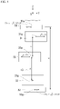
- Fig. 3 is a schematic front view of the shaft.
- Fig. 4 is a schematic side view of the shaft.
- Figs. 3 and 4 schematically illustrate shapes and positions of the shaft 13, the first balancer 51, and the second balancer 52 for ease of understanding.
- a first distance in the Z direction between the center of gravity 31g of the first eccentric part 31 and the center of gravity 32g of the second eccentric part 32 is L.
- a second distance in the Z direction between the center of gravity 32g of the second eccentric part 32 and the center of gravity 33g of the third eccentric part 33 is kL.
- k is a ratio of the second distance to the first distance.
- a distance in the Z direction between a center of gravity 51g of the first balancer 51 and a center of gravity 52g of the second balancer 52 is B.
- an X-direction component Fbx of a centrifugal force acting on the first balancer 51 in which a moment of force acting on the shaft 13 around a Y axis is 0, is obtained.
- the center of gravity 33g of the third eccentric part 33 is used as a reference point.
- a moment of force My acting on the shaft 13 around the Y axis due to the X-direction component of the centrifugal force F acting on the plurality of eccentric parts 30 is expressed by mathematical expression 1.
- the center of gravity 52g of the second balancer 52 is used as a reference point.
- the X-direction component of the centrifugal force acting on the first balancer 51 due to rotation of the shaft 13 is assumed to be Fbx.
- a moment of force Mby acting on the shaft 13 around the Y axis due to the X-direction component Fbx of the centrifugal force acting on the first balancer 51 is expressed by mathematical expression 2.
- Mby B ⁇ Fbx
- Fbx satisfying mathematical expression 3 is expressed by mathematical expression 4.
- Fbx 2 k + 1 LF / 2 B
- a mass, a position, and a shape of the first balancer 51 are set so that the X-direction component Fbx of the centrifugal force acting on the first balancer 51 satisfies mathematical expression 4.
- a mass, a position, and a shape of the second balancer 52 are set so that the X-direction component -Fbx of the centrifugal force acting on the second balancer 52 satisfies mathematical expression 5.
- a Y-direction component Fby of the centrifugal force acting on the first balancer 51, in which a moment of force acting on the shaft 13 around an X axis is 0, is obtained.
- the center of gravity 33g of the third eccentric part 33 is used as a reference point.
- a moment of force Mx acting on the shaft 13 around the X axis due to the Y-direction component of the centrifugal force F acting on the plurality of eccentric parts 30 is expressed by mathematical expression 6.
- the center of gravity 52g of the second balancer 52 is used as a reference point.
- the Y-direction component of the centrifugal force acting on the first balancer 51 due to rotation of the shaft 13 is assumed to be Fby.
- a moment of force Mbx acting on the shaft 13 around the X axis due to the Y-direction component Fby of the centrifugal force acting on the first balancer 51 is expressed by mathematical expression 7.
- Mbx B ⁇ Fby
- a mass, a position, and a shape of the first balancer 51 are set so that the Y-direction component Fby of the centrifugal force acting on the first balancer 51 satisfies mathematical expression 9.
- a Y-direction component of the centrifugal force acting on the second balancer 52 due to rotation of the shaft 13 is -Fby.
- -Fby is expressed by mathematical expression 10.
- ⁇ Fby ⁇ 3 ⁇ LF / 2 B
- a mass, a position, and a shape of the second balancer 52 are set so that the Y-direction component Fby of the centrifugal force acting on the second balancer 52 satisfies mathematical expression 10.
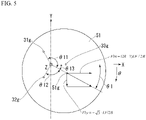
- Fig. 5 is a bottom view of the first balancer.
- the X-direction component Fbx of the centrifugal force acting on the first balancer 51 in which the moment of force acting on the shaft 13 is 0, is expressed by mathematical expression 4
- the Y-direction component Fby is expressed by mathematical expression 9.
- An angle ⁇ 1(rad) of a direction of eccentricity of the center of gravity 51g of the first balancer 51 from the central axis of the shaft 13 with respect to the +X direction in the ⁇ direction is expressed by mathematical expression 11.
- ⁇ 1 arctan A
- A ⁇ 3 / 2 k + 1
- Angles between the direction of eccentricity of the center of gravity 51g of the first balancer 51 with respect to the central axis of the shaft 13 and directions of eccentricity of the centers of gravity of the plurality of eccentric parts 30 with respect to the central axis of the shaft 13 are defined as follows.
- the angle with respect to a direction of eccentricity of the center of gravity 31g of the first eccentric part 31 is ⁇ 11.
- the angle with respect to a direction of eccentricity of the center of gravity 32g of the second eccentric part 32 is ⁇ 12.
- the angle with respect to a direction of eccentricity of the center of gravity 33g of the third eccentric part 33 is ⁇ 13.
- the angle increases in an order of ⁇ 13, ⁇ 12, and ⁇ 11 from the smallest.
- the plurality of eccentric parts 30 and the first balancer 51 are set to satisfy mathematical expression 12. Even when the directions of eccentricity of the plurality of eccentric parts 30 are not at equiangular intervals, the moment of force of the shaft 13 is suppressed when mathematical expression 12 is satisfied. Even when the centrifugal force acting on the first balancer 51 does not satisfy mathematical expression 4 or 9, the moment of force of the shaft 13 is suppressed when mathematical expression 12 is satisfied.
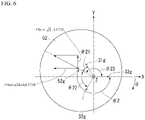
- Fig. 6 is a bottom view of the second balancer.
- the X-direction component -Fbx of the centrifugal force acting on the second balancer 52 in which the moment of force acting on the shaft 13 is 0, is expressed by mathematical expression 5
- the Y-direction component -Fby is expressed by mathematical expression 10.
- An angle ⁇ 2(rad) of a direction of eccentricity of the center of gravity 52g of the second balancer 52 from the central axis of the shaft 13 with respect to the +X direction in the ⁇ direction is expressed by mathematical expression 13.
- ⁇ 2 arctan A + ⁇
- A ⁇ 3 / 2 k + 1
- Angles between the direction of eccentricity of the center of gravity 52g of the second balancer 52 with respect to the central axis of the shaft 13 and the directions of eccentricity of the centers of gravity of the plurality of eccentric parts 30 with respect to the central axis of the shaft 13 are defined as follows.
- the angle with respect to the direction of eccentricity of the center of gravity 31g of the first eccentric part 31 is ⁇ 21.
- the angle with respect to the direction of eccentricity of the center of gravity 32g of the second eccentric part 32 is ⁇ 22.
- the angle with respect to the direction of eccentricity of the center of gravity 33g of the third eccentric part 33 is ⁇ 23.
- the angle increases in an order of ⁇ 21, ⁇ 22, and ⁇ 23 from the smallest.
- the plurality of eccentric parts 30 and the second balancer 52 are set to satisfy mathematical expression 14. Even when the directions of eccentricity of the plurality of eccentric parts 30 are not at equiangular intervals, the moment of force of the shaft 13 is suppressed when mathematical expression 14 is satisfied. Even when the centrifugal force acting on the second balancer 52 does not satisfy mathematical expression 5 or 10, the moment of force of the shaft 13 is suppressed when mathematical expression 14 is satisfied.
- Fig. 7 is a graph illustrating a relationship between a deviation angle of the balancer and a vibration amplitude of the compressor main body.
- the horizontal axis of Fig. 7 represents a deviation angle (°) of the angles ⁇ 1 and ⁇ 2 of the balancers 51 and 52 described above.
- the vertical axis of Fig. 7 is a vibration amplitude ( ⁇ m) of the compressor main body 10.
- the vibration amplitude of the compressor main body 10 becomes larger.
- the vibration amplitude of the compressor main body 10 is 10 ⁇ m or lower.
- the rotary compressor of the embodiment includes the shaft 13, the plurality of compression mechanism units 20, the plurality of eccentric parts 30, the first balancer 51, and the second balancer 52.
- the plurality of eccentric parts 30 include the first eccentric part 31, the second eccentric part 32, and the third eccentric part 33 disposed to be aligned from the +Z direction to the -Z direction in the central axis direction of the shaft 13.
- the second balancer 52 is disposed in the -Z direction of the first balancer 51. Angles between the direction of eccentricity of the first balancer 51 and the directions of eccentricity of the plurality of eccentric parts 30 satisfy mathematical expression 12. Angles between the direction of eccentricity of the second balancer 52 and the directions of eccentricity of the plurality of eccentric parts 30 satisfy mathematical expression 14.
- the moment of force of the shaft 13 caused by the three eccentric parts 31, 32, and 33 is suppressed by the two balancers 51 and 52. Thereby, vibration of the rotary compressor 2 is suppressed. Decrease in reliability and deterioration in performance of the rotary compressor 2 due to bending of the shaft 13 are suppressed. Therefore, the rotary compressor 2 having low vibration, high reliability, and high performance can be provided.
- An angle in a direction of eccentricity of the first balancer 51 with respect to the +X direction is assumed to be ⁇ 1(rad).
- An angle in a direction of eccentricity of the second balancer 52 with respect to the +X direction is assumed to be ⁇ 2(rad).
- ⁇ 1 and ⁇ 2 satisfy mathematical expressions 15 and 16.
- the plurality of eccentric parts 30 are disposed between the first balancer 51 and the second balancer 52 in the Z direction.
- the center of the moment of force acting on the shaft 13 due to the centrifugal force of the plurality of eccentric parts 30 and the center of the moment of force acting on the shaft 13 due to the centrifugal force of the two balancers 51 and 52 approach each other. Therefore, bending of the shaft 13 due to the deviation of the center of the moment of force is suppressed. Therefore, the rotary compressor 2 having low vibration, high reliability, and high performance can be provided.
- the intermediate bearing 45 that supports the shaft 13 is disposed in a region in which a distance in the Z direction is larger.
- the intermediate bearing 45 is disposed near the center of the plurality of compression mechanism units 20, bending of the shaft 13 or the like is suppressed. Thereby, the rotary compressor 2 having low vibration, high reliability, and high performance can be provided.
- the rotary compressor 2 further includes the electric motor unit 15, the first bearing 17, and the second bearing 18.
- the first balancer 51 is disposed in the +Z direction of the electric motor unit 15.
- the second balancer 52 is disposed in the -Z direction of the second bearing 18.
- the refrigeration cycle device 1 of the embodiment includes the rotary compressor 2 described above, the radiator 3 connected to the rotary compressor 2, the expansion device 4 connected to the radiator 3, and the heat absorber 5 connected to the expansion device 4.
- the refrigeration cycle device 1 having low vibration, high reliability, and high performance can be provided.
- Fig. 8 is a cross-sectional view of a rotary compressor of a first modified example of the embodiment.
- the first modified example is different from the embodiment in terms of positions and shapes of the balancers 51 and 52.
- first balancer 51 and the second balancer 52 rotate together with the shaft 13.
- the second balancer 52 is disposed in the -Z direction of the first balancer 51.
- the plurality of eccentric parts 30 are disposed between the first balancer 51 and the second balancer 52 in the Z direction.
- the first balancer 51 is disposed in the +Z direction of the plurality of eccentric parts 30.
- the first balancer 51 is disposed in the -Z direction of the electric motor unit 15.
- the first balancer 51 is fixed to an end surface of the rotor 15b of the electric motor unit 15 in the -Z direction.
- the second balancer 52 is disposed in the -Z direction of the plurality of eccentric parts 30.
- the second balancer 52 is disposed in the -Z direction of the second bearing 18.
- a surface of the second balancer 52 in the +Z direction is disposed along a surface of the second bearing 18 in the -Z direction.
- the rotary compressor 2 of the first modified example satisfies mathematical expressions 12, 14, 15, and 16.
- the plurality of eccentric parts 30 are disposed between the first balancer 51 and the second balancer 52 in the Z direction. Thereby, the rotary compressor 2 having low vibration, high reliability, and high performance can be provided.
- Fig. 9 is a cross-sectional view of a rotary compressor of a second modified example of the embodiment.
- the second modified example is different from the embodiment in terms of positions and shapes of the balancers 51 and 52.
- first balancer 51 and the second balancer 52 rotate together with the shaft 13.
- the second balancer 52 is disposed in the -Z direction of the first balancer 51.
- the first balancer 51 is disposed in the +Z direction of the plurality of eccentric parts 30.
- the first balancer 51 is disposed in the +Z direction of the electric motor unit 15.
- the first balancer 51 is fixed to an end surface of the rotor 15b of the electric motor unit 15 in the +Z direction.
- the second balancer 52 is disposed in the +Z direction of the plurality of eccentric parts 30.
- the second balancer 52 is disposed in the -Z direction of the electric motor unit 15.
- the second balancer 52 is fixed to an end surface of the rotor 15b of the electric motor unit 15 in the -Z direction.
- the rotary compressor 2 of the second modified example satisfies mathematical expressions 12, 14, 15, and 16. Thereby, the rotary compressor 2 having low vibration, high reliability, and high performance can be provided.
- the rotary compressor 2 of the embodiment illustrated in Fig. 1 is a so-called rotary type compressor in which the blade (not illustrated) and the roller 35 are separate bodies.
- the rotary compressor may be a swing type compressor in which the blade and the roller are integrated.
- the balancers 51 and 52 satisfying mathematical expressions 12 and 14 are provided.
- the rotary compressor 2 having low vibration, high reliability, and high performance can be provided.
Landscapes
- Engineering & Computer Science (AREA)
- Mechanical Engineering (AREA)
- General Engineering & Computer Science (AREA)
- Physics & Mathematics (AREA)
- Thermal Sciences (AREA)
- Applications Or Details Of Rotary Compressors (AREA)
Abstract
Description
- Embodiments of the present invention relate to a rotary compressor and a refrigeration cycle device.
- In a refrigeration cycle device, a multi-cylinder rotary compressor having high compression performance is utilized. A multi-cylinder rotary compressor includes a plurality of compression mechanism units, a shaft, and a plurality of eccentric parts. The plurality of eccentric parts are provided on the shaft and are disposed in each of the plurality of compression mechanism units. Directions of eccentricity of the plurality of eccentric parts differ in a circumferential direction of the shaft. When the plurality of eccentric parts rotate together with the shaft, the rotary compressor vibrates. A rotary compressor in which vibration can be suppressed is required.
- [Patent Document1]
PCT International Publication No. WO 2019/186695 - A problem to be solved by the present invention is to provide a rotary compressor and a refrigeration cycle device in which vibration can be suppressed.
- A rotary compressor according to an embodiment includes a shaft, a plurality of compression mechanism units, a plurality of eccentric parts, a first balancer, and a second balancer. The shaft is rotatable around a central axis. The plurality of compression mechanism units include a first compression mechanism unit, a second compression mechanism unit, and a third compression mechanism unit disposed to be aligned from one side to the other side in a central axis direction of the shaft. The plurality of eccentric parts are provided on the shaft and include a first eccentric part, a second eccentric part, and a third eccentric part disposed in corresponding to the first compression mechanism unit, the second compression mechanism unit, and the third compression mechanism unit. The first balancer rotates together with the shaft. The second balancer is disposed on the other side of the first balancer and rotates together with the shaft. Angles between a direction of eccentricity of the first balancer with respect to the central axis of the shaft and directions of eccentricity of the plurality of eccentric parts with respect to the central axis of the shaft are configured to increase in an order of the third eccentric part, the second eccentric part, and the first eccentric part. Angles between a direction of eccentricity of the second balancer with respect to the central axis of the shaft and directions of eccentricity of the plurality of eccentric parts with respect to the central axis of the shaft are configured to increase in an order of the first eccentric part, the second eccentric part, and the third eccentric part.
-
-
Fig. 1 is a schematic configuration view of a refrigeration cycle device including a cross-sectional view of a rotary compressor according to an embodiment. -
Fig. 2 is a bottom view of a plurality of eccentric parts. -
Fig. 3 is a schematic front view of a shaft. -
Fig. 4 is a schematic side view of the shaft. -
Fig. 5 is a bottom view of a first balancer. -
Fig. 6 is a bottom view of a second balancer. -
Fig. 7 is a graph illustrating a relationship between a deviation angle of the balancer and a vibration amplitude of a compressor main body. -
Fig. 8 is a cross-sectional view of a rotary compressor according to a first modified example of the embodiment. -
Fig. 9 is a cross-sectional view of a rotary compressor according to a second modified example of the embodiment. - Hereinafter, a rotary compressor and a refrigeration cycle device of an embodiment will be described with reference to the drawings.
-
Fig. 1 is a schematic configuration view of a refrigeration cycle device including a cross-sectional view of a rotary compressor according to the embodiment. In the present application, a Z direction, an X direction, and a Y direction of an orthogonal coordinate system are defined as follows. The Z direction is a central axis direction of ashaft 13. A +Z direction (one side) is a direction from acompression mechanism unit 20 toward anelectric motor unit 15, and a -Z direction (the other side) is a side opposite to the +Z direction. For example, the Z direction is a vertical direction, and the +Z direction is vertically upward. The X direction and the Y direction are radial directions of theshaft 13. The X direction is a direction of eccentricity of a thirdeccentric part 33 with respect to the central axis of theshaft 13. For example, the X direction and the Y direction are horizontal directions. - A
refrigeration cycle device 1 will be briefly described. - The
refrigeration cycle device 1 includes arotary compressor 2, a radiator (for example, a condenser) 3 connected to therotary compressor 2, an expansion device (for example, an expansion valve) 4 connected to theradiator 3, and a heat absorber (for example, an evaporator) 5 connected to theexpansion device 4. Therefrigeration cycle device 1 contains a refrigerant such as carbon dioxide (CO2). The refrigerant circulates in therefrigeration cycle device 1 while changing its phase. - The
rotary compressor 2 is a so-called rotary type compressor. Therotary compressor 2 compresses a low-pressure gaseous refrigerant (fluid) taken into the inside into a high-temperature and high-pressure gaseous refrigerant. A specific configuration of therotary compressor 2 will be described later. - The
radiator 3 dissipates heat from the high-temperature and high-pressure gaseous refrigerant discharged from therotary compressor 2 to convert the high-temperature and high-pressure gaseous refrigerant into a high-pressure liquid refrigerant. - The
expansion device 4 reduces a pressure of the high-pressure liquid refrigerant sent from theradiator 3 to convert the high-pressure liquid refrigerant into a low-temperature and low-pressure liquid refrigerant. - The heat absorber 5 evaporates the low-temperature and low-pressure liquid refrigerant sent from the
expansion device 4 to convert it into a low-pressure gaseous refrigerant. In the heat absorber 5, evaporation of the low-pressure liquid refrigerant takes evaporation heat from the surroundings, and thus the surroundings are cooled. The low-pressure gaseous refrigerant that has passed through theheat absorber 5 is taken into therotary compressor 2 described above. - As described above, a refrigerant serving as a working fluid circulates while changing its phase between a gaseous refrigerant and a liquid refrigerant in the
refrigeration cycle device 1 of the present embodiment. The refrigerant dissipates heat in the process of changing phase from the gaseous refrigerant to the liquid refrigerant and absorbs heat in the process of changing phase from the liquid refrigerant to the gaseous refrigerant. Heating, cooling, or the like is performed by utilizing such heat dissipation and heat absorption. - The
rotary compressor 2 will be described. - The
rotary compressor 2 includes anaccumulator 6 and a compressormain body 10. Theaccumulator 6 separates the refrigerant sent from the heat absorber 5 into a gaseous refrigerant and a liquid refrigerant. The gaseous refrigerant is taken into the compressormain body 10 through a suction pipe. - The compressor
main body 10 includes acase 11, theshaft 13, theelectric motor unit 15, and a plurality ofcompression mechanism units 20. - The
case 11 is formed in a cylindrical shape with both end portions closed. Thecase 11 houses theshaft 13, theelectric motor unit 15, and the plurality ofcompression mechanism units 20. Thecase 11 includes adischarge unit 19 at an upper end portion. Thedischarge unit 19 supplies the gaseous refrigerant inside thecase 11 to theradiator 3. - The
shaft 13 is disposed along the central axis of the compressormain body 10. Theshaft 13 includes a plurality ofeccentric parts 30. Details of the plurality ofeccentric parts 30 will be described later. - The
electric motor unit 15 is disposed in the +Z direction of theshaft 13. Theelectric motor unit 15 includes astator 15a and arotor 15b. Thestator 15a is fixed to an inner circumferential surface of thecase 11. Therotor 15b is fixed to an outer circumferential surface of theshaft 13. Theelectric motor unit 15 rotationally drives theshaft 13. - The plurality of
compression mechanism units 20 compress the gaseous refrigerant by rotation of theshaft 13. The plurality ofcompression mechanism units 20 are disposed in the -Z direction of theshaft 13. The plurality ofcompression mechanism units 20 include a set of threecompression mechanism units 20 including a firstcompression mechanism unit 21, a secondcompression mechanism unit 22, and a thirdcompression mechanism unit 23. The firstcompression mechanism unit 21, the secondcompression mechanism unit 22, and the thirdcompression mechanism unit 23 are disposed to be aligned in that order from the +Z direction to the -Z direction. Hereinafter, a configuration of the firstcompression mechanism unit 21 will be described as a representative. Configurations of the secondcompression mechanism unit 22 and the thirdcompression mechanism unit 23 are the same as that of the firstcompression mechanism unit 21 except for a direction of eccentricity of theeccentric parts 30. - The first
compression mechanism unit 21 includes a firsteccentric part 31, aroller 35, and acylinder 37. - The first
eccentric part 31 has a columnar shape and is integrally formed with theshaft 13. When viewed from the +Z direction, a center of the firsteccentric part 31 is eccentric from the central axis of theshaft 13. - The
roller 35 is formed in a cylindrical shape and is disposed along an outer circumference of the firsteccentric part 31. - The
cylinder 37 is fixed to a frame 12. An outer circumferential surface of the frame 12 is fixed to an inner circumferential surface of thecase 11. Thecylinder 37 includes a first cylinder chamber 21c, a vane (not illustrated), and asuction hole 39. The first cylinder chamber 21c is formed to penetrate a center of thecylinder 37 in the Z direction. The first cylinder chamber 21c houses the firsteccentric part 31 and theroller 35 therein. The vane is housed in a vane groove formed in thecylinder 37 and can advance into and retreat from the inside of the first cylinder chamber 21c. The vane is urged so that a distal end portion thereof is brought into contact with an outer circumferential surface of theroller 35. The vane, together with the firsteccentric part 31 and theroller 35, partitions the inside of the first cylinder chamber 21c into a suction chamber and a compression chamber. Thesuction hole 39 takes the gaseous refrigerant into the suction chamber of the first cylinder chamber 21c from theaccumulator 6. - The
rotary compressor 2 includes afirst bearing 17, asecond bearing 18, afirst partition part 41, asecond partition part 42, afirst muffler 27, and a second muffler 28. - The
first bearing 17 is disposed in the +Z direction of the plurality ofcompression mechanism units 20 and supports theshaft 13. Thesecond bearing 18 is disposed in the -Z direction of the plurality ofcompression mechanism units 20 and supports theshaft 13. - The
first partition part 41 is disposed between the firstcompression mechanism unit 21 and the secondcompression mechanism unit 22. Thesecond partition part 42 is disposed between the secondcompression mechanism unit 22 and the thirdcompression mechanism unit 23. - The
first muffler 27 forms afirst muffler chamber 27c between itself and thefirst bearing 17. The gaseous refrigerant compressed by the firstcompression mechanism unit 21 is discharged to thefirst muffler chamber 27c. The gaseous refrigerant discharged to thefirst muffler chamber 27c is discharged to the inside of thecase 11. - The second muffler 28 forms a
second muffler chamber 28c between itself and thesecond bearing 18. The gaseous refrigerant compressed by the thirdcompression mechanism unit 23 is discharged to thesecond muffler chamber 28c. Thesecond muffler chamber 28c communicates with thefirst muffler chamber 27c via a passage between muffler chambers (not illustrated). - The gaseous refrigerant compressed by the second
compression mechanism unit 22 is discharged to a partition part passage 46 formed in thesecond partition part 42. The partition part passage 46 communicates with the passage between the muffler chambers described above. - A region between a center of
gravity 31g of the firsteccentric part 31 and a center ofgravity 32g of the secondeccentric part 32 is a first region R1. A region between the center ofgravity 32g of the secondeccentric part 32 and a center ofgravity 33g of the thirdeccentric part 33 is a second region R2. A distance of the second region R2 in the Z direction is larger than a distance of the first region R1 in the Z direction. Anintermediate bearing 45 that supports theshaft 13 is disposed in the second region R2. Thesecond partition part 42 described above is disposed in the second region R2. Thesecond partition part 42 includes apartition member 43 and theintermediate bearing 45. Thepartition member 43 is disposed in the -Z direction, and theintermediate bearing 45 is disposed in the +Z direction. Anenlarged diameter part 14 of theshaft 13 is formed at a position in the Z direction at which theintermediate bearing 45 is disposed. A through hole 47 formed at a center of theintermediate bearing 45 supports theenlarged diameter part 14 of theshaft 13. - The plurality of
compression mechanism units 20 are disposed between thefirst bearing 17 and thesecond bearing 18. Bending of theshaft 13 increases between thefirst bearing 17 and thesecond bearing 18. Theintermediate bearing 45 is disposed near a center of the plurality ofcompression mechanism units 20 in the Z direction. Theintermediate bearing 45 suppresses the bending of theshaft 13. Thereby, therotary compressor 2 having low vibration, high reliability, and high performance can be provided. - The plurality of
eccentric parts 30 will be described. - The plurality of
eccentric parts 30 include the firsteccentric part 31, the secondeccentric part 32, and the thirdeccentric part 33. The firsteccentric part 31, the secondeccentric part 32, and the thirdeccentric part 33 are disposed in the firstcompression mechanism unit 21, the secondcompression mechanism unit 22, and the thirdcompression mechanism unit 23, respectively. -
Fig. 2 is a bottom view of the plurality of eccentric parts. The plurality ofeccentric parts 30 are eccentric with respect to the central axis of theshaft 13. Directions of eccentricity of the plurality ofeccentric parts 30 are different from each other in a circumferential direction of theshaft 13. It is desirable that the directions of eccentricity of the plurality ofeccentric parts 30 be at equiangular intervals in the circumferential direction of theshaft 13. The directions of eccentricity of the firsteccentric part 31, the secondeccentric part 32, and the thirdeccentric part 33 are at equiangular intervals of 120° in the circumferential direction of theshaft 13. - In the present application, a θ direction is a rotation direction of a right-hand screw traveling in the +Z direction.
- As described above, the direction of eccentricity of the third
eccentric part 33 is the X direction. A direction of eccentricity of the secondeccentric part 32 is in a direction of 120° in the θ direction from the X direction which is the direction of eccentricity of the thirdeccentric part 33. A direction of eccentricity of the firsteccentric part 31 is in a direction of 120° in the θ direction from the direction of eccentricity of the secondeccentric part 32. - When the
shaft 13 rotates, a centrifugal force F acts on the centers of gravity of the plurality ofeccentric parts 30. Magnitudes of the centrifugal forces F acting on the plurality ofeccentric parts 30 are the same. An X-direction component of the centrifugal force acting on the center ofgravity 33g of the thirdeccentric part 33 is F, and a Y-direction component thereof is 0. An X-direction component of the centrifugal force acting on the center ofgravity 32g of the secondeccentric part 32 is -F/2, and a Y-direction component thereof is -√3·F/2. An X-direction component of the centrifugal force acting on the center ofgravity 31g of the firsteccentric part 31 is -F/2, and a Y-direction component thereof is √3·F/2. A moment (swinging moment, rotational moment) of force acts on theshaft 13 due to the centrifugal force F acting on the plurality ofeccentric parts 30. - The
rotary compressor 2 illustrated inFig. 1 includes a balancer (counter balancer) that suppresses the moment of force acting on theshaft 13. Therotary compressor 2 includes afirst balancer 51 and asecond balancer 52. Thefirst balancer 51 and thesecond balancer 52 rotate together with theshaft 13. Thesecond balancer 52 is disposed in the -Z direction of thefirst balancer 51. The plurality ofeccentric parts 30 are disposed between thefirst balancer 51 and thesecond balancer 52 in the Z direction. - The
first balancer 51 is disposed in the +Z direction of the plurality ofeccentric parts 30. Thefirst balancer 51 is disposed in the +Z direction of theelectric motor unit 15. Thefirst balancer 51 is fixed to an end surface of therotor 15b of theelectric motor unit 15 in the +Z direction. Thefirst balancer 51 rotates together with therotor 15b and theshaft 13. - The
second balancer 52 is disposed in the -Z direction of the plurality ofeccentric parts 30. Thesecond balancer 52 is disposed inside the second muffler 28 in the -Z direction of thesecond bearing 18. Thesecond balancer 52 is formed separately from theshaft 13. Thesecond balancer 52 is fixed to theshaft 13 by a fixing means such as a screw. Thesecond balancer 52 rotates together with theshaft 13. -
Fig. 3 is a schematic front view of the shaft.Fig. 4 is a schematic side view of the shaft.Figs. 3 and4 schematically illustrate shapes and positions of theshaft 13, thefirst balancer 51, and thesecond balancer 52 for ease of understanding. A first distance in the Z direction between the center ofgravity 31g of the firsteccentric part 31 and the center ofgravity 32g of the secondeccentric part 32 is L. A second distance in the Z direction between the center ofgravity 32g of the secondeccentric part 32 and the center ofgravity 33g of the thirdeccentric part 33 is kL. k is a ratio of the second distance to the first distance. A distance in the Z direction between a center ofgravity 51g of thefirst balancer 51 and a center ofgravity 52g of thesecond balancer 52 is B. - Using
Fig. 3 , an X-direction component Fbx of a centrifugal force acting on thefirst balancer 51, in which a moment of force acting on theshaft 13 around a Y axis is 0, is obtained. For example, the center ofgravity 33g of the thirdeccentric part 33 is used as a reference point. A moment of force My acting on theshaft 13 around the Y axis due to the X-direction component of the centrifugal force F acting on the plurality ofeccentric parts 30 is expressed bymathematical expression 1.
- For example, the center of
gravity 52g of thesecond balancer 52 is used as a reference point. The X-direction component of the centrifugal force acting on thefirst balancer 51 due to rotation of theshaft 13 is assumed to be Fbx. A moment of force Mby acting on theshaft 13 around the Y axis due to the X-direction component Fbx of the centrifugal force acting on thefirst balancer 51 is expressed bymathematical expression 2.
- When the following
mathematical expression 3 is established, the moment of force acting on theshaft 13 around the Y axis is 0.
- Fbx satisfying
mathematical expression 3 is expressed bymathematical expression 4.
- A mass, a position, and a shape of the
first balancer 51 are set so that the X-direction component Fbx of the centrifugal force acting on thefirst balancer 51 satisfiesmathematical expression 4. - An X-direction component of the centrifugal force acting on the
second balancer 52 due to rotation of theshaft 13 is -Fbx. -Fbx is expressed bymathematical expression 5.
- A mass, a position, and a shape of the
second balancer 52 are set so that the X-direction component -Fbx of the centrifugal force acting on thesecond balancer 52 satisfiesmathematical expression 5. - Using
Fig. 4 , a Y-direction component Fby of the centrifugal force acting on thefirst balancer 51, in which a moment of force acting on theshaft 13 around an X axis is 0, is obtained. For example, the center ofgravity 33g of the thirdeccentric part 33 is used as a reference point. A moment of force Mx acting on theshaft 13 around the X axis due to the Y-direction component of the centrifugal force F acting on the plurality ofeccentric parts 30 is expressed bymathematical expression 6.
- For example, the center of
gravity 52g of thesecond balancer 52 is used as a reference point. The Y-direction component of the centrifugal force acting on thefirst balancer 51 due to rotation of theshaft 13 is assumed to be Fby. A moment of force Mbx acting on theshaft 13 around the X axis due to the Y-direction component Fby of the centrifugal force acting on thefirst balancer 51 is expressed by mathematical expression 7.
- When the following mathematical expression 8 is established, the moment of force acting on the
shaft 13 around the X axis is 0.
- Fby satisfying mathematical expression 8 is expressed by mathematical expression 9.

- A mass, a position, and a shape of the
first balancer 51 are set so that the Y-direction component Fby of the centrifugal force acting on thefirst balancer 51 satisfies mathematical expression 9. - A Y-direction component of the centrifugal force acting on the
second balancer 52 due to rotation of theshaft 13 is -Fby. -Fby is expressed bymathematical expression 10.
- A mass, a position, and a shape of the
second balancer 52 are set so that the Y-direction component Fby of the centrifugal force acting on thesecond balancer 52 satisfiesmathematical expression 10. -
Fig. 5 is a bottom view of the first balancer. As described above, the X-direction component Fbx of the centrifugal force acting on thefirst balancer 51, in which the moment of force acting on theshaft 13 is 0, is expressed bymathematical expression 4, and the Y-direction component Fby is expressed by mathematical expression 9. An angle θ1(rad) of a direction of eccentricity of the center ofgravity 51g of thefirst balancer 51 from the central axis of theshaft 13 with respect to the +X direction in the θ direction is expressed bymathematical expression 11.
- Angles between the direction of eccentricity of the center of
gravity 51g of thefirst balancer 51 with respect to the central axis of theshaft 13 and directions of eccentricity of the centers of gravity of the plurality ofeccentric parts 30 with respect to the central axis of theshaft 13 are defined as follows. The angle with respect to a direction of eccentricity of the center ofgravity 31g of the firsteccentric part 31 is θ11. The angle with respect to a direction of eccentricity of the center ofgravity 32g of the secondeccentric part 32 is θ12. The angle with respect to a direction of eccentricity of the center ofgravity 33g of the thirdeccentric part 33 is θ13. The angles between the direction of eccentricity of the center ofgravity 51g of thefirst balancer 51 with respect to the central axis of theshaft 13 and the directions of eccentricity of the centers of gravity of the plurality ofeccentric parts 30 with respect to the central axis of theshaft 13 satisfy mathematical expression 12.
- That is, the angle increases in an order of θ13, θ12, and θ11 from the smallest.
- The plurality of
eccentric parts 30 and thefirst balancer 51 are set to satisfy mathematical expression 12. Even when the directions of eccentricity of the plurality ofeccentric parts 30 are not at equiangular intervals, the moment of force of theshaft 13 is suppressed when mathematical expression 12 is satisfied. Even when the centrifugal force acting on thefirst balancer 51 does not satisfymathematical expression 4 or 9, the moment of force of theshaft 13 is suppressed when mathematical expression 12 is satisfied. -
Fig. 6 is a bottom view of the second balancer. As described above, the X-direction component -Fbx of the centrifugal force acting on thesecond balancer 52, in which the moment of force acting on theshaft 13 is 0, is expressed bymathematical expression 5, and the Y-direction component -Fby is expressed bymathematical expression 10. An angle θ2(rad) of a direction of eccentricity of the center ofgravity 52g of thesecond balancer 52 from the central axis of theshaft 13 with respect to the +X direction in the θ direction is expressed bymathematical expression 13.
- Angles between the direction of eccentricity of the center of
gravity 52g of thesecond balancer 52 with respect to the central axis of theshaft 13 and the directions of eccentricity of the centers of gravity of the plurality ofeccentric parts 30 with respect to the central axis of theshaft 13 are defined as follows. The angle with respect to the direction of eccentricity of the center ofgravity 31g of the firsteccentric part 31 is θ21. The angle with respect to the direction of eccentricity of the center ofgravity 32g of the secondeccentric part 32 is θ22. The angle with respect to the direction of eccentricity of the center ofgravity 33g of the thirdeccentric part 33 is θ23. The angles between the direction of eccentricity of the center ofgravity 52g of thesecond balancer 52 with respect to the central axis of theshaft 13 and the directions of eccentricity of the centers of gravity of the plurality ofeccentric parts 30 with respect to the central axis of theshaft 13 satisfymathematical expression 14.
- That is, the angle increases in an order of θ21, θ22, and θ23 from the smallest.
- The plurality of
eccentric parts 30 and thesecond balancer 52 are set to satisfymathematical expression 14. Even when the directions of eccentricity of the plurality ofeccentric parts 30 are not at equiangular intervals, the moment of force of theshaft 13 is suppressed whenmathematical expression 14 is satisfied. Even when the centrifugal force acting on thesecond balancer 52 does not satisfymathematical expression shaft 13 is suppressed whenmathematical expression 14 is satisfied. -
Fig. 7 is a graph illustrating a relationship between a deviation angle of the balancer and a vibration amplitude of the compressor main body. The horizontal axis ofFig. 7 represents a deviation angle (°) of the angles θ1 and θ2 of thebalancers Fig. 7 is a vibration amplitude (µm) of the compressormain body 10. As the deviation angles of the angles θ1 and θ2 of thebalancers main body 10 becomes larger. When the deviation angles of the angles θ1 and θ2 are in a range of ±5° (± π/36 rad), the vibration amplitude of the compressormain body 10 is 10 µm or lower. It is desirable that the angles θ1 and θ2 satisfymathematical expressions 15 and 16, respectively, with A = √3/(2k+1).

- As described in detail above, the rotary compressor of the embodiment includes the
shaft 13, the plurality ofcompression mechanism units 20, the plurality ofeccentric parts 30, thefirst balancer 51, and thesecond balancer 52. The plurality ofeccentric parts 30 include the firsteccentric part 31, the secondeccentric part 32, and the thirdeccentric part 33 disposed to be aligned from the +Z direction to the -Z direction in the central axis direction of theshaft 13. Thesecond balancer 52 is disposed in the -Z direction of thefirst balancer 51. Angles between the direction of eccentricity of thefirst balancer 51 and the directions of eccentricity of the plurality ofeccentric parts 30 satisfy mathematical expression 12. Angles between the direction of eccentricity of thesecond balancer 52 and the directions of eccentricity of the plurality ofeccentric parts 30 satisfymathematical expression 14. - In the three-
cylinder rotary compressor 2, the moment of force of theshaft 13 caused by the threeeccentric parts balancers rotary compressor 2 is suppressed. Decrease in reliability and deterioration in performance of therotary compressor 2 due to bending of theshaft 13 are suppressed. Therefore, therotary compressor 2 having low vibration, high reliability, and high performance can be provided. - An angle in a direction of eccentricity of the
first balancer 51 with respect to the +X direction is assumed to be θ1(rad). An angle in a direction of eccentricity of thesecond balancer 52 with respect to the +X direction is assumed to be θ2(rad). θ1 and θ2 satisfymathematical expressions 15 and 16. - When θ1 satisfies
mathematical expression 11 and θ2 satisfiesmathematical expression 13, the moment of force of theshaft 13 is theoretically 0. When the deviation angle of θ1 frommathematical expression 11 and the deviation angle of θ2 frommathematical expression 13 are ±5°, the vibration amplitude of the compressormain body 10 is suppressed to 10 µm or lower. Therefore, whenmathematical expressions 15 and 16 are satisfied, therotary compressor 2 with low vibration can be provided. - The plurality of
eccentric parts 30 are disposed between thefirst balancer 51 and thesecond balancer 52 in the Z direction. - The center of the moment of force acting on the
shaft 13 due to the centrifugal force of the plurality ofeccentric parts 30 and the center of the moment of force acting on theshaft 13 due to the centrifugal force of the twobalancers shaft 13 due to the deviation of the center of the moment of force is suppressed. Therefore, therotary compressor 2 having low vibration, high reliability, and high performance can be provided. - Of the first region R1 between the center of
gravity 31g of the firsteccentric part 31 and the center ofgravity 32g of the secondeccentric part 32, and the second region R2 between the center ofgravity 32g of the secondeccentric part 32 and the center ofgravity 33g of the thirdeccentric part 33, theintermediate bearing 45 that supports theshaft 13 is disposed in a region in which a distance in the Z direction is larger. - Since the
intermediate bearing 45 is disposed near the center of the plurality ofcompression mechanism units 20, bending of theshaft 13 or the like is suppressed. Thereby, therotary compressor 2 having low vibration, high reliability, and high performance can be provided. - The
rotary compressor 2 further includes theelectric motor unit 15, thefirst bearing 17, and thesecond bearing 18. Thefirst balancer 51 is disposed in the +Z direction of theelectric motor unit 15. Thesecond balancer 52 is disposed in the -Z direction of thesecond bearing 18. - Since a distance between the
balancers balancers rotary compressor 2 can be achieved. - The
refrigeration cycle device 1 of the embodiment includes therotary compressor 2 described above, theradiator 3 connected to therotary compressor 2, theexpansion device 4 connected to theradiator 3, and theheat absorber 5 connected to theexpansion device 4. - Thereby, the
refrigeration cycle device 1 having low vibration, high reliability, and high performance can be provided. -
Fig. 8 is a cross-sectional view of a rotary compressor of a first modified example of the embodiment. The first modified example is different from the embodiment in terms of positions and shapes of thebalancers - Similarly to the embodiment, the
first balancer 51 and thesecond balancer 52 rotate together with theshaft 13. Thesecond balancer 52 is disposed in the -Z direction of thefirst balancer 51. The plurality ofeccentric parts 30 are disposed between thefirst balancer 51 and thesecond balancer 52 in the Z direction. - The
first balancer 51 is disposed in the +Z direction of the plurality ofeccentric parts 30. Thefirst balancer 51 is disposed in the -Z direction of theelectric motor unit 15. Thefirst balancer 51 is fixed to an end surface of therotor 15b of theelectric motor unit 15 in the -Z direction. - The
second balancer 52 is disposed in the -Z direction of the plurality ofeccentric parts 30. Thesecond balancer 52 is disposed in the -Z direction of thesecond bearing 18. A surface of thesecond balancer 52 in the +Z direction is disposed along a surface of thesecond bearing 18 in the -Z direction. - The
rotary compressor 2 of the first modified example satisfiesmathematical expressions eccentric parts 30 are disposed between thefirst balancer 51 and thesecond balancer 52 in the Z direction. Thereby, therotary compressor 2 having low vibration, high reliability, and high performance can be provided. -
Fig. 9 is a cross-sectional view of a rotary compressor of a second modified example of the embodiment. The second modified example is different from the embodiment in terms of positions and shapes of thebalancers - Similarly to the embodiment, the
first balancer 51 and thesecond balancer 52 rotate together with theshaft 13. Thesecond balancer 52 is disposed in the -Z direction of thefirst balancer 51. - The
first balancer 51 is disposed in the +Z direction of the plurality ofeccentric parts 30. Thefirst balancer 51 is disposed in the +Z direction of theelectric motor unit 15. Thefirst balancer 51 is fixed to an end surface of therotor 15b of theelectric motor unit 15 in the +Z direction. - The
second balancer 52 is disposed in the +Z direction of the plurality ofeccentric parts 30. Thesecond balancer 52 is disposed in the -Z direction of theelectric motor unit 15. Thesecond balancer 52 is fixed to an end surface of therotor 15b of theelectric motor unit 15 in the -Z direction. - The
rotary compressor 2 of the second modified example satisfiesmathematical expressions rotary compressor 2 having low vibration, high reliability, and high performance can be provided. - The
rotary compressor 2 of the embodiment illustrated inFig. 1 is a so-called rotary type compressor in which the blade (not illustrated) and theroller 35 are separate bodies. On the other hand, the rotary compressor may be a swing type compressor in which the blade and the roller are integrated. - According to at least one embodiment described above, the
balancers mathematical expressions 12 and 14 are provided. Thereby, therotary compressor 2 having low vibration, high reliability, and high performance can be provided. - While certain embodiments have been described, these embodiments have been presented by way of example only, and are not intended to limit the scope of the inventions. Indeed, the novel embodiments described herein may be embodied in a variety of other forms; furthermore, various omissions, substitutions and changes in the form of the embodiments described herein may be made without departing from the spirit of the inventions. The accompanying claims and their equivalents are intended to cover such forms or modifications as would fall within the scope and spirit of the inventions.
-
- R1 First region
- R2 Second region
- 1 Refrigeration cycle device
- 2 Rotary compressor
- 13 Shaft
- 15 Electric motor unit
- 17 First bearing
- 18 Second bearing
- 20 Plurality of compression mechanism unit
- 21 First compression mechanism unit
- 22 Second compression mechanism unit
- 23 Third compression mechanism unit
- 30 Plurality of eccentric parts
- 31 First eccentric part
- 31g Center of gravity
- 32 Second eccentric part
- 32g Center of gravity
- 33 Third eccentric part
- 33g Center of gravity
- 45 Intermediate bearing
- 51 First balancer
- 52 Second balancer
Claims (6)
- A rotary compressor comprising:a shaft rotatable around a central axis;a plurality of compression mechanism units including a first compression mechanism unit, a second compression mechanism unit, and a third compression mechanism unit disposed to be aligned from one side to the other side in a central axis direction of the shaft;a plurality of eccentric parts provided on the shaft and including a first eccentric part, a second eccentric part, and a third eccentric part disposed in corresponding to the first compression mechanism unit, the second compression mechanism unit, and the third compression mechanism unit;a first balancer rotating together with the shaft; anda second balancer disposed on the other side of the first balancer and rotating together with the shaft, whereinangles between a direction of eccentricity of the first balancer with respect to the central axis of the shaft and directions of eccentricity of the plurality of eccentric parts with respect to the central axis of the shaft are configured to increase in an order of the third eccentric part, the second eccentric part, and the first eccentric part, andangles between a direction of eccentricity of the second balancer with respect to the central axis of the shaft and directions of eccentricity of the plurality of eccentric parts with respect to the central axis of the shaft are configured to increase in an order of the first eccentric part, the second eccentric part, and the third eccentric part.
- The rotary compressor according to claim 1, wherein, when:a ratio of a distance in the central axis direction between a center of gravity of the second eccentric part and a center of gravity of the third eccentric part to a distance in the central axis direction between a center of gravity of the first eccentric part and the center of gravity of the second eccentric part is k;an angle between a direction of eccentricity of the third eccentric part with respect to the central axis of the shaft and the direction of eccentricity of the first balancer with respect to the central axis of the shaft is θ1(rad); andan angle between the direction of eccentricity of the third eccentric part with respect to the central axis of the shaft and the direction of eccentricity of the second balancer with respect to the central axis of the shaft is θ2(rad),


- The rotary compressor according to claim 1 or 2, wherein the plurality of eccentric parts are disposed between the first balancer and the second balancer in the central axis direction.
- The rotary compressor according to any one of claims 1 to 3, wherein an intermediate bearing supporting the shaft is disposed in a region in which a distance in the central axis direction is larger between a first region between the center of gravity of the first eccentric part and the center of gravity of the second eccentric part and a second region between the center of gravity of the second eccentric part and the center of gravity of the third eccentric part.
- The rotary compressor according to any one of claims 1 to 4, further comprising:an electric motor unit disposed on the one side of the plurality of compression mechanism units and rotationally driving the shaft;a first bearing disposed on the one side of the plurality of compression mechanism units and supporting the shaft; anda second bearing disposed on the other side of the plurality of compression mechanism units and supporting the shaft, whereinthe first balancer is disposed on the one side of the electric motor unit, andthe second balancer is disposed on the other side of the second bearing.
- A refrigeration cycle device comprising:the rotary compressor according to any one of claims 1 to 5;a radiator connected to the rotary compressor;an expansion device connected to the radiator; anda heat absorber connected to the expansion device.
Applications Claiming Priority (1)
| Application Number | Priority Date | Filing Date | Title |
|---|---|---|---|
| PCT/JP2020/007348 WO2021171340A1 (en) | 2020-02-25 | 2020-02-25 | Rotary compressor and refrigeration cycle device |
Publications (3)
| Publication Number | Publication Date |
|---|---|
| EP4112939A1 true EP4112939A1 (en) | 2023-01-04 |
| EP4112939A4 EP4112939A4 (en) | 2023-11-08 |
| EP4112939B1 EP4112939B1 (en) | 2025-07-23 |
Family
ID=77491278
Family Applications (1)
| Application Number | Title | Priority Date | Filing Date |
|---|---|---|---|
| EP20921005.3A Active EP4112939B1 (en) | 2020-02-25 | 2020-02-25 | Rotary compressor and refrigeration cycle device |
Country Status (5)
| Country | Link |
|---|---|
| US (1) | US12140347B2 (en) |
| EP (1) | EP4112939B1 (en) |
| JP (1) | JP7389220B2 (en) |
| CN (1) | CN114630963B (en) |
| WO (1) | WO2021171340A1 (en) |
Families Citing this family (1)
| Publication number | Priority date | Publication date | Assignee | Title |
|---|---|---|---|---|
| WO2023190346A1 (en) * | 2022-03-31 | 2023-10-05 | ダイキン工業株式会社 | Compressor and refrigeration device |
Family Cites Families (14)
| Publication number | Priority date | Publication date | Assignee | Title |
|---|---|---|---|---|
| JPH05187374A (en) * | 1992-01-13 | 1993-07-27 | Sanyo Electric Co Ltd | Closed compressor |
| JPH0610863A (en) * | 1992-06-26 | 1994-01-21 | Daikin Ind Ltd | 3-cylinder type rotary compressor |
| KR19980073118A (en) * | 1997-03-12 | 1998-11-05 | 구자홍 | Rotary Compressor Balancer |
| JP2004270654A (en) * | 2003-03-12 | 2004-09-30 | Denso Corp | Rotary compressor |
| JP2008063973A (en) * | 2006-09-05 | 2008-03-21 | Toshiba Kyaria Kk | 2-cylinder rotary compressor, refrigeration cycle equipment |
| JP5304868B2 (en) * | 2011-09-30 | 2013-10-02 | ダイキン工業株式会社 | Scroll compressor |
| CN103452844B (en) * | 2012-06-04 | 2016-01-20 | 广东美芝制冷设备有限公司 | Rotary compressor |
| JP2014129755A (en) * | 2012-12-28 | 2014-07-10 | Daikin Ind Ltd | Rotary compressor |
| JP6077352B2 (en) * | 2013-03-26 | 2017-02-08 | 東芝キヤリア株式会社 | Multi-cylinder rotary compressor and refrigeration cycle apparatus |
| JP6419186B2 (en) * | 2014-08-01 | 2018-11-07 | 東芝キヤリア株式会社 | Rotary compressor and refrigeration cycle apparatus |
| CN204532830U (en) * | 2015-04-01 | 2015-08-05 | 广东美芝制冷设备有限公司 | Rotary compressor |
| CN104728118B (en) * | 2015-04-01 | 2017-06-16 | 广东美芝制冷设备有限公司 | Rotary compressor |
| JP6805388B2 (en) * | 2018-03-08 | 2020-12-23 | 株式会社東芝 | Rotary compressor and refrigeration cycle equipment |
| KR102340873B1 (en) | 2018-03-27 | 2021-12-17 | 도시바 캐리어 가부시키가이샤 | ROTARY COMPRESSOR AND REFRIGERATION CYCLE DEVICE |
-
2020
- 2020-02-25 EP EP20921005.3A patent/EP4112939B1/en active Active
- 2020-02-25 JP JP2022502348A patent/JP7389220B2/en active Active
- 2020-02-25 CN CN202080076436.2A patent/CN114630963B/en active Active
- 2020-02-25 WO PCT/JP2020/007348 patent/WO2021171340A1/en not_active Ceased
-
2022
- 2022-08-11 US US17/819,020 patent/US12140347B2/en active Active
Also Published As
| Publication number | Publication date |
|---|---|
| CN114630963A (en) | 2022-06-14 |
| EP4112939A4 (en) | 2023-11-08 |
| WO2021171340A1 (en) | 2021-09-02 |
| EP4112939B1 (en) | 2025-07-23 |
| JPWO2021171340A1 (en) | 2021-09-02 |
| US12140347B2 (en) | 2024-11-12 |
| CN114630963B (en) | 2024-07-02 |
| US20220390153A1 (en) | 2022-12-08 |
| JP7389220B2 (en) | 2023-11-29 |
Similar Documents
| Publication | Publication Date | Title |
|---|---|---|
| US11339999B2 (en) | Compressor and accumulator with multiple suction tubes for a refrigeration cycle device | |
| CN104838145B (en) | Multi-cylinder rotary compressor and refrigeration cycle device | |
| EP3447296A1 (en) | Compressor | |
| JP2013096280A (en) | Rotary compressor | |
| JP2016533447A (en) | Spin pump with planetary rotation mechanism | |
| US12140347B2 (en) | Rotary compressor and refrigeration cycle device | |
| ES2774806T3 (en) | Compressor | |
| KR20200112247A (en) | Scroll compressor | |
| US10962010B2 (en) | Compressor | |
| US20210341188A1 (en) | Compressor and refrigeration cycle device | |
| JP2014185565A (en) | Multi-cylinder rotary compressor and refrigeration cycle device | |
| JP2004270654A (en) | Rotary compressor | |
| EP3249228A1 (en) | Compressor | |
| US11466687B2 (en) | Rotary compressor and refrigeration cycle apparatus | |
| JP2016160793A (en) | Rotary compressor and refrigeration cycle apparatus | |
| JP6019669B2 (en) | Rotary compressor | |
| JP2009097394A (en) | Hermetic compressor | |
| CN222717353U (en) | Rotor balance block and rotor structure | |
| US20210340984A1 (en) | Compressor | |
| CN104929940A (en) | Piston of rotary compressor and rotary compressor with same and multistage compressor with same | |
| CN105003436A (en) | Compressing mechanism for rotary compressor and rotary compressor with compressing mechanism | |
| EP3217014B1 (en) | Compressor | |
| JP4100238B2 (en) | Fluid machinery | |
| EP4464897A1 (en) | Rotary compressor and refrigeration device having same | |
| WO2019102748A1 (en) | Rotary compressor |
Legal Events
| Date | Code | Title | Description |
|---|---|---|---|
| STAA | Information on the status of an ep patent application or granted ep patent |
Free format text: STATUS: THE INTERNATIONAL PUBLICATION HAS BEEN MADE |
|
| PUAI | Public reference made under article 153(3) epc to a published international application that has entered the european phase |
Free format text: ORIGINAL CODE: 0009012 |
|
| STAA | Information on the status of an ep patent application or granted ep patent |
Free format text: STATUS: REQUEST FOR EXAMINATION WAS MADE |
|
| 17P | Request for examination filed |
Effective date: 20220811 |
|
| AK | Designated contracting states |
Kind code of ref document: A1 Designated state(s): AL AT BE BG CH CY CZ DE DK EE ES FI FR GB GR HR HU IE IS IT LI LT LU LV MC MK MT NL NO PL PT RO RS SE SI SK SM TR |
|
| DAV | Request for validation of the european patent (deleted) | ||
| DAX | Request for extension of the european patent (deleted) | ||
| A4 | Supplementary search report drawn up and despatched |
Effective date: 20231011 |
|
| RIC1 | Information provided on ipc code assigned before grant |
Ipc: F04C 29/00 20060101ALI20231005BHEP Ipc: F04C 23/00 20060101ALI20231005BHEP Ipc: F04C 18/356 20060101AFI20231005BHEP |
|
| GRAP | Despatch of communication of intention to grant a patent |
Free format text: ORIGINAL CODE: EPIDOSNIGR1 |
|
| STAA | Information on the status of an ep patent application or granted ep patent |
Free format text: STATUS: GRANT OF PATENT IS INTENDED |
|
| RIC1 | Information provided on ipc code assigned before grant |
Ipc: F04C 29/00 20060101ALI20250203BHEP Ipc: F04C 23/00 20060101ALI20250203BHEP Ipc: F04C 18/356 20060101AFI20250203BHEP |
|
| INTG | Intention to grant announced |
Effective date: 20250218 |
|
| GRAS | Grant fee paid |
Free format text: ORIGINAL CODE: EPIDOSNIGR3 |
|
| GRAA | (expected) grant |
Free format text: ORIGINAL CODE: 0009210 |
|
| STAA | Information on the status of an ep patent application or granted ep patent |
Free format text: STATUS: THE PATENT HAS BEEN GRANTED |
|
| RAP3 | Party data changed (applicant data changed or rights of an application transferred) |
Owner name: CARRIER JAPAN CORPORATION |
|
| AK | Designated contracting states |
Kind code of ref document: B1 Designated state(s): AL AT BE BG CH CY CZ DE DK EE ES FI FR GB GR HR HU IE IS IT LI LT LU LV MC MK MT NL NO PL PT RO RS SE SI SK SM TR |
|
| REG | Reference to a national code |
Ref country code: GB Ref legal event code: FG4D |
|
| REG | Reference to a national code |
Ref country code: CH Ref legal event code: EP |
|
| REG | Reference to a national code |
Ref country code: DE Ref legal event code: R096 Ref document number: 602020055247 Country of ref document: DE |
|
| REG | Reference to a national code |
Ref country code: IE Ref legal event code: FG4D |
|
| REG | Reference to a national code |
Ref country code: NL Ref legal event code: MP Effective date: 20250723 |
|
| PG25 | Lapsed in a contracting state [announced via postgrant information from national office to epo] |
Ref country code: PT Free format text: LAPSE BECAUSE OF FAILURE TO SUBMIT A TRANSLATION OF THE DESCRIPTION OR TO PAY THE FEE WITHIN THE PRESCRIBED TIME-LIMIT Effective date: 20251124 |
|
| PG25 | Lapsed in a contracting state [announced via postgrant information from national office to epo] |
Ref country code: NL Free format text: LAPSE BECAUSE OF FAILURE TO SUBMIT A TRANSLATION OF THE DESCRIPTION OR TO PAY THE FEE WITHIN THE PRESCRIBED TIME-LIMIT Effective date: 20250723 |
|
| REG | Reference to a national code |
Ref country code: AT Ref legal event code: MK05 Ref document number: 1816656 Country of ref document: AT Kind code of ref document: T Effective date: 20250723 |
|
| PG25 | Lapsed in a contracting state [announced via postgrant information from national office to epo] |
Ref country code: IS Free format text: LAPSE BECAUSE OF FAILURE TO SUBMIT A TRANSLATION OF THE DESCRIPTION OR TO PAY THE FEE WITHIN THE PRESCRIBED TIME-LIMIT Effective date: 20251123 |
|
| PG25 | Lapsed in a contracting state [announced via postgrant information from national office to epo] |
Ref country code: NO Free format text: LAPSE BECAUSE OF FAILURE TO SUBMIT A TRANSLATION OF THE DESCRIPTION OR TO PAY THE FEE WITHIN THE PRESCRIBED TIME-LIMIT Effective date: 20251023 |
|
| REG | Reference to a national code |
Ref country code: LT Ref legal event code: MG9D Ref country code: DE Ref legal event code: R082 Ref document number: 602020055247 Country of ref document: DE Representative=s name: GRAMM, LINS & PARTNER PATENT- UND RECHTSANWAEL, DE |
|
| PG25 | Lapsed in a contracting state [announced via postgrant information from national office to epo] |
Ref country code: AT Free format text: LAPSE BECAUSE OF FAILURE TO SUBMIT A TRANSLATION OF THE DESCRIPTION OR TO PAY THE FEE WITHIN THE PRESCRIBED TIME-LIMIT Effective date: 20250723 |
|
| PG25 | Lapsed in a contracting state [announced via postgrant information from national office to epo] |
Ref country code: FI Free format text: LAPSE BECAUSE OF FAILURE TO SUBMIT A TRANSLATION OF THE DESCRIPTION OR TO PAY THE FEE WITHIN THE PRESCRIBED TIME-LIMIT Effective date: 20250723 |
|
| PG25 | Lapsed in a contracting state [announced via postgrant information from national office to epo] |
Ref country code: HR Free format text: LAPSE BECAUSE OF FAILURE TO SUBMIT A TRANSLATION OF THE DESCRIPTION OR TO PAY THE FEE WITHIN THE PRESCRIBED TIME-LIMIT Effective date: 20250723 |
|
| PG25 | Lapsed in a contracting state [announced via postgrant information from national office to epo] |
Ref country code: GR Free format text: LAPSE BECAUSE OF FAILURE TO SUBMIT A TRANSLATION OF THE DESCRIPTION OR TO PAY THE FEE WITHIN THE PRESCRIBED TIME-LIMIT Effective date: 20251024 |
|
| PG25 | Lapsed in a contracting state [announced via postgrant information from national office to epo] |
Ref country code: SE Free format text: LAPSE BECAUSE OF FAILURE TO SUBMIT A TRANSLATION OF THE DESCRIPTION OR TO PAY THE FEE WITHIN THE PRESCRIBED TIME-LIMIT Effective date: 20250723 |
|
| PG25 | Lapsed in a contracting state [announced via postgrant information from national office to epo] |
Ref country code: LV Free format text: LAPSE BECAUSE OF FAILURE TO SUBMIT A TRANSLATION OF THE DESCRIPTION OR TO PAY THE FEE WITHIN THE PRESCRIBED TIME-LIMIT Effective date: 20250723 |
|
| PG25 | Lapsed in a contracting state [announced via postgrant information from national office to epo] |
Ref country code: BG Free format text: LAPSE BECAUSE OF FAILURE TO SUBMIT A TRANSLATION OF THE DESCRIPTION OR TO PAY THE FEE WITHIN THE PRESCRIBED TIME-LIMIT Effective date: 20250723 Ref country code: PL Free format text: LAPSE BECAUSE OF FAILURE TO SUBMIT A TRANSLATION OF THE DESCRIPTION OR TO PAY THE FEE WITHIN THE PRESCRIBED TIME-LIMIT Effective date: 20250723 |
|
| PG25 | Lapsed in a contracting state [announced via postgrant information from national office to epo] |
Ref country code: RS Free format text: LAPSE BECAUSE OF FAILURE TO SUBMIT A TRANSLATION OF THE DESCRIPTION OR TO PAY THE FEE WITHIN THE PRESCRIBED TIME-LIMIT Effective date: 20251023 |
|
| PG25 | Lapsed in a contracting state [announced via postgrant information from national office to epo] |
Ref country code: ES Free format text: LAPSE BECAUSE OF FAILURE TO SUBMIT A TRANSLATION OF THE DESCRIPTION OR TO PAY THE FEE WITHIN THE PRESCRIBED TIME-LIMIT Effective date: 20250723 |
|
| PG25 | Lapsed in a contracting state [announced via postgrant information from national office to epo] |
Ref country code: SM Free format text: LAPSE BECAUSE OF FAILURE TO SUBMIT A TRANSLATION OF THE DESCRIPTION OR TO PAY THE FEE WITHIN THE PRESCRIBED TIME-LIMIT Effective date: 20250723 |
|
| PGFP | Annual fee paid to national office [announced via postgrant information from national office to epo] |
Ref country code: GB Payment date: 20260121 Year of fee payment: 7 |
|
| PG25 | Lapsed in a contracting state [announced via postgrant information from national office to epo] |
Ref country code: DK Free format text: LAPSE BECAUSE OF FAILURE TO SUBMIT A TRANSLATION OF THE DESCRIPTION OR TO PAY THE FEE WITHIN THE PRESCRIBED TIME-LIMIT Effective date: 20250723 |
|
| PGFP | Annual fee paid to national office [announced via postgrant information from national office to epo] |
Ref country code: DE Payment date: 20260121 Year of fee payment: 7 |
|
| PG25 | Lapsed in a contracting state [announced via postgrant information from national office to epo] |
Ref country code: IT Free format text: LAPSE BECAUSE OF FAILURE TO SUBMIT A TRANSLATION OF THE DESCRIPTION OR TO PAY THE FEE WITHIN THE PRESCRIBED TIME-LIMIT Effective date: 20250723 |
|
| PGFP | Annual fee paid to national office [announced via postgrant information from national office to epo] |
Ref country code: FR Payment date: 20260121 Year of fee payment: 7 |
|
| PG25 | Lapsed in a contracting state [announced via postgrant information from national office to epo] |
Ref country code: CZ Free format text: LAPSE BECAUSE OF FAILURE TO SUBMIT A TRANSLATION OF THE DESCRIPTION OR TO PAY THE FEE WITHIN THE PRESCRIBED TIME-LIMIT Effective date: 20250723 |
|
| PG25 | Lapsed in a contracting state [announced via postgrant information from national office to epo] |
Ref country code: EE Free format text: LAPSE BECAUSE OF FAILURE TO SUBMIT A TRANSLATION OF THE DESCRIPTION OR TO PAY THE FEE WITHIN THE PRESCRIBED TIME-LIMIT Effective date: 20250723 Ref country code: SK Free format text: LAPSE BECAUSE OF FAILURE TO SUBMIT A TRANSLATION OF THE DESCRIPTION OR TO PAY THE FEE WITHIN THE PRESCRIBED TIME-LIMIT Effective date: 20250723 |