EP4112899B1 - Controlling nox emission control during start of a vehicle - Google Patents
Controlling nox emission control during start of a vehicle Download PDFInfo
- Publication number
- EP4112899B1 EP4112899B1 EP21183463.5A EP21183463A EP4112899B1 EP 4112899 B1 EP4112899 B1 EP 4112899B1 EP 21183463 A EP21183463 A EP 21183463A EP 4112899 B1 EP4112899 B1 EP 4112899B1
- Authority
- EP
- European Patent Office
- Prior art keywords
- nox sensor
- engine
- nox
- sensor
- aftertreatment system
- Prior art date
- Legal status (The legal status is an assumption and is not a legal conclusion. Google has not performed a legal analysis and makes no representation as to the accuracy of the status listed.)
- Active
Links
- MWUXSHHQAYIFBG-UHFFFAOYSA-N nitrogen oxide Inorganic materials O=[N] MWUXSHHQAYIFBG-UHFFFAOYSA-N 0.000 claims description 249
- 238000010438 heat treatment Methods 0.000 claims description 35
- 238000000034 method Methods 0.000 claims description 23
- 230000003449 preventive effect Effects 0.000 claims description 20
- 239000007789 gas Substances 0.000 claims description 18
- XLYOFNOQVPJJNP-UHFFFAOYSA-N water Substances O XLYOFNOQVPJJNP-UHFFFAOYSA-N 0.000 claims description 12
- 238000012544 monitoring process Methods 0.000 claims description 9
- 230000000977 initiatory effect Effects 0.000 claims description 8
- 238000004590 computer program Methods 0.000 claims description 5
- 239000000446 fuel Substances 0.000 claims description 5
- 230000003213 activating effect Effects 0.000 claims description 3
- 238000002485 combustion reaction Methods 0.000 description 9
- 238000005259 measurement Methods 0.000 description 6
- 238000012545 processing Methods 0.000 description 4
- 239000003054 catalyst Substances 0.000 description 3
- 238000010531 catalytic reduction reaction Methods 0.000 description 3
- 230000006870 function Effects 0.000 description 3
- 230000002265 prevention Effects 0.000 description 3
- 238000012546 transfer Methods 0.000 description 3
- XSQUKJJJFZCRTK-UHFFFAOYSA-N Urea Chemical compound NC(N)=O XSQUKJJJFZCRTK-UHFFFAOYSA-N 0.000 description 2
- 230000009471 action Effects 0.000 description 2
- 239000004202 carbamide Substances 0.000 description 2
- 230000003197 catalytic effect Effects 0.000 description 2
- 238000004891 communication Methods 0.000 description 2
- 238000010276 construction Methods 0.000 description 2
- 230000000694 effects Effects 0.000 description 2
- 238000012986 modification Methods 0.000 description 2
- 230000004048 modification Effects 0.000 description 2
- 238000011144 upstream manufacturing Methods 0.000 description 2
- UFHFLCQGNIYNRP-UHFFFAOYSA-N Hydrogen Chemical compound [H][H] UFHFLCQGNIYNRP-UHFFFAOYSA-N 0.000 description 1
- 230000004913 activation Effects 0.000 description 1
- 230000032683 aging Effects 0.000 description 1
- 230000005540 biological transmission Effects 0.000 description 1
- 239000000919 ceramic Substances 0.000 description 1
- 238000006243 chemical reaction Methods 0.000 description 1
- 238000012790 confirmation Methods 0.000 description 1
- 230000007812 deficiency Effects 0.000 description 1
- 230000003111 delayed effect Effects 0.000 description 1
- 230000007613 environmental effect Effects 0.000 description 1
- 239000001257 hydrogen Substances 0.000 description 1
- 229910052739 hydrogen Inorganic materials 0.000 description 1
- 230000003287 optical effect Effects 0.000 description 1
- 230000003647 oxidation Effects 0.000 description 1
- 238000007254 oxidation reaction Methods 0.000 description 1
- 230000008569 process Effects 0.000 description 1
- 239000000523 sample Substances 0.000 description 1
- 239000000126 substance Substances 0.000 description 1
- 239000000725 suspension Substances 0.000 description 1
Images
Classifications
-
- F—MECHANICAL ENGINEERING; LIGHTING; HEATING; WEAPONS; BLASTING
- F01—MACHINES OR ENGINES IN GENERAL; ENGINE PLANTS IN GENERAL; STEAM ENGINES
- F01N—GAS-FLOW SILENCERS OR EXHAUST APPARATUS FOR MACHINES OR ENGINES IN GENERAL; GAS-FLOW SILENCERS OR EXHAUST APPARATUS FOR INTERNAL COMBUSTION ENGINES
- F01N11/00—Monitoring or diagnostic devices for exhaust-gas treatment apparatus, e.g. for catalytic activity
- F01N11/002—Monitoring or diagnostic devices for exhaust-gas treatment apparatus, e.g. for catalytic activity the diagnostic devices measuring or estimating temperature or pressure in, or downstream of the exhaust apparatus
-
- F—MECHANICAL ENGINEERING; LIGHTING; HEATING; WEAPONS; BLASTING
- F01—MACHINES OR ENGINES IN GENERAL; ENGINE PLANTS IN GENERAL; STEAM ENGINES
- F01N—GAS-FLOW SILENCERS OR EXHAUST APPARATUS FOR MACHINES OR ENGINES IN GENERAL; GAS-FLOW SILENCERS OR EXHAUST APPARATUS FOR INTERNAL COMBUSTION ENGINES
- F01N9/00—Electrical control of exhaust gas treating apparatus
-
- F—MECHANICAL ENGINEERING; LIGHTING; HEATING; WEAPONS; BLASTING
- F01—MACHINES OR ENGINES IN GENERAL; ENGINE PLANTS IN GENERAL; STEAM ENGINES
- F01N—GAS-FLOW SILENCERS OR EXHAUST APPARATUS FOR MACHINES OR ENGINES IN GENERAL; GAS-FLOW SILENCERS OR EXHAUST APPARATUS FOR INTERNAL COMBUSTION ENGINES
- F01N13/00—Exhaust or silencing apparatus characterised by constructional features ; Exhaust or silencing apparatus, or parts thereof, having pertinent characteristics not provided for in, or of interest apart from, groups F01N1/00 - F01N5/00, F01N9/00, F01N11/00
- F01N13/008—Mounting or arrangement of exhaust sensors in or on exhaust apparatus
-
- F—MECHANICAL ENGINEERING; LIGHTING; HEATING; WEAPONS; BLASTING
- F01—MACHINES OR ENGINES IN GENERAL; ENGINE PLANTS IN GENERAL; STEAM ENGINES
- F01N—GAS-FLOW SILENCERS OR EXHAUST APPARATUS FOR MACHINES OR ENGINES IN GENERAL; GAS-FLOW SILENCERS OR EXHAUST APPARATUS FOR INTERNAL COMBUSTION ENGINES
- F01N3/00—Exhaust or silencing apparatus having means for purifying, rendering innocuous, or otherwise treating exhaust
- F01N3/08—Exhaust or silencing apparatus having means for purifying, rendering innocuous, or otherwise treating exhaust for rendering innocuous
- F01N3/10—Exhaust or silencing apparatus having means for purifying, rendering innocuous, or otherwise treating exhaust for rendering innocuous by thermal or catalytic conversion of noxious components of exhaust
- F01N3/18—Exhaust or silencing apparatus having means for purifying, rendering innocuous, or otherwise treating exhaust for rendering innocuous by thermal or catalytic conversion of noxious components of exhaust characterised by methods of operation; Control
- F01N3/20—Exhaust or silencing apparatus having means for purifying, rendering innocuous, or otherwise treating exhaust for rendering innocuous by thermal or catalytic conversion of noxious components of exhaust characterised by methods of operation; Control specially adapted for catalytic conversion ; Methods of operation or control of catalytic converters
- F01N3/2006—Periodically heating or cooling catalytic reactors, e.g. at cold starting or overheating
-
- F—MECHANICAL ENGINEERING; LIGHTING; HEATING; WEAPONS; BLASTING
- F02—COMBUSTION ENGINES; HOT-GAS OR COMBUSTION-PRODUCT ENGINE PLANTS
- F02D—CONTROLLING COMBUSTION ENGINES
- F02D41/00—Electrical control of supply of combustible mixture or its constituents
- F02D41/02—Circuit arrangements for generating control signals
- F02D41/021—Introducing corrections for particular conditions exterior to the engine
-
- F—MECHANICAL ENGINEERING; LIGHTING; HEATING; WEAPONS; BLASTING
- F02—COMBUSTION ENGINES; HOT-GAS OR COMBUSTION-PRODUCT ENGINE PLANTS
- F02D—CONTROLLING COMBUSTION ENGINES
- F02D41/00—Electrical control of supply of combustible mixture or its constituents
- F02D41/02—Circuit arrangements for generating control signals
- F02D41/04—Introducing corrections for particular operating conditions
- F02D41/06—Introducing corrections for particular operating conditions for engine starting or warming up
- F02D41/062—Introducing corrections for particular operating conditions for engine starting or warming up for starting
-
- F—MECHANICAL ENGINEERING; LIGHTING; HEATING; WEAPONS; BLASTING
- F02—COMBUSTION ENGINES; HOT-GAS OR COMBUSTION-PRODUCT ENGINE PLANTS
- F02D—CONTROLLING COMBUSTION ENGINES
- F02D41/00—Electrical control of supply of combustible mixture or its constituents
- F02D41/02—Circuit arrangements for generating control signals
- F02D41/14—Introducing closed-loop corrections
- F02D41/1438—Introducing closed-loop corrections using means for determining characteristics of the combustion gases; Sensors therefor
- F02D41/1493—Details
- F02D41/1494—Control of sensor heater
-
- F—MECHANICAL ENGINEERING; LIGHTING; HEATING; WEAPONS; BLASTING
- F01—MACHINES OR ENGINES IN GENERAL; ENGINE PLANTS IN GENERAL; STEAM ENGINES
- F01N—GAS-FLOW SILENCERS OR EXHAUST APPARATUS FOR MACHINES OR ENGINES IN GENERAL; GAS-FLOW SILENCERS OR EXHAUST APPARATUS FOR INTERNAL COMBUSTION ENGINES
- F01N2560/00—Exhaust systems with means for detecting or measuring exhaust gas components or characteristics
- F01N2560/02—Exhaust systems with means for detecting or measuring exhaust gas components or characteristics the means being an exhaust gas sensor
- F01N2560/026—Exhaust systems with means for detecting or measuring exhaust gas components or characteristics the means being an exhaust gas sensor for measuring or detecting NOx
-
- F—MECHANICAL ENGINEERING; LIGHTING; HEATING; WEAPONS; BLASTING
- F01—MACHINES OR ENGINES IN GENERAL; ENGINE PLANTS IN GENERAL; STEAM ENGINES
- F01N—GAS-FLOW SILENCERS OR EXHAUST APPARATUS FOR MACHINES OR ENGINES IN GENERAL; GAS-FLOW SILENCERS OR EXHAUST APPARATUS FOR INTERNAL COMBUSTION ENGINES
- F01N2560/00—Exhaust systems with means for detecting or measuring exhaust gas components or characteristics
- F01N2560/20—Sensor having heating means
-
- F—MECHANICAL ENGINEERING; LIGHTING; HEATING; WEAPONS; BLASTING
- F01—MACHINES OR ENGINES IN GENERAL; ENGINE PLANTS IN GENERAL; STEAM ENGINES
- F01N—GAS-FLOW SILENCERS OR EXHAUST APPARATUS FOR MACHINES OR ENGINES IN GENERAL; GAS-FLOW SILENCERS OR EXHAUST APPARATUS FOR INTERNAL COMBUSTION ENGINES
- F01N2900/00—Details of electrical control or of the monitoring of the exhaust gas treating apparatus
- F01N2900/04—Methods of control or diagnosing
- F01N2900/0416—Methods of control or diagnosing using the state of a sensor, e.g. of an exhaust gas sensor
-
- F—MECHANICAL ENGINEERING; LIGHTING; HEATING; WEAPONS; BLASTING
- F01—MACHINES OR ENGINES IN GENERAL; ENGINE PLANTS IN GENERAL; STEAM ENGINES
- F01N—GAS-FLOW SILENCERS OR EXHAUST APPARATUS FOR MACHINES OR ENGINES IN GENERAL; GAS-FLOW SILENCERS OR EXHAUST APPARATUS FOR INTERNAL COMBUSTION ENGINES
- F01N2900/00—Details of electrical control or of the monitoring of the exhaust gas treating apparatus
- F01N2900/06—Parameters used for exhaust control or diagnosing
- F01N2900/08—Parameters used for exhaust control or diagnosing said parameters being related to the engine
-
- F—MECHANICAL ENGINEERING; LIGHTING; HEATING; WEAPONS; BLASTING
- F01—MACHINES OR ENGINES IN GENERAL; ENGINE PLANTS IN GENERAL; STEAM ENGINES
- F01N—GAS-FLOW SILENCERS OR EXHAUST APPARATUS FOR MACHINES OR ENGINES IN GENERAL; GAS-FLOW SILENCERS OR EXHAUST APPARATUS FOR INTERNAL COMBUSTION ENGINES
- F01N2900/00—Details of electrical control or of the monitoring of the exhaust gas treating apparatus
- F01N2900/06—Parameters used for exhaust control or diagnosing
- F01N2900/14—Parameters used for exhaust control or diagnosing said parameters being related to the exhaust gas
- F01N2900/1404—Exhaust gas temperature
-
- F—MECHANICAL ENGINEERING; LIGHTING; HEATING; WEAPONS; BLASTING
- F02—COMBUSTION ENGINES; HOT-GAS OR COMBUSTION-PRODUCT ENGINE PLANTS
- F02D—CONTROLLING COMBUSTION ENGINES
- F02D41/00—Electrical control of supply of combustible mixture or its constituents
- F02D41/02—Circuit arrangements for generating control signals
- F02D41/14—Introducing closed-loop corrections
- F02D41/1438—Introducing closed-loop corrections using means for determining characteristics of the combustion gases; Sensors therefor
- F02D41/1444—Introducing closed-loop corrections using means for determining characteristics of the combustion gases; Sensors therefor characterised by the characteristics of the combustion gases
- F02D41/146—Introducing closed-loop corrections using means for determining characteristics of the combustion gases; Sensors therefor characterised by the characteristics of the combustion gases the characteristics being an NOx content or concentration
-
- F—MECHANICAL ENGINEERING; LIGHTING; HEATING; WEAPONS; BLASTING
- F02—COMBUSTION ENGINES; HOT-GAS OR COMBUSTION-PRODUCT ENGINE PLANTS
- F02N—STARTING OF COMBUSTION ENGINES; STARTING AIDS FOR SUCH ENGINES, NOT OTHERWISE PROVIDED FOR
- F02N11/00—Starting of engines by means of electric motors
- F02N11/10—Safety devices
- F02N11/101—Safety devices for preventing engine starter actuation or engagement
-
- Y—GENERAL TAGGING OF NEW TECHNOLOGICAL DEVELOPMENTS; GENERAL TAGGING OF CROSS-SECTIONAL TECHNOLOGIES SPANNING OVER SEVERAL SECTIONS OF THE IPC; TECHNICAL SUBJECTS COVERED BY FORMER USPC CROSS-REFERENCE ART COLLECTIONS [XRACs] AND DIGESTS
- Y02—TECHNOLOGIES OR APPLICATIONS FOR MITIGATION OR ADAPTATION AGAINST CLIMATE CHANGE
- Y02T—CLIMATE CHANGE MITIGATION TECHNOLOGIES RELATED TO TRANSPORTATION
- Y02T10/00—Road transport of goods or passengers
- Y02T10/10—Internal combustion engine [ICE] based vehicles
- Y02T10/40—Engine management systems
Definitions
- the present disclosure relates to a method for NOx emission control during start of a vehicle comprising an exhaust aftertreatment system, an engine, and a NOx sensor.
- the present disclosure also relates to a corresponding exhaust aftertreatment system.
- the method and system will be described in relation to a vehicle in the form of a truck, the method and system can also be efficiently incorporated in other vehicles types such as e.g. buses and construction equipment.
- NOx emission control performed by cold start On Board Diagnostics (OBD) and On Board monitoring (OBM) processes relies on measurements performed by NOx sensors in the exhaust aftertreatment systems of the vehicle.
- NOx sensors require time to warm up and start before they can provide accurate readings.
- the current NOx sensors are sensitive to humidity and therefore starting the sensor is typically delayed until water on the sensor has vaporized.
- the cold start sequence of the vehicle is nearly ended and the opportunity to perform emission control and diagnostics during the cold start is lost or at least cannot be optimally performed.
- a prior art example is disclosed in DE102012205017 which describes a method involving detecting a trigger event to activate a heating element before activating an internal combustion engine.
- the heating element is activated for heating a ceramic sensor element at pre-heating.
- a further example is described in WO2006117357 including a method for heating a lambda probe before the internal combustion engine is started.
- An object of the invention is to provide a method and system for NOx emission control during start of a vehicle that at least partly alleviates the deficiencies with the prior art.
- the object is achieved by a method according to claim 1.
- the preventive action is performed to directly or indirectly cause a delay in starting the engine so that the NOx sensor is allowed sufficient time to heat up to a temperature that ensure proper operation of the NOx sensor. Once sufficiently warm, the NOx sensor can provide accurate emission level measurements during the engine cold start.
- the preventive action may be terminated.
- NOx sensors are commonly used in exhaust gas aftertreatment systems of vehicles and are configured to detect and measure the levels of nitrogen oxides in the exhaust gas. NOx sensors are considered known per se and details about their operation and functionality will not be described in detail herein.
- the engine is preferably an internal combustion engine.
- the internal combustion engine may be diesel engine or a gasoline engine or any other type of internal combustion engine.
- the internal combustion engine may be part of a hybrid driveline partly powered by a battery.
- performing a preventive action comprises preventing the engine to start.
- This preventive action is such that even if an occupant of the vehicle attempts to start the engine, the engine will not start and is thus forced to maintain off.
- engine start e.g. ignition
- performing a preventive action may comprise generating a signal with instructions informing the driver to delay starting the engine.
- the preventive action may be a message encouraging the driver to delay engine start.
- the instructions may be provided as a message in the form of a "pop-up" message in the driver interface. It could also be an information message using audio, or with a lamp lighting up in the driver interface. It could potentially also be a combination of the different types of messages. With a less forcing preventive action the driver may override the prevention in case of e.g. emergencies.
- the signal with instructions informing the driver to delay starting the engine may be generated upon initiating heating of the NOx sensor.
- the instructions may for example include information about how long the delay to engine start is expected to be.
- the method may comprise initiating cold start on board diagnostics and/or on-board monitoring once the engine is started.
- the exhaust emissions are higher than when the system and engine have heated up. This is due to that NOx conversion in the aftertreatment system requires relatively high exhaust gas temperatures to work efficiently.
- Early initiation of cold start diagnostics and/or on-board monitoring advantageously provides for efficient monitoring of cold start emissions. In this way, any potential faults can be detected quickly by analysing the NOx levels.
- monitoring the cold start NOx emissions over time may be advantageous since it allows for tracking cold start performances of the vehicles during their complete lifetime. For example, this enables detecting and tracking aging of the exhaust aftertreatment systems.
- the method may further comprise activating the NOx sensor when the measured temperature of the NOx sensor exceeds or is equal to the predetermined threshold.
- activate the NOx sensor means that the sensor can start to send useful measurement values to an engine control unit.
- the NOx sensor element needs to be relatively warm, e.g. approximately 800°C to work efficiently.
- these values can be used by the control systems to convert NOx with as high performance as possible, or at least with an acceptable level of performance.
- Heating of the NOx sensor is performed in a controlled way at a heating rate that is sufficiently low to not damage the sensor or cause unnecessary wear and tear on the NOx sensor.
- heating of the NOx sensor may be performed such that water accumulated on the NOx sensor is vaporized in a controlled way so that damage to the NOx sensor due to expanding water vapor is prevented.
- heating of the NOx sensor is performed at a slow rate so that the heating does not cause damage to the NOx sensor.
- the heating rate is such that the water on the sensor can vaporize out and away from the sensor at a rate such that the expansion thereof does not cause damage to the NOx sensor.
- the NOx sensor is heated to about 800°C in about 10-60 seconds depending on the surrounding temperature.
- the object is achieved by a system according to claim 7.
- an exhaust aftertreatment system of a vehicle comprising: an exhaust pipe section for transferring exhaust gas towards an exhaust gas outlet; a NOx sensor arranged in the exhaust pipe for measuring a level of nitrogen oxides in the exhaust gas; a heater arranged to heat the NOx sensor, and a sensor for determining a temperature of the NOx sensor; and the system further comprising a control unit configured to cause a preventive action for preventing engine start until a determined temperature of the NOx sensor exceeds or is equal to the predetermined threshold.
- control unit may be configured to prevent the vehicle to start until the determined temperature of the NOx sensor exceeds the threshold, and/or to generate a signal with instructions informing the driver to delay starting the engine.
- the heater may be controllable to heat the NOx sensor at a heating rate to vaporize water accumulated on the NOx sensor such that damage to the NOx sensor due to expanding water vapor is prevented.
- the heater comprises an electrical heating element or a heating element powered by the same type of fuel as the engine.
- a vehicle comprising the exhaust aftertreatment system according to the second aspect.
- a computer program comprising program code means for performing the steps of the first aspect when the program is run on a computer.
- a computer readable medium carrying a computer program comprising program code means for performing the steps of the first aspect when the program product is run on a computer.
- a control unit for controlling NOx emission during start of a vehicle comprising an exhaust aftertreatment system and a NOx sensor, the control unit being configured to perform the steps of the method according to the first aspect.
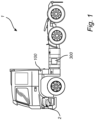
- Fig. 1 illustrates a vehicle in the form of a truck 1 comprising an engine 2 such as for example an internal combustion engine.
- the internal combustion engine may be e.g. a diesel engine or a gasoline engine or any other type of internal combustion engine.
- the truck 1 may be a hybrid electric vehicle.
- the truck 1 further comprises an exhaust gas aftertreatment system 300 including e.g. catalytic devices, urea injectors, and nitrogen oxide sensors, and will be discussed in further with reference to subsequent drawings.
- the truck 1 further comprises a control unit 100 that will also be discussed with reference to subsequent drawings.
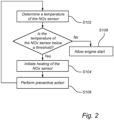
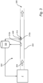
- Fig. 2 is a flow-chart of method steps according to embodiments of the invention and fig. 3 conceptually illustrates an exhaust aftertreatment system 300 according to embodiments of the invention.
- the exhaust aftertreatment system 300 comprises an exhaust pipe section 302 for transferring exhaust gas 304 towards an exhaust gas outlet 306.
- the exhaust pipe section 302 is part of a larger transfer system for transferring exhaust gas from the engine 2 to an exhaust gas outlet 306.
- the aftertreatment system 300 may comprise catalytic units (e.g. selective catalytic reduction devices), urea injectors, ammonia-slip catalysts, diesel oxidation catalyst, particulate filters, exhaust gas temperature sensors, and other components that are per se known to the skilled person and will not be described in detail herein.
- a NOx sensor 308 is arranged in the exhaust pipe section 302 for measuring a level of nitrogen oxides (NOx) in the exhaust gas 304. Further, a heater 312 is arranged to heat the NOx sensor 308.
- the NOx sensor 308 may comprise its own heater integrated with the NOx-sensor, or the heater is an external heater arranged in contact with the housing of the NOx sensor 308, or at least in close proximity to the NOx sensor 308, sufficiently close to be able to heat the NOx sensor 308 in accordance with embodiments herein.
- a single NOx sensor 308 is depicted. However, in practical applications, there is typically more than one NOx sensor in the aftertreatment system.
- a first NOx sensor may be arranged upstream of a selective catalytic reduction unit and a second NOx sensor may be arranged downstream of the selective catalytic reduction unit and possibly downstream of an ammonia-slip catalyst.
- the locations of the NOx sensors in the aftertreatment system depend on the specific implementation at hand and various possibilities exist and are within the scope of the invention.
- a temperature of the NOx sensor 308 is determined. This temperature may be determined by a temperature sensor arranged on and being dedicated to the NOx sensor. However, preferably, the NOx sensor 308 has its own internal circuitry and sensor 310a for determining its temperature, or at least whether it is ready for activation. In some possible implementations a sensor 310b arranged to measure the temperature of the exhaust gas in the transfer pipe 302 is located near the NOx sensor 308. In this way the temperature of the NOx sensor 308 can be estimated from the temperature measured by the sensor 310b, or the temperature measured by the sensor 310b can be used as an indication of the temperature of the NOx sensor 308.
- the temperature sensor of the NOX sensor may indicate that the measured temperature is below the predetermined threshold, whereby the heater 312 is responsive to initiate heating of the NOx sensor 308.
- a preventive action is performed for delaying engine start until a determined temperature of the NOx sensor 308 exceeds or is equal to a predetermined threshold.
- the system 300 further comprises a control unit 100 configured to cause the preventive action.
- the control unit 100 may prevent the engine 2 to start, i.e. the preventive action is a hard action forcing the engine 2 to continue to be off until the NOx sensor 308 is at its predefined temperature.
- the preventive action, caused by the control unit 100 is of a more instructive nature and comprises generating a signal with instructions informing the driver to delay starting the engine 2. The signal may be generated upon initiating heating of the NOx sensor 308.
- the preventive action could either be a "hard” prevention, where an engine control unit could inhibit start of the engine 2 before the NOx sensor 308 has reached the predetermined temperature and is active.
- the preventive action could also be a "soft” prevention action as a recommendation where the driver is requested to postpone or delay starting the engine 2 but also has the option to override the preventive function if needed, for example due to safety reasons if the vehicle is parked but quickly has to move, for example due to a hazard such as a fire nearby or another emergency situation.
- the preventive action may terminate and the engine is allowed to start, in step S108.
- the control unit 100 is, in one implementation, configured to receive signals from the internal temperature sensor 310a of the NOx sensor indicative of the temperature of the NOx sensor. In other possible implementations, the control unit 100 is configured to receive signals from the sensor 310b indicative of the temperature in the exhaust gas transfer pipe 302, here upstream of the NOx sensor 308, from which signals the control unit 100 can calculate or model the temperature of the NOx sensor 308. If the internal temperature sensor 310a of the NOx sensor is used, the sensor 310b may be omitted for the purpose of determining the temperature of the NOx sensor 308.
- cold start diagnostics and/or on-board monitoring of emissions can be initiated.
- the cold start diagnostics and/or on-board monitoring can be initiated and utilized with high accuracy from the instant that the engine 2 is started due to that the NOx sensor 308 will already be heated up and active.
- emission control may be improved during cold starts.
- the NOx sensor 308 may be activated when the measured temperature of the NOx sensor 308 exceeds or is equal to the predetermined threshold.
- the NOx sensor 308 itself may provide a signal to the control unit 100 that it is active and ready to provide NOx emission measurements data.
- the heater 312 is controllable by the control unit 100 to heat the NOx sensor 308 at a heating rate to vaporize water accumulated on the NOx sensor 308 such that damage to the NOx sensor 308 due to expanding water vapor is prevented.
- the heater 312 may comprise an electrical heating element or a heating element powered by the same fuel as the engine 2.
- an electrical heating element provides for a versatile heating element that can be used with almost any type of exhaust aftertreatment system since electric power sources are included in most vehicles.
- a heating element powered by the same fuel as the engine eliminates the need for an electrical power source, thus saving energy in the electrical energy sources of the vehicle that may be used for other systems in need of electrical energy.
- a diesel driven burner, or a hydrogen driven heater may be used, or a heater using some other type of available chemical fuel.
- an air pump in the exhaust aftertreatment system may be used to increase the air flow going through the system for heating the NOx sensor, possibly in combination with one or more of the other mentioned types of heaters.
- the control unit 100 is configured for controlling NOx emission during start of a vehicle 1 comprising an exhaust aftertreatment system 300 and a NOx sensor 308.
- the control unit 100 being is configured to determine a temperature of the NOx sensor 308 by acquired sensing data from a temperature sensor 310a of the NOX sensor 308 or from a sensor 310b in the exhaust aftertreatment system, or by receiving a signal from the NOx sensor 308 itself indicative of the present state of the NOx sensor. If the determined temperature of the NOx sensor 308 is below a predetermined threshold and thus needs heating, the control unit 100 is configured to initiate heating of the NOx sensor 308. If the heating is initiated, the control unit 100 is configured to control a preventive action for delaying engine start until the temperature of the NOx sensor is determined to exceed or being equal to the predetermined threshold.
- a control unit may include a microprocessor, microcontroller, programmable digital signal processor or another programmable device.
- the control unit comprises electronic circuits and connections (not shown) as well as processing circuitry (not shown) such that the control unit can communicate with different parts of the truck such as the brakes, suspension, driveline, in particular an electrical engine, an electric machine, a clutch, and a gearbox in order to at least partly operate the truck.
- the control unit may comprise modules in either hardware or software, or partially in hardware or software and communicate using known transmission buses such as CAN-bus and/or wireless communication capabilities.
- the processing circuitry may be a general-purpose processor or a specific processor.
- the control unit comprises a non-transitory memory for storing computer program code and data upon. Thus, the skilled addressee realizes that the control unit may be embodied by many different constructions.
- control functionality of the present disclosure may be implemented using existing computer processors, or by a special purpose computer processor for an appropriate system, incorporated for this or another purpose, or by a hardwire system.
- Embodiments within the scope of the present disclosure include program products comprising machine-readable medium for carrying or having machine-executable instructions or data structures stored thereon.
- Such machine-readable media can be any available media that can be accessed by a general purpose or special purpose computer or other machine with a processor.
- machine-readable media can comprise RAM, ROM, EPROM, EEPROM, CD-ROM or other optical disk storage, magnetic disk storage or other magnetic storage devices, or any other medium which can be used to carry or store desired program code in the form of machine-executable instructions or data structures and which can be accessed by a general purpose or special purpose computer or other machine with a processor.
- a network or another communications connection either hardwired, wireless, or a combination of hardwired or wireless
- any such connection is properly termed a machine-readable medium.
- Machine-executable instructions include, for example, instructions and data which cause a general-purpose computer, special purpose computer, or special purpose processing machines to perform a certain function or group of functions.
Description
- The present disclosure relates to a method for NOx emission control during start of a vehicle comprising an exhaust aftertreatment system, an engine, and a NOx sensor. The present disclosure also relates to a corresponding exhaust aftertreatment system. Although the method and system will be described in relation to a vehicle in the form of a truck, the method and system can also be efficiently incorporated in other vehicles types such as e.g. buses and construction equipment.
- During cold starts of vehicles, it is difficult to control NOx emissions which tend to be higher at cold starts. NOx emission control performed by cold start On Board Diagnostics (OBD) and On Board monitoring (OBM) processes relies on measurements performed by NOx sensors in the exhaust aftertreatment systems of the vehicle.
- To perform On Board Diagnostics of NOx emissions during a cold start is challenging since the NOx sensors require time to warm up and start before they can provide accurate readings. The current NOx sensors are sensitive to humidity and therefore starting the sensor is typically delayed until water on the sensor has vaporized. However, by the time the NOx sensor is warmed up, the cold start sequence of the vehicle is nearly ended and the opportunity to perform emission control and diagnostics during the cold start is lost or at least cannot be optimally performed.
- A prior art example is disclosed in
DE102012205017 which describes a method involving detecting a trigger event to activate a heating element before activating an internal combustion engine. The heating element is activated for heating a ceramic sensor element at pre-heating. A further example is described inWO2006117357 including a method for heating a lambda probe before the internal combustion engine is started. - Emission control, diagnostics, and monitoring have attracted much attention due to the environmental impact of emissions. Therefore, at least for this reason, it is of interest to improve such emission control, especially during cold starts.
- An object of the invention is to provide a method and system for NOx emission control during start of a vehicle that at least partly alleviates the deficiencies with the prior art.
- According to a first aspect of the invention, the object is achieved by a method according to
claim 1. - The preventive action is performed to directly or indirectly cause a delay in starting the engine so that the NOx sensor is allowed sufficient time to heat up to a temperature that ensure proper operation of the NOx sensor. Once sufficiently warm, the NOx sensor can provide accurate emission level measurements during the engine cold start.
- Once the temperature of the NOx sensor is determined, or estimated, to be equal to or exceed the predetermined threshold, the preventive action may be terminated.
- NOx sensors are commonly used in exhaust gas aftertreatment systems of vehicles and are configured to detect and measure the levels of nitrogen oxides in the exhaust gas. NOx sensors are considered known per se and details about their operation and functionality will not be described in detail herein.
- The engine is preferably an internal combustion engine. The internal combustion engine may be diesel engine or a gasoline engine or any other type of internal combustion engine. The internal combustion engine may be part of a hybrid driveline partly powered by a battery.
- According to the invention, performing a preventive action comprises preventing the engine to start. This preventive action is such that even if an occupant of the vehicle attempts to start the engine, the engine will not start and is thus forced to maintain off. Thus, engine start, e.g. ignition, is not allowed until the NOx-sensor is sufficiently warm. This ensures that the NOx-sensor has reached proper operating temperature and can provide accurate measurements.
- According to an example embodiment, performing a preventive action may comprise generating a signal with instructions informing the driver to delay starting the engine. Thus, the preventive action may be a message encouraging the driver to delay engine start. The instructions may be provided as a message in the form of a "pop-up" message in the driver interface. It could also be an information message using audio, or with a lamp lighting up in the driver interface. It could potentially also be a combination of the different types of messages. With a less forcing preventive action the driver may override the prevention in case of e.g. emergencies.
- According to an example embodiment, the signal with instructions informing the driver to delay starting the engine may be generated upon initiating heating of the NOx sensor. Hereby, a confirmation that NOx sensor heating is initiated is provided which allows for better timing of other tasks by the user. The instructions may for example include information about how long the delay to engine start is expected to be.
- According to an example embodiment, the method may comprise initiating cold start on board diagnostics and/or on-board monitoring once the engine is started. Generally, when the engine and aftertreatment system is cold and the engine starts, the exhaust emissions are higher than when the system and engine have heated up. This is due to that NOx conversion in the aftertreatment system requires relatively high exhaust gas temperatures to work efficiently. Early initiation of cold start diagnostics and/or on-board monitoring advantageously provides for efficient monitoring of cold start emissions. In this way, any potential faults can be detected quickly by analysing the NOx levels. Further, monitoring the cold start NOx emissions over time may be advantageous since it allows for tracking cold start performances of the vehicles during their complete lifetime. For example, this enables detecting and tracking aging of the exhaust aftertreatment systems.
- According to an example embodiment, the method may further comprise activating the NOx sensor when the measured temperature of the NOx sensor exceeds or is equal to the predetermined threshold. To activate the NOx sensor means that the sensor can start to send useful measurement values to an engine control unit. The NOx sensor element needs to be relatively warm, e.g. approximately 800°C to work efficiently. When the NOx sensor is activated and sending useful measurement values, these values can be used by the control systems to convert NOx with as high performance as possible, or at least with an acceptable level of performance.
- Heating of the NOx sensor is performed in a controlled way at a heating rate that is sufficiently low to not damage the sensor or cause unnecessary wear and tear on the NOx sensor.
- According to an example embodiment, heating of the NOx sensor may be performed such that water accumulated on the NOx sensor is vaporized in a controlled way so that damage to the NOx sensor due to expanding water vapor is prevented. Thus, heating of the NOx sensor is performed at a slow rate so that the heating does not cause damage to the NOx sensor. The heating rate is such that the water on the sensor can vaporize out and away from the sensor at a rate such that the expansion thereof does not cause damage to the NOx sensor. For example, the NOx sensor is heated to about 800°C in about 10-60 seconds depending on the surrounding temperature.
- According to a second aspect of the invention, the object is achieved by a system according to claim 7.
- According to the second aspect of the invention, there is provided an exhaust aftertreatment system of a vehicle comprising: an exhaust pipe section for transferring exhaust gas towards an exhaust gas outlet; a NOx sensor arranged in the exhaust pipe for measuring a level of nitrogen oxides in the exhaust gas; a heater arranged to heat the NOx sensor, and a sensor for determining a temperature of the NOx sensor; and the system further comprising a control unit configured to cause a preventive action for preventing engine start until a determined temperature of the NOx sensor exceeds or is equal to the predetermined threshold.
- According to an example embodiment, the control unit may be configured to prevent the vehicle to start until the determined temperature of the NOx sensor exceeds the threshold, and/or to generate a signal with instructions informing the driver to delay starting the engine. According to an example embodiment, the heater may be controllable to heat the NOx sensor at a heating rate to vaporize water accumulated on the NOx sensor such that damage to the NOx sensor due to expanding water vapor is prevented.
- According to an example embodiment, the heater comprises an electrical heating element or a heating element powered by the same type of fuel as the engine.
- Effects and features of the second aspect of the invention are largely analogous to those described above in connection with the first aspect.
- According to a third aspect of the invention, there is provided a vehicle comprising the exhaust aftertreatment system according to the second aspect.
- According to a fourth aspect of the invention, there is provided a computer program comprising program code means for performing the steps of the first aspect when the program is run on a computer.
- According to a fifth aspect of the invention, there is provided a computer readable medium carrying a computer program comprising program code means for performing the steps of the first aspect when the program product is run on a computer.
- According to a sixth aspect of the invention, there is provided a control unit for controlling NOx emission during start of a vehicle comprising an exhaust aftertreatment system and a NOx sensor, the control unit being configured to perform the steps of the method according to the first aspect.
- Effects and features of the third, fourth, fifth, and sixth aspects are largely analogous to those described above in relation to the first aspect.
- Further features of, and advantages will become apparent when studying the appended claims and the following description. The skilled person will realize that different features may be combined to create embodiments other than those described in the following, without departing from the scope of the appended claims.
- With reference to the appended drawings, below follows a more detailed description of embodiments of the invention cited as examples.
- In the drawings:
-
Fig. 1 is a vehicle in the form a truck according to example embodiments of the invention; -
Fig. 2 is a flow-chart of method steps according to example embodiments of the invention; and -
Fig. 3 is a schematic illustration of a system according to example embodiments of the invention. - The present invention will now be described more fully hereinafter with reference to the accompanying drawings, in which exemplary embodiments of the invention are shown. The invention may, however, be embodied in many different forms and should not be construed as limited to the embodiments set forth herein; rather, these embodiments are provided for thoroughness and completeness. The skilled person will recognize that many changes and modifications may be made within the scope of the appended claims.
- Like reference character refer to like elements throughout the description.
-
Fig. 1 illustrates a vehicle in the form of atruck 1 comprising anengine 2 such as for example an internal combustion engine. The internal combustion engine may be e.g. a diesel engine or a gasoline engine or any other type of internal combustion engine. Thetruck 1 may be a hybrid electric vehicle. Thetruck 1 further comprises an exhaustgas aftertreatment system 300 including e.g. catalytic devices, urea injectors, and nitrogen oxide sensors, and will be discussed in further with reference to subsequent drawings. Thetruck 1 further comprises acontrol unit 100 that will also be discussed with reference to subsequent drawings. -
Fig. 2 is a flow-chart of method steps according to embodiments of the invention andfig. 3 conceptually illustrates anexhaust aftertreatment system 300 according to embodiments of the invention. - The
exhaust aftertreatment system 300 comprises anexhaust pipe section 302 for transferringexhaust gas 304 towards anexhaust gas outlet 306. Theexhaust pipe section 302 is part of a larger transfer system for transferring exhaust gas from theengine 2 to anexhaust gas outlet 306. Generally, theaftertreatment system 300 may comprise catalytic units (e.g. selective catalytic reduction devices), urea injectors, ammonia-slip catalysts, diesel oxidation catalyst, particulate filters, exhaust gas temperature sensors, and other components that are per se known to the skilled person and will not be described in detail herein. - A
NOx sensor 308 is arranged in theexhaust pipe section 302 for measuring a level of nitrogen oxides (NOx) in theexhaust gas 304. Further, aheater 312 is arranged to heat theNOx sensor 308. TheNOx sensor 308 may comprise its own heater integrated with the NOx-sensor, or the heater is an external heater arranged in contact with the housing of theNOx sensor 308, or at least in close proximity to theNOx sensor 308, sufficiently close to be able to heat theNOx sensor 308 in accordance with embodiments herein. - Here, a
single NOx sensor 308 is depicted. However, in practical applications, there is typically more than one NOx sensor in the aftertreatment system. For example, a first NOx sensor may be arranged upstream of a selective catalytic reduction unit and a second NOx sensor may be arranged downstream of the selective catalytic reduction unit and possibly downstream of an ammonia-slip catalyst. - The locations of the NOx sensors in the aftertreatment system depend on the specific implementation at hand and various possibilities exist and are within the scope of the invention.
- In step S102, a temperature of the
NOx sensor 308 is determined. This temperature may be determined by a temperature sensor arranged on and being dedicated to the NOx sensor. However, preferably, theNOx sensor 308 has its own internal circuitry andsensor 310a for determining its temperature, or at least whether it is ready for activation. In some possible implementations asensor 310b arranged to measure the temperature of the exhaust gas in thetransfer pipe 302 is located near theNOx sensor 308. In this way the temperature of theNOx sensor 308 can be estimated from the temperature measured by thesensor 310b, or the temperature measured by thesensor 310b can be used as an indication of the temperature of theNOx sensor 308. - It is next evaluated whether the determined temperature of the
NOx sensor 308 is below a predetermined threshold, and if so, initiating heating of theNOx sensor 308 in step S104. Thus, the temperature sensor of the NOX sensor may indicate that the measured temperature is below the predetermined threshold, whereby theheater 312 is responsive to initiate heating of theNOx sensor 308. - Further, in step S106 a preventive action is performed for delaying engine start until a determined temperature of the
NOx sensor 308 exceeds or is equal to a predetermined threshold. For this, thesystem 300 further comprises acontrol unit 100 configured to cause the preventive action. For example, thecontrol unit 100 may prevent theengine 2 to start, i.e. the preventive action is a hard action forcing theengine 2 to continue to be off until theNOx sensor 308 is at its predefined temperature. In other embodiments, the preventive action, caused by thecontrol unit 100 is of a more instructive nature and comprises generating a signal with instructions informing the driver to delay starting theengine 2. The signal may be generated upon initiating heating of theNOx sensor 308. - Thus, the preventive action could either be a "hard" prevention, where an engine control unit could inhibit start of the
engine 2 before theNOx sensor 308 has reached the predetermined temperature and is active. The preventive action could also be a "soft" prevention action as a recommendation where the driver is requested to postpone or delay starting theengine 2 but also has the option to override the preventive function if needed, for example due to safety reasons if the vehicle is parked but quickly has to move, for example due to a hazard such as a fire nearby or another emergency situation. - Once the temperature of the
NOx sensor 308 is determined, or estimated, to be equal to or exceed the predetermined threshold, the preventive action may terminate and the engine is allowed to start, in step S108. - The
control unit 100 is, in one implementation, configured to receive signals from theinternal temperature sensor 310a of the NOx sensor indicative of the temperature of the NOx sensor. In other possible implementations, thecontrol unit 100 is configured to receive signals from thesensor 310b indicative of the temperature in the exhaustgas transfer pipe 302, here upstream of theNOx sensor 308, from which signals thecontrol unit 100 can calculate or model the temperature of theNOx sensor 308. If theinternal temperature sensor 310a of the NOx sensor is used, thesensor 310b may be omitted for the purpose of determining the temperature of theNOx sensor 308. - Once the
engine 2 is started cold start diagnostics and/or on-board monitoring of emissions can be initiated. With the method proposed herein, the cold start diagnostics and/or on-board monitoring can be initiated and utilized with high accuracy from the instant that theengine 2 is started due to that theNOx sensor 308 will already be heated up and active. Thus, emission control may be improved during cold starts. TheNOx sensor 308 may be activated when the measured temperature of theNOx sensor 308 exceeds or is equal to the predetermined threshold. TheNOx sensor 308 itself may provide a signal to thecontrol unit 100 that it is active and ready to provide NOx emission measurements data. - The
heater 312 is controllable by thecontrol unit 100 to heat theNOx sensor 308 at a heating rate to vaporize water accumulated on theNOx sensor 308 such that damage to theNOx sensor 308 due to expanding water vapor is prevented. - The
heater 312 may comprise an electrical heating element or a heating element powered by the same fuel as theengine 2. Using an electrical heating element provides for a versatile heating element that can be used with almost any type of exhaust aftertreatment system since electric power sources are included in most vehicles. However, using a heating element powered by the same fuel as the engine eliminates the need for an electrical power source, thus saving energy in the electrical energy sources of the vehicle that may be used for other systems in need of electrical energy. For example, a diesel driven burner, or a hydrogen driven heater may be used, or a heater using some other type of available chemical fuel. Further, an air pump in the exhaust aftertreatment system may be used to increase the air flow going through the system for heating the NOx sensor, possibly in combination with one or more of the other mentioned types of heaters. - The
control unit 100 is configured for controlling NOx emission during start of avehicle 1 comprising anexhaust aftertreatment system 300 and aNOx sensor 308. Thecontrol unit 100 being is configured to determine a temperature of theNOx sensor 308 by acquired sensing data from atemperature sensor 310a of theNOX sensor 308 or from asensor 310b in the exhaust aftertreatment system, or by receiving a signal from theNOx sensor 308 itself indicative of the present state of the NOx sensor. If the determined temperature of theNOx sensor 308 is below a predetermined threshold and thus needs heating, thecontrol unit 100 is configured to initiate heating of theNOx sensor 308. If the heating is initiated, thecontrol unit 100 is configured to control a preventive action for delaying engine start until the temperature of the NOx sensor is determined to exceed or being equal to the predetermined threshold. - A control unit may include a microprocessor, microcontroller, programmable digital signal processor or another programmable device. Thus, the control unit comprises electronic circuits and connections (not shown) as well as processing circuitry (not shown) such that the control unit can communicate with different parts of the truck such as the brakes, suspension, driveline, in particular an electrical engine, an electric machine, a clutch, and a gearbox in order to at least partly operate the truck. The control unit may comprise modules in either hardware or software, or partially in hardware or software and communicate using known transmission buses such as CAN-bus and/or wireless communication capabilities. The processing circuitry may be a general-purpose processor or a specific processor. The control unit comprises a non-transitory memory for storing computer program code and data upon. Thus, the skilled addressee realizes that the control unit may be embodied by many different constructions.
- The control functionality of the present disclosure may be implemented using existing computer processors, or by a special purpose computer processor for an appropriate system, incorporated for this or another purpose, or by a hardwire system. Embodiments within the scope of the present disclosure include program products comprising machine-readable medium for carrying or having machine-executable instructions or data structures stored thereon. Such machine-readable media can be any available media that can be accessed by a general purpose or special purpose computer or other machine with a processor. By way of example, such machine-readable media can comprise RAM, ROM, EPROM, EEPROM, CD-ROM or other optical disk storage, magnetic disk storage or other magnetic storage devices, or any other medium which can be used to carry or store desired program code in the form of machine-executable instructions or data structures and which can be accessed by a general purpose or special purpose computer or other machine with a processor. When information is transferred or provided over a network or another communications connection (either hardwired, wireless, or a combination of hardwired or wireless) to a machine, the machine properly views the connection as a machine-readable medium. Thus, any such connection is properly termed a machine-readable medium. Combinations of the above are also included within the scope of machine-readable media. Machine-executable instructions include, for example, instructions and data which cause a general-purpose computer, special purpose computer, or special purpose processing machines to perform a certain function or group of functions.
- Although the figures may show a sequence the order of the steps may differ from what is depicted. Also, two or more steps may be performed concurrently or with partial concurrence. Such variation will depend on the software and hardware systems chosen and on designer choice. All such variations are within the scope of the disclosure. Likewise, software implementations could be accomplished with standard programming techniques with rule-based logic and other logic to accomplish the various connection steps, processing steps, comparison steps and decision steps.
- It is to be understood that the present invention is not limited to the embodiments described above and illustrated in the drawings; rather, the skilled person will recognize that many changes and modifications may be made within the scope of the appended claims.
Claims (14)
- A method for NOx emission control during start of a vehicle (1) comprising an exhaust aftertreatment system (300), an engine (2), and a NOx sensor (308), the method being characterized by the steps of:determining (S102) a temperature of the NOx sensor;if the determined temperature of the NOx sensor is below a predetermined threshold, initiating (S104) heating of the NOx sensor, andperforming (S106) a preventive action for preventing engine start until the determined temperature of the NOx sensor exceeds or is equal to the predetermined threshold.
- The method according to claim 1, wherein performing a preventive action comprises generating a signal with instructions informing the driver to delay starting the engine (2).
- The method according to claim 2, wherein the signal is generated upon initiating heating of the NOx sensor (308).
- The method according to any one of the preceding claims, comprising initiating cold start on board diagnostics and/or on-board monitoring once the engine (2) is started.
- The method according to any one of the preceding claims, further comprising activating the NOx sensor when the determined temperature of the NOx sensor exceeds or is equal to the predetermined threshold.
- The method according to any one of the preceding claims, wherein heating of the NOx sensor (308) is performed such that water accumulated on the NOx sensor is vaporized in a controlled way so that damage to the NOx sensor (308) due to expanding water vapor is prevented.
- An exhaust aftertreatment system (300) of a vehicle (1) comprising:an exhaust pipe section (302) for transferring exhaust gas (304) towards an exhaust gas outlet (306);a NOx sensor (308) arranged in the exhaust pipe for measuring a level of nitrogen oxides (NOx) in the exhaust gas;a heater (312) arranged to heat the NOx sensor, anda sensor (310a; 310b) for determining a temperature of the NOx sensor; andthe system being characterised by a control unit (100) configured to cause a preventive action for preventing engine start until a determined temperature of the NOx sensor exceeds or is equal to the predetermined threshold.
- The exhaust aftertreatment system according to claim 7, wherein the control unit is configured to generate a signal with instructions informing the driver to delay starting the engine (2).
- The exhaust aftertreatment system according to anyone of claims 7 and 8, wherein the heater is controllable to heat the NOx sensor at a heating rate to vaporize water accumulated on the NOx sensor such that damage to the NOx sensor due to expanding water vapor is prevented.
- The exhaust aftertreatment system according to any one of claims 7 to 9, wherein the heater (312) comprises an electrical heating element or a heating element powered by the same type of fuel as the engine (2).
- A vehicle (1) comprising an exhaust aftertreatment system (300) according to any one of claims 7 to 10.
- A computer program comprising program code means for performing the steps of any of claims 1-6 when said program is run on a computer.
- A computer readable medium carrying a computer program comprising program code means for performing the steps of any of claims 1-6 when said program product is run on a computer.
- A control unit (100) for controlling NOx emission during start of a vehicle comprising an exhaust aftertreatment system, an engine and a NOx sensor, the control unit being configured to perform the steps of the method according to any of claims 1-6.
Priority Applications (4)
| Application Number | Priority Date | Filing Date | Title |
|---|---|---|---|
| EP21183463.5A EP4112899B1 (en) | 2021-07-02 | 2021-07-02 | Controlling nox emission control during start of a vehicle |
| CN202210654052.5A CN115559805A (en) | 2021-07-02 | 2022-06-10 | Controlling NOx emissions control during vehicle launch |
| JP2022099574A JP2023008849A (en) | 2021-07-02 | 2022-06-21 | Nox emission suppression control during start-up of vehicle |
| US17/808,213 US11686237B2 (en) | 2021-07-02 | 2022-06-22 | Controlling NOx emission control during start of a vehicle |
Applications Claiming Priority (1)
| Application Number | Priority Date | Filing Date | Title |
|---|---|---|---|
| EP21183463.5A EP4112899B1 (en) | 2021-07-02 | 2021-07-02 | Controlling nox emission control during start of a vehicle |
Publications (3)
| Publication Number | Publication Date |
|---|---|
| EP4112899A1 EP4112899A1 (en) | 2023-01-04 |
| EP4112899B1 true EP4112899B1 (en) | 2023-12-27 |
| EP4112899C0 EP4112899C0 (en) | 2023-12-27 |
Family
ID=76764923
Family Applications (1)
| Application Number | Title | Priority Date | Filing Date |
|---|---|---|---|
| EP21183463.5A Active EP4112899B1 (en) | 2021-07-02 | 2021-07-02 | Controlling nox emission control during start of a vehicle |
Country Status (4)
| Country | Link |
|---|---|
| US (1) | US11686237B2 (en) |
| EP (1) | EP4112899B1 (en) |
| JP (1) | JP2023008849A (en) |
| CN (1) | CN115559805A (en) |
Family Cites Families (8)
| Publication number | Priority date | Publication date | Assignee | Title |
|---|---|---|---|---|
| US6481428B1 (en) * | 2000-10-13 | 2002-11-19 | Ford Global Technologies, Inc. | Methods and systems for reducing internal combustion engine exhaust emissions |
| DE102005020363A1 (en) * | 2005-05-02 | 2006-11-16 | Robert Bosch Gmbh | Device and method for operating a sensor for gases, in particular a lambda probe |
| DE102012205017A1 (en) * | 2011-04-28 | 2012-10-31 | Robert Bosch Gmbh | Method for operating internal combustion engine, involves detecting trigger event to activate heating element before activating internal combustion engine, where heating element is activated for heating ceramic sensor element |
| DE102016200721A1 (en) * | 2016-01-20 | 2017-07-20 | Robert Bosch Gmbh | Method for monitoring NOx sensors |
| DE102017107678A1 (en) | 2017-04-10 | 2018-10-11 | Volkswagen Aktiengesellschaft | Method for starting up an internal combustion engine and motor vehicle with an internal combustion engine |
| SE542332C2 (en) | 2018-04-24 | 2020-04-14 | Scania Cv Ab | Method and system for control of an activation of at least one liquid sensitive sensor |
| DE102019203598A1 (en) * | 2019-03-18 | 2020-09-24 | Robert Bosch Gmbh | Method for operating a motor vehicle |
| DE102019126613A1 (en) * | 2019-10-02 | 2019-11-21 | FEV Group GmbH | Internal combustion engine |
-
2021
- 2021-07-02 EP EP21183463.5A patent/EP4112899B1/en active Active
-
2022
- 2022-06-10 CN CN202210654052.5A patent/CN115559805A/en active Pending
- 2022-06-21 JP JP2022099574A patent/JP2023008849A/en active Pending
- 2022-06-22 US US17/808,213 patent/US11686237B2/en active Active
Also Published As
| Publication number | Publication date |
|---|---|
| JP2023008849A (en) | 2023-01-19 |
| US11686237B2 (en) | 2023-06-27 |
| US20230003163A1 (en) | 2023-01-05 |
| CN115559805A (en) | 2023-01-03 |
| EP4112899C0 (en) | 2023-12-27 |
| EP4112899A1 (en) | 2023-01-04 |
Similar Documents
| Publication | Publication Date | Title |
|---|---|---|
| US10513961B2 (en) | NOx offset diagnostic during engine soak | |
| CN109695529B (en) | Method for heating exhaust gas aftertreatment system and hybrid vehicle | |
| US8042326B2 (en) | Intake air heater for assisting DPF regeneration | |
| US6971230B1 (en) | Method for the post-treatment of exhaust gases by subsequent injection of fuel in a diesel-type internal combustion engine provided with a pre-catalyst and a particle filter | |
| US8978370B2 (en) | Engine off particulate filter (“PF”) regeneration using a single secondary energy storage device | |
| JP2861628B2 (en) | Exhaust gas purification device | |
| JP4535036B2 (en) | Power supply system for internal combustion engine | |
| US8881504B2 (en) | System for providing power to an electrically heated catalyst | |
| US7558668B2 (en) | Exhaust system having temperature sensor verification | |
| US11060473B2 (en) | Method for commissioning an internal combustion engine, and motor vehicle comprising an internal combustion engine | |
| JP2006250134A (en) | Vehicular control device | |
| EP3688290B1 (en) | Method for operating a catalyst arrangement of an internal combustion engine and catalyst arrangement | |
| US20130291515A1 (en) | Engine Off Particulate Filter ("PF") Regeneration Using a Plurality of Secondary Energy Storage Devices | |
| JPH10238339A (en) | Exhaust emission control device | |
| CN109322728B (en) | Post-treatment heating method | |
| JP2021110302A (en) | Exhaust emission control device of internal combustion engine | |
| JPH04276111A (en) | Power supply of catalyzer with heater | |
| EP4112899B1 (en) | Controlling nox emission control during start of a vehicle | |
| CA3125388A1 (en) | Ammonia storage capacity of scr catalyst unit | |
| KR20180021653A (en) | Method and device for sequential control of an exhaust gas control system | |
| EP1876334B1 (en) | An exhaust gas temperature sensor inspecting apparatus | |
| TW201102296A (en) | Vehicle idle stop control device and control setting method | |
| US9250156B2 (en) | Techniques for evaluating performance of internal combustion engine components | |
| EP2687708A1 (en) | System for controlling an exhaust gas after-treatment system temperature of a combustion engine | |
| JP3216265B2 (en) | Catalyst activation determination device |
Legal Events
| Date | Code | Title | Description |
|---|---|---|---|
| PUAI | Public reference made under article 153(3) epc to a published international application that has entered the european phase |
Free format text: ORIGINAL CODE: 0009012 |
|
| STAA | Information on the status of an ep patent application or granted ep patent |
Free format text: STATUS: THE APPLICATION HAS BEEN PUBLISHED |
|
| AK | Designated contracting states |
Kind code of ref document: A1 Designated state(s): AL AT BE BG CH CY CZ DE DK EE ES FI FR GB GR HR HU IE IS IT LI LT LU LV MC MK MT NL NO PL PT RO RS SE SI SK SM TR |
|
| STAA | Information on the status of an ep patent application or granted ep patent |
Free format text: STATUS: REQUEST FOR EXAMINATION WAS MADE |
|
| 17P | Request for examination filed |
Effective date: 20230620 |
|
| GRAP | Despatch of communication of intention to grant a patent |
Free format text: ORIGINAL CODE: EPIDOSNIGR1 |
|
| RBV | Designated contracting states (corrected) |
Designated state(s): AL AT BE BG CH CY CZ DE DK EE ES FI FR GB GR HR HU IE IS IT LI LT LU LV MC MK MT NL NO PL PT RO RS SE SI SK SM TR |
|
| STAA | Information on the status of an ep patent application or granted ep patent |
Free format text: STATUS: GRANT OF PATENT IS INTENDED |
|
| RIC1 | Information provided on ipc code assigned before grant |
Ipc: F02N 11/10 20060101ALI20230707BHEP Ipc: F02D 41/14 20060101ALI20230707BHEP Ipc: F01N 11/00 20060101ALI20230707BHEP Ipc: F01N 9/00 20060101AFI20230707BHEP |
|
| INTG | Intention to grant announced |
Effective date: 20230727 |
|
| GRAS | Grant fee paid |
Free format text: ORIGINAL CODE: EPIDOSNIGR3 |
|
| GRAA | (expected) grant |
Free format text: ORIGINAL CODE: 0009210 |
|
| STAA | Information on the status of an ep patent application or granted ep patent |
Free format text: STATUS: THE PATENT HAS BEEN GRANTED |
|
| AK | Designated contracting states |
Kind code of ref document: B1 Designated state(s): AL AT BE BG CH CY CZ DE DK EE ES FI FR GB GR HR HU IE IS IT LI LT LU LV MC MK MT NL NO PL PT RO RS SE SI SK SM TR |
|
| REG | Reference to a national code |
Ref country code: GB Ref legal event code: FG4D |
|
| REG | Reference to a national code |
Ref country code: CH Ref legal event code: EP |
|
| REG | Reference to a national code |
Ref country code: DE Ref legal event code: R096 Ref document number: 602021008027 Country of ref document: DE |
|
| REG | Reference to a national code |
Ref country code: IE Ref legal event code: FG4D |
|
| U01 | Request for unitary effect filed |
Effective date: 20240123 |
|
| U07 | Unitary effect registered |
Designated state(s): AT BE BG DE DK EE FI FR IT LT LU LV MT NL PT SE SI Effective date: 20240131 |
|
| PG25 | Lapsed in a contracting state [announced via postgrant information from national office to epo] |
Ref country code: GR Free format text: LAPSE BECAUSE OF FAILURE TO SUBMIT A TRANSLATION OF THE DESCRIPTION OR TO PAY THE FEE WITHIN THE PRESCRIBED TIME-LIMIT Effective date: 20240328 |