EP4112869A1 - Laser cladded shank adapter - Google Patents
Laser cladded shank adapter Download PDFInfo
- Publication number
- EP4112869A1 EP4112869A1 EP21183269.6A EP21183269A EP4112869A1 EP 4112869 A1 EP4112869 A1 EP 4112869A1 EP 21183269 A EP21183269 A EP 21183269A EP 4112869 A1 EP4112869 A1 EP 4112869A1
- Authority
- EP
- European Patent Office
- Prior art keywords
- laser cladding
- shank adapter
- cladding layer
- layer
- shank
- Prior art date
- Legal status (The legal status is an assumption and is not a legal conclusion. Google has not performed a legal analysis and makes no representation as to the accuracy of the status listed.)
- Withdrawn
Links
- 238000004372 laser cladding Methods 0.000 claims abstract description 84
- 239000010410 layer Substances 0.000 claims abstract description 83
- 238000005260 corrosion Methods 0.000 claims abstract description 30
- 230000007797 corrosion Effects 0.000 claims abstract description 30
- 238000000034 method Methods 0.000 claims abstract description 17
- 238000005553 drilling Methods 0.000 claims abstract description 9
- 239000002347 wear-protection layer Substances 0.000 claims abstract description 5
- 239000000463 material Substances 0.000 claims description 12
- 239000000203 mixture Substances 0.000 claims description 12
- NBIIXXVUZAFLBC-UHFFFAOYSA-K phosphate Chemical compound [O-]P([O-])([O-])=O NBIIXXVUZAFLBC-UHFFFAOYSA-K 0.000 claims description 12
- 229910019142 PO4 Inorganic materials 0.000 claims description 11
- 239000010452 phosphate Substances 0.000 claims description 11
- 239000011156 metal matrix composite Substances 0.000 claims description 7
- 229910001092 metal group alloy Inorganic materials 0.000 claims description 5
- 230000008021 deposition Effects 0.000 claims description 4
- 230000003746 surface roughness Effects 0.000 claims description 3
- 239000000758 substrate Substances 0.000 description 12
- VYZAMTAEIAYCRO-UHFFFAOYSA-N Chromium Chemical compound [Cr] VYZAMTAEIAYCRO-UHFFFAOYSA-N 0.000 description 9
- 238000011010 flushing procedure Methods 0.000 description 7
- 238000005253 cladding Methods 0.000 description 6
- 239000011435 rock Substances 0.000 description 6
- 229910045601 alloy Inorganic materials 0.000 description 5
- 239000000956 alloy Substances 0.000 description 5
- PXHVJJICTQNCMI-UHFFFAOYSA-N Nickel Chemical compound [Ni] PXHVJJICTQNCMI-UHFFFAOYSA-N 0.000 description 4
- 238000000576 coating method Methods 0.000 description 4
- 239000003973 paint Substances 0.000 description 4
- 238000007747 plating Methods 0.000 description 4
- 230000008569 process Effects 0.000 description 4
- 238000012545 processing Methods 0.000 description 4
- 239000011253 protective coating Substances 0.000 description 4
- XLYOFNOQVPJJNP-UHFFFAOYSA-N water Substances O XLYOFNOQVPJJNP-UHFFFAOYSA-N 0.000 description 4
- XEEYBQQBJWHFJM-UHFFFAOYSA-N Iron Chemical compound [Fe] XEEYBQQBJWHFJM-UHFFFAOYSA-N 0.000 description 3
- 230000008901 benefit Effects 0.000 description 3
- 239000011248 coating agent Substances 0.000 description 3
- 229910052751 metal Inorganic materials 0.000 description 3
- 239000002184 metal Substances 0.000 description 3
- 239000000843 powder Substances 0.000 description 3
- 239000011241 protective layer Substances 0.000 description 3
- 229910000831 Steel Inorganic materials 0.000 description 2
- 229910001315 Tool steel Inorganic materials 0.000 description 2
- -1 but not limited to Substances 0.000 description 2
- 239000011651 chromium Substances 0.000 description 2
- 230000008878 coupling Effects 0.000 description 2
- 238000010168 coupling process Methods 0.000 description 2
- 238000005859 coupling reaction Methods 0.000 description 2
- 230000003247 decreasing effect Effects 0.000 description 2
- 238000010790 dilution Methods 0.000 description 2
- 239000012895 dilution Substances 0.000 description 2
- 229910052759 nickel Inorganic materials 0.000 description 2
- 239000011148 porous material Substances 0.000 description 2
- 239000010935 stainless steel Substances 0.000 description 2
- 229910001220 stainless steel Inorganic materials 0.000 description 2
- 239000010959 steel Substances 0.000 description 2
- 238000012546 transfer Methods 0.000 description 2
- VEXZGXHMUGYJMC-UHFFFAOYSA-M Chloride anion Chemical compound [Cl-] VEXZGXHMUGYJMC-UHFFFAOYSA-M 0.000 description 1
- 229910018487 Ni—Cr Inorganic materials 0.000 description 1
- UCKMPCXJQFINFW-UHFFFAOYSA-N Sulphide Chemical compound [S-2] UCKMPCXJQFINFW-UHFFFAOYSA-N 0.000 description 1
- 230000009471 action Effects 0.000 description 1
- 239000011230 binding agent Substances 0.000 description 1
- 230000005540 biological transmission Effects 0.000 description 1
- 239000003795 chemical substances by application Substances 0.000 description 1
- 229910052804 chromium Inorganic materials 0.000 description 1
- 229910017052 cobalt Inorganic materials 0.000 description 1
- 239000010941 cobalt Substances 0.000 description 1
- GUTLYIVDDKVIGB-UHFFFAOYSA-N cobalt atom Chemical compound [Co] GUTLYIVDDKVIGB-UHFFFAOYSA-N 0.000 description 1
- 238000005336 cracking Methods 0.000 description 1
- 230000007423 decrease Effects 0.000 description 1
- 230000032798 delamination Effects 0.000 description 1
- 238000013461 design Methods 0.000 description 1
- 238000005265 energy consumption Methods 0.000 description 1
- 239000000835 fiber Substances 0.000 description 1
- 238000007542 hardness measurement Methods 0.000 description 1
- 230000003993 interaction Effects 0.000 description 1
- 150000002500 ions Chemical class 0.000 description 1
- 229910052742 iron Inorganic materials 0.000 description 1
- 238000004519 manufacturing process Methods 0.000 description 1
- 239000011159 matrix material Substances 0.000 description 1
- 238000010309 melting process Methods 0.000 description 1
- 239000002905 metal composite material Substances 0.000 description 1
- UNASZPQZIFZUSI-UHFFFAOYSA-N methylidyneniobium Chemical compound [Nb]#C UNASZPQZIFZUSI-UHFFFAOYSA-N 0.000 description 1
- NFFIWVVINABMKP-UHFFFAOYSA-N methylidynetantalum Chemical compound [Ta]#C NFFIWVVINABMKP-UHFFFAOYSA-N 0.000 description 1
- 150000004767 nitrides Chemical class 0.000 description 1
- 239000002245 particle Substances 0.000 description 1
- 238000009527 percussion Methods 0.000 description 1
- 230000002028 premature Effects 0.000 description 1
- 230000001681 protective effect Effects 0.000 description 1
- 239000000126 substance Substances 0.000 description 1
- 229910003468 tantalcarbide Inorganic materials 0.000 description 1
- MTPVUVINMAGMJL-UHFFFAOYSA-N trimethyl(1,1,2,2,2-pentafluoroethyl)silane Chemical compound C[Si](C)(C)C(F)(F)C(F)(F)F MTPVUVINMAGMJL-UHFFFAOYSA-N 0.000 description 1
- UONOETXJSWQNOL-UHFFFAOYSA-N tungsten carbide Chemical compound [W+]#[C-] UONOETXJSWQNOL-UHFFFAOYSA-N 0.000 description 1
Images

Classifications
-
- E—FIXED CONSTRUCTIONS
- E21—EARTH OR ROCK DRILLING; MINING
- E21B—EARTH OR ROCK DRILLING; OBTAINING OIL, GAS, WATER, SOLUBLE OR MELTABLE MATERIALS OR A SLURRY OF MINERALS FROM WELLS
- E21B17/00—Drilling rods or pipes; Flexible drill strings; Kellies; Drill collars; Sucker rods; Cables; Casings; Tubings
- E21B17/10—Wear protectors; Centralising devices, e.g. stabilisers
- E21B17/1085—Wear protectors; Blast joints; Hard facing
-
- B—PERFORMING OPERATIONS; TRANSPORTING
- B23—MACHINE TOOLS; METAL-WORKING NOT OTHERWISE PROVIDED FOR
- B23K—SOLDERING OR UNSOLDERING; WELDING; CLADDING OR PLATING BY SOLDERING OR WELDING; CUTTING BY APPLYING HEAT LOCALLY, e.g. FLAME CUTTING; WORKING BY LASER BEAM
- B23K26/00—Working by laser beam, e.g. welding, cutting or boring
- B23K26/34—Laser welding for purposes other than joining
-
- B—PERFORMING OPERATIONS; TRANSPORTING
- B23—MACHINE TOOLS; METAL-WORKING NOT OTHERWISE PROVIDED FOR
- B23K—SOLDERING OR UNSOLDERING; WELDING; CLADDING OR PLATING BY SOLDERING OR WELDING; CUTTING BY APPLYING HEAT LOCALLY, e.g. FLAME CUTTING; WORKING BY LASER BEAM
- B23K26/00—Working by laser beam, e.g. welding, cutting or boring
- B23K26/70—Auxiliary operations or equipment
-
- E—FIXED CONSTRUCTIONS
- E21—EARTH OR ROCK DRILLING; MINING
- E21B—EARTH OR ROCK DRILLING; OBTAINING OIL, GAS, WATER, SOLUBLE OR MELTABLE MATERIALS OR A SLURRY OF MINERALS FROM WELLS
- E21B17/00—Drilling rods or pipes; Flexible drill strings; Kellies; Drill collars; Sucker rods; Cables; Casings; Tubings
- E21B17/02—Couplings; joints
- E21B17/03—Couplings; joints between drilling rod or pipe and drill motor or surface drive, e.g. between drilling rod and hammer
-
- E—FIXED CONSTRUCTIONS
- E21—EARTH OR ROCK DRILLING; MINING
- E21B—EARTH OR ROCK DRILLING; OBTAINING OIL, GAS, WATER, SOLUBLE OR MELTABLE MATERIALS OR A SLURRY OF MINERALS FROM WELLS
- E21B17/00—Drilling rods or pipes; Flexible drill strings; Kellies; Drill collars; Sucker rods; Cables; Casings; Tubings
- E21B17/02—Couplings; joints
- E21B17/04—Couplings; joints between rod or the like and bit or between rod and rod or the like
- E21B17/042—Threaded
- E21B17/0426—Threaded with a threaded cylindrical portion, e.g. for percussion rods
Definitions
- the present invention relates to a shank adapter for top hammer rock drilling having a laser cladded corrosion and / or wear protection layer and a method of producing thereof.
- Shank adapters are used in rock drills as the main component which transfers the impact energy from the piston to the drill string while being rotated. Further, shank adapters are used to transfer flushing media from the rock drill into the drill string. Since shank adapters need to have high impact resistance, they are typically made from high strength carburized steel. However, the drawback of this material is that it is corroded by the flushing media, which may for example contain chloride, sulphide or other ions which accelerate the corrosion. If the shank adapter is corroded, its functionality decreases. The steel may for example have issues with stress corrosion cracking as the mechanical strength of the material is decreased.
- a known method of corrosion protection on shank adapters is to provide a hard chrome plating on its surface.
- hard chrome layers contain pores and microcracks which can act as channels for the water to penetrate through and reach the surface of the shank adapter therefore removing the corrosion protection.
- the process of applying the hard chrome layer has a high energy consumption and the hexavalent chrome used is harmful to the environment. Therefore, the problem to be solved is how to provide an alternative method of improving the corrosion and / or resistance of surfaces of the shank adapter.
- a shank adapter to form part of a drilling assembly, the shank adapter comprising: a longitudinal axis and an external surface; a threaded part provided at a forward end and a plurality of splines provided at a rearward end; and a machine part extending axially between the threaded part and the splines; characterised in that: at least a part of the external surface has at least one laser cladding layer for corrosion and / or wear protection.
- the laser cladding layer provides an alternative means of providing a corrosion protection layer to the surface of the shank adapter.
- the laser cladding provides a denser layer compared to a hard chrome layer and contains fewer pores and microcracks, therefore the longevity of the protective layer and the level of corrosion protection is increased. Furthermore, the wear resistance is improved and therefore the initial smooth surface finish provided is maintained which results in less wear on the contacting seals. If desired it is also possible to provide a coating on the laser cladding. Compared to chrome plating, the laser cladding will have better bonding to the substrate therefore reducing the risk of delamination of the protective later.
- the heat affected zone will not significantly impact the properties of the material in the substrate so that the mechanical integrity of the shank is maintained.
- the material used for the laser cladding can be selected to suit the properties required for specific application and drilling environments.
- the thickness of the laser cladding layer(s) is between 20 - 2000 ⁇ m.
- this thickness range provides an optimal balance between providing sufficient corrosion and wear protection without adding unnecessary cost and weight.
- the laser cladding layer(s) is /are applied such that the outer diameter of the section of the shank adapter where the laser cladding layer(s) has been applied is substantially uniform.
- this provides consistent corrosion and wear protection across the whole area of the external surface where the cladding is applied.
- the laser cladding layer(s) is / are positioned on the machine part.
- this is the section that is most subjected to corrosive attack and wear from seals interaction especially if water containing particles is used as flushing agent, therefore it is advantageous to provide the laser cladding in this region.
- the laser cladding layer(s) is / are positioned around a flush hole extends radially through the machine part.
- this provides corrosion / wear protection in the region that is most subjected to corrosive attack and wear.
- the shank adapter further comprises a layer of phosphate on top of the outermost laser cladding layer and a layer of wax on top of the layer of phosphate.
- this provides an additional corrosion protection during transportation for the shank adapter.
- the composition of the laser cladding layer comprises a metal matrix composite.
- the presence of the metal matrix composite increases the wear resistance of the laser cladding.
- the composition of the laser cladding layer comprises a metal alloy.
- the metal alloy can be selected having superior corrosion and /or wear resistance to suit the application.
- the laser cladding has a hardness of between 500 to 1800 HV30.Advantageously, this provides increased wear resistance.
- the outermost laser cladding layer has a surface roughness of ⁇ 3 Ra.
- this reduces the wear on the contacting seals.
- a method of providing corrosion protection on a shank adapter characterised in that: a corrosive and / or wear protection layer is applied to at least one part of the external surface(s) of the shank adapter using laser cladding.
- laser cladding is also more environmentally friendly compared to hard chrome plating as it is a less energy consumptive process and does not use any harmful chemicals. Further, laser cladding is a faster process compared to hard chrome plating, which is advantageous for production and produces a more reliable corrosion protection layer which will increase the lifetime of the shank adapter and other drilling components that attach to the shank adapter.
- the laser cladding is done using extreme high-speed laser (EHLA) material deposition.
- EHLA extreme high-speed laser
- EHLA provides thinner layers, with a reduced heat effected zone as the dilution between the cladding and the substrate is smaller, with higher power efficiency and faster processing times.
- the external surface of the shank adapter is ground and / or polished prior to application of the laser cladding layer(s).
- this increases the adhesion of the laser cladding corrosion protection layer to the external surface of the shank adapter.
- the outermost laser cladding layer is ground and / or polished.
- this reduces wear on the seals and therefore the lifetime of the product is increased and may reduce the area where possible cracks can be initiated from.
- the outermost laser cladding layer is coated in a layer of phosphate and then waxed.
- this provides transport protection for the laser cladding corrosion protection layer.
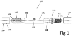
- FIG. 1 shows a shank adapter 100 comprising a machine part 101 (otherwise known as a main body ) having a forward end 103 and a rearward end 104, a longitudinal axis 109 and an external surface 102.
- a plurality of axially parallel elongate splines 106 project radially outward at the rearward end 104.
- the splines 106 are configured to be engaged by corresponding splines of drive bushing in a rotational motor (not shown) to induce rotation of the shank adaptor 100 about axis 109 during drilling operations.
- the shank adaptor 100 further comprises a flush hole (or bore) 105 positioned axially between the forward end 103 and the rearward end 104 that extends radially through the machine part 101 from the external surface 102 to an internal cavity or region extending axially within the shank adaptor 100.
- the shank adaptor 100 is configured for coupling to an elongate drill string and to allow transmission of a stress wave to a drill bit (not shown) located at the deepest region of the drill hole to impart the percussion drilling action.
- the forward end 103 may be coupled to a rearward end of a rearwardmost elongate drill rod 107 forming a part of the drill string or to a coupling (not shown) which is then connected to the drill rod 107.
- the rearward end 104 is configured to be contacted by a hydraulically driven piston 108 that creates the stress wave within the shank adaptor 100 and the drill string.
- the forward end 103 comprises a threaded part 112.
- the forward end 103 also comprises an annular shoulder 110 from which the threaded part 112 axially projects.
- the threaded part 112 could be either a male or female thread.
- a slim 111 is positioned axially between the machine part 101 and the threaded part 112.
- Figure 2 shows that at least a part of the external surface 102 has at least one laser cladding layer 114 applied thereon for corrosion and / or wear protection.
- the external surface 102 acts as a substrate for the laser cladding layer(s) 114.
- the thickness of the laser cladding layer(s) 114 is between 20 - 2000 ⁇ m, preferably between 20-1000 ⁇ m, more preferably 25-500 ⁇ m.
- the laser cladding layer(s) 114 is /are applied such that the outer diameter of the section of the shank adapter 100 where the laser cladding layer(s) 114 has been applied is substantially uniform.
- the laser cladding layer(s) 114 is / are positioned on the machine part 101.
- the laser cladding layer(s) 114 may be positioned over the entire external surface 102 of the machine part 101 or just part of it, for examples the regions of the machine part 101 that are most subjected to corrosion and / or wear.
- the laser cladding layer(s) 114 is / are positioned only on the machine part 101.
- the laser cladding layer(s) 114 is/are not positioned on the splines 106 or the threaded part 112.
- the laser cladding layer(s) 114 is positioned over the entire external surface 102 of the shank adapter 100.
- the laser cladding layer(s) 114 is / are positioned around or surrounding the flush hole 105 and / or the laser cladding layer(s) 114 is / are positioned on and / or near the regions of the machine part 101 that come into contact with the seals from rock drill.
- the positioning of the seals on the rock drill can vary depending on the design and the positioning of the laser cladding layer(s) 114 can be customised to correspond with the locations of the seals.
- Figure 3 shows that at least a part of the external surface 102 has at least one laser cladding layer 114 applied thereon and then preferably there is layer of phosphate 115 on top of the outermost laser cladding layer 114 and a layer of wax 116 on top of the layer of phosphate 115.
- Alternative protective coatings such as, but not limited to, oil or paint could be used instead of the wax.
- the shank adapter 100 may further comprise only a layer of phosphate 115 on top of the laser cladding layer(s) 114.
- the shank adapter 100 may further comprise only a layer of wax 116 or any other suitable protective coating such as oil or paint directly on top of the laser cladding 114.
- the composition of the laser cladding corrosion protection layer 114 comprises a metal matrix composite (MMC).
- MMC comprises a hard metal for example this could be tungsten carbide, titanium carbide, tantalum carbide, niobium carbide or any other carbide or nitride or a mixture thereof and a metal alloy as a binder which could for example comprise cobalt, nickel, iron, chromium or a mixture thereof.
- the composition of the laser cladding corrosion protection layer 114 comprises a metal alloy.
- the composition of the laser cladding material 114 could a stainless steel or tool steel.
- the composition of the laser cladding material 114 could for example be a nickel-based alloy e.g.
- Ni-Cr alloy a Ni-Cr alloy; an Fe based alloy; a Cr-based alloy; a mixture thereof or any other suitable material.
- the material selected can be chosen to suit the specific application and drilling environment, for example stainless steel will provide better corrosion protection, whereas tool steel or hard metal composite will provide better wear resistance.
- the laser cladding 114 has a hardness of between 180 to 1500 HV10, more preferably 400-1400 HV10 , even more preferably 500-1300 HV10.
- the coating is dense enough to prevent water from reaching the external surface 102 of the machine part 101. Hardness measurements are an average value for the cladded layer 114.
- the hardness of the metal matrix is 500-900 HV10, preferably 600-900 HV10, more preferably 600-900 HV10 and the hardness of the hard metal phase is 1500-3500 HV0.1, preferably 2000-3500 HV0.1 and most preferably 2500-3500 HV0.1.
- the outermost laser cladding layer 114 has a surface roughness of ⁇ 3 Ra, preferably ⁇ 2 Ra, more preferably ⁇ 1 Ra.
- Another aspect of the present invention is a method of providing corrosion protection on a shank adapter 100 wherein a corrosive and / or wear protection layer 114 is applied to at least one part of the external surface(s) 102 of the shank adapter (100) using laser cladding.
- the external surface 102 can also be considered to be the substrate for the laser cladding.
- Laser cladding is a melting process where a laser beam is used to fuse a powder alloy with another metallurgical composition onto a substrate. A metallic substrate is exposed to a laser beam while a powder is injected over the melted bath to form, after being solidified, a layer referred to as the cladding on the surface of the substrate.
- the key benefit is that only a very thin layer of the substrate has to be melted in order to achieve a metallurgical bond between the added material and the substrate.
- the laser cladding could be applied using a fiber, C02, YAG or diode laser or any other suitable laser.
- the laser cladding is done using extreme high-speed laser material deposition (EHLA).
- EHLA is a laser cladding method which is up to 10 times faster than traditional laser cladding methods in terms of surface coverage rate.
- the high-speed deposition from EHLA does not only result in a faster processing time, it also makes it possible to apply cladding to a substrate with even lower heat input and smaller distortion, meaning that the heat effected zone will be even less in the substrate.
- the small dilution formed by EHLA makes it possible to apply even thinner coatings, the thickness of the laser cladding layers is for example typically only 25-400 ⁇ m thick.
- the external surface 102 of the shank adapter 100 is ground and / or polished prior to application of the laser cladding layer(s) 114.
- the external surface 102 of the shank adapter 100 may be left unground, which has the advantage of quick processing time.
- the external surface 102 of the surface could be carburized and / or pre-heated prior to laser cladding.
- the outermost laser cladding layer 114 is ground and / or polished.
- the surface could be left unprocessed, which has the advantage of decreasing processing time.
- the outermost laser cladding layer 114 is coated in a layer of phosphate 115 and then coated in a layer of wax 116.
- Alternative protective coatings such as, but not limited to, oil or paint could be used instead of the wax.
- the outermost laser cladding layer 114 may be coated with only a layer of phosphate 115 or only with a layer of wax 116 or any other suitable protective coating such as oil or paint directly on top of the laser cladding 114.
Landscapes
- Engineering & Computer Science (AREA)
- Physics & Mathematics (AREA)
- Mining & Mineral Resources (AREA)
- Geology (AREA)
- Life Sciences & Earth Sciences (AREA)
- Mechanical Engineering (AREA)
- Environmental & Geological Engineering (AREA)
- Fluid Mechanics (AREA)
- Optics & Photonics (AREA)
- General Life Sciences & Earth Sciences (AREA)
- Geochemistry & Mineralogy (AREA)
- Plasma & Fusion (AREA)
- Laser Beam Processing (AREA)
Abstract
Description
- The present invention relates to a shank adapter for top hammer rock drilling having a laser cladded corrosion and / or wear protection layer and a method of producing thereof.
- Shank adapters are used in rock drills as the main component which transfers the impact energy from the piston to the drill string while being rotated. Further, shank adapters are used to transfer flushing media from the rock drill into the drill string. Since shank adapters need to have high impact resistance, they are typically made from high strength carburized steel. However, the drawback of this material is that it is corroded by the flushing media, which may for example contain chloride, sulphide or other ions which accelerate the corrosion. If the shank adapter is corroded, its functionality decreases. The steel may for example have issues with stress corrosion cracking as the mechanical strength of the material is decreased.
- Further, it is important to maintain the integrity of the seals inside the flushing housing for preventing leakage of the flushing water and maintaining good flushing pressure. For the seals to not wear out prematurely, it is important that the surface of the shank adapter in contact with the seals remains in a good, non-corroded condition. A corroded surface is highly abrasive and leads to premature failure of the seals in the flushing housing of the rock drill.
- Therefore, it is advantageous to provide a corrosion protection coating on the surface of the shank adapter.
- A known method of corrosion protection on shank adapters is to provide a hard chrome plating on its surface. However, there are several disadvantages of this: hard chrome layers contain pores and microcracks which can act as channels for the water to penetrate through and reach the surface of the shank adapter therefore removing the corrosion protection. Further, the process of applying the hard chrome layer has a high energy consumption and the hexavalent chrome used is harmful to the environment. Therefore, the problem to be solved is how to provide an alternative method of improving the corrosion and / or resistance of surfaces of the shank adapter.
- It is an objective of the present invention to provide an alternative means to increase the corrosion and / or wear resistance of shank adapters. This objective is achieved by providing a shank adapter to form part of a drilling assembly, the shank adapter comprising: a longitudinal axis and an external surface; a threaded part provided at a forward end and a plurality of splines provided at a rearward end; and a machine part extending axially between the threaded part and the splines; characterised in that: at least a part of the external surface has at least one laser cladding layer for corrosion and / or wear protection.
- Advantageously, the laser cladding layer provides an alternative means of providing a corrosion protection layer to the surface of the shank adapter. The laser cladding provides a denser layer compared to a hard chrome layer and contains fewer pores and microcracks, therefore the longevity of the protective layer and the level of corrosion protection is increased. Furthermore, the wear resistance is improved and therefore the initial smooth surface finish provided is maintained which results in less wear on the contacting seals. If desired it is also possible to provide a coating on the laser cladding. Compared to chrome plating, the laser cladding will have better bonding to the substrate therefore reducing the risk of delamination of the protective later. However, owing to the minimum heat input caused by the laser cladding process, the heat affected zone will not significantly impact the properties of the material in the substrate so that the mechanical integrity of the shank is maintained. Additionally, as the properties of the laser cladding is based on the properties of the cladding powder used, the material used for the laser cladding can be selected to suit the properties required for specific application and drilling environments.
- In one embodiment the thickness of the laser cladding layer(s) is between 20 - 2000 µm. Advantageously, this thickness range provides an optimal balance between providing sufficient corrosion and wear protection without adding unnecessary cost and weight.
- In one embodiment the laser cladding layer(s) is /are applied such that the outer diameter of the section of the shank adapter where the laser cladding layer(s) has been applied is substantially uniform. Advantageously, this provides consistent corrosion and wear protection across the whole area of the external surface where the cladding is applied.
- In one embodiment the laser cladding layer(s) is / are positioned on the machine part. Advantageously, this is the section that is most subjected to corrosive attack and wear from seals interaction especially if water containing particles is used as flushing agent, therefore it is advantageous to provide the laser cladding in this region.
- In one embodiment, the laser cladding layer(s) is / are positioned around a flush hole extends radially through the machine part. Advantageously, this provides corrosion / wear protection in the region that is most subjected to corrosive attack and wear.
- In one embodiment the shank adapter further comprises a layer of phosphate on top of the outermost laser cladding layer and a layer of wax on top of the layer of phosphate. Advantageously, this provides an additional corrosion protection during transportation for the shank adapter.
- In one embodiment, the composition of the laser cladding layer comprises a metal matrix composite. Advantageously, the presence of the metal matrix composite increases the wear resistance of the laser cladding.
- In one embodiment, the composition of the laser cladding layer comprises a metal alloy. Advantageously, the metal alloy can be selected having superior corrosion and /or wear resistance to suit the application.
- In one embodiment, the laser cladding has a hardness of between 500 to 1800 HV30.Advantageously, this provides increased wear resistance.
- In one embodiment, the outermost laser cladding layer has a surface roughness of <3 Ra. Advantageously, this reduces the wear on the contacting seals.
- According to another aspect of the present invention there is a method of providing corrosion protection on a shank adapter characterised in that: a corrosive and / or wear protection layer is applied to at least one part of the external surface(s) of the shank adapter using laser cladding.
- Advantageously, laser cladding is also more environmentally friendly compared to hard chrome plating as it is a less energy consumptive process and does not use any harmful chemicals. Further, laser cladding is a faster process compared to hard chrome plating, which is advantageous for production and produces a more reliable corrosion protection layer which will increase the lifetime of the shank adapter and other drilling components that attach to the shank adapter.
- In one embodiment, the laser cladding is done using extreme high-speed laser (EHLA) material deposition. Advantageously, EHLA provides thinner layers, with a reduced heat effected zone as the dilution between the cladding and the substrate is smaller, with higher power efficiency and faster processing times.
- In one embodiment, the external surface of the shank adapter is ground and / or polished prior to application of the laser cladding layer(s). Advantageously, this increases the adhesion of the laser cladding corrosion protection layer to the external surface of the shank adapter.
- In one embodiment, the outermost laser cladding layer is ground and / or polished. Advantageously, this reduces wear on the seals and therefore the lifetime of the product is increased and may reduce the area where possible cracks can be initiated from.
- In one embodiment, the outermost laser cladding layer is coated in a layer of phosphate and then waxed. Advantageously, this provides transport protection for the laser cladding corrosion protection layer.
- A specific implementation of the present invention will now be described, by way of example only, and with reference to the accompanying drawings in which:
- Figure 1:
- Schematic drawing of a shank adapter.
- Figure 2:
- One embodiment of the protective layers.
- Figure 3:
- An alternative embodiment of the protective layers.
-
Figure 1 shows ashank adapter 100 comprising a machine part 101 (otherwise known as a main body ) having aforward end 103 and arearward end 104, alongitudinal axis 109 and anexternal surface 102. A plurality of axially parallelelongate splines 106 project radially outward at therearward end 104. Thesplines 106 are configured to be engaged by corresponding splines of drive bushing in a rotational motor (not shown) to induce rotation of theshank adaptor 100 aboutaxis 109 during drilling operations. Theshank adaptor 100 further comprises a flush hole (or bore) 105 positioned axially between theforward end 103 and therearward end 104 that extends radially through themachine part 101 from theexternal surface 102 to an internal cavity or region extending axially within theshank adaptor 100. Theshank adaptor 100 is configured for coupling to an elongate drill string and to allow transmission of a stress wave to a drill bit (not shown) located at the deepest region of the drill hole to impart the percussion drilling action. In particular, theforward end 103 may be coupled to a rearward end of a rearwardmostelongate drill rod 107 forming a part of the drill string or to a coupling (not shown) which is then connected to thedrill rod 107. Therearward end 104 is configured to be contacted by a hydraulically drivenpiston 108 that creates the stress wave within theshank adaptor 100 and the drill string. Theforward end 103 comprises a threadedpart 112. Optionally theforward end 103 also comprises anannular shoulder 110 from which the threadedpart 112 axially projects. The threadedpart 112 could be either a male or female thread. Optionally, a slim 111 is positioned axially between themachine part 101 and the threadedpart 112. -
Figure 2 shows that at least a part of theexternal surface 102 has at least onelaser cladding layer 114 applied thereon for corrosion and / or wear protection. Theexternal surface 102 acts as a substrate for the laser cladding layer(s) 114. - The thickness of the laser cladding layer(s) 114 is between 20 - 2000 µm, preferably between 20-1000 µm, more preferably 25-500 µm. Preferably, the laser cladding layer(s) 114 is /are applied such that the outer diameter of the section of the
shank adapter 100 where the laser cladding layer(s) 114 has been applied is substantially uniform. - Preferably, the laser cladding layer(s) 114 is / are positioned on the
machine part 101. The laser cladding layer(s) 114 may be positioned over the entireexternal surface 102 of themachine part 101 or just part of it, for examples the regions of themachine part 101 that are most subjected to corrosion and / or wear. In one embodiment, the laser cladding layer(s) 114 is / are positioned only on themachine part 101. In other words, the laser cladding layer(s) 114 is/are not positioned on thesplines 106 or the threadedpart 112. In another embodiment, the laser cladding layer(s) 114 is positioned over the entireexternal surface 102 of theshank adapter 100. - In one embodiment, the laser cladding layer(s) 114 is / are positioned around or surrounding the
flush hole 105 and / or the laser cladding layer(s) 114 is / are positioned on and / or near the regions of themachine part 101 that come into contact with the seals from rock drill. The positioning of the seals on the rock drill can vary depending on the design and the positioning of the laser cladding layer(s) 114 can be customised to correspond with the locations of the seals. -
Figure 3 shows that at least a part of theexternal surface 102 has at least onelaser cladding layer 114 applied thereon and then preferably there is layer ofphosphate 115 on top of the outermostlaser cladding layer 114 and a layer ofwax 116 on top of the layer ofphosphate 115. Alternative protective coatings such as, but not limited to, oil or paint could be used instead of the wax. Alternatively, theshank adapter 100 may further comprise only a layer ofphosphate 115 on top of the laser cladding layer(s) 114. Or, theshank adapter 100 may further comprise only a layer ofwax 116 or any other suitable protective coating such as oil or paint directly on top of thelaser cladding 114. - Preferably, the composition of the laser cladding
corrosion protection layer 114 comprises a metal matrix composite (MMC). The MMC comprises a hard metal for example this could be tungsten carbide, titanium carbide, tantalum carbide, niobium carbide or any other carbide or nitride or a mixture thereof and a metal alloy as a binder which could for example comprise cobalt, nickel, iron, chromium or a mixture thereof. Alternatively, the composition of the laser claddingcorrosion protection layer 114 comprises a metal alloy. The composition of thelaser cladding material 114 could a stainless steel or tool steel. The composition of thelaser cladding material 114 could for example be a nickel-based alloy e.g. a Ni-Cr alloy; an Fe based alloy; a Cr-based alloy; a mixture thereof or any other suitable material. The material selected can be chosen to suit the specific application and drilling environment, for example stainless steel will provide better corrosion protection, whereas tool steel or hard metal composite will provide better wear resistance. - Preferably, the
laser cladding 114 has a hardness of between 180 to 1500 HV10, more preferably 400-1400 HV10 , even more preferably 500-1300 HV10. Preferably, the coating is dense enough to prevent water from reaching theexternal surface 102 of themachine part 101. Hardness measurements are an average value for the claddedlayer 114. - If the
cladding layer 114 is an MMC preferably the hardness of the metal matrix is 500-900 HV10, preferably 600-900 HV10, more preferably 600-900 HV10 and the hardness of the hard metal phase is 1500-3500 HV0.1, preferably 2000-3500 HV0.1 and most preferably 2500-3500 HV0.1. - Preferably, the outermost
laser cladding layer 114 has a surface roughness of <3 Ra, preferably <2 Ra, more preferably <1 Ra. The Ra value measured according to EN ISO 4287. - Another aspect of the present invention is a method of providing corrosion protection on a
shank adapter 100 wherein a corrosive and / or wearprotection layer 114 is applied to at least one part of the external surface(s) 102 of the shank adapter (100) using laser cladding. Theexternal surface 102 can also be considered to be the substrate for the laser cladding. Laser cladding is a melting process where a laser beam is used to fuse a powder alloy with another metallurgical composition onto a substrate. A metallic substrate is exposed to a laser beam while a powder is injected over the melted bath to form, after being solidified, a layer referred to as the cladding on the surface of the substrate. The key benefit is that only a very thin layer of the substrate has to be melted in order to achieve a metallurgical bond between the added material and the substrate. The laser cladding could be applied using a fiber, C02, YAG or diode laser or any other suitable laser. - Preferably, the laser cladding is done using extreme high-speed laser material deposition (EHLA). EHLA is a laser cladding method which is up to 10 times faster than traditional laser cladding methods in terms of surface coverage rate. The high-speed deposition from EHLA does not only result in a faster processing time, it also makes it possible to apply cladding to a substrate with even lower heat input and smaller distortion, meaning that the heat effected zone will be even less in the substrate. In addition, the small dilution formed by EHLA makes it possible to apply even thinner coatings, the thickness of the laser cladding layers is for example typically only 25-400 µm thick.
- Preferably, the
external surface 102 of theshank adapter 100 is ground and / or polished prior to application of the laser cladding layer(s) 114. Alternatively, theexternal surface 102 of theshank adapter 100 may be left unground, which has the advantage of quick processing time. Additionally, or alternatively, theexternal surface 102 of the surface could be carburized and / or pre-heated prior to laser cladding. - Preferably, the outermost
laser cladding layer 114 is ground and / or polished. Alternatively, the surface could be left unprocessed, which has the advantage of decreasing processing time. - Preferably, the outermost
laser cladding layer 114 is coated in a layer ofphosphate 115 and then coated in a layer ofwax 116. Alternative protective coatings such as, but not limited to, oil or paint could be used instead of the wax. Alternatively, the outermostlaser cladding layer 114 may be coated with only a layer ofphosphate 115 or only with a layer ofwax 116 or any other suitable protective coating such as oil or paint directly on top of thelaser cladding 114.
Claims (15)
- A shank adapter (100) to form part of a drilling assembly, the shank adapter (100) comprising:a longitudinal axis (109) and an external surface (102);a threaded part (112) provided at a forward end (103) and a plurality of splines (106) provided at a rearward end (104); anda machine part (101) extending axially between the threaded part (112) and the splines (106);
characterised in that:
at least a part of the external surface (102) has at least one laser cladding layer (114) positioned thereon for corrosion and / or wear protection. - The shank adapter (100) according to claim 1 wherein the thickness of the laser cladding layer(s) (114) is between 20 - 2000 µm.
- The shank adapter (100) according to claim 1 or claim 2 wherein the laser cladding layer(s) (114) is /are applied such that the outer diameter of the section of the shank adapter (100) where the laser cladding layer(s) (114) has been applied is substantially uniform.
- The shank adapter according to any of the previous claims wherein the laser cladding layer(s) (114) is / are positioned on the machine part (101).
- The shank adapter according to claim 4, wherein the laser cladding layer(s) is / are positioned around a flush hole (105) that extends radially through the machine part (101).
- The shank adapter (100) according to any of the previous claims further comprising a layer of phosphate (115) on top of the outermost laser cladding layer (114) and a layer of wax (116) on top of the layer of phosphate (115).
- The shank adapter (100) according to any of the previous claims wherein the composition of the laser cladding layer(s) (114) comprises a metal matrix composite.
- The shank adapter (100) according to any of claims 1-6 wherein the composition of the laser cladding layer(s) (114) comprises a metal alloy.
- The shank adapter (100) according to any of the previous claims wherein the laser cladding layer(s) (114) has a hardness of between 180 to 1500 HV10.
- The shank adapter (100) according to any of the previous claims wherein the outermost laser cladding layer (114) has a surface roughness of <3 Ra.
- A method of providing corrosion protection on a shank adapter (100) characterised in that: a corrosive and / or wear protection layer (114) is applied to at least one part of the external surface(s) (102) of the shank adapter (100) using laser cladding.
- The method according to claim 11 wherein the laser cladding is done using extreme high-speed laser material deposition( EHLA).
- The method according to claim 11 or claim 12 wherein the external surface (102) of the shank adapter (100) is ground and / or polished prior to application of the laser cladding layer(s) (114).
- The method according to any of claims 11-13, wherein the outermost laser cladding layer (114) is ground and / or polished.
- The method according to any of claims 11-14, wherein the outermost laser cladding layer (114) is coated in a layer of phosphate and then waxed.
Priority Applications (3)
| Application Number | Priority Date | Filing Date | Title |
|---|---|---|---|
| EP21183269.6A EP4112869A1 (en) | 2021-07-01 | 2021-07-01 | Laser cladded shank adapter |
| PCT/EP2022/068053 WO2023275239A1 (en) | 2021-07-01 | 2022-06-30 | Laser cladded shank adapter |
| SE2330539A SE2330539A1 (en) | 2021-07-01 | 2022-06-30 | Laser cladded shank adapter |
Applications Claiming Priority (1)
| Application Number | Priority Date | Filing Date | Title |
|---|---|---|---|
| EP21183269.6A EP4112869A1 (en) | 2021-07-01 | 2021-07-01 | Laser cladded shank adapter |
Publications (1)
| Publication Number | Publication Date |
|---|---|
| EP4112869A1 true EP4112869A1 (en) | 2023-01-04 |
Family
ID=76744766
Family Applications (1)
| Application Number | Title | Priority Date | Filing Date |
|---|---|---|---|
| EP21183269.6A Withdrawn EP4112869A1 (en) | 2021-07-01 | 2021-07-01 | Laser cladded shank adapter |
Country Status (3)
| Country | Link |
|---|---|
| EP (1) | EP4112869A1 (en) |
| SE (1) | SE2330539A1 (en) |
| WO (1) | WO2023275239A1 (en) |
Cited By (1)
| Publication number | Priority date | Publication date | Assignee | Title |
|---|---|---|---|---|
| EP4715161A1 (en) * | 2024-09-24 | 2026-03-25 | Sandvik Mining and Construction Tools AB | Shank adaptor flushing hole design |
Citations (4)
| Publication number | Priority date | Publication date | Assignee | Title |
|---|---|---|---|---|
| US7632323B2 (en) * | 2005-12-29 | 2009-12-15 | Schlumberger Technology Corporation | Reducing abrasive wear in abrasion resistant coatings |
| EP2614212A2 (en) * | 2010-09-09 | 2013-07-17 | Atlas Copco Secoroc AB | Shank adapter with corrosion protection |
| WO2021007209A1 (en) * | 2019-07-09 | 2021-01-14 | Oerlikon Metco (Us) Inc. | Iron-based alloys designed for wear and corrosion resistance |
| US20210156206A1 (en) * | 2019-11-25 | 2021-05-27 | Kondex Corporation | Wear enhancement of hdd drill string components |
-
2021
- 2021-07-01 EP EP21183269.6A patent/EP4112869A1/en not_active Withdrawn
-
2022
- 2022-06-30 SE SE2330539A patent/SE2330539A1/en not_active Application Discontinuation
- 2022-06-30 WO PCT/EP2022/068053 patent/WO2023275239A1/en not_active Ceased
Patent Citations (4)
| Publication number | Priority date | Publication date | Assignee | Title |
|---|---|---|---|---|
| US7632323B2 (en) * | 2005-12-29 | 2009-12-15 | Schlumberger Technology Corporation | Reducing abrasive wear in abrasion resistant coatings |
| EP2614212A2 (en) * | 2010-09-09 | 2013-07-17 | Atlas Copco Secoroc AB | Shank adapter with corrosion protection |
| WO2021007209A1 (en) * | 2019-07-09 | 2021-01-14 | Oerlikon Metco (Us) Inc. | Iron-based alloys designed for wear and corrosion resistance |
| US20210156206A1 (en) * | 2019-11-25 | 2021-05-27 | Kondex Corporation | Wear enhancement of hdd drill string components |
Cited By (2)
| Publication number | Priority date | Publication date | Assignee | Title |
|---|---|---|---|---|
| EP4715161A1 (en) * | 2024-09-24 | 2026-03-25 | Sandvik Mining and Construction Tools AB | Shank adaptor flushing hole design |
| WO2026068428A1 (en) * | 2024-09-24 | 2026-04-02 | Sandvik Mining And Construction Tools Ab | Shank adaptor flushing hole design |
Also Published As
| Publication number | Publication date |
|---|---|
| SE2330539A1 (en) | 2023-12-06 |
| WO2023275239A1 (en) | 2023-01-05 |
Similar Documents
| Publication | Publication Date | Title |
|---|---|---|
| US4277106A (en) | Self renewing working tip mining pick | |
| EP2938754B1 (en) | Low friction coatings with improved abrasion and wear properties and methods of making | |
| EP0883733B2 (en) | Shank adapter | |
| MX2014001550A (en) | Hard surfacing non-metallic slip components for downhole tools. | |
| MX2014001552A (en) | Hard surfacing metallic slip components for downhole tools. | |
| CA2793798A1 (en) | Downhole tool having a friction stirred surface region | |
| EP4112869A1 (en) | Laser cladded shank adapter | |
| US20080029305A1 (en) | Mechanical parts having increased wear resistance | |
| WO2009016453A2 (en) | Drill pipe with tool joints | |
| CN103109034A (en) | Shank adapter with corrosion protection | |
| EP4279704A1 (en) | Nickel based wear and corrosion protected shank adapter | |
| CN105904008B (en) | Deep hole drill with coating | |
| US7544412B2 (en) | Reducing abrasive wear in wear resistant coatings | |
| EP4279705A1 (en) | Double layer wear and corrosion protected shank adapter | |
| EP4299875A1 (en) | Laser cladded rods or tubes for percussive drilling | |
| EP4534794A1 (en) | Nickel based wear and corrosion protected drill component | |
| US20170198576A1 (en) | Holder for cutting tool | |
| CN108035681B (en) | Ocean oil field drill bit | |
| CN224079090U (en) | A wear-resistant coating spraying structure for a sampling machine auger drill rod | |
| OA21851A (en) | Nickel Based Wear And Corrosion Protected Shank Adapter. | |
| RU2389857C2 (en) | Method of reinforcing housings of diamond drilling bits | |
| EP4553270A1 (en) | Nickel based wear protection for a dth drilling assembly | |
| CN120758873A (en) | Wear-resistant and corrosion-resistant drill pipe inner coating and preparation method thereof | |
| Chekulaeva et al. | Research of the structure and properties of wear-resistant surfaces | |
| CN119531738A (en) | A drill bit |
Legal Events
| Date | Code | Title | Description |
|---|---|---|---|
| PUAI | Public reference made under article 153(3) epc to a published international application that has entered the european phase |
Free format text: ORIGINAL CODE: 0009012 |
|
| STAA | Information on the status of an ep patent application or granted ep patent |
Free format text: STATUS: THE APPLICATION HAS BEEN PUBLISHED |
|
| AK | Designated contracting states |
Kind code of ref document: A1 Designated state(s): AL AT BE BG CH CY CZ DE DK EE ES FI FR GB GR HR HU IE IS IT LI LT LU LV MC MK MT NL NO PL PT RO RS SE SI SK SM TR |
|
| STAA | Information on the status of an ep patent application or granted ep patent |
Free format text: STATUS: REQUEST FOR EXAMINATION WAS MADE |
|
| 17P | Request for examination filed |
Effective date: 20230704 |
|
| RBV | Designated contracting states (corrected) |
Designated state(s): AL AT BE BG CH CY CZ DE DK EE ES FI FR GB GR HR HU IE IS IT LI LT LU LV MC MK MT NL NO PL PT RO RS SE SI SK SM TR |
|
| STAA | Information on the status of an ep patent application or granted ep patent |
Free format text: STATUS: THE APPLICATION HAS BEEN WITHDRAWN |
|
| 18W | Application withdrawn |
Effective date: 20230928 |