EP4112845A1 - Windenergieanlage und verfahren zum herstellen eines windenergieanlagen-turms - Google Patents
Windenergieanlage und verfahren zum herstellen eines windenergieanlagen-turms Download PDFInfo
- Publication number
- EP4112845A1 EP4112845A1 EP21183011.2A EP21183011A EP4112845A1 EP 4112845 A1 EP4112845 A1 EP 4112845A1 EP 21183011 A EP21183011 A EP 21183011A EP 4112845 A1 EP4112845 A1 EP 4112845A1
- Authority
- EP
- European Patent Office
- Prior art keywords
- opening
- tower
- tower segment
- wall
- around
- Prior art date
- Legal status (The legal status is an assumption and is not a legal conclusion. Google has not performed a legal analysis and makes no representation as to the accuracy of the status listed.)
- Granted
Links
Images

Classifications
-
- E—FIXED CONSTRUCTIONS
- E04—BUILDING
- E04H—BUILDINGS OR LIKE STRUCTURES FOR PARTICULAR PURPOSES; SWIMMING OR SPLASH BATHS OR POOLS; MASTS; FENCING; TENTS OR CANOPIES, IN GENERAL
- E04H12/00—Towers; Masts or poles; Chimney stacks; Water-towers; Methods of erecting such structures
- E04H12/02—Structures made of specified materials
- E04H12/12—Structures made of specified materials of concrete or other stone-like material, with or without internal or external reinforcements, e.g. with metal coverings, with permanent form elements
-
- E—FIXED CONSTRUCTIONS
- E04—BUILDING
- E04H—BUILDINGS OR LIKE STRUCTURES FOR PARTICULAR PURPOSES; SWIMMING OR SPLASH BATHS OR POOLS; MASTS; FENCING; TENTS OR CANOPIES, IN GENERAL
- E04H12/00—Towers; Masts or poles; Chimney stacks; Water-towers; Methods of erecting such structures
- E04H12/02—Structures made of specified materials
- E04H12/08—Structures made of specified materials of metal
-
- F—MECHANICAL ENGINEERING; LIGHTING; HEATING; WEAPONS; BLASTING
- F03—MACHINES OR ENGINES FOR LIQUIDS; WIND, SPRING, OR WEIGHT MOTORS; PRODUCING MECHANICAL POWER OR A REACTIVE PROPULSIVE THRUST, NOT OTHERWISE PROVIDED FOR
- F03D—WIND MOTORS
- F03D13/00—Assembly, mounting or commissioning of wind motors; Arrangements specially adapted for transporting wind motor components
- F03D13/20—Arrangements for mounting or supporting wind motors; Masts or towers for wind motors
-
- F—MECHANICAL ENGINEERING; LIGHTING; HEATING; WEAPONS; BLASTING
- F03—MACHINES OR ENGINES FOR LIQUIDS; WIND, SPRING, OR WEIGHT MOTORS; PRODUCING MECHANICAL POWER OR A REACTIVE PROPULSIVE THRUST, NOT OTHERWISE PROVIDED FOR
- F03D—WIND MOTORS
- F03D80/00—Details, components or accessories not provided for in groups F03D1/00 - F03D17/00
-
- Y—GENERAL TAGGING OF NEW TECHNOLOGICAL DEVELOPMENTS; GENERAL TAGGING OF CROSS-SECTIONAL TECHNOLOGIES SPANNING OVER SEVERAL SECTIONS OF THE IPC; TECHNICAL SUBJECTS COVERED BY FORMER USPC CROSS-REFERENCE ART COLLECTIONS [XRACs] AND DIGESTS
- Y02—TECHNOLOGIES OR APPLICATIONS FOR MITIGATION OR ADAPTATION AGAINST CLIMATE CHANGE
- Y02E—REDUCTION OF GREENHOUSE GAS [GHG] EMISSIONS, RELATED TO ENERGY GENERATION, TRANSMISSION OR DISTRIBUTION
- Y02E10/00—Energy generation through renewable energy sources
- Y02E10/70—Wind energy
- Y02E10/72—Wind turbines with rotation axis in wind direction
-
- Y—GENERAL TAGGING OF NEW TECHNOLOGICAL DEVELOPMENTS; GENERAL TAGGING OF CROSS-SECTIONAL TECHNOLOGIES SPANNING OVER SEVERAL SECTIONS OF THE IPC; TECHNICAL SUBJECTS COVERED BY FORMER USPC CROSS-REFERENCE ART COLLECTIONS [XRACs] AND DIGESTS
- Y02—TECHNOLOGIES OR APPLICATIONS FOR MITIGATION OR ADAPTATION AGAINST CLIMATE CHANGE
- Y02E—REDUCTION OF GREENHOUSE GAS [GHG] EMISSIONS, RELATED TO ENERGY GENERATION, TRANSMISSION OR DISTRIBUTION
- Y02E10/00—Energy generation through renewable energy sources
- Y02E10/70—Wind energy
- Y02E10/728—Onshore wind turbines
Definitions
- the present invention relates to a wind power plant and a method for producing a wind power plant tower.
- the towers of a wind energy installation typically have a door opening in the lower tower segment so that service personnel can enter the wind energy installation. To do this, there must be an opening in the wall of a lower tower segment.
- door frames or reinforced door panels are welded on or in. This is necessary because every opening in a tower segment leads to a mechanical weakening of the tower segment.
- welding door frames or reinforced door panels on or on is complex and expensive.
- a wind power plant is provided with a tower that has at least a first and second tower segment.
- the first tower segment has a steel wall and at least one first opening in the steel wall.
- at least one reinforcement element with a hardened potting compound is provided around a region of the first opening.
- An opening can thus be provided in a wall of a steel tower segment.
- a reinforcement element with a hardened casting compound is provided around the first opening. It can thus be achieved that door frames or door panels can be attached to the steel wall in an improved manner in order to achieve an improvement in the strength of the tower segment.
- the reinforcement element has toothed elements which are attached to the inside of the wall. Furthermore, the reinforcement element has the hardened casting compound on the inside of the wall around the first opening. The toothed elements protrude into the hardened casting compound.
- the reinforcing element has reinforcing bars for reinforcement.
- the invention also relates to a method for manufacturing a wind turbine tower.
- a tower segment with a steel wall and a first opening is formed.
- Gear elements are fastened to the steel wall around the first opening.
- a cup is provided around the opening.
- the interlocking elements protrude into a volume that is surrounded by the formwork. Casting compound is poured into the formwork and hardened.
- the wind energy installation 100 has a tower 200 which is composed of several tower segments 210-250.
- a nacelle 104 and an aerodynamic rotor 106 with a spinner 110 and three rotor blades 108 are provided on the tower 200 .
- An electrical generator is provided within the nacelle 104, which is connected directly or indirectly to the aerodynamic rotor 106 and can generate electrical energy.
- a first tower segment or tower section 210 has a steel wall and an opening 211 .
- the other tower segments 220-250 can optionally also have openings.
- the opening 211 can represent a door opening in the first tower segment 210 .
- the lower tower segment 210 has a steel wall 212 and an opening 211 in the wall 212 .
- the opening 211 can represent a door opening, for example.
- a reinforcement element 300 is provided to improve the mechanical rigidity of the steel wall 212 in the area of the opening 211 .
- a plurality of toothed elements 310 are provided around the opening 211 on an inner side of the steel wall 212 .
- the toothed elements 310 can, for example, represent head bolt dowels which can be fastened (for example welded) to the inside of the wall 212 .
- reinforcement rods 320 can be provided in the area of the toothed elements 310 before a casting compound 330 is provided. This serves to improve the mechanical rigidity of the reinforcement element 300.
- the reinforcement element 300 thus has the toothed elements 310 , optionally the reinforcement rods 320 and the casting compound 330 .
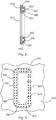
- FIG 3 shows a schematic plan view of a door opening in a wall of a tower segment of the wind turbine from FIG 1 .
- a reinforcing element or stiffening element 300 is provided around the door opening 210 (preferably on the inside of the wall 212) .
- the reinforcement element 300 has toothing elements 310 which are attached to the steel wall 212, in particular welded.
- the toothed elements 310 can be welded to the steel wall 212. Reinforcing bars 320 can then optionally be provided. Thereafter, a formwork 340 can be provided around the opening 210 and then a potting compound 330 can be filled into the formwork 340 . After the casting compound 330 has set or hardened, the formwork 340 can optionally be removed.
- the grout 330 may be in-situ concrete or a grout such as. B. represent Pagel.
- the reinforcing element can thus represent a reinforcing ring or a stiffening ring made of hardened casting compound, which is fastened to a steel wall via headed bolts (dowels) and is arranged around the opening.
Landscapes
- Engineering & Computer Science (AREA)
- Architecture (AREA)
- Chemical & Material Sciences (AREA)
- Life Sciences & Earth Sciences (AREA)
- Civil Engineering (AREA)
- Wood Science & Technology (AREA)
- Materials Engineering (AREA)
- Structural Engineering (AREA)
- Sustainable Development (AREA)
- Sustainable Energy (AREA)
- Combustion & Propulsion (AREA)
- Mechanical Engineering (AREA)
- General Engineering & Computer Science (AREA)
- Wind Motors (AREA)
Abstract
Description
- Die vorliegende Erfindung betrifft eine Windenergieanlage sowie ein Verfahren zum Herstellen eines Windenergieanlagen-Turms.
- Typischerweise weisen die Türme einer Windenergieanlage im unteren Turmsegment eine Türöffnung auf, damit Servicepersonal die Windenergieanlage betreten kann. Dazu muss eine Öffnung in der Wandung eines unteren Turmsegments vorhanden sein. Bei Turmsegmenten aus Stahl werden dazu Türzargen oder verstärkte Türbleche an- oder eingeschweißt. Dies ist erforderlich, weil jede Öffnung in einem Turmsegment zu einer mechanischen Schwächung des Turmsegmentes führt. Ein Auf- oder Anschweißen von Türzargen oder verstärkten Türblechen ist jedoch aufwändig und kostenintensiv.
- Es ist daher eine Aufgabe der vorliegenden Erfindung, eine Windenergieanlage sowie ein Verfahren zum Herstellen eines Turms einer Windenergieanlage vorzusehen, bei welchem Öffnungen in der Turmwandung vorgesehen werden können, welche eine Schwächung eines Turmsegmentes reduziert und kostengünstig ist.
- Diese Aufgabe wird durch eine Windenergieanlage nach Anspruch 1 sowie durch ein Verfahren zum Herstellen eines Windenergieanlagen-Turms nach Anspruch 4 gelöst.
- Somit wird eine Windenergieanlage mit einem Turm vorgesehen, der mindestens ein erstes und zweites Turmsegment aufweist. Das erste Turmsegment weist eine Stahlwandung und mindestens eine erste Öffnung in der Stahlwandung auf. Ferner ist mindestens ein Verstärkungselement mit einer ausgehärteten Vergussmasse um einen Bereich der ersten Öffnung herum vorgesehen.
- Damit kann eine Öffnung in einer Wandung eines Stahlturmsegmentes vorgesehen sein. Zur Verbesserung der Stabilität des Stahl-Turmsegmentes wird ein Verstärkungselement mit einer ausgehärteten Vergussmasse um die erste Öffnung herum vorgesehen. Somit kann erreicht werden, dass Türzargen oder Türbleche verbessert an die Stahlwandung angebracht werden können, um eine Verbesserung der Festigkeit des Turmsegmentes zu erreichen.
- Gemäß einem Aspekt der vorliegenden Erfindung weist das Verstärkungselement Verzahnungselemente auf, welche innen an der Wandung befestigt sind. Des Weiteren weist das Verstärkungselement die ausgehärtete Vergussmasse innen an der Wandung um die erste Öffnung herum auf. Die Verzahnungselemente ragen in die ausgehärtete Vergussmasse hinein.
- Gemäß einem weiteren Aspekt der vorliegenden Erfindung weist das Verstärkungselement Bewehrungsstäbe zur Verstärkung auf.
- Die Erfindung betrifft ebenfalls ein Verfahren zum Herstellen eines Windenergieanlagen-Turms. Ein Turmsegment mit einer Stahlwandung und einer ersten Öffnung wird ausgeformt. Verzahnungselemente werden an der Stahlwandung um die erste Öffnung herum befestigt. Eine Schale wird um die Öffnung herum vorgesehen. Die Verzahnungselemente ragen in ein Volumen hinein, das durch die Schalung umgeben ist. Vergussmasse wird in die Schalung eingefüllt und ausgehärtet.
- Weitere Ausgestaltungen der Erfindung sind Gegenstand der Unteransprüche.
- Vorteile und Ausführungsbeispiele der Erfindung werden nachstehend unter Bezugnahme auf die Zeichnung näher erläutert.
- Fig. 1
- zeigt eine Darstellung einer Windenergieanlage gemäß einem Ausführungsbeispiel der Erfindung,
- Fig. 2
- zeigt einen Ausschnitt einer Schnittansicht eines Turmsegmentes der Windenergieanlage von
Fig. 1 , und - Fig. 3
- zeigt eine schematische Draufsicht auf eine Türöffnung in einer Wandung eines Turmsegmentes der Windenergieanlage von
Fig. 1 . -
Fig. 1 zeigt eine Darstellung einer Windenergieanlage gemäß einem Ausführungsbeispiel der Erfindung. Die Windenergieanlage 100 weist einen Turm 200 auf, welcher aus mehreren Turmsegmenten 210 - 250 zusammengesetzt ist. Auf dem Turm 200 ist eine Gondel 104 sowie ein aerodynamischer Rotor 106 mit einem Spinner 110 und drei Rotorblättern 108 vorgesehen. Innerhalb der Gondel 104 ist ein elektrischer Generator vorgesehen, welcher direkt oder indirekt mit dem aerodynamischen Rotor 106 verbunden ist und elektrische Energie erzeugen kann. - Ein erstes Turmsegment oder eine erste Turmsektion 210 weist eine Stahlwandung und eine Öffnung 211 auf. Die anderen Turmsegmente 220 - 250 können optional ebenfalls Öffnungen aufweisen. Beispielsweise kann die Öffnung 211 eine Türöffnung in dem ersten Turmsegment 210 darstellen.
-
Fig. 2 zeigt einen Ausschnitt einer Schnittansicht eines Turmsegmentes der Windenergieanlage vonFig. 1 . Das untere Turmsegment 210 weist eine Stahlwandung 212 sowie eine Öffnung 211 in der Wandung 212 auf. Die Öffnung 211 kann beispielsweise eine Türöffnung darstellen. Zur Verbesserung der mechanischen Steifigkeit der Stahlwandung 212 im Bereich der Öffnung 211 wird ein Verstärkungselement 300 vorgesehen. An einer Innenseite der Stahlwandung 212 ist dazu eine Mehrzahl von Verzahnungselementen 310 um die Öffnung 211 herum vorgesehen. Die Verzahnungselemente 310 können beispielsweise Kopfbolzendübel darstellen, welche an der Innenseite der Wandung 212 befestigt (beispielsweise verschweißt) werden können. Optional können im Bereich der Verzahnungselemente 310 Bewehrungsstäbe 320 vorgesehen werden, bevor eine Vergussmasse 330 vorgesehen wird. Dies dient der verbesserten mechanischen Steifigkeit des Verstärkungselementes 300. - Das Verstärkungselement 300 weist somit die Verzahnungselemente 310, optional die Bewehrungsstäbe 320 und die Vergussmasse 330 auf.
-
Fig. 3 zeigt eine schematische Draufsicht auf eine Türöffnung in einer Wandung eines Turmsegmentes der Windenergieanlage vonFig. 1 . Um die Türöffnung 210 herum (vorzugsweise an der Innenseite der Wandung 212) ist ein Verstärkungselement oder Versteifungselement 300 vorgesehen. Das Verstärkungselement 300 weist Verzahnungselemente 310 auf, welche an der Stahlwandung 212 befestigt, insbesondere verschweißt sind. - Zur Herstellung des Verstärkungselementes 300 können die Verzahnungselemente 310 an die Stahlwandung 212 verschweißt werden. Anschließend können optional Bewehrungsstäbe 320 vorgesehen sein. Danach kann eine Schalung 340 um die Öffnung 210 herum vorgesehen sein und anschließend kann eine Vergussmasse 330 in die Schalung 340 eingefüllt werden. Nach Abbinden bzw. Aushärten der Vergussmasse 330 kann die Schalung 340 optional entfernt werden. Die Vergussmasse 330 kann Ortbeton oder ein Vergussmittel wie z. B. Pagel darstellen.
- Das Verstärkungselement kann somit einen Verstärkungsring oder einen Versteifungsring aus ausgehärteter Vergussmasse darstellen, die über Kopfbolzen(dübel) an einer Stahlwandung befestigt sind und um die Öffnung herum angeordnet sind.
-
- 100
- Windenergieanlage
- 104
- Gondel
- 106
- aerodynamischer Rotor
- 108
- Rotorblätter
- 200
- Turm
- 210
- erstes Turmsegment/Turmsektion
- 211
- (Tür)Öffnung
- 212
- Turmwandung
- 220
- zweites Turmsegment/Turmsektion
- 230
- drittes Turmsegment/Turmsektion
- 240
- viertes Turmsegment/Turmsektion
- 250
- fünftes Turmsegment/Turmsektion
- 300
- Verstärkungselement
- 310
- Verzahnungselemente
- 320
- Bewehrungsstäbe
- 330
- Vergussmasse
- 340
- Schalung
Claims (5)
- Windenergieanlage (100), miteinem Turm (200), der mindestens ein erstes und zweites Turmsegment (210, 220) aufweist,wobei das erste Turmsegment (210) eine Stahlwandung (212) und mindestens eine erste Öffnung (211) aufweist, undmindestens einem Verstärkungselement (300) mit einer ausgehärteten Vergussmasse (330) um einen Bereich der ersten Öffnung (211) herum.
- Windenergieanlage (100) nach Anspruch 1, wobeidas Verstärkungselement (300) Verzahnungselemente (310), welche innen an der Wandung (212) befestigt sind, und die ausgehärtete Vergussmasse (330) innen an der Wandung (212) um die erste Öffnung (211) herum aufweist,wobei die Verzahnungselemente (310) in die ausgehärtete Vergussmasse (330) hineinragen.
- Windenergieanlage (100) nach Anspruch 1 oder 2, wobei
das Verstärkungselement (300) Bewehrungsstäbe (320) zur Verstärkung des Verstärkungselementes (300) aufweist. - Windenergieanlagen-Turm (200), mitmindestens einem ersten und zweiten Turmsegment (210, 220),wobei das erste Turmsegment (210) eine Stahlwandung (212) und mindestens eine erste Öffnung (211) aufweist, undmindestens einem Verstärkungselement (300) mit einer ausgehärteten Vergussmasse (330) um einen Bereich der ersten Öffnung (211) herum.
- Verfahren zum Herstellen eines Windenergieanlagen-Turms, mit den Schritten:Formen eines Turmsegmentes (210) mit einer Stahlwandung (212) und einer ersten Öffnung (211),Befestigen von Verzahnungselementen (310) an der Stahlwandung (212) um die erste Öffnung (211) herum,Vorsehen einer Schalung (340) um die Öffnung (211) herum, wobei die Verzahnungselemente (310) in ein Volumen hineinragen, das durch die Schalung (340) umgeben ist,Einfüllen von Vergussmasse (330) in die Schalung (340), undAushärten der Vergussmasse (330).
Priority Applications (3)
| Application Number | Priority Date | Filing Date | Title |
|---|---|---|---|
| EP21183011.2A EP4112845B1 (de) | 2021-07-01 | 2021-07-01 | Windenergieanlage und verfahren zum herstellen eines windenergieanlagen-turms |
| US17/855,622 US20230003046A1 (en) | 2021-07-01 | 2022-06-30 | Wind turbine and method for manufacturing a wind turbine tower |
| CN202210760980.XA CN115559859A (zh) | 2021-07-01 | 2022-06-30 | 风能设施和用于制造风能设施塔的方法 |
Applications Claiming Priority (1)
| Application Number | Priority Date | Filing Date | Title |
|---|---|---|---|
| EP21183011.2A EP4112845B1 (de) | 2021-07-01 | 2021-07-01 | Windenergieanlage und verfahren zum herstellen eines windenergieanlagen-turms |
Publications (3)
| Publication Number | Publication Date |
|---|---|
| EP4112845A1 true EP4112845A1 (de) | 2023-01-04 |
| EP4112845C0 EP4112845C0 (de) | 2024-12-18 |
| EP4112845B1 EP4112845B1 (de) | 2024-12-18 |
Family
ID=76744626
Family Applications (1)
| Application Number | Title | Priority Date | Filing Date |
|---|---|---|---|
| EP21183011.2A Active EP4112845B1 (de) | 2021-07-01 | 2021-07-01 | Windenergieanlage und verfahren zum herstellen eines windenergieanlagen-turms |
Country Status (3)
| Country | Link |
|---|---|
| US (1) | US20230003046A1 (de) |
| EP (1) | EP4112845B1 (de) |
| CN (1) | CN115559859A (de) |
Citations (2)
| Publication number | Priority date | Publication date | Assignee | Title |
|---|---|---|---|---|
| EP0066340A1 (de) * | 1981-05-25 | 1982-12-08 | Alcoa Nederland B.V. | Lampenmast mit einer Verstärkung der unterhalb des Mastes befindlichen Öffnung |
| EP2253781A1 (de) * | 2009-05-21 | 2010-11-24 | Ecotecnia Energias Renovables, S.L. | Verbundstoffverbindung für eine Windturbinenturmstruktur |
Family Cites Families (1)
| Publication number | Priority date | Publication date | Assignee | Title |
|---|---|---|---|---|
| ES2525405T3 (es) * | 2011-01-24 | 2014-12-22 | Alstom Renewable Technologies | Procedimiento para montar elementos de torre para formar secciones de una torre híbrida de un aerogenerador |
-
2021
- 2021-07-01 EP EP21183011.2A patent/EP4112845B1/de active Active
-
2022
- 2022-06-30 US US17/855,622 patent/US20230003046A1/en not_active Abandoned
- 2022-06-30 CN CN202210760980.XA patent/CN115559859A/zh not_active Withdrawn
Patent Citations (2)
| Publication number | Priority date | Publication date | Assignee | Title |
|---|---|---|---|---|
| EP0066340A1 (de) * | 1981-05-25 | 1982-12-08 | Alcoa Nederland B.V. | Lampenmast mit einer Verstärkung der unterhalb des Mastes befindlichen Öffnung |
| EP2253781A1 (de) * | 2009-05-21 | 2010-11-24 | Ecotecnia Energias Renovables, S.L. | Verbundstoffverbindung für eine Windturbinenturmstruktur |
Also Published As
| Publication number | Publication date |
|---|---|
| CN115559859A (zh) | 2023-01-03 |
| US20230003046A1 (en) | 2023-01-05 |
| EP4112845C0 (de) | 2024-12-18 |
| EP4112845B1 (de) | 2024-12-18 |
Similar Documents
| Publication | Publication Date | Title |
|---|---|---|
| EP3821083B1 (de) | Fundament für ein windkraftwerk | |
| EP3516121B1 (de) | Fundament für eine windmühle | |
| EP3092357B1 (de) | Anordnung mit einem betonfundament und einem turm und verfahren zum errichten eines turms | |
| EP2776637B1 (de) | Fundament einer windenergieanlage | |
| EP3036378B1 (de) | Windenergieanlagen-fundament und windenergieanlage | |
| EP3924577B1 (de) | Hybrid-turmabschnitt, hybrid-turm für eine windenergieanlage sowie herstellungsverfahren | |
| EP2009202B1 (de) | Windenergieanlagenturm | |
| AT521433B1 (de) | Fundament für ein Windkraftwerk | |
| DE102008053454B4 (de) | Hybrides Turmbauwerk | |
| EP3701107B1 (de) | Ringförmige konsole zum externen spannen eines turmsegments, externes spannsystem eines hybridturms, turmabschnitt eines hybridturms, hybridturm, windenergieanlage und montageverfahren eines externen spannsystems für einen hybridturm | |
| EP3440351B1 (de) | Windenergieanlagen-turmringsegment, verfahren zum herstellen eines solchen und verfahren zum verbinden von zwei windenergieanlagen-turmringsegmenten | |
| EP3022026B1 (de) | Verfahren zum herstellen eines fertigbetonteil-segmentes eines windenergieanlagen-turmes und eine betonfertigteil-turmsegment-schalung | |
| EP3781811B1 (de) | Verfahren zum errichten eines windenergieanlagen-turms | |
| DE102016125062A1 (de) | Windenergieanlagen-Turm und Windenergieanlagen-Turmübergangssegment | |
| EP4112845B1 (de) | Windenergieanlage und verfahren zum herstellen eines windenergieanlagen-turms | |
| EP3845354B1 (de) | Verfahren zum herstellen von segmenten für einen turm, vorgespanntes segment, turmring, turm und windenergieanlage | |
| EP3163075B1 (de) | Windenergieanlage, lastenverteilungssystem einer windenergieanlage und verfahren zum errichten eines turms einer windenergieanlage | |
| EP3219879A1 (de) | Verfahren zum aufstellen eines windenergieanlagen-turms sowie entsprechende windenergieanlage | |
| EP3825550B1 (de) | Turmsegment und herstellungsverfahren | |
| EP3768898B1 (de) | Halbfertigteil für ein fundament eines turmbauwerks, halbfertigteil-fundamentsegment, fundament, verfahren zum herstellen eines halbfertigteils sowie verfahren zum herstellen eines fundaments | |
| EP3502378B1 (de) | Turmsegment für eine windenergieanlage und verfahren zum herstellen eines turmsegments | |
| EP4339457A1 (de) | Verfahren zur errichtung und/oder umrüstung einer windenergieanlage, verwendung eines turms einer windenergieanlage und windenergieanlage | |
| WO2016189083A1 (de) | Windenergieanlagen-turm | |
| EP4520497A1 (de) | Verfahren zur herstellung eines konischen oder zylindrischen ringsegments und eines spannbetonturms | |
| DE102016014847A1 (de) | Verfahren zum Aufstellen eines Windenergieanlagenturms aus Spannbeton sowie entsprechender Windenergieanlagenturm |
Legal Events
| Date | Code | Title | Description |
|---|---|---|---|
| PUAI | Public reference made under article 153(3) epc to a published international application that has entered the european phase |
Free format text: ORIGINAL CODE: 0009012 |
|
| STAA | Information on the status of an ep patent application or granted ep patent |
Free format text: STATUS: THE APPLICATION HAS BEEN PUBLISHED |
|
| AK | Designated contracting states |
Kind code of ref document: A1 Designated state(s): AL AT BE BG CH CY CZ DE DK EE ES FI FR GB GR HR HU IE IS IT LI LT LU LV MC MK MT NL NO PL PT RO RS SE SI SK SM TR |
|
| STAA | Information on the status of an ep patent application or granted ep patent |
Free format text: STATUS: REQUEST FOR EXAMINATION WAS MADE |
|
| 17P | Request for examination filed |
Effective date: 20230704 |
|
| RBV | Designated contracting states (corrected) |
Designated state(s): AL AT BE BG CH CY CZ DE DK EE ES FI FR GB GR HR HU IE IS IT LI LT LU LV MC MK MT NL NO PL PT RO RS SE SI SK SM TR |
|
| GRAP | Despatch of communication of intention to grant a patent |
Free format text: ORIGINAL CODE: EPIDOSNIGR1 |
|
| STAA | Information on the status of an ep patent application or granted ep patent |
Free format text: STATUS: GRANT OF PATENT IS INTENDED |
|
| GRAJ | Information related to disapproval of communication of intention to grant by the applicant or resumption of examination proceedings by the epo deleted |
Free format text: ORIGINAL CODE: EPIDOSDIGR1 |
|
| STAA | Information on the status of an ep patent application or granted ep patent |
Free format text: STATUS: REQUEST FOR EXAMINATION WAS MADE |
|
| GRAP | Despatch of communication of intention to grant a patent |
Free format text: ORIGINAL CODE: EPIDOSNIGR1 |
|
| STAA | Information on the status of an ep patent application or granted ep patent |
Free format text: STATUS: GRANT OF PATENT IS INTENDED |
|
| INTG | Intention to grant announced |
Effective date: 20240628 |
|
| INTC | Intention to grant announced (deleted) | ||
| INTG | Intention to grant announced |
Effective date: 20240718 |
|
| GRAS | Grant fee paid |
Free format text: ORIGINAL CODE: EPIDOSNIGR3 |
|
| GRAA | (expected) grant |
Free format text: ORIGINAL CODE: 0009210 |
|
| STAA | Information on the status of an ep patent application or granted ep patent |
Free format text: STATUS: THE PATENT HAS BEEN GRANTED |
|
| AK | Designated contracting states |
Kind code of ref document: B1 Designated state(s): AL AT BE BG CH CY CZ DE DK EE ES FI FR GB GR HR HU IE IS IT LI LT LU LV MC MK MT NL NO PL PT RO RS SE SI SK SM TR |
|
| REG | Reference to a national code |
Ref country code: CH Ref legal event code: EP |
|
| REG | Reference to a national code |
Ref country code: DE Ref legal event code: R096 Ref document number: 502021006132 Country of ref document: DE |
|
| REG | Reference to a national code |
Ref country code: IE Ref legal event code: FG4D Free format text: LANGUAGE OF EP DOCUMENT: GERMAN |
|
| U01 | Request for unitary effect filed |
Effective date: 20241218 |
|
| U07 | Unitary effect registered |
Designated state(s): AT BE BG DE DK EE FI FR IT LT LU LV MT NL PT RO SE SI Effective date: 20250102 |
|
| PG25 | Lapsed in a contracting state [announced via postgrant information from national office to epo] |
Ref country code: HR Free format text: LAPSE BECAUSE OF FAILURE TO SUBMIT A TRANSLATION OF THE DESCRIPTION OR TO PAY THE FEE WITHIN THE PRESCRIBED TIME-LIMIT Effective date: 20241218 |
|
| PG25 | Lapsed in a contracting state [announced via postgrant information from national office to epo] |
Ref country code: NO Free format text: LAPSE BECAUSE OF FAILURE TO SUBMIT A TRANSLATION OF THE DESCRIPTION OR TO PAY THE FEE WITHIN THE PRESCRIBED TIME-LIMIT Effective date: 20250318 |
|
| PG25 | Lapsed in a contracting state [announced via postgrant information from national office to epo] |
Ref country code: GR Free format text: LAPSE BECAUSE OF FAILURE TO SUBMIT A TRANSLATION OF THE DESCRIPTION OR TO PAY THE FEE WITHIN THE PRESCRIBED TIME-LIMIT Effective date: 20250319 |
|
| PG25 | Lapsed in a contracting state [announced via postgrant information from national office to epo] |
Ref country code: RS Free format text: LAPSE BECAUSE OF FAILURE TO SUBMIT A TRANSLATION OF THE DESCRIPTION OR TO PAY THE FEE WITHIN THE PRESCRIBED TIME-LIMIT Effective date: 20250318 |
|
| PG25 | Lapsed in a contracting state [announced via postgrant information from national office to epo] |
Ref country code: SM Free format text: LAPSE BECAUSE OF FAILURE TO SUBMIT A TRANSLATION OF THE DESCRIPTION OR TO PAY THE FEE WITHIN THE PRESCRIBED TIME-LIMIT Effective date: 20241218 |
|
| PG25 | Lapsed in a contracting state [announced via postgrant information from national office to epo] |
Ref country code: PL Free format text: LAPSE BECAUSE OF FAILURE TO SUBMIT A TRANSLATION OF THE DESCRIPTION OR TO PAY THE FEE WITHIN THE PRESCRIBED TIME-LIMIT Effective date: 20241218 |
|
| PG25 | Lapsed in a contracting state [announced via postgrant information from national office to epo] |
Ref country code: ES Free format text: LAPSE BECAUSE OF FAILURE TO SUBMIT A TRANSLATION OF THE DESCRIPTION OR TO PAY THE FEE WITHIN THE PRESCRIBED TIME-LIMIT Effective date: 20241218 |
|
| PG25 | Lapsed in a contracting state [announced via postgrant information from national office to epo] |
Ref country code: IS Free format text: LAPSE BECAUSE OF FAILURE TO SUBMIT A TRANSLATION OF THE DESCRIPTION OR TO PAY THE FEE WITHIN THE PRESCRIBED TIME-LIMIT Effective date: 20250418 |
|
| PG25 | Lapsed in a contracting state [announced via postgrant information from national office to epo] |
Ref country code: SK Free format text: LAPSE BECAUSE OF FAILURE TO SUBMIT A TRANSLATION OF THE DESCRIPTION OR TO PAY THE FEE WITHIN THE PRESCRIBED TIME-LIMIT Effective date: 20241218 |
|
| PG25 | Lapsed in a contracting state [announced via postgrant information from national office to epo] |
Ref country code: CZ Free format text: LAPSE BECAUSE OF FAILURE TO SUBMIT A TRANSLATION OF THE DESCRIPTION OR TO PAY THE FEE WITHIN THE PRESCRIBED TIME-LIMIT Effective date: 20241218 |
|
| U20 | Renewal fee for the european patent with unitary effect paid |
Year of fee payment: 5 Effective date: 20250630 |
|
| PLBE | No opposition filed within time limit |
Free format text: ORIGINAL CODE: 0009261 |
|
| STAA | Information on the status of an ep patent application or granted ep patent |
Free format text: STATUS: NO OPPOSITION FILED WITHIN TIME LIMIT |
|
| REG | Reference to a national code |
Ref country code: CH Ref legal event code: L10 Free format text: ST27 STATUS EVENT CODE: U-0-0-L10-L00 (AS PROVIDED BY THE NATIONAL OFFICE) Effective date: 20251029 |
|
| 26N | No opposition filed |
Effective date: 20250919 |
|
| REG | Reference to a national code |
Ref country code: CH Ref legal event code: H13 Free format text: ST27 STATUS EVENT CODE: U-0-0-H10-H13 (AS PROVIDED BY THE NATIONAL OFFICE) Effective date: 20260224 |
|
| GBPC | Gb: european patent ceased through non-payment of renewal fee |
Effective date: 20250701 |
|
| PG25 | Lapsed in a contracting state [announced via postgrant information from national office to epo] |
Ref country code: GB Free format text: LAPSE BECAUSE OF NON-PAYMENT OF DUE FEES Effective date: 20250701 |
|
| PG25 | Lapsed in a contracting state [announced via postgrant information from national office to epo] |
Ref country code: CH Free format text: LAPSE BECAUSE OF NON-PAYMENT OF DUE FEES Effective date: 20250731 |