EP4112809A1 - Fiber body manufacturing apparatus, fiber body manufacturing unit, and fiber body manufacturing method - Google Patents
Fiber body manufacturing apparatus, fiber body manufacturing unit, and fiber body manufacturing method Download PDFInfo
- Publication number
- EP4112809A1 EP4112809A1 EP22181197.9A EP22181197A EP4112809A1 EP 4112809 A1 EP4112809 A1 EP 4112809A1 EP 22181197 A EP22181197 A EP 22181197A EP 4112809 A1 EP4112809 A1 EP 4112809A1
- Authority
- EP
- European Patent Office
- Prior art keywords
- web
- section
- water
- transport
- fiber body
- Prior art date
- Legal status (The legal status is an assumption and is not a legal conclusion. Google has not performed a legal analysis and makes no representation as to the accuracy of the status listed.)
- Pending
Links
Images


Classifications
-
- D—TEXTILES; PAPER
- D04—BRAIDING; LACE-MAKING; KNITTING; TRIMMINGS; NON-WOVEN FABRICS
- D04H—MAKING TEXTILE FABRICS, e.g. FROM FIBRES OR FILAMENTARY MATERIAL; FABRICS MADE BY SUCH PROCESSES OR APPARATUS, e.g. FELTS, NON-WOVEN FABRICS; COTTON-WOOL; WADDING ; NON-WOVEN FABRICS FROM STAPLE FIBRES, FILAMENTS OR YARNS, BONDED WITH AT LEAST ONE WEB-LIKE MATERIAL DURING THEIR CONSOLIDATION
- D04H1/00—Non-woven fabrics formed wholly or mainly of staple fibres or like relatively short fibres
- D04H1/40—Non-woven fabrics formed wholly or mainly of staple fibres or like relatively short fibres from fleeces or layers composed of fibres without existing or potential cohesive properties
- D04H1/58—Non-woven fabrics formed wholly or mainly of staple fibres or like relatively short fibres from fleeces or layers composed of fibres without existing or potential cohesive properties by applying, incorporating or activating chemical or thermoplastic bonding agents, e.g. adhesives
-
- D—TEXTILES; PAPER
- D21—PAPER-MAKING; PRODUCTION OF CELLULOSE
- D21F—PAPER-MAKING MACHINES; METHODS OF PRODUCING PAPER THEREON
- D21F9/00—Complete machines for making continuous webs of paper
-
- D—TEXTILES; PAPER
- D21—PAPER-MAKING; PRODUCTION OF CELLULOSE
- D21F—PAPER-MAKING MACHINES; METHODS OF PRODUCING PAPER THEREON
- D21F7/00—Other details of machines for making continuous webs of paper
- D21F7/003—Indicating or regulating the moisture content of the layer
-
- D—TEXTILES; PAPER
- D04—BRAIDING; LACE-MAKING; KNITTING; TRIMMINGS; NON-WOVEN FABRICS
- D04H—MAKING TEXTILE FABRICS, e.g. FROM FIBRES OR FILAMENTARY MATERIAL; FABRICS MADE BY SUCH PROCESSES OR APPARATUS, e.g. FELTS, NON-WOVEN FABRICS; COTTON-WOOL; WADDING ; NON-WOVEN FABRICS FROM STAPLE FIBRES, FILAMENTS OR YARNS, BONDED WITH AT LEAST ONE WEB-LIKE MATERIAL DURING THEIR CONSOLIDATION
- D04H1/00—Non-woven fabrics formed wholly or mainly of staple fibres or like relatively short fibres
- D04H1/70—Non-woven fabrics formed wholly or mainly of staple fibres or like relatively short fibres characterised by the method of forming fleeces or layers, e.g. reorientation of fibres
- D04H1/72—Non-woven fabrics formed wholly or mainly of staple fibres or like relatively short fibres characterised by the method of forming fleeces or layers, e.g. reorientation of fibres the fibres being randomly arranged
-
- D—TEXTILES; PAPER
- D06—TREATMENT OF TEXTILES OR THE LIKE; LAUNDERING; FLEXIBLE MATERIALS NOT OTHERWISE PROVIDED FOR
- D06B—TREATING TEXTILE MATERIALS USING LIQUIDS, GASES OR VAPOURS
- D06B1/00—Applying liquids, gases or vapours onto textile materials to effect treatment, e.g. washing, dyeing, bleaching, sizing or impregnating
- D06B1/02—Applying liquids, gases or vapours onto textile materials to effect treatment, e.g. washing, dyeing, bleaching, sizing or impregnating by spraying or projecting
-
- D—TEXTILES; PAPER
- D21—PAPER-MAKING; PRODUCTION OF CELLULOSE
- D21F—PAPER-MAKING MACHINES; METHODS OF PRODUCING PAPER THEREON
- D21F11/00—Processes for making continuous lengths of paper, or of cardboard, or of wet web for fibre board production, on paper-making machines
- D21F11/06—Processes for making continuous lengths of paper, or of cardboard, or of wet web for fibre board production, on paper-making machines of the cylinder type
-
- D—TEXTILES; PAPER
- D21—PAPER-MAKING; PRODUCTION OF CELLULOSE
- D21F—PAPER-MAKING MACHINES; METHODS OF PRODUCING PAPER THEREON
- D21F3/00—Press section of machines for making continuous webs of paper
- D21F3/02—Wet presses
- D21F3/0272—Wet presses in combination with suction or blowing devices
-
- D—TEXTILES; PAPER
- D21—PAPER-MAKING; PRODUCTION OF CELLULOSE
- D21F—PAPER-MAKING MACHINES; METHODS OF PRODUCING PAPER THEREON
- D21F9/00—Complete machines for making continuous webs of paper
- D21F9/04—Complete machines for making continuous webs of paper of the cylinder type
- D21F9/046—Complete machines for making continuous webs of paper of the cylinder type with non-immersed cylinder
Definitions
- the present disclosure relates to a fiber body manufacturing apparatus, a fiber body manufacturing unit, and a fiber body manufacturing method.
- a sheet manufacturing apparatus including an accumulating section that forms a web by accumulating a material containing fibers on a mesh belt; a humidifying section arranged downstream of the accumulating section in a web transport direction to humidify the web; a transport section arranged downstream of the humidifying section in the web transport direction to transport the web downstream while peeling off the web from the mesh belt; and a pressure roller arranged downstream of the transport section in the web transport direction to pressurize the web, is known.
- the humidifying section performs humidification toward one surface of the web, and the transport section comes into contact with the one surface of the web to perform transport.
- the transport section comes into contact with one surface having a larger amount of water, there is a problem that the web sticks to the transport section.
- the web When the web sticks to the transport section, the web may be poorly transported or the web may be damaged.
- a fiber body manufacturing apparatus including: an accumulating section that forms a web by accumulating a material containing fibers on a first transport belt by a dry method; a transport section that transports the web by peeling off a first surface of the web from the first transport belt, and by bringing a second surface of the web, which is a surface opposite to the first surface peeled off from the first transport belt, into contact with a second transport belt; a water-applying section that applies water toward the first surface of the web in a state where the web is in contact with the second transport belt; and a pressurizing section that pressurizes the web to which the water is applied and which is peeled off from the second transport belt.
- a fiber body manufacturing unit including: an accumulating section that forms a web by accumulating a material containing fibers on a first transport belt by a dry method; a transport section that transports the web by peeling off a first surface of the web from the first transport belt, and by bringing a second surface of the web, which is a surface opposite to the first surface peeled off from the first transport belt, into contact with a second transport belt; and a water-applying section that applies water toward the first surface of the web which is in contact with the second transport belt.
- a fiber body manufacturing method in a fiber body manufacturing apparatus including an accumulating section having a first transport belt configured to transport a web, a transport section having a second transport belt configured to transport the web, a water-applying section that applies water to the web, and a pressurizing section that pressurizes the web, the method including: an accumulating step of forming the web by accumulating a material containing fibers on the first transport belt by a dry method; a transport step of transporting the web by peeling off a first surface of the web from the first transport belt, and by bringing a second surface of the web, which is a surface opposite to the first surface peeled off from the first transport belt, into contact with the second transport belt; a water-applying step of applying the water toward the first surface of the web which is in contact with the second transport belt; and a pressurizing step of pressurizing the web to which the water is applied and which is peeled off from the second transport belt.
- the fiber body manufacturing apparatus 100 is an apparatus for manufacturing a sheet-like fiber body S.
- the fiber body manufacturing apparatus 100 includes, for example, a supply section 10, a crushing section 12, a defibration section 20, a sorting section 40, a first web forming section 45, a rotating body 49, a mixing section 50, an accumulating section 60, a second web forming section 70, a transport section 78, a water-applying section 79, a pressurizing section 80, and a cutting section 90.
- the supply section 10 supplies the raw material to the crushing section 12.
- the supply section 10 is, for example, an automatic charging section for continuously charging the raw material into the crushing section 12.
- the raw material supplied by the supply section 10 is a material containing various fibers.
- the fiber is not particularly limited, and a wide range of fiber materials can be used.
- the fiber include natural fiber (animal fiber, plant fiber) and chemical fiber (organic fiber, inorganic fiber, organic-inorganic composite fiber). More specifically, the fiber includes fibers made of cellulose, silk, wool, cotton, cannabis, kenaf, flax, ramie, jute, Manila hemp, sisal, coniferous tree, broadleaf tree, and the like, and these may be used alone, may be appropriately mixed and used, or may be used as a purified regenerated fiber.
- the raw material of the fiber examples include pulp, used paper, and used cloth. Further, the fiber may be subjected to various surface treatments. Further, the material of the fiber may be a pure substance or a material containing a plurality of components such as impurities and other components. Further, as the fiber, a defibrated product obtained by defibrating used paper, pulp sheet, or the like by a dry method may be used.
- the length of the fiber is not particularly limited, but in a case of one independent fiber, the length along the longitudinal direction of the fiber is 1 ⁇ m or more and 5 mm or less, preferably 2 ⁇ m or more and 3 mm or less, and more preferably 3 ⁇ m or more and 2 mm or less.
- the mechanical strength of a formed fiber body S can be increased by using a fiber having the ability to form hydrogen bonds.
- fibers include cellulose.
- the fiber content in the fiber body S is, for example, 50% by mass or more and 99.9% by mass or less, preferably 60% by mass or more and 99% by mass or less, and more preferably 70% by mass or more and 99% by mass or less. Such a content can be obtained by performing mixing when forming the mixture.
- the crushing section 12 cuts the raw material supplied by the supply section 10 into strips in the air such as the atmosphere.
- the shape and size of the strips are, for example, several centimeter square.
- the crushing section 12 has a crushing blade 14, and the charged raw material can be cut by the crushing blade 14.
- a shredder is used as the crushing section 12.
- the raw material cut by the crushing section 12 is received by a hopper 1 and then transferred to the defibration section 20 through a pipe 2.
- the defibration section 20 defibrates the raw material cut by the crushing section 12.
- “defibrating” means unraveling a raw material obtained by binding a plurality of fibers into each fiber.
- the defibration section 20 also has a function of separating substances such as resin particles, ink, toner, and a blot inhibitor adhering to the raw material from the fibers.
- a product that passed through the defibration section 20 is referred to as "defibrated product".
- the “defibrated product” may include resin particles separated from the fiber when the fiber is unraveled, coloring agents such as ink and toner, or additives such as blot inhibitors and paper strength enhancers.
- the shape of the unraveled defibrated product is a shape of a string.
- the unraveled defibrated product may exist in a state of not being entangled with other unraveled fibers, that is, in an independent state, or may exist in a state of being entangled with other unraveled defibrated products to form a mass shape, that is, in a state where a lump is formed.
- the defibration section 20 performs defibration by a dry method.
- the treatment of defibrating or the like in the air such as the atmosphere, not in the liquid is referred to as a dry method.
- an impeller mill is used as the defibration section 20 .
- the defibration section 20 has a function of suctioning the raw material and generating an airflow that discharges the defibrated product. Accordingly, the defibration section 20 can suction the raw material together with the airflow from an introduction port 22 by the airflow generated by itself, perform the defibration treatment, and transport the defibrated product to a discharge port 24.
- the defibrated product that passed through the defibration section 20 is transferred to the sorting section 40 through the pipe 3.
- the airflow generated by the defibration section 20 may be used, or an airflow generating apparatus such as a blower may be provided to use this airflow.
- the sorting section 40 introduces the defibrated product defibrated by the defibration section 20 from the introduction port 42 and sorts the defibrated product according to the length of the fibers.
- the sorting section 40 has, for example, a drum section 41 and a housing section 43 that accommodates the drum section 41 therein.
- As the drum section 41 for example, a sieve is used.
- the drum section 41 has a net, and can sort out fibers or particles smaller than the size of the mesh opening of the net, that is, a first sorted product passing through the net, and fibers, undefibrated pieces, and lumps larger than the size of the mesh opening of the net, that is, a second sorted product that does not pass through the net.
- the first sorted product is transferred to the accumulating section 60 through a pipe 7.
- the second sorted product is returned from the discharge port 44 to the defibration section 20 through a pipe 8.
- the drum section 41 is a cylindrical sieve that is rotationally driven by a motor.
- a wire net an expanded metal obtained by stretching a metal plate having a cut, or a punching metal in which a hole is formed in the metal plate by a press machine or the like is used.
- the first web forming section 45 transports the first sorted product that passed through the sorting section 40 to the pipe 7.
- the first web forming section 45 includes, for example, a mesh belt 46, a stretching roller 47, and a suction mechanism 48.
- the suction mechanism 48 can suction the first sorted product dispersed in the air through the opening of the sorting section 40 onto the mesh belt 46.
- the first sorted product is accumulated on the moving mesh belt 46 to form a web V.
- Passing products that passed through the opening of the sorting section 40 are accumulated on the mesh belt 46.
- the mesh belt 46 is stretched by the stretching roller 47, and is configured such that the passing products are unlikely to pass therethrough and air is allowed to pass therethrough.
- the mesh belt 46 moves as the stretching roller 47 revolves. While the mesh belt 46 moves continuously, the passing products that passed through the sorting section 40 are continuously piled up, and accordingly, the web V is formed on the mesh belt 46.
- the suction mechanism 48 is provided below the mesh belt 46.
- the suction mechanism 48 can generate a downward airflow.
- the suction mechanism 48 the passing products dispersed in the air by the sorting section 40 can be suctioned onto the mesh belt 46. Accordingly, the discharge speed from the sorting section 40 can be increased.
- the web V is formed in a soft and swollen state containing a large amount of air by passing through the sorting section 40 and the first web forming section 45.
- the web V accumulated on the mesh belt 46 is charged into the pipe 7 and transported to the accumulating section 60.
- the rotating body 49 can cut the web V.
- the rotating body 49 has a base portion 49a and a protrusion portion 49b protruding from the base portion 49a.
- the protrusion portion 49b has, for example, a plate-like shape.
- four protrusion portions 49b are provided, and four protrusion portions 49b are provided at equal intervals.
- the protrusion portion 49b can rotate around the base portion 49a as an axis.
- the rotating body 49 is provided in the vicinity of the first web forming section 45.
- the rotating body 49 is provided in the vicinity of the stretching roller 47a positioned downstream in the path of the web V.
- the rotating body 49 is provided at a position where the protrusion portion 49b can come into contact with the web V and does not come into contact with the mesh belt 46 on which the web V is accumulated. Accordingly, it is possible to suppress abrasion of the mesh belt 46 by the protrusion portion 49b.
- the shortest distance between the protrusion portion 49b and the mesh belt 46 is, for example, 0.05 mm or more and 0.5 mm or less. This is the distance at which the mesh belt 46 can cut the web V without being damaged.
- the mixing section 50 mixes, for example, the first sorted product that passed through the sorting section 40 and the binder.
- the mixing section 50 has, for example, a binder supply section 52 that supplies the binder, a pipe 54 for transporting the first sorted product and the binder, and a blower 56.
- the binder is supplied from the binder supply section 52 to the pipe 54 through the hopper 9.
- the pipe 54 is continuous with the pipe 7.
- an airflow is generated by the blower 56, and the first sorted product and the binder can be transported while being mixed in the pipe 54.
- the mechanism for mixing the first sorted product and the binder is not particularly limited, and may be agitated by a blade that rotates at high speed, or may use rotation of a container such as a V-type mixer.
- a screw feeder, a disc feeder, or the like is used as the binder supply section 52 .
- the binder supplied from the binder supply section 52 is, for example, starch or dextrin.
- Starch is a polymer in which a plurality of ⁇ -glucose molecules are polymerized by glycosidic bonds.
- the starch may be linear or may contain branches.
- starch those derived from various plants can be used.
- Raw materials for starch include grains such as corn, wheat, and rice, beans such as broad beans, mung beans, and red beans, tubers such as potatoes, sweet potatoes, and tapioca, wild grasses such as Erythronium japonicum, bracken, and kudzu, and palms such as sago palm.
- processed starch or modified starch may be used as the starch.
- the processed starch include acetylated adipic acid cross-linked starch, acetylated starch, oxidized starch, octenyl succinate starch sodium, hydroxypropyl starch, hydroxypropylated phosphoric acid cross-linked starch, phosphorylated starch, phosphoric acid esterified phosphoric acid cross-linked starch, urea phosphorylated esterified starch, sodium starch glycolate, and high amylose corn starch.
- the dextrin that serves as the modified starch those obtained by processing or modifying the starch can be preferably used.
- the fiber body manufacturing apparatus 100 by using starch or dextrin as a binder, at least one of gelatinization of the binder and hydrogen bonds between the fibers occurs by being pressurized and heated after water is applied, and the fiber body S can be given sufficient strength. Meanwhile, when the fiber body S can be given sufficient strength only by hydrogen bonds between the fibers, the fiber body can be manufactured without using a binder. When the fiber body is manufactured without using the binder, the fiber body manufacturing apparatus 100 may not include the binder supply section 52.
- the content of starch or dextrin in the fiber body S is, for example, 0.1% by mass or more and 50% by mass or less, preferably 1% by mass or more and 40% by mass or less, and more preferably 1% by mass or more and 30% by mass or less. Such a content can be obtained by performing mixing when forming the mixture.
- a colorant for coloring the fibers in addition to the binder, in accordance with the type of the fiber body S to be manufactured, a colorant for coloring the fibers, a coagulation inhibitor for suppressing coagulation of fibers or coagulation of binder, a flame retardant for making fibers and the like unlikely to burn, and the like, may be included.
- the mixture that passed through the mixing section 50 is transferred to the accumulating section 60 through the pipe 54.
- the accumulating section 60 introduces the mixture that passed through the mixing section 50 from an introduction port 62, unravels the entangled defibrated product, and disperses the unraveled defibrated product in the air to make the product fall. Accordingly, the accumulating section 60 can uniformly accumulate the mixture on the second web forming section 70.
- the accumulating section 60 has, for example, a drum section 61 and a housing section 63 that accommodates the drum section 61 therein.
- a rotating cylindrical sieve is used as the drum section 61.
- the drum section 61 has a net and makes fibers or particles smaller than the size of the mesh opening of the net, which are contained in the mixture that passed through the mixing section 50, fall.
- the configuration of the drum section 61 is, for example, the same as the configuration of the drum section 41.
- the "sieve” of the drum section 61 may not have a function of sorting a specific object.
- the "sieve” used as the drum section 61 means a sieve provided with a net, and the drum section 61 may make all of the mixture introduced into the drum section 61 fall.
- the second web forming section 70 accumulates the passing products that passed through the accumulating section 60 to form the web W.
- the second web forming section 70 includes, for example, a first mesh belt 72 that serves as a first transport belt, a stretching roller 74, and a suction mechanism 76.
- Passing products that passed through the opening of the accumulating section 60 are accumulated on the first mesh belt 72.
- the first mesh belt 72 is stretched by the stretching roller 74, and is configured such that the passing products are unlikely to pass therethrough and air is allowed to pass therethrough.
- the first mesh belt 72 moves as the stretching roller 74 revolves. While the first mesh belt 72 moves continuously, the passing products that passed through the accumulating section 60 are continuously piled up, and accordingly, the web W is formed on the first mesh belt 72.
- the suction mechanism 76 is provided below the first mesh belt 72.
- the suction mechanism 76 can generate a downward airflow.
- the suction mechanism 76 the mixture dispersed in the air by the accumulating section 60 can be suctioned onto the first mesh belt 72. Accordingly, the discharge speed from the accumulating section 60 can be increased.
- the suction mechanism 76 can form a downflow in the falling path of the mixture, and can prevent the defibrated product and the binder from being entangled during the fall.
- the web W in a soft and swollen state containing a large amount of air is formed by passing through the accumulating section 60 and the second web forming section 70.
- the transport section 78 is arranged downstream of the first mesh belt 72 in the transport direction of the web W.
- the transport section 78 peels off the web W on the first mesh belt 72 from the first mesh belt 72 and transports the web W toward the pressurizing section 80.
- the transport section 78 has a second mesh belt 78a that serves as a second transport belt, a roller 78b, and a suction mechanism 78c.
- the second mesh belt 78a is stretched by the roller 78b, and is configured such that the air is allowed to pass therethrough.
- the second mesh belt 78a is configured to be movable by the revolution of the roller 78b.
- the suction mechanism 78c is arranged at a position facing the web W with the second mesh belt 78a interposed therebetween.
- the suction mechanism 78c includes a blower, and generates an upward airflow in the second mesh belt 78a by the suction force of the blower.
- the web W is suctioned by this airflow.
- a first surface Wa of the web W is peeled off from the first mesh belt 72, and a second surface Wb which is a surface opposite to the first surface Wa peeled off from the first mesh belt 72 can be adsorbed to the second mesh belt 78a.
- the web W adsorbed to the second mesh belt 78a is transported in a state of being in contact with the second mesh belt 78a.
- the water-applying section 79 is arranged below the transport section 78.
- the water-applying section 79 applies water toward the first surface Wa of the web W which is in contact with the second mesh belt 78a.
- the water for example, water vapor or mist is applied to the web W. Accordingly, water can be uniformly applied to the web W.
- the water-applying section 79 applies water from below the web W toward the first surface Wa.
- a container 79a capable of storing water and a piezoelectric vibrator 79b arranged at the bottom portion of the container 79a are provided.
- the upper portion of the container 79a is opened, and the container 79a is arranged such that the opening faces the first surface Wa side of the web W.
- By driving the piezoelectric vibrator 79b ultrasonic waves are generated in the water and mist is generated in the container 79a.
- the generated mist is supplied to the web W through the opening of the container 79a.
- the suction mechanism 78c of the transport section 78 is arranged at a position facing the water-applying section 79 with the second mesh belt 78a interposed therebetween. Accordingly, the airflow containing water generated in the water-applying section 79 by the suction mechanism 78c can pass through the inside of the web W and apply water to the inside of the web W.
- the suction mechanism 78c is arranged so as to face a part of the first mesh belt 72 of the second web forming section 70 and the container 79a of the water-applying section 79.
- the common suction mechanism 78c has a function of peeling off the web W from the first mesh belt 72 and adsorbing the web W to the second mesh belt 78a and a function of applying water to the inside of the web W. Therefore, the configuration of the fiber body manufacturing apparatus 100 can be simplified.
- water is applied from the first surface Wa side opposite to the second surface Wb of the web W which is in contact with the second mesh belt 78a, and thus the second surface Wb side can be transported with a weaker adhesive force than the first surface Wa side. Therefore, it is possible to suppress the sticking of the web W, to which the water is applied, to the second mesh belt 78a.
- the water content of the web W to which water was applied in the water-applying section 79 is preferably 12% by mass or more and 40% by mass or less. With the specified web water content, hydrogen bonds between fibers can be effectively formed and the strength of the fiber body S can be increased.
- the web W having a water content of 12% by mass or more is generally in a state of being easily attached to the transport section.
- water is applied to the web W from the first surface Wa side opposite to the second surface Wb of the web W which is in contact with the second mesh belt 78a, and accordingly, even on the web W which is easily attached to the transport section, the sticking to the second mesh belt 78a can be suppressed. Further, by specifying the water content of the web W to be 40% by mass or less, the amount of water used can be reduced.
- the web W containing a binder (starch or dextrin) is generally in a state of being easily attached to the transport section, but in the present embodiment, even in a case of such a web W, the sticking to the second mesh belt 78a is suppressed, the binding force between the fibers is increased by the binder, and the strength of the fiber body S can be increased.
- a binder starch or dextrin
- the pressurizing section 80 is arranged downstream of the transport section 78 and the water-applying section 79.
- the web W to which the water is applied is transported to the pressurizing section 80.
- the pressurizing section 80 pressurizes the web W to which the water is applied and which is peeled off from the second mesh belt 78a.
- the pressurizing section 80 of the present embodiment simultaneously pressurizes and heats the web W to which water is applied. Accordingly, the water contained in the web W evaporates after the temperature rises, and the thickness of the web W becomes thin to increase the fiber density.
- the temperature of the water and the binder rises due to heat, the fiber density increases due to the pressure, and accordingly, the binder is gelatinized, and then the water evaporates to bind the plurality of fibers to each other through the gelatinized binder.
- the pressurizing section 80 of the present embodiment has a pressurizing heating section 84 that pressurizes and heats the web W.
- the pressurizing heating section 84 can be configured by using, for example, a heating roller or a heat press molding machine.
- the pressurizing heating section 84 is a pair of heating rollers 86.
- the number of heating rollers 86 is not particularly limited.
- the pressurizing heating section 84 can simultaneously pressurize and heat the web W. Further, the configuration of the fiber body manufacturing apparatus 100 can be simplified.
- the cutting section 90 cuts the fiber body S molded by the pressurizing section 80.
- the cutting section 90 includes a first cutting section 92 that cuts the fiber body S in a direction intersecting the transport direction of the fiber body S, and a second cutting section 94 that cuts the fiber body S in a direction parallel to the transport direction.
- the second cutting section 94 cuts, for example, the fiber body S that passed through the first cutting section 92.
- a single-cut fiber body S having a predetermined size is molded.
- the cut single-cut fiber body S is discharged to a discharge receiving section 96.
- a material containing fibers is accumulated on the first mesh belt 72 by a dry method to form the web W.
- a mixture containing defibrated fibers and a binder is accumulated by a dry method to form the web W.
- the fiber is a defibrated product defibrated by the defibration section 20
- the binder is supplied from the binder supply section 52
- the mixture is formed by the mixing section 50.
- the accumulating section 60 and the second web forming section 70 accumulate the mixture by a dry method to form the web W.
- the first surface Wa of the web W is peeled off from the first mesh belt 72, and the second surface Wb, which is a surface opposite to the first surface Wa peeled off from the first mesh belt 72, is brought into contact with the second mesh belt 78a to transport the web W.
- the suction mechanism 78c of the transport section 78 generates an upward airflow in the second mesh belt 78a to suction the web W. Accordingly, the first surface Wa of the web W is peeled off from the first mesh belt 72, and the web W is transported in a state where the second surface Wb is in contact with the second mesh belt 78a.
- step S13 water is applied toward the first surface Wa of the web W which is in contact with the second mesh belt 78a.
- water is applied to the web W during the period in which the web W is being transported in the transport step.
- water is supplied from the water-applying section 79.
- water vapor or mist is applied to the web W.
- the amount of water applied in the water-applying step can be managed by, for example, the water content of the web W.
- the water content of the web W to which water was applied in the water-applying step is preferably 12% by mass or more and 40% by mass or less. When the amount of water applied is approximately this level, it is possible to manufacture the fiber body S having higher strength while suppressing the amount of energy such as electric power required for heating and drying the web W.
- the second surface Wb side has a weaker adhesive force than the first surface Wa side, and thus it is possible to suppress the sticking of the web W, to which the water is applied, to the second mesh belt 78a.
- step S14 water is applied, and the web W peeled off from the second mesh belt 78a is pressurized.
- a pair of heating rollers 86 of the pressurizing section 80 applies pressure to the web W to thin the web and increase the fiber density in the web W.
- the pressure applied to the web W is preferably 0.1 MPa or more and 15 MPa or less, more preferably 0.2 MPa or more and 10 MPa or less, and further preferably 0.4 MPa or more and 8 MPa or less.
- the pressure applied to the web W in the pressurizing step is within such a range, the deterioration of the fiber can be suppressed, and the fiber body S having good strength can be manufactured again using the defibrated product obtained by defibrating the manufactured fiber body S as a raw material.
- the pressurizing step heat is applied to the web W to evaporate the water contained in the web W.
- the web W is heated so as to have a temperature of 60°C or higher and 100°C or lower. By doing so, the time required for the pressurizing step can be reduced, and the fiber body S can be manufactured with lower energy.
- the pressurizing step since a relatively low pressure is applied to the web W, a small manufacturing apparatus can be used, and since the damage to the fiber is relatively small, the fiber body S is defibrated again to make it easy to manufacture a new fiber body S.
- the web W is heated to a relatively low temperature, it is easy to form hydrogen bonds between the fibers and it is easy to secure the strength of the fiber body S. Further, since the binder can be gelatinized, the fibers can be bound to each other by the binder, and the strength of the fiber body S can be obtained.
- the fiber body manufacturing unit 1000 includes the accumulating section 60 that forms the web W by accumulating a material containing fibers on the first mesh belt 72 that serves as a first transport belt; the transport section 78 that transports the web by peeling off the first surface Wa of the web W from the first mesh belt 72, and by bringing the second surface Wb, which is a surface opposite to the first surface Wa peeled off from the first mesh belt 72, into contact with the second mesh belt 78a that serves as a second transport belt; and the water-applying section 79 that applies water toward the first surface Wa of the web W which is in contact with the second mesh belt 78a.
- the fiber body manufacturing unit 1000 can suppress the sticking of the web W, to which the water is applied, to the second transport belt, as in the above-described embodiment.
- the fiber body manufacturing unit 1000 includes, for example, the supply section 10, the crushing section 12, the defibration section 20, the sorting section 40, the first web forming section 45, the rotating body 49, the mixing section 50, and the like.
- the configuration in which the web W is brought into contact with the second mesh belt 78a and transported by the suction mechanism 78c of the transport section 78 was described, but the configuration is not limited thereto, and the configuration that does not include the suction mechanism 78c may also be adopted.
- a fiber body manufacturing apparatus 100A of the present embodiment includes the accumulating section 60, the second web forming section 70, a transport section 102, the water-applying section 79, and the pressurizing section 80.
- the web W formed on the first mesh belt 72 as the first transport belt is transported by the rotational movement of the first mesh belt 72. Then, the web W transported to the downstream end portion (a part corresponding to a stretching roller 74b) of the first mesh belt 72 is transported downward while being stuck to the first mesh belt 72.
- the angle formed by a first belt surface F1 on the first mesh belt 72 and a third belt surface F3 of the first mesh belt 72 stretched between the stretching roller 74b and the stretching roller 74c is less than 90 degrees. Therefore, the web W is peeled off from the third belt surface F3 by its own weight. As a result, the web W is delivered from the first mesh belt 72 to the transport section 102 and transported.
- the transport section 102 is arranged below the first belt surface F1 on the first mesh belt 72.
- a second mesh belt 105 that serves as a second transport belt stretched by a plurality of stretching rollers 106 is arranged. Then, when at least one of the stretching rollers 106 revolves, the second mesh belt 105 moves in one direction. Then, the web W is delivered from the first belt surface F1 of the first mesh belt 72 to the second belt surface F2 of the transport section 102, and is transported in the transport direction (arrows in the drawing). Here, the transport direction of the second belt surface F2 is downward.
- the first surface Wa of the web W is peeled off from the first mesh belt 72, and the second surface Wb which is a surface opposite to the first surface Wa of the web W is transported in a state of being in contact with the second mesh belt 105 of the transport section 102.
- the second belt surface F2 is positioned downstream of the first belt surface F1 in the transport direction of the web W.
- a first angle ⁇ formed by the first belt surface F1 on the first mesh belt 72 and the second belt surface F2 on the second mesh belt 105 is set to be less than 90 degrees.
- the web W accumulated on the first belt surface F1 is transported to the second belt surface F2 side, the web W is peeled off from the first belt surface F1 by its own weight at the end portion (around the area beyond the stretching roller 74b in the transport direction) of the first belt surface F1, and is delivered to the second belt surface F2 arranged downward in the vertical direction. Accordingly, when the web W is transported from the first belt surface F1 to the second belt surface F2, equipment such as a suction mechanism and a blade for peeling off the web W is not required at the end portion of the first belt surface F1, and thus the transport configuration can be simplified.
- the water-applying section 79 applies water toward the first surface Wa of the web W which is in contact with the second mesh belt 105.
- the water-applying section 79 is arranged at a position facing the second belt surface F2.
- the pressurizing section 80 is arranged downstream of the transport section 102.
- the pressurizing section 80 pressurizes the web W to which the water is applied and which is peeled off from the second mesh belt 105.
- the pressurizing section 80 of the present embodiment simultaneously pressurizes and heats the web W to which water is applied.
- the second mesh belt 105 supports the second surface Wb which is a surface opposite to the first surface Wa, to which water is applied by the water-applying section 79, and thus it is possible to suppress the sticking of the web W, to which the water is applied, to the second transport belt.
- the upper limit of the first angle ⁇ formed by the first belt surface F1 and the second belt surface F2 is set to less than 90 degrees, but the lower limit of the first angle ⁇ formed by the first belt surface F1 and the second belt surface F2 may be 0 degree.
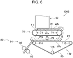
- the second web forming section 70 of a fiber body manufacturing apparatus 100B includes the first mesh belt 72 that serves as a first transport belt and two stretching rollers 74 around which the first mesh belt 72 is wound, and is configured to move the first mesh belt 72 in one direction as at least one of the stretching rollers 74 revolves.
- the transport section 112 is arranged below the second web forming section 70.
- the transport section 112 includes the second mesh belt 115 that serves as a second transport belt and a plurality of stretching rollers 116 around which the second mesh belt 115 is wound, and is configured to move the second mesh belt 115 in one direction as at least one of the stretching rollers 116 revolves.
- the transport section 112 is arranged such that the second belt surface F2 is longer in the horizontal direction than the first belt surface F1 such that the web W transported from the first belt surface F1 can be reliably delivered. Then, the angle made by the first belt surface F1 that transports the web W formed on the first mesh belt 72 and the second belt surface F2 of the second mesh belt 115 that delivers the web W transported from the first belt surface F1 is 0 degree, that is, the first belt surface F1 and the second belt surface F2 are arranged in parallel.
- the web W horizontally transported by the first belt surface F1 can be peeled off from the first belt surface F1 by its own weight of the web W at the end portion of the first belt surface F1 and can be delivered by the second belt surface F2 arranged below the first belt surface F1.
- the first surface Wa of the web W is peeled off from the first mesh belt 72, and the second surface Wb which is a surface opposite to the first surface Wa of the web W is transported in a state of being in contact with the second mesh belt 115 of the transport section 112.
- the water-applying section 79 applies water toward the first surface Wa of the web W which is in contact with the second mesh belt 115.
- the water-applying section 79 is arranged at a position facing the second belt surface F2. In the present embodiment, water is applied to the web W from above to below.
- the pressurizing section 80 is arranged downstream of the transport section 112.
- the pressurizing section 80 pressurizes the web W to which the water is applied and which is peeled off from the second mesh belt 115.
- the pressurizing section 80 of the present embodiment simultaneously pressurizes and heats the web W to which water is applied.
- the present embodiment As described above, according to the present embodiment, as in the above-described embodiment, it is possible to suppress the sticking of the web W, to which the water is applied, to the second mesh belt 115. Further, since the second web forming section 70 and the transport section 112 can be arranged so as to overlap each other in a plan view, the length of the fiber body manufacturing apparatus 100B in the horizontal direction can be further shortened.
Landscapes
- Engineering & Computer Science (AREA)
- Textile Engineering (AREA)
- Nonwoven Fabrics (AREA)
- Dry Formation Of Fiberboard And The Like (AREA)
Abstract
Description
- The present application is based on, and claims priority from
JP Application Serial Number 2021-106444, filed June 28, 2021 - The present disclosure relates to a fiber body manufacturing apparatus, a fiber body manufacturing unit, and a fiber body manufacturing method.
- In the related art, as described in
JP-A-2019-44284 - In the above-described apparatus, the humidifying section performs humidification toward one surface of the web, and the transport section comes into contact with the one surface of the web to perform transport. However, since the transport section comes into contact with one surface having a larger amount of water, there is a problem that the web sticks to the transport section.
- When the web sticks to the transport section, the web may be poorly transported or the web may be damaged.
- According to an aspect of the present disclosure, there is provided a fiber body manufacturing apparatus including: an accumulating section that forms a web by accumulating a material containing fibers on a first transport belt by a dry method; a transport section that transports the web by peeling off a first surface of the web from the first transport belt, and by bringing a second surface of the web, which is a surface opposite to the first surface peeled off from the first transport belt, into contact with a second transport belt; a water-applying section that applies water toward the first surface of the web in a state where the web is in contact with the second transport belt; and a pressurizing section that pressurizes the web to which the water is applied and which is peeled off from the second transport belt.
- According to another aspect of the present disclosure, there is provided a fiber body manufacturing unit including: an accumulating section that forms a web by accumulating a material containing fibers on a first transport belt by a dry method; a transport section that transports the web by peeling off a first surface of the web from the first transport belt, and by bringing a second surface of the web, which is a surface opposite to the first surface peeled off from the first transport belt, into contact with a second transport belt; and a water-applying section that applies water toward the first surface of the web which is in contact with the second transport belt.
- According to still another aspect of the present disclosure, there is provided a fiber body manufacturing method in a fiber body manufacturing apparatus including an accumulating section having a first transport belt configured to transport a web, a transport section having a second transport belt configured to transport the web, a water-applying section that applies water to the web, and a pressurizing section that pressurizes the web, the method including: an accumulating step of forming the web by accumulating a material containing fibers on the first transport belt by a dry method; a transport step of transporting the web by peeling off a first surface of the web from the first transport belt, and by bringing a second surface of the web, which is a surface opposite to the first surface peeled off from the first transport belt, into contact with the second transport belt; a water-applying step of applying the water toward the first surface of the web which is in contact with the second transport belt; and a pressurizing step of pressurizing the web to which the water is applied and which is peeled off from the second transport belt.
-
-
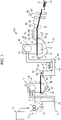
FIG. 1 is a schematic view illustrating a configuration of a fiber body manufacturing apparatus. -
FIG. 2 is a partially enlarged view illustrating a configuration of the fiber body manufacturing apparatus. -
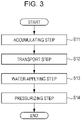
FIG. 3 is a flowchart illustrating a fiber body manufacturing method. -
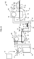
FIG. 4 is a schematic view illustrating a configuration of a fiber body manufacturing unit. -
FIG. 5 is a schematic view illustrating a configuration of another fiber body manufacturing apparatus. -
FIG. 6 is a schematic view illustrating a configuration of another fiber body manufacturing apparatus. - First, a configuration of a fiber
body manufacturing apparatus 100 will be described. The fiberbody manufacturing apparatus 100 is an apparatus for manufacturing a sheet-like fiber body S. - As illustrated in
FIG. 1 , the fiberbody manufacturing apparatus 100 includes, for example, asupply section 10, acrushing section 12, adefibration section 20, a sorting section 40, a firstweb forming section 45, arotating body 49, amixing section 50, an accumulatingsection 60, a secondweb forming section 70, atransport section 78, a water-applyingsection 79, a pressurizingsection 80, and acutting section 90. - The
supply section 10 supplies the raw material to the crushingsection 12. Thesupply section 10 is, for example, an automatic charging section for continuously charging the raw material into the crushingsection 12. The raw material supplied by thesupply section 10 is a material containing various fibers. - The fiber is not particularly limited, and a wide range of fiber materials can be used. Examples of the fiber include natural fiber (animal fiber, plant fiber) and chemical fiber (organic fiber, inorganic fiber, organic-inorganic composite fiber). More specifically, the fiber includes fibers made of cellulose, silk, wool, cotton, cannabis, kenaf, flax, ramie, jute, Manila hemp, sisal, coniferous tree, broadleaf tree, and the like, and these may be used alone, may be appropriately mixed and used, or may be used as a purified regenerated fiber.
- Examples of the raw material of the fiber include pulp, used paper, and used cloth. Further, the fiber may be subjected to various surface treatments. Further, the material of the fiber may be a pure substance or a material containing a plurality of components such as impurities and other components. Further, as the fiber, a defibrated product obtained by defibrating used paper, pulp sheet, or the like by a dry method may be used.
- The length of the fiber is not particularly limited, but in a case of one independent fiber, the length along the longitudinal direction of the fiber is 1 µm or more and 5 mm or less, preferably 2 µm or more and 3 mm or less, and more preferably 3 µm or more and 2 mm or less.
- In the fiber
body manufacturing apparatus 100, water is applied in the water-applyingsection 79, and thus the mechanical strength of a formed fiber body S can be increased by using a fiber having the ability to form hydrogen bonds. Examples of such fibers include cellulose. - The fiber content in the fiber body S is, for example, 50% by mass or more and 99.9% by mass or less, preferably 60% by mass or more and 99% by mass or less, and more preferably 70% by mass or more and 99% by mass or less. Such a content can be obtained by performing mixing when forming the mixture.
- The crushing
section 12 cuts the raw material supplied by thesupply section 10 into strips in the air such as the atmosphere. The shape and size of the strips are, for example, several centimeter square. In the illustrated example, the crushingsection 12 has a crushingblade 14, and the charged raw material can be cut by the crushingblade 14. As the crushingsection 12, for example, a shredder is used. The raw material cut by the crushingsection 12 is received by ahopper 1 and then transferred to thedefibration section 20 through apipe 2. - The
defibration section 20 defibrates the raw material cut by the crushingsection 12. Here, "defibrating" means unraveling a raw material obtained by binding a plurality of fibers into each fiber. Thedefibration section 20 also has a function of separating substances such as resin particles, ink, toner, and a blot inhibitor adhering to the raw material from the fibers. - A product that passed through the
defibration section 20 is referred to as "defibrated product". In addition to the unraveled defibrated fiber, the "defibrated product" may include resin particles separated from the fiber when the fiber is unraveled, coloring agents such as ink and toner, or additives such as blot inhibitors and paper strength enhancers. The shape of the unraveled defibrated product is a shape of a string. The unraveled defibrated product may exist in a state of not being entangled with other unraveled fibers, that is, in an independent state, or may exist in a state of being entangled with other unraveled defibrated products to form a mass shape, that is, in a state where a lump is formed. - The
defibration section 20 performs defibration by a dry method. Here, the treatment of defibrating or the like in the air such as the atmosphere, not in the liquid, is referred to as a dry method. As thedefibration section 20, for example, an impeller mill is used. Thedefibration section 20 has a function of suctioning the raw material and generating an airflow that discharges the defibrated product. Accordingly, thedefibration section 20 can suction the raw material together with the airflow from anintroduction port 22 by the airflow generated by itself, perform the defibration treatment, and transport the defibrated product to adischarge port 24. The defibrated product that passed through thedefibration section 20 is transferred to the sorting section 40 through thepipe 3. As the airflow for transporting the defibrated product from thedefibration section 20 to the sorting section 40, the airflow generated by thedefibration section 20 may be used, or an airflow generating apparatus such as a blower may be provided to use this airflow. - The sorting section 40 introduces the defibrated product defibrated by the
defibration section 20 from the introduction port 42 and sorts the defibrated product according to the length of the fibers. The sorting section 40 has, for example, adrum section 41 and ahousing section 43 that accommodates thedrum section 41 therein. As thedrum section 41, for example, a sieve is used. Thedrum section 41 has a net, and can sort out fibers or particles smaller than the size of the mesh opening of the net, that is, a first sorted product passing through the net, and fibers, undefibrated pieces, and lumps larger than the size of the mesh opening of the net, that is, a second sorted product that does not pass through the net. For example, the first sorted product is transferred to the accumulatingsection 60 through apipe 7. The second sorted product is returned from thedischarge port 44 to thedefibration section 20 through a pipe 8. Specifically, thedrum section 41 is a cylindrical sieve that is rotationally driven by a motor. As the net of thedrum section 41, for example, a wire net, an expanded metal obtained by stretching a metal plate having a cut, or a punching metal in which a hole is formed in the metal plate by a press machine or the like is used. - The first
web forming section 45 transports the first sorted product that passed through the sorting section 40 to thepipe 7. The firstweb forming section 45 includes, for example, amesh belt 46, a stretchingroller 47, and asuction mechanism 48. - The
suction mechanism 48 can suction the first sorted product dispersed in the air through the opening of the sorting section 40 onto themesh belt 46. The first sorted product is accumulated on the movingmesh belt 46 to form a web V. - Passing products that passed through the opening of the sorting section 40 are accumulated on the
mesh belt 46. Themesh belt 46 is stretched by the stretchingroller 47, and is configured such that the passing products are unlikely to pass therethrough and air is allowed to pass therethrough. Themesh belt 46 moves as the stretchingroller 47 revolves. While themesh belt 46 moves continuously, the passing products that passed through the sorting section 40 are continuously piled up, and accordingly, the web V is formed on themesh belt 46. - The
suction mechanism 48 is provided below themesh belt 46. Thesuction mechanism 48 can generate a downward airflow. By thesuction mechanism 48, the passing products dispersed in the air by the sorting section 40 can be suctioned onto themesh belt 46. Accordingly, the discharge speed from the sorting section 40 can be increased. - The web V is formed in a soft and swollen state containing a large amount of air by passing through the sorting section 40 and the first
web forming section 45. The web V accumulated on themesh belt 46 is charged into thepipe 7 and transported to the accumulatingsection 60. - The rotating
body 49 can cut the web V. In the illustrated example, the rotatingbody 49 has abase portion 49a and aprotrusion portion 49b protruding from thebase portion 49a. Theprotrusion portion 49b has, for example, a plate-like shape. In the illustrated example, fourprotrusion portions 49b are provided, and fourprotrusion portions 49b are provided at equal intervals. By rotating thebase portion 49a in a direction R, theprotrusion portion 49b can rotate around thebase portion 49a as an axis. By cutting the web V by the rotatingbody 49, for example, the fluctuation of the amount of the defibrated product per unit time supplied to the accumulatingsection 60 can be reduced. - The rotating
body 49 is provided in the vicinity of the firstweb forming section 45. In the illustrated example, the rotatingbody 49 is provided in the vicinity of the stretchingroller 47a positioned downstream in the path of the web V. The rotatingbody 49 is provided at a position where theprotrusion portion 49b can come into contact with the web V and does not come into contact with themesh belt 46 on which the web V is accumulated. Accordingly, it is possible to suppress abrasion of themesh belt 46 by theprotrusion portion 49b. The shortest distance between theprotrusion portion 49b and themesh belt 46 is, for example, 0.05 mm or more and 0.5 mm or less. This is the distance at which themesh belt 46 can cut the web V without being damaged. - The mixing
section 50 mixes, for example, the first sorted product that passed through the sorting section 40 and the binder. The mixingsection 50 has, for example, abinder supply section 52 that supplies the binder, apipe 54 for transporting the first sorted product and the binder, and ablower 56. In the illustrated example, the binder is supplied from thebinder supply section 52 to thepipe 54 through thehopper 9. Thepipe 54 is continuous with thepipe 7. - In the
mixing section 50, an airflow is generated by theblower 56, and the first sorted product and the binder can be transported while being mixed in thepipe 54. The mechanism for mixing the first sorted product and the binder is not particularly limited, and may be agitated by a blade that rotates at high speed, or may use rotation of a container such as a V-type mixer. - As the
binder supply section 52, a screw feeder, a disc feeder, or the like is used. - The binder supplied from the
binder supply section 52 is, for example, starch or dextrin. Starch is a polymer in which a plurality of α-glucose molecules are polymerized by glycosidic bonds. The starch may be linear or may contain branches. - As the starch, those derived from various plants can be used. Raw materials for starch include grains such as corn, wheat, and rice, beans such as broad beans, mung beans, and red beans, tubers such as potatoes, sweet potatoes, and tapioca, wild grasses such as Erythronium japonicum, bracken, and kudzu, and palms such as sago palm.
- Further, processed starch or modified starch may be used as the starch. Examples of the processed starch include acetylated adipic acid cross-linked starch, acetylated starch, oxidized starch, octenyl succinate starch sodium, hydroxypropyl starch, hydroxypropylated phosphoric acid cross-linked starch, phosphorylated starch, phosphoric acid esterified phosphoric acid cross-linked starch, urea phosphorylated esterified starch, sodium starch glycolate, and high amylose corn starch. Further, as the dextrin that serves as the modified starch, those obtained by processing or modifying the starch can be preferably used.
- In the fiber
body manufacturing apparatus 100, by using starch or dextrin as a binder, at least one of gelatinization of the binder and hydrogen bonds between the fibers occurs by being pressurized and heated after water is applied, and the fiber body S can be given sufficient strength. Meanwhile, when the fiber body S can be given sufficient strength only by hydrogen bonds between the fibers, the fiber body can be manufactured without using a binder. When the fiber body is manufactured without using the binder, the fiberbody manufacturing apparatus 100 may not include thebinder supply section 52. - The content of starch or dextrin in the fiber body S is, for example, 0.1% by mass or more and 50% by mass or less, preferably 1% by mass or more and 40% by mass or less, and more preferably 1% by mass or more and 30% by mass or less. Such a content can be obtained by performing mixing when forming the mixture.
- In addition, in the
binder supply section 52, in addition to the binder, in accordance with the type of the fiber body S to be manufactured, a colorant for coloring the fibers, a coagulation inhibitor for suppressing coagulation of fibers or coagulation of binder, a flame retardant for making fibers and the like unlikely to burn, and the like, may be included. The mixture that passed through the mixingsection 50 is transferred to the accumulatingsection 60 through thepipe 54. - The accumulating
section 60 introduces the mixture that passed through the mixingsection 50 from anintroduction port 62, unravels the entangled defibrated product, and disperses the unraveled defibrated product in the air to make the product fall. Accordingly, the accumulatingsection 60 can uniformly accumulate the mixture on the secondweb forming section 70. - The accumulating
section 60 has, for example, adrum section 61 and ahousing section 63 that accommodates thedrum section 61 therein. As thedrum section 61, a rotating cylindrical sieve is used. Thedrum section 61 has a net and makes fibers or particles smaller than the size of the mesh opening of the net, which are contained in the mixture that passed through the mixingsection 50, fall. The configuration of thedrum section 61 is, for example, the same as the configuration of thedrum section 41. - The "sieve" of the
drum section 61 may not have a function of sorting a specific object. In other words, the "sieve" used as thedrum section 61 means a sieve provided with a net, and thedrum section 61 may make all of the mixture introduced into thedrum section 61 fall. - The second
web forming section 70 accumulates the passing products that passed through the accumulatingsection 60 to form the web W. The secondweb forming section 70 includes, for example, afirst mesh belt 72 that serves as a first transport belt, a stretchingroller 74, and asuction mechanism 76. - Passing products that passed through the opening of the accumulating
section 60 are accumulated on thefirst mesh belt 72. Thefirst mesh belt 72 is stretched by the stretchingroller 74, and is configured such that the passing products are unlikely to pass therethrough and air is allowed to pass therethrough. Thefirst mesh belt 72 moves as the stretchingroller 74 revolves. While thefirst mesh belt 72 moves continuously, the passing products that passed through the accumulatingsection 60 are continuously piled up, and accordingly, the web W is formed on thefirst mesh belt 72. - The
suction mechanism 76 is provided below thefirst mesh belt 72. Thesuction mechanism 76 can generate a downward airflow. By thesuction mechanism 76, the mixture dispersed in the air by the accumulatingsection 60 can be suctioned onto thefirst mesh belt 72. Accordingly, the discharge speed from the accumulatingsection 60 can be increased. Furthermore, thesuction mechanism 76 can form a downflow in the falling path of the mixture, and can prevent the defibrated product and the binder from being entangled during the fall. - As described above, the web W in a soft and swollen state containing a large amount of air is formed by passing through the accumulating
section 60 and the secondweb forming section 70. - The
transport section 78 is arranged downstream of thefirst mesh belt 72 in the transport direction of the web W. Thetransport section 78 peels off the web W on thefirst mesh belt 72 from thefirst mesh belt 72 and transports the web W toward the pressurizingsection 80. As illustrated inFIG. 2 , thetransport section 78 has asecond mesh belt 78a that serves as a second transport belt, aroller 78b, and asuction mechanism 78c. Thesecond mesh belt 78a is stretched by theroller 78b, and is configured such that the air is allowed to pass therethrough. Thesecond mesh belt 78a is configured to be movable by the revolution of theroller 78b. Thesuction mechanism 78c is arranged at a position facing the web W with thesecond mesh belt 78a interposed therebetween. Thesuction mechanism 78c includes a blower, and generates an upward airflow in thesecond mesh belt 78a by the suction force of the blower. The web W is suctioned by this airflow. - Accordingly, a first surface Wa of the web W is peeled off from the
first mesh belt 72, and a second surface Wb which is a surface opposite to the first surface Wa peeled off from thefirst mesh belt 72 can be adsorbed to thesecond mesh belt 78a. The web W adsorbed to thesecond mesh belt 78a is transported in a state of being in contact with thesecond mesh belt 78a. - The water-applying
section 79 is arranged below thetransport section 78. The water-applyingsection 79 applies water toward the first surface Wa of the web W which is in contact with thesecond mesh belt 78a. In the water-applyingsection 79, as the water, for example, water vapor or mist is applied to the web W. Accordingly, water can be uniformly applied to the web W. - The water-applying
section 79 applies water from below the web W toward the first surface Wa. In the present embodiment, acontainer 79a capable of storing water and apiezoelectric vibrator 79b arranged at the bottom portion of thecontainer 79a are provided. The upper portion of thecontainer 79a is opened, and thecontainer 79a is arranged such that the opening faces the first surface Wa side of the web W. By driving thepiezoelectric vibrator 79b, ultrasonic waves are generated in the water and mist is generated in thecontainer 79a. The generated mist is supplied to the web W through the opening of thecontainer 79a. By applying water from below the web W, water droplets do not fall on the web W even when dew condensation is generated in the water-applyingsection 79 or in the vicinity thereof. In other words, for example, when water is applied to the web W from above, there is a concern that the water adheres to the water-applyingsection 79 or the vicinity thereof and falls as water droplets, and the water droplets adhere to the web. In this case, the application of water to the web W becomes non-uniform. However, in the present embodiment, the falling of water droplets and the like is suppressed, and it is possible to avoid affecting the quality of the fiber body S. - Further, the
suction mechanism 78c of thetransport section 78 is arranged at a position facing the water-applyingsection 79 with thesecond mesh belt 78a interposed therebetween. Accordingly, the airflow containing water generated in the water-applyingsection 79 by thesuction mechanism 78c can pass through the inside of the web W and apply water to the inside of the web W. In other words, thesuction mechanism 78c is arranged so as to face a part of thefirst mesh belt 72 of the secondweb forming section 70 and thecontainer 79a of the water-applyingsection 79. Accordingly, thecommon suction mechanism 78c has a function of peeling off the web W from thefirst mesh belt 72 and adsorbing the web W to thesecond mesh belt 78a and a function of applying water to the inside of the web W. Therefore, the configuration of the fiberbody manufacturing apparatus 100 can be simplified. - In the present embodiment, water is applied from the first surface Wa side opposite to the second surface Wb of the web W which is in contact with the
second mesh belt 78a, and thus the second surface Wb side can be transported with a weaker adhesive force than the first surface Wa side. Therefore, it is possible to suppress the sticking of the web W, to which the water is applied, to thesecond mesh belt 78a. - The water content of the web W to which water was applied in the water-applying
section 79 is preferably 12% by mass or more and 40% by mass or less. With the specified web water content, hydrogen bonds between fibers can be effectively formed and the strength of the fiber body S can be increased. Here, the web W having a water content of 12% by mass or more is generally in a state of being easily attached to the transport section. However, in the present embodiment, water is applied to the web W from the first surface Wa side opposite to the second surface Wb of the web W which is in contact with thesecond mesh belt 78a, and accordingly, even on the web W which is easily attached to the transport section, the sticking to thesecond mesh belt 78a can be suppressed. Further, by specifying the water content of the web W to be 40% by mass or less, the amount of water used can be reduced. - Furthermore, the web W containing a binder (starch or dextrin) is generally in a state of being easily attached to the transport section, but in the present embodiment, even in a case of such a web W, the sticking to the
second mesh belt 78a is suppressed, the binding force between the fibers is increased by the binder, and the strength of the fiber body S can be increased. - The pressurizing
section 80 is arranged downstream of thetransport section 78 and the water-applyingsection 79. The web W to which the water is applied is transported to the pressurizingsection 80. - The pressurizing
section 80 pressurizes the web W to which the water is applied and which is peeled off from thesecond mesh belt 78a. The pressurizingsection 80 of the present embodiment simultaneously pressurizes and heats the web W to which water is applied. Accordingly, the water contained in the web W evaporates after the temperature rises, and the thickness of the web W becomes thin to increase the fiber density. The temperature of the water and the binder rises due to heat, the fiber density increases due to the pressure, and accordingly, the binder is gelatinized, and then the water evaporates to bind the plurality of fibers to each other through the gelatinized binder. Furthermore, the water evaporates due to heat and the fiber density increases due to pressure, and accordingly, the plurality of fibers are bound to each other by hydrogen bonds. Accordingly, it is possible to form the sheet-like fiber body S having better mechanical strength. - The pressurizing
section 80 of the present embodiment has a pressurizingheating section 84 that pressurizes and heats the web W. The pressurizingheating section 84 can be configured by using, for example, a heating roller or a heat press molding machine. In the illustrated example, the pressurizingheating section 84 is a pair ofheating rollers 86. The number ofheating rollers 86 is not particularly limited. The pressurizingheating section 84 can simultaneously pressurize and heat the web W. Further, the configuration of the fiberbody manufacturing apparatus 100 can be simplified. - As illustrated in
FIG. 1 , the cuttingsection 90 cuts the fiber body S molded by the pressurizingsection 80. In the illustrated example, the cuttingsection 90 includes afirst cutting section 92 that cuts the fiber body S in a direction intersecting the transport direction of the fiber body S, and asecond cutting section 94 that cuts the fiber body S in a direction parallel to the transport direction. Thesecond cutting section 94 cuts, for example, the fiber body S that passed through thefirst cutting section 92. - As a result, a single-cut fiber body S having a predetermined size is molded. The cut single-cut fiber body S is discharged to a
discharge receiving section 96. - Next, a fiber body manufacturing method will be described.
- In the present embodiment, a method for manufacturing the fiber body S by the fiber
body manufacturing apparatus 100 will be described. - As illustrated in
FIG. 3 , in the accumulating step (step S11), a material containing fibers is accumulated on thefirst mesh belt 72 by a dry method to form the web W. - Specifically, a mixture containing defibrated fibers and a binder (starch or dextrin) is accumulated by a dry method to form the web W. The fiber is a defibrated product defibrated by the
defibration section 20, the binder is supplied from thebinder supply section 52, and the mixture is formed by the mixingsection 50. Then, the accumulatingsection 60 and the secondweb forming section 70 accumulate the mixture by a dry method to form the web W. - Next, in the transport step (step S12), the first surface Wa of the web W is peeled off from the
first mesh belt 72, and the second surface Wb, which is a surface opposite to the first surface Wa peeled off from thefirst mesh belt 72, is brought into contact with thesecond mesh belt 78a to transport the web W. - Specifically, the
suction mechanism 78c of thetransport section 78 generates an upward airflow in thesecond mesh belt 78a to suction the web W. Accordingly, the first surface Wa of the web W is peeled off from thefirst mesh belt 72, and the web W is transported in a state where the second surface Wb is in contact with thesecond mesh belt 78a. - Then, in the water-applying step (step S13), water is applied toward the first surface Wa of the web W which is in contact with the
second mesh belt 78a. In other words, in the present embodiment, water is applied to the web W during the period in which the web W is being transported in the transport step. - Specifically, water is supplied from the water-applying
section 79. In this step, water vapor or mist is applied to the web W. By doing so, it is possible to more uniformly apply water to the web W, and the fiber body S can be manufactured with a simpler apparatus configuration. The amount of water applied in the water-applying step can be managed by, for example, the water content of the web W. The water content of the web W to which water was applied in the water-applying step is preferably 12% by mass or more and 40% by mass or less. When the amount of water applied is approximately this level, it is possible to manufacture the fiber body S having higher strength while suppressing the amount of energy such as electric power required for heating and drying the web W. - Further, by applying water toward the first surface Wa side of the web W which is in contact with the
second mesh belt 78a, the second surface Wb side has a weaker adhesive force than the first surface Wa side, and thus it is possible to suppress the sticking of the web W, to which the water is applied, to thesecond mesh belt 78a. - Then, in the pressurizing step (step S14), water is applied, and the web W peeled off from the
second mesh belt 78a is pressurized. - Specifically, a pair of
heating rollers 86 of the pressurizingsection 80 applies pressure to the web W to thin the web and increase the fiber density in the web W. The pressure applied to the web W is preferably 0.1 MPa or more and 15 MPa or less, more preferably 0.2 MPa or more and 10 MPa or less, and further preferably 0.4 MPa or more and 8 MPa or less. When the pressure applied to the web W in the pressurizing step is within such a range, the deterioration of the fiber can be suppressed, and the fiber body S having good strength can be manufactured again using the defibrated product obtained by defibrating the manufactured fiber body S as a raw material. - Further, in the pressurizing step, heat is applied to the web W to evaporate the water contained in the web W. In the pressurizing step, the web W is heated so as to have a temperature of 60°C or higher and 100°C or lower. By doing so, the time required for the pressurizing step can be reduced, and the fiber body S can be manufactured with lower energy.
- In the pressurizing step, since a relatively low pressure is applied to the web W, a small manufacturing apparatus can be used, and since the damage to the fiber is relatively small, the fiber body S is defibrated again to make it easy to manufacture a new fiber body S.
- Further, in the pressurizing step, since the web W is heated to a relatively low temperature, it is easy to form hydrogen bonds between the fibers and it is easy to secure the strength of the fiber body S. Further, since the binder can be gelatinized, the fibers can be bound to each other by the binder, and the strength of the fiber body S can be obtained.
- Next, the configuration of a fiber
body manufacturing unit 1000 will be described. - As illustrated in
FIG. 4 , the fiberbody manufacturing unit 1000 includes the accumulatingsection 60 that forms the web W by accumulating a material containing fibers on thefirst mesh belt 72 that serves as a first transport belt; thetransport section 78 that transports the web by peeling off the first surface Wa of the web W from thefirst mesh belt 72, and by bringing the second surface Wb, which is a surface opposite to the first surface Wa peeled off from thefirst mesh belt 72, into contact with thesecond mesh belt 78a that serves as a second transport belt; and the water-applyingsection 79 that applies water toward the first surface Wa of the web W which is in contact with thesecond mesh belt 78a. - The same configurations as those in the first embodiment will be given the same reference numerals, and repeating description will be omitted.
- As described above, the fiber
body manufacturing unit 1000 can suppress the sticking of the web W, to which the water is applied, to the second transport belt, as in the above-described embodiment. - In addition to the above-described configuration, the fiber
body manufacturing unit 1000 includes, for example, thesupply section 10, the crushingsection 12, thedefibration section 20, the sorting section 40, the firstweb forming section 45, the rotatingbody 49, the mixingsection 50, and the like. - Next, a third embodiment will be described.
- The same configurations as those in the first embodiment will be given the same reference numerals, and repeating description will be omitted.
- In the first embodiment, the configuration in which the web W is brought into contact with the
second mesh belt 78a and transported by thesuction mechanism 78c of thetransport section 78 was described, but the configuration is not limited thereto, and the configuration that does not include thesuction mechanism 78c may also be adopted. - As illustrated in
FIG. 5 , a fiberbody manufacturing apparatus 100A of the present embodiment includes the accumulatingsection 60, the secondweb forming section 70, atransport section 102, the water-applyingsection 79, and the pressurizingsection 80. - The web W formed on the
first mesh belt 72 as the first transport belt is transported by the rotational movement of thefirst mesh belt 72. Then, the web W transported to the downstream end portion (a part corresponding to a stretchingroller 74b) of thefirst mesh belt 72 is transported downward while being stuck to thefirst mesh belt 72. Here, the angle formed by a first belt surface F1 on thefirst mesh belt 72 and a third belt surface F3 of thefirst mesh belt 72 stretched between the stretchingroller 74b and the stretchingroller 74c is less than 90 degrees. Therefore, the web W is peeled off from the third belt surface F3 by its own weight. As a result, the web W is delivered from thefirst mesh belt 72 to thetransport section 102 and transported. Thetransport section 102 is arranged below the first belt surface F1 on thefirst mesh belt 72. - In the
transport section 102, asecond mesh belt 105 that serves as a second transport belt stretched by a plurality of stretchingrollers 106 is arranged. Then, when at least one of the stretchingrollers 106 revolves, thesecond mesh belt 105 moves in one direction. Then, the web W is delivered from the first belt surface F1 of thefirst mesh belt 72 to the second belt surface F2 of thetransport section 102, and is transported in the transport direction (arrows in the drawing). Here, the transport direction of the second belt surface F2 is downward. At this time, the first surface Wa of the web W is peeled off from thefirst mesh belt 72, and the second surface Wb which is a surface opposite to the first surface Wa of the web W is transported in a state of being in contact with thesecond mesh belt 105 of thetransport section 102. - The second belt surface F2 is positioned downstream of the first belt surface F1 in the transport direction of the web W. A first angle θ formed by the first belt surface F1 on the
first mesh belt 72 and the second belt surface F2 on thesecond mesh belt 105 is set to be less than 90 degrees. - When the web W accumulated on the first belt surface F1 is transported to the second belt surface F2 side, the web W is peeled off from the first belt surface F1 by its own weight at the end portion (around the area beyond the stretching
roller 74b in the transport direction) of the first belt surface F1, and is delivered to the second belt surface F2 arranged downward in the vertical direction. Accordingly, when the web W is transported from the first belt surface F1 to the second belt surface F2, equipment such as a suction mechanism and a blade for peeling off the web W is not required at the end portion of the first belt surface F1, and thus the transport configuration can be simplified. - The water-applying
section 79 applies water toward the first surface Wa of the web W which is in contact with thesecond mesh belt 105. The water-applyingsection 79 is arranged at a position facing the second belt surface F2. - The pressurizing
section 80 is arranged downstream of thetransport section 102. The pressurizingsection 80 pressurizes the web W to which the water is applied and which is peeled off from thesecond mesh belt 105. The pressurizingsection 80 of the present embodiment simultaneously pressurizes and heats the web W to which water is applied. - As described above, according to the present embodiment, as in the above-described embodiment, the
second mesh belt 105 supports the second surface Wb which is a surface opposite to the first surface Wa, to which water is applied by the water-applyingsection 79, and thus it is possible to suppress the sticking of the web W, to which the water is applied, to the second transport belt. - Next, a fourth embodiment will be described.
- The same configurations as those in the first embodiment will be given the same reference numerals, and repeating description will be omitted.
- In the third embodiment, the upper limit of the first angle θ formed by the first belt surface F1 and the second belt surface F2 is set to less than 90 degrees, but the lower limit of the first angle θ formed by the first belt surface F1 and the second belt surface F2 may be 0 degree.
- As illustrated in
FIG. 6 , the secondweb forming section 70 of a fiberbody manufacturing apparatus 100B includes thefirst mesh belt 72 that serves as a first transport belt and two stretchingrollers 74 around which thefirst mesh belt 72 is wound, and is configured to move thefirst mesh belt 72 in one direction as at least one of the stretchingrollers 74 revolves. Further, thetransport section 112 is arranged below the secondweb forming section 70. In addition, thetransport section 112 includes thesecond mesh belt 115 that serves as a second transport belt and a plurality of stretchingrollers 116 around which thesecond mesh belt 115 is wound, and is configured to move thesecond mesh belt 115 in one direction as at least one of the stretchingrollers 116 revolves. Here, thetransport section 112 is arranged such that the second belt surface F2 is longer in the horizontal direction than the first belt surface F1 such that the web W transported from the first belt surface F1 can be reliably delivered. Then, the angle made by the first belt surface F1 that transports the web W formed on thefirst mesh belt 72 and the second belt surface F2 of thesecond mesh belt 115 that delivers the web W transported from the first belt surface F1 is 0 degree, that is, the first belt surface F1 and the second belt surface F2 are arranged in parallel. Even in this manner, the web W horizontally transported by the first belt surface F1 can be peeled off from the first belt surface F1 by its own weight of the web W at the end portion of the first belt surface F1 and can be delivered by the second belt surface F2 arranged below the first belt surface F1. At this time, the first surface Wa of the web W is peeled off from thefirst mesh belt 72, and the second surface Wb which is a surface opposite to the first surface Wa of the web W is transported in a state of being in contact with thesecond mesh belt 115 of thetransport section 112. - The water-applying
section 79 applies water toward the first surface Wa of the web W which is in contact with thesecond mesh belt 115. The water-applyingsection 79 is arranged at a position facing the second belt surface F2. In the present embodiment, water is applied to the web W from above to below. - The pressurizing
section 80 is arranged downstream of thetransport section 112. The pressurizingsection 80 pressurizes the web W to which the water is applied and which is peeled off from thesecond mesh belt 115. The pressurizingsection 80 of the present embodiment simultaneously pressurizes and heats the web W to which water is applied. - As described above, according to the present embodiment, as in the above-described embodiment, it is possible to suppress the sticking of the web W, to which the water is applied, to the
second mesh belt 115. Further, since the secondweb forming section 70 and thetransport section 112 can be arranged so as to overlap each other in a plan view, the length of the fiberbody manufacturing apparatus 100B in the horizontal direction can be further shortened.
Claims (10)
- A fiber body manufacturing apparatus comprising:an accumulating section that forms a web by accumulating a material containing fibers on a first transport belt by a dry method;a transport section that transports the web by peeling off a first surface of the web from the first transport belt, and by bringing a second surface of the web, which is a surface opposite to the first surface peeled off from the first transport belt, into contact with a second transport belt;a water-applying section that applies water toward the first surface of the web in a state where the web is in contact with the second transport belt; anda pressurizing section that pressurizes the web to which the water is applied and which is peeled off from the second transport belt.
- The fiber body manufacturing apparatus according to claim 1, wherein
in the water-applying section, water vapor or mist is applied to the web as the water. - The fiber body manufacturing apparatus according to claim 1, wherein
the transport section includes a suction mechanism for adsorbing the web to the second transport belt. - The fiber body manufacturing apparatus according to claim 3, wherein
the suction mechanism is arranged at a position facing the water-applying section with the second transport belt interposed therebetween. - The fiber body manufacturing apparatus according to claim 1, wherein
the water-applying section applies the water toward the first surface from below the web. - The fiber body manufacturing apparatus according to claim 1, wherein
a water content of the web to which the water is applied is 12% by mass or more and 40% by mass or less. - The fiber body manufacturing apparatus according to claim 1, wherein
in the accumulating section, the material containing the fibers and a binder is accumulated. - The fiber body manufacturing apparatus according to claim 1, wherein
the pressurizing section simultaneously pressurizes and heats the web. - A fiber body manufacturing method in a fiber body manufacturing apparatus including an accumulating section having a first transport belt configured to transport a web, a transport section having a second transport belt configured to transport the web, a water-applying section that applies water to the web, and a pressurizing section that pressurizes the web, the method comprising:an accumulating step of forming the web by accumulating a material containing fibers on the first transport belt by a dry method;a transport step of transporting the web by peeling off a first surface of the web from the first transport belt, and by bringing a second surface of the web, which is a surface opposite to the first surface peeled off from the first transport belt, into contact with the second transport belt;a water-applying step of applying the water toward the first surface of the web which is in contact with the second transport belt; anda pressurizing step of pressurizing the web to which the water is applied and which is peeled off from the second transport belt.
- A fiber body manufacturing unit comprising:an accumulating section that forms a web by accumulating a material containing fibers on a first transport belt by a dry method;a transport section that transports the web by peeling off a first surface of the web from the first transport belt, and by bringing a second surface of the web, which is a surface opposite to the first surface peeled off from the first transport belt, into contact with a second transport belt; anda water-applying section that applies water toward the first surface of the web which is in contact with the second transport belt.
Applications Claiming Priority (1)
| Application Number | Priority Date | Filing Date | Title |
|---|---|---|---|
| JP2021106444A JP7608981B2 (en) | 2021-06-28 | 2021-06-28 | Fibrous body manufacturing apparatus, fibrous body manufacturing unit, and fibrous body manufacturing method |
Publications (1)
| Publication Number | Publication Date |
|---|---|
| EP4112809A1 true EP4112809A1 (en) | 2023-01-04 |
Family
ID=82321351
Family Applications (1)
| Application Number | Title | Priority Date | Filing Date |
|---|---|---|---|
| EP22181197.9A Pending EP4112809A1 (en) | 2021-06-28 | 2022-06-27 | Fiber body manufacturing apparatus, fiber body manufacturing unit, and fiber body manufacturing method |
Country Status (4)
| Country | Link |
|---|---|
| US (1) | US11920300B2 (en) |
| EP (1) | EP4112809A1 (en) |
| JP (1) | JP7608981B2 (en) |
| CN (1) | CN115595728A (en) |
Citations (3)
| Publication number | Priority date | Publication date | Assignee | Title |
|---|---|---|---|---|
| EP3418435A1 (en) * | 2016-02-18 | 2018-12-26 | Seiko Epson Corporation | Sheet production device |
| JP2019044284A (en) | 2017-08-31 | 2019-03-22 | セイコーエプソン株式会社 | Sheet manufacturing apparatus, sheet manufacturing system, sheet manufacturing apparatus control method, and sheet manufacturing method |
| JP2021106444A (en) | 2019-12-26 | 2021-07-26 | 日本電産トーソク株式会社 | Electric actuator |
Family Cites Families (10)
| Publication number | Priority date | Publication date | Assignee | Title |
|---|---|---|---|---|
| US8394316B2 (en) * | 2010-08-12 | 2013-03-12 | Johnson & Johnson Do Brasil Industria E Comercio Produtos Para Saude Ltda. Rodovia | Method for making a fibrous article |
| JP6149662B2 (en) * | 2013-10-03 | 2017-06-21 | セイコーエプソン株式会社 | Sheet manufacturing apparatus and sheet manufacturing method |
| JP2016065339A (en) * | 2014-09-25 | 2016-04-28 | セイコーエプソン株式会社 | Sheet manufacturing device and sheet manufacturing method |
| JP6417591B2 (en) * | 2014-11-26 | 2018-11-07 | セイコーエプソン株式会社 | Sheet manufacturing apparatus and sheet manufacturing method |
| JP6589298B2 (en) * | 2015-03-04 | 2019-10-16 | セイコーエプソン株式会社 | Sheet manufacturing apparatus and sheet manufacturing method |
| TW201700831A (en) * | 2015-04-06 | 2017-01-01 | Seiko Epson Corp | Sheet manufacturing apparatus and sheet manufacturing method |
| EP3346036B1 (en) * | 2015-09-04 | 2021-07-07 | Seiko Epson Corporation | Sheet production apparatus and sheet production method |
| JP2019105012A (en) * | 2017-12-14 | 2019-06-27 | セイコーエプソン株式会社 | Fiber processing unit and regenerator of raw material of fiber |
| JP7172518B2 (en) * | 2018-11-30 | 2022-11-16 | セイコーエプソン株式会社 | Fiber deposition device and sheet manufacturing device |
| JP7414396B2 (en) * | 2018-12-28 | 2024-01-16 | ユニ・チャーム株式会社 | Manufacturing method for sheet members |
-
2021
- 2021-06-28 JP JP2021106444A patent/JP7608981B2/en active Active
-
2022
- 2022-06-24 CN CN202210729837.4A patent/CN115595728A/en active Pending
- 2022-06-27 US US17/809,018 patent/US11920300B2/en active Active
- 2022-06-27 EP EP22181197.9A patent/EP4112809A1/en active Pending
Patent Citations (3)
| Publication number | Priority date | Publication date | Assignee | Title |
|---|---|---|---|---|
| EP3418435A1 (en) * | 2016-02-18 | 2018-12-26 | Seiko Epson Corporation | Sheet production device |
| JP2019044284A (en) | 2017-08-31 | 2019-03-22 | セイコーエプソン株式会社 | Sheet manufacturing apparatus, sheet manufacturing system, sheet manufacturing apparatus control method, and sheet manufacturing method |
| JP2021106444A (en) | 2019-12-26 | 2021-07-26 | 日本電産トーソク株式会社 | Electric actuator |
Also Published As
| Publication number | Publication date |
|---|---|
| US11920300B2 (en) | 2024-03-05 |
| CN115595728A (en) | 2023-01-13 |
| US20220412004A1 (en) | 2022-12-29 |
| JP2023004619A (en) | 2023-01-17 |
| JP7608981B2 (en) | 2025-01-07 |
Similar Documents
| Publication | Publication Date | Title |
|---|---|---|
| CN114318676B (en) | Manufacturing method of formed body | |
| EP4112810A1 (en) | Fiber body manufacturing method | |
| EP4339344B1 (en) | Sheet manufacturing apparatus | |
| CN114381960A (en) | Manufacturing method of material for injection molding and material for injection molding | |
| CN114181435A (en) | Composite, formed body, and method for producing the formed body | |
| US11920300B2 (en) | Fiber body manufacturing apparatus, fiber body manufacturing unit, and fiber body manufacturing method | |
| US12601115B2 (en) | Sheet manufacturing apparatus and sheet manufacturing method | |
| EP4321680B1 (en) | Sheet manufacturing apparatus | |
| US20240052570A1 (en) | Sheet manufacturing apparatus | |
| US11807988B2 (en) | Sheet manufacturing method and sheet manufacturing apparatus | |
| CN115748100A (en) | Sheet manufacturing method and sheet manufacturing device | |
| US11753769B2 (en) | Sheet manufacturing method and sheet manufacturing apparatus | |
| US12553183B2 (en) | Sheet manufacturing apparatus and sheet manufacturing method | |
| US20240102243A1 (en) | Sheet manufacturing apparatus | |
| JP2023019437A (en) | cushioning material | |
| US20230150231A1 (en) | Buffer material | |
| US20230147271A1 (en) | Buffer material | |
| JP2025014642A (en) | Method for controlling sheet manufacturing apparatus |
Legal Events
| Date | Code | Title | Description |
|---|---|---|---|
| PUAI | Public reference made under article 153(3) epc to a published international application that has entered the european phase |
Free format text: ORIGINAL CODE: 0009012 |
|
| STAA | Information on the status of an ep patent application or granted ep patent |
Free format text: STATUS: THE APPLICATION HAS BEEN PUBLISHED |
|
| AK | Designated contracting states |
Kind code of ref document: A1 Designated state(s): AL AT BE BG CH CY CZ DE DK EE ES FI FR GB GR HR HU IE IS IT LI LT LU LV MC MK MT NL NO PL PT RO RS SE SI SK SM TR |
|
| STAA | Information on the status of an ep patent application or granted ep patent |
Free format text: STATUS: REQUEST FOR EXAMINATION WAS MADE |
|
| 17P | Request for examination filed |
Effective date: 20230208 |
|
| RBV | Designated contracting states (corrected) |
Designated state(s): AL AT BE BG CH CY CZ DE DK EE ES FI FR GB GR HR HU IE IS IT LI LT LU LV MC MK MT NL NO PL PT RO RS SE SI SK SM TR |
|
| GRAP | Despatch of communication of intention to grant a patent |
Free format text: ORIGINAL CODE: EPIDOSNIGR1 |
|
| STAA | Information on the status of an ep patent application or granted ep patent |
Free format text: STATUS: GRANT OF PATENT IS INTENDED |
|
| INTG | Intention to grant announced |
Effective date: 20260105 |
|
| GRAS | Grant fee paid |
Free format text: ORIGINAL CODE: EPIDOSNIGR3 |
|
| GRAA | (expected) grant |
Free format text: ORIGINAL CODE: 0009210 |
|
| STAA | Information on the status of an ep patent application or granted ep patent |
Free format text: STATUS: THE PATENT HAS BEEN GRANTED |