EP4112797A1 - Drum bypass control - Google Patents
Drum bypass control Download PDFInfo
- Publication number
- EP4112797A1 EP4112797A1 EP22177103.3A EP22177103A EP4112797A1 EP 4112797 A1 EP4112797 A1 EP 4112797A1 EP 22177103 A EP22177103 A EP 22177103A EP 4112797 A1 EP4112797 A1 EP 4112797A1
- Authority
- EP
- European Patent Office
- Prior art keywords
- drum
- tub
- seal
- arm
- gap
- Prior art date
- Legal status (The legal status is an assumption and is not a legal conclusion. Google has not performed a legal analysis and makes no representation as to the accuracy of the status listed.)
- Withdrawn
Links
Images




Classifications
-
- D—TEXTILES; PAPER
- D06—TREATMENT OF TEXTILES OR THE LIKE; LAUNDERING; FLEXIBLE MATERIALS NOT OTHERWISE PROVIDED FOR
- D06F—LAUNDERING, DRYING, IRONING, PRESSING OR FOLDING TEXTILE ARTICLES
- D06F37/00—Details specific to washing machines covered by groups D06F21/00 - D06F25/00
-
- D—TEXTILES; PAPER
- D06—TREATMENT OF TEXTILES OR THE LIKE; LAUNDERING; FLEXIBLE MATERIALS NOT OTHERWISE PROVIDED FOR
- D06F—LAUNDERING, DRYING, IRONING, PRESSING OR FOLDING TEXTILE ARTICLES
- D06F25/00—Washing machines with receptacles, e.g. perforated, having a rotary movement, e.g. oscillatory movement, the receptacle serving both for washing and for centrifugally separating water from the laundry and having further drying means, e.g. using hot air
-
- D—TEXTILES; PAPER
- D06—TREATMENT OF TEXTILES OR THE LIKE; LAUNDERING; FLEXIBLE MATERIALS NOT OTHERWISE PROVIDED FOR
- D06F—LAUNDERING, DRYING, IRONING, PRESSING OR FOLDING TEXTILE ARTICLES
- D06F37/00—Details specific to washing machines covered by groups D06F21/00 - D06F25/00
- D06F37/20—Mountings, e.g. resilient mountings, for the rotary receptacle, motor, tub or casing; Preventing or damping vibrations
- D06F37/22—Mountings, e.g. resilient mountings, for the rotary receptacle, motor, tub or casing; Preventing or damping vibrations in machines with a receptacle rotating or oscillating about a horizontal axis
-
- D—TEXTILES; PAPER
- D06—TREATMENT OF TEXTILES OR THE LIKE; LAUNDERING; FLEXIBLE MATERIALS NOT OTHERWISE PROVIDED FOR
- D06F—LAUNDERING, DRYING, IRONING, PRESSING OR FOLDING TEXTILE ARTICLES
- D06F23/00—Washing machines with receptacles, e.g. perforated, having a rotary movement, e.g. oscillatory movement, the receptacle serving both for washing and for centrifugally separating water from the laundry
- D06F23/06—Washing machines with receptacles, e.g. perforated, having a rotary movement, e.g. oscillatory movement, the receptacle serving both for washing and for centrifugally separating water from the laundry and rotating or oscillating about an inclined axis
- D06F23/065—Washing machines with receptacles, e.g. perforated, having a rotary movement, e.g. oscillatory movement, the receptacle serving both for washing and for centrifugally separating water from the laundry and rotating or oscillating about an inclined axis with a rotatable imperforate tub
-
- D—TEXTILES; PAPER
- D06—TREATMENT OF TEXTILES OR THE LIKE; LAUNDERING; FLEXIBLE MATERIALS NOT OTHERWISE PROVIDED FOR
- D06F—LAUNDERING, DRYING, IRONING, PRESSING OR FOLDING TEXTILE ARTICLES
- D06F37/00—Details specific to washing machines covered by groups D06F21/00 - D06F25/00
- D06F37/02—Rotary receptacles, e.g. drums
- D06F37/04—Rotary receptacles, e.g. drums adapted for rotation or oscillation about a horizontal or inclined axis
-
- D—TEXTILES; PAPER
- D06—TREATMENT OF TEXTILES OR THE LIKE; LAUNDERING; FLEXIBLE MATERIALS NOT OTHERWISE PROVIDED FOR
- D06F—LAUNDERING, DRYING, IRONING, PRESSING OR FOLDING TEXTILE ARTICLES
- D06F37/00—Details specific to washing machines covered by groups D06F21/00 - D06F25/00
- D06F37/26—Casings; Tubs
- D06F37/267—Tubs specially adapted for mounting thereto components or devices not provided for in preceding subgroups
-
- D—TEXTILES; PAPER
- D06—TREATMENT OF TEXTILES OR THE LIKE; LAUNDERING; FLEXIBLE MATERIALS NOT OTHERWISE PROVIDED FOR
- D06F—LAUNDERING, DRYING, IRONING, PRESSING OR FOLDING TEXTILE ARTICLES
- D06F58/00—Domestic laundry dryers
- D06F58/02—Domestic laundry dryers having dryer drums rotating about a horizontal axis
- D06F58/04—Details
Definitions
- the present disclosure relates to laundry appliances and, more particularly, to structures in combination washer/dryer units that control or limit the bypass of processed air around the drum.
- the present disclosure provides sealing between the drum and tub to increase the airflow into the drum, while decreasing the airflow passing around the drum, thus bypassing the clothes.
- the present disclosure provides a seal between the tub and drum that forces air to enter into the drum, increasing the airflow in the drum, which, in turn, reduces the drying time of the laundry appliance.
- a seal for a tub/drum assembly includes a ring secured to a drum of the tub/drum assembly and an arm that extends from the ring to reduce the size of a gap between the tub and the drum.
- a mass is at the end of the arm to enable the arm to deflect at high drum speeds, which increases the gap between the tub and the drum during a washing cycle.
- the arm includes a chamber to retain the mass inside the chamber.
- the mass can be a fluid or metal.
- a pocket is positioned in the ring to receive a crimped flange on the drum to secure the ring to the drum.
- a composite material may be positioned on the tub opposite the mass to preventing damage to the seal when the mass contacts the tub.
- a seal for a tub/drum assembly includes a ring secured to a tub of the tub/drum assembly.
- An arm extends from the ring to reduce a gap between the tub and the drum.
- the arm is of a material prohibiting substantial deflection of the arm so that the gap is maintained, at all rotational speeds of the drum, between the tub and the drum without the arm contacting the drum. This restricts / limits airflow around the drum.
- the ring is secured to the tub and the arm may include a seal with a lip or wiper extending towards the drum.
- An additional seal may be positioned on the drum adjacent to the arm. This additional seal may include a lip extending towards the arm.
- a tub/drum assembly for a combination washer/dryer unit comprises a tub and a drum that is rotatably received within the tub.
- a seal for the tub/drum assembly includes a ring that is secured to the drum.
- An arm extends from the ring to reduce a gap between the tub and the drum.
- a mass is at a terminal end of the arm to enable the arm to deflect at high drum speeds thereby increasing the gap between the tub and the drum during a washing cycle.
- the arm includes a chamber and a mass disposed inside the chamber. The mass can be a fluid or metal.
- a pocket is positioned in the ring to receive a crimped flange on the drum to secure the ring to the drum.
- a composite material may be positioned on the tub opposite the mass to preventing damage to the seal when the mass contacts the tub.
- a tub/drum assembly for a combination washer/dryer unit comprises a tub and a drum that is rotatably received within the tub.
- a seal for the tub/drum assembly includes a ring that is secured to the tub.
- An arm extends from the ring to reduce a gap between the tub and the drum.
- the arm is of a material that prohibits substantial deflection of the arm so that the gap is maintained, at all rotational speeds of the drum, between the tub and the drum without the arm contacting the drum. This restricts / limits airflow around the drum.
- the ring is secured to the tub and the arm may include a seal with a lip or wiper extending towards the drum.
- An additional seal may be positioned on the drum adjacent to the arm. This additional seal may include a lip extending towards the arm.
- a tub/drum assembly for a combination washer/dryer unit.
- the tub/drum assembly includes a tub and a drum that is rotatably positioned within the tub.
- the drum includes a cylindrical wall that is connected to a base at a rear end of the drum.
- the drum is spaced from the tub such that a gap is formed between the drum and the tub through which air can flow instead of entering the drum during a drying cycle.
- the tub/drum assembly also includes a seal positioned near the cylindrical wall at the rear end of the drum. The seal extends at least partially across the gap between the drum and the tub to limit the amount of airflow through the gap between the drum and the tub during the drying cycle.
- the seal is secured to the rear end of the drum.
- the seal includes a ring that is positioned around and secured to the drum and an arm that extends from the ring into the gap between the tub and the drum.
- the seal may include a mass at a terminal end of the arm, which enables the arm of the seal to deflect or extend at high rotational speeds of the drum to increase the size of the gap between the tub and the drum.
- the terminal end of the arm may include a chamber for retaining the mass inside the chamber.
- the mass received in the chamber may be a fluid or metal.
- a composite material may be provided on the tub and the seal may be positioned to make contact with the composite material.
- the composition of the composite material is purposely selected to prevent seal damage (e.g., a smooth, low friction material).
- the rear end of the drum may include a crimped flange where the cylindrical wall of the drum is connected to the base of the drum.
- the seal may include a pocket that receives the crimped flange to secure the seal to the rear end of the drum.
- the seal is secured to the tub.
- the seal may include a ring that is secured to the tub and an arm that extends from the ring into the gap between the drum and the tub.
- the seal may also include a lip or wiper that extends towards the drum.
- the tub/drum assembly may additionally include a groove seal that is secured to the rear end of the drum.
- the groove seal may include at least one extending member that cooperates with the lip or wiper to provide a labyrinth seal that limits the airflow through the gap between the drum and the tub.
- the groove seal includes two extending members and the lip or wiper is received between the two extending members.
- the seal that is secured to the tub includes multiple wipers and the groove seal, which is secured to the cylindrical wall near the rear end of the drum, includes multiple grooves that receive the multiple wipers to provide a labyrinth seal that limits the airflow through the gap between the drum and the tub.
- FIG 1 illustrates a combination washer/dryer unit, which includes tub/drum assembly designated with the reference numeral 10.
- the tub/drum assembly 10 is positioned inside of a housing of the combination washer/dryer unit.
- the tub/drum assembly 10 includes a drum 12 and a tub 14.
- the drum 12 is rotatably positioned within the tub 14.
- an axial gap 16 is formed between the drum 12 and the tub 14.
- the drum 12 includes a rear end 18, which may include a crimped flange connecting a base 17 of the drum 12 with a cylindrical wall 19 of the drum 12.
- a seal 20 is positioned on the rear end 18 of the drum 12, around the crimped flange, to close the axial gap 16 between the tub 14 and drum 12.
- the seal 20 controls the amount of airflow that is permitted to pass/flow around the drum 12, which enables a maximum amount of air to enter into the drum 12 during the drying cycle.
- the seal 20 includes a ring 22 that is positioned around and secured to the drum 12.
- the seal 20 also includes a retention portion 24 that wraps around the crimped flange at the rear end 18 of the drum 12 to enhance the retention of the seal 20 onto the drum 12.
- the retention portion 24 includes a pocket 26 that enables the crimped flange at the rear end 18 of the drum 12 to be positioned inside of the retention portion 24.
- the seal 20 also includes an arm 28 that extends from the ring 22 into the axial gap 16 between the drum 12 and the tub 14.
- the arm 28 includes a mass 30 at its terminal end to enable movement of the arm 28 and mass 30 during rotation of the drum 12.
- the drum 12 may rotate at 400 RPM or greater.
- the arm 28 unfolds or deflects to enable the axial gap 16 to become larger between the drum 12 and tub 14. This enables the air and water between the drum 12 and tub 14 to exit.
- the drum 12 spins at about 50-55 RPM.
- the arm 28 does not unfold or deflect and enables the axial gap 16 to become smaller between the drum 12 and the tub 14.
- airflow is forced into the drum 12 to enhance the drying of the clothes within the drum 12.
- a coating or part 32 may be positioned onto the tub 14 to prevent the seal from being damaged or torn during rotation of the drum 12.
- the coating or part 32 is generally manufactured from a composite material and is generally positioned on the tub 14 at a location where the seal 20 rubs against the tub 14.
- the seal 20 includes a ring 22 with a retention portion 24.
- the arm 28' extends in a downward fashion.
- the mass 30 is at the terminal end of the arm 28'.
- the arm 28' includes a chamber 40 that is configured to receive a fluid in Fig. 5 and a metal mass in Fig. 6 .
- the mass 30 can be altered to provide the desired movement of the arm 28' and mass 30 during the rotation of the drum 12.
- a wiper 42 may extend from the mass 30 toward the tub 14.
- FIG. 8 an additional embodiment of the disclosure is shown.
- the drum 12 and the tub 14 are illustrated with a radial gap 50 between the drum 12 and the tub 14.
- the size of the radial gap 50 controls / limits the amount of air that exits around the drum 12.
- a seal 60 includes a ring 62 that is secured to the tub 14.
- the seal 60 also includes an arm 64 that extends from the ring 62 into the radial gap 50.
- the arm 64 may include a lip 66 that extends transverse to the arm 64, toward the drum 12, to provide an additional member to control / limit the airflow through the radial gap 50.
- the seal 60 may be made of a metal or resin material that provides a desired amount of rigidity. This rigidity enables the seal 60 to provide a high resistance in the airflow path while maintaining a small radial gap 50 between the drum 12 and the arm 64.
- the arm 64 does not include the lip 66.
- This enables a seal 70 to be secured to the arm 64.
- the seal 70 generally includes a retention portion 72 to secure the seal 70 to the arm 64.
- the seal 70 includes a wiper 74 that extends from the retention portion 72 toward the drum 12. The wiper 74 is positioned at a desired distance away from the drum 12 so that a small radial gap is formed between the drum 12 and seal 70 to control / limit the airflow passing through the radial gap between the drum 12 and the seal 70.
- Fig. 10B illustrates another seal 70 that includes a curved wiper 76. It is positioned to form a radial gap between the drum 12 and the sealing wiper 76.
- Fig. 10C illustrates a seal 70 with a bulb 78. The bulb 78 extends toward the drum 12 to form a constant radial gap between the bulb 78 and the drum 12.
- the drum 12 includes a groove seal 80 positioned peripherally about an external surface of the drum 12.
- the groove seal 80 may have one or two extending members 82 that provide a labyrinth seal when the seal 70 is attached to the arm 64.
- the gap between the tub 12 and drum 14 can be further modified to control / limit airflow through the gap between the drum 12 and tub 14.
- Fig. 12 shows an additional embodiment of the groove seal 80.
- the arm 64 includes multiple wipers 90 while the groove seal 80 includes multiple grooves 94, 96 that receive the wipers 90 from the arm 64.
- this provides a labyrinth seal to control the airflow through the gap between the drum 12 and the tub 14.
Landscapes
- Engineering & Computer Science (AREA)
- Textile Engineering (AREA)
- Detail Structures Of Washing Machines And Dryers (AREA)
Abstract
Description
- The present disclosure relates to laundry appliances and, more particularly, to structures in combination washer/dryer units that control or limit the bypass of processed air around the drum.
- In combination washer/dryer units, it is important to reduce the amount of time required to dry clothes during the drying cycle. In order to reduce the drying time, it is possible to increase the interaction of hot air with wet clothes within the drum. However, without proper air volume, this has a negative impact on the clothes within the drum. Thus, it is desirable to increase the airflow through the drum during the drying cycle and, if desired, increase the interaction of hot air with the clothes. Preferably, it is desirable to increase the airflow through the drum.
- Accordingly, it is an object of the present disclosure to increase the airflow through the drum during the drying cycle. The present disclosure provides sealing between the drum and tub to increase the airflow into the drum, while decreasing the airflow passing around the drum, thus bypassing the clothes. The present disclosure provides a seal between the tub and drum that forces air to enter into the drum, increasing the airflow in the drum, which, in turn, reduces the drying time of the laundry appliance.
- According to a first aspect of the disclosure, a seal for a tub/drum assembly includes a ring secured to a drum of the tub/drum assembly and an arm that extends from the ring to reduce the size of a gap between the tub and the drum. A mass is at the end of the arm to enable the arm to deflect at high drum speeds, which increases the gap between the tub and the drum during a washing cycle. The arm includes a chamber to retain the mass inside the chamber. The mass can be a fluid or metal. A pocket is positioned in the ring to receive a crimped flange on the drum to secure the ring to the drum. A composite material may be positioned on the tub opposite the mass to preventing damage to the seal when the mass contacts the tub.
- According to a second aspect of the disclosure, a seal for a tub/drum assembly includes a ring secured to a tub of the tub/drum assembly. An arm extends from the ring to reduce a gap between the tub and the drum. The arm is of a material prohibiting substantial deflection of the arm so that the gap is maintained, at all rotational speeds of the drum, between the tub and the drum without the arm contacting the drum. This restricts / limits airflow around the drum. The ring is secured to the tub and the arm may include a seal with a lip or wiper extending towards the drum. An additional seal may be positioned on the drum adjacent to the arm. This additional seal may include a lip extending towards the arm.
- According to a third aspect of the disclosure, a tub/drum assembly for a combination washer/dryer unit comprises a tub and a drum that is rotatably received within the tub. A seal for the tub/drum assembly includes a ring that is secured to the drum. An arm extends from the ring to reduce a gap between the tub and the drum. A mass is at a terminal end of the arm to enable the arm to deflect at high drum speeds thereby increasing the gap between the tub and the drum during a washing cycle. The arm includes a chamber and a mass disposed inside the chamber. The mass can be a fluid or metal. A pocket is positioned in the ring to receive a crimped flange on the drum to secure the ring to the drum. A composite material may be positioned on the tub opposite the mass to preventing damage to the seal when the mass contacts the tub.
- According to a fourth aspect of the disclosure, a tub/drum assembly for a combination washer/dryer unit comprises a tub and a drum that is rotatably received within the tub. A seal for the tub/drum assembly includes a ring that is secured to the tub. An arm extends from the ring to reduce a gap between the tub and the drum. The arm is of a material that prohibits substantial deflection of the arm so that the gap is maintained, at all rotational speeds of the drum, between the tub and the drum without the arm contacting the drum. This restricts / limits airflow around the drum. The ring is secured to the tub and the arm may include a seal with a lip or wiper extending towards the drum. An additional seal may be positioned on the drum adjacent to the arm. This additional seal may include a lip extending towards the arm.
- According to a fifth aspect of the disclosure, a tub/drum assembly for a combination washer/dryer unit is provided. The tub/drum assembly includes a tub and a drum that is rotatably positioned within the tub. The drum includes a cylindrical wall that is connected to a base at a rear end of the drum. The drum is spaced from the tub such that a gap is formed between the drum and the tub through which air can flow instead of entering the drum during a drying cycle. The tub/drum assembly also includes a seal positioned near the cylindrical wall at the rear end of the drum. The seal extends at least partially across the gap between the drum and the tub to limit the amount of airflow through the gap between the drum and the tub during the drying cycle.
- In accordance with one aspect of the present disclosure, the seal is secured to the rear end of the drum. In accordance with this aspect of the present disclosure, the seal includes a ring that is positioned around and secured to the drum and an arm that extends from the ring into the gap between the tub and the drum. The seal may include a mass at a terminal end of the arm, which enables the arm of the seal to deflect or extend at high rotational speeds of the drum to increase the size of the gap between the tub and the drum. The terminal end of the arm may include a chamber for retaining the mass inside the chamber. The mass received in the chamber may be a fluid or metal. Optionally, a composite material may be provided on the tub and the seal may be positioned to make contact with the composite material. The composition of the composite material is purposely selected to prevent seal damage (e.g., a smooth, low friction material). In some embodiments, the rear end of the drum may include a crimped flange where the cylindrical wall of the drum is connected to the base of the drum. In accordance with this aspect, the seal may include a pocket that receives the crimped flange to secure the seal to the rear end of the drum.
- In accordance with another aspect of the present disclosure, the seal is secured to the tub. In accordance with this aspect of the present disclosure, the seal may include a ring that is secured to the tub and an arm that extends from the ring into the gap between the drum and the tub. The seal may also include a lip or wiper that extends towards the drum. The tub/drum assembly may additionally include a groove seal that is secured to the rear end of the drum. The groove seal may include at least one extending member that cooperates with the lip or wiper to provide a labyrinth seal that limits the airflow through the gap between the drum and the tub. In one embodiment, the groove seal includes two extending members and the lip or wiper is received between the two extending members. In another embodiment, the seal that is secured to the tub includes multiple wipers and the groove seal, which is secured to the cylindrical wall near the rear end of the drum, includes multiple grooves that receive the multiple wipers to provide a labyrinth seal that limits the airflow through the gap between the drum and the tub.
- Further areas of applicability will become apparent from the description provided herein. The description and specific examples in this summary are intended for purposes of illustration only and are not intended to limit the scope of the present disclosure.
- The drawings described herein are for illustrative purposes only of selected embodiments and not all possible implementations and are not intended to limit the scope of the present disclosure.
-
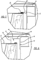
Fig. 1 is a side cross-sectional view of an exemplary combination washer/dryer unit; -
Fig. 2 is an enlarged side cross-sectional view of the combination washer/dryer unit shown inFig. 1 ; -
Fig. 3 is a side cross-sectional view of an exemplary seal according to a first embodiment of the present disclosure, which closes a gap between a drum and a tub of the combination washer/dryer unit; -
Fig. 4 is a side cross-sectional view of a second embodiment of the seal; -
Fig. 5 is a side cross-sectional view of a third embodiment of the seal; -
Fig. 6 is a side cross-sectional view of a fourth embodiment of the seal; -
Fig. 7 is a side cross-sectional view of the gap between the drum and the tub with the seal ofFig. 4 positioned on the drum; -
Fig. 8 is a side cross-sectional view of the gap between the drum and the tub with an exemplary seal according to a fifth embodiment where the seal is positioned on the tub; -
Fig. 9 is side cross-sectional view of a sixth embodiment of the seal where the seal is mounted to a flange on the tub; -
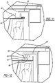
Figs. 10A-10C are side cross-sectional views of various seals that may be installed on the flange shown inFig. 9 ; -
Fig. 11 is a side cross-sectional view of a seventh embodiment of the seal; and -
Fig. 12 is a side cross-sectional view of an eighth embodiment of the seal. -
Figure 1 illustrates a combination washer/dryer unit, which includes tub/drum assembly designated with thereference numeral 10. The tub/drum assembly 10 is positioned inside of a housing of the combination washer/dryer unit. The tub/drum assembly 10 includes adrum 12 and atub 14. Thedrum 12 is rotatably positioned within thetub 14. With additional reference toFigure 2 , anaxial gap 16 is formed between thedrum 12 and thetub 14. Thedrum 12 includes arear end 18, which may include a crimped flange connecting abase 17 of thedrum 12 with acylindrical wall 19 of thedrum 12. - With additional reference to
Figure 3 , aseal 20 is positioned on therear end 18 of thedrum 12, around the crimped flange, to close theaxial gap 16 between thetub 14 anddrum 12. Theseal 20 controls the amount of airflow that is permitted to pass/flow around thedrum 12, which enables a maximum amount of air to enter into thedrum 12 during the drying cycle. - The
seal 20 includes aring 22 that is positioned around and secured to thedrum 12. Theseal 20 also includes aretention portion 24 that wraps around the crimped flange at therear end 18 of thedrum 12 to enhance the retention of theseal 20 onto thedrum 12. Theretention portion 24 includes apocket 26 that enables the crimped flange at therear end 18 of thedrum 12 to be positioned inside of theretention portion 24. - The
seal 20 also includes anarm 28 that extends from thering 22 into theaxial gap 16 between thedrum 12 and thetub 14. Thearm 28 includes a mass 30 at its terminal end to enable movement of thearm 28 andmass 30 during rotation of thedrum 12. During the washing cycle, thedrum 12 may rotate at 400 RPM or greater. During this time, thearm 28 unfolds or deflects to enable theaxial gap 16 to become larger between thedrum 12 andtub 14. This enables the air and water between thedrum 12 andtub 14 to exit. - During the spin cycle and drying cycle, the
drum 12 spins at about 50-55 RPM. During this rotation speed, thearm 28 does not unfold or deflect and enables theaxial gap 16 to become smaller between thedrum 12 and thetub 14. Thus, during the drying cycle, airflow is forced into thedrum 12 to enhance the drying of the clothes within thedrum 12. - Due to the extension, deflection or unfolding of the
arm 28 andmass 30 during washing cycles, thearm 28 ormass 30 may contact thetub 14. As shown inFig. 7 , a coating orpart 32 may be positioned onto thetub 14 to prevent the seal from being damaged or torn during rotation of thedrum 12. The coating orpart 32 is generally manufactured from a composite material and is generally positioned on thetub 14 at a location where theseal 20 rubs against thetub 14. - Turning to
Figs. 4-6 ,additional seals 20 are illustrated. Thus, the same numerals are utilized to identify the same parts. InFig. 4 , theseal 20 includes aring 22 with aretention portion 24. The arm 28' extends in a downward fashion. Themass 30 is at the terminal end of the arm 28'. - In
Figs. 5 and 6 , the arm 28' includes achamber 40 that is configured to receive a fluid inFig. 5 and a metal mass inFig. 6 . Thus, themass 30 can be altered to provide the desired movement of the arm 28' andmass 30 during the rotation of thedrum 12. Also, awiper 42 may extend from themass 30 toward thetub 14. - Turning to
Fig. 8 , an additional embodiment of the disclosure is shown. InFig. 8 , thedrum 12 and thetub 14 are illustrated with aradial gap 50 between thedrum 12 and thetub 14. The size of theradial gap 50 controls / limits the amount of air that exits around thedrum 12. - A
seal 60 includes aring 62 that is secured to thetub 14. Theseal 60 also includes anarm 64 that extends from thering 62 into theradial gap 50. Thearm 64 may include alip 66 that extends transverse to thearm 64, toward thedrum 12, to provide an additional member to control / limit the airflow through theradial gap 50. Theseal 60 may be made of a metal or resin material that provides a desired amount of rigidity. This rigidity enables theseal 60 to provide a high resistance in the airflow path while maintaining a smallradial gap 50 between thedrum 12 and thearm 64. - Turning to
Figs. 9 and 10A , an additional embodiment is shown. Here, thearm 64 does not include thelip 66. This enables aseal 70 to be secured to thearm 64. Theseal 70 generally includes aretention portion 72 to secure theseal 70 to thearm 64. Also, theseal 70 includes awiper 74 that extends from theretention portion 72 toward thedrum 12. Thewiper 74 is positioned at a desired distance away from thedrum 12 so that a small radial gap is formed between thedrum 12 and seal 70 to control / limit the airflow passing through the radial gap between thedrum 12 and theseal 70. -
Fig. 10B illustrates anotherseal 70 that includes acurved wiper 76. It is positioned to form a radial gap between thedrum 12 and thesealing wiper 76.Fig. 10C illustrates aseal 70 with abulb 78. Thebulb 78 extends toward thedrum 12 to form a constant radial gap between thebulb 78 and thedrum 12. - Turning to
Fig. 11 , an additional embodiment is illustrated. Here, thedrum 12 includes agroove seal 80 positioned peripherally about an external surface of thedrum 12. Thegroove seal 80 may have one or two extendingmembers 82 that provide a labyrinth seal when theseal 70 is attached to thearm 64. Thus, the gap between thetub 12 and drum 14 can be further modified to control / limit airflow through the gap between thedrum 12 andtub 14. -
Fig. 12 shows an additional embodiment of thegroove seal 80. Here, thearm 64 includesmultiple wipers 90 while thegroove seal 80 includesmultiple grooves wipers 90 from thearm 64. Thus, this provides a labyrinth seal to control the airflow through the gap between thedrum 12 and thetub 14.
Claims (15)
- A tub/drum assembly (10) for a combination washer/dryer unit, comprising:a tub (14);a drum (12) rotatably positioned within the tub (14), the drum (12) including a cylindrical wall (19) that is connected to a base (17) at a rear end (18) of the drum (12) and the drum (12) is spaced from the tub (14) such that a gap (16, 50) is formed between the drum (12) and the tub (14) through which air can flow instead of entering the drum (12) during a drying cycle; anda seal (20, 60, 70) positioned near the cylindrical wall (19) at the rear end (18) of the drum (12) that extends at least partially across the gap (16, 50) between the drum (12) and the tub (14) to limit the amount of airflow through the gap (16, 50) between the drum (12) and the tub (14) during the drying cycle.
- The tub/drum assembly (10) according to Claim 1, wherein the seal (20) is secured to the rear end (18) of the drum (12).
- The tub/drum assembly (10) according to Claim 1 or 2, wherein the seal (20) includes a ring (22) that is positioned around and secured to the drum (12), and an arm (28, 28') that extends from the ring (22) into the gap (16) between the tub (14) and the drum (12).
- The tub/drum assembly (10) according to Claim 3, wherein the seal (20) includes a mass (30) at a terminal end of the arm (28, 28'), the mass (30) enabling the arm (28, 28') of the seal (20) to deflect or extend at high rotational speeds of the drum (12) to increase the gap (16) between the tub (14) and the drum (12).
- The tub/drum assembly (10) according to Claim 4, wherein the terminal end of the arm (28, 28') includes a chamber (40) for retaining the mass (30) inside the chamber (40).
- The tub/drum assembly (10) according to Claim 5, wherein the mass (30) received in the chamber (40) is a fluid.
- The tub/drum assembly (10) according to Claim 5, wherein the mass (30) received in the chamber (40) is metal.
- The seal (20) for a tub/drum assembly (10) according to any one of the preceding Claims, wherein the rear end (18) of the drum (12) includes a crimped flange where the cylindrical wall (19) of the drum (12) is connected to the base (17) of the drum (12) and wherein the seal (20) includes a pocket (26) that receives the crimped flange to secure the seal (20) to the rear end (18) of the drum (12).
- The tub/drum assembly (10) according to one of Claims 2-8, further comprising a composite material (32) on the tub (14), wherein the seal (20) is positioned to make contact with the composite material (32) and the composite material (32) is configured to prevent seal damage.
- The tub/drum assembly (10) according to Claim 1, wherein the seal (60, 70) is secured to the tub (14).
- The tub/drum assembly (10) according to Claim 10, wherein the seal (60, 70) includes a lip (66) or wiper (74) that extends towards the drum (12).
- The tub/drum assembly (10) according to Claim 11, further comprising a groove seal (80) secured to the rear end (18) of the drum (12), wherein the groove seal (80) includes at least one extending member (82) that cooperates with the lip (66) or wiper (74) to provide a labyrinth seal that limits the airflow through the gap (50) between the drum (12) and the tub (14).
- The tub/drum assembly (10) according to Claim 12, wherein the groove seal (80) includes two extending members (82) and the lip (66) or wiper (74) is received between the two extending members (82).
- The tub/drum assembly (10) according to Claim 10, wherein the seal (60) that is secured to the tub (14) includes multiple wipers (90) and wherein a groove seal (80) is secured to the cylindrical wall (19) near the rear end (18) of the drum (12) and wherein the groove seal (80) includes multiple grooves (94, 96) that receive the multiple wipers (90) to provide a labyrinth seal that limits the airflow through the gap (50) between the drum (12) and the tub (14).
- The tub/drum assembly (10) according to any one of Claims 10-14, wherein the seal (60) includes a ring (62) that is secured to the tub (14) and an arm (64) that extends from the ring (62) into the gap (50) between the drum (12) and the tub (14).
Applications Claiming Priority (1)
| Application Number | Priority Date | Filing Date | Title |
|---|---|---|---|
| US17/357,309 US20220411986A1 (en) | 2021-06-24 | 2021-06-24 | Drum Bypass Control |
Publications (1)
| Publication Number | Publication Date |
|---|---|
| EP4112797A1 true EP4112797A1 (en) | 2023-01-04 |
Family
ID=81940588
Family Applications (1)
| Application Number | Title | Priority Date | Filing Date |
|---|---|---|---|
| EP22177103.3A Withdrawn EP4112797A1 (en) | 2021-06-24 | 2022-06-02 | Drum bypass control |
Country Status (3)
| Country | Link |
|---|---|
| US (1) | US20220411986A1 (en) |
| EP (1) | EP4112797A1 (en) |
| CN (1) | CN115522360A (en) |
Citations (4)
| Publication number | Priority date | Publication date | Assignee | Title |
|---|---|---|---|---|
| KR20050037187A (en) * | 2003-10-17 | 2005-04-21 | 엘지전자 주식회사 | Clothes dryer |
| WO2009041345A1 (en) * | 2007-09-26 | 2009-04-02 | Sanyo Electric Co., Ltd. | Dryer |
| WO2014181493A1 (en) * | 2013-05-07 | 2014-11-13 | パナソニックIpマネジメント株式会社 | Washing and drying machine |
| EP3995615A1 (en) * | 2020-11-10 | 2022-05-11 | Whirlpool Corporation | Maximizing the dry rate of clothes tumbling combination washer/dryer with a seal |
Family Cites Families (1)
| Publication number | Priority date | Publication date | Assignee | Title |
|---|---|---|---|---|
| KR20180055420A (en) * | 2016-11-17 | 2018-05-25 | 엘지전자 주식회사 | Laundry treating machine |
-
2021
- 2021-06-24 US US17/357,309 patent/US20220411986A1/en not_active Abandoned
-
2022
- 2022-06-02 EP EP22177103.3A patent/EP4112797A1/en not_active Withdrawn
- 2022-06-22 CN CN202210710058.XA patent/CN115522360A/en active Pending
Patent Citations (4)
| Publication number | Priority date | Publication date | Assignee | Title |
|---|---|---|---|---|
| KR20050037187A (en) * | 2003-10-17 | 2005-04-21 | 엘지전자 주식회사 | Clothes dryer |
| WO2009041345A1 (en) * | 2007-09-26 | 2009-04-02 | Sanyo Electric Co., Ltd. | Dryer |
| WO2014181493A1 (en) * | 2013-05-07 | 2014-11-13 | パナソニックIpマネジメント株式会社 | Washing and drying machine |
| EP3995615A1 (en) * | 2020-11-10 | 2022-05-11 | Whirlpool Corporation | Maximizing the dry rate of clothes tumbling combination washer/dryer with a seal |
Also Published As
| Publication number | Publication date |
|---|---|
| CN115522360A (en) | 2022-12-27 |
| US20220411986A1 (en) | 2022-12-29 |
Similar Documents
| Publication | Publication Date | Title |
|---|---|---|
| CA2267744C (en) | Seal arrangement between inner and outer tubs of a horizontal axis washing machine | |
| EP0639339A1 (en) | Improvements relating to hairdrying apparatus | |
| US11795601B2 (en) | Maximizing the dry rate of clothes tumbling combination washer/dryer with a seal | |
| US8528223B2 (en) | Laundry deflector device for a household appliance for attending to items of laundry, and such a household appliance | |
| JP6212701B2 (en) | Washing and drying machine | |
| EP2489777A1 (en) | Clothing dryer and washer dryer | |
| US4974339A (en) | Clothes dryer | |
| US20220411986A1 (en) | Drum Bypass Control | |
| EP4023805B1 (en) | Controlling process air bypass around the drum in combo wash-dry system | |
| KR101141641B1 (en) | structure for condensing duct of drum type washing machine with laundry drying function | |
| CN111979693A (en) | Device for washing and drying objects and method for operating such a device | |
| KR20050108117A (en) | Apparatus for sealing drum in clothing dryer | |
| US20130340486A1 (en) | Water-conducting household appliance having a rotatable component | |
| US11053632B2 (en) | Dryer appliance and impeller housing | |
| JP4945154B2 (en) | Washing and drying machine | |
| CN220890582U (en) | Drying fan and washing drier | |
| EP4495314B1 (en) | Tub and drum type washer dryer | |
| JP2012217458A (en) | Drum-type washing and drying machine | |
| KR100499511B1 (en) | Duct for Drum Type Washer | |
| US12590394B2 (en) | Air bypass seal with backer for improved drying performance in a combination washer/dryer | |
| EP3754093A1 (en) | Fan and washing machine having same | |
| CN213681406U (en) | Drying fan of washing machine | |
| EP0364080A1 (en) | Laundry dryers | |
| JP6538377B2 (en) | Washing machine | |
| CN216919769U (en) | Noise reduction structure, fan and clothing treatment facility |
Legal Events
| Date | Code | Title | Description |
|---|---|---|---|
| PUAI | Public reference made under article 153(3) epc to a published international application that has entered the european phase |
Free format text: ORIGINAL CODE: 0009012 |
|
| STAA | Information on the status of an ep patent application or granted ep patent |
Free format text: STATUS: THE APPLICATION HAS BEEN PUBLISHED |
|
| AK | Designated contracting states |
Kind code of ref document: A1 Designated state(s): AL AT BE BG CH CY CZ DE DK EE ES FI FR GB GR HR HU IE IS IT LI LT LU LV MC MK MT NL NO PL PT RO RS SE SI SK SM TR |
|
| RAP3 | Party data changed (applicant data changed or rights of an application transferred) |
Owner name: WHIRLPOOL CORPORATION |
|
| STAA | Information on the status of an ep patent application or granted ep patent |
Free format text: STATUS: REQUEST FOR EXAMINATION WAS MADE |
|
| 17P | Request for examination filed |
Effective date: 20230704 |
|
| RBV | Designated contracting states (corrected) |
Designated state(s): AL AT BE BG CH CY CZ DE DK EE ES FI FR GB GR HR HU IE IS IT LI LT LU LV MC MK MT NL NO PL PT RO RS SE SI SK SM TR |
|
| P01 | Opt-out of the competence of the unified patent court (upc) registered |
Effective date: 20230721 |
|
| GRAP | Despatch of communication of intention to grant a patent |
Free format text: ORIGINAL CODE: EPIDOSNIGR1 |
|
| STAA | Information on the status of an ep patent application or granted ep patent |
Free format text: STATUS: GRANT OF PATENT IS INTENDED |
|
| INTG | Intention to grant announced |
Effective date: 20240220 |
|
| GRAS | Grant fee paid |
Free format text: ORIGINAL CODE: EPIDOSNIGR3 |
|
| STAA | Information on the status of an ep patent application or granted ep patent |
Free format text: STATUS: THE APPLICATION IS DEEMED TO BE WITHDRAWN |
|
| 18D | Application deemed to be withdrawn |
Effective date: 20250103 |