EP4112790A1 - Manufacturing method of processed yarn and yarn processor - Google Patents
Manufacturing method of processed yarn and yarn processor Download PDFInfo
- Publication number
- EP4112790A1 EP4112790A1 EP22175113.4A EP22175113A EP4112790A1 EP 4112790 A1 EP4112790 A1 EP 4112790A1 EP 22175113 A EP22175113 A EP 22175113A EP 4112790 A1 EP4112790 A1 EP 4112790A1
- Authority
- EP
- European Patent Office
- Prior art keywords
- yarn
- heater
- contact surface
- degrees centigrade
- temperature
- Prior art date
- Legal status (The legal status is an assumption and is not a legal conclusion. Google has not performed a legal analysis and makes no representation as to the accuracy of the status listed.)
- Pending
Links
- 238000004519 manufacturing process Methods 0.000 title claims abstract description 27
- 238000010438 heat treatment Methods 0.000 claims abstract description 118
- 229920002994 synthetic fiber Polymers 0.000 claims abstract description 6
- 239000012209 synthetic fiber Substances 0.000 claims abstract description 6
- 239000000463 material Substances 0.000 claims description 20
- 229920000728 polyester Polymers 0.000 claims description 13
- 229920002292 Nylon 6 Polymers 0.000 claims description 10
- 229920002302 Nylon 6,6 Polymers 0.000 claims description 10
- 230000004927 fusion Effects 0.000 abstract description 34
- 238000004804 winding Methods 0.000 description 27
- MHCVCKDNQYMGEX-UHFFFAOYSA-N 1,1'-biphenyl;phenoxybenzene Chemical compound C1=CC=CC=C1C1=CC=CC=C1.C=1C=CC=CC=1OC1=CC=CC=C1 MHCVCKDNQYMGEX-UHFFFAOYSA-N 0.000 description 17
- 230000008602 contraction Effects 0.000 description 13
- 238000011144 upstream manufacturing Methods 0.000 description 4
- 238000011156 evaluation Methods 0.000 description 3
- 238000002844 melting Methods 0.000 description 3
- 230000008018 melting Effects 0.000 description 3
- 238000000034 method Methods 0.000 description 3
- 238000003672 processing method Methods 0.000 description 3
- 238000010586 diagram Methods 0.000 description 2
- 239000002184 metal Substances 0.000 description 2
- 229910052751 metal Inorganic materials 0.000 description 2
- 230000005855 radiation Effects 0.000 description 2
- 229910000928 Yellow copper Inorganic materials 0.000 description 1
- 230000003247 decreasing effect Effects 0.000 description 1
- 238000001514 detection method Methods 0.000 description 1
- 230000005484 gravity Effects 0.000 description 1
- 239000012770 industrial material Substances 0.000 description 1
- 239000000155 melt Substances 0.000 description 1
- 239000007769 metal material Substances 0.000 description 1
- 238000012986 modification Methods 0.000 description 1
- 230000004048 modification Effects 0.000 description 1
- 230000000644 propagated effect Effects 0.000 description 1
Images
Classifications
-
- D—TEXTILES; PAPER
- D02—YARNS; MECHANICAL FINISHING OF YARNS OR ROPES; WARPING OR BEAMING
- D02G—CRIMPING OR CURLING FIBRES, FILAMENTS, THREADS, OR YARNS; YARNS OR THREADS
- D02G1/00—Producing crimped or curled fibres, filaments, yarns, or threads, giving them latent characteristics
- D02G1/02—Producing crimped or curled fibres, filaments, yarns, or threads, giving them latent characteristics by twisting, fixing the twist and backtwisting, i.e. by imparting false twist
- D02G1/0206—Producing crimped or curled fibres, filaments, yarns, or threads, giving them latent characteristics by twisting, fixing the twist and backtwisting, i.e. by imparting false twist by false-twisting
- D02G1/0266—Producing crimped or curled fibres, filaments, yarns, or threads, giving them latent characteristics by twisting, fixing the twist and backtwisting, i.e. by imparting false twist by false-twisting false-twisting machines
-
- D—TEXTILES; PAPER
- D02—YARNS; MECHANICAL FINISHING OF YARNS OR ROPES; WARPING OR BEAMING
- D02J—FINISHING OR DRESSING OF FILAMENTS, YARNS, THREADS, CORDS, ROPES OR THE LIKE
- D02J13/00—Heating or cooling the yarn, thread, cord, rope, or the like, not specific to any one of the processes provided for in this subclass
- D02J13/003—Heating or cooling the yarn, thread, cord, rope, or the like, not specific to any one of the processes provided for in this subclass by contact with at least one stationary surface, e.g. a plate
-
- D—TEXTILES; PAPER
- D02—YARNS; MECHANICAL FINISHING OF YARNS OR ROPES; WARPING OR BEAMING
- D02G—CRIMPING OR CURLING FIBRES, FILAMENTS, THREADS, OR YARNS; YARNS OR THREADS
- D02G1/00—Producing crimped or curled fibres, filaments, yarns, or threads, giving them latent characteristics
- D02G1/02—Producing crimped or curled fibres, filaments, yarns, or threads, giving them latent characteristics by twisting, fixing the twist and backtwisting, i.e. by imparting false twist
- D02G1/0206—Producing crimped or curled fibres, filaments, yarns, or threads, giving them latent characteristics by twisting, fixing the twist and backtwisting, i.e. by imparting false twist by false-twisting
Definitions
- the present invention relates to (i) a method of manufacturing processed yarns and (ii) a yarn processor.
- Patent Literature 1 Japanese Laid-Open Patent Publication No. 2005-68573 discloses a heater (primary heater in Patent Literature 1) with DOWTHERM (Registered Trademark of Dow Inc.) which is a heating medium.
- DOWTHERM Registered Trademark of Dow Inc.
- a contact plate contact member with which a yarn makes contact is heated to a predetermined processing temperature by the heating medium.
- the yarn is heated to the processing temperature (in a contact manner).
- Patent Literature 2 Japanese Laid-Open Patent Publication No.
- Patent Literature 2 Japanese Laid-Open Patent Publication No. 2002-194631 discloses a means for switching a way of heating between the contact manner and the contactless manner in a heater in which a sheathed heater is a heat source.
- a heating temperature (the set temperature of a contact member) to be low (e.g., 225 degrees centigrade or less in Patent Literature 3).
- a heating temperature (the set temperature in a yarn running space) to be high (e.g., 420 degrees centigrade or more in Patent Literature 3).
- the present inventors have opinions about the reasons of these arrangements.
- the heating temperature is within one range (hereinafter, this range will be referred to as the middle range) and a yarn cannot properly run because of yarn breakage, the yarn disadvantageously melts in a heater and adheres to the heater (i.e., results of the fusion).
- the heater In order to remove the adhered matters, the heater needs to be stopped for a long time. When each set temperature is sufficiently high, the yarn is easily sublimed at a time of yarn breakage. As a result, the fusion between the yarn and the heater is avoided. Therefore, the heating temperature has been set to be lower than the middle range in the contact manner and to be higher than the middle range in the contactless manner. Meanwhile, a yarn processing method and a yarn processor with a high heating efficiency are required.
- An object of the present invention is to increase, when a yarn is heated and processed in a heater, a heating efficiency while avoiding risk of fusion in yarn breakage.
- a manufacturing method of processed yarns includes a step of heating a running yarn, which is made of synthetic fibers, by means of a heater, the heater including a heat source and a heating unit which is heated by the heat source, the heating unit including a contact surface extending at least in a predetermined extending direction, the running yarn making contact with the contact surface, the contact surface being oriented at least downward, the heater being provided so that an inclination angle of the contact surface with respect to a horizontal direction is within a range of -60 to 60 degrees in a cross section parallel to both a vertical direction and the extending direction, and the yarn running and making contact with the contact surface, while the temperature of the contact surface is set at a predetermined temperature which is not less than 230 degrees centigrade and not more than 350 degrees centigrade.
- a temperature range of 230 to 350 degrees centigrade is referred to as a middle range.
- a heating temperature of the contact surface is not more than 350 degrees centigrade, there is risk of fusion of the yarn.
- the present inventors considered that it would be possible to further efficiently heat the yarn by, while avoiding the fusion, using a contact manner and setting the heating temperature within the middle range. That is, the heating temperature is able to be set to be higher in this case as compared to cases where a traditional contact manner is used. It is therefore possible to increase a heating efficiency. Even when the heating temperature of the heater is lower than that of a traditional heater with a contactless manner, the yarn is able to be efficiently heated by the contact surface (i.e., it is possible to increase the heating efficiency).
- the yarn in a regular state (i.e., state in which the yarn properly runs), even when the temperature (heating temperature) of the contact surface is at the predetermined temperature within the middle range, the yarn is heated to an appropriate processing temperature (i.e., the fusion is avoided) by suitably setting the type, brand (thickness), and running speed of the yarn and the heating temperature.
- the contact surface is oriented at least downward, and the inclination angle of the contact surface with respect to the horizontal direction is within the range of -60 to 60 degrees. (The specific definition of the inclination angle will be described later in the embodiment.)
- the manufacturing method of the first aspect is arranged such that a material of the yarn is polyester and the predetermined temperature is not less than 250 degrees centigrade and not more than 350 degrees centigrade.
- polyester when the heating temperature is not less than 250 degrees centigrade, the fusion is highly likely to occur. This aspect of the invention is especially effective to avoid the fusion at this heating temperature.
- the manufacturing method of the first aspect is arranged such that a material of the yarn is nylon 6 and the predetermined temperature is not less than 230 degrees centigrade and not more than 350 degrees centigrade.
- the manufacturing method of the first aspect is arranged such that a material of the yarn is nylon 66, and the predetermined temperature is not less than 260 degrees centigrade and not more than 350 degrees centigrade.
- nylon 66 when the heating temperature is not less than 260 degrees centigrade, the fusion is highly likely to occur. This aspect of the invention is especially effective to avoid the fusion at this heating temperature.
- the manufacturing method of any one of the first to fourth aspects is arranged such that the predetermined temperature is not more than 320 degrees centigrade.
- the fusion may be likely to occur in accordance with conditions such as the type and/or thickness of the yarn and the running speed of the yarn. According to this aspect, the fusion is further reliably avoided by setting the heating temperature to be lower than 320 degrees centigrade.
- the manufacturing method of any one of the first to the fifth aspects is arranged such that an electric heater is used as the heat source.
- a heat source configured to heat the contact surface by means of a heating medium and a heat source configured to heat the contact surface by means of Joule heat generated by an electric heater. Because the heat source with the heating medium typically has the limit of increase in temperature of the heating medium, it is difficult to increase the temperature of the contact surface. In this aspect of the invention, it is possible to easily increase the temperature of the contact surface by using the electric heater.
- the manufacturing method of the sixth aspect is arranged such that the heater in the extending direction is not less than 0.4 m and not more than 1.6 m in length.
- a yarn processor includes a heater configured to heat a running yarn made of synthetic fibers, the heater including a heat source, a heating unit which is heated by the heat source, and a controller programmed to control the heat source, the heating unit including a contact surface extending at least in a predetermined extending direction, the running yarn making contact with the contact surface, the contact surface being oriented at least downward, the heater being provided so that an inclination angle of the contact surface with respect to a horizontal direction is within a range of -60 to 60 degrees in a cross section parallel to both a vertical direction and the extending direction, and when the yarn runs while making contact with the contact surface, the controller controlling the heat source so that the temperature of the contact surface is set at a predetermined temperature which is not less than 230 degrees centigrade and not more than 350 degrees centigrade.
- the yarn processor of the eighth aspect is arranged such that a material of the yarn is polyester and the predetermined temperature is not less than 250 degrees centigrade and not more than 350 degrees centigrade.
- the yarn processor of the eighth aspect is arranged such that a material of the yarn is nylon 6 and the predetermined temperature is not less than 230 degrees centigrade and not more than 350 degrees centigrade.
- the yarn processor of the eighth aspect is arranged such that a material of the yarn is nylon 66 and the predetermined temperature is not less than 260 degrees centigrade and not more than 350 degrees centigrade.
- the yarn processor of any one of the eighth to eleventh aspects is arranged such that the heat source includes an electric heater.
- the yarn processor of the twelfth aspect is arranged such that the heater in the extending direction is not less than 0.4 m and not more than 1.6 m in length.
- a vertical direction to the sheet of FIG. 1 is defined as a base longitudinal direction
- a left-right direction to the sheet of FIG. 1 is defined as a base width direction
- a direction orthogonal to the base longitudinal direction and the base width direction is defined as an up-down direction (vertical direction) in which the gravity acts.
- the base longitudinal direction and the base width direction are substantially in parallel to the horizontal direction.
- FIG. 1 is a profile of the false-twist texturing machine 1.
- FIG. 2 is a schematic diagram of the false-twist texturing machine 1, expanded along paths of yarns Y (i.e., yarn paths).
- the false-twist texturing machine 1 is able to false-twist the yarns Y made of synthetic fibers (such as polyester). Each yarn Y is, for example, a multi-filament yarn made of plural filaments. Alternatively, each yarn Y may be made of one filament.
- the false-twist texturing machine 1 includes a yarn supplying unit 2, a processing unit 3, and a winding unit 4.
- the yarn supplying unit 2 is able to supply the yarns Y.
- the processing unit 3 is configured to pull out the yarns Y from the yarn supplying unit 2 and to false-twist the yarns Y.
- the winding unit 4 is configured to wind the yarns Y which has been processed by the processing unit 3 onto winding bobbins Bw.
- the base longitudinal direction is a direction orthogonal to a yarn running surface (i.e., sheet of FIG. 1 ) on which yarn paths from the yarn supplying unit 2 to the winding unit 4 through the processing unit 3 are provided.
- the yarn supplying unit 2 includes a creel stand 7 retaining yarn supply packages Ps, and supplies the yarns Y to the processing unit 3.
- the processing unit 3 is configured to pull out the yarns Y from the yarn supplying unit 2 and to process the yarns Y.
- the following members are placed in this order from the upstream side in a yarn running direction in which the yarns Y run: first feed rollers 11; twist-stopping guides 12; first heaters 13 (heaters of the present invention); coolers 14; false-twisting devices 15; second feed rollers 16; interlacing devices 17; third feed rollers 18; a second heater 19; and fourth feed rollers 20.
- the winding unit 4 includes plural winding devices 21. Each winding device 21 winds a corresponding yarn Y which has been false-twisted by the processing unit 3 onto a winding bobbin Bw and forms a wound package Pw.
- the false-twist texturing machine 1 includes a main frame 8 and a winding base 9 that are spaced apart from each other in the base width direction.
- the main frame 8 and the winding base 9 are substantially identical in length in the base longitudinal direction.
- the main frame 8 and the winding base 9 oppose each other in the base width direction.
- the false-twist texturing machine 1 includes units which are termed spans, each of which includes a pair of the main frame 8 and the winding base 9. In one span, each device is placed so that the yarns Y running while being aligned in the base longitudinal direction can be simultaneously false-twisted.
- the spans are placed in a left-right symmetrical manner to the sheet, with a center line C of the base width direction of the main frame 8 being set as a symmetry axis (i.e., main frame 8 is shared between the left span and the right span).
- the spans are aligned in the base longitudinal direction.
- Each first feed roller 11 is configured to unwind one yarn Y from one yarn supply package Ps attached to the yarn supplying unit 2, and to feed the yarn Y to a corresponding first heater 13. As shown in FIG. 2 , for example, each first feed roller 11 is configured to feed one yarn Y to a corresponding first heater 13. Alternatively, each first feed roller 11 may be able to feed adjacent yarns Y to the downstream side in the yarn running direction.
- Each twist-stopping guide 12 is provided to prevent twist of the yarn Y from being propagated to the upstream side of the twist-stopping guide 12 in the yarn running direction. The twist of the yarn Y is formed by a corresponding false-twisting device 15.
- Each first heater 13 is configured to heat the yarns Y supplied from some first feed rollers 11 to a predetermined processing temperature. As shown in FIG. 2 , for example, each first heater 13 is able to heat two yarns Y. Each first heater 13 will be detailed later.
- Each cooler 14 is configured to cool one of the yarns Y heated by the first heater 13. As shown in FIG. 2 , for example, each cooler 14 is configured to cool one yarn Y. Alternatively, the cooler 14 may be able to simultaneously cool plural yarns Y.
- Each false-twisting device 15 is provided downstream of a corresponding cooler 14 in the yarn running direction, and configured to twist the yarn Y. Each false-twisting device 15 is, for example, a so-called disc-friction false-twisting device. However, the disclosure is not limited to this.
- Each second feed roller 16 is configured to feed the yarn Y processed by the false-twisting device 15 to a corresponding interlacing device 17.
- the conveyance speed of conveying the yarn Y by each second feed roller 16 is higher than the conveyance speed of conveying the yarn Y by each first feed roller 11. With this arrangement, the yarn Y is therefore drawn and false-twisted between each first feed roller 11 and each second feed roller 16.
- Each interlacing device 17 is configured to interlace the yarn Y.
- Each interlacing device 17 has, for example, a known interlace nozzle configured to interlace the yarn Y by means of an airflow.
- Each third feed roller 18 is configured to feed the yarn Y running downstream of a corresponding interlacing device 17 in the yarn running direction, to the second heater 19. As shown in FIG. 2 , for example, each third feed roller 18 is configured to feed one yarn Y to the second heater 19. Alternatively, each third feed roller 18 may be able to feed adjacent yarns Y to the downstream side in the yarn running direction. The conveyance speed of conveying the yarn Y by each third feed roller 18 is lower than the conveyance speed of conveying the yarn Y by each second feed roller 16. The yarn Y is therefore relaxed between each second feed roller 16 and each third feed roller 18. The second heater 19 is configured to heat the yarns Y fed from some third feed rollers 18.
- the second heater 19 extends along the vertical direction, and one second heater 19 is provided in one span.
- Each fourth feed roller 20 is configured to feed one of the yarns Y heated by the second heater 19 to a corresponding winding device 21. As shown in FIG. 2 , for example, each fourth feed roller 20 is able to feed one yarn Y to the winding device 21. Alternatively, each fourth feed roller 20 may be able to feed adjacent yarns Y to the downstream side in the yarn running direction. The conveyance speed of conveying the yarn Y by each fourth feed roller 20 is lower than the conveyance speed of conveying the yarn Y by each third feed roller 18. The yarn Y is therefore relaxed between each third feed roller 18 and each fourth feed roller 20.
- each of the yarns Y drawn between the first feed rollers 11 and the second feed rollers 16 is twisted by a corresponding false-twisting device 15.
- the twist formed by the false-twisting device 15 propagates to a corresponding twist-stopping guide 12, but does not propagate to the upstream side of the twist-stopping guide 12 in the yarn running direction.
- the yarn Y which is twisted and drawn is heated by a corresponding first heater 13 and thermally set. After that, the yarn Y is cooled by a corresponding cooler 14.
- the yarn Y is untwisted on the downstream side of a corresponding false-twisting device 15 in the yarn running direction.
- the yarn Y is maintained to be wavy in shape on account of the thermal setting described above (i.e., the crimp contraction of the yarn Y is maintained).
- the false-twisted yarn Y is interlaced by a corresponding interlacing device 17 while being relaxed between a corresponding second feed roller 16 and a corresponding third feed roller 18. After that, the yarn Y is guided toward the downstream side in the yarn running direction. Subsequently, the yarn Y is thermally set by the second heater 19 while being relaxed between the third feed roller 18 and a corresponding fourth feed roller 20. Finally, the yarn Y which is fed by the fourth feed roller 20 is wound by a corresponding winding device 21.
- the winding unit 4 includes the winding devices 21. Each winding device 21 is able to wind one yarn Y onto one winding bobbin Bw.
- the winding device 21 includes a fulcrum guide 41, a traverse unit 42, and a cradle 43.
- the fulcrum guide 41 is a guide which is a fulcrum when the yarn Y is traversed.
- the traverse unit 42 is able to traverse the yarn Y by means of a traverse guide 45.
- the cradle 43 is configured to rotatably support the winding bobbin Bw.
- a contact roller 46 is provided in the vicinity of the cradle 43.
- the contact roller 46 is configured to apply a contact pressure by making contact with the surface of one wound package Pw.
- the yarn Y which is fed by the fourth feed roller 20 described above is wound onto the winding bobbin Bw by the winding device 21, and forms the wound package Pw.
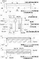
- FIG. 3(a) illustrates one first heater 13 which is viewed in the base longitudinal direction so that a direction in which the first heater 13 extends (extending direction described later) is the left-right direction of the sheet of FIG. 3(a).
- FIG. 3(b) is a cross section taken along a line Ab-Ab in FIG. 3(a).
- FIG. 3(c) is a cross section taken along a line Ac-Ac in FIG. 3(b).
- FIG. 3(d) is a cross section taken along a line Ad-Ad in FIG. 3(b) .
- a direction orthogonal to both the base longitudinal direction and the extending direction is defined as a height direction (see FIG.
- the left side of the sheet is defined as one side in the extending direction
- the right side of the sheet is defined as the other side in the extending direction.
- the one side in the extending direction may be, for example, on the upstream side in the yarn running direction.
- the disclosure is not limited to this.
- the upper side of the sheet is defined as one side in the height direction
- the lower side of the sheet is defined as the other side in the height direction.
- the first heater 13 is configured to heat at least one running yarn Y.
- the first heater 13 is able to heat, for example, two yarns Y (yarn Ya and Yb; see FIG. 3(b) ).
- the first heater 13 extends in a predetermined extending direction orthogonal to the base longitudinal direction (see FIG. 3(a) , etc.).
- the length of the first heater 13 in the extending direction is preferably not less than 0.4 m and not more than 1.6 m.
- the length of the first heater 13 in the extending direction may be, for example, not less than 1.0 m and not more than 1.5 m.
- the first heater 13 with an appropriate length in the extending direction is preferably selected in accordance with conditions such as the type of the yarns, the thickness of the yarns, and the yarn running speed.
- the first heater 13 includes a heat source 51 and a heating unit 52.
- the first heater 13 is configured to simultaneously heat the yarns Ya and Yb by causing the running yarns Ya and Yb to make contact with the heating unit 52 which is heated by the heat source 51.
- the heat source 51 is, for example, a known sheathed heater (electric heater).
- the sheathed heater includes a heating wire (such as a coil) and a pipe surrounding the heating wire.
- the sheathed heater is configured to generate Joule heat when an electrical current flows in the heating wire.
- the heat source 51 extends along the extending direction (see FIGs. 3(a) and 3(c) ).
- the heat source 51 is electrically connected to a controller 100 (see FIG. 3(a) ; control unit of the present invention) programmed to control a heating temperature of the first heater 13.
- the controller 100 is able to set the heating temperature of the first heater 13.
- the controller 100 is programmed to control the first heater 13 based on a value of the set temperature of the first heater 13.
- the controller 100 may control the first heater 13 by taking into account: the set temperature of the first heater 13; and a detection result by a temperature sensor (not illustrated) configured to detect an actual temperature of the heating unit 52.
- the controller 100 may be electrically connected to other devices forming the false-twist texturing machine 1, in addition to the first heater 13.
- the heating unit 52 is configured to be heated by heat generated by the heat source 51.
- the heating unit 52 extends in the extending direction along the heat source 51 (see FIG. 3(a) ). In the extending direction, the heating unit 52 and the first heater 13 are substantially identical in length. For example, when the length of the first heater 13 in the extending direction is 1.0 m, the length of the heating unit 52 is also 1.0 m.
- the heating unit 52 includes, for example, two heating members 53 (heating members 53a and 53b) and two contacted blocks 54 (contacted blocks 54a and 54b).
- the heating member 53a and the contacted block 54a are members for heating the yarn Ya.
- the heating member 53b and the contacted block 54b are members for heating the yarn Yb.
- the members configured to heat the yarn Ya oppose the members configured to heat the yarn Yb over the heat source 51 in, for example, the base longitudinal direction.
- the heating member 53a is made of a metal material such as yellow copper in which the specific heat is high.
- the heating member 53a extends in the extending direction along the heat source 51.
- the heating member 53a is provided to be in contact with the heat source 51.
- the heating member 53a is provided on one side in the base longitudinal direction of the heat source 51 (on the left side of the sheet of FIG. 3(b) ).
- the heating member 53a includes, for example, one (slit 55a) of slits 55 which form yarn paths and extend in the extending direction.
- the slit 55a is a slit which has an upside-down U shape in a cross section orthogonal to the extending direction.
- the slit 55a is open to the other side in the height direction.
- one (contacted block 54a) of the contacted blocks 54 is housed.
- the contacted block 54a forms one of the yarn paths for the yarn Ya to run.
- the contacted block 54a is, for example, a long member made of SUS.
- the contacted block 54a extends at least in the extending direction.
- the contacted block 54a is housed in the slit 55a.
- the contacted block 54a is fixed to the heating member 53a to be in contact with the heating member 53a.
- the contacted block 54a is heated by the heat which is transmitted from the heat source 51 via the heating member 53a, with the result that the temperature of the contacted block 54a is increased.
- the contacted block 54a includes one (contact surface 56a) of contact surfaces 56 with which the yarns Y are caused to make contact.
- the contact surface 56a is oriented at least to the other side in the height direction.
- the contact surface 56a is, for example, substantially U-shaped in a cross section orthogonal to the base longitudinal direction (see FIG. 3(d) ).
- the contact surface 56a has, for example, an upside-down U shape when viewed in the extending direction (see FIG. 3(b) ).
- the heating member 53b is provided on the other side in the base longitudinal direction of the heat source 51 (on the right side of the sheet of FIG. 3(b) ).
- the heating member 53b is in contact with the heat source 51.
- the heating member 53b includes a slit 55b which is identical in shape with the slit 55a.
- a contacted block 54b which is provided in the same manner as the contacted block 54a is housed.
- the contacted block 54b includes a contact surface 56b which is identical in shape with the contact surface 56a.
- the contact surface 56b is oriented at least to the other side in the height direction.
- this state When the yarns Y properly run (hereinafter, this state will be referred to as a regular state), (i) the positional relationship between the first heater 13 and the twist-stopping guide 12 and (ii) the positional relationship between the first heater 13 and the cooler 14 are appropriately arranged so that the yarns Y reliably make contact with the contact surfaces 56.
- the force directed toward the contact surfaces 56 side is applied to the yarns Y at least in the height direction.
- the yarns Y run along the respective contact surfaces 56. Therefore, in the regular state, the yarns Y are prevented from leaving the respective contact surfaces 56.
- the yarns Y make contact with the respective contact surfaces 56 while running in the regular state, so as to be heated by the heating unit 52 via the respective contact surfaces 56 (i.e, the yarns Y are heated in a contact manner). With this arrangement, the yarns Y are heated.
- the temperature of each yarn Y is increased to an appropriate processing temperature by properly setting the type, brand (thickness), and running speed of the yarn Y and the heating temperature of the first heater 13.
- the heating temperature of the first heater 13 and the processing temperature are not necessarily identical.
- the heating temperature of the first heater 13 is typically set to be higher than a target value, i.e., the processing temperature.
- the heating temperature of the first heater 13 has been set not to be within one range (hereinafter, this range will be referred to as the middle range). This is because the yarns Y may adhere to the device when (i) the heating temperature of the first heater 13 is set within the middle range and (ii) the yarns Y cannot properly run because of yarn breakage. Meanwhile, recently, a yarn processing method and a yarn processor with a high heating efficiency are required.
- the first heater 13 is structured as below in order to, when the yarns Y are heated and processed in the heater, increase the heating efficiency while avoiding the risk of fusion in the yarn breakage.
- FIG. 4 illustrates how an inclination angle of each contact surface 56 with respect to the horizontal direction is defined.
- FIGs. 5(a) and 5(b) illustrates the limit of the inclination angle of the contact surface 56 with respect to the horizontal direction.
- the heating temperature (i.e., set temperature of the contact surface 56) of the first heater 13 is settable at any temperature at least within the middle range (e.g., within a range of 230 to 350 degrees centigrade in the present embodiment).
- the heating temperature of the first heater 13 may be settable at a temperature lower than 230 degrees centigrade.
- the heating temperature of the first heater 13 may be settable at a temperature higher than 350 degrees centigrade.
- each contacted block 54 of the first heater 13 includes a corresponding contact surface 56.
- the word "non-closed” means that there is no member below the contact surface 56 in the first heater 13 and there is a space which allows the yarns Y to be drop off from the first heater 13 by their own weight.
- the contact surface 56 has an upside-down U shape in the cross section orthogonal to the base longitudinal direction (i.e., cross section parallel to both the up-down direction and the extending direction).
- the central portion (a part in the vicinity of a point P0 in FIG. 4 ) of the contact surface 56 in the extending direction is substantially in parallel to the extending direction.
- the outer part of each end portion of the contact surface 56 in the extending direction is inclined from the extending direction.
- the part of the contact surface 56 in the vicinity of the point P0 is substantially in parallel to the horizontal direction in a cross section orthogonal to the base longitudinal direction.
- the end of the contact surface 56 at the point P1 and the end of the contact surface 56 at the point P2 are considerably inclined from the horizontal direction.
- an inclination angle at the end of the contact surface 56 at the point P1 with respect to the horizontal direction is defined as an angle ⁇ 1 in a cross section orthogonal to the base longitudinal direction.
- an inclination angle at the end of the contact surface 56 at the point P2 with respect to the horizontal direction is defined as an angle ⁇ 2.
- the definition of the angles ⁇ 1 and ⁇ 2 will be detailed.
- the angle ⁇ 1 is an angle formed in the cross section orthogonal to the base longitudinal direction between (i) a part of a tangent (tangent T1) at the point P1 of the contact surface 56, which is on the one side in the extending direction, and (ii) a linear line L1 which is substantially horizontal along the base width direction.
- tangent T1 is above the linear line L1 (see FIG. 4 and FIG. 5(a)
- the angle ⁇ 1 is a positive angle.
- the angle ⁇ 1 is a negative angle.
- the angle ⁇ 2 is an angle formed in the cross section orthogonal to the base longitudinal direction between (i) a part of a tangent (tangent T2) at the point P2 of the contact surface 56, which is on the one side in the extending direction, and (ii) a linear line L2 which is substantially horizontal along the base width direction.
- the angle ⁇ 2 is a positive angle.
- the angle ⁇ 2 is a negative angle.
- each inclination angle of the contact surface 56 with respect to the horizontal direction is within a range between the angle ⁇ 1 and the angle ⁇ 2 in an area between the point P1 and the point P2.
- the inclination angle of the contact surface 56 with respect to the horizontal direction is within a range of -60 to 60 degrees.
- the inclination angle of a part of the contact surface 56 between the point P1 and the point P2 (i.e., of the entire contact surface 56 in the extending direction) with respect to the horizontal direction is within a range of -60 to 60 degrees.
- the inclination angle of the entire contact surface 56 with respect to the horizontal direction is within a range of - 60 to 60 degrees.
- the yarn Y is able to quickly leave the contact surface 56 by its own weight and to drop off from the first heater 13. Therefore, the occurrence of fusion in the yarn breakage is avoidable even when the set temperature of the first heater 13 is a temperature within the middle range.
- the middle range is a temperature range of 230 to 350 degrees centigrade. This temperature range was avoided before.
- each contact surface 56 is oriented at least downward in the first heater 13 as described above. Furthermore, each inclination angle of the contact surface 56 with respect to the horizontal direction is within a range of -60 to 60 degrees in a cross section orthogonal to the base longitudinal direction (cross section parallel to both the up-down direction and the extending direction). Furthermore, the temperature of the contact surface 56 (i.e., heating temperature of the first heater 13) is set at a predetermined temperature which is not less than 230 degrees centigrade and not more than 350 degrees centigrade.
- the yarn Y runs in this state while making contact with the contact surface 56.
- the yarn Y is heated as such. Therefore, even when the yarn breakage occurs because of any problem, the yarn Y is able to quickly leave the contact surface 56. It is therefore possible to avoid the fusion of the yarn Y in the yarn breakage, i.e., the adherence of the yarn Y to the first heater 13 in the yarn breakage.
- the thickness of the yarn Y to be heated may be any thickness.
- the above-described contact manner is especially effective when the yarn Y to be heated is thick. Even when the thick yarn Y (e.g., yarn Y which is 80dtex or more) is heated, the contact manner makes it possible to reliably transmit the heat to the yarn Y via the contact surface 56. It is therefore possible to evenly heat the yarn Y in its radial direction.
- the present inventors made the evaluation as below to check whether the yarn quality of yarns which was processed, in the manufacturing method of processed yarns, by the first heater 13 of the present embodiment was the same as that of yarns which was processed not by the first heater 13 but by a traditional heater (not illustrated).
- FIG. 6 is a graph showing the relationship between crimp contraction and a heating temperature in each of three different heaters described later which false-twist yarns Y each having a predetermined thickness.
- the horizontal axis indicates the heating temperature
- the vertical axis indicates the crimp contraction.
- FIG. 6 shows the relationship between the crimp contraction and the heating temperature in regard to each heated yarn Y which is 167dtex (the thickness of 48 filaments) .
- a material of the yarn Y (yarn material) which was evaluated is polyester.
- a melting point of polyester is within a range of 255 to 260 degrees centigrade.
- a preferred processing temperature of polyester by the first heater 13 is within a range of approximately 180 to 200 degrees centigrade.
- the running speed (processing speed) of the yarn Y which was evaluated is 800 m/min.
- the relationship between the crimp contraction and the heating temperature is able to be adjusted by changing the running speed of the yarn Y (i.e., by changing how long the running yarn Y is heated by the first heater 13).
- the heater of a first type (SHEATHED HEATER (CONTACT) 1.0 M" in FIG. 6 ) among the three different heaters has the same structure as the above-described first heater 13.
- the words "SHEATHED HEATER” indicate the type of a heat source.
- the word “(CONTACT)” indicates the contact manner.
- the words "1.0 M” indicate that the length of a heater in the extending direction is 1.0 m. (Hereinafter, these definitions will be used also in heaters of second and third types among the three different heaters.)
- the relationship between the heating temperature and the crimp contraction in the heater of the first type is indicated by painted circles in FIG. 6 .
- the heater of the second type (HEATING MEDIUM (CONTACT) 2.0 M" in FIG. 6 ) among the three different heaters is a known heater to which the contact manner with DOWTHERM is applied.
- DOWTHERM is a known heating medium. That is, the heater of the second type is a so-called Dowtherm heater.
- the heating temperature of the heater of the second type is substantially identical with an actual processing temperature of the yarn Y.
- the relationship between the heating temperature and the crimp contraction in the heater of the second type is indicated by painted squares in FIG. 6 .
- the heater of the third type (“SHEATHED HEATER (CONTACTLESS) 1.0 M" in FIG. 6 ) among the three different heaters has the substantially same structure as the above-described first heater 13.
- the heater of the third type includes a slit guide described in Japanese Laid-Open Patent Publication No. H9-291428 , instead of each contacted block 54 of the first heater 13.
- the heater of the third type is a known heater to which a contactless manner (i.e., a way of heating the yarn Y mainly by using air which is heated by the heating unit 52) is applied.
- the relationship between the heating temperature and the crimp contraction in the heater of the third type is indicated by painted triangles in FIG. 6 .
- the above-described Dowtherm heater has been widely used.
- the Dowtherm heater has the limit of increase in heating temperature, when the thickness of the yarn Y to be heated increases, the size of the Dowtherm heater needs to be increased or the running speed of the yarn Y needs to be decreased.
- the Dowtherm heater typically has a large heat radiation portion, the power consumption to retain the heating temperature is disadvantageously large. Thereafter, a heater including a sheathed heater as a heat source has been produced.
- the heating temperature of the above-described heater (i.e., first heater 13 of the present embodiment) of the first type was set to be within a range of approximately 250 to 290 degrees centigrade (indicated by solid lines in FIG. 6 )
- the crimp contraction which was achieved by the heater of the first type was substantially identical with the crimp contraction which was achieved by the above-described heater (i.e., Dowtherm heater) of the second type.
- the heating temperature of the heater of the second type was set to be within a range of approximately 180 to 200 degrees centigrade (indicated by dotted lines in FIG. 6 ).
- this crimp contraction which was achieved by the heater of the first type was substantially identical with the crimp contraction which was achieved by the above-described heater (i.e., sheathed heater with the contactless manner) of the third type.
- the heating temperature of the heater of the third type was set to be within a range of approximately 420 to 460 degrees centigrade (indicated by one-dot chain lines in FIG. 6 ).
- These evaluation results are comparison results of yarn properties of yarns running in the three different heaters at a particular running speed. These yarns are a particular type of yarns with a particular thickness. In this regard, these evaluation results do not indicate that the heating temperature of the first heater 13 is limited to a range of approximately 250 to 290 degrees centigrade.
- the yarn quality of yarns which were processed by the heater of the first type was similar to the yarn quality of yarns which were processed by the traditional heater of the second type and that of yarns which were processed by the traditional heater of the third type.
- the heater of the first type has the same structure as the first heater 13.
- the advantages of using the contact manner and setting the heating temperature of the first heater 13 in the middle range are as follows. Because the heating temperature of the first heater 13 is settable to be higher than that of the heater (Dowtherm heater) of the second type, the size of the device can be reduced and/or the heating efficiency of the first heater 13 can be increased.
- the heating temperature of the first heater 13 is settable to be lower than that of the heater (heater with the contactless manner) of the third type, the power consumption of the heat source 51 can be reduced. Furthermore, because the first heater 13 has the contact surface 56, heat can be effectively transmitted to the yarn Y via the contact surface 56. Therefore, even when the thick yarn Y is heated, the outer part and inner part of the yarn Y in its radial direction are evenly heated.
- each contact surface 56 is within the middle range, a corresponding yarn is heated to an appropriate processing temperature (i.e., fusion is avoided) by suitably setting the type, brand (thickness), and running speed of the yarn and the heating temperature.
- the contact surface 56 is oriented at least downward, and the inclination angle of the contact surface 56 with respect to the horizontal direction is within a range of -60 to 60 degrees.
- the temperature of the contact surface 56 is easily increased to be equal to or higher than a melting point of the yarn material by using the sheathed heater as the heat source 51.
- the sheathed heater is an electric heater.
- the length of the first heater 13 in the extending direction is not less than 0.4 m and not more than 1.6 m. It is possible to deal with various conditions, i.e., various yarns Y each having a particular type and/or thickness or various yarn running speeds by using the first heater 13 with an appropriate length in the extending direction.
- the processing speed is 50 to 100 m/min.
- the length of the first heater 13 is preferably small in the extending direction (e.g., 0.4 m).
- the length of the Dowtherm heater when the above-described Dowtherm heater heats the yarn Y at this processing speed, the length of the Dowtherm heater is, for example, within a range of 1.0 to 1.2 m in the extending direction.
- the thick yarn Y which is used as an industrial material and which is made of nylon 6, nylon 66, or polyester is heated, the length of the first heater 13 is preferably large in the extending direction (e.g., 1.6 m).
- the processing speed in this state is 600 to 800 m/min.
- the length of the Dowtherm heater is, for example, within a range of 2.0 to 2.5 m in the extending direction.
Landscapes
- Engineering & Computer Science (AREA)
- Textile Engineering (AREA)
- Mechanical Engineering (AREA)
- Yarns And Mechanical Finishing Of Yarns Or Ropes (AREA)
- Treatment Of Fiber Materials (AREA)
Abstract
Description
- The present invention relates to (i) a method of manufacturing processed yarns and (ii) a yarn processor.
- Various heaters have been proposed for processing (such as false twisting) of yarns which are formed of synthetic filaments. For example, Patent Literature 1 (
) discloses a heater (primary heater in Patent Literature 1) with DOWTHERM (Registered Trademark of Dow Inc.) which is a heating medium. In yarn processing with this heater, a contact plate (contact member) with which a yarn makes contact is heated to a predetermined processing temperature by the heating medium. As the running yarn makes contact with the contact member, the yarn is heated to the processing temperature (in a contact manner). For example, Patent Literature 2 (Japanese Laid-Open Patent Publication No. 2005-68573 ) discloses a heater (first heater in Patent Literature 2) in which a yarn runs in a yarn running space heated by a sheathed heater which is a heat source. With this arrangement, the yarn is heated by gas in the yarn running space (in a contactless manner). In yarn processing with this heater, the temperature in the yarn running space is set to be higher than the processing temperature above and the running speed of the yarn is appropriately adjusted. As a result, the yarn running in the yarn running space is heated so that the temperature of the yarn is substantially identical with the processing temperature. For example, Patent Literature 3 (Japanese Laid-Open Patent Publication No. 2011-47074 ) discloses a means for switching a way of heating between the contact manner and the contactless manner in a heater in which a sheathed heater is a heat source.Japanese Laid-Open Patent Publication No. 2002-194631 - Typically, in a contact manner, it is preferable to set a heating temperature (the set temperature of a contact member) to be low (e.g., 225 degrees centigrade or less in Patent Literature 3). Meanwhile, in a contactless manner, it is preferable to set a heating temperature (the set temperature in a yarn running space) to be high (e.g., 420 degrees centigrade or more in Patent Literature 3). The present inventors have opinions about the reasons of these arrangements. When the heating temperature is within one range (hereinafter, this range will be referred to as the middle range) and a yarn cannot properly run because of yarn breakage, the yarn disadvantageously melts in a heater and adheres to the heater (i.e., results of the fusion). In order to remove the adhered matters, the heater needs to be stopped for a long time. When each set temperature is sufficiently high, the yarn is easily sublimed at a time of yarn breakage. As a result, the fusion between the yarn and the heater is avoided. Therefore, the heating temperature has been set to be lower than the middle range in the contact manner and to be higher than the middle range in the contactless manner. Meanwhile, a yarn processing method and a yarn processor with a high heating efficiency are required.
- An object of the present invention is to increase, when a yarn is heated and processed in a heater, a heating efficiency while avoiding risk of fusion in yarn breakage.
- According to a first aspect of the invention, a manufacturing method of processed yarns includes a step of heating a running yarn, which is made of synthetic fibers, by means of a heater, the heater including a heat source and a heating unit which is heated by the heat source, the heating unit including a contact surface extending at least in a predetermined extending direction, the running yarn making contact with the contact surface, the contact surface being oriented at least downward, the heater being provided so that an inclination angle of the contact surface with respect to a horizontal direction is within a range of -60 to 60 degrees in a cross section parallel to both a vertical direction and the extending direction, and the yarn running and making contact with the contact surface, while the temperature of the contact surface is set at a predetermined temperature which is not less than 230 degrees centigrade and not more than 350 degrees centigrade.
- According to this aspect, a temperature range of 230 to 350 degrees centigrade is referred to as a middle range. Typically, when a heating temperature of the contact surface is not more than 350 degrees centigrade, there is risk of fusion of the yarn. However, the present inventors considered that it would be possible to further efficiently heat the yarn by, while avoiding the fusion, using a contact manner and setting the heating temperature within the middle range. That is, the heating temperature is able to be set to be higher in this case as compared to cases where a traditional contact manner is used. It is therefore possible to increase a heating efficiency. Even when the heating temperature of the heater is lower than that of a traditional heater with a contactless manner, the yarn is able to be efficiently heated by the contact surface (i.e., it is possible to increase the heating efficiency).
- In this aspect, in a regular state (i.e., state in which the yarn properly runs), even when the temperature (heating temperature) of the contact surface is at the predetermined temperature within the middle range, the yarn is heated to an appropriate processing temperature (i.e., the fusion is avoided) by suitably setting the type, brand (thickness), and running speed of the yarn and the heating temperature. The contact surface is oriented at least downward, and the inclination angle of the contact surface with respect to the horizontal direction is within the range of -60 to 60 degrees. (The specific definition of the inclination angle will be described later in the embodiment.) With this arrangement, the yarn is able to quickly leave the contact surface by its own weight when yarn breakage occurs. Because of this, the fusion of the yarn is avoided even when the yarn breakage occurs.
- According to a second aspect of the invention, the manufacturing method of the first aspect is arranged such that a material of the yarn is polyester and the predetermined temperature is not less than 250 degrees centigrade and not more than 350 degrees centigrade.
- In regard to polyester, when the heating temperature is not less than 250 degrees centigrade, the fusion is highly likely to occur. This aspect of the invention is especially effective to avoid the fusion at this heating temperature.
- According to a third aspect of the invention, the manufacturing method of the first aspect is arranged such that a material of the yarn is nylon 6 and the predetermined temperature is not less than 230 degrees centigrade and not more than 350 degrees centigrade.
- In regard to nylon 6, when the heating temperature is not less than 230 degrees centigrade, the fusion is highly likely to occur. This aspect of the invention is especially effective to avoid the fusion at this heating temperature.
- According to a fourth aspect of the invention, the manufacturing method of the first aspect is arranged such that a material of the yarn is nylon 66, and the predetermined temperature is not less than 260 degrees centigrade and not more than 350 degrees centigrade.
- In regard to nylon 66, when the heating temperature is not less than 260 degrees centigrade, the fusion is highly likely to occur. This aspect of the invention is especially effective to avoid the fusion at this heating temperature.
- According to a fifth aspect of the invention, the manufacturing method of any one of the first to fourth aspects is arranged such that the predetermined temperature is not more than 320 degrees centigrade.
- When the heating temperature is equal to or close to 350 degrees centigrade, the fusion may be likely to occur in accordance with conditions such as the type and/or thickness of the yarn and the running speed of the yarn. According to this aspect, the fusion is further reliably avoided by setting the heating temperature to be lower than 320 degrees centigrade.
- According to a sixth aspect of the invention, the manufacturing method of any one of the first to the fifth aspects is arranged such that an electric heater is used as the heat source.
- Typically, there are a heat source configured to heat the contact surface by means of a heating medium and a heat source configured to heat the contact surface by means of Joule heat generated by an electric heater. Because the heat source with the heating medium typically has the limit of increase in temperature of the heating medium, it is difficult to increase the temperature of the contact surface. In this aspect of the invention, it is possible to easily increase the temperature of the contact surface by using the electric heater.
- According to a seventh aspect of the invention, the manufacturing method of the sixth aspect is arranged such that the heater in the extending direction is not less than 0.4 m and not more than 1.6 m in length.
- In this aspect of the invention, it is possible to deal with various yarns by using the heater with an appropriate length in the extending direction in accordance with the conditions such as the type and/or thickness of each yarn and the running speed of each yarn.
- According to an eighth aspect of the invention, a yarn processor includes a heater configured to heat a running yarn made of synthetic fibers, the heater including a heat source, a heating unit which is heated by the heat source, and a controller programmed to control the heat source, the heating unit including a contact surface extending at least in a predetermined extending direction, the running yarn making contact with the contact surface, the contact surface being oriented at least downward, the heater being provided so that an inclination angle of the contact surface with respect to a horizontal direction is within a range of -60 to 60 degrees in a cross section parallel to both a vertical direction and the extending direction, and when the yarn runs while making contact with the contact surface, the controller controlling the heat source so that the temperature of the contact surface is set at a predetermined temperature which is not less than 230 degrees centigrade and not more than 350 degrees centigrade.
- In this aspect of the invention, similarly to the first aspect, it is possible to avoid the risk of the fusion when the yarn breakage occurs.
- According to a ninth aspect of the invention, the yarn processor of the eighth aspect is arranged such that a material of the yarn is polyester and the predetermined temperature is not less than 250 degrees centigrade and not more than 350 degrees centigrade.
- In this aspect of the invention, similarly to the second aspect, it is possible to avoid the risk of the fusion in regard to polyester.
- According to a tenth aspect of the invention, the yarn processor of the eighth aspect is arranged such that a material of the yarn is nylon 6 and the predetermined temperature is not less than 230 degrees centigrade and not more than 350 degrees centigrade.
- In this aspect of the invention, similarly to the third aspect, it is possible to avoid the risk of the fusion in regard to nylon 6.
- According to an eleventh aspect of the invention, the yarn processor of the eighth aspect is arranged such that a material of the yarn is nylon 66 and the predetermined temperature is not less than 260 degrees centigrade and not more than 350 degrees centigrade.
- In this aspect of the invention, similarly to the fourth aspect, it is possible to avoid the risk of the fusion in regard to nylon 66.
- According to a twelfth aspect, the yarn processor of any one of the eighth to eleventh aspects is arranged such that the heat source includes an electric heater.
- In this aspect of the invention, similarly to the sixth aspect, it is possible to easily increase the temperature of the contact surface.
- According to a thirteenth aspect, the yarn processor of the twelfth aspect is arranged such that the heater in the extending direction is not less than 0.4 m and not more than 1.6 m in length.
- In this aspect of the invention, similarly to the seventh aspect, it is possible to deal with various yarns by using the heater with an appropriate length in the extending direction in accordance with the conditions such as the type and/or thickness of each yarn and the running speed of each yarn.
-
-
FIG. 1 is a profile of a false-twist texturing machine configured to embody a manufacturing method of processed yarns in the present embodiment. -
FIG. 2 is a schematic diagram of the false-twist texturing machine, expanded along paths of the yarns. - Each of
FIGs. 3(a) to 3(d) illustrates a first heater. -
FIG. 4 illustrates how an inclination angle of a contact surface with respect to a horizontal direction is defined. - Each of
FIGs. 5(a) and 5(b) illustrates the limit of the inclination angle of the contact surface with respect to the horizontal direction. -
FIG. 6 is a graph showing the relationship between crimp contraction and a heating temperature in each of various heaters which false-twist the yarns each having a predetermined thickness. - The following will describe an embodiment of the present invention. A vertical direction to the sheet of
FIG. 1 is defined as a base longitudinal direction, and a left-right direction to the sheet ofFIG. 1 is defined as a base width direction. A direction orthogonal to the base longitudinal direction and the base width direction is defined as an up-down direction (vertical direction) in which the gravity acts. In this regard, the base longitudinal direction and the base width direction are substantially in parallel to the horizontal direction. - To begin with, the following will describe the overall structure of a false-twist texturing machine 1 (yarn processor of the present invention) configured to embody a manufacturing method of processed yarns in the present embodiment, with reference to
FIG. 1 andFIG. 2 .FIG. 1 is a profile of the false-twist texturing machine 1.FIG. 2 is a schematic diagram of the false-twist texturing machine 1, expanded along paths of yarns Y (i.e., yarn paths). - The false-
twist texturing machine 1 is able to false-twist the yarns Y made of synthetic fibers (such as polyester). Each yarn Y is, for example, a multi-filament yarn made of plural filaments. Alternatively, each yarn Y may be made of one filament. The false-twist texturing machine 1 includes ayarn supplying unit 2, aprocessing unit 3, and a windingunit 4. Theyarn supplying unit 2 is able to supply the yarns Y. Theprocessing unit 3 is configured to pull out the yarns Y from theyarn supplying unit 2 and to false-twist the yarns Y. The windingunit 4 is configured to wind the yarns Y which has been processed by theprocessing unit 3 onto winding bobbins Bw. Components of theyarn supplying unit 2, theprocessing unit 3, and the windingunit 4 are aligned to form plural lines (seeFIG. 2 ) in the base longitudinal direction. The base longitudinal direction is a direction orthogonal to a yarn running surface (i.e., sheet ofFIG. 1 ) on which yarn paths from theyarn supplying unit 2 to the windingunit 4 through theprocessing unit 3 are provided. - The
yarn supplying unit 2 includes acreel stand 7 retaining yarn supply packages Ps, and supplies the yarns Y to theprocessing unit 3. Theprocessing unit 3 is configured to pull out the yarns Y from theyarn supplying unit 2 and to process the yarns Y. In theprocessing unit 3, for example, the following members are placed in this order from the upstream side in a yarn running direction in which the yarns Y run:first feed rollers 11; twist-stoppingguides 12; first heaters 13 (heaters of the present invention);coolers 14; false-twistingdevices 15;second feed rollers 16; interlacingdevices 17;third feed rollers 18; asecond heater 19; andfourth feed rollers 20. The windingunit 4 includes plural windingdevices 21. Each windingdevice 21 winds a corresponding yarn Y which has been false-twisted by theprocessing unit 3 onto a winding bobbin Bw and forms a wound package Pw. - The false-
twist texturing machine 1 includes amain frame 8 and a windingbase 9 that are spaced apart from each other in the base width direction. Themain frame 8 and the windingbase 9 are substantially identical in length in the base longitudinal direction. Themain frame 8 and the windingbase 9 oppose each other in the base width direction. The false-twist texturing machine 1 includes units which are termed spans, each of which includes a pair of themain frame 8 and the windingbase 9. In one span, each device is placed so that the yarns Y running while being aligned in the base longitudinal direction can be simultaneously false-twisted. In the false-twist texturing machine 1, the spans are placed in a left-right symmetrical manner to the sheet, with a center line C of the base width direction of themain frame 8 being set as a symmetry axis (i.e.,main frame 8 is shared between the left span and the right span). The spans are aligned in the base longitudinal direction. - The structure of the
processing unit 3 will be described with reference toFIG. 1 andFIG. 2 . Eachfirst feed roller 11 is configured to unwind one yarn Y from one yarn supply package Ps attached to theyarn supplying unit 2, and to feed the yarn Y to a correspondingfirst heater 13. As shown inFIG. 2 , for example, eachfirst feed roller 11 is configured to feed one yarn Y to a correspondingfirst heater 13. Alternatively, eachfirst feed roller 11 may be able to feed adjacent yarns Y to the downstream side in the yarn running direction. Each twist-stoppingguide 12 is provided to prevent twist of the yarn Y from being propagated to the upstream side of the twist-stoppingguide 12 in the yarn running direction. The twist of the yarn Y is formed by a corresponding false-twistingdevice 15. - Each
first heater 13 is configured to heat the yarns Y supplied from somefirst feed rollers 11 to a predetermined processing temperature. As shown inFIG. 2 , for example, eachfirst heater 13 is able to heat two yarns Y. Eachfirst heater 13 will be detailed later. - Each cooler 14 is configured to cool one of the yarns Y heated by the
first heater 13. As shown inFIG. 2 , for example, each cooler 14 is configured to cool one yarn Y. Alternatively, the cooler 14 may be able to simultaneously cool plural yarns Y. Each false-twistingdevice 15 is provided downstream of a corresponding cooler 14 in the yarn running direction, and configured to twist the yarn Y. Each false-twistingdevice 15 is, for example, a so-called disc-friction false-twisting device. However, the disclosure is not limited to this. Eachsecond feed roller 16 is configured to feed the yarn Y processed by the false-twistingdevice 15 to acorresponding interlacing device 17. The conveyance speed of conveying the yarn Y by eachsecond feed roller 16 is higher than the conveyance speed of conveying the yarn Y by eachfirst feed roller 11. With this arrangement, the yarn Y is therefore drawn and false-twisted between eachfirst feed roller 11 and eachsecond feed roller 16. - Each interlacing
device 17 is configured to interlace the yarn Y. Each interlacingdevice 17 has, for example, a known interlace nozzle configured to interlace the yarn Y by means of an airflow. - Each
third feed roller 18 is configured to feed the yarn Y running downstream of acorresponding interlacing device 17 in the yarn running direction, to thesecond heater 19. As shown inFIG. 2 , for example, eachthird feed roller 18 is configured to feed one yarn Y to thesecond heater 19. Alternatively, eachthird feed roller 18 may be able to feed adjacent yarns Y to the downstream side in the yarn running direction. The conveyance speed of conveying the yarn Y by eachthird feed roller 18 is lower than the conveyance speed of conveying the yarn Y by eachsecond feed roller 16. The yarn Y is therefore relaxed between eachsecond feed roller 16 and eachthird feed roller 18. Thesecond heater 19 is configured to heat the yarns Y fed from somethird feed rollers 18. Thesecond heater 19 extends along the vertical direction, and onesecond heater 19 is provided in one span. Eachfourth feed roller 20 is configured to feed one of the yarns Y heated by thesecond heater 19 to a corresponding windingdevice 21. As shown inFIG. 2 , for example, eachfourth feed roller 20 is able to feed one yarn Y to the windingdevice 21. Alternatively, eachfourth feed roller 20 may be able to feed adjacent yarns Y to the downstream side in the yarn running direction. The conveyance speed of conveying the yarn Y by eachfourth feed roller 20 is lower than the conveyance speed of conveying the yarn Y by eachthird feed roller 18. The yarn Y is therefore relaxed between eachthird feed roller 18 and eachfourth feed roller 20. - In the
processing unit 3 structured as above, each of the yarns Y drawn between thefirst feed rollers 11 and thesecond feed rollers 16 is twisted by a corresponding false-twistingdevice 15. The twist formed by the false-twistingdevice 15 propagates to a corresponding twist-stoppingguide 12, but does not propagate to the upstream side of the twist-stoppingguide 12 in the yarn running direction. The yarn Y which is twisted and drawn is heated by a correspondingfirst heater 13 and thermally set. After that, the yarn Y is cooled by a correspondingcooler 14. The yarn Y is untwisted on the downstream side of a corresponding false-twistingdevice 15 in the yarn running direction. However, the yarn Y is maintained to be wavy in shape on account of the thermal setting described above (i.e., the crimp contraction of the yarn Y is maintained). - The false-twisted yarn Y is interlaced by a corresponding interlacing
device 17 while being relaxed between a correspondingsecond feed roller 16 and a correspondingthird feed roller 18. After that, the yarn Y is guided toward the downstream side in the yarn running direction. Subsequently, the yarn Y is thermally set by thesecond heater 19 while being relaxed between thethird feed roller 18 and a correspondingfourth feed roller 20. Finally, the yarn Y which is fed by thefourth feed roller 20 is wound by a corresponding windingdevice 21. - The structure of the winding
unit 4 will be described with reference toFIG. 2 . The windingunit 4 includes the windingdevices 21. Each windingdevice 21 is able to wind one yarn Y onto one winding bobbin Bw. The windingdevice 21 includes afulcrum guide 41, atraverse unit 42, and acradle 43. Thefulcrum guide 41 is a guide which is a fulcrum when the yarn Y is traversed. Thetraverse unit 42 is able to traverse the yarn Y by means of atraverse guide 45. Thecradle 43 is configured to rotatably support the winding bobbin Bw. Acontact roller 46 is provided in the vicinity of thecradle 43. Thecontact roller 46 is configured to apply a contact pressure by making contact with the surface of one wound package Pw. In the windingunit 4 structured as above, the yarn Y which is fed by thefourth feed roller 20 described above is wound onto the winding bobbin Bw by the windingdevice 21, and forms the wound package Pw. - The specific structure of each
first heater 13 will be described with reference toFIGs. 3(a) to 3(d). FIG. 3(a) illustrates onefirst heater 13 which is viewed in the base longitudinal direction so that a direction in which thefirst heater 13 extends (extending direction described later) is the left-right direction of the sheet ofFIG. 3(a). FIG. 3(b) is a cross section taken along a line Ab-Ab inFIG. 3(a). FIG. 3(c) is a cross section taken along a line Ac-Ac inFIG. 3(b). FIG. 3(d) is a cross section taken along a line Ad-Ad inFIG. 3(b) . A direction orthogonal to both the base longitudinal direction and the extending direction is defined as a height direction (seeFIG. 3(b) ). In each ofFIGs. 3(a) to 3(d) , the left side of the sheet is defined as one side in the extending direction, and the right side of the sheet is defined as the other side in the extending direction. The one side in the extending direction may be, for example, on the upstream side in the yarn running direction. However, the disclosure is not limited to this. In each ofFIGs. 3(a) to 3(d) , the upper side of the sheet is defined as one side in the height direction, and the lower side of the sheet is defined as the other side in the height direction. - The
first heater 13 is configured to heat at least one running yarn Y. In the present embodiment, thefirst heater 13 is able to heat, for example, two yarns Y (yarn Ya and Yb; seeFIG. 3(b) ). Thefirst heater 13 extends in a predetermined extending direction orthogonal to the base longitudinal direction (seeFIG. 3(a) , etc.). The length of thefirst heater 13 in the extending direction is preferably not less than 0.4 m and not more than 1.6 m. Alternatively, the length of thefirst heater 13 in the extending direction may be, for example, not less than 1.0 m and not more than 1.5 m. Thefirst heater 13 with an appropriate length in the extending direction is preferably selected in accordance with conditions such as the type of the yarns, the thickness of the yarns, and the yarn running speed. Thefirst heater 13 includes aheat source 51 and aheating unit 52. Thefirst heater 13 is configured to simultaneously heat the yarns Ya and Yb by causing the running yarns Ya and Yb to make contact with theheating unit 52 which is heated by theheat source 51. - The
heat source 51 is, for example, a known sheathed heater (electric heater). The sheathed heater includes a heating wire (such as a coil) and a pipe surrounding the heating wire. The sheathed heater is configured to generate Joule heat when an electrical current flows in the heating wire. Theheat source 51 extends along the extending direction (seeFIGs. 3(a) and 3(c) ). Theheat source 51 is electrically connected to a controller 100 (seeFIG. 3(a) ; control unit of the present invention) programmed to control a heating temperature of thefirst heater 13. Thecontroller 100 is able to set the heating temperature of thefirst heater 13. Thecontroller 100 is programmed to control thefirst heater 13 based on a value of the set temperature of thefirst heater 13. For example, thecontroller 100 may control thefirst heater 13 by taking into account: the set temperature of thefirst heater 13; and a detection result by a temperature sensor (not illustrated) configured to detect an actual temperature of theheating unit 52. Thecontroller 100 may be electrically connected to other devices forming the false-twist texturing machine 1, in addition to thefirst heater 13. - The
heating unit 52 is configured to be heated by heat generated by theheat source 51. Theheating unit 52 extends in the extending direction along the heat source 51 (seeFIG. 3(a) ). In the extending direction, theheating unit 52 and thefirst heater 13 are substantially identical in length. For example, when the length of thefirst heater 13 in the extending direction is 1.0 m, the length of theheating unit 52 is also 1.0 m. Theheating unit 52 includes, for example, two heating members 53 ( 53a and 53b) and two contacted blocks 54 (contactedheating members 54a and 54b). Theblocks heating member 53a and the contactedblock 54a are members for heating the yarn Ya. Theheating member 53b and the contactedblock 54b are members for heating the yarn Yb. The members configured to heat the yarn Ya oppose the members configured to heat the yarn Yb over theheat source 51 in, for example, the base longitudinal direction. - The following will describe the members configured to heat the yarn Ya. The
heating member 53a is made of a metal material such as yellow copper in which the specific heat is high. Theheating member 53a extends in the extending direction along theheat source 51. Theheating member 53a is provided to be in contact with theheat source 51. For example, theheating member 53a is provided on one side in the base longitudinal direction of the heat source 51 (on the left side of the sheet ofFIG. 3(b) ). Theheating member 53a includes, for example, one (slit 55a) ofslits 55 which form yarn paths and extend in the extending direction. Theslit 55a is a slit which has an upside-down U shape in a cross section orthogonal to the extending direction. Theslit 55a is open to the other side in the height direction. In theslit 55a, one (contactedblock 54a) of the contacted blocks 54 is housed. - The contacted
block 54a forms one of the yarn paths for the yarn Ya to run. The contactedblock 54a is, for example, a long member made of SUS. The contactedblock 54a extends at least in the extending direction. The contactedblock 54a is housed in theslit 55a. The contactedblock 54a is fixed to theheating member 53a to be in contact with theheating member 53a. The contactedblock 54a is heated by the heat which is transmitted from theheat source 51 via theheating member 53a, with the result that the temperature of the contactedblock 54a is increased. The contactedblock 54a includes one (contact surface 56a) of contact surfaces 56 with which the yarns Y are caused to make contact. Thecontact surface 56a is oriented at least to the other side in the height direction. Thecontact surface 56a is, for example, substantially U-shaped in a cross section orthogonal to the base longitudinal direction (seeFIG. 3(d) ). Thecontact surface 56a has, for example, an upside-down U shape when viewed in the extending direction (seeFIG. 3(b) ). - The following will describe the members configured to heat the yarn Yb. For example, the
heating member 53b is provided on the other side in the base longitudinal direction of the heat source 51 (on the right side of the sheet ofFIG. 3(b) ). Theheating member 53b is in contact with theheat source 51. Theheating member 53b includes aslit 55b which is identical in shape with theslit 55a. In theslit 55b, a contactedblock 54b which is provided in the same manner as the contactedblock 54a is housed. The contactedblock 54b includes acontact surface 56b which is identical in shape with thecontact surface 56a. Thecontact surface 56b is oriented at least to the other side in the height direction. The details of the members configured to heat the yarn Yb will be omitted. - When the yarns Y properly run (hereinafter, this state will be referred to as a regular state), (i) the positional relationship between the
first heater 13 and the twist-stoppingguide 12 and (ii) the positional relationship between thefirst heater 13 and the cooler 14 are appropriately arranged so that the yarns Y reliably make contact with the contact surfaces 56. With this arrangement, the force directed toward the contact surfaces 56 side is applied to the yarns Y at least in the height direction. In this regard, the yarns Y run along the respective contact surfaces 56. Therefore, in the regular state, the yarns Y are prevented from leaving the respective contact surfaces 56. - In the
first heater 13 structured as above, the yarns Y make contact with the respective contact surfaces 56 while running in the regular state, so as to be heated by theheating unit 52 via the respective contact surfaces 56 (i.e, the yarns Y are heated in a contact manner). With this arrangement, the yarns Y are heated. The temperature of each yarn Y is increased to an appropriate processing temperature by properly setting the type, brand (thickness), and running speed of the yarn Y and the heating temperature of thefirst heater 13. The heating temperature of thefirst heater 13 and the processing temperature are not necessarily identical. The heating temperature of thefirst heater 13 is typically set to be higher than a target value, i.e., the processing temperature. - In this regard, the heating temperature of the
first heater 13 has been set not to be within one range (hereinafter, this range will be referred to as the middle range). This is because the yarns Y may adhere to the device when (i) the heating temperature of thefirst heater 13 is set within the middle range and (ii) the yarns Y cannot properly run because of yarn breakage. Meanwhile, recently, a yarn processing method and a yarn processor with a high heating efficiency are required. Thefirst heater 13 is structured as below in order to, when the yarns Y are heated and processed in the heater, increase the heating efficiency while avoiding the risk of fusion in the yarn breakage. - The specific structure of each
first heater 13 will be described with reference toFIGs. 3(a) to FIG. 5(b) .FIG. 4 illustrates how an inclination angle of eachcontact surface 56 with respect to the horizontal direction is defined. Each ofFIGs. 5(a) and 5(b) illustrates the limit of the inclination angle of thecontact surface 56 with respect to the horizontal direction. - The heating temperature (i.e., set temperature of the contact surface 56) of the
first heater 13 is settable at any temperature at least within the middle range (e.g., within a range of 230 to 350 degrees centigrade in the present embodiment). The heating temperature of thefirst heater 13 may be settable at a temperature lower than 230 degrees centigrade. Furthermore, the heating temperature of thefirst heater 13 may be settable at a temperature higher than 350 degrees centigrade. - As described above, each contacted
block 54 of thefirst heater 13 includes acorresponding contact surface 56. As shown inFIGs. 3(b) and 3(d) , there is a non-closed space on the other side in the height direction of the contact surface 56 (to be more specific, to the lower side). In this regard, the word "non-closed" means that there is no member below thecontact surface 56 in thefirst heater 13 and there is a space which allows the yarns Y to be drop off from thefirst heater 13 by their own weight. - As shown in
FIG. 3(d) andFIG. 4 , for example, thecontact surface 56 has an upside-down U shape in the cross section orthogonal to the base longitudinal direction (i.e., cross section parallel to both the up-down direction and the extending direction). To be more specific, the central portion (a part in the vicinity of a point P0 inFIG. 4 ) of thecontact surface 56 in the extending direction is substantially in parallel to the extending direction. The outer part of each end portion of thecontact surface 56 in the extending direction is inclined from the extending direction. The end of thecontact surface 56 on the one side in the extending direction (at the point P1 inFIG. 4 ) and the end of thecontact surface 56 on the other side in the extending direction (at the point P2 inFIG. 4 ) are most inclined from the extending direction as compared to the other part of thecontact surface 56. For example, when thefirst heater 13 is provided so that the extending direction is substantially in parallel to the horizontal direction (seeFIG. 4 ), the part of thecontact surface 56 in the vicinity of the point P0 is substantially in parallel to the horizontal direction in a cross section orthogonal to the base longitudinal direction. In this case, the end of thecontact surface 56 at the point P1 and the end of thecontact surface 56 at the point P2 are considerably inclined from the horizontal direction. - As shown in
FIG. 4 , an inclination angle at the end of thecontact surface 56 at the point P1 with respect to the horizontal direction is defined as an angle θ1 in a cross section orthogonal to the base longitudinal direction. Similarly, in this cross section, an inclination angle at the end of thecontact surface 56 at the point P2 with respect to the horizontal direction is defined as an angle θ2. Hereinafter, the definition of the angles θ1 and θ2 will be detailed. The angle θ1 is an angle formed in the cross section orthogonal to the base longitudinal direction between (i) a part of a tangent (tangent T1) at the point P1 of thecontact surface 56, which is on the one side in the extending direction, and (ii) a linear line L1 which is substantially horizontal along the base width direction. When the tangent T1 is above the linear line L1 (seeFIG. 4 andFIG. 5(a) ), the angle θ1 is a positive angle. When the tangent T1 is below the linear line L1 (seeFIG. 5(b) ), the angle θ1 is a negative angle. The angle θ2 is an angle formed in the cross section orthogonal to the base longitudinal direction between (i) a part of a tangent (tangent T2) at the point P2 of thecontact surface 56, which is on the one side in the extending direction, and (ii) a linear line L2 which is substantially horizontal along the base width direction. When the tangent T2 is above the linear line L2 (FIG. 5(a) ), the angle θ2 is a positive angle. When the tangent T2 is below the linear line L2 (seeFIG. 4 andFIG. 5(b) ), the angle θ2 is a negative angle. In the cross section orthogonal to the base longitudinal direction, each inclination angle of thecontact surface 56 with respect to the horizontal direction is within a range between the angle θ1 and the angle θ2 in an area between the point P1 and the point P2. - In the present embodiment, the inclination angle of the
contact surface 56 with respect to the horizontal direction is within a range of -60 to 60 degrees. To be more specific, the inclination angle of a part of thecontact surface 56 between the point P1 and the point P2 (i.e., of theentire contact surface 56 in the extending direction) with respect to the horizontal direction is within a range of -60 to 60 degrees. In the present embodiment, when the angles θ1 and θ2 are within a range of -60 to 60 degrees, the inclination angle of theentire contact surface 56 with respect to the horizontal direction is within a range of - 60 to 60 degrees. - As described above, there is a non-closed space below (immediately below) the
contact surface 56 in thefirst heater 13, and the inclination angle of thecontact surface 56 with respect to the horizontal direction is within a predetermined range in the cross section orthogonal to the base longitudinal direction. With this arrangement, when the yarn breakage occurs during operation of the false-twist texturing machine 1, the yarn Y is able to quickly leave thecontact surface 56 by its own weight and to drop off from thefirst heater 13. Therefore, the occurrence of fusion in the yarn breakage is avoidable even when the set temperature of thefirst heater 13 is a temperature within the middle range. In the present embodiment, the middle range is a temperature range of 230 to 350 degrees centigrade. This temperature range was avoided before. - The following will describe a manufacturing method of processed yarns (to be more specific, this method includes a step of heating each yarn Y by means of the first heater 13) in the present embodiment. In the present embodiment, each
contact surface 56 is oriented at least downward in thefirst heater 13 as described above. Furthermore, each inclination angle of thecontact surface 56 with respect to the horizontal direction is within a range of -60 to 60 degrees in a cross section orthogonal to the base longitudinal direction (cross section parallel to both the up-down direction and the extending direction). Furthermore, the temperature of the contact surface 56 (i.e., heating temperature of the first heater 13) is set at a predetermined temperature which is not less than 230 degrees centigrade and not more than 350 degrees centigrade. The yarn Y runs in this state while making contact with thecontact surface 56. The yarn Y is heated as such. Therefore, even when the yarn breakage occurs because of any problem, the yarn Y is able to quickly leave thecontact surface 56. It is therefore possible to avoid the fusion of the yarn Y in the yarn breakage, i.e., the adherence of the yarn Y to thefirst heater 13 in the yarn breakage. - The thickness of the yarn Y to be heated may be any thickness. The above-described contact manner is especially effective when the yarn Y to be heated is thick. Even when the thick yarn Y (e.g., yarn Y which is 80dtex or more) is heated, the contact manner makes it possible to reliably transmit the heat to the yarn Y via the
contact surface 56. It is therefore possible to evenly heat the yarn Y in its radial direction. - The following will describe the comparison between the manufacturing method of the present embodiment and a traditional manufacturing method, with reference to
FIG. 6 . The present inventors made the evaluation as below to check whether the yarn quality of yarns which was processed, in the manufacturing method of processed yarns, by thefirst heater 13 of the present embodiment was the same as that of yarns which was processed not by thefirst heater 13 but by a traditional heater (not illustrated). -
FIG. 6 is a graph showing the relationship between crimp contraction and a heating temperature in each of three different heaters described later which false-twist yarns Y each having a predetermined thickness. The horizontal axis indicates the heating temperature, and the vertical axis indicates the crimp contraction.FIG. 6 shows the relationship between the crimp contraction and the heating temperature in regard to each heated yarn Y which is 167dtex (the thickness of 48 filaments) . A material of the yarn Y (yarn material) which was evaluated is polyester. As a reference, a melting point of polyester is within a range of 255 to 260 degrees centigrade. Typically, in false twisting, a preferred processing temperature of polyester by thefirst heater 13 is within a range of approximately 180 to 200 degrees centigrade. The running speed (processing speed) of the yarn Y which was evaluated is 800 m/min. The relationship between the crimp contraction and the heating temperature is able to be adjusted by changing the running speed of the yarn Y (i.e., by changing how long the running yarn Y is heated by the first heater 13). - The following will describe the three different heaters. The heater of a first type ("SHEATHED HEATER (CONTACT) 1.0 M" in
FIG. 6 ) among the three different heaters has the same structure as the above-describedfirst heater 13. The words "SHEATHED HEATER" indicate the type of a heat source. The word "(CONTACT)" indicates the contact manner. The words "1.0 M" indicate that the length of a heater in the extending direction is 1.0 m. (Hereinafter, these definitions will be used also in heaters of second and third types among the three different heaters.) The relationship between the heating temperature and the crimp contraction in the heater of the first type is indicated by painted circles inFIG. 6 . The heater of the second type ("HEATING MEDIUM (CONTACT) 2.0 M" inFIG. 6 ) among the three different heaters is a known heater to which the contact manner with DOWTHERM is applied. In this regard, DOWTHERM is a known heating medium. That is, the heater of the second type is a so-called Dowtherm heater. The heating temperature of the heater of the second type is substantially identical with an actual processing temperature of the yarn Y. The relationship between the heating temperature and the crimp contraction in the heater of the second type is indicated by painted squares inFIG. 6 . The heater of the third type ("SHEATHED HEATER (CONTACTLESS) 1.0 M" inFIG. 6 ) among the three different heaters has the substantially same structure as the above-describedfirst heater 13. For example, the heater of the third type includes a slit guide described in , instead of each contactedJapanese Laid-Open Patent Publication No. H9-291428 block 54 of thefirst heater 13. The heater of the third type is a known heater to which a contactless manner (i.e., a way of heating the yarn Y mainly by using air which is heated by the heating unit 52) is applied. The relationship between the heating temperature and the crimp contraction in the heater of the third type is indicated by painted triangles inFIG. 6 . - The following briefly describes how the heater (Dowtherm heater) of the second type and the heater (heater with the contactless manner) of the third type are developed. The above-described Dowtherm heater has been widely used. However, because the Dowtherm heater has the limit of increase in heating temperature, when the thickness of the yarn Y to be heated increases, the size of the Dowtherm heater needs to be increased or the running speed of the yarn Y needs to be decreased. Furthermore, because the Dowtherm heater typically has a large heat radiation portion, the power consumption to retain the heating temperature is disadvantageously large. Thereafter, a heater including a sheathed heater as a heat source has been produced. This makes it possible to easily increase the heating temperature of the heater while reducing the size of the device, and to arrange the heat radiation portion to be small while the increase in power consumption is suppressed. The present inventors consider that the contactless manner needs to be applicated to this heater so that (i) the heating temperature of the heater is sufficiently high and (ii) the yarn Y is not heated too much, in order to avoid the above-described fusion.
- When the heating temperature of the above-described heater (i.e.,
first heater 13 of the present embodiment) of the first type was set to be within a range of approximately 250 to 290 degrees centigrade (indicated by solid lines inFIG. 6 ), the crimp contraction which was achieved by the heater of the first type was substantially identical with the crimp contraction which was achieved by the above-described heater (i.e., Dowtherm heater) of the second type. In this regard, the heating temperature of the heater of the second type was set to be within a range of approximately 180 to 200 degrees centigrade (indicated by dotted lines inFIG. 6 ). Furthermore, this crimp contraction which was achieved by the heater of the first type was substantially identical with the crimp contraction which was achieved by the above-described heater (i.e., sheathed heater with the contactless manner) of the third type. In this regard, the heating temperature of the heater of the third type was set to be within a range of approximately 420 to 460 degrees centigrade (indicated by one-dot chain lines inFIG. 6 ). These evaluation results are comparison results of yarn properties of yarns running in the three different heaters at a particular running speed. These yarns are a particular type of yarns with a particular thickness. In this regard, these evaluation results do not indicate that the heating temperature of thefirst heater 13 is limited to a range of approximately 250 to 290 degrees centigrade. - As described above, the yarn quality of yarns which were processed by the heater of the first type was similar to the yarn quality of yarns which were processed by the traditional heater of the second type and that of yarns which were processed by the traditional heater of the third type. In this regard, the heater of the first type has the same structure as the
first heater 13. For example, the advantages of using the contact manner and setting the heating temperature of thefirst heater 13 in the middle range are as follows. Because the heating temperature of thefirst heater 13 is settable to be higher than that of the heater (Dowtherm heater) of the second type, the size of the device can be reduced and/or the heating efficiency of thefirst heater 13 can be increased. Furthermore, because the heating temperature of thefirst heater 13 is settable to be lower than that of the heater (heater with the contactless manner) of the third type, the power consumption of theheat source 51 can be reduced. Furthermore, because thefirst heater 13 has thecontact surface 56, heat can be effectively transmitted to the yarn Y via thecontact surface 56. Therefore, even when the thick yarn Y is heated, the outer part and inner part of the yarn Y in its radial direction are evenly heated. - As described above, in the regular state, even when the temperature (heating temperature) of each
contact surface 56 is within the middle range, a corresponding yarn is heated to an appropriate processing temperature (i.e., fusion is avoided) by suitably setting the type, brand (thickness), and running speed of the yarn and the heating temperature. Thecontact surface 56 is oriented at least downward, and the inclination angle of thecontact surface 56 with respect to the horizontal direction is within a range of -60 to 60 degrees. With this arrangement, the yarn Y is able to quickly leave thecontact surface 56 by its own weight when the yarn breakage occurs. Because of this, the fusion of the yarn Y is avoided even when the yarn breakage occurs. It is therefore possible to increase the heating efficiency while avoiding the risk of fusion of the yarn Y in the yarn breakage. Furthermore, it is possible to reduce the size of the device and/or to reduce the power consumption as described above by using the contact manner and setting the heating temperature of thecontact surface 56 within the middle range. - In the present embodiment, the temperature of the
contact surface 56 is easily increased to be equal to or higher than a melting point of the yarn material by using the sheathed heater as theheat source 51. In this regard, the sheathed heater is an electric heater. - The length of the
first heater 13 in the extending direction is not less than 0.4 m and not more than 1.6 m. It is possible to deal with various conditions, i.e., various yarns Y each having a particular type and/or thickness or various yarn running speeds by using thefirst heater 13 with an appropriate length in the extending direction. - For example, when each false-twisting
device 15 is a known PIN-type false-twisting device, the processing speed is 50 to 100 m/min. When the processing speed is low as such, the length of thefirst heater 13 is preferably small in the extending direction (e.g., 0.4 m). In this regard, when the above-described Dowtherm heater heats the yarn Y at this processing speed, the length of the Dowtherm heater is, for example, within a range of 1.0 to 1.2 m in the extending direction. For another example, when the thick yarn Y, which is used as an industrial material and which is made of nylon 6, nylon 66, or polyester is heated, the length of thefirst heater 13 is preferably large in the extending direction (e.g., 1.6 m). The processing speed in this state is 600 to 800 m/min. In this regard, when the yarn Y is heated by the above-described Dowtherm heater at this processing speed, the length of the Dowtherm heater is, for example, within a range of 2.0 to 2.5 m in the extending direction. - The following will describe modifications of the above-described embodiment. The members identical with those in the embodiment above will be denoted by the same reference numerals, and the explanations thereof are not repeated.
- (1) In the embodiment above, there is a non-closed space below (immediately below) each
contact surface 56 in thefirst heater 13. However, the disclosure is not limited to this. To an end portion of thefirst heater 13 on the other side in the height direction, for example, an openable or detachable cover (not illustrated) configured to suppress the outside air from entering into the yarn running space may be provided. In this regard, the yarn Y runs in the yarn running space. The fusion of the yarn Y is avoidable even in this case because the yarn Y is able to quickly leave thecontact surface 56 in the yarn breakage. - (2) The yarn material of the yarn Y is not limited to those described above. For example, the yarn material may be nylon 6 or nylon 66.
- (3) In the embodiment above, the middle range is a temperature range of 230 to 350 degrees centigrade. However, the disclosure is not limited to this. The lower limit of the middle range may be changed, for example, in accordance with the type of the yarn material and temperatures at each of which the fusion of the yarn material is likely to occur. For example, the fusion of the yarn Y made of polyester may be likely to occur at a temperature which is equal to or higher than approximately 250 degrees centigrade. Therefore, the lower limit of the middle range regarding polyester may be equal to or higher than 250 degrees centigrade. Furthermore, the fusion of the yarn Y made of nylon 6 may be likely to occur at a temperature which is equal to or higher than approximately 230 degrees centigrade. Therefore, the lower limit of the middle range regarding nylon 6 may be equal to or higher than 230 degrees centigrade. For example, the fusion of the yarn Y made of nylon 66 may be likely to occur at a temperature which is equal to or higher than approximately 260 degrees centigrade. Therefore, the lower limit of the middle range regarding nylon 66 may be equal to or higher than 260 degrees centigrade. When the heating temperature of the first heater 13 (the contact surface 56) is equal to or close to 350 degrees centigrade, the fusion of the yarn Y may be likely to occur in accordance with the conditions such as the type and/or thickness of the yarn Y and the running speed of the yarn Y. Because of this, the upper limit of the middle range may be, for example, 320 degrees centigrade. With this arrangement, the fusion of the yarn Y is further reliably avoided. The heating temperature of the first heater 13 (the contact surface 56) may be a predetermined temperature with which the middle range falls within the above-described ranges.
- (4) In the embodiment above, each contacted
block 54 is provided as a member including thecontact surface 56. However, the disclosure is not limited to this. Instead of the contactedblock 54, for example, a SUS plate (not illustrated) formed as sheet metal may be housed in the slit 55 (seeJapanese Laid-Open Patent Publication No. 2002- ). The sheet metal has an upside-down U shape when viewed in the extending direction. A contact surface (not illustrated) may be provided at such a SUS plate.194631 - (5) In the embodiment above, the
contact surface 56 is curved in a cross section orthogonal to the base longitudinal direction. However, the disclosure is not limited to this. Thecontact surface 56 may be, for example, substantially linear in a cross section orthogonal to the base longitudinal direction. - (6) In the embodiment above, the contacted
block 54 is housed in each slit 55, and theslit 55 is open to the other side in the height direction. However, the disclosure is not limited to this. For example, when viewed in the extending direction, the position of ends of eachheating member 53 on the other side in the height direction may be substantially identical with the position of the end portion of thecontact surface 56 on the other side in the axial direction. Also in this case, there is a non-closed space below (immediately below) thecontact surface 56. - (7) In the embodiment above, the
first heater 13 configured to heat theheating unit 52 by means of the sheathed heater is provided in the false-twist texturing machine 1. However, the disclosure is not limited to this. Instead of thefirst heater 13, the above-described Dowtherm heater may be provided in the false-twist texturing machine 1. For example, when there is a yarn made of the yarn material in which the melting point is low, the Dowtherm heater may embody the above-described processing method (i.e., manufacturing method of processed yarns). - (8) In the embodiment above, the
first heater 13 is able to heat two yarns Y. However, the disclosure is not limited to this. Thefirst heater 13 may be able to heat one yarn Y. Alternatively, thefirst heater 13 may be able to heat three or more yarns Y. - (9) The present invention is applicable to a known false-twist texturing machine (not illustrated) which is differently structured from the false-
twist texturing machine 1. For example, the present invention may be applied to a false-twist texturing machine (not illustrated) described in . This false-twist texturing machine is able to combine two yarn, so as to form one yarn. This false-twist texturing machine is able to (i) combine two yarns into one yarn and then wind the one yarn onto a single cradle, and (ii) to simply wind two yarns which are not combined onto a single cradle. The present invention may be applied to such a false-twist texturing machine. Alternatively, in addition to the false-twist texturing machine, the present invention is applicable to a yarn processor such as a known air texturing machine (not illustrated) configured to process a running yarn (not illustrated).Japanese Laid-Open Patent Publication No. 2009-74219
Claims (13)
- A manufacturing method of processed yarns comprising a step of heating a running yarn (Y), which is made of synthetic fibers, by means of a heater (13),the heater (13) including a heat source (51) and a heating unit (52) which is heated by the heat source (51),the heating unit (52) including a contact surface (56) extending at least in a predetermined extending direction, the running yarn (Y) making contact with the contact surface (56),the contact surface (56) being oriented at least downward,the heater (13) being provided so that an inclination angle of the contact surface (56) with respect to a horizontal direction is within a range of -60 to 60 degrees in a cross section parallel to both a vertical direction and the extending direction, andthe yarn (Y) running and making contact with the contact surface (56), while the temperature of the contact surface (56) is set at a predetermined temperature which is not less than 230 degrees centigrade and not more than 350 degrees centigrade.
- The manufacturing method according to claim 1, wherein, a material of the yarn (Y) is polyester, and
the predetermined temperature is not less than 250 degrees centigrade and not more than 350 degrees centigrade. - The manufacturing method according to claim 1, wherein, a material of the yarn (Y) is nylon 6, and
the predetermined temperature is not less than 230 degrees centigrade and not more than 350 degrees centigrade. - The manufacturing method according to claim 1, wherein, a material of the yarn (Y) is nylon 66, and
the predetermined temperature is not less than 260 degrees centigrade and not more than 350 degrees centigrade. - The manufacturing method according to any one of claims 1 to 4, wherein, the predetermined temperature is not more than 320 degrees centigrade.
- The manufacturing method according to any one of claims 1 to 5, wherein, an electric heater is used as the heat source (51).
- The manufacturing method according to claim 6, wherein, the heater (13) in the extending direction is not less than 0.4 m and not more than 1.6 m in length.
- A yarn processor (1) comprising a heater (13) configured to heat a running yarn (Y) made of synthetic fibers,the heater (13) including a heat source (51), a heating unit (52) which is heated by the heat source (51), and a controller (100) programmed to control the heat source (51),the heating unit (52) including a contact surface (56) extending at least in a predetermined extending direction, the running yarn (Y) making contact with the contact surface (56),the contact surface (56) being oriented at least downward,the heater (13) being provided so that an inclination angle of the contact surface (56) with respect to a horizontal direction is within a range of -60 to 60 degrees in a cross section parallel to both a vertical direction and the extending direction, andwhen the yarn (Y) runs while making contact with the contact surface (56), the controller (100) controlling the heat source (51) so that the temperature of the contact surface (56) is set at a predetermined temperature which is not less than 230 degrees centigrade and not more than 350 degrees centigrade.
- The yarn processor (1) according to claim 8, wherein, a material of the yarn (Y) is polyester, and
the predetermined temperature is not less than 250 degrees centigrade and not more than 350 degrees centigrade. - The yarn processor (1) according to claim 8, wherein, a material of the yarn (Y) is nylon 6, and
the predetermined temperature is not less than 230 degrees centigrade and not more than 350 degrees centigrade. - The yarn processor (1) according to claim 8, wherein, a material of the yarn (Y) is nylon 66, and
the predetermined temperature is not less than 260 degrees centigrade and not more than 350 degrees centigrade. - The yarn processor (1) according to any one of claims 8 to 11, wherein, the heat source (51) includes an electric heater.
- The yarn processor (1) according to claim 12, wherein, the heater (13) in the extending direction is not less than 0.4 m and not more than 1.6 m in length.
Applications Claiming Priority (1)
| Application Number | Priority Date | Filing Date | Title |
|---|---|---|---|
| JP2021096622 | 2021-06-09 |
Publications (1)
| Publication Number | Publication Date |
|---|---|
| EP4112790A1 true EP4112790A1 (en) | 2023-01-04 |
Family
ID=82308401
Family Applications (1)
| Application Number | Title | Priority Date | Filing Date |
|---|---|---|---|
| EP22175113.4A Pending EP4112790A1 (en) | 2021-06-09 | 2022-05-24 | Manufacturing method of processed yarn and yarn processor |
Country Status (4)
| Country | Link |
|---|---|
| EP (1) | EP4112790A1 (en) |
| JP (1) | JP2022188746A (en) |
| CN (1) | CN115449932A (en) |
| TW (1) | TW202248482A (en) |
Citations (14)
| Publication number | Priority date | Publication date | Assignee | Title |
|---|---|---|---|---|
| GB849607A (en) * | 1958-08-19 | 1960-09-28 | Scragg & Sons | Improvements in heaters for the heat treatment of thermoplastic yarns |
| US3581455A (en) * | 1968-01-19 | 1971-06-01 | Eric Thomas Scriven | Machines for the heat treatment of textile yarns |
| US3770051A (en) * | 1972-03-17 | 1973-11-06 | N Kodaira | Apparatus for heat treatment of synthetic fibre yarn |
| US3879599A (en) * | 1974-05-17 | 1975-04-22 | Nobuhisa Kodaira | Heat-treatment apparatus for synthetic fiber yarns |
| EP0579866A1 (en) * | 1992-07-24 | 1994-01-26 | Teijin Limited | An apparatus for heat treating a synthetic yarn during false-twist testuring and method for false-twist texturing |
| JPH0665483U (en) * | 1993-02-17 | 1994-09-16 | 村田機械株式会社 | Balloon plate |
| JPH09291428A (en) | 1996-12-21 | 1997-11-11 | Teijin Ltd | False twisting machine |
| JP2002020938A (en) * | 2000-07-05 | 2002-01-23 | Teijin Ltd | Stretch false twist processing method and cooling plate used therefor |
| JP2002194631A (en) | 2000-10-12 | 2002-07-10 | Toray Eng Co Ltd | False twisting machine |
| JP2004100107A (en) * | 2002-09-11 | 2004-04-02 | Toyo Denki Kk | Apparatus for heat-treatment of synthetic fiber yarn |
| EP1435406A1 (en) * | 2001-10-05 | 2004-07-07 | Toyo Electric Co. ltd. | Heat treating device for synthetic fiber yarn |
| JP2009074219A (en) | 2007-08-30 | 2009-04-09 | Tmt Machinery Inc | Yarn winding machine and false twisting machine |
| JP2011047074A (en) | 2009-08-27 | 2011-03-10 | Tmt Machinery Inc | False twister |
| JP2016056494A (en) * | 2014-09-04 | 2016-04-21 | Tmtマシナリー株式会社 | False twisting machine |
Family Cites Families (7)
| Publication number | Priority date | Publication date | Assignee | Title |
|---|---|---|---|---|
| TW419540B (en) * | 1993-08-09 | 2001-01-21 | Teijin Seiki Co Ltd | Method of yarn stretching and twisting and its device |
| JPH09296330A (en) * | 1996-05-07 | 1997-11-18 | Murata Mach Ltd | Contact type secondary heater of false twister |
| JP2000355840A (en) * | 1999-06-10 | 2000-12-26 | Toray Eng Co Ltd | False twist-processing machine |
| JP2001336039A (en) * | 2000-05-24 | 2001-12-07 | Teijin Ltd | High-speed drawing false twist processing method and non-contact heater for high-speed drawing false twist processing |
| JP5050751B2 (en) * | 2006-10-20 | 2012-10-17 | 東レ株式会社 | Polyester fusion-drawn false twisted yarn and method for producing the same |
| JP2010059587A (en) * | 2008-09-08 | 2010-03-18 | Tmt Machinery Inc | Yarn heater of false-twist texturing machine, and guide member used for the same yarn heater |
| JP6258610B2 (en) * | 2012-06-27 | 2018-01-10 | Tmtマシナリー株式会社 | Spinning and drawing equipment |
-
2022
- 2022-05-09 JP JP2022077215A patent/JP2022188746A/en active Pending
- 2022-05-19 CN CN202210554157.3A patent/CN115449932A/en active Pending
- 2022-05-23 TW TW111119051A patent/TW202248482A/en unknown
- 2022-05-24 EP EP22175113.4A patent/EP4112790A1/en active Pending
Patent Citations (14)
| Publication number | Priority date | Publication date | Assignee | Title |
|---|---|---|---|---|
| GB849607A (en) * | 1958-08-19 | 1960-09-28 | Scragg & Sons | Improvements in heaters for the heat treatment of thermoplastic yarns |
| US3581455A (en) * | 1968-01-19 | 1971-06-01 | Eric Thomas Scriven | Machines for the heat treatment of textile yarns |
| US3770051A (en) * | 1972-03-17 | 1973-11-06 | N Kodaira | Apparatus for heat treatment of synthetic fibre yarn |
| US3879599A (en) * | 1974-05-17 | 1975-04-22 | Nobuhisa Kodaira | Heat-treatment apparatus for synthetic fiber yarns |
| EP0579866A1 (en) * | 1992-07-24 | 1994-01-26 | Teijin Limited | An apparatus for heat treating a synthetic yarn during false-twist testuring and method for false-twist texturing |
| JPH0665483U (en) * | 1993-02-17 | 1994-09-16 | 村田機械株式会社 | Balloon plate |
| JPH09291428A (en) | 1996-12-21 | 1997-11-11 | Teijin Ltd | False twisting machine |
| JP2002020938A (en) * | 2000-07-05 | 2002-01-23 | Teijin Ltd | Stretch false twist processing method and cooling plate used therefor |
| JP2002194631A (en) | 2000-10-12 | 2002-07-10 | Toray Eng Co Ltd | False twisting machine |
| EP1435406A1 (en) * | 2001-10-05 | 2004-07-07 | Toyo Electric Co. ltd. | Heat treating device for synthetic fiber yarn |
| JP2004100107A (en) * | 2002-09-11 | 2004-04-02 | Toyo Denki Kk | Apparatus for heat-treatment of synthetic fiber yarn |
| JP2009074219A (en) | 2007-08-30 | 2009-04-09 | Tmt Machinery Inc | Yarn winding machine and false twisting machine |
| JP2011047074A (en) | 2009-08-27 | 2011-03-10 | Tmt Machinery Inc | False twister |
| JP2016056494A (en) * | 2014-09-04 | 2016-04-21 | Tmtマシナリー株式会社 | False twisting machine |
Also Published As
| Publication number | Publication date |
|---|---|
| TW202248482A (en) | 2022-12-16 |
| CN115449932A (en) | 2022-12-09 |
| JP2022188746A (en) | 2022-12-21 |
Similar Documents
| Publication | Publication Date | Title |
|---|---|---|
| CN102471935B (en) | Method for drawing and drawing synthetic threads and device for carrying out the method | |
| TWI597393B (en) | Thermal insulation box | |
| CN103510232B (en) | Spin-drawing device | |
| CN105839249B (en) | False twist processing machine and winding device unit | |
| JP3164180B2 (en) | Heat treatment equipment for synthetic fiber yarn | |
| EP4112790A1 (en) | Manufacturing method of processed yarn and yarn processor | |
| CN105862201B (en) | Doubling false twisting processing machine | |
| EP4266827A1 (en) | Heater | |
| EP4311869A1 (en) | Method of manufacturing thick and thin yarn | |
| EP4102934B1 (en) | Heater and yarn processor | |
| EP4269674A1 (en) | Yarn processor | |
| EP4265829B1 (en) | Heater | |
| TWI921649B (en) | Yarn processor | |
| US20060005525A1 (en) | Method and false twist spindle for false twist texturing | |
| EP4242154B1 (en) | Winding device and winding system | |
| EP4098596A1 (en) | False-twist texturing machine including empty take-up tube supplier | |
| EP4253620A1 (en) | Yarn heater | |
| EP4242153B1 (en) | Winding device, winding system, and textile machine | |
| EP4553205A1 (en) | False-twist texturing machine | |
| EP4461854B1 (en) | Yarn heater and yarn processor | |
| TWI914602B (en) | Heater | |
| JP4383682B2 (en) | False twisted yarn manufacturing method | |
| JP4391001B2 (en) | Heating device for drawing false twisting machine | |
| JP2006104654A (en) | Yarn heating device and method of using yarn heating device | |
| JP2000336542A (en) | Heat-treating apparatus for synthetic fiber yarn |
Legal Events
| Date | Code | Title | Description |
|---|---|---|---|
| PUAI | Public reference made under article 153(3) epc to a published international application that has entered the european phase |
Free format text: ORIGINAL CODE: 0009012 |
|
| STAA | Information on the status of an ep patent application or granted ep patent |
Free format text: STATUS: THE APPLICATION HAS BEEN PUBLISHED |
|
| AK | Designated contracting states |
Kind code of ref document: A1 Designated state(s): AL AT BE BG CH CY CZ DE DK EE ES FI FR GB GR HR HU IE IS IT LI LT LU LV MC MK MT NL NO PL PT RO RS SE SI SK SM TR |
|
| STAA | Information on the status of an ep patent application or granted ep patent |
Free format text: STATUS: REQUEST FOR EXAMINATION WAS MADE |
|
| P01 | Opt-out of the competence of the unified patent court (upc) registered |
Effective date: 20230426 |
|
| 17P | Request for examination filed |
Effective date: 20230606 |
|
| RBV | Designated contracting states (corrected) |
Designated state(s): AL AT BE BG CH CY CZ DE DK EE ES FI FR GB GR HR HU IE IS IT LI LT LU LV MC MK MT NL NO PL PT RO RS SE SI SK SM TR |