EP4112782A1 - Montagevorrichtung sowie verwendung der montagevorrichtung zur montage von elektrolysezellen eines elektrolyseurs - Google Patents
Montagevorrichtung sowie verwendung der montagevorrichtung zur montage von elektrolysezellen eines elektrolyseurs Download PDFInfo
- Publication number
- EP4112782A1 EP4112782A1 EP21182760.5A EP21182760A EP4112782A1 EP 4112782 A1 EP4112782 A1 EP 4112782A1 EP 21182760 A EP21182760 A EP 21182760A EP 4112782 A1 EP4112782 A1 EP 4112782A1
- Authority
- EP
- European Patent Office
- Prior art keywords
- electrolysis
- assembly
- stack
- electrolysis stack
- cells
- Prior art date
- Legal status (The legal status is an assumption and is not a legal conclusion. Google has not performed a legal analysis and makes no representation as to the accuracy of the status listed.)
- Withdrawn
Links
- 238000005868 electrolysis reaction Methods 0.000 title claims abstract description 71
- 238000003825 pressing Methods 0.000 claims abstract description 8
- 230000004913 activation Effects 0.000 claims description 2
- XLYOFNOQVPJJNP-UHFFFAOYSA-N water Substances O XLYOFNOQVPJJNP-UHFFFAOYSA-N 0.000 description 9
- 239000001257 hydrogen Substances 0.000 description 6
- 229910052739 hydrogen Inorganic materials 0.000 description 6
- UFHFLCQGNIYNRP-UHFFFAOYSA-N Hydrogen Chemical compound [H][H] UFHFLCQGNIYNRP-UHFFFAOYSA-N 0.000 description 5
- QVGXLLKOCUKJST-UHFFFAOYSA-N atomic oxygen Chemical compound [O] QVGXLLKOCUKJST-UHFFFAOYSA-N 0.000 description 4
- 238000012423 maintenance Methods 0.000 description 4
- 239000001301 oxygen Substances 0.000 description 4
- 229910052760 oxygen Inorganic materials 0.000 description 4
- 238000010276 construction Methods 0.000 description 3
- 238000004519 manufacturing process Methods 0.000 description 3
- 239000012528 membrane Substances 0.000 description 3
- 238000006073 displacement reaction Methods 0.000 description 2
- 239000012530 fluid Substances 0.000 description 2
- 239000007789 gas Substances 0.000 description 2
- 239000010720 hydraulic oil Substances 0.000 description 2
- 239000002184 metal Substances 0.000 description 2
- 238000000034 method Methods 0.000 description 2
- 238000012544 monitoring process Methods 0.000 description 2
- 230000006835 compression Effects 0.000 description 1
- 238000007906 compression Methods 0.000 description 1
- 230000001419 dependent effect Effects 0.000 description 1
- 239000012153 distilled water Substances 0.000 description 1
- 238000009429 electrical wiring Methods 0.000 description 1
- 230000005611 electricity Effects 0.000 description 1
- 150000002431 hydrogen Chemical class 0.000 description 1
- 238000007689 inspection Methods 0.000 description 1
- 238000009434 installation Methods 0.000 description 1
- 239000000463 material Substances 0.000 description 1
- 238000012806 monitoring device Methods 0.000 description 1
- 238000010248 power generation Methods 0.000 description 1
- 230000002040 relaxant effect Effects 0.000 description 1
- 238000007789 sealing Methods 0.000 description 1
- 239000007787 solid Substances 0.000 description 1
- 239000007858 starting material Substances 0.000 description 1
- 239000000126 substance Substances 0.000 description 1
Images
Classifications
-
- B—PERFORMING OPERATIONS; TRANSPORTING
- B30—PRESSES
- B30B—PRESSES IN GENERAL
- B30B9/00—Presses specially adapted for particular purposes
- B30B9/28—Presses specially adapted for particular purposes for forming shaped articles
-
- C—CHEMISTRY; METALLURGY
- C25—ELECTROLYTIC OR ELECTROPHORETIC PROCESSES; APPARATUS THEREFOR
- C25B—ELECTROLYTIC OR ELECTROPHORETIC PROCESSES FOR THE PRODUCTION OF COMPOUNDS OR NON-METALS; APPARATUS THEREFOR
- C25B9/00—Cells or assemblies of cells; Constructional parts of cells; Assemblies of constructional parts, e.g. electrode-diaphragm assemblies; Process-related cell features
- C25B9/05—Pressure cells
-
- B—PERFORMING OPERATIONS; TRANSPORTING
- B30—PRESSES
- B30B—PRESSES IN GENERAL
- B30B1/00—Presses, using a press ram, characterised by the features of the drive therefor, pressure being transmitted directly, or through simple thrust or tension members only, to the press ram or platen
- B30B1/32—Presses, using a press ram, characterised by the features of the drive therefor, pressure being transmitted directly, or through simple thrust or tension members only, to the press ram or platen by plungers under fluid pressure
-
- B—PERFORMING OPERATIONS; TRANSPORTING
- B30—PRESSES
- B30B—PRESSES IN GENERAL
- B30B15/00—Details of, or accessories for, presses; Auxiliary measures in connection with pressing
- B30B15/0094—Press load monitoring means
-
- B—PERFORMING OPERATIONS; TRANSPORTING
- B30—PRESSES
- B30B—PRESSES IN GENERAL
- B30B15/00—Details of, or accessories for, presses; Auxiliary measures in connection with pressing
- B30B15/04—Frames; Guides
- B30B15/045—Mountings of press columns
-
- C—CHEMISTRY; METALLURGY
- C25—ELECTROLYTIC OR ELECTROPHORETIC PROCESSES; APPARATUS THEREFOR
- C25B—ELECTROLYTIC OR ELECTROPHORETIC PROCESSES FOR THE PRODUCTION OF COMPOUNDS OR NON-METALS; APPARATUS THEREFOR
- C25B9/00—Cells or assemblies of cells; Constructional parts of cells; Assemblies of constructional parts, e.g. electrode-diaphragm assemblies; Process-related cell features
- C25B9/70—Assemblies comprising two or more cells
- C25B9/73—Assemblies comprising two or more cells of the filter-press type
-
- C—CHEMISTRY; METALLURGY
- C25—ELECTROLYTIC OR ELECTROPHORETIC PROCESSES; APPARATUS THEREFOR
- C25B—ELECTROLYTIC OR ELECTROPHORETIC PROCESSES FOR THE PRODUCTION OF COMPOUNDS OR NON-METALS; APPARATUS THEREFOR
- C25B9/00—Cells or assemblies of cells; Constructional parts of cells; Assemblies of constructional parts, e.g. electrode-diaphragm assemblies; Process-related cell features
- C25B9/70—Assemblies comprising two or more cells
- C25B9/73—Assemblies comprising two or more cells of the filter-press type
- C25B9/77—Assemblies comprising two or more cells of the filter-press type having diaphragms
Definitions
- the invention relates to an assembly device and a use of the assembly device for assembling electrolytic cells in an electrolyzer.
- An electrolyser is a device that uses electricity to convert substances (electrolysis).
- electrolysers there is also a large number of electrolysers, such as an electrolyser for water electrolysis.
- a resource can be hydrogen, in particular, which is produced with water electrolyzers. So-called EE gas, for example, can be produced using the hydrogen.
- An electrolyzer generally has a large number of electrolytic cells which are arranged adjacent to one another.
- water electrolysis water is broken down into hydrogen and oxygen in the electrolysis cells.
- distilled water is typically fed in as starting material on the anode side and split into hydrogen and oxygen on a proton-permeable membrane (“proton exchange membrane”; PEM).
- PEM proton-permeable membrane
- the water is oxidized to oxygen at the anode.
- the protons pass through the proton-permeable membrane.
- Hydrogen is produced on the cathode side.
- the water is generally conveyed from an underside into the anode compartment and/or cathode compartment.
- an electrolyzer the individual electrolytic cells are typically stacked to form a segment comprising a large number of individual cells in an axial direction and built into the segment.
- an electrolyzer usually has a plurality of segments which together form the so-called electrolysis stack or simply “stack”.
- 50 electrolytic cells can be stacked axially to form a segment and in turn, for example, 5 segments can be stacked to form a stack in the axial direction, so that such an electrolytic stack therefore includes, for example, 250 cells in an overall axial assembly.
- the cells In order to make the entire network of cells functional for operation under a desired operating pressure of the electrolyzer, the cells must be sealed from one another for the transport of fluids and at the same time good electrical contact with neighboring cells must be ensured for the electrical voltage supply across the cells. This is usually achieved by applying an axial force to the cells during assembly of the electrolyzer in order to achieve sufficient surface pressure so that both a desired mechanical tension for fluid-mechanical sealing of the electrolytic stack and the required electrical contacting is achieved.
- very complex and specially configured pressing or clamping devices, assembly aids and monitoring devices are used, which is very expensive.
- the object of the present invention is therefore to enable an electrolysis stack to be assembled in a cost-effective manner that is reliable in terms of operation.
- the invention is based on the knowledge that the previously known devices for the initial assembly and with a view to later service purposes for mechanically bracing or also relaxing the stacks are very disadvantageous, above all because of the high costs and the lack of flexibility.
- electrolysers with higher outputs to be expected in the future and an increased demand for electrolysers on an industrial scale, there is therefore a great need to overcome these disadvantages and at the same time to enable high operational reliability and flexibility in terms of service and maintenance.
- This is particularly important in pressure electrolysis with working pressures of around 20-30 bar and beyond.
- the pressure and fluid-tight mechanical design and electrical wiring of the cells are particularly important here.
- the invention recognizes and overcomes these disadvantages for the first time in a particularly advantageous manner by proposing a flexible and, above all, separate assembly device as an independent, separate unit and tool during assembly for impressing the necessary axial force component on a preassembled electrolysis stack, and thus a disadvantageous integral and permanent fixed obstruction of the assembly device overcomes and proposes a detachable connection.
- This achieves a reduction in the complexity of the overall system and saves space and length of the system, which in turn brings cost advantages.
- the assembly device no longer has to remain on the electrolyser as an integral part of the system.
- the assembly device according to the invention can thus be used several times during the initial production and setting of the desired mechanical pressure of a large number of electrolysis stacks. Multiple use is at the future expected large quantities in a series production of electrolysers of great cost advantage.
- the assembly device is easy to transport and can be mechanically connected to another electrolyser if necessary. This enables the assembly device to be used during service in order to be able to carry out inspection work and settings.
- the application of the axial force component is achieved by the hydraulic assembly.
- the hydraulic pressure of the hydraulic assembly serves as a direct signal of the state of tension or the necessary axial force to achieve the desired surface pressure, which can be set precisely and reproducibly as well as with high reliability and quality.
- the actuator applies the hydraulically induced compressive force in the axial direction against the electrolysis stack and compresses it axially in order to achieve the desired surface pressure.
- the overall network of the multiplicity of cells in the electrolysis stack is made functional for operation under a desired operating pressure of the electrolyzer.
- This state of tension of the electrolysis stack can be fixed in the electrolysis stack by means of suitable screwing or fixing elements and the receptacles of the assembly device can then be released again in order to remove the assembly device from the electrolysis stack.
- the assembly device does not have to permanently ensure that the surface pressure is maintained and does not need to remain on the stack. It can be used for other purposes of this type, i.e. the assembly device can be used for adjustment work during the initial assembly and commissioning of electrolysers and for service and maintenance on existing electrolysers.
- the cells of the electrolysis stack are sealed against each other for the transport of pressurized fluids and at the same time ensures good electrical contact with neighboring cells for the electrical voltage supply above the cells. This is of particular advantage when used in pressure electrolysers with high operating pressures of around 20 - 30 bar and beyond.
- the use of the assembly device with the detachable hydraulic assembly achieves a particularly compact design of the electrolyzer, which saves installation space and thus costs.
- the pressure plate is designed in such a way that, when the hydraulic assembly is activated, it forms the fixed bearing against which the hydraulic assembly is supported.
- the axial force acts on the electrolysis stack via the movable actuator and presses it together by a travel distance corresponding to the axial movement of the actuator, which causes surface pressure on the multiplicity of cells.
- the fixed bearing forms the fixed point and rests.
- the receptacle advantageously has a detachable screw connection.
- the receptacle is designed in particular as a cap sleeve with an internal thread.
- the receptacle of the assembly device allows the detachable connection of the assembly device to the electrolysis stack for the purpose of surface pressure when the hydraulic assembly is activated.
- Other connecting elements are also possible, which enable a connection depending on the configuration of the electrolysis stack.
- threaded rods can be present at the end of the electrolysis stack, which allow a simple, detachable screw connection with an internally threaded cap sleeve or nut.
- a pressure gauge is provided for setting the axial force (F) via the hydraulic pressure.
- the pressing process is precisely monitored when the hydraulic assembly is activated via a pressure display, and the desired pressing pressure can be monitored and set.
- the pressure is proportional to the axial force and thus to the adjustment path or pressing path of the electrolysis stack that is exposed to this axial force via the actuator.
- a hydraulic pump is advantageously provided for activation, by means of which operating medium can be conveyed.
- the operating medium is located in a reservoir and, if necessary, is conveyed under pressure to the actuator via the pump in order to move the actuator with hydraulic force in the axial direction against the electrolysis stack.
- a hydraulic oil is used as operating medium.
- a use of the assembly device according to the invention is particularly advantageous when assembling electrolytic cells of an electrolyzer. It is particularly advantageous to use it when assembling or servicing a pressure electrolyser with high working pressures of around 20 - 30 bar and more.
- a particularly preferred use of the assembly device according to the invention is in electrolysers in which a large number of electrolytic cells are arranged in an axial direction centered on one another to form an electrolytic stack, with the hydraulic assembly being mechanically connected to the electrolytic stack in such a way that when the hydraulic assembly is activated, the electrolytic stack is mechanically pressed caused by an axial force. This is particular use case.
- the axial force is adjusted in such a way that a predetermined state of tension is achieved by the surface pressure of the electrolytic cells (7) in the electrolytic stack.
- the tensioned state of the electrolysis stack is fixed, in particular for later operation.
- Fixing elements on the electrolysis stack such as screws, are used for fixing.
- the assembly device itself does not perform any permanent fixing task and can advantageously be used for other assembly and service work on electrolyzers.
- the mechanical connection of the hydraulic assembly is released from the electrolysis stack after the clamping state has been fixed.
- the assembly device is thus available for the other applications described above.
- the assembly device is used in an electrolysis stack comprising a multiplicity of electrolysis cells which are stacked densely along the axial direction by means of a centering rod.
- the cells are successively threaded axially onto the centering rod and stacked into segments, and several segments are brought together to form a stack on the centering rod.
- the centering linkage comprises, for example, a plurality of metal rods which can have threaded sections, preferably at their ends for bracing fixation.
- electrolytic cells can be stacked axially to form a segment and in turn, for example, 5 segments can be stacked to form a stack in the axial direction, so that such an electrolytic stack consequently comprises, for example, 250 cells in an overall axial assembly.
- the numbers are only examples and can vary depending on the design and construction of the electrolyser. Of particular advantage is the great flexibility in the use of the assembly device largely independently or easily adaptable to a specific structural design and conditions for different designs of electrolytic cells stacked axially to form an electrolytic stack.
- the centering linkage has a number of axially parallel rods which are arranged on the periphery of the electrolysis stack.
- the centering linkage is designed, for example, as a number, in particular four, cylindrical metal rods that ensure good stackability of a large number of electrolytic cells while at the same time ensuring mechanical stability in the cell assembly.
- the rods have a surface that is as smooth as possible—preferably polished—which considerably facilitates stacking one above the other or axially next to one another or threading the cells in axially during production. This can be adapted to the cell geometry.
- the structurally identical electrolytic cells each form a square or rectangular area perpendicular to the stacking direction, ie the axial direction.
- the structurally identical electrolytic cells each form a square or rectangular area perpendicular to the stacking direction, ie the axial direction.
- other constructions with regard to the number and arrangement of the rods of the centering linkage are also possible.
- the figure shows an electrolyzer 3 which extends along a longitudinal axis X and is linearly aligned with it.
- the electrolyzer 3 has an electrolysis stack 5 .
- the electrolysis stack 5 comprises three essentially identical subassemblies, the segments 25, which are arranged one after the other along the longitudinal axis X.
- each of the segments 25 has a multiplicity of electrolytic cells 7 stacked along the longitudinal axis X.
- FIG. A segment 25 is defined in each case by an end plate 29 axially upwards and an end plate 29 axially downwards.
- the End Plates 29 enclose the electrolytic cells 7 of the respective segment 25 and delimit this subassembly.
- an electrolysis stack 5 therefore comprises, for example, 250 cells in an overall axial assembly.
- the numbers are only examples and can also be chosen differently depending on the design and construction of the electrolyzer 5 .
- three segments 25 are therefore shown for reasons of clarity. However, this design is scalable and adaptable to the respective requirements in the specific application.
- the multiplicity of electrolysis cells 5 are densely stacked along the axial direction by means of a centering linkage 21 , so that together with the end plates 29 a cell assembly is formed as part of the electrolysis stack 5 .
- the centering linkage 21 has four axis-parallel rods 23 which are arranged on the periphery of the electrolysis stack 5 .
- this cell assembly in the electrolysis stack 5 must be designed to be pressure-tight for the working medium and the electrolysis products, such as water for the water electrolysis with the product gases hydrogen and oxygen. Furthermore, a very good and, above all, uniform electrical contact between the adjacent electrolytic cells 7 for a low-loss electrical series connection must be implemented for operation.
- the entire electrolyzer 3 is mounted on a support 31, a so-called loose bearing, via solid metallic end plates 29 of the electrolytic stack 5, and is correspondingly movable or displaceable along the longitudinal axis.
- the support 31 allows for axial displacements of the entire electrolysis stack 5, as is the case for operational reasons in the electrolyzer 3 due to temperature-related length expansions, or how significant for the present invention, using an external mechanical pressure of the electrolysis stack 5 by applying an externally applied axial force F for initial assembly or servicing, as required.
- the mounting device 1 is advantageously made up accordingly.
- the assembly device comprises a hydraulic assembly 9 with a pressure plate 11, an actuator 13 and a receptacle 15 for the detachable connection to the electrolysis stack 5.
- the pressure plate 11 is designed in such a way that it forms a fixed bearing 33 so that when the hydraulic assembly 9 is activated, the hydraulic assembly 9 is supported against the fixed bearing 33 .
- the receptacle 15 is designed as a detachable screw connection in the form of a cap sleeve, which engages in a corresponding thread 35 of the electrolysis stack 5 in the assembled state and encloses it.
- the receptacle 15 is designed as a cap sleeve with a corresponding internal thread.
- a pressure gauge 17 is provided for monitoring the pressure and setting the desired axial force F via the hydraulic pressure.
- a hydraulic pump 19 ensures the desired pressure level to activate the pressing process and, under pressure P, conveys the operating medium B, such as hydraulic oil, for hydraulic propulsion of the actuator 13.
- a predeterminable axial displacement ⁇ 1 of the actuator 13 can be effected, which is proportional to the axial force F or the pressure P, so that when the hydraulic assembly 19 is activated by the axial force F, a predetermined mechanical compression of the electrolysis stack 5 is effected.
- surface pressures can be set in the range of about 10 -100 N / cm 2 , preferably about 40 - 60N/ cm2 . Larger surface pressures can also be used if necessary.
- the overall combination of the multiplicity of electrolytic cells 7 cells in the electrolytic stack 5 is set functionally and ready for operation by means of the assembly device 1 for operation under a desired operating pressure of the electrolyzer 3 .
- This state of tension of the electrolysis stack 5 is fixed in the electrolysis stack 5 by means of suitable screwing or fixing elements and the receptacle 15 of the assembly device 1 is then released again in order to remove the assembly device 1 from the electrolysis stack 5 .
- the mounting device 1 itself does not have to ensure that the surface pressure of the electrolysis stack 5 is maintained or fixed in place.
- the mounting device does not remain on the electrolysis stack 5, which is very advantageous. It is used for other purposes of this type, i.e. the assembly device 1 can be used flexibly for adjustment work during the initial assembly and commissioning of other electrolyzers, but in particular also for service, diagnostics of the state of tension and maintenance on electrolyzers 5 already in operation.
Landscapes
- Engineering & Computer Science (AREA)
- Chemical & Material Sciences (AREA)
- Mechanical Engineering (AREA)
- Chemical Kinetics & Catalysis (AREA)
- Electrochemistry (AREA)
- Materials Engineering (AREA)
- Metallurgy (AREA)
- Organic Chemistry (AREA)
- Physics & Mathematics (AREA)
- Fluid Mechanics (AREA)
- Electrolytic Production Of Non-Metals, Compounds, Apparatuses Therefor (AREA)
- Filling, Topping-Up Batteries (AREA)
Abstract
Die Erfindung betrifft eine Montagevorrichtung (1) zur Verwendung in einem Elektrolyseur (3) zur mechanischen Pressung einer Vielzahl von in axialer Richtung zueinander zentriert zu einem Elektrolysestack (5) angeordneter Elektrolysezellen (7) durch Aufbringen einer Axialkraft (F), umfassend eine Hydraulikbaugruppe (9) mit einer Druckplatte (11), mit einem Aktor (13) und mit einer Aufnahme (15) zur lösbaren Verbindung mit dem Elektrolysestack (5) derart, dass bei Aktivierung der Hydraulikbaugruppe durch die Axialkraft (F) die mechanische Pressung bewirkbar ist. Die Erfindung betrifft weiterhin einer Verwendung einer Montagevorrichtung (1) bei der Montage von Elektrolysezellen (7) eines Elektrolyseurs (3).
Description
- Die Erfindung betrifft eine Montagevorrichtung sowie eine Verwendung der Montagevorrichtung zur Montage von Elektrolysezellen bei einem Elektrolyseur.
- Ein Elektrolyseur ist eine Vorrichtung, die mit Hilfe von elektrischem Strom eine Stoffumwandlung herbeiführt (Elektrolyse). Entsprechend der Vielfalt an unterschiedlichen Elektrolysen gibt es auch eine Vielzahl von Elektrolyseuren, wie beispielsweise einen Elektrolyseur für eine Wasserelektrolyse.
- Aktuelle Überlegungen gehen dahin, mit überschüssiger Energie aus erneuerbaren Energiequellen in Zeiten mit viel Sonne und viel Wind, also mit überdurchschnittlicher Solarstrom- oder Windkrafterzeugung, Wertstoffe zu erzeugen. Ein Wertstoff kann insbesondere Wasserstoff sein, welcher mit Wasserelektrolyseuren erzeugt wird. Mittels des Wasserstoffs kann beispielsweise sogenanntes EE-Gas hergestellt werden.
- Ein Elektrolyseur weist in der Regel eine Vielzahl von Elektrolysezellen auf, welche benachbart zueinander angeordnet sind. Mittels der Wasserelektrolyse wird in den Elektrolysezellen Wasser in Wasserstoff und Sauerstoff zerlegt. Bei einem PEM-Elektrolyseur wird typischerweise anodenseitig destilliertes Wasser als Edukt zugeführt und an einer protonendurchlässigen Membran (engl.: "Proton-Exchange-Membrane"; PEM) zu Wasserstoff und Sauerstoff gespalten. Das Wasser wird dabei an der Anode zu Sauerstoff oxidiert. Die Protonen passieren die protonendurchlässige Membran. Kathodenseitig wird Wasserstoff produziert. Das Wasser wird dabei in der Regel von einer Unterseite in den Anodenraum und/oder Kathodenraum gefördert.
- Bei einem Elektrolyseur sind typischerweise die einzelnen Elektrolysezellen zu einem Segment umfassend eine Vielzahl von Einzelzellen in einer axialen Richtung gestapelt und zu dem Segment verbaut. Ein Elektrolyseur weist dabei üblicherweise eine Mehrzahl von Segmenten auf, die insgesamt den sogenannten Elektrolysestack oder einfach "Stack" bilden. So können beispielsweise 50 Elektrolysezellen axial zu einem Segment gestapelt sein und wiederum beispielsweise 5 Segmente zu einem Stack in axialer Richtung gestapelt sein, so dass ein solcher Elektrolysestack mithin beispielsweise 250 Zellen in einem axialen Gesamtverbund umfasst.
- Um den Gesamtverbund der Zellen für den Betrieb unter einem gewünschten Betriebsdruck des Elektrolyseurs funktionsfähig zu machen, müssen die Zellen untereinander für den Transport von Fluiden abgedichtet sein und zugleich muss eine gute elektrische Kontaktierung von benachbarten Zellen gewährleistet sein für die elektrische Spannungsversorgung über den Zellen. Dies wird üblicherweise dadurch erreicht, dass bei der Montage des Elektrolyseurs den Zellen eine axiale Kraft aufgeprägt wird, um eine ausreichende Flächenpressung zu erzielen, so dass sowohl eine gewünschte mechanische Verspannung zur fluidmechanischen Abdichtung des Elektrolysestack als auch die erforderliche elektrische Kontaktierung erzielt ist. Für das Aufprägen und Einstellen der axialen Kraftkomponente und die dauerhafte Haltung der Flächenpressung sowie deren Überwachung hinsichtlich Veränderungen bei einem Elektrolysestack kommen jeweils sehr aufwändige und speziell konfigurierte Press- bzw. Spannvorrichtungen, Montagehilfsmittel sowie Überwachungseinrichtungen zum Einsatz, was sehr kostenintensiv ist.
- Aufgabe der vorliegenden Erfindung ist es daher, eine kostengünstige und für den Betrieb zuverlässige Montage eines Elektrolysestack zu ermöglichen.
- Die gestellte Aufgabe wird durch eine erfindungsgemäße Montagevorrichtung nach Lehre des Anspruchs 1 gelöst. Eine erfindungsgemäße Verwendung der Montagevorrichtung ist im Anspruch 6 angegeben. Vorteilhafte Ausführungsformen sind Gegenstand der Unteransprüche.
- Die Erfindung geht hierbei bereits von der Erkenntnis aus, dass die bisher bekannten Vorrichtungen zur Erstmontage und mit Blick auf spätere Servicezwecke zur mechanischen Verspannung oder auch Entspannung der Stacks vor allem wegen der hohen Kosten und der mangelnden Flexibilität sehr nachteilig sind. Im Zuge der zukünftig zu erwartenden deutlich größeren Einsatzbereiche von Elektrolyseuren bei größeren Leistungen und einer verstärkten Nachfrage im industriellen Maßstab nach Elektrolyseuren, besteht daher ein großer Bedarf, diese Nachteile zu überwinden und zugleich eine hohe Betriebssicherheit und Flexibilität hinsichtlich Service und Wartung zu ermöglichen. Dies ist insbesondere bei der Druckelektrolyse mit Arbeitsdrucken von etwa 20-30 bar und darüber hinaus von großer Bedeutung. Hierbei kommt es besonders auf druck- und fluiddichte mechanische Ausführung und elektrische Verschaltung der Zellen an.
- Die Erfindung erkennt und überwindet erstmals diese Nachteile auf besonders vorteilhafte Weise, indem sie bei der Montage zum Aufprägen der notwendigen axialen Kraftkomponente auf einem vormontierten Elektrolysestack eine flexible und vor allem separate Montagevorrichtung als eigenständige, separate Einheit und Werkzeug vorschlägt und damit eine nachteilige integrale und dauerhafte feste Verbauung der Montagevorrichtung überwindet und eine lösbare Verbindung vorschlägt. Hierdurch wird eine Reduzierung der Komplexität des Gesamtsystems erzielt und Bauraum bzw. Baulänge der Anlage eingespart, was wiederum Kostenvorteile bringt. Die Montagevorrichtung muss nicht mehr wie bisher als integraler Anlagenbestandteil an dem Elektrolyseur verbleiben. Durch die lösbare Verbindung, nur für den Montagefall, ist die Montagevorrichtung gemäß der Erfindung somit mehrfach bei der Erstfertigung und Einstellung der gewünschten der mechanischen Pressung einer Vielzahl von Elektrolysestacks nutzbar. Die Mehrfachnutzung ist bei den zukünftig zu erwartenden großen Stückzahlen bei einer Serienfertigung von Elektrolyseuren von großem Kostenvorteil. Hinzu kommt, dass die Montagevorrichtung einfach zu transportieren und bei Bedarf mit einem anderen Elektrolyseur mechanisch zu verbinden ist. Dies ermöglicht eine Nutzung der Montagevorrichtung beim Service, um Überprüfungsarbeiten und Einstellungen vornehmen zu können.
- Das Aufprägen der axialen Kraftkomponente wird dabei durch die Hydraulikbaugruppe erreicht. Der hydraulische Druck der Hydraulikbaugruppe dient dabei als direktes Signal des Verspannungszustandes bzw. der notwendigen Axialkraft zur Erzielung der gewünschten Flächenpressung, die präzise und reproduzierbar sowie mit hoher Zuverlässigkeit und Qualität einstellbar ist. Zu diesem Zweck stützt sich bei Verbindung der Aufnahme der Montagevorrichtung mit dem Elektrolysestack und einer Aktivierung der Hydraulikbaugruppe diese gegen die Druckplatte ab, wohingegen der Aktor die hydraulisch induzierte Druckkraft in Axialrichtung gegen den Elektrolysestack aufbringt und diesen axial zusammenpresst, um die gewünschte Flächenpressung zu erzielen. Hierdurch wird der Gesamtverbund der Vielzahl von Zellen in dem Elektrolysestack für den Betrieb unter einem gewünschten Betriebsdruck des Elektrolyseurs funktionsfähig gemacht. Dieser Verspannungszustand des Elektrolysestacks kann mittels geeigneter Verschraubung oder Fixierelementen beim Elektrolysestack fixiert werden und die Aufnahmen der Montagevorrichtung anschließend wieder gelöst, um die Montagevorrichtung von dem Elektrolysestack zu entfernen. Die Montagevorrichtung muss hier vorteilhafterweise nicht dauerhaft dafür sorgen, die Flächenpressung zu erhalten und braucht nicht am Stack zu verbleiben. Sie kann anderen Verwendungen dieser Art zugeführt werden, d.h. die Montagevorrichtung kann für Einstellarbeiten bei der Erstmontage und Inbetriebnahme von Elektrolyseuren sowie für Service und Wartung an bestehenden Elektrolyseuren eingesetzt werden.
- Die Zellen des Elektrolysestack sind untereinander sowohl für den Transport von druckbehafteten Fluiden abgedichtet und zugleich ist für eine gute elektrische Kontaktierung von benachbarten Zellen gesorgt für die elektrische Spannungsversorgung über den Zellen. Dies ist von besonderem Vorteil bei der Anwendung in Druckelektrolyseuren mit hohen Betriebsdrucken von etwa 20 - 30 bar und darüber hinaus. Dabei ist durch den Einsatz der Montagevorrichtung mit der lösbaren Hydraulikbaugruppe eine besonders kompakte Bauweise des Elektrolyseurs realisiert, der Bauraum und damit Kosten spart.
- In besonders vorteilhafter Ausgestaltung der Montagevorrichtung ist die Druckplatte derart ausgeführt ist, dass diese bei Aktivierung der Hydraulikbaugruppe das Festlager bildet, gegen die sich die Hydraulikbaugruppe abstützt. Dadurch wirkt die Axialkraft über den beweglichen Aktor auf den Elektrolysestack und drückt diesen entsprechend der Axialbewegung des Aktors um einen Stellweg zusammen, wodurch eine Flächenpressung der Vielzahl von Zellen bewirkt ist. Das Festlager bildet den Fixpunkt und ruht.
- Vorteilhafterweise weist bei der Montagevorrichtung die Aufnahme eine lösbare Schraubverbindung auf. Die Aufnahme ist insbesondere als Überwurfhülse mit Innengewinde ausgestaltet. Mit einer lösbaren Schraubverbindung erlaubt die Aufnahme der Montagevorrichtung die lösbare Verbindung der Montagevorrichtung zu dem Elektrolysestack zum Zwecke der Flächenpressung bei Aktivierung der Hydraulikbaugruppe. Es kommen auch andere Verbindungselemente in Frage, die je nach Ausgestaltung des Elektrolysestacks eine Verbindung ermöglichen. Beispielsweise können Gewindestangen am Ende des Elektrolysestacks vorhanden sein, die eine einfache lösbare Schraubverbindung mit einer innengewindetragenden Überwürfhülse oder Mutter erlauben.
- In weiterhin vorteilhafter Ausgestaltung ist ein Druckmessgerät zur Einstellung der Axialkraft (F) über den hydraulischen Druck vorgesehen ist.
- Dadurch ist eine präzise Überwachung des Pressvorgangs bei Aktivierung der Hydraulikbaugruppe über eine Druckanzeige gegeben und der gewünschte Pressdruck überwachbar und einstellbar. Der Druck ist proportional zur Axialkraft und damit zum Verstellweg bzw. Pressweg des Elektrolysestacks, der dieser Axialkraft über den Aktor ausgesetzt ist.
- Weiterhin vorteilhaft ist eine Hydraulikpumpe zur Aktivierung vorgesehen, mittels derer Betriebsmittel förderbar ist. Das Betriebsmittel befindet sich dabei in einem Reservoir und wird bedarfsweise über die Pumpe unter Druck zum Aktor gefördert, um den Aktor mit hydraulischer Kraft in axialer Richtung gegen den Elektrolysestack zu bewegen. Als Betriebsmittel wird ein Hydrauliköl eingesetzt.
- Eine erfindungsgemäße Verwendung der Montagevorrichtung ist besonders vorteilhaft bei der Montage von Elektrolysezellen eines Elektrolyseurs. Besonders vorteilhaft ist die Verwendung bei der Montage oder dem Service eines Druckelektrolyseurs mit hohen Arbeitsdrucken im Betrieb von etwa 20 - 30 bar und darüber hinaus.
- Eine besonders bevorzugte Verwendung der erfindungsgemäßen Montagevorrichtung ist gegeben bei Elektrolyseuren, bei denen eine Vielzahl von Elektrolysezellen in axialer Richtung zueinander zentriert zu einem Elektrolysestack angeordnet werden, wobei die Hydraulikbaugruppe mit dem Elektrolysestack mechanisch derart verbunden wird, dass bei Aktivierung der Hydraulikbaugruppe eine mechanische Pressung des Elektrolysestack durch eine Axialkraft bewirkt ist. Dies ist besonders Anwendungsfall.
- Hierbei wird in weiter bevorzugter Verwendung die Axialkraft derart eingestellt bis ein vorbestimmter Verspannungszustand durch die Flächenpressung der Elektrolysezellen (7) in dem Elektrolysestack erzielt ist.
- In vorzugsweiser Verwendung wird der Verspannungszustand des Elektrolysestacks, insbesondere für den späteren Betrieb, fixiert. Zur Fixierung werden eigens Feststellelemente am Elektrolysestack, beispielsweise Schrauben, eingesetzt. Die Montagevorrichtung selbst übt dagegen keine dauerhafte Fixieraufgabe aus und kann vorteilhafterweise für andere Montage- und Servicearbeiten bei Elektrolyseuren eingesetzt werden.
- Hierzu wird in besonders bevorzugter Verwendung nach der Fixierung des Verspannungszustands die mechanische Verbindung der Hydraulikbaugruppe von dem Elektrolysestack gelöst. Damit steht die Montagevorrichtung für die oben beschriebenen weiteren Anwendungen zur Verfügung.
- In besonders bevorzugter Verwendung wird die Montagevorrichtung angewendet bei einem Elektrolysestack umfassend eine Vielzahl von Elektrolysezellen, die entlang der axialen Richtung mittels eines Zentriergestänges dicht gestapelt sind. Die Zellen werden bei der Montage des Elektrolyseurs sukzessive auf dem Zentriergestänge axial aufgefädelt und gestapelt zu Segmenten und mehrere Segmente zu einem Stack auf dem Zentriergestänge zusammengeführt. Das Zentriergestänge umfasst beispielsweise mehrere Metallstangen, die Gewindeabschnitte aufweisen können, bevorzugt an deren Enden zur Verspannungsfixierung. Auf diese Weise können beispielsweise 50 Elektrolysezellen axial zu einem Segment gestapelt sein und wiederum beispielsweise 5 Segmente zu einem Stack in axialer Richtung gestapelt sein, so dass ein solcher Elektrolysestack mithin beispielsweise 250 Zellen in einem axialen Gesamtverbund umfasst. Die Zahlen sind nur beispielshaft und können je nach Auslegung und Konstruktion des Elektrolyseurs auch anders ausfallen. Von besonderem Vorteil ist die große Flexibilität bei der der Verwendung der Montagevorrichtung weitgehend unabhängig bzw. leicht anpassbar an eine spezifische konstruktive Auslegung und Gegebenheiten für unterschiedliche Designs von zu einem Elektrolysestack axial gestapelter Elektrolysezellen.
- In besonders bevorzugter Verwendung weist das Zentriergestänge eine Anzahl von achsparallelen Stangen auf, die an der Peripherie des Elektrolysestacks angeordnet sind. Das Zentriergestänge ist beispielsweise als eine Anzahl, insbesondere vier, zylindrische Metallstangen ausgeführt, die für gute eine Stapelbarkeit einer Vielzahl von Elektrolysezellen bei gleichzeitiger mechanischer Stabilität in dem Zellenverbund sorgen. Die Stangen weisen insbesondere eine möglichst glatte - vorzugsweise polierte - Oberfläche auf, was das übereinander bzw. axial nebeneinander Stapeln bzw. das axiale Einfädeln der Zellen erheblich bei der Fertigung erleichtert. Dies kann an die Zellgeometrie angepasst sein. Beispielsweise sind hier vier achsparallele Stangen zu bevorzugen, wenn etwa die baugleichen Elektrolysezellen jeweils eine quadratische oder rechteckige Fläche senkrecht zur Stapelrichtung, mithin der Axialrichtung, bilden. Allerdings sind je nach Zellgeometrie auch andere Konstruktionen hinsichtlich der Anzahl und Anordnung der Stangen des Zentriergestänges möglich.
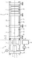
- In der nachfolgenden Figur wird beispielhaft eine erfindungsgemäße Montagevorrichtung sowie deren Verwendung bei einem Elektrolyseur skizziert. Es zeigt dabei die
- FIG
- einen Längsschnitt durch einen Elektrolyseur mit mechanisch verbundener Montagevorrichtung.
- In der Figur ist ein Elektrolyseur 3 dargestellt, der sich entlang einer Längsachse X erstreckt und an dieser linear ausgerichtet ist. Der Elektrolyseur 3 weist einen Elektrolysestack 5 auf. Der Elektrolysestack 5 umfasst drei im wesentlichen baugleiche Unterbaugruppen, die Segmente 25, die entlang der Längsachse X aufeinander folgend angeordnet sind. Jedes der Segmente 25 weist hierbei eine Vielzahl von entlang der Längsachse X gestapelten Elektrolysezellen 7 auf. Ein Segment 25 ist jeweils von einer Endplatten 29 axial aufwärts sowie eine Endplatte 29 axial abwärts begrenzt. Die Endplatten 29 schließen die Elektrolysezellen 7 des jeweiligen Segments 25 ein und begrenzen diese Unterbaugruppe.
- Auf diese Weise sind bei dem Elektrolyseur 3 beispielsweise fünfzig Elektrolysezellen axial zu einem Segment 25 gestapelt und wiederum beispielsweise fünf Segmente zu einem Elektrolsestack 5 in axialer Richtung gestapelt, so dass ein solcher Elektrolysestack 5 mithin beispielsweise 250 Zellen in einem axialen Gesamtverbund umfasst. Die Zahlen sind nur exemplarisch und können je nach Auslegung und Konstruktion des Elektrolyseurs 5 auch anders gewählt werden. In der Figur sind daher aus Übersichtlichkeitsgründen drei Segmente 25 gezeigt. Diese Auslegung ist aber im konkreten Anwendungsfall skalierbar und anpassbar an die jeweiligen Anforderungen.
- Bei dem Elektrolysestack 5 ist die Vielzahl der Elektrolysezellen 5 entlang der axialen Richtung mittels eines Zentriergestänges 21 dicht gestapelt, so dass zusammen mit den Endplatten 29 ein Zellverbund als Teil des Elektrolysestacks 5 gebildet ist. Im Ausführungsbeispiel weist das Zentriergestänge 21 vier achsparallele Stangen 23 auf, die an der Peripherie des Elektrolysestacks 5 angeordnet sind. Dieser Zellverbund im Elektrolysestack 5 ist für den Betrieb des Elektrolyseurs 3 druckdicht für das Arbeitsmittel und die Elektrolyseprodukte, etwa Wasser für die Wasserelektrolyse mit den Produktgasen Wasserstoff und Sauerstoff, auszuführen. Des Weiteren ist für den Betrieb eine sehr gute und vor allem gleichmäßige elektrische Kontaktierung zwischen den benachbarten Elektrolysezellen 7 für eine verlustarme elektrische Reihenschaltung auszuführen.
- Der gesamte Elektrolyseur 3 ist über massive metallische Endplatten 29 des Elektrolysestack 5 auf einem Auflager 31, einem so genannten Loslager, gelagert, und entsprechend beweglich bzw. verschiebbar entlang der Längsachse. Das Auflager 31 lässt hierbei axiale Verschiebungen des gesamten Elektrolysestacks 5 zu, wie sie etwa betriebsbedingt im Elektrolyseur 3 durch temperaturbedingte Längenausdehnungen, oder, wie für die vorliegende Erfindung bedeutsam, unter Anwendung einer externen mechanischen Pressung des Elektrolysestacks 5 durch Beaufschlagung mit einer extern aufgebrachten Axialkraft F für die Erstmontage oder den Servicefall, je nach Bedarf.
- Um die erforderliche mechanische Pressung bedarfsweise und flexibel zu ermöglichen und für den Betrieb des Elektrolysestacks 5 einzustellen, ist die Montagevorrichtung 1 entsprechend vorteilhaft konfektioniert. Die Montagevorrichtung umfasst eine Hydraulikbaugruppe 9 mit einer Druckplatte 11, mit einem Aktor 13 und mit einer Aufnahme 15 zur lösbaren Verbindung mit dem Elektrolysestack 5. Bei Aktivierung der Hydraulikbaugruppe durch die Axialkraft F ist die mechanische Pressung des Elektrolysestacks 5 bewirkbar. Dabei ist die Druckplatte 11 derart ausgeführt, dass diese ein Festlager 33 bildet, so dass bei Aktivierung der Hydraulikbaugruppe 9 sich die Hydraulikbaugruppe 9 gegen das Festlager 33 abstützt. Die Aufnahme 15 ist als lösbare Schraubverbindung in Form einer Überwurfhülse ausgeführt, die in ein entsprechendes Gewinde 35 des Elektrolysestacks 5 im montierten Zustand eingreift und dieses umschließt. Vorliegend ist die Aufnahme 15 eine Überwurfhülse mit entsprechendem Innengewinde ausgestaltet. Zur Drucküberwachung und Einstellung der gewünschten Axialkraft F über den hydraulischen Druck ist ein Druckmessgerät 17 vorgesehen. Eine Hydraulikpumpe 19 sorgt für das gewünschte Druckniveau zur Aktivierung des Pressvorgangs und fördert unter Druck P das Betriebsmittel B, etwa ein Hydrauliköl, zum hydraulischen Vortrieb des Aktors 13. Auf diese Weise ist eine vorbestimmbare Axialverschiebung Δ1 des Aktors 13 bewirkbar, die proportional zur Axialkraft F bzw. dem Druck P ist, so dass bei Aktivierung der Hydraulikbaugruppe 19 durch die Axialkraft F eine vorbestimmte mechanische Pressung des Elektrolysestacks 5 bewirkt ist. Ist der gewünschte Verspannungszustand des Elektrolysestacks 5 erreicht, so wird dieser Verspannungszustand am Elektrolysestack 5 fixiert und gehalten. Typischerweise können Flächenpressungen im Bereich von etwa 10 -100 N / cm2 eingestellt werden, vorzugsweise etwa 40 - 60 N / cm2. Es können bedarfsweise auch größere Flächenpressungen angewendet werden.
- Mit der Erfindung wird der Gesamtverbund aus der Vielzahl von Elektrolysezellen 7 Zellen in dem Elektrolysestack 5 für den Betrieb unter einem gewünschten Betriebsdruck des Elektrolyseurs 3 funktionsfähig und betriebsbereit mittels der Montagevorrichtung 1 eingestellt. Dieser Verspannungszustand des Elektrolysestacks 5 wird dabei mittels geeigneter Verschraubung oder Fixierelementen beim Elektrolysestack 5 fixiert und die Aufnahme 15 der Montagevorrichtung 1 anschließend wieder gelöst, um die Montagevorrichtung 1 von dem Elektrolysestack 5 zu entfernen. Die Montagevorrichtung 1 selbst muss hier im Weiteren nicht dauerhaft dafür sorgen, die Flächenpressung des Elektrolysestacks 5 zu erhalten bzw. diese zu fixieren Die Montagevorrichtung verbleibt nicht am Elektrolysestack 5, was sehr vorteilhaft ist. Sie wird anderen Verwendungen dieser Art zugeführt, d.h. die Montagevorrichtung 1 kann flexibel für Einstellarbeiten bei der Erstmontage und Inbetriebnahme von weiteren Elektrolyseuren, insbesondere aber auch für Service, Diagnostik des Verspannungszustands und Wartung an bereits im Betrieb befindlichen Elektrolyseuren 5 eingesetzt werden.
Claims (12)
- Montagevorrichtung (1) zur Verwendung in einem Elektrolyseur (3) zur mechanischen Pressung einer Vielzahl von in axialer Richtung zueinander zentriert zu einem Elektrolysestack (5) angeordneter Elektrolysezellen (7) durch Aufbringen einer Axialkraft (F), umfassend eine Hydraulikbaugruppe (9) mit einer Druckplatte (11), mit einem Aktor (13) und mit einer Aufnahme (15) zur lösbaren Verbindung mit dem Elektrolysestack (5) derart, dass bei Aktivierung der Hydraulikbaugruppe durch die Axialkraft (F) die mechanische Pressung bewirkbar ist.
- Montagevorrichtung (1) nach Anspruch 1, wobei die Druckplatte (11) derart ausgeführt ist, dass diese bei Aktivierung der Hydraulikbaugruppe (9) das Festlager bildet, gegen die sich die Hydraulikbaugruppe (9) abstützt.
- Montagevorrichtung (1) nach Anspruch 1 oder 2, wobei die Aufnahme (15) eine lösbare Schraubverbindung aufweist, die insbesondere als Überwurfhülse mit Innengewinde ausgestaltet ist.
- Montagevorrichtung (1) nach einem der vorhergehenden Ansprüche, wobei ein Druckmessgerät (17) zur Einstellung der Axialkraft (F) über den hydraulischen Druck vorgesehen ist.
- Montagevorrichtung (1) nach einem der vorhergehenden Ansprüche, wobei eine Hydraulikpumpe (19) zur Aktivierung vorgesehen ist, mittels derer Betriebsmittel (B) förderbar ist.
- Verwendung einer Montagevorrichtung (1) nach einem der vorhergehenden Ansprüche bei der Montage von Elektrolysezellen (7) eines Elektrolyseurs (3).
- Verwendung nach Anspruch 6, der eine Vielzahl von Elektrolysezellen (7) in axialer Richtung zueinander zentriert zu einem Elektrolysestack (5) angeordnet werden, wobei die Hydraulikbaugruppe (9) mit dem Elektrolysestack (5) mechanisch derart verbunden wird, dass bei Aktivierung der Hydraulikbaugruppe (9) eine mechanische Pressung des Elektrolysestack (5) durch eine Axialkraft (F) bewirkt ist.
- Verwendung nach Anspruch 6 oder 7, bei der die Axialkraft (F) derart eingestellt wird, bis ein vorbestimmter Verspannungszustand durch die Flächenpressung der Elektrolysezellen (7) in dem Elektrolysestack (5) erzielt ist.
- Verwendung nach Anspruche 8, bei der der Verspannungszustand des Elektrolysestacks (5) fixiert wird.
- Verwendung nach Anspruch 6 oder 7, bei der nach Fixierung des Verspannungszustand die mechanische Verbindung der Hydraulikbaugruppe (1) von dem Elektrolysestack (5) gelöst wird.
- Verwendung nach einem der Ansprüche 6 bis 10, angewendet bei einem Elektrolysestack (5) umfassend eine Vielzahl von Elektrolysezellen (7), die entlang der axialen Richtung mittels eines Zentriergestänges (21) dicht gestapelt sind.
- Verwendung nach Anspruch 11, bei der das Zentriergestänge (21) eine Anzahl von achsparallelen Stangen (23) aufweist, die an der Peripherie des Elektrolysestacks (5) angeordnet sind.
Priority Applications (6)
| Application Number | Priority Date | Filing Date | Title |
|---|---|---|---|
| EP21182760.5A EP4112782A1 (de) | 2021-06-30 | 2021-06-30 | Montagevorrichtung sowie verwendung der montagevorrichtung zur montage von elektrolysezellen eines elektrolyseurs |
| US18/572,880 US20240343010A1 (en) | 2021-06-30 | 2022-06-15 | Mounting device and use of the mounting device for mounting electrolysis cells of an electrolyser |
| CN202280045880.7A CN117597473A (zh) | 2021-06-30 | 2022-06-15 | 装配装置以及该装配装置用于装配电解器的电解单池的应用 |
| EP22734915.6A EP4334505A1 (de) | 2021-06-30 | 2022-06-15 | Montagevorrichtung sowie verwendung der montagevorrichtung zur montage von elektrolysezellen eines elektrolyseurs |
| CA3225635A CA3225635A1 (en) | 2021-06-30 | 2022-06-15 | Mounting device and use of the mounting device for mounting electrolysis cells of an electrolyser |
| PCT/EP2022/066374 WO2023274731A1 (de) | 2021-06-30 | 2022-06-15 | Montagevorrichtung sowie verwendung der montagevorrichtung zur montage von elektrolysezellen eines elektrolyseurs |
Applications Claiming Priority (1)
| Application Number | Priority Date | Filing Date | Title |
|---|---|---|---|
| EP21182760.5A EP4112782A1 (de) | 2021-06-30 | 2021-06-30 | Montagevorrichtung sowie verwendung der montagevorrichtung zur montage von elektrolysezellen eines elektrolyseurs |
Publications (1)
| Publication Number | Publication Date |
|---|---|
| EP4112782A1 true EP4112782A1 (de) | 2023-01-04 |
Family
ID=76730353
Family Applications (2)
| Application Number | Title | Priority Date | Filing Date |
|---|---|---|---|
| EP21182760.5A Withdrawn EP4112782A1 (de) | 2021-06-30 | 2021-06-30 | Montagevorrichtung sowie verwendung der montagevorrichtung zur montage von elektrolysezellen eines elektrolyseurs |
| EP22734915.6A Pending EP4334505A1 (de) | 2021-06-30 | 2022-06-15 | Montagevorrichtung sowie verwendung der montagevorrichtung zur montage von elektrolysezellen eines elektrolyseurs |
Family Applications After (1)
| Application Number | Title | Priority Date | Filing Date |
|---|---|---|---|
| EP22734915.6A Pending EP4334505A1 (de) | 2021-06-30 | 2022-06-15 | Montagevorrichtung sowie verwendung der montagevorrichtung zur montage von elektrolysezellen eines elektrolyseurs |
Country Status (5)
| Country | Link |
|---|---|
| US (1) | US20240343010A1 (de) |
| EP (2) | EP4112782A1 (de) |
| CN (1) | CN117597473A (de) |
| CA (1) | CA3225635A1 (de) |
| WO (1) | WO2023274731A1 (de) |
Cited By (3)
| Publication number | Priority date | Publication date | Assignee | Title |
|---|---|---|---|---|
| DE102023207495A1 (de) * | 2023-08-04 | 2025-02-06 | Robert Bosch Gesellschaft mit beschränkter Haftung | Verfahren zur Vorspannung und Herstellung einer elektrochemischen Zelleneinheit |
| EP4534727A1 (de) * | 2023-10-05 | 2025-04-09 | thyssenkrupp nucera AG & Co. KGaA | Spannvorrichtung, elektrolyseur, verfahren zum schliessen/öffnen benachbarter elektrolysezellen, verfahren zum nachträglichen anbringen einer spannvorrichtung |
| EP4534726A1 (de) * | 2023-10-05 | 2025-04-09 | thyssenkrupp nucera AG & Co. KGaA | Spannvorrichtung, elektrolyseur, verfahren zum verschliessen/bestücken benachbarter elektrolysezellen, verfahren zum nachträglichen anbringen einer spannvorrichtung |
Families Citing this family (1)
| Publication number | Priority date | Publication date | Assignee | Title |
|---|---|---|---|---|
| DE102023124962B4 (de) | 2023-09-15 | 2025-05-15 | Schaeffler Technologies AG & Co. KG | Vorrichtung und Verfahren zur Demontage eines Stapels elektrochemischer Zellen |
Citations (4)
| Publication number | Priority date | Publication date | Assignee | Title |
|---|---|---|---|---|
| US4430179A (en) * | 1981-08-03 | 1984-02-07 | Olin Corporation | Portable method for filter press cell assembly |
| US4846952A (en) * | 1988-07-15 | 1989-07-11 | The Dow Chemical Company | Flat plate electrolysis cell frame separator and method |
| EP2617874A1 (de) * | 2012-01-18 | 2013-07-24 | H-TEC Systems GmbH | Elektrolyseur |
| WO2020203319A1 (ja) * | 2019-04-01 | 2020-10-08 | 旭化成株式会社 | 電解槽及びその制御方法並びにプログラム |
-
2021
- 2021-06-30 EP EP21182760.5A patent/EP4112782A1/de not_active Withdrawn
-
2022
- 2022-06-15 CA CA3225635A patent/CA3225635A1/en active Pending
- 2022-06-15 EP EP22734915.6A patent/EP4334505A1/de active Pending
- 2022-06-15 CN CN202280045880.7A patent/CN117597473A/zh active Pending
- 2022-06-15 US US18/572,880 patent/US20240343010A1/en active Pending
- 2022-06-15 WO PCT/EP2022/066374 patent/WO2023274731A1/de not_active Ceased
Patent Citations (4)
| Publication number | Priority date | Publication date | Assignee | Title |
|---|---|---|---|---|
| US4430179A (en) * | 1981-08-03 | 1984-02-07 | Olin Corporation | Portable method for filter press cell assembly |
| US4846952A (en) * | 1988-07-15 | 1989-07-11 | The Dow Chemical Company | Flat plate electrolysis cell frame separator and method |
| EP2617874A1 (de) * | 2012-01-18 | 2013-07-24 | H-TEC Systems GmbH | Elektrolyseur |
| WO2020203319A1 (ja) * | 2019-04-01 | 2020-10-08 | 旭化成株式会社 | 電解槽及びその制御方法並びにプログラム |
Cited By (5)
| Publication number | Priority date | Publication date | Assignee | Title |
|---|---|---|---|---|
| DE102023207495A1 (de) * | 2023-08-04 | 2025-02-06 | Robert Bosch Gesellschaft mit beschränkter Haftung | Verfahren zur Vorspannung und Herstellung einer elektrochemischen Zelleneinheit |
| EP4534727A1 (de) * | 2023-10-05 | 2025-04-09 | thyssenkrupp nucera AG & Co. KGaA | Spannvorrichtung, elektrolyseur, verfahren zum schliessen/öffnen benachbarter elektrolysezellen, verfahren zum nachträglichen anbringen einer spannvorrichtung |
| EP4534726A1 (de) * | 2023-10-05 | 2025-04-09 | thyssenkrupp nucera AG & Co. KGaA | Spannvorrichtung, elektrolyseur, verfahren zum verschliessen/bestücken benachbarter elektrolysezellen, verfahren zum nachträglichen anbringen einer spannvorrichtung |
| WO2025073681A1 (en) * | 2023-10-05 | 2025-04-10 | thyssenkrupp nucera AG & Co. KGaA | Tightening apparatus, electrolyser, method of closing/opening adjacent electrolysis cells, method of retroactively applying tightening apparatus |
| WO2025073679A1 (en) * | 2023-10-05 | 2025-04-10 | thyssenkrupp nucera AG & Co. KGaA | Tightening apparatus, electrolyser, method of closing/opening adjacent electrolysis cells, method of retroactively applying tightening apparatus |
Also Published As
| Publication number | Publication date |
|---|---|
| CN117597473A (zh) | 2024-02-23 |
| CA3225635A1 (en) | 2023-01-05 |
| US20240343010A1 (en) | 2024-10-17 |
| EP4334505A1 (de) | 2024-03-13 |
| WO2023274731A1 (de) | 2023-01-05 |
Similar Documents
| Publication | Publication Date | Title |
|---|---|---|
| EP4112782A1 (de) | Montagevorrichtung sowie verwendung der montagevorrichtung zur montage von elektrolysezellen eines elektrolyseurs | |
| EP2617874B1 (de) | Elektrolyseur | |
| DE102016205282B3 (de) | Brennstoffzellenstapel mit Spannvorrichtung sowie Verfahren zum Betreiben eines Brennstoffzellenstapels | |
| WO2021155919A1 (de) | Verfahren zum betreiben einer elektrochemischen zellstapelanordnung | |
| DE102017215748B4 (de) | Kompressionsvorrichtung für einen Brennstoffzellenstapel | |
| DE102021004963A1 (de) | Vorrichtung zur Verspannung eines Brennstoffzellenstapels oder Elektrolysezellenstapels | |
| WO2011026544A1 (de) | Brennstoffzellenstapelabschnitt sowie verfahren zur montage des brennstoffzellenabschnitts | |
| DE102016205284A1 (de) | Brennstoffzellenstapel mit Spannvorrichtung | |
| DE102008052945A1 (de) | Brennstoffzellenstapel | |
| DE202016101811U1 (de) | Brennstoffzellenstapel mit Spannvorrichtung | |
| AT527258B1 (de) | Elektrolysezelle und Elektrolysevorrichtung mit einer Elektrolysezelle | |
| DE102024208119A1 (de) | Elektrolyseur | |
| DE102019219791A1 (de) | Brennstoffzelle mit einer Nachstellvorrichtung zum Ausgleich des Setzverhaltens innerhalb eines Stapelaufbaus | |
| DE102022109188B3 (de) | Brennstoffzellenstapel und Verfahren zur Montage eines Brennstoffzellenstapels | |
| DE102019218870A1 (de) | Brennstoffzelle, Brennstoffzellenstapel sowie Verfahren zum Betreiben eines Brennstoffzellenstapels | |
| EP2292343A1 (de) | Vorrichtung zur elektrohydraulischen Blechumformung | |
| DE10235859B4 (de) | Korrosionsstabiler, gasdichter Medienanschluss für Niedertemperatur-Brennstoffzellen | |
| DE10151452A1 (de) | Brennstoffzellenstapel | |
| EP3621139A1 (de) | Elektrochemische energieumwandlungsvorrichtung | |
| EP1605538B1 (de) | Verspannung einer Niedertemperatur-Brennstoffzelle | |
| DE102022113312A1 (de) | Zellstapelpaket | |
| EP4596754A1 (de) | Einstellung des anpressdrucks in einem elektrolysestack | |
| WO2023186988A1 (de) | Spannsystem, brennstoffzellenanordnung, fahrzeug und herstellverfahren für eine brennstoffzellenanordnung | |
| EP4713504A1 (de) | Elektrolysezelle, elektrolyseblock mit mehreren entsprechenden elektrolysezellen, und elektrolysevorrichtung mit mehreren entsprechenden elektrolysezellen | |
| WO2025233183A1 (de) | Elektrochemische vorrichtung |
Legal Events
| Date | Code | Title | Description |
|---|---|---|---|
| PUAI | Public reference made under article 153(3) epc to a published international application that has entered the european phase |
Free format text: ORIGINAL CODE: 0009012 |
|
| STAA | Information on the status of an ep patent application or granted ep patent |
Free format text: STATUS: THE APPLICATION HAS BEEN PUBLISHED |
|
| AK | Designated contracting states |
Kind code of ref document: A1 Designated state(s): AL AT BE BG CH CY CZ DE DK EE ES FI FR GB GR HR HU IE IS IT LI LT LU LV MC MK MT NL NO PL PT RO RS SE SI SK SM TR |
|
| STAA | Information on the status of an ep patent application or granted ep patent |
Free format text: STATUS: THE APPLICATION IS DEEMED TO BE WITHDRAWN |
|
| 18D | Application deemed to be withdrawn |
Effective date: 20230705 |