EP4112466A1 - Automated cart systems and methods for an internal cabin of a vehicle - Google Patents
Automated cart systems and methods for an internal cabin of a vehicle Download PDFInfo
- Publication number
- EP4112466A1 EP4112466A1 EP22181143.3A EP22181143A EP4112466A1 EP 4112466 A1 EP4112466 A1 EP 4112466A1 EP 22181143 A EP22181143 A EP 22181143A EP 4112466 A1 EP4112466 A1 EP 4112466A1
- Authority
- EP
- European Patent Office
- Prior art keywords
- inventory
- waste
- cart system
- housing
- user interface
- Prior art date
- Legal status (The legal status is an assumption and is not a legal conclusion. Google has not performed a legal analysis and makes no representation as to the accuracy of the status listed.)
- Pending
Links
- 238000000034 method Methods 0.000 title abstract description 30
- 239000002699 waste material Substances 0.000 claims description 77
- 238000004891 communication Methods 0.000 description 23
- 230000015654 memory Effects 0.000 description 13
- 230000000712 assembly Effects 0.000 description 7
- 238000000429 assembly Methods 0.000 description 7
- 229920002492 poly(sulfone) Polymers 0.000 description 7
- 235000013361 beverage Nutrition 0.000 description 6
- 238000013500 data storage Methods 0.000 description 5
- 238000010586 diagram Methods 0.000 description 5
- 235000013305 food Nutrition 0.000 description 4
- 230000004044 response Effects 0.000 description 4
- XAGFODPZIPBFFR-UHFFFAOYSA-N aluminium Chemical compound [Al] XAGFODPZIPBFFR-UHFFFAOYSA-N 0.000 description 3
- 229910052782 aluminium Inorganic materials 0.000 description 3
- 238000013473 artificial intelligence Methods 0.000 description 3
- 230000006870 function Effects 0.000 description 3
- 238000004064 recycling Methods 0.000 description 3
- QVGXLLKOCUKJST-UHFFFAOYSA-N atomic oxygen Chemical compound [O] QVGXLLKOCUKJST-UHFFFAOYSA-N 0.000 description 2
- 238000004590 computer program Methods 0.000 description 2
- 230000008878 coupling Effects 0.000 description 2
- 238000010168 coupling process Methods 0.000 description 2
- 238000005859 coupling reaction Methods 0.000 description 2
- 238000007726 management method Methods 0.000 description 2
- 239000000463 material Substances 0.000 description 2
- 239000010847 non-recyclable waste Substances 0.000 description 2
- 230000003287 optical effect Effects 0.000 description 2
- 229910052760 oxygen Inorganic materials 0.000 description 2
- 239000001301 oxygen Substances 0.000 description 2
- 235000011888 snacks Nutrition 0.000 description 2
- 239000003381 stabilizer Substances 0.000 description 2
- 230000007704 transition Effects 0.000 description 2
- 230000006399 behavior Effects 0.000 description 1
- 235000020803 food preference Nutrition 0.000 description 1
- 235000019138 food restriction Nutrition 0.000 description 1
- 238000003331 infrared imaging Methods 0.000 description 1
- 230000003137 locomotive effect Effects 0.000 description 1
- 235000012054 meals Nutrition 0.000 description 1
- 238000012986 modification Methods 0.000 description 1
- 230000004048 modification Effects 0.000 description 1
- 239000010813 municipal solid waste Substances 0.000 description 1
- 230000008569 process Effects 0.000 description 1
- 238000005096 rolling process Methods 0.000 description 1
Images


Classifications
-
- B—PERFORMING OPERATIONS; TRANSPORTING
- B64—AIRCRAFT; AVIATION; COSMONAUTICS
- B64D—EQUIPMENT FOR FITTING IN OR TO AIRCRAFT; FLIGHT SUITS; PARACHUTES; ARRANGEMENTS OR MOUNTING OF POWER PLANTS OR PROPULSION TRANSMISSIONS IN AIRCRAFT
- B64D11/00—Passenger or crew accommodation; Flight-deck installations not otherwise provided for
- B64D11/0007—Devices specially adapted for food or beverage distribution services
Definitions
- Vehicles such as commercial aircraft are used to transport passengers between various locations.
- an attendant may periodically pass through an internal cabin to distribute refreshments.
- an attendant may push a galley cart through an aisle of an internal cabin.
- the galley cart retains beverages and snacks, for example. Passengers may select certain beverages and snacks from the attendant.
- known carts provide little to no opportunity for passengers to be able to customize orders. Additionally, access to items such as food and beverages may be limited to specific times during a flight, and service can be slow and limited with no options available for specific food restrictions and preferences.
- the cart system for an internal cabin of a vehicle.
- the cart system includes a housing, one or more wheels coupled to the housing, and a user interface disposed on a portion of the housing.
- the user interface is configured to allow an individual to view inventory and select one or more items of the inventory.
- the cart system also includes one or more inventory compartments configured to store the inventory, and one or more inventory sensors configured to detect the one or more items of the inventory.
- the cart system also includes an item dispensing sub-system configured to deliver the one or more items of the inventory for presentation to the individual.
- the item dispensing sub-system includes one or more actuators operatively coupled to one or more delivery members.
- the cart system also includes one or more waste compartments, and one or more waste sensors configured to detect a type of waste deposited into the one or more waste compartments.
- a sorter is configured to automatically sort waste into the one or more waster compartments.
- the cart system also includes one or more actuators operatively coupled to the one or more wheels.
- the one or more actuators are configured to automatically move the cart system within the internal cabin.
- the user interface is removably coupled to the housing.
- the user interface includes a display screen showing a passenger information selection area and an inventory selection area.
- Certain examples of the present disclosure provide a method for an internal cabin of a vehicle.
- the method includes showing, via a user interface disposed on a portion of a housing having one or more wheels coupled thereto, inventory of items; and allowing selection, via the user interface, of one or more of the items of the inventory.
- Certain examples of the present disclosure provide a vehicle including an internal cabin, and a cart system configured to move within the internal cabin, as described herein.
- the disclosure also relates to a cart system for an internal cabin of a vehicle, comprising a housing, one or more wheels coupled to the housing and a user interface disposed on a portion of the housing, wherein the user interface is configured to allow an individual to view inventory and select one or more items of the inventory.
- the cart system can further comprise one or more inventory compartments configured to store the inventory and one or more inventory sensors configured to detect the one or more items of the inventory.
- the cart system can further compris ean item dispensing sub-system configured to deliver the one or more items of the inventory for presentation to the individual.
- the item dispensing sub-system comprises one or more actuators operatively may be coupled to one or more delivery members.
- the cart system can further comprise one or more waste compartments; and one or more waste sensors configured to detect a type of waste deposited into the one or more waste compartments.
- the cart system may further comprise a sorter configured to automatically sort waste into the one or more waster compartments.
- the cart system can further comprise one or more actuators operatively coupled to the one or more wheels.
- the one or more actuators may be configured to automatically move the cart system within the internal cabin.
- the user interface can be removably coupled to the housing.
- the user interface may comprise a display screen showing a passenger information selection area and an inventory selection area.
- the disclosure also relates to a method for an internal cabin of a vehicle, comprising showing, via a user interface disposed on a portion of a housing having one or more wheels coupled thereto, inventory of items; and allowing selection, via the user interface, of one or more of the items of the inventory.
- the method may further comprise storing, within one or more inventory compartments of the housing, the inventory; and detecting, by one or more inventory sensors, the one or more items of the inventory.
- the method can further comprise delivering, by an item dispensing sub-system, the one or more items of the inventory for presentation.
- the method can further comprise sensing, by one or more waste sensors, a type of waste deposited into one or more waste compartments of the housing.
- the method can further comprise automatically sorting waste into the one or more waster compartments.
- the method can further comprise operatively coupling one or more actuators to the one or more wheels.
- the method can further comprise automatically moving, by the one or more actuators, a cart system within an internal cabin of a vehicle.
- the method can further comprise removing the user interface from the housing.
- the showing can comprise showing, on a display screen of the user interface, a passenger information selection area and an inventory selection area.
- the disclosure also relates to a vehicle comprising an internal cabin; and a cart system configured to move within the internal cabin, wherein the cart system comprises: a housing; one or more wheels coupled to the housing; one or more actuators operatively coupled to the one or more wheels, a user interface disposed on a portion of the housing, wherein the user interface is configured to allow an individual to view inventory and select one or more items of the inventory; one or more inventory compartments configured to store the inventory; one or more inventory sensors configured to detect the one or more items of the inventory; an item dispensing sub-system configured to deliver the one or more items of the inventory for presentation to the individual; one or more waste compartments; one or more waste sensors configured to detect a type of waste deposited into the one or more waste compartments; and a sorter configured to automatically sort waste into the one or more waster compartments.
- cart systems used to store passenger meals and other in-flight items can include temperature controlled chambers used to warm or cool the items, as desired, before boarding.
- the cart systems include a user interface having a screen that provides individuals with inventory data allowing them to correctly select pre-ordered items. Inventory can then be instantly updated creating more efficient service.
- the cart system is configured to automatically dispense and present selected items, automatically assist users, and reduce push/pull effort of heavy carts.
- the cart systems are adaptable to other uses including waste carts with all-in-one self-sorting or branded partnerships, promotion of new products on screen showing inventory in each cart and galley compartment (mobile panels, flight attendant panels, detached display that can connect to cart).
- the cart systems include automated item dispensing systems.
- the cart systems can include a full handle that helps flight attendants maneuver the cart systems better and wheels that have sensors for altitude and attitude for better breaking and maneuvering.
- the cart systems can be connected to network systems that provide attendants important information about the passengers and their orders.
- the cart systems can also include recycling compartment(s) for waste (for example, two or more internal compartments configured to sorting and storing waste for recycling).
- Waste sorting sensors can automatically sort paper, aluminum, and plastic into separate compartments.
- the cart systems can also be equipped with a wheel assist to reduce the physical exertion needed to push the carts up and down aisles.
- the cart systems can be sized and shaped according to the existing standard trolley dimensions so they can be fit into existing compartments within galleys.
- the wheels can be motorized. In this manner, the cart systems can be self-propelled, thereby helping attendants maneuver the cart systems.
- the cart system includes a housing, user interface having a screen supported by the housing for displaying inventory of items stored in the housing and/or a galley of a vehicle, an automated food and beverage dispensing sub-system, powered wheels controlled based on sensed data of altitude and attitude, a communication device for wireless communication to other systems in the cabin (for example, for data related to passengers, preferences, orders, etc.), and a control unit operatively coupled to various components, and configured to control operation of the cart system.
- the user interface can be removable.
- a crew member can attach to the cart system an existing smart mobile device such as a company phone or tablet.
- a recycling compartment(s) is supported in the housing for collecting/separating waste onboard, and includes waste sorting sensors for automatically sorting recyclables and waste in separate compartments.
- the control unit can control the powered wheels based on usage requirements to reduce the physical exertion needed to push the cart.
- the cart system can include proximity sensors (or other location sensing system) for purposes of fully or partially autonomous ground movement of the cart without the assistance from a person (or some assistance/oversight from a person). This can potentially replace the need for one or more crew members to serve passengers and/or collect waste.
- the cart system can include artificial intelligence features (such as via the control unit) to predict inventory, power usage, expected waste, and flight related aspects such as turbulence, altitude, attitude, flight time, etc. for purposes of controlling the powered wheels, inventory management, passenger preferences, etc.
- artificial intelligence features such as via the control unit
- flight related aspects such as turbulence, altitude, attitude, flight time, etc. for purposes of controlling the powered wheels, inventory management, passenger preferences, etc.
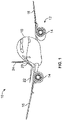
- Figure 1 illustrates a front perspective view of a vehicle, such as an aircraft 10, according to an example of the present disclosure.
- the aircraft 10 includes a propulsion system 12 that includes two engines 14, for example.
- the propulsion system 12 may include more engines 14 than shown.
- the engines 14 are carried by wings 16 of the aircraft 10.
- the engines 14 may be carried by a fuselage 18 and/or an empennage 20.
- the empennage 20 may also support horizontal stabilizers 22 and a vertical stabilizer 24.
- the fuselage 18 of the aircraft 10 defines an internal cabin, which may include a cockpit, one or more work sections (for example, galleys, personnel carry-on baggage areas, and the like), one or more passenger sections (for example, first class, business class, and coach sections), and an aft section. Each of the sections may be separated by a cabin transition area. Overhead stowage bin assemblies are positioned throughout the internal cabin.
- examples of the present disclosure may be used with various other vehicles, such as automobiles, buses, locomotives and train cars, seacraft, spacecraft, and the like.
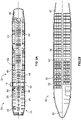
- FIG. 2A illustrates a top plan view of an internal cabin 30 of an aircraft, according to an example of the present disclosure.
- the internal cabin 30 may be within a fuselage 32 of the aircraft.
- one or more fuselage wall members may define the internal cabin 30.
- the internal cabin 30 includes multiple sections, including a front section 33, a first class section 34, a business class section 36, a front galley station 38, an expanded economy or coach section 40, a standard economy or coach section 42, and an aft section 44, which may include multiple lavatories and galley stations.
- the internal cabin 30 may include more or less sections than shown.
- the internal cabin 30 may not include a first class section, and may include more or less galley stations than shown.
- Each of the sections may be separated by a cabin transition area 46, which may include class divider assemblies between aisles 48.
- the internal cabin 30 includes two aisles 50 and 52 that lead to the aft section 44.
- the internal cabin 30 may have less or more aisles than shown.
- the internal cabin 30 may include a single aisle that extends through the center of the internal cabin 30 that leads to the aft section 44.
- a cart system can be used within the internal cabin 30.
- the cart system can be configured to be stored within a compartment within a galley. Passengers can select items from the cart system, dispose waste into the cart system, and the like, as described herein.
- Figure 2B illustrates a top plan view of an internal cabin 80 of an aircraft, according to an example of the present disclosure.
- the internal cabin 80 may be within a fuselage 81 of the aircraft.
- one or more fuselage wall members may define the internal cabin 80.
- the internal cabin 80 includes multiple sections, including a main cabin 82 having passenger seats 83, and an aft section 85 behind the main cabin 82. It is to be understood that the internal cabin 80 may include more or less sections than shown.
- the internal cabin 80 may include a single aisle 84 that leads to the aft section 85.
- the single aisle 84 may extend through the center of the internal cabin 80 that leads to the aft section 85.
- the single aisle 84 may be coaxially aligned with a central longitudinal plane 86 of the internal cabin 80.
- a cart system can be used within the internal cabin 80.
- the cart system can be configured to be stored within a compartment within a galley. Passengers can select items from the cart system, dispose waste into the cart system, and the like, as described herein.
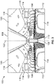
- FIG 3 illustrates an interior perspective view of an internal cabin 100 of an aircraft, according to an example of the present disclosure.
- the internal cabin 100 includes outboard wall members 102 and a ceiling 104, which may include a plurality of ceiling panels. Windows 106 may be formed within the outboard wall members 102.
- a floor member 108 supports rows of seats 110. As shown in Figure 3 , a row 112 may include two seats 110 on either side of an aisle 113. However, the row 112 may include more or less seats 110 than shown. Additionally, the internal cabin 100 may include more aisles than shown.
- Passenger service unit (PSUs) 114 are secured between an outboard wall member 102 and the ceiling 104 on either side of the aisle 113.
- the PSUs 114 extend between a front end and rear end of the internal cabin 100.
- a PSU 114 may be positioned over each seat 110 within a row 112.
- Each PSU 114 may include a housing 116 that generally contains passenger air outlets, reading lights, an oxygen supply system (such as an oxygen bag drop panel), an attendant call button, and other such controls over each seat 110 (or groups of seats) within a row 112.
- Overhead stowage bin assemblies 118 are secured to the structure proximate to the ceiling 104 and/or the outboard wall member 102 above and inboard from the PSU 114 on either side of the aisle 113.
- the overhead stowage bin assemblies 118 are secured over the seats 110.
- the overhead stowage bin assemblies 118 extend between the front and rear end of the internal cabin 100.
- Each stowage bin assembly 118 may include a pivot bin or bucket 120 pivotally secured to a strongback (hidden from view in Figure 3 ).
- the overhead stowage bin assemblies 118 may be positioned above and inboard from lower surfaces of the PSUs 114.
- the overhead stowage bin assemblies 118 are configured to be pivoted open in order to receive passenger carry-on baggage and personal items, for example.
- outboard means a position that is further away from a central longitudinal plane 122 of the internal cabin 100 as compared to another component.
- inboard means a position that is closer to the central longitudinal plane 122 of the internal cabin 100 as compared to another component.
- a lower surface of a PSU 114 may be outboard in relation to a stowage bin assembly 118.
- a cart system can be used within the internal cabin 100.
- the cart system can be configured to be stored within a compartment within a galley. Passengers can select items from the cart system, dispose waste into the cart system, and the like, as described herein.
- FIG. 4 illustrates a schematic block diagram of a cart system 200, according to an example of the present disclosure.
- the cart system 200 includes a housing 202, such as can be defined by a base, one or more outer walls, an upper panel, and/or the like.
- a user interface 204 is disposed on the housing 202, such as on a front and/or top panel.
- the user interface 204 includes a monitor or the like that allows information to be electronically displayed.
- the user interface 204 includes a display screen 206.
- the user interface 204, including the display screen 206 can be a touchscreen interface configured to electrically show information thereon, and allow for touchscreen selection.
- the user interface 204 is in communication with a control unit 208, such as through one or more wired or wireless connections.
- the control unit 208 is configured to control various aspects of the cart system 200, as described herein.
- the control unit 208 is also in communication with a communication device 210, such as through one or more wired or wireless connections.
- the communication device 210 can be on or more of an antenna, a transceiver, a transmitter, a receiver, and/or the like that allows the control unit 208 to wirelessly communicate with various remote systems, such as within a vehicle, outside of a vehicle, or the like.
- the cart system 200 does not include the communication device 210.
- the housing 202 also includes one or more inventory compartments 212 configured to store various items of inventory, such as food items, beverages, and/or the like.
- One or more sensors 214 are disposed within the one or more inventory compartments 212.
- the sensor(s) 214 can be optical devices, such as cameras, bar code readers, infrared imaging devices, ultrasonic sensors, and/or the like that are configured to detect the items of inventory within the inventory compartment(s) 212.
- the control unit 208 is in communication with the sensor 214, such as through one or more wired or wireless connections. As such, the control unit 208 is able to monitor and determine the items of inventory within the inventory compartment(s) 212 through communication with the sensors 214.
- the cart system 200 does not include the sensor 214.
- the housing 202 also includes an item dispensing sub-system 216, such as within at least a portion of the inventory compartment(s) 212.
- the item dispensing sub-system 216 is configured to deliver one or more selected items of the inventory for presentation to an individual who selected such item(s).
- the item dispensing sub-system 216 includes one or more actuators 218 (such as motors) operatively coupled to one or more delivery members 220 (such as one or more arms, conveyors, clasps, hooks, chutes, tubes, and/or the like).
- the actuators 218 and delivery members 220 are configured to engage one or more selected items of inventory for delivery outside of the housing.
- the item dispensing sub-system 216 is configured to pick up a selected item of inventory within the inventory compartment(s) 212, and move the selected item of inventory outside of the housing 202, such as onto an upper panel to be presented to an individual who selected the item.
- the control unit 208 is in communication with the item dispensing sub-system 216, such as through one or more wired or wireless connections, and is configured to control the item dispensing sub-system 216 based on a selection of item of inventory.
- the cart system 200 does not include the item dispensing sub-system 216.
- the housing 202 also includes one or more waste compartments 222.
- One or more sensors 224 can be disposed proximate (such as at) an inlet to the waste compartments 222.
- the sensor(s) 224 are configured to detect a type of waste deposited into the one or more waste compartments 222.
- the sensors 224 can be weight sensors, pressure sensors, optical sensors, and/or the like that are configured to detect and identify an item of waste that is deposited into the waste compartment(s) 222.
- the sensors 224 are in communication with the control unit 208, such as through one or more wire or wireless connections.
- the control unit 208 can also be in communication with a sorter 226 (such as a moveable shunt, arm, chute, and/or the like), such as through one or more wired or wireless connections.
- the sorter 226 is configured to automatically sort deposited waste into an appropriate waste compartment 222.
- the housing 202 includes three waste compartments, one for paper, one or aluminum, and one for non-recyclable waste.
- the control unit 208 determines the type of waste deposited into the waste compartments 222 through the sensor 224, and operates the sorter 226 to deposit the deposited waste into the appropriate waste compartment 222.
- the cart system 200 may not include the waste compartment(s) 222, the sensors 224, and/or the sorter 226.
- the cart system 200 also include one or more wheels 228, which are configured to provide rolling support on a surface, such as a floor of an internal cabin.
- One or more of the wheels 228 can be operatively coupled to one or more actuators 230 (such as motors) and/or brakes 232.
- the actuators 230 are configured to provide propulsion to the wheels 228, so that the cart system 200 can be automatically moved (or at least assist in manually moving) within an environment, such as an internal cabin of a vehicle.
- the control unit 208 can be in communication with the actuators 230 and/or the brakes 232, such as via one or more wired or wireless connections, to control operation thereof.
- the control unit 208 is not configured to control operation of the actuators 230 and/or the brakes 232.
- the wheels 228 are not operatively coupled to the actuators 230 and/or the brakes 232.
- control unit 208 is configured to automatically determine the items of inventory within the inventor compartment(s) 212 via the sensor(s) 214. Accordingly, the control unit 208 can then send one or more signals to the user interface 204 to display the available inventory on the display screen 206 to an individual.
- the control unit 208 can also be in communication with an inventory within a galley, such as via the communication device 210, and configured to display available items stored within the galley on the display screen 206.
- the individual is able to view the items of inventory via the user interface 204. Further, the individual is able to select one or more items of inventory through the user interface 204.
- the user interface 204 can be removable.
- an individual such as a passenger or crew member
- the handheld device can then provide the user interface 204.
- control unit 208 In response to an individual selecting an item of inventory within the inventory compartment(s) 212, the control unit 208 operates the item dispensing sub-system 216 to acquire the item, and move the item to a presentation area (such as on a top panel of the housing 202) for the individual. The control unit 208 can then update the inventory (based on the selected item(s)), thereby improving service efficiency.
- control unit 208 can control the actuators 230 and/or the brakes 232 operatively coupled to the wheels 228 to automatically move the cart system 200 within an internal cabin, and/or assist with movement thereof. That is, the control unit 208 can control the powered wheels based on usage requirements to reduce the physical exertion needed to push the cart.
- the control unit 208 is in communication with a navigation sub-system 234 (such as a local positioning system, a global positioning system, or the like) that is configured to determine the location of the cart system 200 within an environment, such as an internal cabin of a vehicle.
- the control unit 208 is configured to control operation of the actuators 230 and/or the brakes 232 to automatically move the cart system 200 within the environment based on the detected position of the cart system 200, as determined by the navigation sub-system 234.
- the cart system 200 may not include the navigation sub-system 234.
- the cart system can include proximity sensors (or other location sensing system) for purposes of fully or partially autonomous ground movement of the cart system 200 without the assistance from a person (or some assistance/oversight from a person).
- control unit 208 can control the wheels 228, via the actuator(s) 230 and/or the brake(s) 232, based on sensed data of altitude and attitude.
- control unit 208 can be in communication with a flight computer of an aircraft, such as through the communication device 210, and operate the actuators 230 and/or the brakes based on altitude and attitude as monitored by the flight computer.
- the cart system 200 can include a full handle that helps flight attendants maneuver the cart system 200 better and the wheels 228 can further include sensors for determining altitude and attitude (instead of the control unit 208 controlling through communication with a flight computer, for example) for better breaking and maneuvering.
- the waste compartment(s) 222 can be configured for collecting and separating waste.
- the control unit 208 is in communication with the sensors 224 and the sorter 226 to automatically sort waste, such as recyclables, into separate compartments.
- the cart system 200 can include artificial intelligence features (such as via the control unit 208) to predict inventory, power usage, expected waste, and flight related aspects such as turbulence, altitude, attitude, flight time, etc. for purposes of controlling the powered wheels, inventory management, passenger preferences, etc.
- the control unit 208 can be in communication with a database, memory, and/or the like that stores passenger information.
- the control unit 208 can predict inventory based on data from previous trips of passengers scheduled for a trip.
- the control unit 208 can determine inventory for a trip (such as a flight of an aircraft) based on previous orders of the passengers. Further, the control unit 208 can analyze passenger and crew behavior/movements to better configure inventory for future trips.
- the cart system may not include the artificial intelligence features.
- the cart system 200 can be connected to network systems, such as via the communication device 210, that provide individuals information about the passengers and their orders.
- Figure 5 illustrates a schematic block diagram of a control unit 300, according to an example of the subject disclosure.
- the control unit 208 (shown in Figure 4 ) is configured as shown in Figure 5 .
- the control unit 300 includes at least one processor 302 in communication with a memory 304.
- the memory 304 stores instructions 306, received data 308, and generated data 310.
- the control unit 300 shown in Figure 5 is merely exemplary, and non-limiting.
- control unit central processing unit
- CPU central processing unit
- computer computer
- RISC reduced instruction set computers
- ASICs application specific integrated circuits
- the control unit 208 may be or include one or more processors that are configured to control operation, as described herein.
- the control unit 208 is configured to execute a set of instructions that are stored in one or more data storage units or elements (such as one or more memories), in order to process data.
- the control unit 208 may include or be coupled to one or more memories.
- the data storage units may also store data or other information as desired or needed.
- the data storage units may be in the form of an information source or a physical memory element within a processing machine.
- the set of instructions may include various commands that instruct the control unit 208 as a processing machine to perform specific operations such as the methods and processes of the various examples of the subject matter described herein.
- the set of instructions may be in the form of a software program.
- the software may be in various forms such as system software or application software. Further, the software may be in the form of a collection of separate programs, a program subset within a larger program, or a portion of a program.
- the software may also include modular programming in the form of object-oriented programming.
- the processing of input data by the processing machine may be in response to user commands, or in response to results of previous processing, or in response to a request made by another processing machine.
- the diagrams of examples herein may illustrate one or more control or processing units, such as the control unit 208.
- the processing or control units may represent circuits, circuitry, or portions thereof that may be implemented as hardware with associated instructions (e.g., software stored on a tangible and non-transitory computer readable storage medium, such as a computer hard drive, ROM, RAM, or the like) that perform the operations described herein.
- the hardware may include state machine circuitry hardwired to perform the functions described herein.
- the hardware may include electronic circuits that include and/or are connected to one or more logic-based devices, such as microprocessors, processors, controllers, or the like.
- control unit 208 may represent processing circuitry such as one or more of a field programmable gate array (FPGA), application specific integrated circuit (ASIC), microprocessor(s), and/or the like.
- FPGA field programmable gate array
- ASIC application specific integrated circuit
- microprocessor(s) and/or the like.
- the circuits in various examples may be configured to execute one or more algorithms to perform functions described herein.
- the one or more algorithms may include aspects of examples disclosed herein, whether or not expressly identified in a flowchart or a method.
- the terms "software” and “firmware” are interchangeable, and include any computer program stored in a data storage unit (for example, one or more memories) for execution by a computer, including RAM memory, ROM memory, EPROM memory, EEPROM memory, and non-volatile RAM (NVRAM) memory.
- a data storage unit for example, one or more memories
- NVRAM non-volatile RAM
- the above data storage unit types are exemplary only, and are thus not limiting as to the types of memory usable for storage of a computer program.
- Figure 6 illustrates a first perspective side view of the cart system 200, according to an example of the present disclosure.
- Figure 7 illustrates a front view of the cart system 200 of Figure 6.
- Figure 8 illustrates a second perspective side view of the cart system 200 of Figure 6 .
- the housing 202 includes a base 250.
- the wheels 228 are moveably coupled to a lower portion of the base 250.
- Outer walls 252 upwardly extend from the base 250.
- a door 254 is moveably coupled to at least one of the outer walls 252, such as a front panel.
- the door 254 is moveable between open and closed positions. When the door 254 is in the open position, the inventory compartment(s) 212 and/or the waste compartment(s) 222 are accessible.
- the user interface 204 is disposed on an outer surface of the housing 202, such as on a top panel.
- Figure 9 illustrates a perspective top view of the cart system 200, according to an example of the present disclosure.
- Figure 10 illustrates a perspective top view of the cart system 200 having an item 270 of inventory presented by the item dispensing sub-system 216, according to an example of the present disclosure.
- the delivery member 220 (such as a moveable tray) provides the item 270 for presentation such as proximate to a top panel of the housing 202.
- Figure 11 illustrates a perspective top view of the user interface 204 on the housing 202 of the cart system 200, according to an example of the present disclosure.
- the user interface 204 can be on a front panel and/or top panel of the housing 202.
- the user interface 204 can be at other locations than shown.
- the control unit 208 electronically controls the user interface 204.
- the user interfac3 204 can be a touchscreen interface 204 having a passenger information selection area 280, an inventory selection area 282, a flight information selection area 284, and/or the like. An individual can make various selections through the user interface 204.
- Figure 12 illustrates an internal view of a portion of the cart system 200, according to an example of the present disclosure.
- the housing 202 may contain one or more waste compartments 222, such as a first waste compartment 222a, a second waste compartment 222b, and a third waste compartment 222c, each of which may be configured to contain a different type of waste (such as recyclable paper, recycle aluminum, and non-recyclable waste).
- the sensor(s) 222 are located at or within a waste inlet chute 290 that leads to each of the waste compartments 222a, 222b, and 222c.
- the sorter 226 is above the waste compartments 222a, 222b, and 222c.
- the sorter 226 can include a moveable door, arm, or the like that is configured to direct a waste item 292 into an appropriate waste compartment 222, such as via the control unit 208 (shown in Figure 4 ) operating the sorter 226 based on the type of waste item detected by the sensor(s) 224.
- Figure 13 illustrates a flow chart of a method for an internal cabin of a vehicle, according to an example of the present disclosure.
- the method includes showing at 400, via the user interface 204 disposed on a portion of the housing 202 having one or more wheels 228 coupled thereto, inventory of items; and allowing selection at 402, via the user interface 204, of one or more of the items of the inventory.
- the method also includes storing, within one or more inventory compartments 212 of the housing 202, the inventory; and detecting, by one or more inventory sensors 214, the one or more items of the inventory.
- the method also includes delivering, by the item dispensing sub-system 216, the one or more items of the inventory for presentation.
- the method also includes sensing, by one or more waste sensors 224, a type of waste deposited into one or more waste compartments 222 of the housing 202.
- the method can also include automatically sorting waste into the one or more waster compartments 222.
- the method also includes operatively coupling one or more actuators 230 to the one or more wheels 228. Further, the method can include automatically moving, by the one or more actuators 230, the cart system 200 within an internal cabin of a vehicle.
- the method can include removing the user interface 204 from the housing 202.
- the showing may include showing, on a display screen 206 of the user interface 204, a passenger information selection area and an inventory selection area.
- examples of the present disclosure provide systems and methods for efficiently and effectively providing items to passengers aboard a vehicle during a trip. Further, examples of the present disclosure improved cart systems and methods, such as can be used within an internal cabin of a vehicle.
- a structure, limitation, or element that is "configured to” perform a task or operation is particularly structurally formed, constructed, or adapted in a manner corresponding to the task or operation.
- an object that is merely capable of being modified to perform the task or operation is not “configured to” perform the task or operation as used herein.
Abstract
Description
- Vehicles such as commercial aircraft are used to transport passengers between various locations. During a flight, an attendant may periodically pass through an internal cabin to distribute refreshments. For example, an attendant may push a galley cart through an aisle of an internal cabin. The galley cart retains beverages and snacks, for example. Passengers may select certain beverages and snacks from the attendant.
- However, manually maneuvering carts and delivering items therefrom poses certain drawbacks. For example, attendants and passengers may not be aware of the current inventory of various items during a flight, nor if there will be suitable inventory for a future flight. Additionally, manually inspecting a cart for desired items requested by passengers can be inefficient. For example, a passenger may request an item only to find out that the item is no longer available after the attendant searches the cart. Additionally, there can be ergonomic issues with heavy carts and safety issues with runaway carts that are improperly stowed. Further, sorting trash and waste stored within a cart can be a time consuming task that is susceptible to human error.
- Also, known carts provide little to no opportunity for passengers to be able to customize orders. Additionally, access to items such as food and beverages may be limited to specific times during a flight, and service can be slow and limited with no options available for specific food restrictions and preferences.
- A need exists for a system and a method for efficiently and effectively providing items to passengers aboard a vehicle during a trip. Further, a need exists for improved cart systems and methods, such as can be used within an internal cabin of a vehicle.
- With those needs in mind, certain examples of the present disclosure provide a cart system for an internal cabin of a vehicle. The cart system includes a housing, one or more wheels coupled to the housing, and a user interface disposed on a portion of the housing. The user interface is configured to allow an individual to view inventory and select one or more items of the inventory.
- In at least one example, the cart system also includes one or more inventory compartments configured to store the inventory, and one or more inventory sensors configured to detect the one or more items of the inventory.
- In at least one example, the cart system also includes an item dispensing sub-system configured to deliver the one or more items of the inventory for presentation to the individual. For example, the item dispensing sub-system includes one or more actuators operatively coupled to one or more delivery members.
- In at least one example, the cart system also includes one or more waste compartments, and one or more waste sensors configured to detect a type of waste deposited into the one or more waste compartments. As a further example, a sorter is configured to automatically sort waste into the one or more waster compartments.
- In at least one example, the cart system also includes one or more actuators operatively coupled to the one or more wheels. As an example, the one or more actuators are configured to automatically move the cart system within the internal cabin.
- In at least one example, the user interface is removably coupled to the housing.
- In at least one example, the user interface includes a display screen showing a passenger information selection area and an inventory selection area.
- Certain examples of the present disclosure provide a method for an internal cabin of a vehicle. The method includes showing, via a user interface disposed on a portion of a housing having one or more wheels coupled thereto, inventory of items; and allowing selection, via the user interface, of one or more of the items of the inventory.
- Certain examples of the present disclosure provide a vehicle including an internal cabin, and a cart system configured to move within the internal cabin, as described herein.
- Further, the disclosure also relates to a cart system for an internal cabin of a vehicle, comprising a housing, one or more wheels coupled to the housing and a user interface disposed on a portion of the housing, wherein the user interface is configured to allow an individual to view inventory and select one or more items of the inventory.
- The cart system can further comprise one or more inventory compartments configured to store the inventory and one or more inventory sensors configured to detect the one or more items of the inventory.
- The cart system can further compris ean item dispensing sub-system configured to deliver the one or more items of the inventory for presentation to the individual.
- The item dispensing sub-system comprises one or more actuators operatively may be coupled to one or more delivery members.
- The cart system can further comprise one or more waste compartments; and one or more waste sensors configured to detect a type of waste deposited into the one or more waste compartments.
- The cart system may further comprise a sorter configured to automatically sort waste into the one or more waster compartments.
- The cart system can further comprise one or more actuators operatively coupled to the one or more wheels.
- The one or more actuators may be configured to automatically move the cart system within the internal cabin.
- The user interface can be removably coupled to the housing.
- The user interface may comprise a display screen showing a passenger information selection area and an inventory selection area.
- The disclosure also relates to a method for an internal cabin of a vehicle, comprising showing, via a user interface disposed on a portion of a housing having one or more wheels coupled thereto, inventory of items; and allowing selection, via the user interface, of one or more of the items of the inventory.
- The method may further comprise storing, within one or more inventory compartments of the housing, the inventory; and detecting, by one or more inventory sensors, the one or more items of the inventory.
- The method can further comprise delivering, by an item dispensing sub-system, the one or more items of the inventory for presentation.
- The method can further comprise sensing, by one or more waste sensors, a type of waste deposited into one or more waste compartments of the housing.
- The method can further comprise automatically sorting waste into the one or more waster compartments.
- The method can further comprise operatively coupling one or more actuators to the one or more wheels.
- The method can further comprise automatically moving, by the one or more actuators, a cart system within an internal cabin of a vehicle.
- The method can further comprise removing the user interface from the housing.
- The showing can comprise showing, on a display screen of the user interface, a passenger information selection area and an inventory selection area.
- The disclosure also relates to a vehicle comprising an internal cabin; and a cart system configured to move within the internal cabin, wherein the cart system comprises: a housing; one or more wheels coupled to the housing; one or more actuators operatively coupled to the one or more wheels, a user interface disposed on a portion of the housing, wherein the user interface is configured to allow an individual to view inventory and select one or more items of the inventory; one or more inventory compartments configured to store the inventory; one or more inventory sensors configured to detect the one or more items of the inventory; an item dispensing sub-system configured to deliver the one or more items of the inventory for presentation to the individual; one or more waste compartments; one or more waste sensors configured to detect a type of waste deposited into the one or more waste compartments; and a sorter configured to automatically sort waste into the one or more waster compartments.
-
-
Figure 1 illustrates a front perspective view of an aircraft, according to an example of the present disclosure. -
Figure 2A illustrates a top plan view of an internal cabin of an aircraft, according to an example of the present disclosure. -
Figure 2B illustrates a top plan view of an internal cabin of an aircraft, according to an example of the present disclosure. -
Figure 3 illustrates an interior perspective view of an internal cabin of an aircraft, according to an example of the present disclosure. -
Figure 4 illustrates a schematic block diagram of a cart system, according to an example of the present disclosure. -
Figure 5 illustrates a schematic block diagram of a control unit, according to an example of the subject disclosure. -
Figure 6 illustrates a first perspective side view of a cart system, according to an example of the present disclosure. -
Figure 7 illustrates a front view of the cart system ofFigure 6 . -
Figure 8 illustrates a second perspective side view of the cart system ofFigure 6 . -
Figure 9 illustrates a perspective top view of the cart system, according to an example of the present disclosure. -
Figure 10 illustrates a perspective top view of the cart system having an item of inventory presented by an item dispensing sub-system, according to an example of the present disclosure. -
Figure 11 illustrates a perspective top view of a user interface on a housing of the cart system, according to an example of the present disclosure. -
Figure 12 illustrates an internal view of a portion of the cart system, according to an example of the present disclosure. -
Figure 13 illustrates a flow chart of a method for an internal cabin of a vehicle, according to an example of the present disclosure. - The foregoing summary, as well as the following detailed description of certain examples will be better understood when read in conjunction with the appended drawings. As used herein, an element or step recited in the singular and preceded by the word "a" or "an" should be understood as not necessarily excluding the plural of the elements or steps. Further, references to "one example" are not intended to be interpreted as excluding the existence of additional examples that also incorporate the recited features. Moreover, unless explicitly stated to the contrary, examples "comprising" or "having" an element or a plurality of elements having a particular condition can include additional elements not having that condition.
- As food and beverage delivery systems advance, cart systems used to store passenger meals and other in-flight items can include temperature controlled chambers used to warm or cool the items, as desired, before boarding. In at least one example, the cart systems include a user interface having a screen that provides individuals with inventory data allowing them to correctly select pre-ordered items. Inventory can then be instantly updated creating more efficient service.
- In at least one example, the cart system is configured to automatically dispense and present selected items, automatically assist users, and reduce push/pull effort of heavy carts.
- In at least one example, the cart systems are adaptable to other uses including waste carts with all-in-one self-sorting or branded partnerships, promotion of new products on screen showing inventory in each cart and galley compartment (mobile panels, flight attendant panels, detached display that can connect to cart).
- In at least one example, the cart systems include automated item dispensing systems.
- In at least one example, the cart systems can include a full handle that helps flight attendants maneuver the cart systems better and wheels that have sensors for altitude and attitude for better breaking and maneuvering.
- The cart systems can be connected to network systems that provide attendants important information about the passengers and their orders.
- The cart systems can also include recycling compartment(s) for waste (for example, two or more internal compartments configured to sorting and storing waste for recycling). Waste sorting sensors can automatically sort paper, aluminum, and plastic into separate compartments.
- The cart systems can also be equipped with a wheel assist to reduce the physical exertion needed to push the carts up and down aisles. The cart systems can be sized and shaped according to the existing standard trolley dimensions so they can be fit into existing compartments within galleys.
- In at least one example, the wheels can be motorized. In this manner, the cart systems can be self-propelled, thereby helping attendants maneuver the cart systems.
- Certain examples of the present disclosure provide a cart system for an internal cabin of a vehicle. The cart system includes a housing, user interface having a screen supported by the housing for displaying inventory of items stored in the housing and/or a galley of a vehicle, an automated food and beverage dispensing sub-system, powered wheels controlled based on sensed data of altitude and attitude, a communication device for wireless communication to other systems in the cabin (for example, for data related to passengers, preferences, orders, etc.), and a control unit operatively coupled to various components, and configured to control operation of the cart system. The user interface can be removable. Alternatively, a crew member can attach to the cart system an existing smart mobile device such as a company phone or tablet. In at least one example, a recycling compartment(s) is supported in the housing for collecting/separating waste onboard, and includes waste sorting sensors for automatically sorting recyclables and waste in separate compartments. The control unit can control the powered wheels based on usage requirements to reduce the physical exertion needed to push the cart.
- In at least one example, the cart system can include proximity sensors (or other location sensing system) for purposes of fully or partially autonomous ground movement of the cart without the assistance from a person (or some assistance/oversight from a person). This can potentially replace the need for one or more crew members to serve passengers and/or collect waste.
- In at least one example, the cart system can include artificial intelligence features (such as via the control unit) to predict inventory, power usage, expected waste, and flight related aspects such as turbulence, altitude, attitude, flight time, etc. for purposes of controlling the powered wheels, inventory management, passenger preferences, etc.
-
Figure 1 illustrates a front perspective view of a vehicle, such as anaircraft 10, according to an example of the present disclosure. Theaircraft 10 includes apropulsion system 12 that includes twoengines 14, for example. Optionally, thepropulsion system 12 may includemore engines 14 than shown. Theengines 14 are carried bywings 16 of theaircraft 10. In other examples, theengines 14 may be carried by afuselage 18 and/or anempennage 20. Theempennage 20 may also supporthorizontal stabilizers 22 and avertical stabilizer 24. - The
fuselage 18 of theaircraft 10 defines an internal cabin, which may include a cockpit, one or more work sections (for example, galleys, personnel carry-on baggage areas, and the like), one or more passenger sections (for example, first class, business class, and coach sections), and an aft section. Each of the sections may be separated by a cabin transition area. Overhead stowage bin assemblies are positioned throughout the internal cabin. - Alternatively, instead of an aircraft, examples of the present disclosure may be used with various other vehicles, such as automobiles, buses, locomotives and train cars, seacraft, spacecraft, and the like.
-
Figure 2A illustrates a top plan view of aninternal cabin 30 of an aircraft, according to an example of the present disclosure. Theinternal cabin 30 may be within afuselage 32 of the aircraft. For example, one or more fuselage wall members may define theinternal cabin 30. Theinternal cabin 30 includes multiple sections, including afront section 33, afirst class section 34, abusiness class section 36, afront galley station 38, an expanded economy orcoach section 40, a standard economy orcoach section 42, and anaft section 44, which may include multiple lavatories and galley stations. It is to be understood that theinternal cabin 30 may include more or less sections than shown. For example, theinternal cabin 30 may not include a first class section, and may include more or less galley stations than shown. Each of the sections may be separated by acabin transition area 46, which may include class divider assemblies betweenaisles 48. - As shown in
Figure 2A , theinternal cabin 30 includes twoaisles aft section 44. Optionally, theinternal cabin 30 may have less or more aisles than shown. For example, theinternal cabin 30 may include a single aisle that extends through the center of theinternal cabin 30 that leads to theaft section 44. - A cart system can be used within the
internal cabin 30. The cart system can be configured to be stored within a compartment within a galley. Passengers can select items from the cart system, dispose waste into the cart system, and the like, as described herein. -
Figure 2B illustrates a top plan view of aninternal cabin 80 of an aircraft, according to an example of the present disclosure. Theinternal cabin 80 may be within afuselage 81 of the aircraft. For example, one or more fuselage wall members may define theinternal cabin 80. Theinternal cabin 80 includes multiple sections, including amain cabin 82 havingpassenger seats 83, and anaft section 85 behind themain cabin 82. It is to be understood that theinternal cabin 80 may include more or less sections than shown. - The
internal cabin 80 may include asingle aisle 84 that leads to theaft section 85. Thesingle aisle 84 may extend through the center of theinternal cabin 80 that leads to theaft section 85. For example, thesingle aisle 84 may be coaxially aligned with a centrallongitudinal plane 86 of theinternal cabin 80. - A cart system can be used within the
internal cabin 80. The cart system can be configured to be stored within a compartment within a galley. Passengers can select items from the cart system, dispose waste into the cart system, and the like, as described herein. -
Figure 3 illustrates an interior perspective view of aninternal cabin 100 of an aircraft, according to an example of the present disclosure. Theinternal cabin 100 includesoutboard wall members 102 and aceiling 104, which may include a plurality of ceiling panels.Windows 106 may be formed within theoutboard wall members 102. Afloor member 108 supports rows ofseats 110. As shown inFigure 3 , arow 112 may include twoseats 110 on either side of anaisle 113. However, therow 112 may include more orless seats 110 than shown. Additionally, theinternal cabin 100 may include more aisles than shown. - Passenger service unit (PSUs) 114 are secured between an
outboard wall member 102 and theceiling 104 on either side of theaisle 113. ThePSUs 114 extend between a front end and rear end of theinternal cabin 100. For example, aPSU 114 may be positioned over eachseat 110 within arow 112. EachPSU 114 may include ahousing 116 that generally contains passenger air outlets, reading lights, an oxygen supply system (such as an oxygen bag drop panel), an attendant call button, and other such controls over each seat 110 (or groups of seats) within arow 112. - Overhead
stowage bin assemblies 118 are secured to the structure proximate to theceiling 104 and/or theoutboard wall member 102 above and inboard from thePSU 114 on either side of theaisle 113. The overheadstowage bin assemblies 118 are secured over theseats 110. The overheadstowage bin assemblies 118 extend between the front and rear end of theinternal cabin 100. Eachstowage bin assembly 118 may include a pivot bin orbucket 120 pivotally secured to a strongback (hidden from view inFigure 3 ). The overheadstowage bin assemblies 118 may be positioned above and inboard from lower surfaces of thePSUs 114. The overheadstowage bin assemblies 118 are configured to be pivoted open in order to receive passenger carry-on baggage and personal items, for example. - As used herein, the term "outboard" means a position that is further away from a central
longitudinal plane 122 of theinternal cabin 100 as compared to another component. The term "inboard" means a position that is closer to the centrallongitudinal plane 122 of theinternal cabin 100 as compared to another component. For example, a lower surface of aPSU 114 may be outboard in relation to astowage bin assembly 118. - A cart system can be used within the
internal cabin 100. The cart system can be configured to be stored within a compartment within a galley. Passengers can select items from the cart system, dispose waste into the cart system, and the like, as described herein. -
Figure 4 illustrates a schematic block diagram of acart system 200, according to an example of the present disclosure. Thecart system 200 includes ahousing 202, such as can be defined by a base, one or more outer walls, an upper panel, and/or the like. Auser interface 204 is disposed on thehousing 202, such as on a front and/or top panel. In at least one example, theuser interface 204 includes a monitor or the like that allows information to be electronically displayed. For example, theuser interface 204 includes adisplay screen 206. In at least one example, theuser interface 204, including thedisplay screen 206, can be a touchscreen interface configured to electrically show information thereon, and allow for touchscreen selection. - The
user interface 204 is in communication with acontrol unit 208, such as through one or more wired or wireless connections. Thecontrol unit 208 is configured to control various aspects of thecart system 200, as described herein. - The
control unit 208 is also in communication with acommunication device 210, such as through one or more wired or wireless connections. Thecommunication device 210 can be on or more of an antenna, a transceiver, a transmitter, a receiver, and/or the like that allows thecontrol unit 208 to wirelessly communicate with various remote systems, such as within a vehicle, outside of a vehicle, or the like. Alternatively, thecart system 200 does not include thecommunication device 210. - The
housing 202 also includes one ormore inventory compartments 212 configured to store various items of inventory, such as food items, beverages, and/or the like. One or more sensors 214 (for example, inventory sensors) are disposed within the one or more inventory compartments 212. The sensor(s) 214 can be optical devices, such as cameras, bar code readers, infrared imaging devices, ultrasonic sensors, and/or the like that are configured to detect the items of inventory within the inventory compartment(s) 212. In at least one example, thecontrol unit 208 is in communication with thesensor 214, such as through one or more wired or wireless connections. As such, thecontrol unit 208 is able to monitor and determine the items of inventory within the inventory compartment(s) 212 through communication with thesensors 214. Alternatively, thecart system 200 does not include thesensor 214. - The
housing 202 also includes anitem dispensing sub-system 216, such as within at least a portion of the inventory compartment(s) 212. Theitem dispensing sub-system 216 is configured to deliver one or more selected items of the inventory for presentation to an individual who selected such item(s). Theitem dispensing sub-system 216 includes one or more actuators 218 (such as motors) operatively coupled to one or more delivery members 220 (such as one or more arms, conveyors, clasps, hooks, chutes, tubes, and/or the like). Theactuators 218 anddelivery members 220 are configured to engage one or more selected items of inventory for delivery outside of the housing. For example, theitem dispensing sub-system 216 is configured to pick up a selected item of inventory within the inventory compartment(s) 212, and move the selected item of inventory outside of thehousing 202, such as onto an upper panel to be presented to an individual who selected the item. Thecontrol unit 208 is in communication with theitem dispensing sub-system 216, such as through one or more wired or wireless connections, and is configured to control theitem dispensing sub-system 216 based on a selection of item of inventory. Alternatively, thecart system 200 does not include theitem dispensing sub-system 216. - The
housing 202 also includes one or more waste compartments 222. One or more sensors 224 (for example, waste sensors) can be disposed proximate (such as at) an inlet to the waste compartments 222. The sensor(s) 224 are configured to detect a type of waste deposited into the one or more waste compartments 222. For example, thesensors 224 can be weight sensors, pressure sensors, optical sensors, and/or the like that are configured to detect and identify an item of waste that is deposited into the waste compartment(s) 222. Thesensors 224 are in communication with thecontrol unit 208, such as through one or more wire or wireless connections. Thecontrol unit 208 can also be in communication with a sorter 226 (such as a moveable shunt, arm, chute, and/or the like), such as through one or more wired or wireless connections. Thesorter 226 is configured to automatically sort deposited waste into anappropriate waste compartment 222. As an example, thehousing 202 includes three waste compartments, one for paper, one or aluminum, and one for non-recyclable waste. Thecontrol unit 208 determines the type of waste deposited into the waste compartments 222 through thesensor 224, and operates thesorter 226 to deposit the deposited waste into theappropriate waste compartment 222. Alternatively, thecart system 200 may not include the waste compartment(s) 222, thesensors 224, and/or thesorter 226. - The
cart system 200 also include one ormore wheels 228, which are configured to provide rolling support on a surface, such as a floor of an internal cabin. One or more of thewheels 228 can be operatively coupled to one or more actuators 230 (such as motors) and/orbrakes 232. Theactuators 230 are configured to provide propulsion to thewheels 228, so that thecart system 200 can be automatically moved (or at least assist in manually moving) within an environment, such as an internal cabin of a vehicle. Thecontrol unit 208 can be in communication with theactuators 230 and/or thebrakes 232, such as via one or more wired or wireless connections, to control operation thereof. Optionally, thecontrol unit 208 is not configured to control operation of theactuators 230 and/or thebrakes 232. Also, alternatively, thewheels 228 are not operatively coupled to theactuators 230 and/or thebrakes 232. - In operation, the
control unit 208 is configured to automatically determine the items of inventory within the inventor compartment(s) 212 via the sensor(s) 214. Accordingly, thecontrol unit 208 can then send one or more signals to theuser interface 204 to display the available inventory on thedisplay screen 206 to an individual. Thecontrol unit 208 can also be in communication with an inventory within a galley, such as via thecommunication device 210, and configured to display available items stored within the galley on thedisplay screen 206. - The individual is able to view the items of inventory via the
user interface 204. Further, the individual is able to select one or more items of inventory through theuser interface 204. - The
user interface 204 can be removable. In at least one other example, an individual (such as a passenger or crew member) can communicate with thecontrol unit 208 via an existing handheld device, such as a smart phone or table. The handheld device can then provide theuser interface 204. - In response to an individual selecting an item of inventory within the inventory compartment(s) 212, the
control unit 208 operates theitem dispensing sub-system 216 to acquire the item, and move the item to a presentation area (such as on a top panel of the housing 202) for the individual. Thecontrol unit 208 can then update the inventory (based on the selected item(s)), thereby improving service efficiency. - In at least one example, the
control unit 208 can control theactuators 230 and/or thebrakes 232 operatively coupled to thewheels 228 to automatically move thecart system 200 within an internal cabin, and/or assist with movement thereof. That is, thecontrol unit 208 can control the powered wheels based on usage requirements to reduce the physical exertion needed to push the cart. - In at least one example, the
control unit 208 is in communication with a navigation sub-system 234 (such as a local positioning system, a global positioning system, or the like) that is configured to determine the location of thecart system 200 within an environment, such as an internal cabin of a vehicle. Thecontrol unit 208 is configured to control operation of theactuators 230 and/or thebrakes 232 to automatically move thecart system 200 within the environment based on the detected position of thecart system 200, as determined by thenavigation sub-system 234. Optionally, thecart system 200 may not include thenavigation sub-system 234. In at least one example, the cart system can include proximity sensors (or other location sensing system) for purposes of fully or partially autonomous ground movement of thecart system 200 without the assistance from a person (or some assistance/oversight from a person). - In at least one example, the
control unit 208 can control thewheels 228, via the actuator(s) 230 and/or the brake(s) 232, based on sensed data of altitude and attitude. For example, thecontrol unit 208 can be in communication with a flight computer of an aircraft, such as through thecommunication device 210, and operate theactuators 230 and/or the brakes based on altitude and attitude as monitored by the flight computer. In at least one example, thecart system 200 can include a full handle that helps flight attendants maneuver thecart system 200 better and thewheels 228 can further include sensors for determining altitude and attitude (instead of thecontrol unit 208 controlling through communication with a flight computer, for example) for better breaking and maneuvering. - In at least one example, the waste compartment(s) 222 can be configured for collecting and separating waste. The
control unit 208 is in communication with thesensors 224 and thesorter 226 to automatically sort waste, such as recyclables, into separate compartments. - In at least one example, the
cart system 200 can include artificial intelligence features (such as via the control unit 208) to predict inventory, power usage, expected waste, and flight related aspects such as turbulence, altitude, attitude, flight time, etc. for purposes of controlling the powered wheels, inventory management, passenger preferences, etc. For example, thecontrol unit 208 can be in communication with a database, memory, and/or the like that stores passenger information. Thecontrol unit 208 can predict inventory based on data from previous trips of passengers scheduled for a trip. Thecontrol unit 208 can determine inventory for a trip (such as a flight of an aircraft) based on previous orders of the passengers. Further, thecontrol unit 208 can analyze passenger and crew behavior/movements to better configure inventory for future trips. Optionally, the cart system may not include the artificial intelligence features. - The
cart system 200 can be connected to network systems, such as via thecommunication device 210, that provide individuals information about the passengers and their orders. -
Figure 5 illustrates a schematic block diagram of acontrol unit 300, according to an example of the subject disclosure. In at least one example, the control unit 208 (shown inFigure 4 ) is configured as shown inFigure 5 . In at least one example, thecontrol unit 300 includes at least oneprocessor 302 in communication with amemory 304. Thememory 304stores instructions 306, receiveddata 308, and generateddata 310. Thecontrol unit 300 shown inFigure 5 is merely exemplary, and non-limiting. - As used herein, the term "control unit," "central processing unit," "CPU," "computer," or the like may include any processor-based or microprocessor-based system including systems using microcontrollers, reduced instruction set computers (RISC), application specific integrated circuits (ASICs), logic circuits, and any other circuit or processor including hardware, software, or a combination thereof capable of executing the functions described herein. Such are exemplary only, and are thus not intended to limit in any way the definition and/or meaning of such terms. For example, the
control unit 208 may be or include one or more processors that are configured to control operation, as described herein. - The
control unit 208 is configured to execute a set of instructions that are stored in one or more data storage units or elements (such as one or more memories), in order to process data. For example, thecontrol unit 208 may include or be coupled to one or more memories. The data storage units may also store data or other information as desired or needed. The data storage units may be in the form of an information source or a physical memory element within a processing machine. - The set of instructions may include various commands that instruct the
control unit 208 as a processing machine to perform specific operations such as the methods and processes of the various examples of the subject matter described herein. The set of instructions may be in the form of a software program. The software may be in various forms such as system software or application software. Further, the software may be in the form of a collection of separate programs, a program subset within a larger program, or a portion of a program. The software may also include modular programming in the form of object-oriented programming. The processing of input data by the processing machine may be in response to user commands, or in response to results of previous processing, or in response to a request made by another processing machine. - The diagrams of examples herein may illustrate one or more control or processing units, such as the
control unit 208. It is to be understood that the processing or control units may represent circuits, circuitry, or portions thereof that may be implemented as hardware with associated instructions (e.g., software stored on a tangible and non-transitory computer readable storage medium, such as a computer hard drive, ROM, RAM, or the like) that perform the operations described herein. The hardware may include state machine circuitry hardwired to perform the functions described herein. Optionally, the hardware may include electronic circuits that include and/or are connected to one or more logic-based devices, such as microprocessors, processors, controllers, or the like. Optionally, thecontrol unit 208 may represent processing circuitry such as one or more of a field programmable gate array (FPGA), application specific integrated circuit (ASIC), microprocessor(s), and/or the like. The circuits in various examples may be configured to execute one or more algorithms to perform functions described herein. The one or more algorithms may include aspects of examples disclosed herein, whether or not expressly identified in a flowchart or a method. - As used herein, the terms "software" and "firmware" are interchangeable, and include any computer program stored in a data storage unit (for example, one or more memories) for execution by a computer, including RAM memory, ROM memory, EPROM memory, EEPROM memory, and non-volatile RAM (NVRAM) memory. The above data storage unit types are exemplary only, and are thus not limiting as to the types of memory usable for storage of a computer program.
-
Figure 6 illustrates a first perspective side view of thecart system 200, according to an example of the present disclosure.Figure 7 illustrates a front view of thecart system 200 ofFigure 6. Figure 8 illustrates a second perspective side view of thecart system 200 ofFigure 6 . Referring toFigures 6-8 , thehousing 202 includes abase 250. Thewheels 228 are moveably coupled to a lower portion of thebase 250.Outer walls 252 upwardly extend from thebase 250. Adoor 254 is moveably coupled to at least one of theouter walls 252, such as a front panel. Thedoor 254 is moveable between open and closed positions. When thedoor 254 is in the open position, the inventory compartment(s) 212 and/or the waste compartment(s) 222 are accessible. Theuser interface 204 is disposed on an outer surface of thehousing 202, such as on a top panel. -
Figure 9 illustrates a perspective top view of thecart system 200, according to an example of the present disclosure.Figure 10 illustrates a perspective top view of thecart system 200 having anitem 270 of inventory presented by theitem dispensing sub-system 216, according to an example of the present disclosure. As shown, the delivery member 220 (such as a moveable tray) provides theitem 270 for presentation such as proximate to a top panel of thehousing 202. -
Figure 11 illustrates a perspective top view of theuser interface 204 on thehousing 202 of thecart system 200, according to an example of the present disclosure. Theuser interface 204 can be on a front panel and/or top panel of thehousing 202. Optionally, theuser interface 204 can be at other locations than shown. - Referring to
Figures 4 and11 , thecontrol unit 208 electronically controls theuser interface 204. As noted, theuser interfac3 204 can be atouchscreen interface 204 having a passengerinformation selection area 280, aninventory selection area 282, a flightinformation selection area 284, and/or the like. An individual can make various selections through theuser interface 204. -
Figure 12 illustrates an internal view of a portion of thecart system 200, according to an example of the present disclosure. As noted, thehousing 202 may contain one ormore waste compartments 222, such as afirst waste compartment 222a, asecond waste compartment 222b, and athird waste compartment 222c, each of which may be configured to contain a different type of waste (such as recyclable paper, recycle aluminum, and non-recyclable waste). The sensor(s) 222 are located at or within awaste inlet chute 290 that leads to each of thewaste compartments sorter 226 is above thewaste compartments sorter 226 can include a moveable door, arm, or the like that is configured to direct awaste item 292 into anappropriate waste compartment 222, such as via the control unit 208 (shown inFigure 4 ) operating thesorter 226 based on the type of waste item detected by the sensor(s) 224. -
Figure 13 illustrates a flow chart of a method for an internal cabin of a vehicle, according to an example of the present disclosure. Referring toFigures 4 and13 , the method includes showing at 400, via theuser interface 204 disposed on a portion of thehousing 202 having one ormore wheels 228 coupled thereto, inventory of items; and allowing selection at 402, via theuser interface 204, of one or more of the items of the inventory. - In at least one example, the method also includes storing, within one or
more inventory compartments 212 of thehousing 202, the inventory; and detecting, by one ormore inventory sensors 214, the one or more items of the inventory. - In at least one example, the method also includes delivering, by the
item dispensing sub-system 216, the one or more items of the inventory for presentation. - In at least one example, the method also includes sensing, by one or
more waste sensors 224, a type of waste deposited into one ormore waste compartments 222 of thehousing 202. The method can also include automatically sorting waste into the one or more waster compartments 222. - In at least one example, the method also includes operatively coupling one or
more actuators 230 to the one ormore wheels 228. Further, the method can include automatically moving, by the one ormore actuators 230, thecart system 200 within an internal cabin of a vehicle. - In at least one example, the method can include removing the
user interface 204 from thehousing 202. In at least one example, the showing may include showing, on adisplay screen 206 of theuser interface 204, a passenger information selection area and an inventory selection area. - As described herein, examples of the present disclosure provide systems and methods for efficiently and effectively providing items to passengers aboard a vehicle during a trip. Further, examples of the present disclosure improved cart systems and methods, such as can be used within an internal cabin of a vehicle.
- While various spatial and directional terms, such as top, bottom, lower, mid, lateral, horizontal, vertical, front and the like can be used to describe examples of the present disclosure, it is understood that such terms are merely used with respect to the orientations shown in the drawings. The orientations can be inverted, rotated, or otherwise changed, such that an upper portion is a lower portion, and vice versa, horizontal becomes vertical, and the like.
- As used herein, a structure, limitation, or element that is "configured to" perform a task or operation is particularly structurally formed, constructed, or adapted in a manner corresponding to the task or operation. For purposes of clarity and the avoidance of doubt, an object that is merely capable of being modified to perform the task or operation is not "configured to" perform the task or operation as used herein.
- It is to be understood that the above description is intended to be illustrative, and not restrictive. For example, the above-described examples (and/or aspects thereof) can be used in combination with each other. In addition, many modifications can be made to adapt a particular situation or material to the teachings of the various examples of the disclosure without departing from their scope. While the dimensions and types of materials described herein are intended to define the parameters of the various examples of the disclosure, the examples are by no means limiting and are exemplary examples. Many other examples will be apparent to those of skill in the art upon reviewing the above description. The scope of the various examples of the disclosure should, therefore, be determined with reference to the appended claims, along with the full scope of equivalents to which such claims are entitled. In the appended claims and the detailed description herein, the terms "including" and "in which" are used as the plain-English equivalents of the respective terms "comprising" and "wherein." Moreover, the terms "first," "second," and "third," etc. are used merely as labels, and are not intended to impose numerical requirements on their objects.
- This written description uses examples to disclose the various examples of the disclosure, including the best mode, and also to enable any person skilled in the art to practice the various examples of the disclosure, including making and using any devices or systems and performing any incorporated methods. The patentable scope of the various examples of the disclosure is defined by the claims, and can include other examples that occur to those skilled in the art. Such other examples are intended to be within the scope of the claims if the examples have structural elements that do not differ from the literal language of the claims, or if the examples include equivalent structural elements with insubstantial differences from the literal language of the claims.
Claims (15)
- A cart system (200) for an internal cabin (100) of a vehicle, the cart system (200) comprising:a housing (202);one or more wheels (228) coupled to the housing (202); anda user interface (204) disposed on a portion of the housing (202), wherein the user interface (204) is configured to allow an individual to view inventory and select one or more items of the inventory.
- The cart system (200) of claim 1, further comprising:one or more inventory compartments (212) configured to store the inventory; andone or more inventory sensors configured to detect the one or more items of the inventory.
- The cart system (200) of claims 1 or 2, further comprising an item dispensing sub-system (216) configured to deliver the one or more items of the inventory for presentation to the individual.
- The cart system (200) of claim 3, wherein the item dispensing sub-system (216) comprises one or more actuators (218) operatively coupled to one or more delivery members (220).
- The cart system (200) of any of claims 1-4, further comprising:one or more waste compartments (222); andone or more waste sensors configured to detect a type of waste deposited into the one or more waste compartments (222).
- The cart system (200) of claim 5, further comprising a sorter (226) configured to automatically sort waste into the one or more waster compartments.
- The cart system (200) of any of claims 1-6, further comprising one or more actuators (218) operatively coupled to the one or more wheels (228).
- The cart system (200) of claim 7, wherein the one or more actuators (218) are configured to automatically move the cart system (200) within the internal cabin (100).
- The cart system (200) of any of claims 1-8, wherein the user interface (204) is removably coupled to the housing (202).
- The cart system (200) of any of claims 1-9, wherein the user interface (204) comprises a display screen (206) showing a passenger information selection area and an inventory selection area.
- A vehicle comprising:an internal cabin (100); anda cart system (200) configured to move within the internal cabin (100), wherein the cart system (200) comprises:a housing (202);one or more wheels (228) coupled to the housing (202);one or more actuators (218) operatively coupled to the one or more wheels (228),a user interface (204) disposed on a portion of the housing (202), wherein the user interface (204) is configured to allow an individual to view inventory and select one or more items of the inventory;one or more inventory compartments (212) configured to store the inventory;one or more inventory sensors configured to detect the one or more items of the inventory;an item dispensing sub-system (216) configured to deliver the one or more items of the inventory for presentation to the individual;one or more waste compartments (222);one or more waste sensors configured to detect a type of waste deposited into the one or more waste compartments (222); anda sorter (226) configured to automatically sort waste into the one or more waster compartments.
- The vehicle of claim 11, wherein the one or more actuators (218) are configured to automatically move the cart system (200) within the internal cabin (100).
- The vehicle of claim 11 or 12, wherein the user interface (204) is removably coupled to the housing (202).
- The vehicle of any of claims 11-13, wherein the user interface (204) comprises a display screen (206) showing a passenger information selection area and an inventory selection area.
- The vehicle of any of the claims 11-14, being an aircraft.
Applications Claiming Priority (1)
| Application Number | Priority Date | Filing Date | Title |
|---|---|---|---|
| US202163216561P | 2021-06-30 | 2021-06-30 |
Publications (1)
| Publication Number | Publication Date |
|---|---|
| EP4112466A1 true EP4112466A1 (en) | 2023-01-04 |
Family
ID=82321658
Family Applications (1)
| Application Number | Title | Priority Date | Filing Date |
|---|---|---|---|
| EP22181143.3A Pending EP4112466A1 (en) | 2021-06-30 | 2022-06-27 | Automated cart systems and methods for an internal cabin of a vehicle |
Country Status (4)
| Country | Link |
|---|---|
| US (1) | US20230002054A1 (en) |
| EP (1) | EP4112466A1 (en) |
| JP (1) | JP2023008876A (en) |
| CN (1) | CN115535253A (en) |
Citations (7)
| Publication number | Priority date | Publication date | Assignee | Title |
|---|---|---|---|---|
| US20040186760A1 (en) * | 2003-03-17 | 2004-09-23 | Metzger Tracy Alan | System and method for sales and inventory reconciliation |
| US20130120163A1 (en) * | 2010-07-20 | 2013-05-16 | Airbus Operations Gmbh | Method and system for displaying information on a display unit in an aircraft cabin |
| US20140021690A1 (en) * | 2012-07-20 | 2014-01-23 | Be Aerospace, Inc. | Meal cart for an aircraft galley |
| US20150057796A1 (en) * | 2013-08-26 | 2015-02-26 | Lillian Boodaghians | Snack and Food Dispenser for Commercial Aircraft Use |
| US20190009910A1 (en) * | 2017-07-05 | 2019-01-10 | Panasonic Avionics Corporation | Cart for moving along a surface and method for moving a cart along a surface |
| US20190311318A1 (en) * | 2018-04-09 | 2019-10-10 | Airbus Operations Gmbh | System For Stock Management For On-board Catering For A Vehicle |
| US20200122836A1 (en) * | 2018-10-22 | 2020-04-23 | Airbus Operations Gmbh | Serving cart for a passenger cabin |
-
2022
- 2022-05-13 US US17/743,700 patent/US20230002054A1/en active Pending
- 2022-06-27 EP EP22181143.3A patent/EP4112466A1/en active Pending
- 2022-06-28 JP JP2022103274A patent/JP2023008876A/en active Pending
- 2022-06-30 CN CN202210766090.XA patent/CN115535253A/en active Pending
Patent Citations (7)
| Publication number | Priority date | Publication date | Assignee | Title |
|---|---|---|---|---|
| US20040186760A1 (en) * | 2003-03-17 | 2004-09-23 | Metzger Tracy Alan | System and method for sales and inventory reconciliation |
| US20130120163A1 (en) * | 2010-07-20 | 2013-05-16 | Airbus Operations Gmbh | Method and system for displaying information on a display unit in an aircraft cabin |
| US20140021690A1 (en) * | 2012-07-20 | 2014-01-23 | Be Aerospace, Inc. | Meal cart for an aircraft galley |
| US20150057796A1 (en) * | 2013-08-26 | 2015-02-26 | Lillian Boodaghians | Snack and Food Dispenser for Commercial Aircraft Use |
| US20190009910A1 (en) * | 2017-07-05 | 2019-01-10 | Panasonic Avionics Corporation | Cart for moving along a surface and method for moving a cart along a surface |
| US20190311318A1 (en) * | 2018-04-09 | 2019-10-10 | Airbus Operations Gmbh | System For Stock Management For On-board Catering For A Vehicle |
| US20200122836A1 (en) * | 2018-10-22 | 2020-04-23 | Airbus Operations Gmbh | Serving cart for a passenger cabin |
Non-Patent Citations (2)
| Title |
|---|
| ANONYMOUS: "Bin-e", 23 March 2021 (2021-03-23), XP055973609, Retrieved from the Internet <URL:https://www.construction21.org/infrastructure/h/bin-e.html> [retrieved on 20221021] * |
| ANONYMOUS: "CleanRobotics: Innovative solutions for a sustainable tomorrow", 12 July 2013 (2013-07-12), XP055973611, Retrieved from the Internet <URL:https://cleanrobotics.com/> [retrieved on 20221021] * |
Also Published As
| Publication number | Publication date |
|---|---|
| CN115535253A (en) | 2022-12-30 |
| JP2023008876A (en) | 2023-01-19 |
| US20230002054A1 (en) | 2023-01-05 |
Similar Documents
| Publication | Publication Date | Title |
|---|---|---|
| CN107985616B (en) | Intelligent baggage management | |
| EP3372501B1 (en) | Electronic stowage bin control systems and methods | |
| EP3372502B1 (en) | Vehicles including electronic stowage bin control systems | |
| EP3372503B1 (en) | Touch-free operable stowage bin assemblies | |
| EP3372505B1 (en) | Vehicle stowage bin assemblies having weight sensors | |
| EP3508423B1 (en) | Aircraft passenger luggage bin load weight and balance system | |
| US10889376B2 (en) | Powered stowage bin assemblies | |
| EP3395684B1 (en) | Vehicle attendant task management systems and methods | |
| US10864849B2 (en) | Illuminated stowage bin assemblies within vehicles | |
| EP3261929A1 (en) | Method and system for automated luggage security inspection | |
| EP3744640A1 (en) | Aircraft turnaround monitoring systems and methods | |
| EP3718893B1 (en) | Component positioning systems and methods for an internal cabin of vehicle | |
| CN112298571A (en) | Vehicle consumption system and method | |
| EP4112466A1 (en) | Automated cart systems and methods for an internal cabin of a vehicle | |
| JP2022553243A (en) | Payload monitoring system, aircraft and method | |
| US20220362434A1 (en) | Systems and methods for managing and predicting power usage for ultraviolet lamps within an environment |
Legal Events
| Date | Code | Title | Description |
|---|---|---|---|
| PUAI | Public reference made under article 153(3) epc to a published international application that has entered the european phase |
Free format text: ORIGINAL CODE: 0009012 |
|
| STAA | Information on the status of an ep patent application or granted ep patent |
Free format text: STATUS: THE APPLICATION HAS BEEN PUBLISHED |
|
| AK | Designated contracting states |
Kind code of ref document: A1 Designated state(s): AL AT BE BG CH CY CZ DE DK EE ES FI FR GB GR HR HU IE IS IT LI LT LU LV MC MK MT NL NO PL PT RO RS SE SI SK SM TR |
|
| RAP3 | Party data changed (applicant data changed or rights of an application transferred) |
Owner name: THE BOEING COMPANY |
|
| STAA | Information on the status of an ep patent application or granted ep patent |
Free format text: STATUS: REQUEST FOR EXAMINATION WAS MADE |
|
| 17P | Request for examination filed |
Effective date: 20230627 |
|
| RBV | Designated contracting states (corrected) |
Designated state(s): AL AT BE BG CH CY CZ DE DK EE ES FI FR GB GR HR HU IE IS IT LI LT LU LV MC MK MT NL NO PL PT RO RS SE SI SK SM TR |