EP4112342A1 - Air conditioning device - Google Patents
Air conditioning device Download PDFInfo
- Publication number
- EP4112342A1 EP4112342A1 EP22181485.8A EP22181485A EP4112342A1 EP 4112342 A1 EP4112342 A1 EP 4112342A1 EP 22181485 A EP22181485 A EP 22181485A EP 4112342 A1 EP4112342 A1 EP 4112342A1
- Authority
- EP
- European Patent Office
- Prior art keywords
- casing
- air
- conditioning
- air flow
- connection interface
- Prior art date
- Legal status (The legal status is an assumption and is not a legal conclusion. Google has not performed a legal analysis and makes no representation as to the accuracy of the status listed.)
- Granted
Links
Images

Classifications
-
- B—PERFORMING OPERATIONS; TRANSPORTING
- B60—VEHICLES IN GENERAL
- B60H—ARRANGEMENTS OF HEATING, COOLING, VENTILATING OR OTHER AIR-TREATING DEVICES SPECIALLY ADAPTED FOR PASSENGER OR GOODS SPACES OF VEHICLES
- B60H1/00—Heating, cooling or ventilating devices
- B60H1/00507—Details, e.g. mounting arrangements, desaeration devices
- B60H1/00514—Details of air conditioning housings
- B60H1/00542—Modular assemblies
-
- B—PERFORMING OPERATIONS; TRANSPORTING
- B60—VEHICLES IN GENERAL
- B60H—ARRANGEMENTS OF HEATING, COOLING, VENTILATING OR OTHER AIR-TREATING DEVICES SPECIALLY ADAPTED FOR PASSENGER OR GOODS SPACES OF VEHICLES
- B60H1/00—Heating, cooling or ventilating devices
- B60H1/00507—Details, e.g. mounting arrangements, desaeration devices
- B60H1/00514—Details of air conditioning housings
- B60H1/00528—Connections between housing parts
-
- B—PERFORMING OPERATIONS; TRANSPORTING
- B60—VEHICLES IN GENERAL
- B60H—ARRANGEMENTS OF HEATING, COOLING, VENTILATING OR OTHER AIR-TREATING DEVICES SPECIALLY ADAPTED FOR PASSENGER OR GOODS SPACES OF VEHICLES
- B60H1/00—Heating, cooling or ventilating devices
- B60H1/32—Cooling devices
- B60H1/3233—Cooling devices characterised by condensed liquid drainage means
Definitions
- the present invention relates to a device for conditioning the air present inside an inner environment of a means of transport.
- the present invention is advantageously but not exclusively applied for conditioning a passenger compartment of a vehicle or a commercial transport means or work vehicle, to which the present description will refer without losing its generality.
- such devices comprise a fluidic circuit configured to circulate an operative fluid, e.g. Freon ® or similar, and known conditioning means cooperating with the fluidic circuit to condition the operative fluid and, through this, cool the air in the passenger compartment.
- an operative fluid e.g. Freon ® or similar
- known conditioning means cooperating with the fluidic circuit to condition the operative fluid and, through this, cool the air in the passenger compartment.
- a typical conditioning device also comprises a radiator mass (commonly known as a "heater”) configured to receive an operative fluid other than the one mentioned above, e.g. water heated by the vehicle engine, and defining a heat exchange interface between the operative fluid received and the air, in order to heat the passenger compartment.
- a radiator mass commonly known as a "heater”
- a typical conditioning device also comprises forced ventilation means, e.g. an electric fan, configured to convey and direct an air flow to be conditioned (cooled or heated) towards the conditioning means and the radiator mass.
- forced ventilation means e.g. an electric fan
- the conditioning means and radiator mass can be selectively switched on and off, depending on whether the air in the passenger compartment is to be heated or cooled.
- HVAC devices of the aforementioned type generally comprise a single casing within which all the components described above are housed, so that a compact, integrated HVAC unit is defined.
- the conditioning means typically comprise an evaporator and a condenser, the operation of which is known in itself and defining (together with other typical components arranged within the fluidic circuit such as a compressor, an expansion valve, a dryer, an accumulator, etc.) a refrigerant circuit for air conditioning.
- integrated conditioning devices of the type described above are susceptible to further improvement, in particular regarding their operative flexibility and their adaptability to different operative conditions and, more specifically, to different construction requirements.
- integrated conditioning devices of the known type are also susceptible to further improvement also with regard to the management of the condensation produced, in use, by conditioning means, in particular in the light of the adaptability of the devices to different operative conditions and construction requirements.
- Aim of the present invention is to realise an air conditioning device in an inner environment of a means of transport, which is of high reliability and cheap, and enables to fulfil at least some of the requirements specified above and related to the conditioning devices of the known type.
- a device for conditioning the air present in an inner room 2 of a means of transport (not illustrated) is referred to as a whole with 1.
- the present invention is advantageously but not exclusively applied for conditioning a passenger compartment 2 (partially and schematically illustrated in Figure 1 ) of a motor vehicle or a commercial transport means or work vehicle, to which the present description will refer without losing generality.
- the device 1 comprises:
- the conditioning means 3 comprise a condenser, an evaporator, a dryer, an accumulator and, preferably, other components such as a compressor, an expansion valve, etc. (not illustrated), the operation of which is known in itself and is not herein disclosed.
- the aforementioned components define, together with the fluidic circuit, a refrigeration circuit for conditioning (cooling) the air present in the passenger compartment 2.
- the radiator mass 4 comprises a set of heat exchange fins (known and not illustrated) defining the aforementioned interface and receiving, in a known and not detailed manner, the second operative fluid, preferably heated water.
- the radiator mass 4 comprises an inlet 4b for the second operative fluid and an outlet 4a for the second operative fluid that has exchanged heat.
- the fins are lapped/crossed by the air in order to release the heat carried by the second operative fluid and thus heat the passenger compartment 2.
- the conditioning means 3 are configured to cool the air present in passenger compartment 2 and the radiator mass 4 is configured to heat the air present in passenger compartment 2.
- the conditioning means 3 and the radiator mass 4 are selectively switchable on and off to heat or cool the air in the passenger compartment 2, depending on certain ambient conditions (summer or winter) or depending on the desired temperature inside the passenger compartment 2.
- radiator mass 4 when the conditioning means 3 is on, radiator mass 4 is off, and vice versa.
- the conditioning means 3 and the radiator mass 4 may be activated simultaneously for conditioning in a combined way the air of the passenger compartment 2.
- the device 1 is of the modular type and the conditioning means 3 and the radiator mass 4 are housed in respective, separate casings 5, 7 which can be connected in a releasable manner directly to each other or with interposition of parts.
- the device 1 comprises:
- the first interface 6 may be coupled to the second interface 8 by means of releasable fastening means 10, either directly or with the interposition of parts (illustrated in Figure 4 ).
- the first connection interface is defined by a connection flange 6 carried by the first casing 5 at the first outlet opening 5b
- the second connection interface is defined by a connection flange 8 carried by the second casing 7 at the second inlet opening 7a.
- the fastening means 10 are defined by threaded members, such as screws and bolts, rivets, clamps, or the like, configured to determine the releasable coupling of the flange 6 with the flange 8 and, therefore, of the first module M1 with the second module M2.
- the first casing 5 and the second casing 7, i.e. the first module M1 and the second module M2 are connected in series and in a releasable manner, so that they can be coupled together directly or with interposition of parts.
- the radiator mass 4 may be releasably coupled in series with the conditioning means 3, so that it can be coupled with it directly or with the interposition of parts.
- the radiator mass 4 may be selected from a plurality of configurations (illustrated in a dotted line in Figures 2 , 4 and 6 ) or types that differ from each other only with regard to the arrangement of outlet opening 7b.
- radiator mass 4 differs from each other in the angle of the outlet opening 7b, as illustrated in the above figures.
- the modules M1 and M2 may be releasably coupled directly to each other or with interposition of parts, and, in addition, an appropriate radiator mass 4 may be selected depending on the desired angle of the outlet opening 7b, without having to replace and redesign the entire device 1.
- the first casing 5 further houses the fluidic circuit.
- condensation is not unlikely to form, in use, inside the evaporator of the conditioning means 3, mainly due to the temperature difference between the evaporator and the air to be conditioned lapping it. Such temperature difference causes the condensation of the moisture housed in the air to be conditioned.
- the device 1 comprises condensation collection means 11 fluidically connectable to the conditioning means 3 to receive the condensation produced, in use, by the latter, or rather by the aforementioned evaporator.
- the device 1 is selectively available in:
- the platform could be defined by the platform of the wheels (or rails) of the means of transport).
- the aforesaid positions are horizontal and inclined (vertical) relative to the force of gravity, when the means of transport advances on a level surface.
- the device 1 comprises a third casing 12 housing the means 11 for collecting the condensation produced, in use, by the conditioning means 3, defining a third module M3 of the device 1 and configured to be crossed by an air flow F in forced ventilation.
- the third casing 12 is interposed between the first casing 5 and the second casing 7 when the device 1 is placed, in use, in said inclined position, in particular in a vertical position, and the aforesaid air flow F is directed, in forced ventilation, downwards relative to a horizontal direction with respect to the aforesaid plane ( Figures 3 and 4 ).
- the third casing 12 is arranged upstream of the first inlet opening 5a, relative to the direction of the air flow F, when the device 1 is placed, in use, in said inclined position relative to the horizontal direction, in particular in a vertical position, and the air flow F is directed, in forced ventilation, upwards relative to said horizontal direction ( Figures 5 and 6 ).
- the third casing 12 has two openings 12a for the passage of the air flow arranged at opposite walls of the third casing 12 transverse to the direction of the air flow.
- the third casing 12 comprises a third connection interface 13 and a fourth connection interface 14 each one arranged at one of the openings 12a.
- the third interface 13 and the fourth interface 14 are also defined by respective connection flanges.
- the third interface 13 is releasably coupled to the first interface 6 and the fourth interface 14 is releasably coupled to the second interface 8, e.g. by means of the aforementioned releasable fastening means 10.
- the third casing 12 is interposed between the first casing 5 and the second casing 7.
- the first casing 5 and the second casing 7 are connected to each other in a releasable manner by interposition of parts, where these parts are defined by the third casing 12 and by the collection means 11.
- the third interface 13 is releasably coupled with a fifth interface 15 of the first casing 5 arranged at the inlet opening 5a, while the fourth interface 14 is free or releasably couplable to a component described below for receiving the air flow F in forced ventilation.
- the third casing 12 is placed upstream of the inlet opening 5a.
- the third casing 12, and therefore the collection means 11, in the optimal position for collecting the condensation produced, within the first casing 5 by the conditioning means 3 and thus avoid such condensation from escaping from the outlet opening 7b (in the case of the inclined arrangement with air flow F directed downwards) or from the inlet opening 5a (in the case of the inclined arrangement with the air flow F directed upwards).
- the condensation produced tends to fall downwards under the action of gravity and, therefore, to drip out of the first casing 5 downwards.
- the first casing 5 is connected to the second casing 7 directly without interposition of parts by releasable coupling of the flange 6 (i.e. the first interface) with the flange 8 (i.e. the second interface).
- This operative condition is illustrated in Figures 1 and 2 .
- the first casing 5 comprises ducts 16 arranged at one of the walls constituting the first casing 5, in particular the lower wall when it is arranged in a horizontal position, and placing the interior of the first casing 5 in fluidic communication with the outside, in order to collect the condensation produced by the conditioning means 3 and discharge it outside the first casing 5.
- the ducts 16 receive, by gravity, the condensation produced by the conditioning means 3 and convey it outside the first casing 5.
- the device 1 is highly flexible and adaptable to construction and project requirements. In this case, it is in fact possible to omit the third casing 12 or third module M3 without having to redesign the entire device 1.
- the modularity of the device 1 it is possible to appropriately recombine the modules M1, M2, M3 constituting the device 1 itself according to the different operative and construction requirements, which most often depend on the spatial configuration of the means of transport on which the device 1 is to be installed.
- the first casing 5 has the aforementioned fifth connection interface 15 arranged at the inlet opening 5a.
- the fifth interface 15 is defined by a connection flange of the type described above.
- the device 1 comprises:
- the fifth interface 15 may be coupled to the sixth interface 20 by means of the aforementioned releasable fastening means 10, either directly or by interposition of parts.
- the fourth casing 19, i.e. the fourth module M4 is suitably arranged upstream of every other casing or module of the device 1, so as to direct the air flow F towards all the existing casings and modules, so that the air flow F passes through them in succession.
- the fourth casing 19 is coupled in a releasable manner directly to the first casing 5, i.e. the sixth interface 20 is coupled in a releasable manner directly to the fifth interface 15, e.g. by means of the fastening means 10, and thus without interposition of parts.
- the fourth casing 19 is coupled in a releasable manner directly to the first casing 5, and thus without interposition of parts.
- the fourth casing 19 is releasably coupled to the third casing 12, i.e. the sixth interface 20 is coupled directly to the fourth interface 14, e.g. by means of fastening means 10. Therefore, in this case the sixth interface 20 (the fourth casing 19) is coupled to the fifth interface 15 (the first casing 5) with interposition of parts, these parts being defined by the third casing 12.
- the modules M1, M2, M3 and M4 of the device can be rearranged according to operative and construction requirements.
- the collection means 11 comprise at least two inclined surfaces 21 for collecting the condensation produced, in use, by the conditioning means 3, the collection surfaces 21 extending cantilevered from opposite inner walls 12b of the third casing 12 towards the interior of the third casing 12 itself.
- each collection surface is defined by a chute 21 configured to receive (in particular by gravity) the moisture within the air flow F condensed by the conditioning means 3, and extending cantilevered from the corresponding inner wall 12b towards the opposite inner wall 12b.
- the inner walls 12b are contiguous with the walls on which the openings 12a are obtained. In practice, the inner walls 12b are essentially parallel to the advancement direction of the air flow F within the third casing 12.
- the chutes 21, i.e. the collection surfaces, are arranged staggered within the third casing 12 in such a way that the air flow F performs an S-shaped path therein.
- chutes 21 are staggered with respect to the forward direction of the air flow F within the third casing 12.
- each chute 21 has, at its free end, a basin 22 for collecting the condensed moisture fluidically connectable to a relative outlet duct 23 configured to convey the condensed moisture out of the third casing 12.
- an upper chute 21 and a lower chute 21 may be identified, relative to the direction of the force of gravity.
- the fourth module M4 i.e. the forced ventilation means 18, is selectable from a plurality of types differing from each other and having the same sixth interface 20 that can be selectively coupled to the fifth interface 15, either directly or with interposition of parts, as described above.
- the modules M1 and M2 may be releasably coupled directly to each other or with interposition of parts, and, in addition, an appropriate radiator mass 4 may be selected depending on the desired angle of the outlet opening 7b, without having to replace and redesign the entire device 1.
- the third casing 12, and therefore the collection means 11, in the optimal position for collecting the condensation produced, within the first casing 5, by the conditioning means 3 and thus to avoid the leakage of this condensation from the outlet opening 7b (in the case of the inclined arrangement with air flow F directed downwards) or from the inlet opening 5a (in the case of the inclined arrangement with an air flow F directed upwards).
- the modules M1, M2, M3 and M4 of the device may be rearranged according to operative and construction requirements.
- the device 1 defines an HVAC unit of the modular type, i.e. an HVAC unit not defined by a single compact and integrated casing housing all the components organised in a static and unchangeable configuration except by means of a redesign, rearrangement, reorganisation or non-immediate reassembly of the parts, as is possible in the case of the device 1 made according to the present invention.
- collection means 11 of the type described above i.e. including chutes 21 arranged staggered and extending cantilevered from opposite walls, could be implemented in an integrated conditioning device of the non-modular type that needs to be arranged at an angle to the vertical direction in order to effectively collect the condensation produced.
- collection means 11 of the type described above i.e. comprising the aforesaid chutes 21 could be implemented in an air conditioning device merely comprising: the aforementioned fluidic circuit configured to circulate the operative fluid, the conditioning means 3, and the collection means 11 comprising a casing 12 configured to be crossed by the air flow and at least two inclined surfaces 21 for collecting the condensation produced, in use, by the conditioning means 3, the collection surfaces 21 extending cantilevered from opposing inner walls 12b of the casing 12 towards the interior of the casing 12, the collection surfaces (21) being arranged staggered within the casing 12 so that the air flow completes, therein, an S-shaped path.
- each collection surface is defined by an aforesaid chute 21, which is configured to receive condensed moisture from the conditioning means 3, extends cantilevered from the relative inner wall 12b towards the opposite inner wall 12b and has, at its free end, a basin 22 for collecting condensed moisture fluidically connectable to a relative outlet duct 23 configured to convey the condensed moisture out of the casing 12.
Landscapes
- Physics & Mathematics (AREA)
- Thermal Sciences (AREA)
- Engineering & Computer Science (AREA)
- Mechanical Engineering (AREA)
- Air-Conditioning For Vehicles (AREA)
- Central Air Conditioning (AREA)
Abstract
Description
- This Patent Application claims priority from
Italian Patent Application No. 102021000017069 filed on June 29, 2021 - The present invention relates to a device for conditioning the air present inside an inner environment of a means of transport.
- In particular, the present invention is advantageously but not exclusively applied for conditioning a passenger compartment of a vehicle or a commercial transport means or work vehicle, to which the present description will refer without losing its generality.
- Devices for conditioning the air in the passenger compartment of a means of transport, e.g. of a motor vehicle, are known.
- Generally, such devices comprise a fluidic circuit configured to circulate an operative fluid, e.g. Freon® or similar, and known conditioning means cooperating with the fluidic circuit to condition the operative fluid and, through this, cool the air in the passenger compartment.
- In some known configurations, a typical conditioning device also comprises a radiator mass (commonly known as a "heater") configured to receive an operative fluid other than the one mentioned above, e.g. water heated by the vehicle engine, and defining a heat exchange interface between the operative fluid received and the air, in order to heat the passenger compartment.
- In some known configurations, a typical conditioning device also comprises forced ventilation means, e.g. an electric fan, configured to convey and direct an air flow to be conditioned (cooled or heated) towards the conditioning means and the radiator mass.
- Suitably, depending on the environment conditions (summer or winter) or depending on the temperature at which the air in the passenger compartment is to be conditioned, the conditioning means and radiator mass can be selectively switched on and off, depending on whether the air in the passenger compartment is to be heated or cooled.
- The combination of the above-mentioned components thus defines a known HVAC device.
- Examples of the aforesaid devices are disclosed in
DE-A-102007023249 ,FR-A-2274465 DE-A-19645776 . - HVAC devices of the aforementioned type generally comprise a single casing within which all the components described above are housed, so that a compact, integrated HVAC unit is defined.
- Furthermore, the conditioning means typically comprise an evaporator and a condenser, the operation of which is known in itself and defining (together with other typical components arranged within the fluidic circuit such as a compressor, an expansion valve, a dryer, an accumulator, etc.) a refrigerant circuit for air conditioning.
- The Applicant noted that integrated conditioning devices of the type described above are susceptible to further improvement, in particular regarding their operative flexibility and their adaptability to different operative conditions and, more specifically, to different construction requirements.
- It is also known in the field the formation of condensation within the evaporator, due to the temperature difference between the evaporator and the air flow to be conditioned that laps it. Such temperature difference causes the moisture present within the air stream to be condensed.
- According to the foregoing, the Applicant also noted that integrated conditioning devices of the known type are also susceptible to further improvement also with regard to the management of the condensation produced, in use, by conditioning means, in particular in the light of the adaptability of the devices to different operative conditions and construction requirements.
- Aim of the present invention is to realise an air conditioning device in an inner environment of a means of transport, which is of high reliability and cheap, and enables to fulfil at least some of the requirements specified above and related to the conditioning devices of the known type.
- According to the invention, this aim is reached by a conditioning device as claimed in the appended independent Claims.
- For a better understanding of the present invention, some preferred non-limiting embodiments are described below, purely by way of example and with the aid of the attached drawings, in which:
-
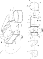
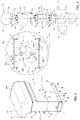
Figure 1 is a perspective view, with parts removed for clarity, of an air conditioning device made according to the present invention and according to a first operative configuration; -
Figure 2 is an exploded schematic side view, with parts removed for clarity, of the conditioning device ofFigure 1 ; -
Figure 3 is a perspective view, with parts removed for clarity, of the air conditioning device in a second operative configuration; -
Figure 4 is an exploded schematic side view, with parts removed for clarity, of the conditioning device ofFigure 3 ; -
Figure 5 is a perspective view, with parts removed for clarity, of the air conditioning device according to a third operative configuration; and -
Figure 6 is an exploded schematic side view, with parts removed for clarity, of the conditioning device ofFigure 5 . - With reference to the attached figures, a device for conditioning the air present in an
inner room 2 of a means of transport (not illustrated) is referred to as a whole with 1. - In particular, the present invention is advantageously but not exclusively applied for conditioning a passenger compartment 2 (partially and schematically illustrated in
Figure 1 ) of a motor vehicle or a commercial transport means or work vehicle, to which the present description will refer without losing generality. - The device 1 comprises:
- a fluidic circuit (known in itself and not illustrated) configured to circulate a first operative fluid, e.g. Freon® or similar;
- air conditioning means 3 (known in itself and illustrated only schematically in the attached figures) cooperating, in use, with the fluidic circuit to condition the first operative fluid and, through it, the air present in the
passenger compartment 2; and - a
radiator mass 4 configured to receive a second operative fluid, preferably water heated by the engine or other equipment of the means of transport, and defining a heat exchange interface between the second operative fluid received and the air that laps/crosses, in use, theradiator mass 4. - In detail, the conditioning means 3 comprise a condenser, an evaporator, a dryer, an accumulator and, preferably, other components such as a compressor, an expansion valve, etc. (not illustrated), the operation of which is known in itself and is not herein disclosed.
- In greater detail, the aforementioned components define, together with the fluidic circuit, a refrigeration circuit for conditioning (cooling) the air present in the
passenger compartment 2. - Preferably, the
radiator mass 4 comprises a set of heat exchange fins (known and not illustrated) defining the aforementioned interface and receiving, in a known and not detailed manner, the second operative fluid, preferably heated water. In particular, theradiator mass 4 comprises aninlet 4b for the second operative fluid and anoutlet 4a for the second operative fluid that has exchanged heat. In use, the fins are lapped/crossed by the air in order to release the heat carried by the second operative fluid and thus heat thepassenger compartment 2. - In view of the foregoing, the conditioning means 3 are configured to cool the air present in
passenger compartment 2 and theradiator mass 4 is configured to heat the air present inpassenger compartment 2. - Conveniently, the conditioning means 3 and the
radiator mass 4 are selectively switchable on and off to heat or cool the air in thepassenger compartment 2, depending on certain ambient conditions (summer or winter) or depending on the desired temperature inside thepassenger compartment 2. - In other words, when the conditioning means 3 is on,
radiator mass 4 is off, and vice versa. - Alternatively, the conditioning means 3 and the
radiator mass 4 may be activated simultaneously for conditioning in a combined way the air of thepassenger compartment 2. - According to a first aspect of the present invention, the device 1 is of the modular type and the conditioning means 3 and the
radiator mass 4 are housed in respective,separate casings - In particular, the device 1 comprises:
- a
first casing 5 housing the conditioning means 3, defining a first module M1 of the device 1, having a first inlet opening 5a for the air to be conditioned (preferably to be cooled) and a first outlet opening 5b for the conditioned air (preferably cooled), preferably arranged on opposite sides of thefirst casing 5 itself, and including afirst connection interface 6 arranged at the first outlet opening 5b; and - a
second casing 7 housing theradiator mass 4, defining a second module M2 of the device 1, having a second inlet opening 7a for the air (to be heated) and a second outlet opening 7b for the (heated) air, preferably arranged on opposite sides of thesecond casing 7 itself, and including asecond connection interface 8 arranged at the second inlet opening 7a. - According to the invention, the
first interface 6 may be coupled to thesecond interface 8 by means of releasable fastening means 10, either directly or with the interposition of parts (illustrated inFigure 4 ). - In the non-limiting example described and illustrated herein, the first connection interface is defined by a
connection flange 6 carried by thefirst casing 5 at the first outlet opening 5b, and the second connection interface is defined by aconnection flange 8 carried by thesecond casing 7 at the second inlet opening 7a. - Preferably, the fastening means 10 are defined by threaded members, such as screws and bolts, rivets, clamps, or the like, configured to determine the releasable coupling of the
flange 6 with theflange 8 and, therefore, of the first module M1 with the second module M2. - Therefore, thanks to the configuration described above, the
first casing 5 and thesecond casing 7, i.e. the first module M1 and the second module M2 are connected in series and in a releasable manner, so that they can be coupled together directly or with interposition of parts. - In other words, the
radiator mass 4 may be releasably coupled in series with the conditioning means 3, so that it can be coupled with it directly or with the interposition of parts. - Preferably, the
radiator mass 4 may be selected from a plurality of configurations (illustrated in a dotted line inFigures 2 ,4 and6 ) or types that differ from each other only with regard to the arrangement of outlet opening 7b. - More precisely, the various selectable configurations of
radiator mass 4 differ from each other in the angle of the outlet opening 7b, as illustrated in the above figures. - Thus, thanks to the modularity of the device 1, the modules M1 and M2 may be releasably coupled directly to each other or with interposition of parts, and, in addition, an
appropriate radiator mass 4 may be selected depending on the desired angle of the outlet opening 7b, without having to replace and redesign the entire device 1. - Appropriately, the
first casing 5 further houses the fluidic circuit. - As is well known in the field, condensation is not unlikely to form, in use, inside the evaporator of the conditioning means 3, mainly due to the temperature difference between the evaporator and the air to be conditioned lapping it. Such temperature difference causes the condensation of the moisture housed in the air to be conditioned.
- In order to evacuate the condensation produced, the device 1 comprises condensation collection means 11 fluidically connectable to the conditioning means 3 to receive the condensation produced, in use, by the latter, or rather by the aforementioned evaporator.
- According to an important aspect of the present invention, the device 1 is selectively available in:
- a position horizontal (
Figures 1 and 2 ) with respect to a platform of the means of transport parallel to the ground on which the means of transport advances, in use; and in - a position inclined (
Figures 3 to 6 ) with respect to said horizontal position, in particular a vertical position with respect to said platform. - In particular, the platform could be defined by the platform of the wheels (or rails) of the means of transport).
- More specifically, the aforesaid positions are horizontal and inclined (vertical) relative to the force of gravity, when the means of transport advances on a level surface.
- According to a further aspect of the present invention, the device 1 comprises a
third casing 12 housing themeans 11 for collecting the condensation produced, in use, by the conditioning means 3, defining a third module M3 of the device 1 and configured to be crossed by an air flow F in forced ventilation. - Still according to such aspect of the invention, the
third casing 12 is interposed between thefirst casing 5 and thesecond casing 7 when the device 1 is placed, in use, in said inclined position, in particular in a vertical position, and the aforesaid air flow F is directed, in forced ventilation, downwards relative to a horizontal direction with respect to the aforesaid plane (Figures 3 and 4 ). - Still according to such aspect of the invention, the
third casing 12 is arranged upstream of the first inlet opening 5a, relative to the direction of the air flow F, when the device 1 is placed, in use, in said inclined position relative to the horizontal direction, in particular in a vertical position, and the air flow F is directed, in forced ventilation, upwards relative to said horizontal direction (Figures 5 and 6 ). - Conveniently, the
third casing 12 has twoopenings 12a for the passage of the air flow arranged at opposite walls of thethird casing 12 transverse to the direction of the air flow. In addition, thethird casing 12 comprises athird connection interface 13 and afourth connection interface 14 each one arranged at one of theopenings 12a. - Preferably, the
third interface 13 and thefourth interface 14 are also defined by respective connection flanges. - As visible in
Figure 4 , in the case of the inclined arrangement with a downward-directed air flow F, thethird interface 13 is releasably coupled to thefirst interface 6 and thefourth interface 14 is releasably coupled to thesecond interface 8, e.g. by means of the aforementioned releasable fastening means 10. - Thereby, the
third casing 12 is interposed between thefirst casing 5 and thesecond casing 7. Thus, in such a configuration, thefirst casing 5 and thesecond casing 7 are connected to each other in a releasable manner by interposition of parts, where these parts are defined by thethird casing 12 and by the collection means 11. - By contrast, as visible in
Figure 6 , in the case of the inclined arrangement with upwardly-directed air flow F, thethird interface 13 is releasably coupled with afifth interface 15 of thefirst casing 5 arranged at theinlet opening 5a, while thefourth interface 14 is free or releasably couplable to a component described below for receiving the air flow F in forced ventilation. - Thereby, the
third casing 12 is placed upstream of theinlet opening 5a. - In view of the foregoing, depending on the orientation of the air flow F, and thanks to the modularity of the device 1, it is possible to arrange the
third casing 12, and therefore the collection means 11, in the optimal position for collecting the condensation produced, within thefirst casing 5 by the conditioning means 3 and thus avoid such condensation from escaping from theoutlet opening 7b (in the case of the inclined arrangement with air flow F directed downwards) or from theinlet opening 5a (in the case of the inclined arrangement with the air flow F directed upwards). In fact, in such inclined and non-horizontal arrangements, the condensation produced tends to fall downwards under the action of gravity and, therefore, to drip out of thefirst casing 5 downwards. Thanks to the modularity of the device 1, it is therefore sufficient to reorganise the positioning of modules M1, M2, and M3, and thus ofcasings - Advantageously, when the device 1 is arranged in said horizontal position, the
first casing 5 is connected to thesecond casing 7 directly without interposition of parts by releasable coupling of the flange 6 (i.e. the first interface) with the flange 8 (i.e. the second interface). This operative condition is illustrated inFigures 1 and 2 . - Therefore, in such a configuration, the
third casing 12 and, therefore, the third module M3 is not provided. - Suitably, the
first casing 5 comprisesducts 16 arranged at one of the walls constituting thefirst casing 5, in particular the lower wall when it is arranged in a horizontal position, and placing the interior of thefirst casing 5 in fluidic communication with the outside, in order to collect the condensation produced by the conditioning means 3 and discharge it outside thefirst casing 5. - In detail, in this specific operative condition in which the device 1 is placed in a horizontal position, the
ducts 16 receive, by gravity, the condensation produced by the conditioning means 3 and convey it outside thefirst casing 5. - Once again, thanks to its modularity, the device 1 is highly flexible and adaptable to construction and project requirements. In this case, it is in fact possible to omit the
third casing 12 or third module M3 without having to redesign the entire device 1. - Thus, thanks to the modularity of the device 1, it is possible to appropriately recombine the modules M1, M2, M3 constituting the device 1 itself according to the different operative and construction requirements, which most often depend on the spatial configuration of the means of transport on which the device 1 is to be installed.
- As shown in
Figures 2 ,4 and6 , thefirst casing 5 has the aforementionedfifth connection interface 15 arranged at theinlet opening 5a. - Preferably, the
fifth interface 15 is defined by a connection flange of the type described above. - Conveniently, the device 1 comprises:
- forced ventilation means 18, for example an electric fan, configured to convey and direct the aforesaid air flow F towards the
inlet opening 5a and, through thefirst casing 5, towards theoutlet opening 5b and, then, towards the inlet opening 7a of the second casing; and - a
fourth casing 19 housing the forced ventilation means 18, defining a fourth module M4 of the device 1 and having a sixth connection interface 20 (also preferably defined by a connection flange of the type described above). - According to one aspect of the present invention, the
fifth interface 15 may be coupled to thesixth interface 20 by means of the aforementioned releasable fastening means 10, either directly or by interposition of parts. - In particular, the
fourth casing 19, i.e. the fourth module M4 is suitably arranged upstream of every other casing or module of the device 1, so as to direct the air flow F towards all the existing casings and modules, so that the air flow F passes through them in succession. - As visible in
Figure 4 , in the case of the inclined arrangement with downward-directed air flow F, thefourth casing 19 is coupled in a releasable manner directly to thefirst casing 5, i.e. thesixth interface 20 is coupled in a releasable manner directly to thefifth interface 15, e.g. by means of the fastening means 10, and thus without interposition of parts. - As visible in
Figure 2 , even in the case of the horizontal arrangement, thefourth casing 19 is coupled in a releasable manner directly to thefirst casing 5, and thus without interposition of parts. - In contrast, as visible in
Figure 6 , in the case of the inclined arrangement with upward-directed air flow F, thefourth casing 19 is releasably coupled to thethird casing 12, i.e. thesixth interface 20 is coupled directly to thefourth interface 14, e.g. by means of fastening means 10. Therefore, in this case the sixth interface 20 (the fourth casing 19) is coupled to the fifth interface 15 (the first casing 5) with interposition of parts, these parts being defined by thethird casing 12. - In this case also, thanks to the modularity of the device 1, the modules M1, M2, M3 and M4 of the device can be rearranged according to operative and construction requirements.
- Advantageously, the collection means 11 comprise at least two
inclined surfaces 21 for collecting the condensation produced, in use, by the conditioning means 3, the collection surfaces 21 extending cantilevered from oppositeinner walls 12b of thethird casing 12 towards the interior of thethird casing 12 itself. - In detail, each collection surface is defined by a
chute 21 configured to receive (in particular by gravity) the moisture within the air flow F condensed by the conditioning means 3, and extending cantilevered from the correspondinginner wall 12b towards the oppositeinner wall 12b. - In greater detail, the
inner walls 12b are contiguous with the walls on which theopenings 12a are obtained. In practice, theinner walls 12b are essentially parallel to the advancement direction of the air flow F within thethird casing 12. - According to one aspect of the invention, the
chutes 21, i.e. the collection surfaces, are arranged staggered within thethird casing 12 in such a way that the air flow F performs an S-shaped path therein. - More precisely, the
chutes 21 are staggered with respect to the forward direction of the air flow F within thethird casing 12. - In addition, each
chute 21 has, at its free end, abasin 22 for collecting the condensed moisture fluidically connectable to arelative outlet duct 23 configured to convey the condensed moisture out of thethird casing 12. - In the light of the foregoing, an
upper chute 21 and alower chute 21 may be identified, relative to the direction of the force of gravity. - Thanks to this configuration, effective collection of condensation is ensured at essentially any inclination of the device 1, e.g. in an arrangement thereof inclined at 30° with respect to the vertical direction (relative to the force of gravity). In fact, the presence of the two
chutes 21 arranged staggered and extending atopposite walls 12b ensures the complete collection of condensed moisture by theupper chute 21 and, when the device 1 is arranged inclined beyond a certain angle, by thelower chute 21. - Advantageously, the fourth module M4, i.e. the forced ventilation means 18, is selectable from a plurality of types differing from each other and having the same
sixth interface 20 that can be selectively coupled to thefifth interface 15, either directly or with interposition of parts, as described above. - After examining the characteristics of the device 1 made according to the present invention, the advantages it allows to obtain are clear.
- In particular, thanks to the modularity of the device 1, the modules M1 and M2 may be releasably coupled directly to each other or with interposition of parts, and, in addition, an
appropriate radiator mass 4 may be selected depending on the desired angle of theoutlet opening 7b, without having to replace and redesign the entire device 1. - Furthermore, thanks to the modularity of the device 1, it is possible to arrange the
third casing 12, and therefore the collection means 11, in the optimal position for collecting the condensation produced, within thefirst casing 5, by the conditioning means 3 and thus to avoid the leakage of this condensation from theoutlet opening 7b (in the case of the inclined arrangement with air flow F directed downwards) or from theinlet opening 5a (in the case of the inclined arrangement with an air flow F directed upwards). - In addition, thanks to the modularity of the device 1, the modules M1, M2, M3 and M4 of the device may be rearranged according to operative and construction requirements.
- In the light of the foregoing, thanks to the modularity of the device 1, it is therefore possible to appropriately recombine the modules M1, M2, M3 constituting the device 1 itself according to the different operative and construction requirements, which most often depend on the spatial configuration of the means of transport on which device 1 is to be installed.
- Thus, the device 1 defines an HVAC unit of the modular type, i.e. an HVAC unit not defined by a single compact and integrated casing housing all the components organised in a static and unchangeable configuration except by means of a redesign, rearrangement, reorganisation or non-immediate reassembly of the parts, as is possible in the case of the device 1 made according to the present invention.
- Finally, thanks to the presence and special arrangement and configuration of the
chutes 21 of the collection means 11, effective collection of the condensation is ensured in essentially any inclination of the device 1. - It is clear that the device 1 described and shown herein may be subject to modifications and variations without departing from the scope of protection defined by the claims.
- In particular, collection means 11 of the type described above, i.e. including
chutes 21 arranged staggered and extending cantilevered from opposite walls, could be implemented in an integrated conditioning device of the non-modular type that needs to be arranged at an angle to the vertical direction in order to effectively collect the condensation produced. - In other words, collection means 11 of the type described above, i.e. comprising the
aforesaid chutes 21 could be implemented in an air conditioning device merely comprising: the aforementioned fluidic circuit configured to circulate the operative fluid, the conditioning means 3, and the collection means 11 comprising acasing 12 configured to be crossed by the air flow and at least twoinclined surfaces 21 for collecting the condensation produced, in use, by the conditioning means 3, the collection surfaces 21 extending cantilevered from opposinginner walls 12b of thecasing 12 towards the interior of thecasing 12, the collection surfaces (21) being arranged staggered within thecasing 12 so that the air flow completes, therein, an S-shaped path. Preferably, each collection surface is defined by anaforesaid chute 21, which is configured to receive condensed moisture from the conditioning means 3, extends cantilevered from the relativeinner wall 12b towards the oppositeinner wall 12b and has, at its free end, abasin 22 for collecting condensed moisture fluidically connectable to arelative outlet duct 23 configured to convey the condensed moisture out of thecasing 12.
Claims (8)
- Air conditioning device (1) for conditioning the air present in an inner environment (2) of a means of transport, said device (1) comprising:- a fluidic circuit configured to circulate a first operative fluid;- conditioning means (3) cooperating, in use, with the circuit to condition the first operative fluid and, through this, the air present in the inner environment (2) of the means of transport; and- a radiator mass (4) configured to receive a second operative fluid and defining a heat exchange interface between the second operative fluid received and the air that laps/crosses, in use, the radiator mass (4);wherein the air conditioning device (1) comprises:
wherein the air conditioning device (1) is of modular type and the air conditioning means (3) and the radiator mass (4) are housed in respective, separate casings (5, 7) connectable in a releasable manner to one another directly or with interposition of parts;- a first casing (5) housing the conditioning means (3), defining a first module (M1) of the device (1), having a first inlet opening (5a) for the air to be conditioned and a first outlet opening (5b) for the conditioned air and including a first connection interface (6) arranged at the first outlet opening (5b); and- a second casing (7) housing the radiator mass (4), defining a second module (M2) of the device (1), having a second inlet opening (7a) for the air and a second outlet opening (7b) for the air, and including a second connection interface (8) arranged at the second inlet opening (7a);
and wherein said first interface (6) is couplable to said second connection interface (8) by means of releasable fastening means (10), directly or with interposition of parts. - Device as claimed in claim 1, wherein the device (1) is selectively arrangeable in:- a position horizontal with respect to a platform of the means of transport parallel to the ground on which the means of transport advances, in use; and in- a position inclined with respect to said horizontal position, in particular a vertical position with respect to said platform.
- Device as claimed in claim 2, wherein, when the device (1) is arranged, in use, in said position horizontal with respect to said platform, the first casing (5) is connected to the second casing (7) directly without interposition of parts by releasable coupling of the first connection interface (6) with the second connection interface (8).
- Device as claimed in claim 2, and comprising a third casing (12) housing collection means (11) for collecting the condensation produced, in use, by the conditioning means (3), defining a third module (M3) of the device and configured to be crossed by an air flow in forced ventilation;
and wherein the third casing (12) is interposed in coupling between the first casing (5) and the second casing (7) when the device (1) is arranged, in use, in said position inclined with respect to said horizontal position and the air flow is directed, in forced ventilation, downwards with respect to a direction horizontal relative to said platform. - Device as claimed in claim 2, and comprising a third casing (12) housing collection means (11) for collecting the condensation produced, in use, by the conditioning means (3), defining a third module (M3) of the device (1) and configured to be crossed by an air flow in forced ventilation;
and wherein the third casing (12) is arranged upstream of the first inlet opening (5a), relative to the direction of the air flow, when the device (1) is arranged, in use, in said position inclined with respect to said horizontal position and the air flow is directed, in forced ventilation, upwards with respect to a direction horizontal relative to said platform. - Device as claimed in claim 4 or 5, wherein said collection means (11) comprise at least two inclined collection surfaces (21) for collecting the condensation produced, in use, by the conditioning means (3), the collection surfaces (21) extending cantilevered from opposite inner walls (12b) of the third casing (12) towards the interior of the third casing (12) itself,
and wherein the collection surfaces (21) are arranged staggered inside the third casing (12) so that the air flow defines an S-shaped path therein. - Device as claimed in claim 6, wherein each collection surface is defined by a chute (21) configured to receive condensed moisture from the conditioning means (3), projecting from the relative inner wall (12b) towards the opposite inner wall (12b) and having, at its free end, a basin (22) for collecting the condensed moisture fluidically connectable to a relative outlet duct (23) configured to convey the condensed moisture out of the third casing (12).
- Device as claimed in any one of claims 1 to 6, wherein the first casing (5) has a third connection interface (15) arranged at the first inlet opening (5a);wherein the device (1) comprises:- forced ventilation means (18) configured to convey and direct an air flow towards the first inlet opening (5a) and, through the first casing (5), towards the first outlet opening (5b) and, then, towards the second inlet opening (7a); and- a fourth casing (19) housing the forced ventilation means (18), defining a fourth module (M4) of the device (1) and having a fourth connection interface (20);said third connection interface (15) being couplable to said fourth connection interface (20) by means of releasable fastening means (10), directly or with interposition of parts.
Applications Claiming Priority (1)
| Application Number | Priority Date | Filing Date | Title |
|---|---|---|---|
| IT102021000017069A IT202100017069A1 (en) | 2021-06-29 | 2021-06-29 | AIR CONDITIONING DEVICE |
Publications (3)
| Publication Number | Publication Date |
|---|---|
| EP4112342A1 true EP4112342A1 (en) | 2023-01-04 |
| EP4112342C0 EP4112342C0 (en) | 2024-01-24 |
| EP4112342B1 EP4112342B1 (en) | 2024-01-24 |
Family
ID=77802118
Family Applications (1)
| Application Number | Title | Priority Date | Filing Date |
|---|---|---|---|
| EP22181485.8A Active EP4112342B1 (en) | 2021-06-29 | 2022-06-28 | Air conditioning device |
Country Status (2)
| Country | Link |
|---|---|
| EP (1) | EP4112342B1 (en) |
| IT (1) | IT202100017069A1 (en) |
Citations (3)
| Publication number | Priority date | Publication date | Assignee | Title |
|---|---|---|---|---|
| FR2274465A1 (en) | 1974-06-13 | 1976-01-09 | Caterpillar Tractor Co | Air conditioning system for construction vehicle - is in modular form with combined intake blower and controls for distribution blowers |
| DE19645776A1 (en) | 1995-11-09 | 1997-05-15 | Zexel Corp | Air conditioning unit esp. for vehicles |
| DE102007023249A1 (en) | 2007-05-18 | 2008-11-20 | Thermo King Deutschland Gmbh | Roof-mounted air conditioning system for omnibus or tram is a pre-assembled modular unit |
-
2021
- 2021-06-29 IT IT102021000017069A patent/IT202100017069A1/en unknown
-
2022
- 2022-06-28 EP EP22181485.8A patent/EP4112342B1/en active Active
Patent Citations (3)
| Publication number | Priority date | Publication date | Assignee | Title |
|---|---|---|---|---|
| FR2274465A1 (en) | 1974-06-13 | 1976-01-09 | Caterpillar Tractor Co | Air conditioning system for construction vehicle - is in modular form with combined intake blower and controls for distribution blowers |
| DE19645776A1 (en) | 1995-11-09 | 1997-05-15 | Zexel Corp | Air conditioning unit esp. for vehicles |
| DE102007023249A1 (en) | 2007-05-18 | 2008-11-20 | Thermo King Deutschland Gmbh | Roof-mounted air conditioning system for omnibus or tram is a pre-assembled modular unit |
Also Published As
| Publication number | Publication date |
|---|---|
| EP4112342C0 (en) | 2024-01-24 |
| IT202100017069A1 (en) | 2022-12-29 |
| EP4112342B1 (en) | 2024-01-24 |
Similar Documents
| Publication | Publication Date | Title |
|---|---|---|
| KR200342074Y1 (en) | Built-in type outdoor unit for airconditioner | |
| CN109661316B (en) | Vehicle thermal management system | |
| US9151507B2 (en) | Air conditioner | |
| JP5768205B2 (en) | Vehicle cabin air conditioning system and module including the system | |
| CN104737361B (en) | Battery temperature adjustment unit and carry the vehicle of the unit | |
| KR101397217B1 (en) | Heat source unit | |
| CA2781366C (en) | Modular heating, ventilating, air conditioning, and refrigeration systems and methods | |
| US7971448B2 (en) | Air conditioner | |
| US20170130975A1 (en) | Climate Control Outdoor Unit with Inverter Cooling | |
| US20100011803A1 (en) | Horizontal discharge air conditioning unit | |
| EP2400230B1 (en) | Indoor unit of air conditioner | |
| US20050126216A1 (en) | Self-contained flush-mount bulkhead air conditioning unit with novel evaporator/blower assembly housing | |
| CN107635803B (en) | Condenser unit for top mounted air conditioning system | |
| EP4112342B1 (en) | Air conditioning device | |
| US11982462B2 (en) | Air conditioner | |
| CN100594343C (en) | Condensation water drainage configuration used for evaporator unit | |
| EP2072299A2 (en) | Transport refrigeration apparatus | |
| KR102174514B1 (en) | Air conditioning system | |
| CN101283228B (en) | Condensed water drain pan for evaporator unit | |
| JP7835613B2 (en) | Duct structure and air conditioning system equipped therewith | |
| KR20190115858A (en) | Hybrid air conditioning system | |
| RU37343U1 (en) | PASSENGER WAGON AIR CONDITIONING SYSTEM | |
| KR20230036780A (en) | Positive pressure cooling system for combat vehicles | |
| KR20250022196A (en) | Pre-subcooler for condenser | |
| KR20030040338A (en) | Front suction and discharge type outdoor unit for air-conditioner |
Legal Events
| Date | Code | Title | Description |
|---|---|---|---|
| PUAI | Public reference made under article 153(3) epc to a published international application that has entered the european phase |
Free format text: ORIGINAL CODE: 0009012 |
|
| STAA | Information on the status of an ep patent application or granted ep patent |
Free format text: STATUS: THE APPLICATION HAS BEEN PUBLISHED |
|
| AK | Designated contracting states |
Kind code of ref document: A1 Designated state(s): AL AT BE BG CH CY CZ DE DK EE ES FI FR GB GR HR HU IE IS IT LI LT LU LV MC MK MT NL NO PL PT RO RS SE SI SK SM TR |
|
| STAA | Information on the status of an ep patent application or granted ep patent |
Free format text: STATUS: REQUEST FOR EXAMINATION WAS MADE |
|
| 17P | Request for examination filed |
Effective date: 20230622 |
|
| RBV | Designated contracting states (corrected) |
Designated state(s): AL AT BE BG CH CY CZ DE DK EE ES FI FR GB GR HR HU IE IS IT LI LT LU LV MC MK MT NL NO PL PT RO RS SE SI SK SM TR |
|
| GRAP | Despatch of communication of intention to grant a patent |
Free format text: ORIGINAL CODE: EPIDOSNIGR1 |
|
| STAA | Information on the status of an ep patent application or granted ep patent |
Free format text: STATUS: GRANT OF PATENT IS INTENDED |
|
| INTG | Intention to grant announced |
Effective date: 20230811 |
|
| GRAS | Grant fee paid |
Free format text: ORIGINAL CODE: EPIDOSNIGR3 |
|
| GRAA | (expected) grant |
Free format text: ORIGINAL CODE: 0009210 |
|
| STAA | Information on the status of an ep patent application or granted ep patent |
Free format text: STATUS: THE PATENT HAS BEEN GRANTED |
|
| AK | Designated contracting states |
Kind code of ref document: B1 Designated state(s): AL AT BE BG CH CY CZ DE DK EE ES FI FR GB GR HR HU IE IS IT LI LT LU LV MC MK MT NL NO PL PT RO RS SE SI SK SM TR |
|
| REG | Reference to a national code |
Ref country code: GB Ref legal event code: FG4D |
|
| REG | Reference to a national code |
Ref country code: CH Ref legal event code: EP |
|
| REG | Reference to a national code |
Ref country code: DE Ref legal event code: R096 Ref document number: 602022001678 Country of ref document: DE |
|
| REG | Reference to a national code |
Ref country code: IE Ref legal event code: FG4D |
|
| U01 | Request for unitary effect filed |
Effective date: 20240209 |
|
| U07 | Unitary effect registered |
Designated state(s): AT BE BG DE DK EE FI FR IT LT LU LV MT NL PT SE SI Effective date: 20240220 |
|
| PG25 | Lapsed in a contracting state [announced via postgrant information from national office to epo] |
Ref country code: IS Free format text: LAPSE BECAUSE OF FAILURE TO SUBMIT A TRANSLATION OF THE DESCRIPTION OR TO PAY THE FEE WITHIN THE PRESCRIBED TIME-LIMIT Effective date: 20240524 |
|
| PG25 | Lapsed in a contracting state [announced via postgrant information from national office to epo] |
Ref country code: GR Free format text: LAPSE BECAUSE OF FAILURE TO SUBMIT A TRANSLATION OF THE DESCRIPTION OR TO PAY THE FEE WITHIN THE PRESCRIBED TIME-LIMIT Effective date: 20240425 |
|
| PG25 | Lapsed in a contracting state [announced via postgrant information from national office to epo] |
Ref country code: RS Free format text: LAPSE BECAUSE OF FAILURE TO SUBMIT A TRANSLATION OF THE DESCRIPTION OR TO PAY THE FEE WITHIN THE PRESCRIBED TIME-LIMIT Effective date: 20240424 Ref country code: HR Free format text: LAPSE BECAUSE OF FAILURE TO SUBMIT A TRANSLATION OF THE DESCRIPTION OR TO PAY THE FEE WITHIN THE PRESCRIBED TIME-LIMIT Effective date: 20240124 |
|
| PG25 | Lapsed in a contracting state [announced via postgrant information from national office to epo] |
Ref country code: ES Free format text: LAPSE BECAUSE OF FAILURE TO SUBMIT A TRANSLATION OF THE DESCRIPTION OR TO PAY THE FEE WITHIN THE PRESCRIBED TIME-LIMIT Effective date: 20240124 |
|
| U20 | Renewal fee for the european patent with unitary effect paid |
Year of fee payment: 3 Effective date: 20240618 |
|
| PG25 | Lapsed in a contracting state [announced via postgrant information from national office to epo] |
Ref country code: RS Free format text: LAPSE BECAUSE OF FAILURE TO SUBMIT A TRANSLATION OF THE DESCRIPTION OR TO PAY THE FEE WITHIN THE PRESCRIBED TIME-LIMIT Effective date: 20240424 Ref country code: NO Free format text: LAPSE BECAUSE OF FAILURE TO SUBMIT A TRANSLATION OF THE DESCRIPTION OR TO PAY THE FEE WITHIN THE PRESCRIBED TIME-LIMIT Effective date: 20240424 Ref country code: IS Free format text: LAPSE BECAUSE OF FAILURE TO SUBMIT A TRANSLATION OF THE DESCRIPTION OR TO PAY THE FEE WITHIN THE PRESCRIBED TIME-LIMIT Effective date: 20240524 Ref country code: HR Free format text: LAPSE BECAUSE OF FAILURE TO SUBMIT A TRANSLATION OF THE DESCRIPTION OR TO PAY THE FEE WITHIN THE PRESCRIBED TIME-LIMIT Effective date: 20240124 Ref country code: GR Free format text: LAPSE BECAUSE OF FAILURE TO SUBMIT A TRANSLATION OF THE DESCRIPTION OR TO PAY THE FEE WITHIN THE PRESCRIBED TIME-LIMIT Effective date: 20240425 Ref country code: ES Free format text: LAPSE BECAUSE OF FAILURE TO SUBMIT A TRANSLATION OF THE DESCRIPTION OR TO PAY THE FEE WITHIN THE PRESCRIBED TIME-LIMIT Effective date: 20240124 |
|
| PG25 | Lapsed in a contracting state [announced via postgrant information from national office to epo] |
Ref country code: PL Free format text: LAPSE BECAUSE OF FAILURE TO SUBMIT A TRANSLATION OF THE DESCRIPTION OR TO PAY THE FEE WITHIN THE PRESCRIBED TIME-LIMIT Effective date: 20240124 |
|
| PG25 | Lapsed in a contracting state [announced via postgrant information from national office to epo] |
Ref country code: PL Free format text: LAPSE BECAUSE OF FAILURE TO SUBMIT A TRANSLATION OF THE DESCRIPTION OR TO PAY THE FEE WITHIN THE PRESCRIBED TIME-LIMIT Effective date: 20240124 |
|
| PG25 | Lapsed in a contracting state [announced via postgrant information from national office to epo] |
Ref country code: SM Free format text: LAPSE BECAUSE OF FAILURE TO SUBMIT A TRANSLATION OF THE DESCRIPTION OR TO PAY THE FEE WITHIN THE PRESCRIBED TIME-LIMIT Effective date: 20240124 |
|
| PG25 | Lapsed in a contracting state [announced via postgrant information from national office to epo] |
Ref country code: CZ Free format text: LAPSE BECAUSE OF FAILURE TO SUBMIT A TRANSLATION OF THE DESCRIPTION OR TO PAY THE FEE WITHIN THE PRESCRIBED TIME-LIMIT Effective date: 20240124 |
|
| REG | Reference to a national code |
Ref country code: DE Ref legal event code: R097 Ref document number: 602022001678 Country of ref document: DE |
|
| PG25 | Lapsed in a contracting state [announced via postgrant information from national office to epo] |
Ref country code: SK Free format text: LAPSE BECAUSE OF FAILURE TO SUBMIT A TRANSLATION OF THE DESCRIPTION OR TO PAY THE FEE WITHIN THE PRESCRIBED TIME-LIMIT Effective date: 20240124 |
|
| PG25 | Lapsed in a contracting state [announced via postgrant information from national office to epo] |
Ref country code: SM Free format text: LAPSE BECAUSE OF FAILURE TO SUBMIT A TRANSLATION OF THE DESCRIPTION OR TO PAY THE FEE WITHIN THE PRESCRIBED TIME-LIMIT Effective date: 20240124 Ref country code: SK Free format text: LAPSE BECAUSE OF FAILURE TO SUBMIT A TRANSLATION OF THE DESCRIPTION OR TO PAY THE FEE WITHIN THE PRESCRIBED TIME-LIMIT Effective date: 20240124 Ref country code: CZ Free format text: LAPSE BECAUSE OF FAILURE TO SUBMIT A TRANSLATION OF THE DESCRIPTION OR TO PAY THE FEE WITHIN THE PRESCRIBED TIME-LIMIT Effective date: 20240124 |
|
| PLBE | No opposition filed within time limit |
Free format text: ORIGINAL CODE: 0009261 |
|
| STAA | Information on the status of an ep patent application or granted ep patent |
Free format text: STATUS: NO OPPOSITION FILED WITHIN TIME LIMIT |
|
| 26N | No opposition filed |
Effective date: 20241025 |
|
| PG25 | Lapsed in a contracting state [announced via postgrant information from national office to epo] |
Ref country code: MC Free format text: LAPSE BECAUSE OF FAILURE TO SUBMIT A TRANSLATION OF THE DESCRIPTION OR TO PAY THE FEE WITHIN THE PRESCRIBED TIME-LIMIT Effective date: 20240124 |
|
| PG25 | Lapsed in a contracting state [announced via postgrant information from national office to epo] |
Ref country code: IE Free format text: LAPSE BECAUSE OF NON-PAYMENT OF DUE FEES Effective date: 20240628 |
|
| U20 | Renewal fee for the european patent with unitary effect paid |
Year of fee payment: 4 Effective date: 20250627 |
|
| PG25 | Lapsed in a contracting state [announced via postgrant information from national office to epo] |
Ref country code: RO Free format text: LAPSE BECAUSE OF FAILURE TO SUBMIT A TRANSLATION OF THE DESCRIPTION OR TO PAY THE FEE WITHIN THE PRESCRIBED TIME-LIMIT Effective date: 20240124 |
|
| PG25 | Lapsed in a contracting state [announced via postgrant information from national office to epo] |
Ref country code: CY Free format text: LAPSE BECAUSE OF FAILURE TO SUBMIT A TRANSLATION OF THE DESCRIPTION OR TO PAY THE FEE WITHIN THE PRESCRIBED TIME-LIMIT; INVALID AB INITIO Effective date: 20220628 |
|
| REG | Reference to a national code |
Ref country code: CH Ref legal event code: H13 Free format text: ST27 STATUS EVENT CODE: U-0-0-H10-H13 (AS PROVIDED BY THE NATIONAL OFFICE) Effective date: 20260127 |
|
| PG25 | Lapsed in a contracting state [announced via postgrant information from national office to epo] |
Ref country code: HU Free format text: LAPSE BECAUSE OF FAILURE TO SUBMIT A TRANSLATION OF THE DESCRIPTION OR TO PAY THE FEE WITHIN THE PRESCRIBED TIME-LIMIT; INVALID AB INITIO Effective date: 20220628 |
|
| PG25 | Lapsed in a contracting state [announced via postgrant information from national office to epo] |
Ref country code: CH Free format text: LAPSE BECAUSE OF NON-PAYMENT OF DUE FEES Effective date: 20250630 |