EP4112292A1 - Support sheet, flexible display screen and electronic device - Google Patents
Support sheet, flexible display screen and electronic device Download PDFInfo
- Publication number
- EP4112292A1 EP4112292A1 EP22181412.2A EP22181412A EP4112292A1 EP 4112292 A1 EP4112292 A1 EP 4112292A1 EP 22181412 A EP22181412 A EP 22181412A EP 4112292 A1 EP4112292 A1 EP 4112292A1
- Authority
- EP
- European Patent Office
- Prior art keywords
- carbon fiber
- fiber substrate
- support sheet
- flexible display
- substrate layer
- Prior art date
- Legal status (The legal status is an assumption and is not a legal conclusion. Google has not performed a legal analysis and makes no representation as to the accuracy of the status listed.)
- Withdrawn
Links
Images



Classifications
-
- H—ELECTRICITY
- H04—ELECTRIC COMMUNICATION TECHNIQUE
- H04M—TELEPHONIC COMMUNICATION
- H04M1/00—Substation equipment, e.g. for use by subscribers
- H04M1/02—Constructional features of telephone sets
- H04M1/0202—Portable telephone sets, e.g. cordless phones, mobile phones or bar type handsets
- H04M1/026—Details of the structure or mounting of specific components
- H04M1/0266—Details of the structure or mounting of specific components for a display module assembly
- H04M1/0268—Details of the structure or mounting of specific components for a display module assembly including a flexible display panel
-
- B—PERFORMING OPERATIONS; TRANSPORTING
- B32—LAYERED PRODUCTS
- B32B—LAYERED PRODUCTS, i.e. PRODUCTS BUILT-UP OF STRATA OF FLAT OR NON-FLAT, e.g. CELLULAR OR HONEYCOMB, FORM
- B32B3/00—Layered products comprising a layer with external or internal discontinuities or unevennesses, or a layer of non-planar shape; Layered products comprising a layer having particular features of form
- B32B3/02—Layered products comprising a layer with external or internal discontinuities or unevennesses, or a layer of non-planar shape; Layered products comprising a layer having particular features of form characterised by features of form at particular places, e.g. in edge regions
- B32B3/04—Layered products comprising a layer with external or internal discontinuities or unevennesses, or a layer of non-planar shape; Layered products comprising a layer having particular features of form characterised by features of form at particular places, e.g. in edge regions characterised by at least one layer folded at the edge, e.g. over another layer ; characterised by at least one layer enveloping or enclosing a material
-
- B—PERFORMING OPERATIONS; TRANSPORTING
- B32—LAYERED PRODUCTS
- B32B—LAYERED PRODUCTS, i.e. PRODUCTS BUILT-UP OF STRATA OF FLAT OR NON-FLAT, e.g. CELLULAR OR HONEYCOMB, FORM
- B32B15/00—Layered products comprising a layer of metal
- B32B15/14—Layered products comprising a layer of metal next to a fibrous or filamentary layer
-
- B—PERFORMING OPERATIONS; TRANSPORTING
- B32—LAYERED PRODUCTS
- B32B—LAYERED PRODUCTS, i.e. PRODUCTS BUILT-UP OF STRATA OF FLAT OR NON-FLAT, e.g. CELLULAR OR HONEYCOMB, FORM
- B32B15/00—Layered products comprising a layer of metal
- B32B15/20—Layered products comprising a layer of metal comprising aluminium or copper
-
- B—PERFORMING OPERATIONS; TRANSPORTING
- B32—LAYERED PRODUCTS
- B32B—LAYERED PRODUCTS, i.e. PRODUCTS BUILT-UP OF STRATA OF FLAT OR NON-FLAT, e.g. CELLULAR OR HONEYCOMB, FORM
- B32B3/00—Layered products comprising a layer with external or internal discontinuities or unevennesses, or a layer of non-planar shape; Layered products comprising a layer having particular features of form
- B32B3/02—Layered products comprising a layer with external or internal discontinuities or unevennesses, or a layer of non-planar shape; Layered products comprising a layer having particular features of form characterised by features of form at particular places, e.g. in edge regions
- B32B3/06—Layered products comprising a layer with external or internal discontinuities or unevennesses, or a layer of non-planar shape; Layered products comprising a layer having particular features of form characterised by features of form at particular places, e.g. in edge regions for securing layers together; for attaching the product to another member, e.g. to a support, or to another product, e.g. groove/tongue, interlocking
-
- B—PERFORMING OPERATIONS; TRANSPORTING
- B32—LAYERED PRODUCTS
- B32B—LAYERED PRODUCTS, i.e. PRODUCTS BUILT-UP OF STRATA OF FLAT OR NON-FLAT, e.g. CELLULAR OR HONEYCOMB, FORM
- B32B3/00—Layered products comprising a layer with external or internal discontinuities or unevennesses, or a layer of non-planar shape; Layered products comprising a layer having particular features of form
- B32B3/02—Layered products comprising a layer with external or internal discontinuities or unevennesses, or a layer of non-planar shape; Layered products comprising a layer having particular features of form characterised by features of form at particular places, e.g. in edge regions
- B32B3/08—Layered products comprising a layer with external or internal discontinuities or unevennesses, or a layer of non-planar shape; Layered products comprising a layer having particular features of form characterised by features of form at particular places, e.g. in edge regions characterised by added members at particular parts
-
- B—PERFORMING OPERATIONS; TRANSPORTING
- B32—LAYERED PRODUCTS
- B32B—LAYERED PRODUCTS, i.e. PRODUCTS BUILT-UP OF STRATA OF FLAT OR NON-FLAT, e.g. CELLULAR OR HONEYCOMB, FORM
- B32B3/00—Layered products comprising a layer with external or internal discontinuities or unevennesses, or a layer of non-planar shape; Layered products comprising a layer having particular features of form
- B32B3/26—Layered products comprising a layer with external or internal discontinuities or unevennesses, or a layer of non-planar shape; Layered products comprising a layer having particular features of form characterised by a particular shape of the outline of the cross-section of a continuous layer; characterised by a layer with cavities or internal voids ; characterised by an apertured layer
- B32B3/266—Layered products comprising a layer with external or internal discontinuities or unevennesses, or a layer of non-planar shape; Layered products comprising a layer having particular features of form characterised by a particular shape of the outline of the cross-section of a continuous layer; characterised by a layer with cavities or internal voids ; characterised by an apertured layer characterised by an apertured layer, the apertures going through the whole thickness of the layer, e.g. expanded metal, perforated layer, slit layer regular cells B32B3/12
-
- B—PERFORMING OPERATIONS; TRANSPORTING
- B32—LAYERED PRODUCTS
- B32B—LAYERED PRODUCTS, i.e. PRODUCTS BUILT-UP OF STRATA OF FLAT OR NON-FLAT, e.g. CELLULAR OR HONEYCOMB, FORM
- B32B5/00—Layered products characterised by the non- homogeneity or physical structure, i.e. comprising a fibrous, filamentary, particulate or foam layer; Layered products characterised by having a layer differing constitutionally or physically in different parts
- B32B5/02—Layered products characterised by the non- homogeneity or physical structure, i.e. comprising a fibrous, filamentary, particulate or foam layer; Layered products characterised by having a layer differing constitutionally or physically in different parts characterised by structural features of a fibrous or filamentary layer
-
- B—PERFORMING OPERATIONS; TRANSPORTING
- B32—LAYERED PRODUCTS
- B32B—LAYERED PRODUCTS, i.e. PRODUCTS BUILT-UP OF STRATA OF FLAT OR NON-FLAT, e.g. CELLULAR OR HONEYCOMB, FORM
- B32B5/00—Layered products characterised by the non- homogeneity or physical structure, i.e. comprising a fibrous, filamentary, particulate or foam layer; Layered products characterised by having a layer differing constitutionally or physically in different parts
- B32B5/02—Layered products characterised by the non- homogeneity or physical structure, i.e. comprising a fibrous, filamentary, particulate or foam layer; Layered products characterised by having a layer differing constitutionally or physically in different parts characterised by structural features of a fibrous or filamentary layer
- B32B5/024—Woven fabric
-
- B—PERFORMING OPERATIONS; TRANSPORTING
- B32—LAYERED PRODUCTS
- B32B—LAYERED PRODUCTS, i.e. PRODUCTS BUILT-UP OF STRATA OF FLAT OR NON-FLAT, e.g. CELLULAR OR HONEYCOMB, FORM
- B32B5/00—Layered products characterised by the non- homogeneity or physical structure, i.e. comprising a fibrous, filamentary, particulate or foam layer; Layered products characterised by having a layer differing constitutionally or physically in different parts
- B32B5/02—Layered products characterised by the non- homogeneity or physical structure, i.e. comprising a fibrous, filamentary, particulate or foam layer; Layered products characterised by having a layer differing constitutionally or physically in different parts characterised by structural features of a fibrous or filamentary layer
- B32B5/028—Net structure, e.g. spaced apart filaments bonded at the crossing points
-
- B—PERFORMING OPERATIONS; TRANSPORTING
- B32—LAYERED PRODUCTS
- B32B—LAYERED PRODUCTS, i.e. PRODUCTS BUILT-UP OF STRATA OF FLAT OR NON-FLAT, e.g. CELLULAR OR HONEYCOMB, FORM
- B32B5/00—Layered products characterised by the non- homogeneity or physical structure, i.e. comprising a fibrous, filamentary, particulate or foam layer; Layered products characterised by having a layer differing constitutionally or physically in different parts
- B32B5/02—Layered products characterised by the non- homogeneity or physical structure, i.e. comprising a fibrous, filamentary, particulate or foam layer; Layered products characterised by having a layer differing constitutionally or physically in different parts characterised by structural features of a fibrous or filamentary layer
- B32B5/12—Layered products characterised by the non- homogeneity or physical structure, i.e. comprising a fibrous, filamentary, particulate or foam layer; Layered products characterised by having a layer differing constitutionally or physically in different parts characterised by structural features of a fibrous or filamentary layer characterised by the relative arrangement of fibres or filaments of different layers, e.g. the fibres or filaments being parallel or perpendicular to each other
-
- B—PERFORMING OPERATIONS; TRANSPORTING
- B32—LAYERED PRODUCTS
- B32B—LAYERED PRODUCTS, i.e. PRODUCTS BUILT-UP OF STRATA OF FLAT OR NON-FLAT, e.g. CELLULAR OR HONEYCOMB, FORM
- B32B5/00—Layered products characterised by the non- homogeneity or physical structure, i.e. comprising a fibrous, filamentary, particulate or foam layer; Layered products characterised by having a layer differing constitutionally or physically in different parts
- B32B5/22—Layered products characterised by the non- homogeneity or physical structure, i.e. comprising a fibrous, filamentary, particulate or foam layer; Layered products characterised by having a layer differing constitutionally or physically in different parts characterised by the presence of two or more layers which are next to each other and are fibrous, filamentary, formed of particles or foamed
- B32B5/24—Layered products characterised by the non- homogeneity or physical structure, i.e. comprising a fibrous, filamentary, particulate or foam layer; Layered products characterised by having a layer differing constitutionally or physically in different parts characterised by the presence of two or more layers which are next to each other and are fibrous, filamentary, formed of particles or foamed one layer being a fibrous or filamentary layer
- B32B5/26—Layered products characterised by the non- homogeneity or physical structure, i.e. comprising a fibrous, filamentary, particulate or foam layer; Layered products characterised by having a layer differing constitutionally or physically in different parts characterised by the presence of two or more layers which are next to each other and are fibrous, filamentary, formed of particles or foamed one layer being a fibrous or filamentary layer another layer next to it also being fibrous or filamentary
-
- B—PERFORMING OPERATIONS; TRANSPORTING
- B32—LAYERED PRODUCTS
- B32B—LAYERED PRODUCTS, i.e. PRODUCTS BUILT-UP OF STRATA OF FLAT OR NON-FLAT, e.g. CELLULAR OR HONEYCOMB, FORM
- B32B7/00—Layered products characterised by the relation between layers; Layered products characterised by the relative orientation of features between layers, or by the relative values of a measurable parameter between layers, i.e. products comprising layers having different physical, chemical or physicochemical properties; Layered products characterised by the interconnection of layers
- B32B7/02—Physical, chemical or physicochemical properties
- B32B7/022—Mechanical properties
-
- B—PERFORMING OPERATIONS; TRANSPORTING
- B32—LAYERED PRODUCTS
- B32B—LAYERED PRODUCTS, i.e. PRODUCTS BUILT-UP OF STRATA OF FLAT OR NON-FLAT, e.g. CELLULAR OR HONEYCOMB, FORM
- B32B7/00—Layered products characterised by the relation between layers; Layered products characterised by the relative orientation of features between layers, or by the relative values of a measurable parameter between layers, i.e. products comprising layers having different physical, chemical or physicochemical properties; Layered products characterised by the interconnection of layers
- B32B7/03—Layered products characterised by the relation between layers; Layered products characterised by the relative orientation of features between layers, or by the relative values of a measurable parameter between layers, i.e. products comprising layers having different physical, chemical or physicochemical properties; Layered products characterised by the interconnection of layers with respect to the orientation of features
-
- B—PERFORMING OPERATIONS; TRANSPORTING
- B32—LAYERED PRODUCTS
- B32B—LAYERED PRODUCTS, i.e. PRODUCTS BUILT-UP OF STRATA OF FLAT OR NON-FLAT, e.g. CELLULAR OR HONEYCOMB, FORM
- B32B7/00—Layered products characterised by the relation between layers; Layered products characterised by the relative orientation of features between layers, or by the relative values of a measurable parameter between layers, i.e. products comprising layers having different physical, chemical or physicochemical properties; Layered products characterised by the interconnection of layers
- B32B7/04—Interconnection of layers
- B32B7/12—Interconnection of layers using interposed adhesives or interposed materials with bonding properties
-
- B—PERFORMING OPERATIONS; TRANSPORTING
- B32—LAYERED PRODUCTS
- B32B—LAYERED PRODUCTS, i.e. PRODUCTS BUILT-UP OF STRATA OF FLAT OR NON-FLAT, e.g. CELLULAR OR HONEYCOMB, FORM
- B32B9/00—Layered products comprising a layer of a particular substance not covered by groups B32B11/00 - B32B29/00
- B32B9/005—Layered products comprising a layer of a particular substance not covered by groups B32B11/00 - B32B29/00 comprising one layer of ceramic material, e.g. porcelain, ceramic tile
- B32B9/007—Layered products comprising a layer of a particular substance not covered by groups B32B11/00 - B32B29/00 comprising one layer of ceramic material, e.g. porcelain, ceramic tile comprising carbon, e.g. graphite, composite carbon
-
- B—PERFORMING OPERATIONS; TRANSPORTING
- B32—LAYERED PRODUCTS
- B32B—LAYERED PRODUCTS, i.e. PRODUCTS BUILT-UP OF STRATA OF FLAT OR NON-FLAT, e.g. CELLULAR OR HONEYCOMB, FORM
- B32B9/00—Layered products comprising a layer of a particular substance not covered by groups B32B11/00 - B32B29/00
- B32B9/04—Layered products comprising a layer of a particular substance not covered by groups B32B11/00 - B32B29/00 comprising such particular substance as the main or only constituent of a layer, which is next to another layer of the same or of a different material
- B32B9/047—Layered products comprising a layer of a particular substance not covered by groups B32B11/00 - B32B29/00 comprising such particular substance as the main or only constituent of a layer, which is next to another layer of the same or of a different material made of fibres or filaments
-
- B—PERFORMING OPERATIONS; TRANSPORTING
- B32—LAYERED PRODUCTS
- B32B—LAYERED PRODUCTS, i.e. PRODUCTS BUILT-UP OF STRATA OF FLAT OR NON-FLAT, e.g. CELLULAR OR HONEYCOMB, FORM
- B32B2250/00—Layers arrangement
- B32B2250/02—2 layers
-
- B—PERFORMING OPERATIONS; TRANSPORTING
- B32—LAYERED PRODUCTS
- B32B—LAYERED PRODUCTS, i.e. PRODUCTS BUILT-UP OF STRATA OF FLAT OR NON-FLAT, e.g. CELLULAR OR HONEYCOMB, FORM
- B32B2250/00—Layers arrangement
- B32B2250/03—3 layers
-
- B—PERFORMING OPERATIONS; TRANSPORTING
- B32—LAYERED PRODUCTS
- B32B—LAYERED PRODUCTS, i.e. PRODUCTS BUILT-UP OF STRATA OF FLAT OR NON-FLAT, e.g. CELLULAR OR HONEYCOMB, FORM
- B32B2250/00—Layers arrangement
- B32B2250/04—4 layers
-
- B—PERFORMING OPERATIONS; TRANSPORTING
- B32—LAYERED PRODUCTS
- B32B—LAYERED PRODUCTS, i.e. PRODUCTS BUILT-UP OF STRATA OF FLAT OR NON-FLAT, e.g. CELLULAR OR HONEYCOMB, FORM
- B32B2250/00—Layers arrangement
- B32B2250/05—5 or more layers
-
- B—PERFORMING OPERATIONS; TRANSPORTING
- B32—LAYERED PRODUCTS
- B32B—LAYERED PRODUCTS, i.e. PRODUCTS BUILT-UP OF STRATA OF FLAT OR NON-FLAT, e.g. CELLULAR OR HONEYCOMB, FORM
- B32B2250/00—Layers arrangement
- B32B2250/20—All layers being fibrous or filamentary
-
- B—PERFORMING OPERATIONS; TRANSPORTING
- B32—LAYERED PRODUCTS
- B32B—LAYERED PRODUCTS, i.e. PRODUCTS BUILT-UP OF STRATA OF FLAT OR NON-FLAT, e.g. CELLULAR OR HONEYCOMB, FORM
- B32B2255/00—Coating on the layer surface
- B32B2255/02—Coating on the layer surface on fibrous or filamentary layer
-
- B—PERFORMING OPERATIONS; TRANSPORTING
- B32—LAYERED PRODUCTS
- B32B—LAYERED PRODUCTS, i.e. PRODUCTS BUILT-UP OF STRATA OF FLAT OR NON-FLAT, e.g. CELLULAR OR HONEYCOMB, FORM
- B32B2255/00—Coating on the layer surface
- B32B2255/26—Polymeric coating
-
- B—PERFORMING OPERATIONS; TRANSPORTING
- B32—LAYERED PRODUCTS
- B32B—LAYERED PRODUCTS, i.e. PRODUCTS BUILT-UP OF STRATA OF FLAT OR NON-FLAT, e.g. CELLULAR OR HONEYCOMB, FORM
- B32B2260/00—Layered product comprising an impregnated, embedded, or bonded layer wherein the layer comprises an impregnation, embedding, or binder material
- B32B2260/02—Composition of the impregnated, bonded or embedded layer
- B32B2260/021—Fibrous or filamentary layer
-
- B—PERFORMING OPERATIONS; TRANSPORTING
- B32—LAYERED PRODUCTS
- B32B—LAYERED PRODUCTS, i.e. PRODUCTS BUILT-UP OF STRATA OF FLAT OR NON-FLAT, e.g. CELLULAR OR HONEYCOMB, FORM
- B32B2260/00—Layered product comprising an impregnated, embedded, or bonded layer wherein the layer comprises an impregnation, embedding, or binder material
- B32B2260/02—Composition of the impregnated, bonded or embedded layer
- B32B2260/021—Fibrous or filamentary layer
- B32B2260/023—Two or more layers
-
- B—PERFORMING OPERATIONS; TRANSPORTING
- B32—LAYERED PRODUCTS
- B32B—LAYERED PRODUCTS, i.e. PRODUCTS BUILT-UP OF STRATA OF FLAT OR NON-FLAT, e.g. CELLULAR OR HONEYCOMB, FORM
- B32B2260/00—Layered product comprising an impregnated, embedded, or bonded layer wherein the layer comprises an impregnation, embedding, or binder material
- B32B2260/04—Impregnation, embedding, or binder material
- B32B2260/046—Synthetic resin
-
- B—PERFORMING OPERATIONS; TRANSPORTING
- B32—LAYERED PRODUCTS
- B32B—LAYERED PRODUCTS, i.e. PRODUCTS BUILT-UP OF STRATA OF FLAT OR NON-FLAT, e.g. CELLULAR OR HONEYCOMB, FORM
- B32B2262/00—Composition or structural features of fibres which form a fibrous or filamentary layer or are present as additives
- B32B2262/10—Inorganic fibres
- B32B2262/106—Carbon fibres, e.g. graphite fibres
-
- B—PERFORMING OPERATIONS; TRANSPORTING
- B32—LAYERED PRODUCTS
- B32B—LAYERED PRODUCTS, i.e. PRODUCTS BUILT-UP OF STRATA OF FLAT OR NON-FLAT, e.g. CELLULAR OR HONEYCOMB, FORM
- B32B2307/00—Properties of the layers or laminate
- B32B2307/20—Properties of the layers or laminate having particular electrical or magnetic properties, e.g. piezoelectric
- B32B2307/202—Conductive
-
- B—PERFORMING OPERATIONS; TRANSPORTING
- B32—LAYERED PRODUCTS
- B32B—LAYERED PRODUCTS, i.e. PRODUCTS BUILT-UP OF STRATA OF FLAT OR NON-FLAT, e.g. CELLULAR OR HONEYCOMB, FORM
- B32B2307/00—Properties of the layers or laminate
- B32B2307/50—Properties of the layers or laminate having particular mechanical properties
- B32B2307/51—Elastic
-
- B—PERFORMING OPERATIONS; TRANSPORTING
- B32—LAYERED PRODUCTS
- B32B—LAYERED PRODUCTS, i.e. PRODUCTS BUILT-UP OF STRATA OF FLAT OR NON-FLAT, e.g. CELLULAR OR HONEYCOMB, FORM
- B32B2307/00—Properties of the layers or laminate
- B32B2307/50—Properties of the layers or laminate having particular mechanical properties
- B32B2307/514—Oriented
-
- B—PERFORMING OPERATIONS; TRANSPORTING
- B32—LAYERED PRODUCTS
- B32B—LAYERED PRODUCTS, i.e. PRODUCTS BUILT-UP OF STRATA OF FLAT OR NON-FLAT, e.g. CELLULAR OR HONEYCOMB, FORM
- B32B2307/00—Properties of the layers or laminate
- B32B2307/50—Properties of the layers or laminate having particular mechanical properties
- B32B2307/54—Yield strength; Tensile strength
-
- B—PERFORMING OPERATIONS; TRANSPORTING
- B32—LAYERED PRODUCTS
- B32B—LAYERED PRODUCTS, i.e. PRODUCTS BUILT-UP OF STRATA OF FLAT OR NON-FLAT, e.g. CELLULAR OR HONEYCOMB, FORM
- B32B2307/00—Properties of the layers or laminate
- B32B2307/70—Other properties
- B32B2307/732—Dimensional properties
-
- B—PERFORMING OPERATIONS; TRANSPORTING
- B32—LAYERED PRODUCTS
- B32B—LAYERED PRODUCTS, i.e. PRODUCTS BUILT-UP OF STRATA OF FLAT OR NON-FLAT, e.g. CELLULAR OR HONEYCOMB, FORM
- B32B2457/00—Electrical equipment
- B32B2457/20—Displays, e.g. liquid crystal displays, plasma displays
Definitions
- the present disclosure relates to the technical field of flexible display screens and, more particularly, to a support sheet, a flexible display screen and an electronic device.
- the support sheet includes a carbon fiber substrate.
- the carbon fiber substrate comprises first carbon fibers in a first direction and second carbon fibers in a second direction, the first direction being different from and angled with the second direction; and epoxy resin adhesive for holding the first and the second carbon fibers in the carbon fiber substrate.
- a flexible display screen including a flexible display panel, a support sheet and a flexible circuit board.
- the support sheet is disposed on a non-display surface of the flexible display panel.
- One end of the flexible circuit board is electrically connected to the flexible display panel, and the opposite end of the flexible circuit board is attached to a side of the support sheet away from the flexible display panel.
- the support sheet includes a carbon fiber substrate, and the carbon fiber substrate includes first carbon fibers in a first direction and second carbon fibers in a second direction, the first direction being different from and angled with the second direction.
- an electronic device including a flexible display panel, a support sheet, a flexible circuit board and a main board.
- the support sheet disposed on the non-display surface of the flexible display panel.
- One end of the flexible circuit board is electrically connected to the flexible display panel, and the opposite end is attached to the side of the support sheet away from the flexible display panel.
- the flexible display panel is electrically connected to the main board through the flexible circuit board.
- the support sheet includes a carbon fiber substrate, and the carbon fiber substrate includes first carbon fibers in a first direction and second carbon fibers in a second direction; the first direction being different from and angled with the second direction.
- FIG. 1 is a schematic illustration of an electronic device according to some embodiments of the present disclosure.
- the present disclosure provides an electronic device 1000.
- the electronic device 1000 may be any one of various types of computer system devices that are mobile or portable and capable of wireless communication (one form is exemplarily shown in FIG.1 ).
- the electronic device 1000 may be a mobile phone or smart phone, a portable gaming device (e.g. Nintendo DS TM, PlayStation Portable TM, Gameboy Advance TM, iPhone TM), laptop, PDAs, portable Internet devices, music players and data storage devices, other handheld devices or headphones.
- a portable gaming device e.g. Nintendo DS TM, PlayStation Portable TM, Gameboy Advance TM, iPhone TM
- laptop PDAs
- portable Internet devices music players and data storage devices, other handheld devices or headphones.
- Electronic device 1000 may also be any of a number of electronic devices including, but not limited to, cellular phones, smart phones, other wireless communication devices, personal digital assistants, audio players, other media players, music recorders , video recorders, other media recorders, radios, medical equipment, vehicle transportation instruments, calculators, programmable remote controls, pagers, laptops, desktop computers, printers, netbooks, personal digital assistants (PDAs), portable multimedia players Video Players (PMP), Moving Picture Experts Group (MPEG-1 or MPEG-2) Audio Layer 3 (MP3) players, portable medical devices, and digital cameras and combinations thereof.
- PDAs personal digital assistants
- PMP Portable multimedia players Video Players
- MPEG-1 or MPEG-2 Moving Picture Experts Group Audio Layer 3
- the electronic device 1000 may perform various functions e.g. play music, display video, store pictures, and receive and send phone calls.
- Electronic device 1000 may be a device such as a cellular phone, media player, other handheld device, wristwatch device, pendant device, handset device, or other compact portable device.
- FIG.2 is a schematic cross-sectional view of the electronic device 1000 shown in FIG.1 taken along the line A-A.
- the electronic device 1000 may include a flexible display screen 100 and a housing 200.
- the flexible display screen 100 is connected to the housing 200 and is enclosed with the housing 200 to form an accommodating space 101 for accommodating batterie, a main board 400 and other component.
- first”, “second” and “third” in this disclosure are used for description purposes only, and should not be interpreted as indicating or implying relative importance or indicating the number of the indicated technical features.
- a feature defined as “first”, “second”, “third” may expressly or implicitly include at least one of that feature.
- "a plurality of” means at least two, such as two, three, etc., unless otherwise expressly and specifically defined.
- FIG. 3 is a schematic bottom view of a flexible display screen of an electronic device in the related art
- FIG. 4 is a schematic cross-sectional view of the flexible display screen shown in FIG. 3 taken along the line B-B
- FIG. 5 is an enlarged view of the area A shown in Fig. 4 .
- a flexible display screen 600 may include a flexible display panel 601, an under-screen support plate 602, a flexible circuit board 603 and a heat sink 604.
- the flexible display panel 601, the under-screen support plate 602 and the heat sink 604 are stacked in sequence.
- the flexible circuit board 603 includes a first connecting portion 6031 and a second connecting portion 6032 that are arranged in parallel and spaced apart.
- the first connecting portion 6031 is attached to the surface of the under-screen support plate 602 away from the flexible display panel 601 for electrically connected to the main board 400 of the electronic device 1000.
- the second connection section 6032 is located between the flexible display panel 601 and the under-screen support plate 602, and the second connection section 6032 is electrically connected to the flexible display panel 601 for supplying power to the flexible display panel 601.
- the under-screen support plate 602 is located between the flexible display panels 601. On the one hand, it is used to support the flexible display panel 601, so that the flexible display panel 601 is evenly stressed, and on the other hand, it is used to protect the flexible circuit board 603 attached to the surface of the under-screen support board 602.
- the flexible circuit board 603 is used to connect the flexible display panel 601 and the main board 400 of the electronic device 1000, so that the main board 400 can transmit signals to the flexible display panel 601 or receive signals fed back by the flexible display panel 601.
- the heat sink 604 is used to conduct the heat absorbed by the under-screen support plate 602, so as to improve the heat dissipation performance of the flexible display screen 600.
- the thickness of the under-screen support plate 602 needs to be made very thin in order to make the flexible display screen 600 or even the electronic device 1000 thin enough and to facilitate the under-screen support plate 602 to be able to change state with the flexible display panel 601 such as bendable.
- the flexible circuit board 603 due to the dense arrangement of circuits in the flexible circuit board 603, when the flexible circuit board 603 is subjected to excessive pressure, it is very likely to fail. Therefore, it is necessary to increase the thickness of the under-screen support plate 602 to ensure its strength. It is necessary to make a trade-off between the thickness of the lower support plate 602 and the thickness of the flexible display screen 600.
- the under-screen support plate 602 is usually made of stainless steel or titanium sheets.
- the thickness of the under-screen support plate 602 is usually more than 0.15 mm, that is, the under-screen support plate 602 is added in thickness to ensure the reliability of the flexible display screen 600.
- the thickness of the under-screen support plate 602 is too thick, which not only increases the thickness of the flexible display screen 600, but also greatly increases the weight of the flexible display screen 600.
- the excessively thick under-screen support plate 602 also affects its own bendable strength makes it more difficult to bend and deform. In view of this, it is necessary to provide a new flexible display screen.
- FIG. 6 is a schematic bottom view of the flexible display screen in the electronic device shown in FIG. 2
- FIG. 7 is a schematic cross-sectional view of the flexible display screen shown in FIG. 6 taken along the line C-C
- FIG . 8 is an enlarged view of the area B shown in Fig. 7 .
- the embodiment of the present disclosure provides the flexible display screen 100, which may include a flexible display panel 10, an under-screen support plate 20, a support sheet 30, a flexible circuit board 40 and a heat sink 50.
- the flexible display panel 10 is disposed on a first face of the under-screen support plate 20, and the support sheet 30 and the heat sink 50 are disposed on a second face of the under-screen support plate 20, the first face is opposite to the second face.
- the flexible circuit board 40 includes a first connecting portion 41 and a second connecting portion 42 arranged in substantial parallel and spaced apart from each other.
- the first connecting portion 41 is attached to a surface of the support sheet 30 away from the under-screen support plate 20 for electrically connected to the main board 400 of the electronic device 1000.
- the second connection portion 42 is located between the flexible display panel 10 and the under-screen support plate 20, and the second connection portion 42 is electrically connected to the flexible display panel 10.
- the support sheet 30 is attached to the second face of the under-screen support plate 20 away from the flexible display panel 10, and is used to enhance the strength of the under-screen support plate 20 at the corresponding position of the support sheet 30.
- the support sheet 30 is disposed corresponding to the second connection portion 42 to sufficiently protect the second connection portion 42 of the flexible circuit board 40 to reduce the possibility of the flexible circuit board 40 being damaged.
- the support sheet 30 and the heat sink 50 are respectively coupled to the second face of the under-screen support plate 20 away from the flexible display screen 100.
- the support sheet 30 is added, without increasing the thickness of the under-screen support plate 40, which not only improves the strength of the under-screen support plate 20 corresponding to the position of the second connection part 42, but also does not increase the overall thickness of the flexible display screen 100, and reduces the weight of the flexible display screen 100. That is, without increasing the thickness of the flexible display screen 100, the strength of the under-screen support plate 20 is greatly improved, and the reliability of the flexible circuit board 40 is improved.
- the flexible display panel 10 may include a circuit connection area 11, and the circuit connection area 11 is disposed on the side of the flexible display panel 10 facing the first face of the under-screen support plate 20 and at the edge of the flexible display panel 10.
- the circuit connection area 11 is electrically connected to the first connection portion 41 of the flexible circuit board 40, and is used to realize the transmission of electrical signals between the flexible display panel 10 and the main board 400 of the electronic device 100.
- the thickness of the under-screen support plate 20 can be appropriately reduced.
- the thickness of the under-screen support plate 20 may be 0.10-012 mm.
- the thickness of the under-screen support plate 20 is approximately reduced by 0.03-0.05 mm, and correspondingly, the weight of the under-screen support plate 20 is reduced by 20-33%.
- the material of the under-screen support plate 20 may be stainless steel or titanium alloy, which is not specifically limited herein.
- the under-screen support plate 20 may include a bendable area 21 and a non-bendable area 22 respectively located on both sides of the bendable area 21 and corresponding to the bendable area 21.
- the bendable area 21 can be bent along the folding line L, so as to drive the non-bendable areas 22 to approach each other, so as to realize the bendable of the flexible display screen 100.
- the bendable area 21 is provided with a plurality of through-holes 211, or the bendable area 21 may have a grid structure, so as to enhance the bendability of the bendable area 21.
- the support piece 30 is disposed in the non-bendable area 22 of the under-screen support plate 20.
- FIG. 9 is a schematic cross-sectional view of an embodiment of the support sheet in the flexible display screen shown in FIG. 6 taken along the line D-D
- FIG. 10 is a schematic cross-sectional view of another embodiment of the support sheet in the flexible display screen shown in FIG. 6 taken along the line D-D
- FIG. 11 is a schematic cross-sectional view of another embodiment of the support sheet in the flexible display screen shown in FIG.6 taken along the line D-D
- FIG.12 is a schematic cross-sectional view of another embodiment of the support sheet in the flexible display screen shown in FIG.6 , taken along the line D-D.
- the support sheet 30 may include, but is not limited to, a carbon fiber substrate 31 and an epoxy resin adhesive 32 coated on the carbon fiber substrate 31.
- the carbon fiber substrate 31 also known as carbon fiber cloth, carbon fiber woven cloth, carbon fiber prepreg cloth, carbon fiber reinforcement cloth, carbon cloth, carbon fiber fabric, carbon fiber tape, or carbon fiber sheet, is made of carbon fibers.
- the carbon fiber has the advantage of high strength, low density, thin thickness, etc.
- Carbon fiber is mainly composed of carbon elements, and has the characteristics of high temperature resistance, friction resistance, electrical conductivity, thermal conductivity and corrosion resistance.
- Carbon fiber is fibrous, soft, and can be processed into various fabrics.
- the carbon fiber has high tensile strength and tensile modulus along it's fiber axis direction. Carbon fiber has the advantages of low density, high specific strength and specific modulus.
- the main material of the epoxy resin adhesive 32 is epoxy resin.
- the epoxy resin has excellent physical and mechanical properties, electrical insulation properties, and adhesion properties with various materials, especially adhesion properties with metal
- the carbon fiber substrate 31 can be formed by carbon fibers in different directions.
- the carbon fiber substrate 31 can be woven from carbon fiber warp and weft threads.
- the warp and weft threads of the carbon fiber substrate 31 form a grid structure.
- the epoxy resin adhesive 32 is located in the carbon fiber substrate 31 and on the surface of the carbon fiber substrate 31, for bonding the carbon fiber substrate 31 and making the carbon fiber substrate 31 sticky during the formation of the support sheet 30.
- the epoxy resin adhesive 32 is located in the grid structure.
- the direction of the warp threads defines a first direction of the carbon fiber substrate 31, and the direction of the weft threads defines a second direction of the carbon fiber substrate 31; the first direction is different form and angled with the second direction.
- the first direction and the second direction are substantially perpendicular to each other.
- the carbon fibers in the first direction may be the first carbon fibers
- the carbon fibers in the second direction may be the second carbon fibers.
- the carbon fiber substrate 31 includes the first carbon fibers in the first direction and the second carbon fibers in the second direction.
- the carbon fiber substrate 31 has carbon fibers in different directions, which can make the carbon fiber substrate 31 have high compressive strength and compressive modulus in different directions.
- Epoxy resin adhesive 32 in the carbon fiber substrate 31 is used to improve the tensile modulus, flexural modulus and flexural strength of the support sheet 30.
- the epoxy resin adhesive 32 can be used to make the carbon fiber substrate 31 attached to the under-screen support plate 20, to prevent the carbon fiber substrate 31 from detaching from the screen display support sheet 30 and affect the reliability of the support sheet 30.
- the support sheet 30 of the flexible display screen provided by the embodiment of the present disclosure can be formed of a carbon fiber substrate and an epoxy resin adhesive. Due to the preferential orientation of the carbon fiber along the fiber axis, it has high tensile strength and tensile modulus along the fiber axis direction, the carbon fiber substrate is formed of carbon fibers in the first direction and the second direction, and has high tensile strength and tensile modulus in different directions, so the carbon fiber support sheet 30 can have good bendable performance. When applied to foldable flexible displays, the carbon fiber support is well suited to the folding and unfolding requirements of flexible displays without being easily damaged, and have a significant weight advantage over the stainless steel support and titanium support sheet.
- the epoxy resin adhesive 32 can be coated on the surface of the carbon fiber substrate 31 through a coating process and penetrated into the grid structure of the carbon fiber substrate 31, so that the bonding of the epoxy resin adhesive 32 with the carbon fiber substrate 31 can be achieved both for the internal structure of the carbon fiber substrate 31 and for making the surface of the carbon fiber substrate 31 sticky. It can be understood that the epoxy resin adhesive 32 can also penetrate into the grid structure of the carbon fiber substrate 31 through the deposition process and be fully combined with the carbon fiber substrate 31, which can not only realize the bonding of the internal structure of the carbon fiber substrate 31, but also realize the surface of the carbon fiber substrate31sticky.
- the epoxy resin adhesive 32 and the carbon fiber substrate 31 can also be bonded by an injection molding process. Specifically, carbon fibers can be cut into short fibers and put into a specified mold, and then epoxy resin can be injected into a specified mold. The adhesive 32 can fully combine the carbon fiber substrate 31 and the epoxy resin adhesive 32 through extrusion injection.
- the support sheet 30 is located between the first connecting portion 41 and the under-screen support plate 20 and is respectively bonded and fixed to the first connecting portion 41 and the under-screen support plate 20.
- the support sheet 30 is bonded with the first connecting portion 41 and the under-screen support plate 20 by double-sided pressure-sensitive adhesive.
- the support sheet 30 is bonded to the under-screen support plate 20 using 3M 9750 pressure sensitive adhesive.
- the support sheet 30 is bonded to the first connection part 41 using Tesa 61350 adhesive.
- the thickness of the support sheet 30 is approximately between 0.10-0.15mm, such as 0.10mm, 0.12mm or 0.15mm, which is not limited herein.
- the thickness of the heat sink 50 is approximately between 0.20-0.30 mm.
- the thickness of the supporting sheet 30 and the second connecting portion 42 is the same as the thickness of the heat sink 50, which can not only make the force of the under-screen support plate 20 uniform, but also do not increase the thickness of the flexible display screen 100 , and make full use of the existing space of the flexible display screen 100 .
- the support sheet 30 may include at least three layers of carbon fiber substrate 31, that is, the carbon fiber substrate 30 includes at least three carbon fiber substrate layers, and may be four carbon fiber substrate layers, five carbon fiber substrate layers, or the like. Specifically, since the thickness of the single-layer carbon fiber substrate 31 is between 0.025-0.05 mm, if the support sheet 30 has only one or two layers of the carbon fiber substrate 31, the support sheet 30 is easily bent and deformed and has no support. In addition, if the thickness of the single carbon fiber substrate layer is greater than 0.05 mm, the support sheet 30 may also include two carbon fiber substrate layers. In some embodiments, the carbon fiber substrates 31 may include three layers of first carbon fiber substrate layers 311 (as shown in FIG.
- the carbon fiber substrates 31 may include three layers of second carbon fiber substrate layers 312 (as shown in FIG. 10 ) which includes the second carbon fibers in the second direction.
- the first carbon fiber substrate layer 311 is M40 carbon fiber, and the thickness of the single first carbon fiber substrate layer 311 is 0.05 mm; the second carbon fiber substrate layer 312 is T700 carbon fiber, and the thickness of the single-layer second carbon fiber substrate layer 312 is 0.025 mm.
- the M40 carbon fiber in this embodiment refers to the M40 grade carbon fiber, and the T700 carbon fiber refers to the T700 grade carbon fiber.
- Table 1 the specific parameters in Table 1 below.
- the carbon fiber substrates 31 may include a first carbon fiber substrate layer 311 and a second carbon fiber substrate layer 312 that are stacked together.
- the carbon fiber substrates 31 may include at least one first carbon fiber substrate layer 311 and at least two layers of second carbon fiber substrate layers 312 stacked together, wherein any one of the first carbon fiber substrate layer 311 is located between two adjacent layers of the second carbon fiber substrate layers 312 (as shown in FIG 11 ).
- the first carbon fiber substrate layer 311 may be formed by the first carbon fibers in a first direction
- the second carbon fiber substrate layer 312 may be formed by the second carbon fibers in a second direction; the first direction is different form and angled with the second direction.
- the first direction and the second direction are substantially perpendicular to each other.
- Table 1 Performance parameters of the first carbon fiber substrate layer and the second carbon fiber substrate layer Category First carbon fiber substrate layer Second carbon fiber substrate layer Tensile modulus/G pa 392 230 Tensile strength/M pa 2740 4900 Thickness/mm 0.05 0.025 Density g/cm 3 1.80 1.81
- the first carbon fiber substrate layer 311 > the second carbon fiber substrate layer 312; in terms of tensile strength (hardness), the first carbon fiber substrate 311 layer ⁇ the second carbon fiber substrate layer 312; in terms of thickness, the first carbon fiber substrate layer 311>the second carbon fiber substrate layer 312; in terms of density, the first carbon fiber substrate layer 311 and the second carbon fiber substrate layer 312 have little difference.
- the carbon fiber substrates 31 may include a first carbon fiber substrate layer 311 and a second carbon fiber substrate layer 312 and a third substrate 313(as shown in FIG. 12 ).
- the third substrate 313 may be formed by the first carbon fibers in a first direction or formed by the second fibers in a second direction.
- the third substrate 313 may be formed by third fibers in a third direction; the third direction is different form and angled with the first and second directions.
- the first carbon fiber substrate layer 311 is located between the second carbon fiber substrate layer 312 and a third carbon fiber substrate layer 313, and a thickness of the first carbon fiber substrate layer 311 is greater than the thickness of the second carbon fiber substrate layer 312 and the third carbon fiber substrate layer 313.
- the mass fraction of the epoxy resin adhesive 32 in the support sheet 30 is approximately between 30% and 40%. Specifically, since the carbon fiber substrate 31 has a grad structure and does not have adhesive properties, it is necessary to coat the epoxy resin adhesive 32 on the carbon fiber substrate 31 to increase the viscosity of the carbon fiber substrate 31.
- the support sheet 30 can be a first support sheet, a second support sheet and a third support sheet, wherein the first support sheet includes three layers of the first carbon fiber substrate layer 311 and the epoxy resin adhesive 32 with a mass fraction of 40%, and the second support sheet includes three the second carbon fiber substrate layers 312 and the epoxy resin adhesive 32 with a mass fraction of 40%, and the third support sheet includes a layer of the first carbon fiber substrate layer 311, two layers of the second carbon fiber substrate layer 312 and the epoxy resin adhesive 32 with a mass fraction of 40%.
- Table 2 Performance parameters of the first support sheet, the second support sheet and the third support sheet Category First support sheet Second support sheet Third support sheet Tensile modulus/Gpa 240 135 180 Tensile strength/Mpa 1470 2550 1860 Thickness/mm 0.15 0.075 0.010 Density g/cm 3 1.61 1.60 1.60
- the first support sheet > the third support sheet > the second support sheet that is, the first support sheet has the highest tensile modulus of the three support sheets.
- tensile strength hardness
- the first support sheet ⁇ the third support sheet ⁇ the second support sheet that is, the second support sheet has the highest tensile strength of the three support sheets.
- thickness the first supporting sheet > the third supporting sheet support sheet>second support sheet, that is, the second support sheet has the smallest thickness of the three support sheets.
- density there is little difference among the three sheets. Considering comprehensively, the third support sheet has great advantages in tensile modulus, tensile strength and thickness.
- the mass fraction of the epoxy resin adhesive 32 is preferably between 30% and 40%, for example, the mass fraction of the epoxy resin adhesive 32 in the support sheet 30 may be 30%, 32%, 33%, 34%, 35%, 37%, 39% or 40%, Not to be listed all here.
- the mass fraction of the epoxy resin adhesive 32 in the support sheet 30 is between 32% and 34%, and preferably, the mass fraction of the epoxy resin adhesive 32 in the support sheet 30 is 33%.
- the material of the support sheet may be stainless steel, titanium alloy or the like.
- the thickness of the support sheet 30 is between 0.10-0.15 mm.
- Table 3 Performance parameter table of carbon fiber support sheet, stainless steel support sheet and titanium alloy support sheet Category Carbon fiber support sheet Stainless steel support sheet Titanium alloy support sheet Tensile modulus/Gpa 135-240 190-210 110-120 Flexural modulus/Gpa 130-180 130-150 110-110 Tensile strength/Mpa 1470-2550 600-1500 400-1000 Density g/cm 3 1.80 7.9 4.5 Price Low Low high Magnetic Non-magnetic Low magnetism after heat treatment Non-magnetic
- the tensile modulus of the first support sheet in the carbon fiber support sheet is 240Gpa
- the tensile modulus of the third support sheet is 180Gpa, which is similar to the tensile modulus of the stainless steel support sheet of 190-210Gpa , and is much larger than the tensile modulus of the titanium alloy support sheet of 110-120Gpa
- the lower limit of the tensile strength of the first support sheet, the second support sheet and the third support sheet 30 in the carbon fiber support sheet is 1470Mpa, which is similar to the upper limit of the tensile strength of the stainless steel supports of 1500Mpa and much greater than the tensile strength of the titanium alloy supports of 1000Mpa.
- the density of the carbon fiber support sheet is significantly lower than that of the stainless steel support sheet and the titanium alloy support sheet.
- the weight of the stainless steel support sheet is 1.08g
- the weight of the carbon fiber is 0.22g, which is 0.86g less than the weight of the stainless steel support sheet. That is, the weight of the carbon fiber support sheet is 79% lower than that of the stainless steel support sheet of the same volume.
- the carbon fiber support sheet is 60% lighter than the titanium alloy support sheet of the same volume.
- the carbon fiber support sheet has no magnetism, it does not need to be demagnetized, which can reduce the processing process.
- the stainless steel support piece has magnetism, so in order to reduce the influence of the stainless steel magnetism on the precision of the components in the electronic device 100 (for example, the magnet in the camera), the stainless steel support piece needs to be degaussed. But even if the stainless steel support piece is demagnetized, it still has weak magnetic properties. The price of titanium alloy is relatively expensive, and the cost of mass application is high, which is not suitable for large-scale production.
- FIG. 13 is a schematic cross-sectional view of another embodiment of the support sheet in the flexible display screen shown in FIG.6 taken along the line D-D.
- the support sheet 30 may further include a conductive layer 33, and the conductive layer 33 is disposed on the surface of the epoxy resin adhesive 32.
- the conductive layer 33 is used to ground the static electricity on the under-screen support plate 20 and the support sheet 30 to prevent static electricity from damaging the circuit of the flexible display panel 10 or the flexible circuit board 40.
- the conductive layer 33 is deposited on the surface of the epoxy resin adhesive 32 by physical vapor deposition or water plating, so that the conductive layer 33 is uniformly coated on the surface of the epoxy resin adhesive 32.
- the manufacturing process of the support sheet 30 may include the following operations:
- the support sheet 30 by coating the epoxy resin adhesive 32 on the carbon fiber substrate 31, on the one hand, the support sheet 30has the advantages of high tensile modulus and high tensile strength, and on the other hand, the support sheet 30 has the advantages of high tensile modulus and high tensile strength; in addition, the thickness of the support sheet 30 is 0.10-0.15 mm, so that the thickness of the support sheet 30 is relatively thin.
- the flexible circuit board 40 may be approximately in a "U" shape, and the flexible circuit board 40 may further include a third connecting portion 43 connecting the first connecting portion 41 and the second connecting portion 42, and the third connecting portion 43 abuts against the under-screen support plate 20 and the edge of the support sheet 30 for making the flexible circuit board 40 fully fit with the support sheet 30 to improve space utilization.
- the heat sink 50 may include a first heat sink 51 and a second heat sink 52, the first heat sink 51 and the second heat sink 52 are respectively disposed on the two non-bendable regions 22, wherein the first heat sink 51 is provided adjacent to the support piece 30.
- the heat sink 50 may be a material with good thermal conductivity, e.g. graphite or copper sheet.
- a support sheet 30 is provided between the under-screen support plate 20 and the first connection portion 41 of the flexible display screen 100 to increase the structural strength of the first connection section 41 at the position corresponding to the support piece 30.
- the thickness of the under-screen support plate 20 can be appropriately reduced, thereby the thickness and weight of the flexible display screen 100 can be reduced.
- FIG. 14 is a schematic cross-sectional view of a flexible display screen taken along the line C-C provided by another embodiment of the present disclosure
- FIG. 15 is an enlarged view of the area C shown in FIG. 14 .
- the embodiment of the present disclosure further provides a flexible display screen 300, and the flexible display screen 300 may include a flexible display panel 301, a support sheet 30, a flexible circuit board 302 and a heat sink 303.
- the flexible display panel 301, the support sheet 30 and the heat sink 303 are stacked in sequence, wherein the shape of the support sheet 30 corresponds to the shape of the flexible display panel 301, so that the support sheet 30 can fully contact the flexible display panel 301 and support and protect the flexible display panel 301.
- the support sheet 30 is a carbon fiber support sheet 30.
- the support sheet 30 of the flexible display screen may be formed of a carbon fiber substrate 31and an epoxy resin adhesive 32.
- the carbon fiber substrate 31 may be formed of carbon fibers in different directions.
- the carbon fiber substrate includes the first carbon fibers in the first direction and the second carbon fibers in the second direction.
- the carbon fiber substrate thus formed has carbon fibers in different directions, which can make the carbon fiber substrate have high tensile strength and resistance in different directions.
- the carbon fiber substrate 31 may be at least three carbon fiber substrate layers, and the at least three carbon fiber substrate layers may include a first carbon fiber substrate layer 311 and a second carbon fiber substrate layer 312 that are stacked in sequence.
- the first carbon fiber substrate layer 311 may be formed by first carbon fibers in a first direction
- the second carbon fiber substrate layer 312 may formed by second carbon fibers in a second direction
- the first direction is different form and angled with the second direction.
- the first direction and the second direction are substantially perpendicular to each other.
- the flexible display screen support sheet 30 provided in the embodiment of the present application contacts and supports the flexible display panel, and when applied to foldable electronics, it can well satisfy the folding and unfolding of the flexible display screen without being easily damaged. It has great advantages in weight for stainless steel support pieces and titanium alloy support pieces.
- the support sheet 30 may include a bendable area 34 and a non-bendable area 35 respectively located on both sides of the bendable area 34 and corresponding to the bendable area 34.
- the bendable area 34 can be bent along the folding line L, so as to drive the non-bendable areas 35 to approach each other, so as to realize the bendable of the flexible display screen 300.
- the bendable area 34 may have a grid structure, or a plurality of through holes (not shown) to enhance the bendability of the bendable area 34.
- the number of heat sink 303 is two and corresponds to the two non-bendable regions 35 respectively.
- the flexible circuit board 302 may be approximately in a "U" shape and include a first connecting part 3021 and a second connecting part 3022 arranged in parallel and spaced apart, and a third connecting part 3023 connecting the first connecting part 3021 and the second connecting part 3022.
- the first connecting part 3021 is attached to the surface of the support sheet 30 away from the flexible display panel 301, and is used to electrically connect the first connection part 3021 with the main board 400 of the electronic device 100; the second connection part 3022 is located between the flexible display panel 301 and the support sheet 30, and the second connection portion 3022 is electrically connected to the flexible display panel 301.
- the heat sink may include a first heat sink 303 and a second heat sink 303.
- the first heat sink 303 and the second heat sink 303 are respectively disposed on the two non-bendable areas 35, wherein the first heat sink 303 is provided adjacent to the support sheet 30.
- the heat sink 303 may be a material with good thermal conductivity, e.g. graphite or copper sheet.
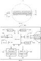
- FIG. 16 is a schematic structural diagram of an electronic device provided by an embodiment of the present disclosure.
- the present disclosure can also provide an electronic device 800, the electronic device 800 includes an RF circuit 810, a memory 820, an input unit 830, a display unit 840, a sensor 850, an audio circuit 860, a WiFi module 870, a processor 880, and a power supply 880 etc.
- the RF circuit 810, the memory 820, the input unit 830, the display unit 840, the sensor 850, the audio circuit 860 and the WiFi module 870 are respectively connected to the processor 880.
- the power supply 880 is used to provide electrical power to the entire electronic device 100.
- the RF circuit 810 is used to transmit and receive signals; the memory 820 is used to store data instruction information; the input unit 830 is used to input information, which may specifically include a touch panel 831 and other input devices 832 such as operation keys; the display unit 840 may include a display panel 841, etc.
- the sensor 850 include infrared sensor, laser sensor, etc. for detecting user proximity signals and distance signals, etc.
- the speaker 861 and the microphone (or microphones) 862 are connected to the processor 880 via the audio circuit 860 for receiving and transmitting sound signals.
- the WiFi module 870 is used to receive and transmit WiFi signals, and the processor 880 is used to process the data information of the electronic device.
Landscapes
- Engineering & Computer Science (AREA)
- Signal Processing (AREA)
- Ceramic Engineering (AREA)
- Textile Engineering (AREA)
- Chemical & Material Sciences (AREA)
- Mechanical Engineering (AREA)
- Devices For Indicating Variable Information By Combining Individual Elements (AREA)
Abstract
Description
- The present disclosure relates to the technical field of flexible display screens and, more particularly, to a support sheet, a flexible display screen and an electronic device.
- Electronic devices with flexible display screens, such as foldable mobile phones, can be bent, folded or even rolled. In order to facilitate the display area of the flexible display screen to realize changes and reduce the thickness of the flexible display screen as much as possible, the thickness of the flexible display screen, especially the support plate under the screen, needs to be very thin. However, if the thickness of the screen display support plate is too thin, the flexible circuit board in the flexible display screen is easily impacted by external forces during bending, which affects the reliability of the flexible display screen.
- Provided in the embodiments of the present disclosure is a support sheet for a flexible display screen. The support sheet includes a carbon fiber substrate. The carbon fiber substrate comprises first carbon fibers in a first direction and second carbon fibers in a second direction, the first direction being different from and angled with the second direction; and epoxy resin adhesive for holding the first and the second carbon fibers in the carbon fiber substrate.
- Provided in another aspect of the present disclosure is a flexible display screen, including a flexible display panel, a support sheet and a flexible circuit board. The support sheet is disposed on a non-display surface of the flexible display panel. One end of the flexible circuit board is electrically connected to the flexible display panel, and the opposite end of the flexible circuit board is attached to a side of the support sheet away from the flexible display panel. The support sheet includes a carbon fiber substrate, and the carbon fiber substrate includes first carbon fibers in a first direction and second carbon fibers in a second direction, the first direction being different from and angled with the second direction.
- Provided in a further aspect of the present disclosure is an electronic device, including a flexible display panel, a support sheet, a flexible circuit board and a main board. The support sheet disposed on the non-display surface of the flexible display panel. One end of the flexible circuit board is electrically connected to the flexible display panel, and the opposite end is attached to the side of the support sheet away from the flexible display panel. The flexible display panel is electrically connected to the main board through the flexible circuit board. The support sheet includes a carbon fiber substrate, and the carbon fiber substrate includes first carbon fibers in a first direction and second carbon fibers in a second direction; the first direction being different from and angled with the second direction.
- In order to illustrate the technical solutions in the embodiments of the present disclosure more clearly, the following briefly introduces the drawings that are used in the description of the embodiments.
-
FIG.1 is a schematic illustration of an electronic device according to some embodiments of the present disclosure. -
FIG.2 is a schematic cross-sectional view of the electronic device shown inFIG. 1 taken along the line A-A. -
FIG.3 is a schematic bottom view of a flexible display screen of an electronic device in the related art. -
FIG. 4 is a schematic cross-sectional view of the flexible display screen shown inFIG.3 taken along the line B-B. -
FIG.5 is an enlarged view of the area A shown inFig.4 . -
FIG.6 is a schematic bottom view of the flexible display screen in the electronic device as shown inFig.2 . -
FIG. 7 is a schematic cross-sectional view of the flexible display screen shown inFIG.6 , taken along the line C-C. -
FIG. 8 is an enlarged view of the area B shown inFig.7 . -
FIG.9 is a schematic cross-sectional view of an embodiment of a support sheet in the flexible display screen shown inFIG.6 , taken along the line D-D. -
FIG.10 is a schematic cross-sectional view of another embodiment of the support sheet in the flexible display screen shown inFIG.6 , taken along the line D-D. -
FIG.11 is a schematic cross-sectional view of another embodiment of the support sheet in the flexible display screen shown inFIG.6 , taken along the line D-D. -
FIG.12 is a schematic cross-sectional view of another embodiment of the support sheet in the flexible display screen shown inFIG.6 , taken along the line D-D. -
FIG. 13 is a schematic cross-sectional view of another embodiment of the support sheet in the flexible display screen shown inFIG.6 , taken along the line D-D. -
FIG.14 is a schematic cross-sectional view of a flexible display screen provided by another embodiment of the present disclosure. -
Fig.15 is a schematic enlarged view of the area C shown inFig. 13 . and -
FIG.16 is a schematic structural view of an electronic device provided by an embodiment of the present disclosure. - Embodiments of the present disclosure will be further described in detail below with reference to the accompanying drawings. It is particularly pointed out that the following examples are only used to illustrate the present disclosure, but do not limit the scope of the present disclosure. Similarly, the following embodiments are only some of the embodiments of the present disclosure, but not all of the embodiments, and all other embodiments obtained by those of ordinary skill in the art without creative work fall within the protection scope of the present disclosure.
- Please refer to
FIG. 1 , which is a schematic illustration of an electronic device according to some embodiments of the present disclosure. The present disclosure provides anelectronic device 1000. Theelectronic device 1000 may be any one of various types of computer system devices that are mobile or portable and capable of wireless communication (one form is exemplarily shown inFIG.1 ). Theelectronic device 1000 may be a mobile phone or smart phone, a portable gaming device (e.g. Nintendo DS TM, PlayStation Portable TM, Gameboy Advance TM, iPhone TM), laptop, PDAs, portable Internet devices, music players and data storage devices, other handheld devices or headphones. -
Electronic device 1000 may also be any of a number of electronic devices including, but not limited to, cellular phones, smart phones, other wireless communication devices, personal digital assistants, audio players, other media players, music recorders , video recorders, other media recorders, radios, medical equipment, vehicle transportation instruments, calculators, programmable remote controls, pagers, laptops, desktop computers, printers, netbooks, personal digital assistants (PDAs), portable multimedia players Video Players (PMP), Moving Picture Experts Group (MPEG-1 or MPEG-2) Audio Layer 3 (MP3) players, portable medical devices, and digital cameras and combinations thereof. - In some cases, the
electronic device 1000 may perform various functions e.g. play music, display video, store pictures, and receive and send phone calls.Electronic device 1000 may be a device such as a cellular phone, media player, other handheld device, wristwatch device, pendant device, handset device, or other compact portable device. - Please refer to
FIG.2 , which is a schematic cross-sectional view of theelectronic device 1000 shown inFIG.1 taken along the line A-A. Theelectronic device 1000 may include aflexible display screen 100 and ahousing 200. Theflexible display screen 100 is connected to thehousing 200 and is enclosed with thehousing 200 to form anaccommodating space 101 for accommodating batterie, amain board 400 and other component. - It should be noted that the terms "first", "second" and "third" in this disclosure are used for description purposes only, and should not be interpreted as indicating or implying relative importance or indicating the number of the indicated technical features. Thus, a feature defined as "first", "second", "third" may expressly or implicitly include at least one of that feature. In the description of the present disclosure, "a plurality of" means at least two, such as two, three, etc., unless otherwise expressly and specifically defined.
- Please refer to
FIGS.3 to 5, FIG. 3 is a schematic bottom view of a flexible display screen of an electronic device in the related art,FIG. 4 is a schematic cross-sectional view of the flexible display screen shown inFIG. 3 taken along the line B-B, andFIG. 5 is an enlarged view of the area A shown inFig. 4 . - In the related art, a
flexible display screen 600 may include aflexible display panel 601, an under-screen support plate 602, aflexible circuit board 603 and aheat sink 604. Theflexible display panel 601, the under-screen support plate 602 and theheat sink 604 are stacked in sequence. Theflexible circuit board 603 includes a first connectingportion 6031 and a second connectingportion 6032 that are arranged in parallel and spaced apart. The first connectingportion 6031 is attached to the surface of the under-screen support plate 602 away from theflexible display panel 601 for electrically connected to themain board 400 of theelectronic device 1000. Thesecond connection section 6032 is located between theflexible display panel 601 and the under-screen support plate 602, and thesecond connection section 6032 is electrically connected to theflexible display panel 601 for supplying power to theflexible display panel 601. - It can be understood that the under-
screen support plate 602 is located between theflexible display panels 601. On the one hand, it is used to support theflexible display panel 601, so that theflexible display panel 601 is evenly stressed, and on the other hand, it is used to protect theflexible circuit board 603 attached to the surface of the under-screen support board 602. Theflexible circuit board 603 is used to connect theflexible display panel 601 and themain board 400 of theelectronic device 1000, so that themain board 400 can transmit signals to theflexible display panel 601 or receive signals fed back by theflexible display panel 601. Theheat sink 604 is used to conduct the heat absorbed by the under-screen support plate 602, so as to improve the heat dissipation performance of theflexible display screen 600. - Understandably, the thickness of the under-
screen support plate 602 needs to be made very thin in order to make theflexible display screen 600 or even theelectronic device 1000 thin enough and to facilitate the under-screen support plate 602 to be able to change state with theflexible display panel 601 such as bendable. However, due to the dense arrangement of circuits in theflexible circuit board 603, when theflexible circuit board 603 is subjected to excessive pressure, it is very likely to fail. Therefore, it is necessary to increase the thickness of the under-screen support plate 602 to ensure its strength. It is necessary to make a trade-off between the thickness of thelower support plate 602 and the thickness of theflexible display screen 600. In a related art, the under-screen support plate 602 is usually made of stainless steel or titanium sheets. In order to meet the strength requirements for protecting theflexible circuit board 603, the thickness of the under-screen support plate 602 is usually more than 0.15 mm, that is, the under-screen support plate 602 is added in thickness to ensure the reliability of theflexible display screen 600. However, the thickness of the under-screen support plate 602 is too thick, which not only increases the thickness of theflexible display screen 600, but also greatly increases the weight of theflexible display screen 600. In addition, the excessively thick under-screen support plate 602 also affects its own bendable strength makes it more difficult to bend and deform. In view of this, it is necessary to provide a new flexible display screen. - Reference herein to an "embodiment" means that a particular feature, structure, or characteristic described in conjunction with the embodiment can be included in at least one embodiment of the present disclosure. The appearance of the phrase in various places in the specification is not necessarily all referring to the same embodiment, nor is it a separate or alternative embodiment that is mutually exclusive with other embodiments. It is explicitly and implicitly understood by those skilled in the art that the embodiments described herein may be combined with other embodiments.
- Please refer to
FIGS. 6 to 8 ,FIG. 6 is a schematic bottom view of the flexible display screen in the electronic device shown inFIG. 2 ,FIG. 7 is a schematic cross-sectional view of the flexible display screen shown inFIG. 6 taken along the line C-C, andFIG . 8 is an enlarged view of the area B shown inFig. 7 . - The embodiment of the present disclosure provides the
flexible display screen 100, which may include aflexible display panel 10, an under-screen support plate 20, asupport sheet 30, aflexible circuit board 40 and a heat sink 50. Theflexible display panel 10 is disposed on a first face of the under-screen support plate 20, and thesupport sheet 30 and the heat sink 50 are disposed on a second face of the under-screen support plate 20, the first face is opposite to the second face. Theflexible circuit board 40 includes a first connectingportion 41 and a second connectingportion 42 arranged in substantial parallel and spaced apart from each other. The first connectingportion 41 is attached to a surface of thesupport sheet 30 away from the under-screen support plate 20 for electrically connected to themain board 400 of theelectronic device 1000. Thesecond connection portion 42 is located between theflexible display panel 10 and the under-screen support plate 20, and thesecond connection portion 42 is electrically connected to theflexible display panel 10. - The
support sheet 30 is attached to the second face of the under-screen support plate 20 away from theflexible display panel 10, and is used to enhance the strength of the under-screen support plate 20 at the corresponding position of thesupport sheet 30. Thesupport sheet 30 is disposed corresponding to thesecond connection portion 42 to sufficiently protect thesecond connection portion 42 of theflexible circuit board 40 to reduce the possibility of theflexible circuit board 40 being damaged. - It can be understood that the
support sheet 30 and the heat sink 50 are respectively coupled to the second face of the under-screen support plate 20 away from theflexible display screen 100. Compared with the related art, only thesupport sheet 30 is added, without increasing the thickness of the under-screen support plate 40, which not only improves the strength of the under-screen support plate 20 corresponding to the position of thesecond connection part 42, but also does not increase the overall thickness of theflexible display screen 100, and reduces the weight of theflexible display screen 100. That is, without increasing the thickness of theflexible display screen 100, the strength of the under-screen support plate 20 is greatly improved, and the reliability of theflexible circuit board 40 is improved. - The
flexible display panel 10 may include acircuit connection area 11, and thecircuit connection area 11 is disposed on the side of theflexible display panel 10 facing the first face of the under-screen support plate 20 and at the edge of theflexible display panel 10. Thecircuit connection area 11 is electrically connected to thefirst connection portion 41 of theflexible circuit board 40, and is used to realize the transmission of electrical signals between theflexible display panel 10 and themain board 400 of theelectronic device 100. - In this embodiment, since the
support sheet 30 can improve the structural strength of the under-screen support plate 20 at the corresponding position, the thickness of the under-screen support plate 20 can be appropriately reduced. Specifically, the thickness of the under-screen support plate 20 may be 0.10-012 mm. Compared with the related art, the thickness of the under-screen support plate 20 is approximately reduced by 0.03-0.05 mm, and correspondingly, the weight of the under-screen support plate 20 is reduced by 20-33%. In addition, since the thickness of the under-screen support plate 20 is reduced, the under-screen support plate 20 is more likely to be bent, thereby making the bendable of theflexible display screen 100 more labor-saving. In this embodiment, the material of the under-screen support plate 20 may be stainless steel or titanium alloy, which is not specifically limited herein. - In some embodiments, the under-
screen support plate 20 may include abendable area 21 and anon-bendable area 22 respectively located on both sides of thebendable area 21 and corresponding to thebendable area 21. Thebendable area 21 can be bent along the folding line L, so as to drive thenon-bendable areas 22 to approach each other, so as to realize the bendable of theflexible display screen 100. Thebendable area 21 is provided with a plurality of through-holes 211, or thebendable area 21 may have a grid structure, so as to enhance the bendability of thebendable area 21. Thesupport piece 30 is disposed in thenon-bendable area 22 of the under-screen support plate 20. - Please refer to
FIGS. 9 to 12 ,FIG. 9 is a schematic cross-sectional view of an embodiment of the support sheet in the flexible display screen shown inFIG. 6 taken along the line D-D, andFIG. 10 is a schematic cross-sectional view of another embodiment of the support sheet in the flexible display screen shown inFIG. 6 taken along the line D-D.FIG. 11 is a schematic cross-sectional view of another embodiment of the support sheet in the flexible display screen shown inFIG.6 taken along the line D-D.FIG.12 is a schematic cross-sectional view of another embodiment of the support sheet in the flexible display screen shown inFIG.6 , taken along the line D-D. - The
support sheet 30 may include, but is not limited to, acarbon fiber substrate 31 and an epoxy resin adhesive 32 coated on thecarbon fiber substrate 31. Thecarbon fiber substrate 31, also known as carbon fiber cloth, carbon fiber woven cloth, carbon fiber prepreg cloth, carbon fiber reinforcement cloth, carbon cloth, carbon fiber fabric, carbon fiber tape, or carbon fiber sheet, is made of carbon fibers. The carbon fiber has the advantage of high strength, low density, thin thickness, etc. Carbon fiber is mainly composed of carbon elements, and has the characteristics of high temperature resistance, friction resistance, electrical conductivity, thermal conductivity and corrosion resistance. Carbon fiber is fibrous, soft, and can be processed into various fabrics. The carbon fiber has high tensile strength and tensile modulus along it's fiber axis direction. Carbon fiber has the advantages of low density, high specific strength and specific modulus. The main material of theepoxy resin adhesive 32 is epoxy resin. The epoxy resin has excellent physical and mechanical properties, electrical insulation properties, and adhesion properties with various materials, especially adhesion properties with metals. - It can be understood that the
carbon fiber substrate 31 can be formed by carbon fibers in different directions. In some embodiments, thecarbon fiber substrate 31 can be woven from carbon fiber warp and weft threads. In some embodiments, the warp and weft threads of thecarbon fiber substrate 31 form a grid structure. Theepoxy resin adhesive 32 is located in thecarbon fiber substrate 31 and on the surface of thecarbon fiber substrate 31, for bonding thecarbon fiber substrate 31 and making thecarbon fiber substrate 31 sticky during the formation of thesupport sheet 30. In some embodiments, theepoxy resin adhesive 32 is located in the grid structure. The direction of the warp threads defines a first direction of thecarbon fiber substrate 31, and the direction of the weft threads defines a second direction of thecarbon fiber substrate 31; the first direction is different form and angled with the second direction. In some embodiments, the first direction and the second direction are substantially perpendicular to each other. The carbon fibers in the first direction may be the first carbon fibers, and the carbon fibers in the second direction may be the second carbon fibers. Thecarbon fiber substrate 31 includes the first carbon fibers in the first direction and the second carbon fibers in the second direction. Thecarbon fiber substrate 31 has carbon fibers in different directions, which can make thecarbon fiber substrate 31 have high compressive strength and compressive modulus in different directions. Epoxy resin adhesive 32 in thecarbon fiber substrate 31 is used to improve the tensile modulus, flexural modulus and flexural strength of thesupport sheet 30. The epoxy resin adhesive 32 can be used to make thecarbon fiber substrate 31 attached to the under-screen support plate 20, to prevent thecarbon fiber substrate 31 from detaching from the screendisplay support sheet 30 and affect the reliability of thesupport sheet 30. - The
support sheet 30 of the flexible display screen provided by the embodiment of the present disclosure can be formed of a carbon fiber substrate and an epoxy resin adhesive. Due to the preferential orientation of the carbon fiber along the fiber axis, it has high tensile strength and tensile modulus along the fiber axis direction, the carbon fiber substrate is formed of carbon fibers in the first direction and the second direction, and has high tensile strength and tensile modulus in different directions, so the carbonfiber support sheet 30 can have good bendable performance. When applied to foldable flexible displays, the carbon fiber support is well suited to the folding and unfolding requirements of flexible displays without being easily damaged, and have a significant weight advantage over the stainless steel support and titanium support sheet. - In some embodiments, the epoxy resin adhesive 32 can be coated on the surface of the
carbon fiber substrate 31 through a coating process and penetrated into the grid structure of thecarbon fiber substrate 31, so that the bonding of the epoxy resin adhesive 32 with thecarbon fiber substrate 31 can be achieved both for the internal structure of thecarbon fiber substrate 31 and for making the surface of thecarbon fiber substrate 31 sticky. It can be understood that the epoxy resin adhesive 32 can also penetrate into the grid structure of thecarbon fiber substrate 31 through the deposition process and be fully combined with thecarbon fiber substrate 31, which can not only realize the bonding of the internal structure of thecarbon fiber substrate 31, but also realize the surface of the carbon fiber substrate31sticky. In addition, theepoxy resin adhesive 32 and thecarbon fiber substrate 31 can also be bonded by an injection molding process. Specifically, carbon fibers can be cut into short fibers and put into a specified mold, and then epoxy resin can be injected into a specified mold. The adhesive 32 can fully combine thecarbon fiber substrate 31 and the epoxy resin adhesive 32 through extrusion injection. - The
support sheet 30 is located between the first connectingportion 41 and the under-screen support plate 20 and is respectively bonded and fixed to the first connectingportion 41 and the under-screen support plate 20. In some embodiments, thesupport sheet 30 is bonded with the first connectingportion 41 and the under-screen support plate 20 by double-sided pressure-sensitive adhesive. In some embodiments, thesupport sheet 30 is bonded to the under-screen support plate 20 using 3M 9750 pressure sensitive adhesive. Thesupport sheet 30 is bonded to thefirst connection part 41 using Tesa 61350 adhesive. - Optionally, the thickness of the
support sheet 30 is approximately between 0.10-0.15mm, such as 0.10mm, 0.12mm or 0.15mm, which is not limited herein. Specifically, the thickness of the heat sink 50 is approximately between 0.20-0.30 mm. When the second connectingportion 42 of theflexible circuit board 40 and the supportingsheet 30 are stacked and arranged, the thickness of the supportingsheet 30 and the second connectingportion 42 is the same as the thickness of the heat sink 50, which can not only make the force of the under-screen support plate 20 uniform, but also do not increase the thickness of theflexible display screen 100 , and make full use of the existing space of theflexible display screen 100 . - In some embodiments, the
support sheet 30 may include at least three layers ofcarbon fiber substrate 31, that is, thecarbon fiber substrate 30 includes at least three carbon fiber substrate layers, and may be four carbon fiber substrate layers, five carbon fiber substrate layers, or the like. Specifically, since the thickness of the single-layercarbon fiber substrate 31 is between 0.025-0.05 mm, if thesupport sheet 30 has only one or two layers of thecarbon fiber substrate 31, thesupport sheet 30 is easily bent and deformed and has no support. In addition, if the thickness of the single carbon fiber substrate layer is greater than 0.05 mm, thesupport sheet 30 may also include two carbon fiber substrate layers. In some embodiments, thecarbon fiber substrates 31 may include three layers of first carbon fiber substrate layers 311 (as shown inFIG. 9 ) which includes the first carbon fibers in the first direction. In some embodiments, thecarbon fiber substrates 31 may include three layers of second carbon fiber substrate layers 312 (as shown inFIG. 10 ) which includes the second carbon fibers in the second direction. The first carbonfiber substrate layer 311 is M40 carbon fiber, and the thickness of the single first carbonfiber substrate layer 311 is 0.05 mm; the second carbonfiber substrate layer 312 is T700 carbon fiber, and the thickness of the single-layer second carbonfiber substrate layer 312 is 0.025 mm. The M40 carbon fiber in this embodiment refers to the M40 grade carbon fiber, and the T700 carbon fiber refers to the T700 grade carbon fiber. For details, please refer to the specific parameters in Table 1 below. - In some embodiments, the
carbon fiber substrates 31 may include a first carbonfiber substrate layer 311 and a second carbonfiber substrate layer 312 that are stacked together. In some embodiments, thecarbon fiber substrates 31 may include at least one first carbonfiber substrate layer 311 and at least two layers of second carbon fiber substrate layers 312 stacked together, wherein any one of the first carbonfiber substrate layer 311 is located between two adjacent layers of the second carbon fiber substrate layers 312 (as shown inFIG 11 ). Specifically, the first carbonfiber substrate layer 311 may be formed by the first carbon fibers in a first direction, and the second carbonfiber substrate layer 312 may be formed by the second carbon fibers in a second direction; the first direction is different form and angled with the second direction. In some embodiments, the first direction and the second direction are substantially perpendicular to each other.Table 1: Performance parameters of the first carbon fiber substrate layer and the second carbon fiber substrate layer Category First carbon fiber substrate layer Second carbon fiber substrate layer Tensile modulus/G pa 392 230 Tensile strength/M pa 2740 4900 Thickness/mm 0.05 0.025 Density g/cm 3 1.80 1.81 - It can be seen from Table 1 that in terms of tensile modulus (elastic deformation and plastic deformation), the first carbon
fiber substrate layer 311 > the second carbonfiber substrate layer 312; in terms of tensile strength (hardness), the firstcarbon fiber substrate 311 layer < the second carbonfiber substrate layer 312; in terms of thickness, the first carbonfiber substrate layer 311>the second carbonfiber substrate layer 312; in terms of density, the first carbonfiber substrate layer 311 and the second carbonfiber substrate layer 312 have little difference. - In some embodiments, the
carbon fiber substrates 31 may include a first carbonfiber substrate layer 311 and a second carbonfiber substrate layer 312 and a third substrate 313(as shown inFIG. 12 ). Thethird substrate 313 may be formed by the first carbon fibers in a first direction or formed by the second fibers in a second direction. Optionally, thethird substrate 313 may be formed by third fibers in a third direction; the third direction is different form and angled with the first and second directions. In some embodiments, the first carbonfiber substrate layer 311 is located between the second carbonfiber substrate layer 312 and a third carbonfiber substrate layer 313, and a thickness of the first carbonfiber substrate layer 311 is greater than the thickness of the second carbonfiber substrate layer 312 and the third carbonfiber substrate layer 313. - In some embodiments, the mass fraction of the epoxy resin adhesive 32 in the
support sheet 30 is approximately between 30% and 40%. Specifically, since thecarbon fiber substrate 31 has a grad structure and does not have adhesive properties, it is necessary to coat theepoxy resin adhesive 32 on thecarbon fiber substrate 31 to increase the viscosity of thecarbon fiber substrate 31. - The
support sheet 30 can be a first support sheet, a second support sheet and a third support sheet, wherein the first support sheet includes three layers of the first carbonfiber substrate layer 311 and the epoxy resin adhesive 32 with a mass fraction of 40%, and the second support sheet includes three the second carbon fiber substrate layers 312 and the epoxy resin adhesive 32 with a mass fraction of 40%, and the third support sheet includes a layer of the first carbonfiber substrate layer 311, two layers of the second carbonfiber substrate layer 312 and the epoxy resin adhesive 32 with a mass fraction of 40%.Table 2: Performance parameters of the first support sheet, the second support sheet and the third support sheet Category First support sheet Second support sheet Third support sheet Tensile modulus/Gpa 240 135 180 Tensile strength/Mpa 1470 2550 1860 Thickness/mm 0.15 0.075 0.010 Density g/cm3 1.61 1.60 1.60 - It can be seen from Table 2: in terms of tensile modulus (elastic deformation and plastic deformation), the first support sheet > the third support sheet > the second support sheet, that is, the first support sheet has the highest tensile modulus of the three support sheets. In terms of tensile strength (hardness), the first support sheet < the third support sheet < the second support sheet, that is, the second support sheet has the highest tensile strength of the three support sheets. In terms of thickness, the first supporting sheet > the third supporting sheet support sheet>second support sheet, that is, the second support sheet has the smallest thickness of the three support sheets. In terms of density, there is little difference among the three sheets. Considering comprehensively, the third support sheet has great advantages in tensile modulus, tensile strength and thickness.
- Please comprehensively compare Table 1 and Table 2. It can be clearly seen from Table 1 and Table 2 that whether it is the first carbon
fiber substrate layer 311 or the second carbonfiber substrate layer 312, when theepoxy resin adhesive 32 is coated on the surface of the carbon fiber, the tensile modulus and tensile strength of the carbon fiber are obviously decreased, so the mass fraction of the epoxy resin adhesive 32 in thesupport sheet 30 needs to be properly controlled. - If the mass fraction of the
epoxy resin adhesive 32 is too large, for example, the mass fraction of theepoxy resin adhesive 32 exceeds 40%, the overall tensile modulus, flexural modulus and flexural strength of thesupport sheet 30 will be affected. If the mass fraction of theresin adhesive 32 is too small, for example, the mass fraction of theepoxy resin adhesive 32 is less than 30%, the viscosity of thesupport sheet 30 is insufficient, which affects the reliability of thesupport sheet 30. Therefore, the mass fraction of the epoxy resin adhesive 32 in thesupport sheet 30 is preferably between 30% and 40%, for example, the mass fraction of the epoxy resin adhesive 32 in thesupport sheet 30 may be 30%, 32%, 33%, 34%, 35%, 37%, 39% or 40%, Not to be listed all here. - Further, the mass fraction of the epoxy resin adhesive 32 in the
support sheet 30 is between 32% and 34%, and preferably, the mass fraction of the epoxy resin adhesive 32 in thesupport sheet 30 is 33%. Through the above manner, the tensile modulus, flexural modulus and bending strength of thesupport sheet 30 can meet the design requirements, and thesupport sheet 30 can be adhesively connected with the under-screen support plate 20 to ensure the reliability of thesupport sheet 30. - Optionally, the material of the support sheet may be stainless steel, titanium alloy or the like. In order to ensure the strength of the support sheet, the thickness of the
support sheet 30 is between 0.10-0.15 mm. Specifically, please refer to Table 3:Table 3: Performance parameter table of carbon fiber support sheet, stainless steel support sheet and titanium alloy support sheet Category Carbon fiber support sheet Stainless steel support sheet Titanium alloy support sheet Tensile modulus/Gpa 135-240 190-210 110-120 Flexural modulus/Gpa 130-180 130-150 110-110 Tensile strength/Mpa 1470-2550 600-1500 400-1000 Density g/cm 3 1.80 7.9 4.5 Price Low Low high Magnetic Non-magnetic Low magnetism after heat treatment Non-magnetic - Please refer to Table 2 and Table 3 at the same time, the tensile modulus of the first support sheet in the carbon fiber support sheet is 240Gpa, and the tensile modulus of the third support sheet is 180Gpa, which is similar to the tensile modulus of the stainless steel support sheet of 190-210Gpa , and is much larger than the tensile modulus of the titanium alloy support sheet of 110-120Gpa; the lower limit of the tensile strength of the first support sheet, the second support sheet and the
third support sheet 30 in the carbon fiber support sheet is 1470Mpa, which is similar to the upper limit of the tensile strength of the stainless steel supports of 1500Mpa and much greater than the tensile strength of the titanium alloy supports of 1000Mpa. It can be concluded that the tensile modulus and tensile strength of the carbon fiber support sheet are not weaker than or even better than that of the titanium alloy support sheet. - Further, it can be seen from Table 3 that the density of the carbon fiber support sheet is significantly lower than that of the stainless steel support sheet and the titanium alloy support sheet. Taking the stainless steel support sheet and the carbon fiber support sheet with a volume of 138.78mm 3 as an example, the weight of the stainless steel support sheet is 1.08g, while the weight of the carbon fiber is 0.22g, which is 0.86g less than the weight of the stainless steel support sheet. That is, the weight of the carbon fiber support sheet is 79% lower than that of the stainless steel support sheet of the same volume. Similarly, the carbon fiber support sheet is 60% lighter than the titanium alloy support sheet of the same volume.
- Furthermore, since the carbon fiber support sheet has no magnetism, it does not need to be demagnetized, which can reduce the processing process. The stainless steel support piece has magnetism, so in order to reduce the influence of the stainless steel magnetism on the precision of the components in the electronic device 100 (for example, the magnet in the camera), the stainless steel support piece needs to be degaussed. But even if the stainless steel support piece is demagnetized, it still has weak magnetic properties. The price of titanium alloy is relatively expensive, and the cost of mass application is high, which is not suitable for large-scale production.
- Please refer to
FIG. 13. FIG. 13 is a schematic cross-sectional view of another embodiment of the support sheet in the flexible display screen shown inFIG.6 taken along the line D-D. - Optionally, the
support sheet 30 may further include aconductive layer 33, and theconductive layer 33 is disposed on the surface of theepoxy resin adhesive 32. Theconductive layer 33 is used to ground the static electricity on the under-screen support plate 20 and thesupport sheet 30 to prevent static electricity from damaging the circuit of theflexible display panel 10 or theflexible circuit board 40. - The
conductive layer 33 is deposited on the surface of theepoxy resin adhesive 32 by physical vapor deposition or water plating, so that theconductive layer 33 is uniformly coated on the surface of theepoxy resin adhesive 32. - Specifically, the manufacturing process of the
support sheet 30 may include the following operations: - S01, stacking and arranging at least three layers of
carbon fiber substrates 31, and coating uniformly theepoxy resin adhesive 32 on the surface of thecarbon fiber substrates 31. - S02, hot-pressing the
carbon fiber substrate 31 coated with the epoxy resin adhesive 32 to obtain a semi-finished product; - S03, cutting and trimming the semi-finished product to obtain the
support sheet 30. - Please refer to
FIG 8 , in thesupport sheet 30 provided in the embodiment of the present disclosure, by coating theepoxy resin adhesive 32 on thecarbon fiber substrate 31, on the one hand, the support sheet 30has the advantages of high tensile modulus and high tensile strength, and on the other hand, thesupport sheet 30 has the advantages of high tensile modulus and high tensile strength; in addition, the thickness of thesupport sheet 30 is 0.10-0.15 mm, so that the thickness of thesupport sheet 30 is relatively thin. - The
flexible circuit board 40 may be approximately in a "U" shape, and theflexible circuit board 40 may further include a third connectingportion 43 connecting the first connectingportion 41 and the second connectingportion 42, and the third connectingportion 43 abuts against the under-screen support plate 20 and the edge of thesupport sheet 30 for making theflexible circuit board 40 fully fit with thesupport sheet 30 to improve space utilization. - The heat sink 50 may include a
first heat sink 51 and asecond heat sink 52, thefirst heat sink 51 and thesecond heat sink 52 are respectively disposed on the twonon-bendable regions 22, wherein thefirst heat sink 51 is provided adjacent to thesupport piece 30. Specifically, the heat sink 50 may be a material with good thermal conductivity, e.g. graphite or copper sheet. - In the
flexible display screen 100 provided by the embodiment of the present disclosure, asupport sheet 30 is provided between the under-screen support plate 20 and thefirst connection portion 41 of theflexible display screen 100 to increase the structural strength of thefirst connection section 41 at the position corresponding to thesupport piece 30. At the same time, due to the existence of thesupport sheet 30, the thickness of the under-screen support plate 20 can be appropriately reduced, thereby the thickness and weight of theflexible display screen 100 can be reduced. - Please refer to
FIG. 14 andFIG. 15 ,FIG. 14 is a schematic cross-sectional view of a flexible display screen taken along the line C-C provided by another embodiment of the present disclosure, andFIG. 15 is an enlarged view of the area C shown inFIG. 14 . - The embodiment of the present disclosure further provides a
flexible display screen 300, and theflexible display screen 300 may include aflexible display panel 301, asupport sheet 30, aflexible circuit board 302 and aheat sink 303. Theflexible display panel 301, thesupport sheet 30 and theheat sink 303 are stacked in sequence, wherein the shape of thesupport sheet 30 corresponds to the shape of theflexible display panel 301, so that thesupport sheet 30 can fully contact theflexible display panel 301 and support and protect theflexible display panel 301. Thesupport sheet 30 is a carbonfiber support sheet 30. - The
support sheet 30 of the flexible display screen provided by the embodiments of the present application may be formed of a carbon fiber substrate 31and anepoxy resin adhesive 32. Specifically, thecarbon fiber substrate 31 may be formed of carbon fibers in different directions. The carbon fiber substrate includes the first carbon fibers in the first direction and the second carbon fibers in the second direction. The carbon fiber substrate thus formed has carbon fibers in different directions, which can make the carbon fiber substrate have high tensile strength and resistance in different directions. In some embodiments, thecarbon fiber substrate 31 may be at least three carbon fiber substrate layers, and the at least three carbon fiber substrate layers may include a first carbonfiber substrate layer 311 and a second carbonfiber substrate layer 312 that are stacked in sequence. Specifically, the first carbonfiber substrate layer 311 may be formed by first carbon fibers in a first direction, and the second carbonfiber substrate layer 312 may formed by second carbon fibers in a second direction, the first direction is different form and angled with the second direction. In some embodiments, the first direction and the second direction are substantially perpendicular to each other. The flexible displayscreen support sheet 30 provided in the embodiment of the present application contacts and supports the flexible display panel, and when applied to foldable electronics, it can well satisfy the folding and unfolding of the flexible display screen without being easily damaged. It has great advantages in weight for stainless steel support pieces and titanium alloy support pieces. - The
support sheet 30 may include abendable area 34 and anon-bendable area 35 respectively located on both sides of thebendable area 34 and corresponding to thebendable area 34. Thebendable area 34 can be bent along the folding line L, so as to drive thenon-bendable areas 35 to approach each other, so as to realize the bendable of the flexible display screen 300.Thebendable area 34 may have a grid structure, or a plurality of through holes (not shown) to enhance the bendability of thebendable area 34. The number ofheat sink 303 is two and corresponds to the twonon-bendable regions 35 respectively. - The
flexible circuit board 302 may be approximately in a "U" shape and include a first connectingpart 3021 and a second connectingpart 3022 arranged in parallel and spaced apart, and a third connecting part 3023 connecting the first connectingpart 3021 and the second connectingpart 3022. The first connectingpart 3021 is attached to the surface of thesupport sheet 30 away from theflexible display panel 301, and is used to electrically connect thefirst connection part 3021 with themain board 400 of theelectronic device 100; thesecond connection part 3022 is located between theflexible display panel 301 and thesupport sheet 30, and thesecond connection portion 3022 is electrically connected to theflexible display panel 301. - The heat sink may include a
first heat sink 303 and asecond heat sink 303. Thefirst heat sink 303 and thesecond heat sink 303 are respectively disposed on the twonon-bendable areas 35, wherein thefirst heat sink 303 is provided adjacent to thesupport sheet 30. Specifically, theheat sink 303 may be a material with good thermal conductivity, e.g. graphite or copper sheet. - Please refer to
FIG. 16 , which is a schematic structural diagram of an electronic device provided by an embodiment of the present disclosure. - Of course, the present disclosure can also provide an
electronic device 800, theelectronic device 800 includes anRF circuit 810, amemory 820, aninput unit 830, adisplay unit 840, asensor 850, anaudio circuit 860, aWiFi module 870, aprocessor 880, and apower supply 880 etc. TheRF circuit 810, thememory 820, theinput unit 830, thedisplay unit 840, thesensor 850, theaudio circuit 860 and theWiFi module 870 are respectively connected to theprocessor 880. Thepower supply 880 is used to provide electrical power to the entireelectronic device 100. - Specifically, the
RF circuit 810 is used to transmit and receive signals; thememory 820 is used to store data instruction information; theinput unit 830 is used to input information, which may specifically include atouch panel 831 andother input devices 832 such as operation keys; thedisplay unit 840 may include adisplay panel 841, etc. Thesensor 850 include infrared sensor, laser sensor, etc. for detecting user proximity signals and distance signals, etc. Thespeaker 861 and the microphone (or microphones) 862 are connected to theprocessor 880 via theaudio circuit 860 for receiving and transmitting sound signals. TheWiFi module 870 is used to receive and transmit WiFi signals, and theprocessor 880 is used to process the data information of the electronic device. - The above descriptions are only part of the embodiments of the present disclosure, and are not intended to limit the protection scope of the present disclosure. Any equivalent device or equivalent process transformation made by using the contents of the description and drawings of the present disclosure, or directly or indirectly applied to other related technical field is similarly included in the scope of patent protection of this disclosure.
Claims (15)
- A support sheet (30) for a flexible display screen (100,300), comprising:a carbon fiber substrate (31), the carbon fiber substrate (31) comprising first carbon fibers in a first direction and second carbon fibers in a second direction; wherein the first direction being different from and angled with the second direction; andepoxy resin adhesive (32) for holding the first and the second carbon fibers in the carbon fiber substrate (31).
- The support sheet (30) according to claim 1, wherein the first direction being perpendicular to the second direction.
- The support sheet (30) according to claim 1 or 2, wherein the carbon fiber substrate (31) comprises at least two carbon fiber substrate layers, and the at least two carbon fiber substrate layers comprise a first carbon fiber substrate layer (311) and a second carbon fiber substrate layer (312) that are stacked in sequence, wherein, the first carbon fiber substrate layer (311) is formed by the first carbon fibers, and the second carbon fiber substrate layer (312) is formed by the second carbon fibers.
- The support sheet (30) according to claim 1 or 2, wherein the carbon fiber substrate (31) comprises at least three carbon fiber substrate layers, and the at least three carbon fiber substrate layers comprise a first carbon fiber substrate layer (311) and a second carbon fiber substrate layer (312) that are stacked in sequence, wherein the first carbon fiber substrate layer (311) is formed by the first carbon fibers, and the second carbon fiber substrate layer (312) is formed by the second carbon fibers.
- The support sheet (30) according to any of claims 1-4, wherein a tensile modulus of the first carbon fiber substrate layer (311) is greater than the tensile modulus of the second carbon fiber substrate layer (312), and a tensile strength of the first carbon fiber substrate layer (311) is less than the tensile strength of the second carbon fiber substrate layer (312).
- The support sheet (30) according to any of claims 1-4, wherein, the first carbon fiber substrate layer (311) and the second carbon fiber substrate layer (312) have a same tensile modulus and a same tensile strength.
- The support sheet (30) according to claim 4, wherein the first carbon fiber substrate layer (311) is located between the second carbon fiber substrate layer (312) and a third carbon fiber substrate layer (313), and a thickness of the first carbon fiber substrate layer (311) is greater than the thickness of the second carbon fiber substrate layer (312) and the third carbon fiber substrate layer (313).
- The support sheet (30) according to any of claims 1-7, wherein the support sheet (30) has a bendable area (34) and a non-bendable area (35), wherein the bendable area (34) has multiple through-holes (211).
- The support sheet (30) according to any of claims 1-7, wherein the mass fraction of the epoxy resin adhesive (32) in the carbon fiber substrate (31) is 30% - 40%.
- The support sheet (30) according to any of claims 1-7, wherein the support sheet (30) further comprises a conductive layer (33), and the conductive layer (33) is disposed on a surface of the carbon fiber substrate (31).
- A flexible display screen (100,300), comprising:a flexible display panel (10,301);a support sheet (30) according to any of claims 1 to 10, the support sheet (30) comprising a first face and a second face opposite to the first face, the first face being coupled to a non-display surface of the flexible display panel (10,301); anda flexible circuit board (40,302), comprising a first portion (41,3021) and a second portion (42,3022), the first portion (41,3021) being electrically connected to the flexible display panel (10,301), the second portion (42,3022) being attached to the second face of the support sheet (30);
- The flexible display screen (100,300) according to claim 11, wherein the flexible display screen (100) has a heat sink (50,303), and the heat sink (50,303) is disposed in the non-bendable area (35) on the side of the support sheet (30) facing away from the flexible display panel (10, 301).
- An electronic device (1000), comprising:a flexible display panel (10,301);a support sheet (30) according to any of claims 1 to 10, the support sheet (30) being coupled to a non-display surface of the flexible display panel (10,301);a main board (400);a flexible circuit board (40,302), one portion of the flexible circuit board (40,302) being electrically connected to the flexible display panel (10,301), and another portion of the flexible circuit board (40,302) being attached to a side of the support sheet (30) away from the flexible display panel (10,301), wherein the flexible display panel (10,301) is electrically connected to the main board (400) through the flexible circuit board (40,302).
- The electronic device (1000) according to claim 13, wherein the flexible circuit board (40,302), comprising a first portion (41,3021) and a second portion (42,3022), the first portion (41,3021) being electrically connected to the flexible display panel (10,301), the second portion (42,3022) being attached to the second face of the support sheet (30);
- The electronic device (1000) according to claim 13, wherein electronic device (1000) has a heat sink (50,303), and the heat sink (50,303) is disposed in the non-bendable area (35) on the side of the support sheet (30) facing away from the display panel (10,301).
Applications Claiming Priority (1)
| Application Number | Priority Date | Filing Date | Title |
|---|---|---|---|
| CN202110738285.9A CN113472926A (en) | 2021-06-30 | 2021-06-30 | Support sheet, flexible display screen and electronic equipment |
Publications (1)
| Publication Number | Publication Date |
|---|---|
| EP4112292A1 true EP4112292A1 (en) | 2023-01-04 |
Family
ID=77876706
Family Applications (1)
| Application Number | Title | Priority Date | Filing Date |
|---|---|---|---|
| EP22181412.2A Withdrawn EP4112292A1 (en) | 2021-06-30 | 2022-06-28 | Support sheet, flexible display screen and electronic device |
Country Status (4)
| Country | Link |
|---|---|
| US (1) | US20230010332A1 (en) |
| EP (1) | EP4112292A1 (en) |
| CN (2) | CN115174715A (en) |
| WO (1) | WO2023273961A1 (en) |
Families Citing this family (19)
| Publication number | Priority date | Publication date | Assignee | Title |
|---|---|---|---|---|
| CN115174715A (en) * | 2021-06-30 | 2022-10-11 | Oppo广东移动通信有限公司 | Flexible display screen supporting sheet, flexible display screen and electronic equipment |
| KR20230023879A (en) * | 2021-08-10 | 2023-02-20 | 삼성디스플레이 주식회사 | Display device |
| CN115019636B (en) * | 2021-10-26 | 2023-08-15 | 荣耀终端有限公司 | Flexible display module and electronic equipment |
| CN217238773U (en) * | 2022-01-24 | 2022-08-19 | 华为技术有限公司 | Supporting layer group applied to electronic equipment, display module and electronic equipment |
| CN114523735B (en) * | 2022-02-21 | 2024-03-01 | 京东方科技集团股份有限公司 | Support component, manufacturing method and display device |
| CN116696926A (en) * | 2022-02-28 | 2023-09-05 | Oppo广东移动通信有限公司 | Support plate, flexible display screen and electronic equipment |
| CN116741040B (en) * | 2022-03-02 | 2025-12-16 | Oppo广东移动通信有限公司 | Supporting structure and electronic equipment |
| CN116935743A (en) * | 2022-03-31 | 2023-10-24 | Oppo广东移动通信有限公司 | Supports, flexible screen components and foldable electronic devices |
| CN114822268A (en) * | 2022-05-31 | 2022-07-29 | Oppo广东移动通信有限公司 | Support plate, display assembly and flexible screen electronic equipment |
| KR20240007970A (en) * | 2022-07-07 | 2024-01-18 | 삼성디스플레이 주식회사 | Electronic device |
| KR20240055968A (en) * | 2022-10-20 | 2024-04-30 | 삼성디스플레이 주식회사 | Display device |
| CN116016730A (en) * | 2022-12-13 | 2023-04-25 | 维沃移动通信有限公司 | Electronic equipment |
| CN117153042B (en) * | 2023-01-13 | 2024-10-29 | 荣耀终端有限公司 | Folding screen device and method for manufacturing fiber composite board |
| CN116504140A (en) * | 2023-04-28 | 2023-07-28 | 维沃移动通信有限公司 | Support frame, screen assembly, electronic device and method of manufacturing support frame |
| CN119007571A (en) * | 2023-05-17 | 2024-11-22 | 华为技术有限公司 | Stiffening plate, display screen assembly and terminal |
| CN116994495B (en) * | 2023-08-22 | 2026-04-03 | 武汉天马微电子有限公司 | Support backplate, display module and display device |
| CN117577012A (en) * | 2023-12-22 | 2024-02-20 | 京东方科技集团股份有限公司 | Support backplane, display module and display device |
| CN118711467B (en) * | 2024-08-28 | 2024-12-24 | 武汉华星光电半导体显示技术有限公司 | Display module and display device |
| CN120282653A (en) * | 2025-04-10 | 2025-07-08 | 京东方科技集团股份有限公司 | Support piece, display module assembly and display device |
Citations (7)
| Publication number | Priority date | Publication date | Assignee | Title |
|---|---|---|---|---|
| US20100327737A1 (en) * | 2009-06-24 | 2010-12-30 | Seiko Epson Corporation | Electro-optical device, electronic device, and illumination apparatus |
| JP2011007986A (en) * | 2009-06-25 | 2011-01-13 | Seiko Epson Corp | Electro-optic device and electronic device |
| JP2011027814A (en) * | 2009-07-22 | 2011-02-10 | Seiko Epson Corp | Electrooptical device and electronic equipment |
| JP2011056816A (en) * | 2009-09-10 | 2011-03-24 | Nippon Steel Materials Co Ltd | Molding method of structure made of fiber-reinforced plastic, and structure made of fiber-reinforced plastic |
| US20150029652A1 (en) * | 2013-07-29 | 2015-01-29 | Samsung Display Co., Ltd. | Foldable display |
| CN106373983A (en) * | 2016-09-26 | 2017-02-01 | 上海天马微电子有限公司 | Flexible display panel and flexible display screen |
| US20200171784A1 (en) * | 2017-12-20 | 2020-06-04 | Google Llc | Fiber-reinforced films |
Family Cites Families (9)
| Publication number | Priority date | Publication date | Assignee | Title |
|---|---|---|---|---|
| KR102578589B1 (en) * | 2016-09-30 | 2023-09-14 | 엘지디스플레이 주식회사 | Flexible display |
| CN108650776B (en) * | 2018-05-15 | 2020-04-03 | 武汉华星光电半导体显示技术有限公司 | Flexible circuit board and display screen |
| KR102703682B1 (en) * | 2018-10-29 | 2024-09-04 | 엘지디스플레이 주식회사 | Flexible circuit film and electronic device comprising the same |
| US20210008849A1 (en) * | 2019-07-09 | 2021-01-14 | Lanxess Deutschland Gmbh | Multilayer composite material |
| CN110580859A (en) * | 2019-10-14 | 2019-12-17 | 刘燕庭 | Support substrate for rollable display, rollable display device and electronic equipment |
| CN111414050B (en) * | 2020-03-17 | 2022-02-08 | 京东方科技集团股份有限公司 | Flexible display screen and electronic equipment |
| CN112614433A (en) * | 2020-12-29 | 2021-04-06 | 武汉华星光电半导体显示技术有限公司 | Flexible display panel and flexible display device |
| CN113014702B (en) * | 2021-02-19 | 2024-01-05 | Oppo广东移动通信有限公司 | Display screen assembly and electronic equipment |
| CN115174715A (en) * | 2021-06-30 | 2022-10-11 | Oppo广东移动通信有限公司 | Flexible display screen supporting sheet, flexible display screen and electronic equipment |
-
2021
- 2021-06-30 CN CN202210672576.7A patent/CN115174715A/en active Pending
- 2021-06-30 CN CN202110738285.9A patent/CN113472926A/en active Pending
-
2022
- 2022-06-21 WO PCT/CN2022/100152 patent/WO2023273961A1/en not_active Ceased
- 2022-06-27 US US17/850,206 patent/US20230010332A1/en not_active Abandoned
- 2022-06-28 EP EP22181412.2A patent/EP4112292A1/en not_active Withdrawn
Patent Citations (7)
| Publication number | Priority date | Publication date | Assignee | Title |
|---|---|---|---|---|
| US20100327737A1 (en) * | 2009-06-24 | 2010-12-30 | Seiko Epson Corporation | Electro-optical device, electronic device, and illumination apparatus |
| JP2011007986A (en) * | 2009-06-25 | 2011-01-13 | Seiko Epson Corp | Electro-optic device and electronic device |
| JP2011027814A (en) * | 2009-07-22 | 2011-02-10 | Seiko Epson Corp | Electrooptical device and electronic equipment |
| JP2011056816A (en) * | 2009-09-10 | 2011-03-24 | Nippon Steel Materials Co Ltd | Molding method of structure made of fiber-reinforced plastic, and structure made of fiber-reinforced plastic |
| US20150029652A1 (en) * | 2013-07-29 | 2015-01-29 | Samsung Display Co., Ltd. | Foldable display |
| CN106373983A (en) * | 2016-09-26 | 2017-02-01 | 上海天马微电子有限公司 | Flexible display panel and flexible display screen |
| US20200171784A1 (en) * | 2017-12-20 | 2020-06-04 | Google Llc | Fiber-reinforced films |
Also Published As
| Publication number | Publication date |
|---|---|
| CN115174715A (en) | 2022-10-11 |
| CN113472926A (en) | 2021-10-01 |
| WO2023273961A1 (en) | 2023-01-05 |
| US20230010332A1 (en) | 2023-01-12 |
Similar Documents
| Publication | Publication Date | Title |
|---|---|---|
| EP4112292A1 (en) | Support sheet, flexible display screen and electronic device | |
| US20230049229A1 (en) | Flexible vibration module and display apparatus including the same | |
| EP2843501B1 (en) | Mobile terminal with a heat spreader module | |
| CN116935743A (en) | Supports, flexible screen components and foldable electronic devices | |
| CN111292621A (en) | Display device, support film for display device, and electronic apparatus | |
| CN114822268A (en) | Support plate, display assembly and flexible screen electronic equipment | |
| US20190391614A1 (en) | Electronic Devices With Thin Display Housings | |
| CN209373963U (en) | Electronic equipment | |
| CN114980638B (en) | Support plate, shell assembly, display module and electronic equipment | |
| CN112365798A (en) | Display module and electronic device | |
| CN110636699A (en) | Circuit board and electronic device | |
| CN108215357A (en) | Mobile terminal and production method | |
| CN215576008U (en) | Anti-static liquid crystal display | |
| CN118748898B (en) | Flexible display module, preparation method thereof and electronic equipment | |
| CN105867549A (en) | Novel insulating sheet for computer main board | |
| EP3923601A1 (en) | Vibration component, speaker and electronic device | |
| US11974083B2 (en) | Electronic device including sound broadcasting element | |
| CN219039954U (en) | Electronics, displays and screen protectors | |
| WO2024124549A1 (en) | Display apparatus, support member, manufacturing method for support member, and electronic device | |
| CN118621185A (en) | Support plate and preparation method thereof, display screen assembly and electronic device | |
| CN216957322U (en) | Flexible display module and display device | |
| CN112289951B (en) | Display device and backboard thereof | |
| CN118887874B (en) | Support plate, flexible display module and electronic equipment | |
| CN116363967B (en) | Display module, manufacturing method thereof, and electronic device | |
| CN112867378A (en) | Electromagnetic shielding film, display panel and display device |
Legal Events
| Date | Code | Title | Description |
|---|---|---|---|
| PUAI | Public reference made under article 153(3) epc to a published international application that has entered the european phase |
Free format text: ORIGINAL CODE: 0009012 |
|
| STAA | Information on the status of an ep patent application or granted ep patent |
Free format text: STATUS: THE APPLICATION HAS BEEN PUBLISHED |
|
| AK | Designated contracting states |
Kind code of ref document: A1 Designated state(s): AL AT BE BG CH CY CZ DE DK EE ES FI FR GB GR HR HU IE IS IT LI LT LU LV MC MK MT NL NO PL PT RO RS SE SI SK SM TR |
|
| STAA | Information on the status of an ep patent application or granted ep patent |
Free format text: STATUS: REQUEST FOR EXAMINATION WAS MADE |
|
| 17P | Request for examination filed |
Effective date: 20230328 |
|
| RBV | Designated contracting states (corrected) |
Designated state(s): AL AT BE BG CH CY CZ DE DK EE ES FI FR GB GR HR HU IE IS IT LI LT LU LV MC MK MT NL NO PL PT RO RS SE SI SK SM TR |
|
| STAA | Information on the status of an ep patent application or granted ep patent |
Free format text: STATUS: EXAMINATION IS IN PROGRESS |
|
| 17Q | First examination report despatched |
Effective date: 20250725 |
|
| STAA | Information on the status of an ep patent application or granted ep patent |
Free format text: STATUS: THE APPLICATION HAS BEEN WITHDRAWN |
|
| 18W | Application withdrawn |
Effective date: 20250909 |