EP4112249A1 - Hair removal device - Google Patents
Hair removal device Download PDFInfo
- Publication number
- EP4112249A1 EP4112249A1 EP21182056.8A EP21182056A EP4112249A1 EP 4112249 A1 EP4112249 A1 EP 4112249A1 EP 21182056 A EP21182056 A EP 21182056A EP 4112249 A1 EP4112249 A1 EP 4112249A1
- Authority
- EP
- European Patent Office
- Prior art keywords
- snap fit
- fit connector
- cutting head
- removal device
- hair removal
- Prior art date
- Legal status (The legal status is an assumption and is not a legal conclusion. Google has not performed a legal analysis and makes no representation as to the accuracy of the status listed.)
- Granted
Links
Images

Classifications
-
- B—PERFORMING OPERATIONS; TRANSPORTING
- B26—HAND CUTTING TOOLS; CUTTING; SEVERING
- B26B—HAND-HELD CUTTING TOOLS NOT OTHERWISE PROVIDED FOR
- B26B19/00—Clippers or shavers operating with a plurality of cutting edges, e.g. hair clippers, dry shavers
- B26B19/20—Clippers or shavers operating with a plurality of cutting edges, e.g. hair clippers, dry shavers with provision for shearing hair of preselected or variable length
-
- B—PERFORMING OPERATIONS; TRANSPORTING
- B26—HAND CUTTING TOOLS; CUTTING; SEVERING
- B26B—HAND-HELD CUTTING TOOLS NOT OTHERWISE PROVIDED FOR
- B26B19/00—Clippers or shavers operating with a plurality of cutting edges, e.g. hair clippers, dry shavers
- B26B19/02—Clippers or shavers operating with a plurality of cutting edges, e.g. hair clippers, dry shavers of the reciprocating-cutter type
- B26B19/04—Cutting heads therefor; Cutters therefor; Securing equipment thereof
- B26B19/06—Cutting heads therefor; Cutters therefor; Securing equipment thereof involving co-operating cutting elements both of which have shearing teeth
-
- B—PERFORMING OPERATIONS; TRANSPORTING
- B26—HAND CUTTING TOOLS; CUTTING; SEVERING
- B26B—HAND-HELD CUTTING TOOLS NOT OTHERWISE PROVIDED FOR
- B26B19/00—Clippers or shavers operating with a plurality of cutting edges, e.g. hair clippers, dry shavers
- B26B19/38—Details of, or accessories for, hair clippers, or dry shavers, e.g. housings, casings, grips, guards
- B26B19/3806—Accessories
- B26B19/3813—Attachments
Definitions
- the invention relates to a hair removal device, in particular an electric shaver or a hair trimmer, comprising: a handle having a motor, a cutting head having a blade unit with a first and second blade for cutting hair, said blade unit being driven by said motor, so that at least one of said first and second blade reciprocates to the other in a reciprocation direction, said cutting head having a first snap fit connector and a comb attachment releasably attachable to the cutting head, said comb attachment having a second snap fit connector provided to engage by snap fit connection with the first snap fit connector for attaching the comb attachment at the cutting head.
- combs are provided which cooperate with a cutting edge and which add more distance between the cutting edge and the skin surface.
- Other attachments may be used for e.g. assuring that the sharp cutting edge is safely kept away from thin sensible skin areas.
- Those attachments may be releasably attached to a cutting head of a hair trimmer or an electric shaver and exchanged with each other in accordance with the desired use.
- the attachments are attached to the cutting head by means of latches, hooks, snap fit or other types.
- a more particular objective underlying the invention is to provide for a hair removal device having an improved snap fit connection between a cutting head and a comb attachment.
- a hair removal device in particular an electric shaver or a hair trimmer, comprising: a handle having a motor , a cutting head having a blade unit with a first and second blade for cutting hair, said blade unit being driven by said motor, so that at least one of said first and second blade reciprocates relative to the other in a reciprocation direction , said cutting head having a first snap fit connector and a comb attachment releasably attachable to the cutting head , said comb attachment having a second snap fit connector provided to engage by snap fit connection with the first snap fit connector for attaching the comb attachment at the cutting head , wherein said first snap fit connector is at least one of: formed in a shape to flex, made of a material to flex or supported to flex, so that said first snap fit connector is able to flex when brought into engagement with said second snap fit connector.
- a flexing form of said first snap fit connector may be achieved by thinner material thicknesses in the area of the snap fit projection or by an outer shape of the surrounding area which allows flexing.
- An example of a flexing material is rubber or TPE elastic thermoplastic in the surrounding area of the snap fit or the projection itself.
- the first snap fit connector may also or alternatively be supported to flex.
- the snap fit projection may be provided on a wall element that is at least at some sides unconnected to the rest of the housing so that at least one or more slots or free space(s) is/are created adjacent to the snap fit projection. Such lack of connection to other housing parts may e.g. create a flexing tongue onto which the snap fit projection is provided.
- This arrangement of a flexing first snap fit connector being provided at the cutting head provides several advantages. Usually the provision of flexibility to a snap fit connector increase it thickness or bulkiness in order to allow differentiating between walls which would flex and those which are not desired to flex. The cutting head provided sufficient space for that without adding anything to the dimensions of the comb attachment.
- the comb attachment 10 is provided with at least one row of comb teeth at a frontal side 13, a top skin side 14, an inside hair cutting head coupling side 15 and at least one lateral side 16a, 16b, wherein the at least one lateral side 16a, 16b is provided with a wall portion 18a, 18b that forms a finger gripping area 17a, 17b on the outside and the second snap fit connector 11 on the inside, so that one side of the wall portion is provided with the finger gripping area 17a, 17b and the opposite side of the wall portion 18a, 18b is provided with the second snap fit connector 11a, 11b.
- the finger grip portion for attaching and detaching the comb onto the cutting head is the same area in which the second snap fit connector is provided (only provided on opposing sides of the same wall portion of the comb attachment). It is usually without adding further design features difficult to release said snap fit connection if at the same time the fingers press at said snap fit connection in order to grip the attachment.
- the comb attachment 10 is provided with two lateral sides 16a, 16b on opposite sides to each other and with a wall portion 18a, 18b on each of the two lateral sides 16a, 16b, wherein each of the wall portions 18a, 18b is provided with the finger gripping area 17a, 17b on the outside and the second snap fit connector 11a, 11b on the opposing inside.
- the comb attachment is not clamped onto the cutting head 4 when the lateral sides are gripped or pressed together in order to detach said comb 10.
- Said second snap fit connector 11a, 11b is at least one of: formed in a shape, made of a material or supported less flexible than the first snap fit connector 9a, 9b. According to an example for this is the second snap fit connector rigid or non flexible or at least less flexible onto the comb (than compared to the flexibility provided by the material, shape or support of the the first snap fit connector) which enables a slim lateral side design as no additional space is added to the width of the comb for providing a flex structure.
- the one or more second snap fit connector 11a, 11b is/are provided with a projection 19a, 19b projecting from the wall portion 18a, 18b and wherein the wall portion 18a, 18b is provided with a guide rail projection 20a, 20b adjacent to and aligned with the projection 19a, 19b of the second snap fit connector 11a, 11b so that both the projection 19a, 19b of the second snap fit connector 11a, 11b and the guide rail projection 20a, 20b serve to guide the comb attachment 10 at its inner lateral sides during attachment at the cutting head 4.
- said guide rail projection 20a, 20b is provided on both wall portions of both opposing lateral sides of the comb attachment 10 independent from whether this term is referred to in singular or plural form, so that preferably next to each of the snap fit projections of the second snap fit connector 11a, 11b is located a rip shaped guide rail projection 20a, 20b.
- the comb attachment 10 is provided to be attachable to the cutting head 4 in a direction 21 angled to or perpendicular to the reciprocation direction 8.
- the direction 21 is set by the aforementioned gliding path along which the comb attachments 10 glide during attachment.
- the cutting head 4 is provided with a top skin side 21, at least one row of teeth 6a, 7a at a frontal end 23 at each of the first and second blades 6, 7 and at least one lateral side 24a, 24b which is provided with said first snap fit connector 9a, 9b.
- said cutting head 4 is provided with two opposing lateral sides 24a, 24b wherein each of the lateral sides 24a, 24b is provided with said first snap fit connector 9a, 9b. Having a pair of first snap fit connector 9a, 9b assures safer connection of the comb with the cutting head 4.
- the at least one lateral side 24a, 24b of the cutting head 4 is provided with an indentation 25a, 25b and wherein the first snap fit connector 9a, 9b is projecting form said indentation 25a, 25b.
- the other opposing side is provided with the same features, so that when referring just to one of the lateral sides the other side is provided with the same structure independent from singular term form.
- the rip of the guide rail projection is guided along the path as defined by the indentation of the cutting head 4.
- the hair removal device comprises at least one indentation 25a, 25b which is shaped as a longitudinal guide groove for guiding the second snap fit connector 11a, 11b during attaching of the comb attachment 10 at the cutting head 4.
- the comb attachment and the cutting head are provided with cooperating key and slot structure which allows a guided attachment of the comb attachment 10 on the cutting head 4 until the first and second snap fit connectors engage with each other. This eases the handling of the attachment and detachment process and avoids a twisting of the snap fit connectors during said process.
- the hair removal device is provided with a first snap fit connector 9a, 9b that is/are supported by a flexing tongue 26a, 26b (each).
- the first snap fit connector is each supported flexible and/or shaped flexible by flexing tongues.
- the first snap fit 9a, 9b connector is surrounded by at least one slot 27a, 27b, in particular by two opposing slots 27a, 27b for allowing the first snap fit connector 9a, 9b to be depressed or move when pushed by the second snap fit connector 11a, 11b during attachment of the comb attachment 10.
- the first snap fit connector is provided onto a beam in bending wall portion or a flexing tongue with connections to the cutting head housing at the two opposing short sides and slots 27a, 27b at the two long sides. This assures good flexing properties of the first snap connector without use of a different material component.
- the two first snap fit connector 9a, 9b move or flex towards each other during connection of the comb attachment 10 and more preferably the move or flex direction 29 of the two first snap fit connector 9a, 9b substantially corresponds to the reciprocation direction 8. It is just the first snap fit connector that substantially move during engagement with the second snap fit connector of the comb attachment.
- the movement direction of the projection of the first snap fit connector is parallel to or slightly angled to the moveable blade's reciprocation direction.
- the first snap fit connector 9a, 9b is one-piece integral with a cutting head housing 30.
- the first snap fit connector is formed by the same part as the cutting head housing which allows a manufacture of this plastic part by an injection molding process.
- a hair removal kit comprising said hair removal device according and an other comb attachment 10 releasably attachable to the cutting head 4, said other comb attachment having said (same) second snap fit connector 11a, 11b provided to engage by snap fit connection with the first snap fit connector 9a, 9b for attaching the other comb attachment at the cutting head 4.
- more comb or other attachments may be provided with a snap fit connecting structure that corresponds to that of the comb attachment 10 so that different attachments fit to the same snap fit connecting structure of the cutting head 4.
- Fig. 1 shows a perspective view of a body- and/ or beard hear trimming device 1 having a handle 2, a cutting head 4 which may be releasably connected to the handle or permanently connected to the handle 2.
- the handle 2 is provided with a on/off button 31 for switching a motor 3 provided inside of the handle 2 on and off.
- the motor 3 is provided with a drive shaft having an eccentric which is connectable with a cam 32 (see figure 3 ) of the cutting head 4.
- the handle 2 may be further provided with a rotating wheel 33 or other means for adjusting the hair trimming length.
- a comb attachment 10 is releasably attached.
- the hair trimming length may be adjusted either by said adjusting wheel 33 and/or by attaching different comb attachments 10 to the cutting head which may be provided for specific hair trimming needs or different desired hair cutting lengths.
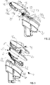
- Figs. 2 and 3 show the cutting head 4 with the comb attachment 10 detached.
- the hair cutting head 4 comprises a cutting head housing 30 made from plastic and a blade unit 5.
- a lower part 34 of said housing 30 is provided as connecting area with the handle 2.
- An upper part 35 of said housing 30 is visible when the cutting head 4 is connected with the handle 2.
- the housing 30 is a hollow part which is closed at its upper end by the stationary blade 6 of the blade unit 5.
- the stationary blade 6 may be made from full metal or plastic with metal teeth. In this case the stationary blade 6 is connected with the cutting head 4 by screws 36 but other connections are possible as well.
- the moveable first blade 7 which cooperates with the cam 32 in order to reciprocate in the direction 8 (see figure 1 ) sideways back and forth relative to the non moveable stationary second blade 6 when in engagement with the eccentric of the motor drive shaft and the motor 3 being operated.
- This movement direction 8 is parallel to a hair cutting edge formed by the tooth tips 6a, 7a of the stationary and / or moveable blade.
- Both blades 6, 7 have a row of hair cutting teeth at its frontal end.
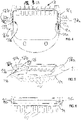
- Figs. 4, 5 and 6 illustrate the comb attachment 10 from different views all with the upper skin contact side shown as the lower side in these Figures.
- This skin contact side 14 is provided with additional multiple protruding hair combing rips 40.
- the comb attachment 10 is formed like a sleeve that is shaped to be sleeved over the cutting head 4 so that the inside coupling side 15 is close or in contact to a skin side 21 of the cutting head 4.
- the comb attachment has a frontal side 13 that is the side which comes first in contact with the hairs to be combed and cut if the device is moved in direction 39 which is an extension of the longitudinal comb teeth 41.
- the comb teeth 41 are aligned in a row and at least partly cover the row of teeth of the blade unit 4. (see fig 1 ).
- lateral sides 16a, 16b Perpendicular to the frontal side 13 with the comb teeth of the comb attachment 10 and laterally to this are provided two lateral sides 16a, 16b with wall portions 18a, 18b. Those wall portions 18a, 18b have insides which face each other and which are each provided with a projection 19a, 19b that serves as the second snap fit connector 11a, 11b.
- the snap fit projections 19a, 19b have a substantially U or V shape in cross section.
- longitudinal rip shaped guide rail projections 20a, 20b In alignment with these snap fit projections 19a, 19b are longitudinal rip shaped guide rail projections 20a, 20b also in provided at the inside of the wall portions 18a, 18b.
- each finger gripping area 17a, 17b On each opposite side of the wall portions 18a, 18b, so not the inside but the outside the lateral sides are each provided with a finger gripping area 17a, 17b.
- This finger gripping area's 17a, 17b may be optionally provided with a structure for enhancing the gripping or may be just flat or without gripping texture.
- the lateral sides 16a, 16b and the wall portions 18a, 18b are substantially rigid. As there is no need for a flexing structure at the second snap fit connector 11a, 11b the lateral sides 16a, 16b adds not much thickness so that he comb attachment is less bulky.
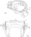
- Figs. 7 and 8 illustrate the housing 30 or part of it of the cutting head 4.
- the cutting head 4 has two lateral sides 24a, 25b each with substantially V- or U- shaped projections that form the first snap fit connector 9a, 9b.
- the snap fit connectors 9a, 9b are supported on a longitudinal tongue 26a, 26b which is connected only at it short sides with the rest of the housing 30.
- slots 27a, 27b at both long sides at each of the tongues 26a, 26b so that the tongues are ease to be flexed and bend when a pushing force substantially in the direction of 29 which is perpendicular to the longitudinal extension of the tongues.
- the upper second slot 27a, 27b is formed by a gap between the first, stationary blade 6 and the tongue 26a, 26b of the housing as can be seen in Fig 2 .
- the first snap fit connector 9a, 9b and its supporting tongue 26a, 26b is located recessed relative to the surrounding housing 30 of the cutting head 4. Further the width extension of the second stationary blade 6 larger than the width extension of the first snap fit connector and the tongue supporting same so that these snap fit parts are also recessed relative to the second blade 6. As a consequence, a groove or indentation 25a, 25b is created in which the first snap fit connector slightly protrudes.
- the comb attachment 10 is attached to the cutting head 4 in the direction 21 which corresponds to the movement direction 39 of the device for trimming hair and which is substantially perpendicular to the reciprocation direction of the first blade and or the hair cutting edge formed by the tooth tips of the blade unit 5.
- the inside 15 of the comb attachment 10 slides on the skin surface 21 of the second blade 6.
- the comb is sleeved over the cutting head 4 by slidingly engaging the projections 19a, 19b of the second snap fit connector and the following guide rail projections 20a, 20b along the grooves or indentations 25a, 25b of the cutting head.
- a slight push of in the direction 21 while holding the comb 10 at the gripping area causes the first snap fit connector 9a, 9b to flex away in direction 29 which is perpendicular to the comb attachment sliding direction 21.
- the grip areas of the comb attachment 10 are substantially rigid and the first snap fit connector of the cutting head is able to flex the finger gripping contact force also in direction 29 is not counteracting or preventing the smooth engagement or disengage of the snap fit connection although the first snap fit connector flexes away in the same direction 29 and at the same area 17a, 17b as the finger's grip the comb attachment 10.
Landscapes
- Life Sciences & Earth Sciences (AREA)
- Forests & Forestry (AREA)
- Engineering & Computer Science (AREA)
- Mechanical Engineering (AREA)
- Dry Shavers And Clippers (AREA)
Abstract

Description
- The invention relates to a hair removal device, in particular an electric shaver or a hair trimmer, comprising: a handle having a motor, a cutting head having a blade unit with a first and second blade for cutting hair, said blade unit being driven by said motor, so that at least one of said first and second blade reciprocates to the other in a reciprocation direction, said cutting head having a first snap fit connector and a comb attachment releasably attachable to the cutting head, said comb attachment having a second snap fit connector provided to engage by snap fit connection with the first snap fit connector for attaching the comb attachment at the cutting head.
- With hair removal devices such as beard trimmers usually the shape and / or the beard hear length may be trimmed. In order to adjust the length of the hair to be cut distance combs are provided which cooperate with a cutting edge and which add more distance between the cutting edge and the skin surface. Other attachments may be used for e.g. assuring that the sharp cutting edge is safely kept away from thin sensible skin areas. Those attachments may be releasably attached to a cutting head of a hair trimmer or an electric shaver and exchanged with each other in accordance with the desired use. The attachments are attached to the cutting head by means of latches, hooks, snap fit or other types.
- It was found that existing snap fit connections suffer from the problem of adding to much bulkiness to the overall dimensions and or are insufficiently easy to handle. Although the snap fit connection per se appears as a rather simple way of connecting parts, those plastic parts to be attached may get broken at those connections first, if this is combined with a required rather unintuitive or cumbersome attachment and detachment of the comb from the cutting head.
- It is an objective underlying the present invention to provide for an improved hair removal device avoiding at least one of the disadvantages of the prior art and/or further developing the existing solutions. A more particular objective underlying the invention is to provide for a hair removal device having an improved snap fit connection between a cutting head and a comb attachment.
- This objective is addressed by a hair removal device, in particular an electric shaver or a hair trimmer, comprising: a handle having a motor , a cutting head having a blade unit with a first and second blade for cutting hair, said blade unit being driven by said motor, so that at least one of said first and second blade reciprocates relative to the other in a reciprocation direction , said cutting head having a first snap fit connector and a comb attachment releasably attachable to the cutting head , said comb attachment having a second snap fit connector provided to engage by snap fit connection with the first snap fit connector for attaching the comb attachment at the cutting head , wherein said first snap fit connector is at least one of: formed in a shape to flex, made of a material to flex or supported to flex, so that said first snap fit connector is able to flex when brought into engagement with said second snap fit connector. A flexing form of said first snap fit connector may be achieved by thinner material thicknesses in the area of the snap fit projection or by an outer shape of the surrounding area which allows flexing. An example of a flexing material is rubber or TPE elastic thermoplastic in the surrounding area of the snap fit or the projection itself. The first snap fit connector may also or alternatively be supported to flex. In this case the snap fit projection may be provided on a wall element that is at least at some sides unconnected to the rest of the housing so that at least one or more slots or free space(s) is/are created adjacent to the snap fit projection. Such lack of connection to other housing parts may e.g. create a flexing tongue onto which the snap fit projection is provided. All those and other possibilities which allow the first snap fit connector to flex may be provided alternatively or in combinations. It is to be noted that such a snap fit connection may be provided with other attachments than a comb attachment. Further, in the context of the invention the terms "first snap fit connector" and second snap fit connector" may refer to at least one of each such first and second snap fit connector but encompasses also two, three or more pairs of first and second snap fit connector (s).
- This arrangement of a flexing first snap fit connector being provided at the cutting head provides several advantages. Usually the provision of flexibility to a snap fit connector increase it thickness or bulkiness in order to allow differentiating between walls which would flex and those which are not desired to flex. The cutting head provided sufficient space for that without adding anything to the dimensions of the comb attachment.
-
- Fig. 1:
- a perspective view of a hair removal device and more particular of a hair trimmer with an attached comb according to the invention,
- Fig. 2:
- a perspective side view of a cutting head with said comb attachment detached from the cutting head in accordance with the hair removal device of
Fig. 1 , - Fig. 3:
- an exploded view of a cutting head with said comb attachment detached from the cutting head in accordance with the hair removal device of
Fig. 1 , - Fig. 4:
- an underside view of said comb attachment in accordance with the hair removal device of
Fig. 1 , - Fig. 5:
- a perspective view of said comb attachment in accordance with the hair removal device of
Fig. 1 , - Fig. 6:
- a backside view said comb attachment in accordance with the hair removal device of
Fig. 1 , - Fig. 7:
- a perspective view of a housing of a cutting head in accordance with the hair removal device of
Fig. 1 , and - Fig. 8:
- a topside view of part of a housing of a cutting head in accordance with the hair removal device of
Fig. 1 . - According to an advantageous aspect, the
comb attachment 10 is provided with at least one row of comb teeth at afrontal side 13, atop skin side 14, an inside hair cutting head coupling side 15 and at least onelateral side 16a, 16b, wherein the at least onelateral side 16a, 16b is provided with a wall portion 18a, 18b that forms a finger gripping area 17a, 17b on the outside and the second snap fit connector 11 on the inside, so that one side of the wall portion is provided with the finger gripping area 17a, 17b and the opposite side of the wall portion 18a, 18b is provided with the second snap fit connector 11a, 11b. Thus the finger grip portion for attaching and detaching the comb onto the cutting head is the same area in which the second snap fit connector is provided (only provided on opposing sides of the same wall portion of the comb attachment). It is usually without adding further design features difficult to release said snap fit connection if at the same time the fingers press at said snap fit connection in order to grip the attachment. - According to another aspect of said hair removal device the
comb attachment 10 is provided with twolateral sides 16a, 16b on opposite sides to each other and with a wall portion 18a, 18b on each of the twolateral sides 16a, 16b, wherein each of the wall portions 18a, 18b is provided with the finger gripping area 17a, 17b on the outside and the second snap fit connector 11a, 11b on the opposing inside. Thus, the comb attachment is not clamped onto the cutting head 4 when the lateral sides are gripped or pressed together in order to detach saidcomb 10. - Said second snap fit connector 11a, 11b is at least one of: formed in a shape, made of a material or supported less flexible than the first snap fit connector 9a, 9b. According to an example for this is the second snap fit connector rigid or non flexible or at least less flexible onto the comb (than compared to the flexibility provided by the material, shape or support of the the first snap fit connector) which enables a slim lateral side design as no additional space is added to the width of the comb for providing a flex structure.
- Moreover, the one or more second snap fit connector 11a, 11b is/are provided with a projection 19a, 19b projecting from the wall portion 18a, 18b and wherein the wall portion 18a, 18b is provided with a guide rail projection 20a, 20b adjacent to and aligned with the projection 19a, 19b of the second snap fit connector 11a, 11b so that both the projection 19a, 19b of the second snap fit connector 11a, 11b and the guide rail projection 20a, 20b serve to guide the
comb attachment 10 at its inner lateral sides during attachment at the cutting head 4. According to an aspect said guide rail projection 20a, 20b is provided on both wall portions of both opposing lateral sides of thecomb attachment 10 independent from whether this term is referred to in singular or plural form, so that preferably next to each of the snap fit projections of the second snap fit connector 11a, 11b is located a rip shaped guide rail projection 20a, 20b. Thus, when attaching thecomb attachment 10 onto the cutting head 4 both the snap fit projection of the second snap fit connector and the guide rail projections serve to guide the comb in a gliding path. - The
comb attachment 10 is provided to be attachable to the cutting head 4 in a direction 21 angled to or perpendicular to thereciprocation direction 8. The direction 21 is set by the aforementioned gliding path along which thecomb attachments 10 glide during attachment. - The cutting head 4 is provided with a top skin side 21, at least one row of teeth 6a, 7a at a
frontal end 23 at each of the first and second blades 6, 7 and at least one lateral side 24a, 24b which is provided with said first snap fit connector 9a, 9b. - According to an aspect of the hair removal device, said cutting head 4 is provided with two opposing lateral sides 24a, 24b wherein each of the lateral sides 24a, 24b is provided with said first snap fit connector 9a, 9b. Having a pair of first snap fit connector 9a, 9b assures safer connection of the comb with the cutting head 4.
- According to another aspect of the hair removal device the at least one lateral side 24a, 24b of the cutting head 4 is provided with an
indentation 25a, 25b and wherein the first snap fit connector 9a, 9b is projecting form saidindentation 25a, 25b. Similar as for the guide rail projection and other features mentioned just in the connection with one side of the cutting head and the comb attachment the other opposing side is provided with the same features, so that when referring just to one of the lateral sides the other side is provided with the same structure independent from singular term form. Thus, the rip of the guide rail projection is guided along the path as defined by the indentation of the cutting head 4. - Further, the hair removal device comprises at least one
indentation 25a, 25b which is shaped as a longitudinal guide groove for guiding the second snap fit connector 11a, 11b during attaching of thecomb attachment 10 at the cutting head 4. The comb attachment and the cutting head are provided with cooperating key and slot structure which allows a guided attachment of thecomb attachment 10 on the cutting head 4 until the first and second snap fit connectors engage with each other. This eases the handling of the attachment and detachment process and avoids a twisting of the snap fit connectors during said process. - According to an aspect the hair removal device is provided with a first snap fit connector 9a, 9b that is/are supported by a flexing tongue 26a, 26b (each). Thus, the first snap fit connector is each supported flexible and/or shaped flexible by flexing tongues.
- Hair removal device according to anyone of the preceding claims, wherein (each of) the first snap fit 9a, 9b connector is surrounded by at least one slot 27a, 27b, in particular by two opposing slots 27a, 27b for allowing the first snap fit connector 9a, 9b to be depressed or move when pushed by the second snap fit connector 11a, 11b during attachment of the
comb attachment 10. Thus the first snap fit connector is provided onto a beam in bending wall portion or a flexing tongue with connections to the cutting head housing at the two opposing short sides and slots 27a, 27b at the two long sides. This assures good flexing properties of the first snap connector without use of a different material component. - The two first snap fit connector 9a, 9b move or flex towards each other during connection of the
comb attachment 10 and more preferably the move or flexdirection 29 of the two first snap fit connector 9a, 9b substantially corresponds to thereciprocation direction 8. It is just the first snap fit connector that substantially move during engagement with the second snap fit connector of the comb attachment. The movement direction of the projection of the first snap fit connector is parallel to or slightly angled to the moveable blade's reciprocation direction. - The first snap fit connector 9a, 9b is one-piece integral with a cutting
head housing 30. Thus, the first snap fit connector is formed by the same part as the cutting head housing which allows a manufacture of this plastic part by an injection molding process. - According to a further aspect a hair removal kit is provided, comprising said hair removal device according and an
other comb attachment 10 releasably attachable to the cutting head 4, said other comb attachment having said (same) second snap fit connector 11a, 11b provided to engage by snap fit connection with the first snap fit connector 9a, 9b for attaching the other comb attachment at the cutting head 4. Accordingly, more comb or other attachments may be provided with a snap fit connecting structure that corresponds to that of thecomb attachment 10 so that different attachments fit to the same snap fit connecting structure of the cutting head 4. -
Fig. 1 shows a perspective view of a body- and/ or beard hear trimmingdevice 1 having ahandle 2, a cutting head 4 which may be releasably connected to the handle or permanently connected to thehandle 2. Thehandle 2 is provided with a on/off button 31 for switching a motor 3 provided inside of thehandle 2 on and off. The motor 3 is provided with a drive shaft having an eccentric which is connectable with a cam 32 (seefigure 3 ) of the cutting head 4. Thehandle 2 may be further provided with arotating wheel 33 or other means for adjusting the hair trimming length. - At its upper end of the cutting head 4 a
comb attachment 10 is releasably attached. The hair trimming length may be adjusted either by said adjustingwheel 33 and/or by attachingdifferent comb attachments 10 to the cutting head which may be provided for specific hair trimming needs or different desired hair cutting lengths. -
Figs. 2 and 3 show the cutting head 4 with thecomb attachment 10 detached. The hair cutting head 4 comprises a cuttinghead housing 30 made from plastic and ablade unit 5. Alower part 34 of saidhousing 30 is provided as connecting area with thehandle 2. Anupper part 35 of saidhousing 30 is visible when the cutting head 4 is connected with thehandle 2. Thehousing 30 is a hollow part which is closed at its upper end by the stationary blade 6 of theblade unit 5. The stationary blade 6 may be made from full metal or plastic with metal teeth. In this case the stationary blade 6 is connected with the cutting head 4 by screws 36 but other connections are possible as well. - Another part of the
blade unit 5 is the moveable first blade 7 which cooperates with thecam 32 in order to reciprocate in the direction 8 (seefigure 1 ) sideways back and forth relative to the non moveable stationary second blade 6 when in engagement with the eccentric of the motor drive shaft and the motor 3 being operated. Thismovement direction 8 is parallel to a hair cutting edge formed by the tooth tips 6a, 7a of the stationary and / or moveable blade. Both blades 6, 7 have a row of hair cutting teeth at its frontal end. -
Figs. 4, 5 and 6 illustrate thecomb attachment 10 from different views all with the upper skin contact side shown as the lower side in these Figures. Thisskin contact side 14 is provided with additional multiple protruding hair combing rips 40. - The
comb attachment 10 is formed like a sleeve that is shaped to be sleeved over the cutting head 4 so that the inside coupling side 15 is close or in contact to a skin side 21 of the cutting head 4. The comb attachment has afrontal side 13 that is the side which comes first in contact with the hairs to be combed and cut if the device is moved indirection 39 which is an extension of the longitudinal comb teeth 41. The comb teeth 41 are aligned in a row and at least partly cover the row of teeth of the blade unit 4. (seefig 1 ). - Perpendicular to the
frontal side 13 with the comb teeth of thecomb attachment 10 and laterally to this are provided twolateral sides 16a, 16b with wall portions 18a, 18b. Those wall portions 18a, 18b have insides which face each other and which are each provided with a projection 19a, 19b that serves as the second snap fit connector 11a, 11b. The snap fit projections 19a, 19b have a substantially U or V shape in cross section. In alignment with these snap fit projections 19a, 19b are longitudinal rip shaped guide rail projections 20a, 20b also in provided at the inside of the wall portions 18a, 18b. On each opposite side of the wall portions 18a, 18b, so not the inside but the outside the lateral sides are each provided with a finger gripping area 17a, 17b. This finger gripping area's 17a, 17b may be optionally provided with a structure for enhancing the gripping or may be just flat or without gripping texture. Thelateral sides 16a, 16b and the wall portions 18a, 18b are substantially rigid. As there is no need for a flexing structure at the second snap fit connector 11a, 11b thelateral sides 16a, 16b adds not much thickness so that he comb attachment is less bulky. -
Figs. 7 and 8 illustrate thehousing 30 or part of it of the cutting head 4. The cutting head 4 has two lateral sides 24a, 25b each with substantially V- or U- shaped projections that form the first snap fit connector 9a, 9b. The snap fit connectors 9a, 9b are supported on a longitudinal tongue 26a, 26b which is connected only at it short sides with the rest of thehousing 30. Thus there are slots 27a, 27b at both long sides at each of the tongues 26a, 26b so that the tongues are ease to be flexed and bend when a pushing force substantially in the direction of 29 which is perpendicular to the longitudinal extension of the tongues. This flexing assures that both first and second snap fit connectors are able to engage and disengage from each other during attachment and detachment of thecomb 10. The upper second slot 27a, 27b is formed by a gap between the first, stationary blade 6 and the tongue 26a, 26b of the housing as can be seen inFig 2 . - As illustrated by
Figs 7 and 8 the first snap fit connector 9a, 9b and its supporting tongue 26a, 26b is located recessed relative to the surroundinghousing 30 of the cutting head 4. Further the width extension of the second stationary blade 6 larger than the width extension of the first snap fit connector and the tongue supporting same so that these snap fit parts are also recessed relative to the second blade 6. As a consequence, a groove orindentation 25a, 25b is created in which the first snap fit connector slightly protrudes. - The
comb attachment 10 is attached to the cutting head 4 in the direction 21 which corresponds to themovement direction 39 of the device for trimming hair and which is substantially perpendicular to the reciprocation direction of the first blade and or the hair cutting edge formed by the tooth tips of theblade unit 5. When sliding thecomb attachment 10 onto the cutting head 4 the inside 15 of thecomb attachment 10 slides on the skin surface 21 of the second blade 6. Further on the lateral sides of the comb attachment the comb is sleeved over the cutting head 4 by slidingly engaging the projections 19a, 19b of the second snap fit connector and the following guide rail projections 20a, 20b along the grooves orindentations 25a, 25b of the cutting head. A slight push of in the direction 21 while holding thecomb 10 at the gripping area causes the first snap fit connector 9a, 9b to flex away indirection 29 which is perpendicular to the comb attachment sliding direction 21. As the grip areas of thecomb attachment 10 are substantially rigid and the first snap fit connector of the cutting head is able to flex the finger gripping contact force also indirection 29 is not counteracting or preventing the smooth engagement or disengage of the snap fit connection although the first snap fit connector flexes away in thesame direction 29 and at the same area 17a, 17b as the finger's grip thecomb attachment 10. - The dimensions and values disclosed herein are not to be understood as being strictly limited to the exact numerical values recited. Instead, unless otherwise specified, each such dimension is intended to mean both the recited value and a functionally equivalent range surrounding that value. For example, a dimension disclosed as "40 mm" is intended to mean "about 40 mm."
Claims (15)
- Hair removal device, in particular an electric shaver or a hair trimmer, comprising:- a handle (2) having a motor (3),- a cutting head (4) having a blade unit (5) with a first and second blade (6, 7) for cutting hair, said blade unit (5) being driven by said motor (3), so that at least one of said first and second blade (6, 7) reciprocates relative to the other in a reciprocation direction (8), said cutting head (4) having a first snap fit connector (9a, 9b) and- a comb attachment (10) releasably attachable to the cutting head (4), said comb attachment (10) having a second snap fit connector (11a, 11b) provided to engage by snap fit connection with the first snap fit connector (9a, 9b) for attaching the comb attachment (10) at the cutting head (4), wherein,- said first snap fit connector (9a, 9b) is at least one of: formed in a shape to flex, made of a material to flex or supported to flex, so that said first snap fit connector (9a, 9b) is able to flex when brought into engagement with said second snap fit connector (11a, 11b).
- Hair removal device of claim 1, wherein the comb attachment (10) is provided with at least one row of comb teeth (12) at a frontal side (13), a top skin side (14), an inside hair cutting head coupling side (15) and at least one lateral side (16a, 16b), wherein the at least one lateral side (16a, 16b) is provided with a wall portion (18a, 18b) that forms a finger gripping area (17a, 17b) on the outside and the second snap fit connector (11a, 11b) on the inside, so that one side of the wall portion is provided with the finger gripping area (17a, 17b) and the opposite side of the wall portion (18a, 18b) is provided with the second snap fit connector (11a, 11b).
- Hair removal device according to claim 2, wherein the comb attachment (10) is provided with two lateral sides (16a, 16b) on opposite sides to each other and with a wall portion (18a, 18b) on each of the two lateral sides (16a, 16b), wherein each of the wall portions (18a, 18b) is provided with the finger gripping area (17a, 17b) on the outside and the second snap fit connector (11a, 11b) on the opposing inside.
- Hair removal device according to anyone of the preceding claims, wherein said second snap fit connector (11a, 11b) is at least one of: formed in a shape, made of a material or supported less flexible than the first snap fit connector (9a, 9b).
- Hair removal device according to anyone of claims 2 or 3, wherein the one or more second snap fit connector (11a, 11b) is provided with a projection (19a, 19b) projecting from the wall portion (18a, 18b) and wherein the wall portion (18a, 18b) is provided with a guide rail projection (20a, 20b) adjacent to and aligned with the projection (19a, 19b) of the second snap fit connector (11a, 11b) so that both the projection (19a, 19b) of the second snap fit connector (11a, 11b) and the guide rail projection (20a, 20b) serve to guide the comb attachment (10) at its inner lateral sides during attachment at the cutting head (4).
- Hair removal device according to anyone of the preceding claims, wherein the comb attachment (10) is provided to be attachable to the cutting head (4) in a direction angled to or perpendicular to the reciprocation direction (8).
- Hair removal device according to anyone of the preceding claims, wherein the cutting head (4) is provided with a top skin side (21), at least one row of teeth (6a, 7a) at a frontal end (23) at each of the first and second blades (6, 7) and at least one lateral side (24a, 24b) which is provided with said first snap fit connector (9a, 9b).
- Hair removal device according to the preceding claim, wherein said cutting head (4) is provided with two opposing lateral sides (24a, 24b) wherein each of the lateral sides (24a, 24b) is provided with said first snap fit connector (9a, 9b).
- Hair removal device according to anyone of the preceding claims 7 or 8, wherein the at least one lateral side (24a, 24b) of the cutting head (4) is provided with an indentation (25a, 25b) and wherein the first snap fit connector (9a, 9b) is projecting form said indentation (25a, 25b).
- Hair removal device according to the preceding claim, wherein said at least one indentation (25a, 25b) is shaped as a longitudinal guide groove for guiding the second snap fit connector (11a, 11b) during attaching of the comb attachment (10) at the cutting head (4).
- Hair removal device according to anyone of the preceding claims, wherein the first snap fit connector (9a, 9b) is supported by a flexing tongue (26a, 26b).
- Hair removal device according to anyone of the preceding claims, wherein the first snap fit (9a, 9b) connector is surrounded by at least one slot (27a, 27b) , in particular by two opposing slots (27a, 27b) for allowing the first snap fit connector (9a, 9b) to be depressed or move when pushed by the second snap fit connector (11a, 11b) during attachment of the comb attachment (10).
- Hair removal device according to any of the preceding claims 8-12, wherein the two first snap fit connector (9a, 9b) move or flex towards each other during connection of the comb attachment (10) and more preferably the move or flex direction (29) of the two first snap fit connector (9a, 9b) substantially corresponds to the reciprocation direction (8).
- Hair removal device according to anyone of the preceding claims, wherein the first snap fit connector (9a, 9b) is one piece integral with a cutting head housing (30).
- Hair removal kit comprising a hair removal device according to anyone of the preceding claims and an other comb attachment (10) releasably attachable to the cutting head (4), said other comb attachment having said second snap fit connector (11a, 11b) provided to engage by snap fit connection with the first snap fit connector (9a, 9b) for attaching the other comb attachment at the cutting head (4).
Priority Applications (5)
| Application Number | Priority Date | Filing Date | Title |
|---|---|---|---|
| EP21182056.8A EP4112249B1 (en) | 2021-06-28 | 2021-06-28 | Hair removal device |
| US17/850,789 US12240133B2 (en) | 2021-06-28 | 2022-06-27 | Hair removal device |
| PCT/IB2022/055996 WO2023275745A1 (en) | 2021-06-28 | 2022-06-28 | Hair removal device |
| CN202280044557.8A CN117561147B (en) | 2021-06-28 | 2022-06-28 | Hair removing device |
| JP2023579743A JP7708897B2 (en) | 2021-06-28 | 2022-06-28 | Hair removal device |
Applications Claiming Priority (1)
| Application Number | Priority Date | Filing Date | Title |
|---|---|---|---|
| EP21182056.8A EP4112249B1 (en) | 2021-06-28 | 2021-06-28 | Hair removal device |
Publications (2)
| Publication Number | Publication Date |
|---|---|
| EP4112249A1 true EP4112249A1 (en) | 2023-01-04 |
| EP4112249B1 EP4112249B1 (en) | 2025-03-19 |
Family
ID=76695581
Family Applications (1)
| Application Number | Title | Priority Date | Filing Date |
|---|---|---|---|
| EP21182056.8A Active EP4112249B1 (en) | 2021-06-28 | 2021-06-28 | Hair removal device |
Country Status (5)
| Country | Link |
|---|---|
| US (1) | US12240133B2 (en) |
| EP (1) | EP4112249B1 (en) |
| JP (1) | JP7708897B2 (en) |
| CN (1) | CN117561147B (en) |
| WO (1) | WO2023275745A1 (en) |
Families Citing this family (10)
| Publication number | Priority date | Publication date | Assignee | Title |
|---|---|---|---|---|
| US12403619B2 (en) * | 2008-11-24 | 2025-09-02 | Lonnie Andrew Holmes | Hair clippers with flexing electrically adjustable blades |
| USD922684S1 (en) * | 2019-01-24 | 2021-06-15 | Braun Gmbh | Part of a hair removal device |
| CN112112873B (en) * | 2020-10-28 | 2025-05-30 | 湖北亿纬动力有限公司 | Connecting rivet and battery module |
| EP4112245B1 (en) * | 2021-06-28 | 2025-10-22 | Braun GmbH | Hair cutting kit |
| USD991559S1 (en) * | 2022-03-09 | 2023-07-04 | Shenzhen Early Century Technology Co., Ltd. | Rotary guide comb |
| USD1045226S1 (en) * | 2022-07-27 | 2024-10-01 | E. Mishan & Sons, Inc. | Vacuum shaver |
| US20240066730A1 (en) * | 2022-08-24 | 2024-02-29 | Abdulaziz Esmaeel Al-Ansari | Adjustable-taper comb attachment for a hair clipper |
| USD1035151S1 (en) * | 2022-12-21 | 2024-07-09 | Ningbo VGR Electric Appliance Co., Ltd. | Hair clipper |
| USD1035150S1 (en) * | 2023-01-17 | 2024-07-09 | Ningbo VGR Electric Appliance Co., Ltd. | Hair clipper |
| USD1106582S1 (en) * | 2023-11-07 | 2025-12-16 | Wenzhou Ante Electrical Appliance Co., Ltd. | Hair clipper |
Citations (5)
| Publication number | Priority date | Publication date | Assignee | Title |
|---|---|---|---|---|
| EP0176372A1 (en) * | 1984-09-28 | 1986-04-02 | Wahl Clipper Corporation | Hair trimming apparatus |
| DE3623591A1 (en) * | 1986-07-12 | 1988-01-21 | Moser Gmbh Kuno | HAIRCUTTER WITH CUTTING LENGTH ADJUSTMENT |
| US5259115A (en) * | 1991-12-17 | 1993-11-09 | Braun Aktiengesellschaft | Electric hair cutting apparatus |
| US20030056374A1 (en) * | 2001-09-25 | 2003-03-27 | Wahl Clipper Corporation | Color-coded attachment comb key for hair clipper |
| EP1632321A1 (en) * | 2004-09-01 | 2006-03-08 | Matsushita Electric Works, Ltd. | Comb-vibration preventing structure for hair cutter |
Family Cites Families (10)
| Publication number | Priority date | Publication date | Assignee | Title |
|---|---|---|---|---|
| JP2544756B2 (en) * | 1987-08-13 | 1996-10-16 | 松下電工株式会社 | Hair cutter |
| JP4466077B2 (en) * | 2003-12-26 | 2010-05-26 | パナソニック電工株式会社 | Hair cutter |
| EP2322328A1 (en) * | 2009-11-17 | 2011-05-18 | Koninklijke Philips Electronics N.V. | Hair cutting device with comb unit recognition |
| WO2014090429A1 (en) * | 2012-12-10 | 2014-06-19 | Koninkluke Philips N.V. | A hair trimming device |
| RU2682358C2 (en) * | 2015-02-26 | 2019-03-19 | Конинклейке Филипс Н.В. | Attachment comb and hair cutting appliance |
| RU2727487C2 (en) * | 2015-08-04 | 2020-07-21 | Конинклейке Филипс Н.В. | Hair container and set for hair clipper |
| ES2904600T3 (en) * | 2016-01-12 | 2022-04-05 | Koninklijke Philips Nv | Length adjustment mechanism for a hair cutting apparatus |
| CN206277422U (en) * | 2016-11-16 | 2017-06-27 | 杨海江 | A kind of hair scissors limiting comb adjustment structure |
| US12233563B2 (en) * | 2022-08-16 | 2025-02-25 | Wahl Clipper Corporation | Hair clipper attachment comb with enhanced hair flow geometry |
| EP4331788A1 (en) * | 2022-08-30 | 2024-03-06 | Braun GmbH | An electric hair removal device, a kit and an attachment |
-
2021
- 2021-06-28 EP EP21182056.8A patent/EP4112249B1/en active Active
-
2022
- 2022-06-27 US US17/850,789 patent/US12240133B2/en active Active
- 2022-06-28 CN CN202280044557.8A patent/CN117561147B/en active Active
- 2022-06-28 WO PCT/IB2022/055996 patent/WO2023275745A1/en not_active Ceased
- 2022-06-28 JP JP2023579743A patent/JP7708897B2/en active Active
Patent Citations (5)
| Publication number | Priority date | Publication date | Assignee | Title |
|---|---|---|---|---|
| EP0176372A1 (en) * | 1984-09-28 | 1986-04-02 | Wahl Clipper Corporation | Hair trimming apparatus |
| DE3623591A1 (en) * | 1986-07-12 | 1988-01-21 | Moser Gmbh Kuno | HAIRCUTTER WITH CUTTING LENGTH ADJUSTMENT |
| US5259115A (en) * | 1991-12-17 | 1993-11-09 | Braun Aktiengesellschaft | Electric hair cutting apparatus |
| US20030056374A1 (en) * | 2001-09-25 | 2003-03-27 | Wahl Clipper Corporation | Color-coded attachment comb key for hair clipper |
| EP1632321A1 (en) * | 2004-09-01 | 2006-03-08 | Matsushita Electric Works, Ltd. | Comb-vibration preventing structure for hair cutter |
Also Published As
| Publication number | Publication date |
|---|---|
| CN117561147B (en) | 2026-07-28 |
| US12240133B2 (en) | 2025-03-04 |
| JP7708897B2 (en) | 2025-07-15 |
| CN117561147A (en) | 2024-02-13 |
| US20220410420A1 (en) | 2022-12-29 |
| EP4112249B1 (en) | 2025-03-19 |
| JP2024523590A (en) | 2024-06-28 |
| WO2023275745A1 (en) | 2023-01-05 |
Similar Documents
| Publication | Publication Date | Title |
|---|---|---|
| EP4112249B1 (en) | Hair removal device | |
| JP3601092B2 (en) | Hair cutter | |
| KR100803865B1 (en) | Hair clippers | |
| US10226873B2 (en) | Hair cutting appliance, receptacle and connector plug | |
| AU2015246185B2 (en) | Blade set, hair cutting appliance, and related manufacturing method | |
| CN205735054U (en) | Cutting heads and hair cutting appliances | |
| CN204658474U (en) | Haircut appliance and set of blades | |
| CN206011158U (en) | releasable attachment comb and cutting head | |
| US10647010B2 (en) | Blade set, hair cutting appliance, and related manufacturing method | |
| CN109079862B (en) | Hair cutting system and accessory | |
| US5054199A (en) | Hair cutter | |
| EP0886563B1 (en) | Hair-cutting system including a hair-cutting apparatus and including a comb device which can be mounted onto the apparatus and which has two spring-loaded comb sections | |
| EP2465652B1 (en) | Hair cutter | |
| EP0885094A1 (en) | Hair-cutting system including a hair-cutting apparatus having an adjustment button and an on/off button | |
| EP3785869A1 (en) | Electric hair trimmer | |
| US4233733A (en) | Electric shaver | |
| US5123159A (en) | Hair clipper | |
| US20220314470A1 (en) | Comb-shaped outer blade, blade unit, and electric razor | |
| CN115723178A (en) | Comb for hair cutting device | |
| US20220314473A1 (en) | Blade unit and electric razor | |
| US4131995A (en) | Smoothing comb for a hair trimmer | |
| WO2006051620A1 (en) | Electric clipper head assembly | |
| JP2002273072A (en) | Electric razor | |
| JP2013126439A (en) | Electric razor | |
| JP2013126437A (en) | Electric razor |
Legal Events
| Date | Code | Title | Description |
|---|---|---|---|
| PUAI | Public reference made under article 153(3) epc to a published international application that has entered the european phase |
Free format text: ORIGINAL CODE: 0009012 |
|
| STAA | Information on the status of an ep patent application or granted ep patent |
Free format text: STATUS: THE APPLICATION HAS BEEN PUBLISHED |
|
| AK | Designated contracting states |
Kind code of ref document: A1 Designated state(s): AL AT BE BG CH CY CZ DE DK EE ES FI FR GB GR HR HU IE IS IT LI LT LU LV MC MK MT NL NO PL PT RO RS SE SI SK SM TR |
|
| P01 | Opt-out of the competence of the unified patent court (upc) registered |
Effective date: 20230430 |
|
| STAA | Information on the status of an ep patent application or granted ep patent |
Free format text: STATUS: REQUEST FOR EXAMINATION WAS MADE |
|
| 17P | Request for examination filed |
Effective date: 20230928 |
|
| RBV | Designated contracting states (corrected) |
Designated state(s): AL AT BE BG CH CY CZ DE DK EE ES FI FR GB GR HR HU IE IS IT LI LT LU LV MC MK MT NL NO PL PT RO RS SE SI SK SM TR |
|
| GRAP | Despatch of communication of intention to grant a patent |
Free format text: ORIGINAL CODE: EPIDOSNIGR1 |
|
| STAA | Information on the status of an ep patent application or granted ep patent |
Free format text: STATUS: GRANT OF PATENT IS INTENDED |
|
| INTG | Intention to grant announced |
Effective date: 20241008 |
|
| GRAS | Grant fee paid |
Free format text: ORIGINAL CODE: EPIDOSNIGR3 |
|
| GRAA | (expected) grant |
Free format text: ORIGINAL CODE: 0009210 |
|
| STAA | Information on the status of an ep patent application or granted ep patent |
Free format text: STATUS: THE PATENT HAS BEEN GRANTED |
|
| AK | Designated contracting states |
Kind code of ref document: B1 Designated state(s): AL AT BE BG CH CY CZ DE DK EE ES FI FR GB GR HR HU IE IS IT LI LT LU LV MC MK MT NL NO PL PT RO RS SE SI SK SM TR |
|
| REG | Reference to a national code |
Ref country code: GB Ref legal event code: FG4D |
|
| REG | Reference to a national code |
Ref country code: CH Ref legal event code: EP |
|
| REG | Reference to a national code |
Ref country code: IE Ref legal event code: FG4D |
|
| REG | Reference to a national code |
Ref country code: DE Ref legal event code: R096 Ref document number: 602021027710 Country of ref document: DE |
|
| REG | Reference to a national code |
Ref country code: NL Ref legal event code: FP |
|
| PG25 | Lapsed in a contracting state [announced via postgrant information from national office to epo] |
Ref country code: RS Free format text: LAPSE BECAUSE OF FAILURE TO SUBMIT A TRANSLATION OF THE DESCRIPTION OR TO PAY THE FEE WITHIN THE PRESCRIBED TIME-LIMIT Effective date: 20250619 |
|
| PG25 | Lapsed in a contracting state [announced via postgrant information from national office to epo] |
Ref country code: FI Free format text: LAPSE BECAUSE OF FAILURE TO SUBMIT A TRANSLATION OF THE DESCRIPTION OR TO PAY THE FEE WITHIN THE PRESCRIBED TIME-LIMIT Effective date: 20250319 |
|
| REG | Reference to a national code |
Ref country code: LT Ref legal event code: MG9D |
|
| PG25 | Lapsed in a contracting state [announced via postgrant information from national office to epo] |
Ref country code: NO Free format text: LAPSE BECAUSE OF FAILURE TO SUBMIT A TRANSLATION OF THE DESCRIPTION OR TO PAY THE FEE WITHIN THE PRESCRIBED TIME-LIMIT Effective date: 20250619 |
|
| PG25 | Lapsed in a contracting state [announced via postgrant information from national office to epo] |
Ref country code: HR Free format text: LAPSE BECAUSE OF FAILURE TO SUBMIT A TRANSLATION OF THE DESCRIPTION OR TO PAY THE FEE WITHIN THE PRESCRIBED TIME-LIMIT Effective date: 20250319 |
|
| PG25 | Lapsed in a contracting state [announced via postgrant information from national office to epo] |
Ref country code: LV Free format text: LAPSE BECAUSE OF FAILURE TO SUBMIT A TRANSLATION OF THE DESCRIPTION OR TO PAY THE FEE WITHIN THE PRESCRIBED TIME-LIMIT Effective date: 20250319 |
|
| PG25 | Lapsed in a contracting state [announced via postgrant information from national office to epo] |
Ref country code: GR Free format text: LAPSE BECAUSE OF FAILURE TO SUBMIT A TRANSLATION OF THE DESCRIPTION OR TO PAY THE FEE WITHIN THE PRESCRIBED TIME-LIMIT Effective date: 20250620 Ref country code: BG Free format text: LAPSE BECAUSE OF FAILURE TO SUBMIT A TRANSLATION OF THE DESCRIPTION OR TO PAY THE FEE WITHIN THE PRESCRIBED TIME-LIMIT Effective date: 20250319 |
|
| REG | Reference to a national code |
Ref country code: AT Ref legal event code: MK05 Ref document number: 1776606 Country of ref document: AT Kind code of ref document: T Effective date: 20250319 |
|
| PG25 | Lapsed in a contracting state [announced via postgrant information from national office to epo] |
Ref country code: SE Free format text: LAPSE BECAUSE OF FAILURE TO SUBMIT A TRANSLATION OF THE DESCRIPTION OR TO PAY THE FEE WITHIN THE PRESCRIBED TIME-LIMIT Effective date: 20250319 |
|
| PG25 | Lapsed in a contracting state [announced via postgrant information from national office to epo] |
Ref country code: SM Free format text: LAPSE BECAUSE OF FAILURE TO SUBMIT A TRANSLATION OF THE DESCRIPTION OR TO PAY THE FEE WITHIN THE PRESCRIBED TIME-LIMIT Effective date: 20250319 |
|
| PG25 | Lapsed in a contracting state [announced via postgrant information from national office to epo] |
Ref country code: ES Free format text: LAPSE BECAUSE OF FAILURE TO SUBMIT A TRANSLATION OF THE DESCRIPTION OR TO PAY THE FEE WITHIN THE PRESCRIBED TIME-LIMIT Effective date: 20250319 Ref country code: PT Free format text: LAPSE BECAUSE OF FAILURE TO SUBMIT A TRANSLATION OF THE DESCRIPTION OR TO PAY THE FEE WITHIN THE PRESCRIBED TIME-LIMIT Effective date: 20250721 |
|
| PG25 | Lapsed in a contracting state [announced via postgrant information from national office to epo] |
Ref country code: IT Free format text: LAPSE BECAUSE OF FAILURE TO SUBMIT A TRANSLATION OF THE DESCRIPTION OR TO PAY THE FEE WITHIN THE PRESCRIBED TIME-LIMIT Effective date: 20250319 Ref country code: PL Free format text: LAPSE BECAUSE OF FAILURE TO SUBMIT A TRANSLATION OF THE DESCRIPTION OR TO PAY THE FEE WITHIN THE PRESCRIBED TIME-LIMIT Effective date: 20250319 |
|
| PG25 | Lapsed in a contracting state [announced via postgrant information from national office to epo] |
Ref country code: AT Free format text: LAPSE BECAUSE OF FAILURE TO SUBMIT A TRANSLATION OF THE DESCRIPTION OR TO PAY THE FEE WITHIN THE PRESCRIBED TIME-LIMIT Effective date: 20250319 |
|
| PG25 | Lapsed in a contracting state [announced via postgrant information from national office to epo] |
Ref country code: CZ Free format text: LAPSE BECAUSE OF FAILURE TO SUBMIT A TRANSLATION OF THE DESCRIPTION OR TO PAY THE FEE WITHIN THE PRESCRIBED TIME-LIMIT Effective date: 20250319 Ref country code: EE Free format text: LAPSE BECAUSE OF FAILURE TO SUBMIT A TRANSLATION OF THE DESCRIPTION OR TO PAY THE FEE WITHIN THE PRESCRIBED TIME-LIMIT Effective date: 20250319 |
|
| PG25 | Lapsed in a contracting state [announced via postgrant information from national office to epo] |
Ref country code: RO Free format text: LAPSE BECAUSE OF FAILURE TO SUBMIT A TRANSLATION OF THE DESCRIPTION OR TO PAY THE FEE WITHIN THE PRESCRIBED TIME-LIMIT Effective date: 20250319 |
|
| PG25 | Lapsed in a contracting state [announced via postgrant information from national office to epo] |
Ref country code: SK Free format text: LAPSE BECAUSE OF FAILURE TO SUBMIT A TRANSLATION OF THE DESCRIPTION OR TO PAY THE FEE WITHIN THE PRESCRIBED TIME-LIMIT Effective date: 20250319 |
|
| PG25 | Lapsed in a contracting state [announced via postgrant information from national office to epo] |
Ref country code: IS Free format text: LAPSE BECAUSE OF FAILURE TO SUBMIT A TRANSLATION OF THE DESCRIPTION OR TO PAY THE FEE WITHIN THE PRESCRIBED TIME-LIMIT Effective date: 20250719 |
|
| REG | Reference to a national code |
Ref country code: DE Ref legal event code: R097 Ref document number: 602021027710 Country of ref document: DE |
|
| PG25 | Lapsed in a contracting state [announced via postgrant information from national office to epo] |
Ref country code: DK Free format text: LAPSE BECAUSE OF FAILURE TO SUBMIT A TRANSLATION OF THE DESCRIPTION OR TO PAY THE FEE WITHIN THE PRESCRIBED TIME-LIMIT Effective date: 20250319 |
|
| PLBE | No opposition filed within time limit |
Free format text: ORIGINAL CODE: 0009261 |
|
| STAA | Information on the status of an ep patent application or granted ep patent |
Free format text: STATUS: NO OPPOSITION FILED WITHIN TIME LIMIT |
|
| REG | Reference to a national code |
Ref country code: CH Ref legal event code: H13 Free format text: ST27 STATUS EVENT CODE: U-0-0-H10-H13 (AS PROVIDED BY THE NATIONAL OFFICE) Effective date: 20260127 |
|
| REG | Reference to a national code |
Ref country code: CH Ref legal event code: L10 Free format text: ST27 STATUS EVENT CODE: U-0-0-L10-L00 (AS PROVIDED BY THE NATIONAL OFFICE) Effective date: 20260128 |
|
| PG25 | Lapsed in a contracting state [announced via postgrant information from national office to epo] |
Ref country code: MC Free format text: LAPSE BECAUSE OF FAILURE TO SUBMIT A TRANSLATION OF THE DESCRIPTION OR TO PAY THE FEE WITHIN THE PRESCRIBED TIME-LIMIT Effective date: 20250319 |
|
| PG25 | Lapsed in a contracting state [announced via postgrant information from national office to epo] |
Ref country code: LU Free format text: LAPSE BECAUSE OF NON-PAYMENT OF DUE FEES Effective date: 20250628 |
|
| 26N | No opposition filed |
Effective date: 20251222 |
|
| REG | Reference to a national code |
Ref country code: BE Ref legal event code: MM Effective date: 20250630 |
|
| PG25 | Lapsed in a contracting state [announced via postgrant information from national office to epo] |
Ref country code: IE Free format text: LAPSE BECAUSE OF NON-PAYMENT OF DUE FEES Effective date: 20250628 |
|
| PG25 | Lapsed in a contracting state [announced via postgrant information from national office to epo] |
Ref country code: BE Free format text: LAPSE BECAUSE OF NON-PAYMENT OF DUE FEES Effective date: 20250630 |
|
| PG25 | Lapsed in a contracting state [announced via postgrant information from national office to epo] |
Ref country code: CH Free format text: LAPSE BECAUSE OF NON-PAYMENT OF DUE FEES Effective date: 20250630 |
|
| PGFP | Annual fee paid to national office [announced via postgrant information from national office to epo] |
Ref country code: NL Payment date: 20260514 Year of fee payment: 6 |
|
| PG25 | Lapsed in a contracting state [announced via postgrant information from national office to epo] |
Ref country code: LT Free format text: LAPSE BECAUSE OF FAILURE TO SUBMIT A TRANSLATION OF THE DESCRIPTION OR TO PAY THE FEE WITHIN THE PRESCRIBED TIME-LIMIT Effective date: 20250319 |
|
| PGFP | Annual fee paid to national office [announced via postgrant information from national office to epo] |
Ref country code: GB Payment date: 20260511 Year of fee payment: 6 |
|
| PGFP | Annual fee paid to national office [announced via postgrant information from national office to epo] |
Ref country code: DE Payment date: 20260506 Year of fee payment: 6 |
|
| PGFP | Annual fee paid to national office [announced via postgrant information from national office to epo] |
Ref country code: FR Payment date: 20260511 Year of fee payment: 6 |
|
| PG25 | Lapsed in a contracting state [announced via postgrant information from national office to epo] |
Ref country code: CY Free format text: LAPSE BECAUSE OF FAILURE TO SUBMIT A TRANSLATION OF THE DESCRIPTION OR TO PAY THE FEE WITHIN THE PRESCRIBED TIME-LIMIT Effective date: 20250319 |