EP4112219A1 - Guide wire - Google Patents
Guide wire Download PDFInfo
- Publication number
- EP4112219A1 EP4112219A1 EP21781029.0A EP21781029A EP4112219A1 EP 4112219 A1 EP4112219 A1 EP 4112219A1 EP 21781029 A EP21781029 A EP 21781029A EP 4112219 A1 EP4112219 A1 EP 4112219A1
- Authority
- EP
- European Patent Office
- Prior art keywords
- wire
- outer diameter
- joint surface
- joining
- particle size
- Prior art date
- Legal status (The legal status is an assumption and is not a legal conclusion. Google has not performed a legal analysis and makes no representation as to the accuracy of the status listed.)
- Pending
Links
Images


Classifications
-
- A—HUMAN NECESSITIES
- A61—MEDICAL OR VETERINARY SCIENCE; HYGIENE
- A61M—DEVICES FOR INTRODUCING MEDIA INTO, OR ONTO, THE BODY; DEVICES FOR TRANSDUCING BODY MEDIA OR FOR TAKING MEDIA FROM THE BODY; DEVICES FOR PRODUCING OR ENDING SLEEP OR STUPOR
- A61M25/00—Catheters; Hollow probes
- A61M25/01—Introducing, guiding, advancing, emplacing or holding catheters
- A61M25/09—Guide wires
-
- B—PERFORMING OPERATIONS; TRANSPORTING
- B23—MACHINE TOOLS; METAL-WORKING NOT OTHERWISE PROVIDED FOR
- B23K—SOLDERING OR UNSOLDERING; WELDING; CLADDING OR PLATING BY SOLDERING OR WELDING; CUTTING BY APPLYING HEAT LOCALLY, e.g. FLAME CUTTING; WORKING BY LASER BEAM
- B23K20/00—Non-electric welding by applying impact or other pressure, with or without the application of heat, e.g. cladding or plating
- B23K20/002—Non-electric welding by applying impact or other pressure, with or without the application of heat, e.g. cladding or plating specially adapted for particular articles or work
- B23K20/004—Wire welding
-
- B—PERFORMING OPERATIONS; TRANSPORTING
- B23—MACHINE TOOLS; METAL-WORKING NOT OTHERWISE PROVIDED FOR
- B23K—SOLDERING OR UNSOLDERING; WELDING; CLADDING OR PLATING BY SOLDERING OR WELDING; CUTTING BY APPLYING HEAT LOCALLY, e.g. FLAME CUTTING; WORKING BY LASER BEAM
- B23K20/00—Non-electric welding by applying impact or other pressure, with or without the application of heat, e.g. cladding or plating
- B23K20/02—Non-electric welding by applying impact or other pressure, with or without the application of heat, e.g. cladding or plating by means of a press ; Diffusion bonding
- B23K20/023—Thermo-compression bonding
-
- B—PERFORMING OPERATIONS; TRANSPORTING
- B23—MACHINE TOOLS; METAL-WORKING NOT OTHERWISE PROVIDED FOR
- B23K—SOLDERING OR UNSOLDERING; WELDING; CLADDING OR PLATING BY SOLDERING OR WELDING; CUTTING BY APPLYING HEAT LOCALLY, e.g. FLAME CUTTING; WORKING BY LASER BEAM
- B23K20/00—Non-electric welding by applying impact or other pressure, with or without the application of heat, e.g. cladding or plating
- B23K20/06—Non-electric welding by applying impact or other pressure, with or without the application of heat, e.g. cladding or plating by means of high energy impulses, e.g. magnetic energy
-
- B—PERFORMING OPERATIONS; TRANSPORTING
- B23—MACHINE TOOLS; METAL-WORKING NOT OTHERWISE PROVIDED FOR
- B23K—SOLDERING OR UNSOLDERING; WELDING; CLADDING OR PLATING BY SOLDERING OR WELDING; CUTTING BY APPLYING HEAT LOCALLY, e.g. FLAME CUTTING; WORKING BY LASER BEAM
- B23K20/00—Non-electric welding by applying impact or other pressure, with or without the application of heat, e.g. cladding or plating
- B23K20/06—Non-electric welding by applying impact or other pressure, with or without the application of heat, e.g. cladding or plating by means of high energy impulses, e.g. magnetic energy
- B23K20/08—Explosive welding
-
- B—PERFORMING OPERATIONS; TRANSPORTING
- B23—MACHINE TOOLS; METAL-WORKING NOT OTHERWISE PROVIDED FOR
- B23K—SOLDERING OR UNSOLDERING; WELDING; CLADDING OR PLATING BY SOLDERING OR WELDING; CUTTING BY APPLYING HEAT LOCALLY, e.g. FLAME CUTTING; WORKING BY LASER BEAM
- B23K20/00—Non-electric welding by applying impact or other pressure, with or without the application of heat, e.g. cladding or plating
- B23K20/12—Non-electric welding by applying impact or other pressure, with or without the application of heat, e.g. cladding or plating the heat being generated by friction; Friction welding
- B23K20/129—Non-electric welding by applying impact or other pressure, with or without the application of heat, e.g. cladding or plating the heat being generated by friction; Friction welding specially adapted for particular articles or work
-
- B—PERFORMING OPERATIONS; TRANSPORTING
- B23—MACHINE TOOLS; METAL-WORKING NOT OTHERWISE PROVIDED FOR
- B23K—SOLDERING OR UNSOLDERING; WELDING; CLADDING OR PLATING BY SOLDERING OR WELDING; CUTTING BY APPLYING HEAT LOCALLY, e.g. FLAME CUTTING; WORKING BY LASER BEAM
- B23K20/00—Non-electric welding by applying impact or other pressure, with or without the application of heat, e.g. cladding or plating
- B23K20/22—Non-electric welding by applying impact or other pressure, with or without the application of heat, e.g. cladding or plating taking account of the properties of the materials to be welded
-
- B—PERFORMING OPERATIONS; TRANSPORTING
- B23—MACHINE TOOLS; METAL-WORKING NOT OTHERWISE PROVIDED FOR
- B23K—SOLDERING OR UNSOLDERING; WELDING; CLADDING OR PLATING BY SOLDERING OR WELDING; CUTTING BY APPLYING HEAT LOCALLY, e.g. FLAME CUTTING; WORKING BY LASER BEAM
- B23K20/00—Non-electric welding by applying impact or other pressure, with or without the application of heat, e.g. cladding or plating
- B23K20/22—Non-electric welding by applying impact or other pressure, with or without the application of heat, e.g. cladding or plating taking account of the properties of the materials to be welded
- B23K20/233—Non-electric welding by applying impact or other pressure, with or without the application of heat, e.g. cladding or plating taking account of the properties of the materials to be welded without ferrous layer
-
- C—CHEMISTRY; METALLURGY
- C22—METALLURGY; FERROUS OR NON-FERROUS ALLOYS; TREATMENT OF ALLOYS OR NON-FERROUS METALS
- C22C—ALLOYS
- C22C19/00—Alloys based on nickel or cobalt
- C22C19/03—Alloys based on nickel or cobalt based on nickel
-
- A—HUMAN NECESSITIES
- A61—MEDICAL OR VETERINARY SCIENCE; HYGIENE
- A61M—DEVICES FOR INTRODUCING MEDIA INTO, OR ONTO, THE BODY; DEVICES FOR TRANSDUCING BODY MEDIA OR FOR TAKING MEDIA FROM THE BODY; DEVICES FOR PRODUCING OR ENDING SLEEP OR STUPOR
- A61M25/00—Catheters; Hollow probes
- A61M25/01—Introducing, guiding, advancing, emplacing or holding catheters
- A61M25/09—Guide wires
- A61M2025/09058—Basic structures of guide wires
- A61M2025/09075—Basic structures of guide wires having a core without a coil possibly combined with a sheath
-
- A—HUMAN NECESSITIES
- A61—MEDICAL OR VETERINARY SCIENCE; HYGIENE
- A61M—DEVICES FOR INTRODUCING MEDIA INTO, OR ONTO, THE BODY; DEVICES FOR TRANSDUCING BODY MEDIA OR FOR TAKING MEDIA FROM THE BODY; DEVICES FOR PRODUCING OR ENDING SLEEP OR STUPOR
- A61M25/00—Catheters; Hollow probes
- A61M25/01—Introducing, guiding, advancing, emplacing or holding catheters
- A61M25/09—Guide wires
- A61M2025/09058—Basic structures of guide wires
- A61M2025/09083—Basic structures of guide wires having a coil around a core
-
- A—HUMAN NECESSITIES
- A61—MEDICAL OR VETERINARY SCIENCE; HYGIENE
- A61M—DEVICES FOR INTRODUCING MEDIA INTO, OR ONTO, THE BODY; DEVICES FOR TRANSDUCING BODY MEDIA OR FOR TAKING MEDIA FROM THE BODY; DEVICES FOR PRODUCING OR ENDING SLEEP OR STUPOR
- A61M25/00—Catheters; Hollow probes
- A61M25/01—Introducing, guiding, advancing, emplacing or holding catheters
- A61M25/09—Guide wires
- A61M2025/09108—Methods for making a guide wire
-
- A—HUMAN NECESSITIES
- A61—MEDICAL OR VETERINARY SCIENCE; HYGIENE
- A61M—DEVICES FOR INTRODUCING MEDIA INTO, OR ONTO, THE BODY; DEVICES FOR TRANSDUCING BODY MEDIA OR FOR TAKING MEDIA FROM THE BODY; DEVICES FOR PRODUCING OR ENDING SLEEP OR STUPOR
- A61M25/00—Catheters; Hollow probes
- A61M25/01—Introducing, guiding, advancing, emplacing or holding catheters
- A61M25/09—Guide wires
- A61M2025/09133—Guide wires having specific material compositions or coatings; Materials with specific mechanical behaviours, e.g. stiffness, strength to transmit torque
-
- B—PERFORMING OPERATIONS; TRANSPORTING
- B23—MACHINE TOOLS; METAL-WORKING NOT OTHERWISE PROVIDED FOR
- B23K—SOLDERING OR UNSOLDERING; WELDING; CLADDING OR PLATING BY SOLDERING OR WELDING; CUTTING BY APPLYING HEAT LOCALLY, e.g. FLAME CUTTING; WORKING BY LASER BEAM
- B23K2101/00—Articles made by soldering, welding or cutting
- B23K2101/32—Wires
-
- B—PERFORMING OPERATIONS; TRANSPORTING
- B23—MACHINE TOOLS; METAL-WORKING NOT OTHERWISE PROVIDED FOR
- B23K—SOLDERING OR UNSOLDERING; WELDING; CLADDING OR PLATING BY SOLDERING OR WELDING; CUTTING BY APPLYING HEAT LOCALLY, e.g. FLAME CUTTING; WORKING BY LASER BEAM
- B23K2103/00—Materials to be soldered, welded or cut
- B23K2103/08—Non-ferrous metals or alloys
-
- B—PERFORMING OPERATIONS; TRANSPORTING
- B23—MACHINE TOOLS; METAL-WORKING NOT OTHERWISE PROVIDED FOR
- B23K—SOLDERING OR UNSOLDERING; WELDING; CLADDING OR PLATING BY SOLDERING OR WELDING; CUTTING BY APPLYING HEAT LOCALLY, e.g. FLAME CUTTING; WORKING BY LASER BEAM
- B23K2103/00—Materials to be soldered, welded or cut
- B23K2103/18—Dissimilar materials
- B23K2103/26—Alloys of Nickel and Cobalt and Chromium
Definitions
- the present invention relates to a guide wire.
- a guide wire is an elongated medical appliance that is inserted into a blood vessel so that a catheter or a stent for intravascular treatment is guided to a target position.
- the guide wire is required to travel through a complex curved or bifurcated portion of the blood vessel and pass through a stenosed site. Accordingly, the guide wire is required to be low in flexural rigidity for blood vessel selectivity and safety improvement on the side of intravascular insertion (distal side) and high in flexural rigidity in order to ensure pushing performance and torque transmission performance on the side where an operator performs operation (proximal side).
- a guide wire in which one core wire is formed by joining wires made of metals having different thicknesses and material properties such that the distal and proximal sides thereof have different properties (e.g. PTL 1).
- the guide wire In traveling through a blood vessel, the guide wire is curved in the shape of the blood vessel. An operator pushes, pulls, and rotates the guide wire when the guide wire passes through a stenosed site. Accordingly, the guide wire in which the metallic wires are joined needs to have a sufficient joining strength in the joint portion. On condition that the joining strength is insufficient, the guide wire has the risk of bending in the joint portion during intravascular use.
- the invention has been made to solve the above problem, and an object of the invention is to provide a guide wire with improved joining strength.
- the invention relates to a guide wire where a first wire and a second wire are solid-phase-joined to each other.
- the first wire and the second wire are made of a Ni-Ti-based alloy.
- a frequency of a mode particle size is 25% or more and a frequency of a representative diameter being (mode particle size ( ⁇ m) - 1 ⁇ m) or more and (mode particle size ( ⁇ m) + 1 ⁇ m) or less is 60% or more.
- the joining strength of a joint portion is improved in the guide wire having the joint portion where the first wire and the second wire are joined. Accordingly, the guide wire is capable of reducing the risk of intravascular bending.
- the direction in which a guide wire extends in a natural state is “major axis direction”.
- the direction toward or away from the guide wire is “radial direction”.
- the direction of rotation with the major axis direction of the guide wire as a reference axis is “circumferential direction”.
- the side of the guide wire inserted into a blood vessel is the distal side of the guide wire and the end portion side opposite to the distal side is the proximal side of the guide wire.
- distal portion is a part including a certain range in the major axis direction from the distal end (most distal end) and "proximal portion” is a part including a certain range in the major axis direction from the proximal end (most proximal end).
- X to Y indicating a range includes X and Y and means "X or more and Y or less”.
- Fig. 1 is a vertical cross-sectional view of a guide wire 10.
- the guide wire 10 is inserted into a blood vessel and used to guide a catheter to a target site in the blood vessel in a state of being inserted through the lumen of the therapeutic or diagnostic catheter (guide wire lumen).
- the guide wire 10 according to a first embodiment includes an axially stretching core wire 20, a coil 30 and a distal coating layer (corresponding to a resin coating layer) 41 disposed in the distal portion of the core wire 20, a tubular member 50 disposed on the proximal side of the distal coating layer 41, and a proximal coating layer 60 disposed in the proximal portion of the core wire 20.
- the length of the guide wire 10 along the major axis direction is not particularly limited.
- the length may be, for example, 200 to 5000 mm.
- the core wire 20 has a first wire 21 disposed on the distal side in the major axis direction and a second wire 22 disposed on the proximal side of the first wire 21.
- the first wire 21 and the second wire 22 are joined in a solid phase via a joint surface d1 in a joint portion 37.
- the joint portion 37 has a protruding portion 70 protruding radially outward from the outer surface of the core wire 20.
- the first wire 21 has a distal portion 36 disposed on the distal side of the first wire 21, a first constant outer diameter portion 34 disposed on the proximal side of the distal portion 36, and a first tapered portion 35 disposed between the distal portion 36 and the first constant outer diameter portion 34.
- the distal portion 36 extends from the distal end of the first wire 21 to the distal end of the first tapered portion 35 and has a substantially constant outer diameter along the major axis direction.
- the first tapered portion 35 extends from the proximal end of the distal portion 36 to the distal end of the first constant outer diameter portion 34 and has an outer diameter gradually increasing along the major axis direction.
- the first constant outer diameter portion 34 extends from the proximal end of the first tapered portion 35 to the distal end of the protruding portion 70 and has a substantially constant outer diameter along the major axis direction.
- the outer diameter of the first constant outer diameter portion 34 is 0.6 mm to 0.8 mm.
- the second wire 22 has a second constant outer diameter portion 38 disposed on the distal side of the second wire 22, a third constant outer diameter portion 40 disposed on the proximal side of the second constant outer diameter portion 38, and a second tapered portion 39 disposed between the second constant outer diameter portion 38 and the third constant outer diameter portion 40.
- the second constant outer diameter portion 38 extends from the proximal end of the protruding portion 70 to the distal end of the second tapered portion 39 and has a substantially constant outer diameter along the major axis direction.
- the outer diameter of the second constant outer diameter portion 38 is substantially equal to the outer diameter of the first constant outer diameter portion 34 of the first wire 21 and is 0.6 mm to 0.8 mm.
- the second tapered portion 39 extends from the proximal end of the second constant outer diameter portion 38 to the distal end of the third constant outer diameter portion 40 and has an outer diameter gradually increasing along the major axis direction.
- the third constant outer diameter portion 40 extends from the proximal end of the second tapered portion 39 to the proximal end of the second wire 22 and has a substantially constant outer diameter along the major axis direction.
- the core wire 20 is formed by joining the first wire 21 and the second wire 22 in a solid phase.
- Each of the first wire 21 and the second wire 22 can be formed by grinding a metallic wire having a constant outer diameter.
- the outer diameter of the second wire 22 that is yet to be ground is larger than the outer diameter of the first wire 21 that is yet to be ground.
- the outer diameter (mm) at the position at 150 mm from the joint surface d1 to the proximal side is, for example, 115% or more of the outer diameter (mm) at 150 mm from the joint surface d1 to the distal side.
- Both the first wire 21 and the second wire 22 have a substantially circular horizontal cross-sectional shape. It should be noted that the shapes of the first wire 21 and the second wire 22 are not limited thereto.
- the first wire 21 and the second wire 22 may have other tapered or constant outer diameter portions between the distal portion 36 and the first constant outer diameter portion 34 of the first wire 21 and between the second constant outer diameter portion 38 and the third constant outer diameter portion 40 of the second wire 22.
- the horizontal cross-sectional shape of the distal portion 36 of the first wire may be rectangular.
- Each of the first wire 21 and the second wire 22 is made of a Ni-Ti-based alloy.
- the Ni-Ti-based alloy has superelasticity, and thus it is easy to restore the original shape after stress unloading even in the case of deformation to a plastic deformation region attributable to stress application. Suppressed as a result is the guide wire 10 being plastically deformed and bent during use to cause a decline in operability.
- the change in physical properties from the first wire 21 to the second wire 22 including the joint portion 37 is gradual, and thus it is easy to obtain the joining strength of the joint portion 37.
- the physical properties of the first wire 21 and the second wire 22 are similar to each other, and thus the plastic deformation in the event of solid-phase joining is similar between the first wire 21 and the second wire 22 and the shape of the joint portion 37 is substantially symmetrical with the joint surface as a plane of symmetry.
- the guide wire 10 is subjected to a strong bending deformation, stress concentration on either the first wire 21 or the second wire 22 is mitigated, and thus the joining strength against the bending deformation is improved.
- Ni-Ti-based alloy is represented by, for example, the following Formula (1): [Chem 1] Ni x Ti y A a
- A is an unavoidable impurity.
- the joint portion 37 is the part of the core wire 20 that includes the joint surface d1 between the first wire 21 and the second wire 22 and the vicinity of the joint surface d1.
- the joint portion 37 is formed by performing solid-phase joining on the proximal surface of the wire forming the first wire 21 and the distal surface of the wire forming the second wire 22.
- Solid-phase joining is a method for directly joining two metal materials.
- a base metal is joined by plastic flow without melting.
- Solid-phase joining is performed at a temperature equal to or lower than a melting point, and a molten portion called a nugget is not formed on the joint surface. Accordingly, it is possible to suppress a significant difference between the material properties in the vicinity of the joint surface and the material properties of the base material.
- melt joining is another method for directly joining two metals.
- melt joining a plurality of base metals are joined by heat-melting and coagulating the base metals, and thus a nugget is formed on the joint surface.
- the nugget and the metal in the vicinity of the joint surface are degenerated from the base material by melting heat. Accordingly, the material properties in the vicinity of the joint surface may be significantly different from the material properties of the base material.
- Solid-phase joining and melt joining can be distinguished by checking the presence or absence of a nugget on the bimetallic joint surface with a scanning electron microscope.
- How to join the first wire 21 and the second wire 22 in a solid phase is not particularly limited.
- the method include friction joining, room-temperature pressure joining, high-temperature pressure joining, explosive joining, and electromagnetic pulse joining. Friction joining and high-temperature pressure joining are particularly preferable in joining small-outer diameter metallic wires such as the first wire 21 and the second wire 22.
- Friction joining and high-temperature pressure joining are particularly preferable in joining small-outer diameter metallic wires such as the first wire 21 and the second wire 22.
- the proximal surface of the first wire 21 and the distal surface of the second wire 22 are brought into pressure contact with each other in a state of abutting in the axial direction and heat is input to the portion where the two wires are in contact with each other. As a result, the first wire 21 and the second wire 22 are softened by the temperature of the vicinity of the contact portion rising.
- first wire 21 and the second wire 22 are compressed in the major axis direction and plastically deformed.
- the metal material in the vicinity of the contact portion between the first wire 21 and the second wire 22 is extruded radially outward as a result of the compression, and burrs corresponding in amount to the plastic deformation are formed on the joint surface d1.
- the heat input is stopped after the temperature of the contact portion is raised to an appropriate temperature, and then the temperature in the vicinity of the contact portion between the first wire 21 and the second wire 22 decreases and the solid-phase joining is achieved.
- Heat may be input to the contact portion between the first wire 21 and the second wire 22 by, for example, generating frictional heat by rotating either the first wire 21 or the second wire 22 such that the central axis serves as an axis of rotation.
- the contact portion between the first wire 21 and the second wire 22 is energized to generate Joule heat.
- the amount of heat input can be controlled by adjusting joining conditions such as pressure, rotation speed, current, and how long to apply the conditions. In general, a sufficient heat input amount in the initial stage of joining is required for joining strength improvement. However, at an excessively large heat input amount, the contact portion between the first wire 21 and the second wire 22 may undergo a decline in strength or melt due to a thermal effect. At an excessively small heat input amount, the contact portion between the first wire 21 and the second wire 22 is insufficiently softened and the plastic deformation does not occur sufficiently, which results in a decline in joining strength.
- the proximal portion of the first wire 21 and the distal portion of the second wire 22 used in the joining process are given substantially the same outer diameter by processing such as grinding.
- the positions of the two wires are unlikely to be misaligned on the joint surface dl, and thus the central axis of the core wire 20 (axis passing through substantially the center of the horizontal cross section of the core wire 20 and extending in the major axis direction) is substantially straight.
- the central axis of the core wire 20 substantially coincides with the central axis of the guide wire 10.
- the proximal surface of the first wire 21 used in the joining process is substantially perpendicular to the central axis of the first wire 21.
- the distal surface of the second wire 22 used in the joining process is substantially perpendicular to the central axis of the second wire 22.
- the proximal surface of the first wire 21 and the distal surface of the second wire 22 are formed with ease.
- each of the proximal surface of the first wire 21 and the distal surface of the second wire 22 used in the joining process may be inclined with respect to a plane perpendicular to the central axis of the wire and may be concave or convex.
- the proximal surface of the first wire 21 and the distal surface of the second wire 22 are treated before the joining process for deposit and oxide film removal from each end surface.
- the treatment method include polishing and acid treatment.
- the joint portion 37 is different in metallographic structure from the first constant outer diameter portion 34 of the first wire 21 and the second constant outer diameter portion 38 of the second wire 22 adjacent to the joint portion 37.
- the metallographic structure observed in the first wire 21 and the second wire 22 that are yet to be joined is a fibrous structure parallel to the major axis direction of each wire (elliptical structure having the major axis direction of each wire as a major axis).
- the fibrous metallographic structure changes or disappears in the direction along the direction of burr extrusion (outside in the radial direction) in the vicinity of the joint surface d1.
- the part where the direction of the fibrous metallographic structure changes from the direction parallel to the major axis direction of the first wire 21 or the second wire 22 is the joint portion 37.
- the length of the joint portion 37 along the major axis direction is equal to the length of the thermally affected portion along the major axis direction.
- the joint surface d1 is where the proximal surface of the first wire 21 and the distal surface of the second wire 22 are in contact with each other.
- That position is the joint surface d1.
- the middle position of the joint portion 37 in the major axis direction of the core wire 20 is the joint surface d1.
- the joint surface d1 formed as a result of the solid-phase joining is substantially perpendicular to the central axis of the core wire 20.
- the central axis of the first wire 21 and the central axis of the second wire 22 substantially coincide with each other on the joint surface d1 of the guide wire 10.
- the joint surface d1 may be inclined with respect to a plane perpendicular to the central axis of the core wire 20 and may be concave or convex.
- the metallographic structure of the joint surface d1 and its vicinity greatly affects the joining strength of the first wire 21 and the second wire 22.
- the metallographic structure in the vicinity of the joint surface d1 is uniform.
- the size of the crystal grains of the metallographic structure correlates with metal hardness, and the hardness increases as the crystal grains decrease in size. Accordingly, on condition that the uniformity of the metallographic structure is low, local stress concentration attributable to a difference in hardness is likely to occur on the joint surface d1, which results in a decline in joining strength.
- the height of burrs generated in the joint portion 37 may be adjusted by mechanical polishing.
- the core wire 20 that has a low metallographic structural uniformity in the vicinity of the joint surface d1 is non-uniform in terms of hardness distribution on the joint surface d1, and thus an unintended unevenness is likely to occur on the outer surface after mechanical polishing.
- Such unevenness on the outer surface causes local stress concentration, which leads to a decline in the joining strength of the joint surface d1.
- the unevenness of the outer surface greatly affects the joining strength.
- the uniformity of the metallographic structure can be evaluated by the particle size distribution of the crystal grains of the metallographic structure.
- the particle size distribution of the crystal grains of the metallographic structure is obtained by dividing the crystal grains in any area (measurement target region) into several sections between the maximum diameter and the minimum diameter and measuring the number and area of the crystal grains in each section.
- a vertical cross section including the intersection of the central axis of the core wire 20 and the joint surface d1 is microscopically observed using a scanning electron microscope (at a magnification of approximately 5000 times) and the crystal grain size of the crystal grains in the measurement target region of the obtained image is expressed as a number-based frequency distribution.
- each crystal grain is calculated from an image showing the grain boundary of the crystal grain using a crystal orientation-grain boundary microstructure automatic analysis device (OIM), and the crystal grain size is calculated as the diameter in a case where it is assumed that each crystal grain is a true sphere, that is, a two-dimensional plane and a perfect circle.
- the measurement target region of the particle size distribution is 0.075 mm ⁇ 0.075 mm with the intersection of the central axis of the core wire 20 and the joint surface d1 at its center.
- the section of the crystal grain size in the particle size distribution is 1.00 ⁇ m.
- the crystal grain size that corresponds to the median value of each section is the representative diameter of the section.
- the frequency of crystal grains with a representative diameter of 0.05 ⁇ m indicates the ratio of the number of crystal grains more than 0 ⁇ m and 1.00 ⁇ m or less in measured crystal grain size value to the total crystal grain count in the measurement target region.
- the size of the crystal grains of the metallographic structure correlates with hardness. Accordingly, the uniformity of the metallographic structure can also be evaluated by hardness distribution. In order to enhance the joining strength, it is preferable that the hardness of the metal in the vicinity of the joint surface d1 is uniform.
- the hardness in the present specification is a value obtained by measuring the test force and pushing depth during indenter pushing and converting a pushing hardness obtained from a load unloading curve into a Vickers hardness conversion value.
- the hardness of the joint surface d1 is a five-point average value measured with respect to the vertical cross section including the intersection of the central axis of the core wire 20 and the joint surface dl, and the five measurement points are the intersection and two at a position of 0.0625 mm and two at a position of 0.125 mm on the outer side in the radial direction along the joint surface d1 from the intersection. It should be noted that the hardness is obtained to two decimal places.
- the core wire 20 entails little change in hardness along the major axis direction from the first constant outer diameter portion 34 of the first wire 21 to the second constant outer diameter portion 38 of the second wire 22. Accordingly, it is preferable that the metallographic structure in the vicinity of the joint surface d1 has an appropriately large crystal grain size.
- the metallographic structure in the vicinity of the joint surface d1 is recrystallized and fine grained by the heat and pressure during the solid-phase joining.
- the hardness of the joint portion 37 positioned around the joint surface d1 is thermally affected to become lower than the hardness of the first wire 21 and the second wire 22 that are yet to be joined in a solid phase.
- the change in the hardness of the joint portion 37 in the vicinity of the joint surface d1 is large and local stress concentration is likely to occur on the joint surface d1 and at the boundary point of hardness change.
- a large change in hardness along the major axis direction occurs from the first constant outer diameter portion 34 of the first wire 21 to the second constant outer diameter portion 38 of the second wire 22 of the core wire 20 and it becomes difficult to improve the joining strength in a tensile test.
- the frequency of the mode particle size at a crystal grain size section of 1 ⁇ m is 25% or more and more preferably 28% or more.
- the mode particle size is the representative diameter of the section that has the highest frequency in the particle size distribution (mode diameter).
- the joint surface d1 has a high metallographic structural uniformity. As a result, the joint surface d1 is unlikely to undergo local stress concentration attributable to a difference in physical properties and the joining strength is improved.
- the upper limit of the frequency of the mode particle size is 100% or less in the number-based particle size distribution of the crystal grains of the metallographic structure of the joint surface d1, the upper limit is usually 40% or less.
- the frequency of the representative diameter being (mode particle size ( ⁇ m) - 1 ⁇ m) or more and (mode particle size ( ⁇ m) + 1 ⁇ m) or less is preferably 60% or more and more preferably 62% or more.
- the total frequency of the frequency of the section having the mode particle size and the frequency of the two sections adjacent to the section having the mode particle size is preferably 60% or more and more preferably 62% or more.
- the joint surface d1 having such a particle size distribution has a higher metallographic structural uniformity.
- the joint surface d1 is even less likely to undergo local stress concentration attributable to a difference in physical properties and the effect of joining strength improvement further increases.
- the upper limit of the frequency of the mode particle size is 100% or less in the number-based particle size distribution of the crystal grains of the metallographic structure in the vicinity of the joint surface dl, the upper limit is usually 75% or less.
- the mode particle size is preferably 2.50 ⁇ m or more when the section of the crystal grain size is 1 ⁇ m.
- the joint portion 37 is capable of reducing the change in hardness in the vicinity of the joint surface d1.
- the upper limit of the mode particle size is preferably 5.50 ⁇ m or less and more preferably 3.50 ⁇ m or less.
- the hardness of the joint surface d1 does not significantly decrease by reducing the ratio of coarse crystal grains contained in the joint surface d1, and thus the joint surface d1 is capable of obtaining a high joining strength.
- the standard deviation of hardness at the joint surface d1 is preferably 10.00 or less and more preferably 9.00 or less. It should be noted that the standard deviation of hardness is an unbiased standard deviation using five points measured at the joint surface d1 as samples and is obtained to two decimal places. By the standard deviation of hardness being 10.00 or less, the joint surface d1 has a high metallographic structural uniformity. As a result, the joint surface d1 is unlikely to undergo local stress concentration attributable to a difference in physical properties and the joining strength is improved. In addition, the joint surface d1 is improved in terms of mechanical polishing workability. Although the lower limit of the standard deviation of hardness at the joint surface d1 is 0, the lower limit is usually 4.00 or more.
- the metallographic structure of the joint surface d1 as described above can be obtained by appropriately controlling the amounts of heat input, heat radiation, and deformation in the contact portion between the first wire 21 and the second wire 22 in performing solid-phase joining.
- the amount of heat input and the amount of heat radiation affect the degrees of recrystallization and growth of the crystal grains in the vicinity of the joint surface d1.
- the amount of deformation during plastic deformation affects the degree to which the fine crystal grains resulting from the solid-phase joining remain in the vicinity of the joint surface d1.
- the amounts of heat input, heat radiation, and deformation can be controlled by adjusting various solid-phase joining conditions.
- the amounts of heat input, heat radiation, and deformation can be controlled by a current value and energization time because the Joule heat is a function of resistance, a current value, and energization time.
- a current value and energization time because the Joule heat is a function of resistance, a current value, and energization time.
- Joule heat is generated in the contact portion due to the high contact resistance attributable to the fine unevenness on the proximal surface of the first wire 21 and the distal surface of the second wire 22.
- the first wire 21 and the second wire 22 start to be deformed by the generated Joule heat, the fine unevenness is crushed, the area of contact between the first wire 21 and the second wire 22 increases, and the contact resistance decreases. Accordingly, the amount of Joule heat generation decreases. Deformation occurs at the same time, and thus the area of contact between a joining device and the first wire 21 or the second wire 22 increases. Accordingly, the amount of heat radiation from the contact portion increases.
- the current value for a certain time from energization initiation to deformation initiation affects both the amount of heat input and the amount of heat radiation and affects the amount of deformation as a result. From the transition of the amount of deformation, it could be estimated that it takes 5 ms to reach the maximum temperature from energization initiation.
- the specific current value is appropriately set in view of, for example, the outer diameters and compositions of the first wire and the second wire
- the current value at 5 ms from energization initiation is preferably 10 A to 1000 A and preferably more than 75 A and less than 300 A.
- the core wire 20 is capable of obtaining a metallographic structure in which the joining strength of the joint surface d1 between the first wire 21 and the second wire 22 is high.
- the pressure during pressure contact between the proximal surface of the first wire 21 and the distal surface of the second wire 22 is, for example, 50 MPa to 1000 MPa. If necessary, the pressure may be increased or decreased in the joining process.
- the amount of deformation is preferably 0.80 mm or more and more preferably 1.00 mm or more.
- the upper limit of the amount of deformation is not particularly limited, and examples of the upper limit include 1.50 mm or less. It should be noted that the amount of deformation is the amount of displacement of the lengths of the first wire 21 and the second wire 22 in the major axis direction before and after solid-phase joining. At a small deformation amount, the joint surface d1 is likely to undergo a local increase in hardness as the remarkably fine crystal grains resulting from the solid-phase joining remain on the joint surface d1. On condition that the amount of heat is increased for an increase in deformation amount, the joint portion 37 is likely to be thermally affected to undergo a decline in hardness.
- the core wire 20 has the protruding portion 70 formed by mechanically polishing burrs on the joint surface d1 in the joint portion 37.
- the protruding portion 70 protrudes radially outward from the outer surface of the core wire 20.
- the outer diameter of the protruding portion 70 is larger than the outer diameter of the first constant outer diameter portion 34 of the first wire 21 disposed in the vicinity of the joint portion 37 and the outer diameter of the second constant outer diameter portion 38 of the second wire 22 disposed in the vicinity of the joint portion 37.
- the protruding portion 70 is formed in the joint portion 37 between the first wire 21 and the second wire 22, and thus the area of the joint surface d1 is large and the joining strength is improved.
- the outer diameter of the protruding portion 70 being large, it is possible to prevent the guide wire 10 from locally bending in the joint portion 37 in the event of simultaneous force application from both the distal portion and the proximal portion.
- the flexural rigidity of the guide wire 10 can be expressed by Young's modulus and the moment of inertia of area.
- the joint portion 37 is lower in hardness than the first constant outer diameter portion of the first wire 21 disposed in the vicinity of the joint portion 37 and the second constant outer diameter portion of the second wire 22 disposed in the vicinity of the joint portion 37.
- the flexural rigidity of the guide wire 10 decreases in the joint portion 37 in a case where the joint portion 37 is substantially equal in outer diameter to the first constant outer diameter portion 34 and the second constant outer diameter portion 38 of the second wire 22. Accordingly, only the joint portion 37 is easily deformed when the guide wire 10 receives a compressive force in the major axis direction.
- the joint portion 37 is larger in outer diameter and the moment of inertia of area than the first constant outer diameter portion 34 and the second constant outer diameter portion 38 of the second wire 22.
- the outer shape of the protruding portion 70 is substantially trapezoidal in the vertical cross-sectional view of the guide wire 10.
- the joint surface d1 between the first wire 21 and the second wire 22 is positioned substantially at the center of the upper base of the trapezoid.
- the joint surface d1 between the first wire 21 and the second wire 22 is positioned in the maximum outer diameter portion of the protruding portion 70.
- the outer shape of the protruding portion 70 in the vertical cross-sectional view of the guide wire 10 is not limited to the trapezoidal shape and the shape may be a circular arc shape or a polygonal shape.
- the upper base of the trapezoidal shape of the protruding portion 70 observed in the vertical cross-sectional view of the guide wire 10 is not limited to a straight line and may be a curve.
- the height of the protruding portion 70 is the distance between the maximum outer diameter portion of the protruding portion and the outer surface of the first constant outer diameter portion 34 of the first wire 21 or the second constant outer diameter portion 38 of the second wire 22.
- the height of the protruding portion 70 is the distance between the upper base of the trapezoid and the outer surface of the first wire 21 or the second wire 22 parallel to the upper base of the trapezoid and is preferably 0.001 mm to 0.200 mm and more preferably 0.020 mm to 0.100 mm.
- the maximum outer diameter (mm) of the first wire 21 excluding the protruding portion 70 is 90% to 100% of the maximum outer diameter (mm) of the protruding portion 70, and the maximum outer diameter (mm) of the second wire 22 excluding the protruding portion 70 is 100% to 120% of the maximum outer diameter (mm) of the protruding portion 70.
- the coil 30 is disposed so as to cover a certain range of the distal portion of the first wire 21.
- the coil 30 is formed by spirally winding a wire around the first wire 21 and along the circumferential direction of the first wire 21. It is preferable that the coil 30 and the outer surface of the first wire 21 are in close contact with each other.
- the coil 30 is formed so as to have a gap between adjacent windings in a state where no external force is applied. It should be noted that the coil 30 may be formed so as to have no gap between adjacent windings in a state where no external force is applied.
- the wire forming the coil 30 is formed of a radiopaque material.
- the radiopaque material include metal materials such as precious metals (e.g. gold, platinum, and tungsten) and alloys containing the metals.
- the distal end of the coil 30 is fixed to the distal portion of the first wire 21 by a fixing member 31.
- the proximal end of the coil 30 is fixed to the first tapered portion 35 of the first wire 21 by a fixing member 32.
- Examples of the material that forms the fixing member include an adhesive, a brazing material, and solder.
- the distal coating layer 41 is made of a resin material and is formed so as to cover the distal portion of the core wire 20 including the coil 30.
- the distal portion of the distal coating layer 41 preferably has a rounded shape so as not to damage a blood vessel wall.
- the proximal portion of the distal coating layer 41 is positioned in the first constant outer diameter portion 34 of the core wire 20 (first wire 21).
- the distal coating layer 41 is preferably formed of a highly flexible resin material.
- the resin material that forms the distal coating layer 41 include polyolefin (e.g. polyethylene and polypropylene), polyvinyl chloride, polyester (e.g. PET and PBT), polyamide, polyimide, polystyrene, polycarbonate, silicone resin, fluorine-based resin (e.g. PTFE, ETFE, and PFA), urethane-based resin, composite materials thereof, various rubber materials (e.g. latex rubber and silicone rubber), and composite materials in which two or more of these are combined.
- polyolefin e.g. polyethylene and polypropylene
- polyvinyl chloride e.g. PET and PBT
- polyamide polyimide
- polystyrene polycarbonate
- silicone resin e.g. PTFE, ETFE, and PFA
- urethane-based resin composite materials thereof, various rubber materials (e.g. latex rubber and silicone rubber), and composite
- the thickness of the distal coating layer 41 is not particularly limited and is preferably, for example, 5 ⁇ m to 500 ⁇ m. It should be noted that the distal coating layer 41 is not limited to a one-layer structure and may be configured by laminating a plurality of layers.
- the distal coating layer 41 is preferably covered with a hydrophilic coating layer (not illustrated).
- a hydrophilic coating layer not illustrated.
- the material that forms the hydrophilic coating layer is not particularly limited, and examples thereof include known hydrophilic substances consisting of, for example, cellulose-based polymer substance, polyethylene oxide-based polymer substance, maleic anhydride-based polymer substance (e.g. maleic anhydride copolymer such as methyl vinyl ether-maleic anhydride copolymer), acrylamide-based polymer substance (e.g. block copolymer of polyacrylamide and polyglycidylmethacrylate-dimethylacrylamide (PGMA-DMAA)), water-soluble nylon, polyvinyl alcohol, and polyvinylpyrrolidone.
- hydrophilic substances consisting of, for example, cellulose-based polymer substance, polyethylene oxide-based polymer substance, maleic anhydride-based polymer substance (e.g. maleic anhydride copolymer such as methyl vinyl ether-maleic anhydride copolymer), acrylamide-based polymer substance (e.g. block copolymer of polyacrylamide and
- the thickness of the hydrophilic coating layer is not particularly limited and is preferably, for example, 0.1 ⁇ m to 100 ⁇ m.
- the tubular member 50 is disposed in the first constant outer diameter portion 34 of the first wire 21.
- the distal portion of the tubular member is in contact with the proximal portion of the distal coating layer 41, and the proximal end of the distal coating layer 41 is in the lumen of the tubular member 50.
- the proximal portion of the tubular member 50 is fixed to the first wire 21 by a fixing member 51.
- the proximal portion of the tubular member 50 has a tapered portion 52, which has an outer diameter gradually decreasing toward the proximal side.
- the fixing member 51 which is positioned closer to the proximal side than the proximal end of the tubular member 50, is formed in a tapered shape so as to be continuous with the tapered portion 52 of the tubular member 50.
- the tubular member 50 is preferably made of metal.
- the metal that forms the tubular member 50 include stainless steel, a superelastic alloy, a cobalt-based alloy, precious metals (e.g. gold, platinum, and tungsten), and alloys containing the metals (platinum-iridium alloy).
- the proximal coating layer 60 is formed so as to cover at least a part of the outer surface of the second wire 22.
- the proximal coating layer 60 has an inner layer 61 covering the outer surface of the second wire 22, an outer layer 62 covering the outer surface of the inner layer, and a linear body 63 spirally wound around the outer surface of the outer layer 62.
- Examples of the material that forms the inner layer 61 and the outer layer 62 include a fluorine-based resin (e.g. polytetrafluoroethylene (PTFE) and tetrafluoroethylene-ethylene copolymer (ETFE)).
- PTFE polytetrafluoroethylene
- ETFE tetrafluoroethylene-ethylene copolymer
- the inner layer 61 and the outer layer 62 may contain a pigment.
- proximal coating layer 60 is not limited to the configuration described above and may be configured by, for example, one layer.
- the linear body 63 is a member that is spirally wound along the circumferential direction of the second wire 22 and has a convex shape from the outer surface of the outer layer 62 toward the outside in the radial direction.
- the linear body 63 is formed such that adjacent windings are separated from each other.
- the outer surface of the second wire 22 has a plurality of convex portions and concave portions formed between the adjacent convex portions.
- the linear body 63 is preferably formed of resin.
- a fluorine-based resin e.g. polytetrafluoroethylene (PTFE) and tetrafluoroethylene-hexafluoropropylene copolymer (FEP)
- PTFE polytetrafluoroethylene
- FEP tetrafluoroethylene-hexafluoropropylene copolymer
- the linear body 63 may contain a pigment.
- the linear body 63 is spirally wound around the outer surface of the outer layer 62 by dipping or spotting.
- the dipping method with a masking tape spirally wound around the part on the outer layer 62 where a concave portion is to be formed, the second wire 22 is immersed in a solution containing the resin forming the linear body 63 and dried, and then the masking tape is removed.
- the resin forming the linear body 63 that is dissolved in a solvent or is in a molten state is linearly extruded onto the outer surface of the outer layer 62 of the second wire 22 that moves in the major axis direction while rotating.
- the linear body 63 may be fixed to the outer surface of the outer layer 62 by being wound around the outer surface of the outer layer 62 and then heated to a temperature close to the melting point temperature of the linear body 63.
- the resin is spirally applied to the outer surface of the outer layer 62 of the second wire 22 and the linear body 63 as a convex portion directed radially outward from the outer surface of the outer layer 62 is formed.
- each convex portion has a top portion as the position of the convex portion that protrudes the most to the outside in the radial direction, a distal end portion positioned closer to the distal side than the top portion, and a proximal end portion positioned closer to the proximal side than the top portion.
- the contour of the outer surface of the convex portion is a smooth circular arc shape connecting the distal end portion, the top portion, and the proximal end portion. It should be noted that the contour of the outer surface of the convex portion in the vertical cross-sectional view of the second wire 22 is not limited to the circular arc and may be an elliptical arc, a triangle, or a rectangle.
- the height of the convex portion is preferably 0.001 mm to 0.100 mm. It should be noted that the height of the convex portion is the length of a perpendicular line drawn from the top portion of the convex portion to the outer surface of the outer layer 62 in the vertical cross-sectional view of the second wire 22.
- Ni-Ti alloy wires (outer diameter: 0.68 to 0.72 mm) were prepared, and the end portions of the wires were solid-phase-joined to each other.
- Ni was 55 to 56% by weight and the rest was Ti.
- the two wires were disposed in a joining device in an axially aligned state, and each wire was clamped and fixed. Next, the end surfaces of the two wires were brought into pressure contact with each other and the joining device was energized. The two wires were solid-phase-joined by being softened and plastically deformed by the heat generated in the contact portion between the two wires.
- burrs protruding outward in the radial direction of the wire were formed at the contact position of the two wires as a result of the plastic deformation attributable to compression.
- the burrs were mechanically polished to obtain a wire with a protruding portion having an outer diameter of 0.62 mm to 0.72 mm.
- the outer diameter was measured using a thickness gauge.
- the obtained wire was used as a test piece for the following evaluation.
- the current value at 5 ms from energization initiation was 200 A.
- the current value at 5 ms from energization initiation was 75 to 300 A.
- Ni-Ti alloy wires (outer diameter: 0.68 to 0.72 mm) were prepared, and the end portions of the wires were solid-phase-joined to each other.
- Ni was 55 to 56% by weight and the rest was Ti.
- the two wires were disposed in a joining device in an axially aligned state, and each wire was clamped and fixed. Next, the end surfaces of the two wires were brought into pressure contact with each other and the joining device was energized. The two wires were solid-phase-joined by being softened and plastically deformed by the heat generated in the contact portion between the two wires.
- burrs protruding outward in the radial direction of the wire were formed at the contact position of the two wires as a result of the plastic deformation attributable to compression.
- the burrs were mechanically polished to obtain a wire with a protruding portion having an outer diameter of 0.62 mm to 0.72 mm.
- the outer diameter was measured using a thickness gauge.
- the obtained wire was used as a test piece for the following evaluation.
- the current value at 5 ms from energization initiation was 100 A.
- Ni-Ti alloy wires (outer diameter: 0.68 to 0.72 mm) were prepared, and the end portions of the wires were solid-phase-joined to each other.
- Ni was 55 to 56% by weight and the rest was Ti.
- the two wires were disposed in a joining device in an axially aligned state, and each wire was clamped and fixed. Next, the end surfaces of the two wires were brought into pressure contact with each other and the joining device was energized. The two wires were solid-phase-joined by being softened and plastically deformed by the heat generated in the contact portion between the two wires.
- burrs protruding outward in the radial direction of the wire were formed at the contact position of the two wires as a result of the plastic deformation attributable to compression.
- the burrs were mechanically polished to obtain a wire with a protruding portion having an outer diameter of 0.62 mm to 0.72 mm.
- the outer diameter was measured using a thickness gauge.
- the obtained wire was used as a test piece for the following evaluation.
- the current value at 5 ms from energization initiation was 300 A.
- Ni-Ti alloy wires (outer diameter: 0.68 to 0.72 mm) were prepared, and the end portions of the wires were solid-phase-joined to each other.
- Ni was 55 to 56% by weight and the rest was Ti.
- the two wires were disposed in a joining device in an axially aligned state, and each wire was clamped and fixed. Next, the end surfaces of the two wires were brought into pressure contact with each other and the joining device was energized. The two wires were solid-phase-joined by being softened and plastically deformed by the heat generated in the contact portion between the two wires.
- burrs protruding outward in the radial direction of the wire were formed at the contact position of the two wires as a result of the plastic deformation attributable to compression.
- the burrs were mechanically polished to obtain a wire with a protruding portion having an outer diameter of 0.62 mm to 0.72 mm.
- the outer diameter was measured using a thickness gauge.
- the obtained wire was used as a test piece for the following evaluation.
- the current value at 5 ms from energization initiation was 75 A.
- the joining strength of the test piece including the joint portion was obtained in a tensile test using an autograph (manufactured by Shimadzu Corporation).
- the test piece was fixed to chucks above and below such that the joint portion was positioned in the middle between the chucks.
- the upper portion of the test piece was pulled, and the maximum test force until the breaking of the test piece was regarded as the joining strength of the test piece.
- the distance between the chucks original reference point distance
- the test speed was 5 mm/min.
- the hardness of the test piece was obtained in a micro pushing test in accordance with International Standard ISO14577-1. After performing resin embedding on the joint surface of the test piece and the part including the vicinity thereof, cutting and polishing were performed to expose a vertical cross section including the central axis of the test piece or the vicinity of the central axis.
- a five-point average value and an unbiased standard deviation were obtained to two decimal places with respect to the vertical cross section including the intersection of the central axis of the test piece and the joint surface and the five measurement points were the intersection and two at a position of 0.0625 mm and two at a position of 0.125 mm on the outer side in the radial direction along the joint surface d1 from the intersection.
- Table 1 shows the amount of deformation, the joining strength, the mode particle size, the frequency of crystal grains having the mode particle size, the frequency of crystal grains having a crystal grain size with a representative diameter of (mode particle size ( ⁇ m) - 1 ⁇ m) or more and (mode particle size ( ⁇ m) + 1 ⁇ m) or less, the hardness, and the standard deviation of hardness regarding each of Examples 1 and 2 and Comparative Examples 1 and 2.
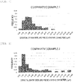
- Figs. 2 to 5 are the number-based particle size distributions of Examples 1 and 2 and Comparative Examples 1 and 2, respectively. The section of the crystal grain size in the particle size distribution was 1 ⁇ m, and the representative diameter of the crystal grain size corresponding to the median value of each section was shown on the horizontal axis.
- Example 1 As shown in Table 1, in Examples 1 and 2, the joining strength was significantly improved as compared with Comparative Examples 1 and 2. In addition, the joining strength was further improved in Example 1, in which the mode particle size is 2.50 ⁇ m or more and the standard deviation of hardness on the joint surface is 10.00 or less.
- the guide wire of the invention is high in joining strength. Also anticipated are torque transmission performance improvement and fatigue strength improvement resulting from stress concentration mitigation.
Landscapes
- Engineering & Computer Science (AREA)
- Mechanical Engineering (AREA)
- Health & Medical Sciences (AREA)
- Life Sciences & Earth Sciences (AREA)
- Chemical & Material Sciences (AREA)
- Animal Behavior & Ethology (AREA)
- Public Health (AREA)
- Biomedical Technology (AREA)
- Heart & Thoracic Surgery (AREA)
- Hematology (AREA)
- Pulmonology (AREA)
- General Health & Medical Sciences (AREA)
- Anesthesiology (AREA)
- Veterinary Medicine (AREA)
- Biophysics (AREA)
- Materials Engineering (AREA)
- Metallurgy (AREA)
- Organic Chemistry (AREA)
- Media Introduction/Drainage Providing Device (AREA)
- Pressure Welding/Diffusion-Bonding (AREA)
Abstract
Description
- The present invention relates to a guide wire.
- A guide wire is an elongated medical appliance that is inserted into a blood vessel so that a catheter or a stent for intravascular treatment is guided to a target position.
- The guide wire is required to travel through a complex curved or bifurcated portion of the blood vessel and pass through a stenosed site. Accordingly, the guide wire is required to be low in flexural rigidity for blood vessel selectivity and safety improvement on the side of intravascular insertion (distal side) and high in flexural rigidity in order to ensure pushing performance and torque transmission performance on the side where an operator performs operation (proximal side). Known in this regard is a guide wire in which one core wire is formed by joining wires made of metals having different thicknesses and material properties such that the distal and proximal sides thereof have different properties (e.g. PTL 1).
- PTL 1: International Publication No.
2013/100045 - In traveling through a blood vessel, the guide wire is curved in the shape of the blood vessel. An operator pushes, pulls, and rotates the guide wire when the guide wire passes through a stenosed site. Accordingly, the guide wire in which the metallic wires are joined needs to have a sufficient joining strength in the joint portion. On condition that the joining strength is insufficient, the guide wire has the risk of bending in the joint portion during intravascular use.
- The invention has been made to solve the above problem, and an object of the invention is to provide a guide wire with improved joining strength.
- The invention relates to a guide wire where a first wire and a second wire are solid-phase-joined to each other. The first wire and the second wire are made of a Ni-Ti-based alloy. When a section of a crystal grain size is 1 µm in a number-based particle size distribution of crystal grains of a metallographic structure of a joint surface between the first wire and the second wire, a frequency of a mode particle size is 25% or more and a frequency of a representative diameter being (mode particle size (µm) - 1 µm) or more and (mode particle size (µm) + 1 µm) or less is 60% or more.
- According to the invention, the joining strength of a joint portion is improved in the guide wire having the joint portion where the first wire and the second wire are joined. Accordingly, the guide wire is capable of reducing the risk of intravascular bending.
-
- [
Fig. 1] Fig. 1 is a partial vertical cross-sectional view illustrating a guide wire 10 (cross-sectional view along the major axis direction of the guide wire 10). - [
Fig. 2] Fig. 2 is a diagram illustrating the particle size distribution of Example 1. - [
Fig. 3] Fig. 3 is a diagram illustrating the particle size distribution of Example 2. - [
Fig. 4] Fig. 4 is a diagram illustrating the particle size distribution of Comparative Example 1. - [
Fig. 5] Fig. 5 is a diagram illustrating the particle size distribution of Comparative Example 2. - Hereinafter, embodiments of the invention will be described with reference to the accompanying drawings. It should be noted that the invention is not limited to the following embodiments. In the description of the drawings, the same elements are denoted by the same reference numerals with redundant description omitted. In addition, the dimensional ratios in the drawings are exaggerated for convenience of description and may differ from the actual ratios.
- In the description of the present specification, the direction in which a guide wire extends in a natural state (straight state without external force application) is "major axis direction". In a horizontal cross section of the guide wire with the major axis direction of the guide wire as a reference axis (axially orthogonal cross section), the direction toward or away from the guide wire is "radial direction". The direction of rotation with the major axis direction of the guide wire as a reference axis is "circumferential direction". In addition, the side of the guide wire inserted into a blood vessel is the distal side of the guide wire and the end portion side opposite to the distal side is the proximal side of the guide wire. In addition, "distal portion" is a part including a certain range in the major axis direction from the distal end (most distal end) and "proximal portion" is a part including a certain range in the major axis direction from the proximal end (most proximal end).
- In the present specification, "X to Y" indicating a range includes X and Y and means "X or more and Y or less".
-
Fig. 1 is a vertical cross-sectional view of aguide wire 10. - The
guide wire 10 is inserted into a blood vessel and used to guide a catheter to a target site in the blood vessel in a state of being inserted through the lumen of the therapeutic or diagnostic catheter (guide wire lumen). As illustrated inFig. 1 , theguide wire 10 according to a first embodiment includes an axially stretchingcore wire 20, acoil 30 and a distal coating layer (corresponding to a resin coating layer) 41 disposed in the distal portion of thecore wire 20, atubular member 50 disposed on the proximal side of thedistal coating layer 41, and aproximal coating layer 60 disposed in the proximal portion of thecore wire 20. - The length of the
guide wire 10 along the major axis direction is not particularly limited. The length may be, for example, 200 to 5000 mm. - As illustrated in
Fig. 1 , thecore wire 20 has afirst wire 21 disposed on the distal side in the major axis direction and asecond wire 22 disposed on the proximal side of thefirst wire 21. Thefirst wire 21 and thesecond wire 22 are joined in a solid phase via a joint surface d1 in ajoint portion 37. Thejoint portion 37 has a protrudingportion 70 protruding radially outward from the outer surface of thecore wire 20. - The
first wire 21 has adistal portion 36 disposed on the distal side of thefirst wire 21, a first constantouter diameter portion 34 disposed on the proximal side of thedistal portion 36, and a firsttapered portion 35 disposed between thedistal portion 36 and the first constantouter diameter portion 34. Thedistal portion 36 extends from the distal end of thefirst wire 21 to the distal end of the firsttapered portion 35 and has a substantially constant outer diameter along the major axis direction. The firsttapered portion 35 extends from the proximal end of thedistal portion 36 to the distal end of the first constantouter diameter portion 34 and has an outer diameter gradually increasing along the major axis direction. The first constantouter diameter portion 34 extends from the proximal end of the firsttapered portion 35 to the distal end of theprotruding portion 70 and has a substantially constant outer diameter along the major axis direction. The outer diameter of the first constantouter diameter portion 34 is 0.6 mm to 0.8 mm. - The
second wire 22 has a second constantouter diameter portion 38 disposed on the distal side of thesecond wire 22, a third constantouter diameter portion 40 disposed on the proximal side of the second constantouter diameter portion 38, and a secondtapered portion 39 disposed between the second constantouter diameter portion 38 and the third constantouter diameter portion 40. The second constantouter diameter portion 38 extends from the proximal end of theprotruding portion 70 to the distal end of the secondtapered portion 39 and has a substantially constant outer diameter along the major axis direction. The outer diameter of the second constantouter diameter portion 38 is substantially equal to the outer diameter of the first constantouter diameter portion 34 of thefirst wire 21 and is 0.6 mm to 0.8 mm. The secondtapered portion 39 extends from the proximal end of the second constantouter diameter portion 38 to the distal end of the third constantouter diameter portion 40 and has an outer diameter gradually increasing along the major axis direction. The third constantouter diameter portion 40 extends from the proximal end of the secondtapered portion 39 to the proximal end of thesecond wire 22 and has a substantially constant outer diameter along the major axis direction. - The
core wire 20 is formed by joining thefirst wire 21 and thesecond wire 22 in a solid phase. Each of thefirst wire 21 and thesecond wire 22 can be formed by grinding a metallic wire having a constant outer diameter. The outer diameter of thesecond wire 22 that is yet to be ground is larger than the outer diameter of thefirst wire 21 that is yet to be ground. By forming thecore wire 20 by grinding and then joining two wires different in outer diameter, the length that requires grinding is shorter than in a case where thecore wire 20 is formed by grinding one wire. Accordingly, by joining two wires different in outer diameter, it is possible to easily manufacture thecore wire 20 that has a low-flexural rigidity distal part and a high-flexural rigidity proximal part. In thecore wire 20, the outer diameter (mm) at the position at 150 mm from the joint surface d1 to the proximal side is, for example, 115% or more of the outer diameter (mm) at 150 mm from the joint surface d1 to the distal side. - Both the
first wire 21 and thesecond wire 22 have a substantially circular horizontal cross-sectional shape. It should be noted that the shapes of thefirst wire 21 and thesecond wire 22 are not limited thereto. For example, thefirst wire 21 and thesecond wire 22 may have other tapered or constant outer diameter portions between thedistal portion 36 and the first constantouter diameter portion 34 of thefirst wire 21 and between the second constantouter diameter portion 38 and the third constantouter diameter portion 40 of thesecond wire 22. In addition, the horizontal cross-sectional shape of thedistal portion 36 of the first wire may be rectangular. - Each of the
first wire 21 and thesecond wire 22 is made of a Ni-Ti-based alloy. The Ni-Ti-based alloy has superelasticity, and thus it is easy to restore the original shape after stress unloading even in the case of deformation to a plastic deformation region attributable to stress application. Suppressed as a result is theguide wire 10 being plastically deformed and bent during use to cause a decline in operability. In addition, on condition that thefirst wire 21 and thesecond wire 22 of thecore wire 20 are made of the same material, the change in physical properties from thefirst wire 21 to thesecond wire 22 including thejoint portion 37 is gradual, and thus it is easy to obtain the joining strength of thejoint portion 37. In addition, the physical properties of thefirst wire 21 and thesecond wire 22 are similar to each other, and thus the plastic deformation in the event of solid-phase joining is similar between thefirst wire 21 and thesecond wire 22 and the shape of thejoint portion 37 is substantially symmetrical with the joint surface as a plane of symmetry. As a result, when theguide wire 10 is subjected to a strong bending deformation, stress concentration on either thefirst wire 21 or thesecond wire 22 is mitigated, and thus the joining strength against the bending deformation is improved. - The Ni-Ti-based alloy is represented by, for example, the following Formula (1):
[Chem 1] NixTiyAa
- In the above Formula (1), A is an unavoidable impurity.
x, y, and a represent weight percent values. Satisfied in this case are 30 ≤ x ≤ 70, 30 ≤ y ≤ 70, 0 ≤ a ≤ 1, and x + y + a = 100. More preferably, 40 ≤ x ≤ 60, 40 ≤ y ≤ 60, 0 ≤ a ≤ 1, and x + y + a = 100 are satisfied in the Formula (1). - The
joint portion 37 is the part of thecore wire 20 that includes the joint surface d1 between thefirst wire 21 and thesecond wire 22 and the vicinity of the joint surface d1. Thejoint portion 37 is formed by performing solid-phase joining on the proximal surface of the wire forming thefirst wire 21 and the distal surface of the wire forming thesecond wire 22. - Solid-phase joining is a method for directly joining two metal materials. In solid-phase joining, a base metal is joined by plastic flow without melting. Solid-phase joining is performed at a temperature equal to or lower than a melting point, and a molten portion called a nugget is not formed on the joint surface. Accordingly, it is possible to suppress a significant difference between the material properties in the vicinity of the joint surface and the material properties of the base material. In other words, by performing solid-phase joining on the
first wire 21 and thesecond wire 22 of thecore wire 20, the change in material properties in the vicinity of thejoint portion 37 that is viewed along the major axis direction is small. Melt joining is another method for directly joining two metals. In melt joining, a plurality of base metals are joined by heat-melting and coagulating the base metals, and thus a nugget is formed on the joint surface. The nugget and the metal in the vicinity of the joint surface are degenerated from the base material by melting heat. Accordingly, the material properties in the vicinity of the joint surface may be significantly different from the material properties of the base material. Solid-phase joining and melt joining can be distinguished by checking the presence or absence of a nugget on the bimetallic joint surface with a scanning electron microscope. - How to join the
first wire 21 and thesecond wire 22 in a solid phase is not particularly limited. Examples of the method include friction joining, room-temperature pressure joining, high-temperature pressure joining, explosive joining, and electromagnetic pulse joining. Friction joining and high-temperature pressure joining are particularly preferable in joining small-outer diameter metallic wires such as thefirst wire 21 and thesecond wire 22. In these joining methods, the proximal surface of thefirst wire 21 and the distal surface of thesecond wire 22 are brought into pressure contact with each other in a state of abutting in the axial direction and heat is input to the portion where the two wires are in contact with each other. As a result, thefirst wire 21 and thesecond wire 22 are softened by the temperature of the vicinity of the contact portion rising. At the same time, thefirst wire 21 and thesecond wire 22 are compressed in the major axis direction and plastically deformed. The metal material in the vicinity of the contact portion between thefirst wire 21 and thesecond wire 22 is extruded radially outward as a result of the compression, and burrs corresponding in amount to the plastic deformation are formed on the joint surface d1. The heat input is stopped after the temperature of the contact portion is raised to an appropriate temperature, and then the temperature in the vicinity of the contact portion between thefirst wire 21 and thesecond wire 22 decreases and the solid-phase joining is achieved. Heat may be input to the contact portion between thefirst wire 21 and thesecond wire 22 by, for example, generating frictional heat by rotating either thefirst wire 21 or thesecond wire 22 such that the central axis serves as an axis of rotation. By an alternative method, the contact portion between thefirst wire 21 and thesecond wire 22 is energized to generate Joule heat. The amount of heat input can be controlled by adjusting joining conditions such as pressure, rotation speed, current, and how long to apply the conditions. In general, a sufficient heat input amount in the initial stage of joining is required for joining strength improvement. However, at an excessively large heat input amount, the contact portion between thefirst wire 21 and thesecond wire 22 may undergo a decline in strength or melt due to a thermal effect. At an excessively small heat input amount, the contact portion between thefirst wire 21 and thesecond wire 22 is insufficiently softened and the plastic deformation does not occur sufficiently, which results in a decline in joining strength. - It is preferable that the proximal portion of the
first wire 21 and the distal portion of thesecond wire 22 used in the joining process are given substantially the same outer diameter by processing such as grinding. With thefirst wire 21 and thesecond wire 22 abutting against each other, the positions of the two wires are unlikely to be misaligned on the joint surface dl, and thus the central axis of the core wire 20 (axis passing through substantially the center of the horizontal cross section of thecore wire 20 and extending in the major axis direction) is substantially straight. It should be noted that the central axis of thecore wire 20 substantially coincides with the central axis of theguide wire 10. - The proximal surface of the
first wire 21 used in the joining process is substantially perpendicular to the central axis of thefirst wire 21. The distal surface of thesecond wire 22 used in the joining process is substantially perpendicular to the central axis of thesecond wire 22. As a result, the proximal surface of thefirst wire 21 and the distal surface of thesecond wire 22 are formed with ease. It should be noted that each of the proximal surface of thefirst wire 21 and the distal surface of thesecond wire 22 used in the joining process may be inclined with respect to a plane perpendicular to the central axis of the wire and may be concave or convex. - Preferably, the proximal surface of the
first wire 21 and the distal surface of thesecond wire 22 are treated before the joining process for deposit and oxide film removal from each end surface. Examples of the treatment method include polishing and acid treatment. - As a result of the solid-phase joining, the
joint portion 37 is different in metallographic structure from the first constantouter diameter portion 34 of thefirst wire 21 and the second constantouter diameter portion 38 of thesecond wire 22 adjacent to thejoint portion 37. In general, the metallographic structure observed in thefirst wire 21 and thesecond wire 22 that are yet to be joined is a fibrous structure parallel to the major axis direction of each wire (elliptical structure having the major axis direction of each wire as a major axis). When thefirst wire 21 and thesecond wire 22 are joined in a solid phase, the metallographic structure in the vicinity of the joint surface d1 is fine grained by the heat and pressure applied during the joining and a thermally affected portion is observed therearound. Then, the fibrous metallographic structure changes or disappears in the direction along the direction of burr extrusion (outside in the radial direction) in the vicinity of the joint surface d1. In the present specification, when a vertical cross section including the central axis of thecore wire 20 is macroscopically observed with a scanning electron microscope (at a magnification of approximately 1000 times), the part where the direction of the fibrous metallographic structure changes from the direction parallel to the major axis direction of thefirst wire 21 or thesecond wire 22 is thejoint portion 37. The length of thejoint portion 37 along the major axis direction is equal to the length of the thermally affected portion along the major axis direction. - The joint surface d1 is where the proximal surface of the
first wire 21 and the distal surface of thesecond wire 22 are in contact with each other. In the present specification, in a case where the position where thefirst wire 21 and thesecond wire 22 are in contact with each other can be clearly identified in observing the metallographic structure of the vertical cross section of thecore wire 20 with a scanning electron microscope, that position is the joint surface d1. In a case where the fibrous metallographic structure disappears as a result of solid-phase joining and the joint surface d1 cannot be clearly identified, the middle position of thejoint portion 37 in the major axis direction of thecore wire 20 is the joint surface d1. - The joint surface d1 formed as a result of the solid-phase joining is substantially perpendicular to the central axis of the
core wire 20. In addition, it is preferable that the central axis of thefirst wire 21 and the central axis of thesecond wire 22 substantially coincide with each other on the joint surface d1 of theguide wire 10. It should be noted that the joint surface d1 may be inclined with respect to a plane perpendicular to the central axis of thecore wire 20 and may be concave or convex. - The metallographic structure of the joint surface d1 and its vicinity greatly affects the joining strength of the
first wire 21 and thesecond wire 22. In order to improve the joining strength of thefirst wire 21 and thesecond wire 22, it is preferable that the metallographic structure in the vicinity of the joint surface d1 is uniform. The size of the crystal grains of the metallographic structure correlates with metal hardness, and the hardness increases as the crystal grains decrease in size. Accordingly, on condition that the uniformity of the metallographic structure is low, local stress concentration attributable to a difference in hardness is likely to occur on the joint surface d1, which results in a decline in joining strength. In addition, as for thecore wire 20 joined in a solid phase, the height of burrs generated in thejoint portion 37 may be adjusted by mechanical polishing. At this time, thecore wire 20 that has a low metallographic structural uniformity in the vicinity of the joint surface d1 is non-uniform in terms of hardness distribution on the joint surface d1, and thus an unintended unevenness is likely to occur on the outer surface after mechanical polishing. Such unevenness on the outer surface causes local stress concentration, which leads to a decline in the joining strength of the joint surface d1. In particular, on the joint surface d1 between metallic wires small in outer diameter as in the case of theguide wire 10, the unevenness of the outer surface greatly affects the joining strength. - The uniformity of the metallographic structure can be evaluated by the particle size distribution of the crystal grains of the metallographic structure. The particle size distribution of the crystal grains of the metallographic structure is obtained by dividing the crystal grains in any area (measurement target region) into several sections between the maximum diameter and the minimum diameter and measuring the number and area of the crystal grains in each section. As for the particle size distribution in the vicinity of the joint surface d1 in the present specification, a vertical cross section including the intersection of the central axis of the
core wire 20 and the joint surface d1 is microscopically observed using a scanning electron microscope (at a magnification of approximately 5000 times) and the crystal grain size of the crystal grains in the measurement target region of the obtained image is expressed as a number-based frequency distribution. The area of each crystal grain is calculated from an image showing the grain boundary of the crystal grain using a crystal orientation-grain boundary microstructure automatic analysis device (OIM), and the crystal grain size is calculated as the diameter in a case where it is assumed that each crystal grain is a true sphere, that is, a two-dimensional plane and a perfect circle. The measurement target region of the particle size distribution is 0.075 mm × 0.075 mm with the intersection of the central axis of thecore wire 20 and the joint surface d1 at its center. The section of the crystal grain size in the particle size distribution is 1.00 µm. In addition, the crystal grain size that corresponds to the median value of each section is the representative diameter of the section. In other words, in the particle size distribution, the frequency of crystal grains with a representative diameter of 0.05 µm indicates the ratio of the number of crystal grains more than 0 µm and 1.00 µm or less in measured crystal grain size value to the total crystal grain count in the measurement target region. - The size of the crystal grains of the metallographic structure correlates with hardness. Accordingly, the uniformity of the metallographic structure can also be evaluated by hardness distribution. In order to enhance the joining strength, it is preferable that the hardness of the metal in the vicinity of the joint surface d1 is uniform. The hardness in the present specification is a value obtained by measuring the test force and pushing depth during indenter pushing and converting a pushing hardness obtained from a load unloading curve into a Vickers hardness conversion value. The hardness of the joint surface d1 is a five-point average value measured with respect to the vertical cross section including the intersection of the central axis of the
core wire 20 and the joint surface dl, and the five measurement points are the intersection and two at a position of 0.0625 mm and two at a position of 0.125 mm on the outer side in the radial direction along the joint surface d1 from the intersection. It should be noted that the hardness is obtained to two decimal places. - In order to improve the joining strength of the
first wire 21 and thesecond wire 22, it is preferable that thecore wire 20 entails little change in hardness along the major axis direction from the first constantouter diameter portion 34 of thefirst wire 21 to the second constantouter diameter portion 38 of thesecond wire 22. Accordingly, it is preferable that the metallographic structure in the vicinity of the joint surface d1 has an appropriately large crystal grain size. The metallographic structure in the vicinity of the joint surface d1 is recrystallized and fine grained by the heat and pressure during the solid-phase joining. At the same time, the hardness of thejoint portion 37 positioned around the joint surface d1 is thermally affected to become lower than the hardness of thefirst wire 21 and thesecond wire 22 that are yet to be joined in a solid phase. Accordingly, on condition that the ratio of the fine crystal grains contained in the joint surface d1 is high, the change in the hardness of thejoint portion 37 in the vicinity of the joint surface d1 is large and local stress concentration is likely to occur on the joint surface d1 and at the boundary point of hardness change. As a result, a large change in hardness along the major axis direction occurs from the first constantouter diameter portion 34 of thefirst wire 21 to the second constantouter diameter portion 38 of thesecond wire 22 of thecore wire 20 and it becomes difficult to improve the joining strength in a tensile test. - In the number-based particle size distribution of the crystal grains of the metallographic structure of the joint surface dl, the frequency of the mode particle size at a crystal grain size section of 1 µm is 25% or more and more preferably 28% or more. The mode particle size is the representative diameter of the section that has the highest frequency in the particle size distribution (mode diameter). By containing 25% or more of crystal grains with the mode particle size, the joint surface d1 has a high metallographic structural uniformity. As a result, the joint surface d1 is unlikely to undergo local stress concentration attributable to a difference in physical properties and the joining strength is improved. In addition, although the upper limit of the frequency of the mode particle size is 100% or less in the number-based particle size distribution of the crystal grains of the metallographic structure of the joint surface d1, the upper limit is usually 40% or less.
- When the section of the crystal grain size is 1 µm in the number-based particle size distribution of the crystal grains of the metallographic structure of the joint surface d1, the frequency of the representative diameter being (mode particle size (µm) - 1 µm) or more and (mode particle size (µm) + 1 µm) or less is preferably 60% or more and more preferably 62% or more. In other words, the total frequency of the frequency of the section having the mode particle size and the frequency of the two sections adjacent to the section having the mode particle size is preferably 60% or more and more preferably 62% or more. The joint surface d1 having such a particle size distribution has a higher metallographic structural uniformity. Accordingly, the joint surface d1 is even less likely to undergo local stress concentration attributable to a difference in physical properties and the effect of joining strength improvement further increases. In addition, although the upper limit of the frequency of the mode particle size is 100% or less in the number-based particle size distribution of the crystal grains of the metallographic structure in the vicinity of the joint surface dl, the upper limit is usually 75% or less.
- In the number-based particle size distribution of the crystal grains of the metallographic structure of the joint surface dl, the mode particle size is preferably 2.50 µm or more when the section of the crystal grain size is 1 µm. By reducing the ratio of fine crystal grains contained in the joint surface dl, the
joint portion 37 is capable of reducing the change in hardness in the vicinity of the joint surface d1. As a result, in thecore wire 20, the change in hardness along the major axis direction is small from the first constantouter diameter portion 34 of thefirst wire 21 to the second constantouter diameter portion 38 of thesecond wire 22 and the joining strength is further improved in a tensile test. The upper limit of the mode particle size is preferably 5.50 µm or less and more preferably 3.50 µm or less. The hardness of the joint surface d1 does not significantly decrease by reducing the ratio of coarse crystal grains contained in the joint surface d1, and thus the joint surface d1 is capable of obtaining a high joining strength. - The standard deviation of hardness at the joint surface d1 is preferably 10.00 or less and more preferably 9.00 or less. It should be noted that the standard deviation of hardness is an unbiased standard deviation using five points measured at the joint surface d1 as samples and is obtained to two decimal places. By the standard deviation of hardness being 10.00 or less, the joint surface d1 has a high metallographic structural uniformity. As a result, the joint surface d1 is unlikely to undergo local stress concentration attributable to a difference in physical properties and the joining strength is improved. In addition, the joint surface d1 is improved in terms of mechanical polishing workability. Although the lower limit of the standard deviation of hardness at the joint surface d1 is 0, the lower limit is usually 4.00 or more.
- The metallographic structure of the joint surface d1 as described above can be obtained by appropriately controlling the amounts of heat input, heat radiation, and deformation in the contact portion between the
first wire 21 and thesecond wire 22 in performing solid-phase joining. The amount of heat input and the amount of heat radiation affect the degrees of recrystallization and growth of the crystal grains in the vicinity of the joint surface d1. The amount of deformation during plastic deformation affects the degree to which the fine crystal grains resulting from the solid-phase joining remain in the vicinity of the joint surface d1. The amounts of heat input, heat radiation, and deformation can be controlled by adjusting various solid-phase joining conditions. - In a case where Joule heat is used for heat input to the contact portion between the
first wire 21 and thesecond wire 22 in the solid-phase joining, the amounts of heat input, heat radiation, and deformation can be controlled by a current value and energization time because the Joule heat is a function of resistance, a current value, and energization time. In particular, in order to obtain a metallographic structure in which the joining strength of the joint surface d1 is high in solid-phase joining between metallic wires small in outer diameter as in the case of thefirst wire 21 and thesecond wire 22, it is important to control the current value for a certain time from energization initiation to deformation initiation. When energization is started, Joule heat is generated in the contact portion due to the high contact resistance attributable to the fine unevenness on the proximal surface of thefirst wire 21 and the distal surface of thesecond wire 22. When thefirst wire 21 and thesecond wire 22 start to be deformed by the generated Joule heat, the fine unevenness is crushed, the area of contact between thefirst wire 21 and thesecond wire 22 increases, and the contact resistance decreases. Accordingly, the amount of Joule heat generation decreases. Deformation occurs at the same time, and thus the area of contact between a joining device and thefirst wire 21 or thesecond wire 22 increases. Accordingly, the amount of heat radiation from the contact portion increases. In a case where a high current is applied in a short time in the initial stage of joining, the amount of heat input rapidly increases immediately after energization initiation, and yet the amount rapidly decreases subsequently because the deformation proceeds at a high speed. At the same time, a rapid increase in heat radiation amount attributable to the deformation also occurs. As a result, the temperature rise in the contact portion stops in a short time, and thus the amount of deformation decreases. In a case where a low current is applied for a long time, the amount of heat input attributable to energization is small, and thus the amount of deformation is small. In this manner, the current value for a certain time from energization initiation to deformation initiation affects both the amount of heat input and the amount of heat radiation and affects the amount of deformation as a result. From the transition of the amount of deformation, it could be estimated that it takes 5 ms to reach the maximum temperature from energization initiation. Although the specific current value is appropriately set in view of, for example, the outer diameters and compositions of the first wire and the second wire, the current value at 5 ms from energization initiation is preferably 10 A to 1000 A and preferably more than 75 A and less than 300 A. As a result, thecore wire 20 is capable of obtaining a metallographic structure in which the joining strength of the joint surface d1 between thefirst wire 21 and thesecond wire 22 is high. - In a case where Joule heat is used as a method for heat input to the contact portion between the
first wire 21 and thesecond wire 22, the pressure during pressure contact between the proximal surface of thefirst wire 21 and the distal surface of thesecond wire 22 is, for example, 50 MPa to 1000 MPa. If necessary, the pressure may be increased or decreased in the joining process. - In obtaining the metallographic structure of the joint surface d1 as described above, the amount of deformation is preferably 0.80 mm or more and more preferably 1.00 mm or more. The upper limit of the amount of deformation is not particularly limited, and examples of the upper limit include 1.50 mm or less. It should be noted that the amount of deformation is the amount of displacement of the lengths of the
first wire 21 and thesecond wire 22 in the major axis direction before and after solid-phase joining. At a small deformation amount, the joint surface d1 is likely to undergo a local increase in hardness as the remarkably fine crystal grains resulting from the solid-phase joining remain on the joint surface d1. On condition that the amount of heat is increased for an increase in deformation amount, thejoint portion 37 is likely to be thermally affected to undergo a decline in hardness. - In the form of
Fig. 1 , thecore wire 20 has the protrudingportion 70 formed by mechanically polishing burrs on the joint surface d1 in thejoint portion 37. The protrudingportion 70 protrudes radially outward from the outer surface of thecore wire 20. In other words, the outer diameter of the protrudingportion 70 is larger than the outer diameter of the first constantouter diameter portion 34 of thefirst wire 21 disposed in the vicinity of thejoint portion 37 and the outer diameter of the second constantouter diameter portion 38 of thesecond wire 22 disposed in the vicinity of thejoint portion 37. The protrudingportion 70 is formed in thejoint portion 37 between thefirst wire 21 and thesecond wire 22, and thus the area of the joint surface d1 is large and the joining strength is improved. In addition, by the outer diameter of the protrudingportion 70 being large, it is possible to prevent theguide wire 10 from locally bending in thejoint portion 37 in the event of simultaneous force application from both the distal portion and the proximal portion. The flexural rigidity of theguide wire 10 can be expressed by Young's modulus and the moment of inertia of area. As a result of solid-phase joining, thejoint portion 37 is lower in hardness than the first constant outer diameter portion of thefirst wire 21 disposed in the vicinity of thejoint portion 37 and the second constant outer diameter portion of thesecond wire 22 disposed in the vicinity of thejoint portion 37. Assuming that the hardness and Young's modulus are in a direct proportional relationship, the flexural rigidity of theguide wire 10 decreases in thejoint portion 37 in a case where thejoint portion 37 is substantially equal in outer diameter to the first constantouter diameter portion 34 and the second constantouter diameter portion 38 of thesecond wire 22. Accordingly, only thejoint portion 37 is easily deformed when theguide wire 10 receives a compressive force in the major axis direction. By providing the protrudingportion 70, thejoint portion 37 is larger in outer diameter and the moment of inertia of area than the first constantouter diameter portion 34 and the second constantouter diameter portion 38 of thesecond wire 22. As a result, with theguide wire 10 having the protrudingportion 70, it is possible to suppress a decline in flexural rigidity in thejoint portion 37 and prevent thejoint portion 37 from being deformed alone. As a result, with theguide wire 10, the torque and the pushing force that an operator applies to the proximal portion of thesecond wire 22 can be efficiently transmitted to thefirst wire 21. - The outer shape of the protruding
portion 70 is substantially trapezoidal in the vertical cross-sectional view of theguide wire 10. In addition, the joint surface d1 between thefirst wire 21 and thesecond wire 22 is positioned substantially at the center of the upper base of the trapezoid. In other words, the joint surface d1 between thefirst wire 21 and thesecond wire 22 is positioned in the maximum outer diameter portion of the protrudingportion 70. It should be noted that the outer shape of the protrudingportion 70 in the vertical cross-sectional view of theguide wire 10 is not limited to the trapezoidal shape and the shape may be a circular arc shape or a polygonal shape. In addition, the upper base of the trapezoidal shape of the protrudingportion 70 observed in the vertical cross-sectional view of theguide wire 10 is not limited to a straight line and may be a curve. - The height of the protruding
portion 70 is the distance between the maximum outer diameter portion of the protruding portion and the outer surface of the first constantouter diameter portion 34 of thefirst wire 21 or the second constantouter diameter portion 38 of thesecond wire 22. In a case where the outer shape of the protrudingportion 70 in the vertical cross-sectional view of theguide wire 10 is trapezoidal, the height of the protrudingportion 70 is the distance between the upper base of the trapezoid and the outer surface of thefirst wire 21 or thesecond wire 22 parallel to the upper base of the trapezoid and is preferably 0.001 mm to 0.200 mm and more preferably 0.020 mm to 0.100 mm. - The maximum outer diameter (mm) of the
first wire 21 excluding the protrudingportion 70 is 90% to 100% of the maximum outer diameter (mm) of the protrudingportion 70, and the maximum outer diameter (mm) of thesecond wire 22 excluding the protrudingportion 70 is 100% to 120% of the maximum outer diameter (mm) of the protrudingportion 70. - The
coil 30 is disposed so as to cover a certain range of the distal portion of thefirst wire 21. Thecoil 30 is formed by spirally winding a wire around thefirst wire 21 and along the circumferential direction of thefirst wire 21. It is preferable that thecoil 30 and the outer surface of thefirst wire 21 are in close contact with each other. In addition, it is preferable that thecoil 30 is formed so as to have a gap between adjacent windings in a state where no external force is applied. It should be noted that thecoil 30 may be formed so as to have no gap between adjacent windings in a state where no external force is applied. - It is preferable that the wire forming the
coil 30 is formed of a radiopaque material. Examples of the radiopaque material include metal materials such as precious metals (e.g. gold, platinum, and tungsten) and alloys containing the metals. - The distal end of the
coil 30 is fixed to the distal portion of thefirst wire 21 by a fixingmember 31. The proximal end of thecoil 30 is fixed to the first taperedportion 35 of thefirst wire 21 by a fixingmember 32. Examples of the material that forms the fixing member include an adhesive, a brazing material, and solder. - The
distal coating layer 41 is made of a resin material and is formed so as to cover the distal portion of thecore wire 20 including thecoil 30. The distal portion of thedistal coating layer 41 preferably has a rounded shape so as not to damage a blood vessel wall. In addition, the proximal portion of thedistal coating layer 41 is positioned in the first constantouter diameter portion 34 of the core wire 20 (first wire 21). - The
distal coating layer 41 is preferably formed of a highly flexible resin material. As a result, the distal side of theguide wire 10 is flexible and damage to an intravascular wall can be prevented. Examples of the resin material that forms thedistal coating layer 41 include polyolefin (e.g. polyethylene and polypropylene), polyvinyl chloride, polyester (e.g. PET and PBT), polyamide, polyimide, polystyrene, polycarbonate, silicone resin, fluorine-based resin (e.g. PTFE, ETFE, and PFA), urethane-based resin, composite materials thereof, various rubber materials (e.g. latex rubber and silicone rubber), and composite materials in which two or more of these are combined. Of the above materials, it is more preferable to use the urethane-based resin. - The thickness of the
distal coating layer 41 is not particularly limited and is preferably, for example, 5 µm to 500 µm. It should be noted that thedistal coating layer 41 is not limited to a one-layer structure and may be configured by laminating a plurality of layers. - The
distal coating layer 41 is preferably covered with a hydrophilic coating layer (not illustrated). As a result, theguide wire 10 is improved in terms of operability as a result of frictional resistance reduction in relation to the wall of the blood vessel into which theguide wire 10 is inserted and the inner wall of the catheter. - The material that forms the hydrophilic coating layer is not particularly limited, and examples thereof include known hydrophilic substances consisting of, for example, cellulose-based polymer substance, polyethylene oxide-based polymer substance, maleic anhydride-based polymer substance (e.g. maleic anhydride copolymer such as methyl vinyl ether-maleic anhydride copolymer), acrylamide-based polymer substance (e.g. block copolymer of polyacrylamide and polyglycidylmethacrylate-dimethylacrylamide (PGMA-DMAA)), water-soluble nylon, polyvinyl alcohol, and polyvinylpyrrolidone.
- The thickness of the hydrophilic coating layer is not particularly limited and is preferably, for example, 0.1 µm to 100 µm.
- The
tubular member 50 is disposed in the first constantouter diameter portion 34 of thefirst wire 21. The distal portion of the tubular member is in contact with the proximal portion of thedistal coating layer 41, and the proximal end of thedistal coating layer 41 is in the lumen of thetubular member 50. The proximal portion of thetubular member 50 is fixed to thefirst wire 21 by a fixingmember 51. The proximal portion of thetubular member 50 has a taperedportion 52, which has an outer diameter gradually decreasing toward the proximal side. The fixingmember 51, which is positioned closer to the proximal side than the proximal end of thetubular member 50, is formed in a tapered shape so as to be continuous with the taperedportion 52 of thetubular member 50. - The
tubular member 50 is preferably made of metal. Examples of the metal that forms thetubular member 50 include stainless steel, a superelastic alloy, a cobalt-based alloy, precious metals (e.g. gold, platinum, and tungsten), and alloys containing the metals (platinum-iridium alloy). - As illustrated in
Fig. 1 , theproximal coating layer 60 is formed so as to cover at least a part of the outer surface of thesecond wire 22. Theproximal coating layer 60 has aninner layer 61 covering the outer surface of thesecond wire 22, anouter layer 62 covering the outer surface of the inner layer, and alinear body 63 spirally wound around the outer surface of theouter layer 62. - Examples of the material that forms the
inner layer 61 and theouter layer 62 include a fluorine-based resin (e.g. polytetrafluoroethylene (PTFE) and tetrafluoroethylene-ethylene copolymer (ETFE)). In addition, theinner layer 61 and theouter layer 62 may contain a pigment. - It should be noted that the
proximal coating layer 60 is not limited to the configuration described above and may be configured by, for example, one layer. - The
linear body 63 is a member that is spirally wound along the circumferential direction of thesecond wire 22 and has a convex shape from the outer surface of theouter layer 62 toward the outside in the radial direction. Thelinear body 63 is formed such that adjacent windings are separated from each other. With thelinear body 63, the outer surface of thesecond wire 22 has a plurality of convex portions and concave portions formed between the adjacent convex portions. - The
linear body 63 is preferably formed of resin. A fluorine-based resin (e.g. polytetrafluoroethylene (PTFE) and tetrafluoroethylene-hexafluoropropylene copolymer (FEP)) can be used as the resin that forms thelinear body 63. In addition, thelinear body 63 may contain a pigment. - The
linear body 63 is spirally wound around the outer surface of theouter layer 62 by dipping or spotting. As for the dipping method, with a masking tape spirally wound around the part on theouter layer 62 where a concave portion is to be formed, thesecond wire 22 is immersed in a solution containing the resin forming thelinear body 63 and dried, and then the masking tape is removed. As for the spotting method, the resin forming thelinear body 63 that is dissolved in a solvent or is in a molten state is linearly extruded onto the outer surface of theouter layer 62 of thesecond wire 22 that moves in the major axis direction while rotating. Thelinear body 63 may be fixed to the outer surface of theouter layer 62 by being wound around the outer surface of theouter layer 62 and then heated to a temperature close to the melting point temperature of thelinear body 63. By these methods, the resin is spirally applied to the outer surface of theouter layer 62 of thesecond wire 22 and thelinear body 63 as a convex portion directed radially outward from the outer surface of theouter layer 62 is formed. In a vertical cross-sectional view of thesecond wire 22, each convex portion has a top portion as the position of the convex portion that protrudes the most to the outside in the radial direction, a distal end portion positioned closer to the distal side than the top portion, and a proximal end portion positioned closer to the proximal side than the top portion. The contour of the outer surface of the convex portion is a smooth circular arc shape connecting the distal end portion, the top portion, and the proximal end portion. It should be noted that the contour of the outer surface of the convex portion in the vertical cross-sectional view of thesecond wire 22 is not limited to the circular arc and may be an elliptical arc, a triangle, or a rectangle. - The height of the convex portion is preferably 0.001 mm to 0.100 mm. It should be noted that the height of the convex portion is the length of a perpendicular line drawn from the top portion of the convex portion to the outer surface of the
outer layer 62 in the vertical cross-sectional view of thesecond wire 22. - The effects of the invention will be described with reference to the following examples and comparative examples. Unless otherwise specified, each operation was performed at room temperature (15 to 29°C).
- Two Ni-Ti alloy wires (outer diameter: 0.68 to 0.72 mm) were prepared, and the end portions of the wires were solid-phase-joined to each other. As for the composition of the Ni-Ti alloy, Ni was 55 to 56% by weight and the rest was Ti. The two wires were disposed in a joining device in an axially aligned state, and each wire was clamped and fixed. Next, the end surfaces of the two wires were brought into pressure contact with each other and the joining device was energized. The two wires were solid-phase-joined by being softened and plastically deformed by the heat generated in the contact portion between the two wires. As for the joined wires, burrs protruding outward in the radial direction of the wire were formed at the contact position of the two wires as a result of the plastic deformation attributable to compression. The burrs were mechanically polished to obtain a wire with a protruding portion having an outer diameter of 0.62 mm to 0.72 mm. The outer diameter was measured using a thickness gauge. The obtained wire was used as a test piece for the following evaluation. In Example 1, the current value at 5 ms from energization initiation was 200 A.
- In this example and the comparative examples, the current value at 5 ms from energization initiation was 75 to 300 A.
- Two Ni-Ti alloy wires (outer diameter: 0.68 to 0.72 mm) were prepared, and the end portions of the wires were solid-phase-joined to each other. As for the composition of the Ni-Ti alloy, Ni was 55 to 56% by weight and the rest was Ti. The two wires were disposed in a joining device in an axially aligned state, and each wire was clamped and fixed. Next, the end surfaces of the two wires were brought into pressure contact with each other and the joining device was energized. The two wires were solid-phase-joined by being softened and plastically deformed by the heat generated in the contact portion between the two wires. As for the joined wires, burrs protruding outward in the radial direction of the wire were formed at the contact position of the two wires as a result of the plastic deformation attributable to compression. The burrs were mechanically polished to obtain a wire with a protruding portion having an outer diameter of 0.62 mm to 0.72 mm. The outer diameter was measured using a thickness gauge. The obtained wire was used as a test piece for the following evaluation. In Example 2, the current value at 5 ms from energization initiation was 100 A.
- Two Ni-Ti alloy wires (outer diameter: 0.68 to 0.72 mm) were prepared, and the end portions of the wires were solid-phase-joined to each other. As for the composition of the Ni-Ti alloy, Ni was 55 to 56% by weight and the rest was Ti. The two wires were disposed in a joining device in an axially aligned state, and each wire was clamped and fixed. Next, the end surfaces of the two wires were brought into pressure contact with each other and the joining device was energized. The two wires were solid-phase-joined by being softened and plastically deformed by the heat generated in the contact portion between the two wires. As for the joined wires, burrs protruding outward in the radial direction of the wire were formed at the contact position of the two wires as a result of the plastic deformation attributable to compression. The burrs were mechanically polished to obtain a wire with a protruding portion having an outer diameter of 0.62 mm to 0.72 mm. The outer diameter was measured using a thickness gauge. The obtained wire was used as a test piece for the following evaluation. In Comparative Example 1, the current value at 5 ms from energization initiation was 300 A.
- Two Ni-Ti alloy wires (outer diameter: 0.68 to 0.72 mm) were prepared, and the end portions of the wires were solid-phase-joined to each other. As for the composition of the Ni-Ti alloy, Ni was 55 to 56% by weight and the rest was Ti. The two wires were disposed in a joining device in an axially aligned state, and each wire was clamped and fixed. Next, the end surfaces of the two wires were brought into pressure contact with each other and the joining device was energized. The two wires were solid-phase-joined by being softened and plastically deformed by the heat generated in the contact portion between the two wires. As for the joined wires, burrs protruding outward in the radial direction of the wire were formed at the contact position of the two wires as a result of the plastic deformation attributable to compression. The burrs were mechanically polished to obtain a wire with a protruding portion having an outer diameter of 0.62 mm to 0.72 mm. The outer diameter was measured using a thickness gauge. The obtained wire was used as a test piece for the following evaluation. In Comparative Example 2, the current value at 5 ms from energization initiation was 75 A.
- Before and after the solid-phase joining, the major-axis-direction distance between the two clamps fixing the wire was recorded. The difference in inter-clamp distance before and after the solid-phase joining was regarded as the amount of deformation.
- The joining strength of the test piece including the joint portion was obtained in a tensile test using an autograph (manufactured by Shimadzu Corporation). The test piece was fixed to chucks above and below such that the joint portion was positioned in the middle between the chucks. The upper portion of the test piece was pulled, and the maximum test force until the breaking of the test piece was regarded as the joining strength of the test piece. The distance between the chucks (original reference point distance) was 8 mm, and the test speed was 5 mm/min.
- The hardness of the test piece was obtained in a micro pushing test in accordance with International Standard ISO14577-1. After performing resin embedding on the joint surface of the test piece and the part including the vicinity thereof, cutting and polishing were performed to expose a vertical cross section including the central axis of the test piece or the vicinity of the central axis. Using a dynamic ultra-micro hardness tester (DUH-211S, manufactured by Shimadzu Corporation) and in accordance with ISO14577-1 (instrumentation pushing hardness test), the displacement-test force at a time when an indenter was pushed into a predetermined position in the vertical cross section until the test force became 65 µN and the indenter was pulled up after five-second holding was recorded and the pushing hardness (N/mm2) obtained from a load unloading curve was multiplied by 0.0924 to calculate a value converted into a Vickers hardness conversion value (HV*). It should be noted that a triangular pan indenter (inter-ridge angle: 115 degrees, Berkovich-type) was used for the measurement. As for the hardness at the joint surface, a five-point average value and an unbiased standard deviation were obtained to two decimal places with respect to the vertical cross section including the intersection of the central axis of the test piece and the joint surface and the five measurement points were the intersection and two at a position of 0.0625 mm and two at a position of 0.125 mm on the outer side in the radial direction along the joint surface d1 from the intersection.
- After performing resin embedding on the test piece, cutting and polishing were performed to expose a vertical cross section including the central axis of the test piece or the vicinity of the central axis. In the vertical cross section of the test piece, the 0.075 mm × 0.075 mm measurement target region with the intersection of the central axis of the test piece and the joint surface at its center was observed at a magnification of 5000 times using a scanning electron microscope and an image showing the grain boundaries of the crystal grains was obtained using a crystal orientation-grain boundary microstructure automatic analysis device (OIM). The area of the crystal grains in the measurement target region was calculated, and crystal grain size calculation was performed on the assumption that each crystal grain was a true sphere. It should be noted that the crystal grains across the boundary of the measurement target region were included in the calculation. Based on the obtained crystal grain size, a number-based particle size distribution was created at a crystal grain size section of 1 µm.
- Table 1 shows the amount of deformation, the joining strength, the mode particle size, the frequency of crystal grains having the mode particle size, the frequency of crystal grains having a crystal grain size with a representative diameter of (mode particle size (µm) - 1 µm) or more and (mode particle size (µm) + 1 µm) or less, the hardness, and the standard deviation of hardness regarding each of Examples 1 and 2 and Comparative Examples 1 and 2.
Figs. 2 to 5 are the number-based particle size distributions of Examples 1 and 2 and Comparative Examples 1 and 2, respectively. The section of the crystal grain size in the particle size distribution was 1 µm, and the representative diameter of the crystal grain size corresponding to the median value of each section was shown on the horizontal axis.[Table 1] Example 1 Example 2 Comparative Example 1 Comparative Example 2 Deformation amount (mm) (average value of n = 15) 1.34 1.09 1.09 0.98 Joining strength (N) (average value of n = 10) 375 319 280 284 Mode particle size (µm) 2.5 1.5 2.5 1.5 Frequency (%) of crystal grains having mode particle size 28.9 28.4 23.7 33.1 Frequency (%) of crystal grains having crystal grain size of (mode particle size (um) - 1 µm) or more and (mode particle size (µm) + 1 µm) or less 68.7 62.3 64.2 59.4 Hardness 256.06 287.65 278.39 224.19 Standard deviation of hardness 8.24 14.12 14.70 18.18 - As shown in Table 1, in Examples 1 and 2, the joining strength was significantly improved as compared with Comparative Examples 1 and 2. In addition, the joining strength was further improved in Example 1, in which the mode particle size is 2.50 µm or more and the standard deviation of hardness on the joint surface is 10.00 or less.
- As described above, the guide wire of the invention is high in joining strength. Also anticipated are torque transmission performance improvement and fatigue strength improvement resulting from stress concentration mitigation.
- This application is based on
Japanese Patent Application No. 2020-061404 filed on March 30, 2020 -
- 10
- Guide wire
- 20
- Core wire
- 21
- First wire
- 22
- Second wire
- 30
- Coil
- 31, 32, 51
- Fixing member
- 34
- First constant outer diameter portion
- 35
- First tapered portion
- 36
- Distal portion
- 37
- Joint portion
- 38
- Second constant outer diameter portion
- 39
- Second tapered portion
- 40
- Third constant outer diameter portion
- 41
- Distal coating layer
- 50
- Tubular member
- 52
- Tapered portion
- 60
- Proximal coating layer
- 61
- Inner layer
- 62
- Outer layer
- 63
- Linear body
- 70
- Protruding portion
Claims (3)
- A guide wire where a first wire and a second wire are solid-phase-joined to each other, whereinthe first wire and the second wire are made of a Ni-Ti-based alloy, andwhen a section of a crystal grain size is 1 µm in a number-based particle size distribution of crystal grains of a metallographic structure of a joint surface between the first wire and the second wire, a frequency of a mode particle size is 25% or more and a frequency of a representative diameter being (mode particle size (µm) - 1 µm) or more and (mode particle size (µm) + 1 µm) or less is 60% or more.
- The guide wire according to claim 1, wherein the mode particle size is 2.50 µm or more.
- The guide wire according to claim 1 or 2, wherein a standard deviation of hardness at the joint surface is 10.00 or less.
Applications Claiming Priority (2)
| Application Number | Priority Date | Filing Date | Title |
|---|---|---|---|
| JP2020061404 | 2020-03-30 | ||
| PCT/JP2021/007653 WO2021199831A1 (en) | 2020-03-30 | 2021-03-01 | Guide wire |
Publications (2)
| Publication Number | Publication Date |
|---|---|
| EP4112219A1 true EP4112219A1 (en) | 2023-01-04 |
| EP4112219A4 EP4112219A4 (en) | 2023-03-08 |
Family
ID=77927070
Family Applications (1)
| Application Number | Title | Priority Date | Filing Date |
|---|---|---|---|
| EP21781029.0A Pending EP4112219A4 (en) | 2020-03-30 | 2021-03-01 | GUIDE CABLE |
Country Status (5)
| Country | Link |
|---|---|
| US (1) | US12485252B2 (en) |
| EP (1) | EP4112219A4 (en) |
| JP (1) | JP7557528B2 (en) |
| CN (1) | CN115348879B (en) |
| WO (1) | WO2021199831A1 (en) |
Families Citing this family (1)
| Publication number | Priority date | Publication date | Assignee | Title |
|---|---|---|---|---|
| WO2025099886A1 (en) * | 2023-11-09 | 2025-05-15 | 朝日インテック株式会社 | Medical device |
Family Cites Families (15)
| Publication number | Priority date | Publication date | Assignee | Title |
|---|---|---|---|---|
| JP4203358B2 (en) * | 2002-08-08 | 2008-12-24 | テルモ株式会社 | Guide wire |
| CN100558423C (en) * | 2003-12-18 | 2009-11-11 | 泰尔茂株式会社 | guide line |
| EP1712251B1 (en) | 2005-04-15 | 2010-05-05 | Terumo Kabushiki Kaisha | Guide Wire |
| JP4734015B2 (en) * | 2005-04-15 | 2011-07-27 | テルモ株式会社 | Guide wire manufacturing method |
| JP4734029B2 (en) * | 2005-05-23 | 2011-07-27 | テルモ株式会社 | Guide wire manufacturing method |
| JP5020630B2 (en) * | 2006-12-28 | 2012-09-05 | テルモ株式会社 | Guide wire |
| WO2008139829A1 (en) * | 2007-05-09 | 2008-11-20 | Japan Science And Technology Agency | Guide wire and stent |
| JP5472915B2 (en) | 2010-05-24 | 2014-04-16 | 株式会社オーク製作所 | Discharge lamp |
| WO2013100045A1 (en) | 2011-12-28 | 2013-07-04 | テルモ株式会社 | Guide wire |
| JP5985849B2 (en) * | 2012-03-23 | 2016-09-06 | 株式会社豊田中央研究所 | JOINT BODY, MANUFACTURING METHOD THEREOF, AND MEMBER |
| US9636485B2 (en) * | 2013-01-17 | 2017-05-02 | Abbott Cardiovascular Systems, Inc. | Methods for counteracting rebounding effects during solid state resistance welding of dissimilar materials |
| JP6109329B2 (en) | 2014-03-14 | 2017-04-05 | 古河電気工業株式会社 | Cu-Al-Mn alloy material, method for producing the same, and bar or plate material using the same |
| WO2016149193A1 (en) * | 2015-03-13 | 2016-09-22 | Lake Region Manufacturing Inc. D/B/A Lake Region Medical | Solid state methods for joining dissimilar metal guidewire segments without the use of tertiary material |
| JP2017113267A (en) * | 2015-12-24 | 2017-06-29 | 住友電気工業株式会社 | Medical guide wire |
| JP7179568B2 (en) | 2018-10-05 | 2022-11-29 | 株式会社Screenホールディングス | Substrate processing method and substrate processing apparatus |
-
2021
- 2021-03-01 EP EP21781029.0A patent/EP4112219A4/en active Pending
- 2021-03-01 WO PCT/JP2021/007653 patent/WO2021199831A1/en not_active Ceased
- 2021-03-01 CN CN202180026078.9A patent/CN115348879B/en active Active
- 2021-03-01 JP JP2022511673A patent/JP7557528B2/en active Active
-
2022
- 2022-06-08 US US17/835,477 patent/US12485252B2/en active Active
Also Published As
| Publication number | Publication date |
|---|---|
| EP4112219A4 (en) | 2023-03-08 |
| CN115348879A (en) | 2022-11-15 |
| US12485252B2 (en) | 2025-12-02 |
| WO2021199831A1 (en) | 2021-10-07 |
| US20220296861A1 (en) | 2022-09-22 |
| JP7557528B2 (en) | 2024-09-27 |
| CN115348879B (en) | 2023-06-02 |
| JPWO2021199831A1 (en) | 2021-10-07 |
Similar Documents
| Publication | Publication Date | Title |
|---|---|---|
| CN100558423C (en) | guide line | |
| JP5295104B2 (en) | Guidewire and stent | |
| US8192373B2 (en) | Medical guide wire and process for production thereof | |
| EP4249030A1 (en) | Medical catheter and preparation method therefor | |
| US20220176083A1 (en) | Guide wire and method for manufacturing guide wire | |
| US12485252B2 (en) | Guide wire | |
| JP5628515B2 (en) | Guide wire | |
| JP2023169196A (en) | Medical devices for magnetic resonance imaging and related methods | |
| JP2017113267A (en) | Medical guide wire | |
| CN101537222A (en) | Guide wire | |
| JP4136370B2 (en) | Method for producing core material for medical guide wire and medical guide wire | |
| US20240024639A1 (en) | Guide wire and method for producing guide wire | |
| US20250262416A1 (en) | Guide wire and method for producing guide wire | |
| JPH048065B2 (en) | ||
| WO2022044436A1 (en) | Guide wire | |
| JP2017100164A (en) | Manufacturing method of very small thin wall substantially cylindrical body | |
| CN122055179A (en) | Medical apparatus and instruments | |
| WO2024166629A1 (en) | Guidewire and method for manufacturing same |
Legal Events
| Date | Code | Title | Description |
|---|---|---|---|
| STAA | Information on the status of an ep patent application or granted ep patent |
Free format text: STATUS: THE INTERNATIONAL PUBLICATION HAS BEEN MADE |
|
| PUAI | Public reference made under article 153(3) epc to a published international application that has entered the european phase |
Free format text: ORIGINAL CODE: 0009012 |
|
| STAA | Information on the status of an ep patent application or granted ep patent |
Free format text: STATUS: REQUEST FOR EXAMINATION WAS MADE |
|
| 17P | Request for examination filed |
Effective date: 20220930 |
|
| AK | Designated contracting states |
Kind code of ref document: A1 Designated state(s): AL AT BE BG CH CY CZ DE DK EE ES FI FR GB GR HR HU IE IS IT LI LT LU LV MC MK MT NL NO PL PT RO RS SE SI SK SM TR |
|
| REG | Reference to a national code |
Ref country code: DE Ref legal event code: R079 Free format text: PREVIOUS MAIN CLASS: B23K0020000000 Ipc: A61M0025090000 |
|
| A4 | Supplementary search report drawn up and despatched |
Effective date: 20230203 |
|
| RIC1 | Information provided on ipc code assigned before grant |
Ipc: B23K 103/18 20060101ALN20230130BHEP Ipc: B23K 101/32 20060101ALN20230130BHEP Ipc: C22C 19/03 20060101ALI20230130BHEP Ipc: B23K 20/233 20060101ALI20230130BHEP Ipc: B23K 20/12 20060101ALI20230130BHEP Ipc: B23K 20/08 20060101ALI20230130BHEP Ipc: B23K 20/06 20060101ALI20230130BHEP Ipc: B23K 20/02 20060101ALI20230130BHEP Ipc: A61M 25/09 20060101AFI20230130BHEP |
|
| DAV | Request for validation of the european patent (deleted) | ||
| DAX | Request for extension of the european patent (deleted) |