EP4112206A1 - Method of making a powder for additive manufacturing - Google Patents
Method of making a powder for additive manufacturing Download PDFInfo
- Publication number
- EP4112206A1 EP4112206A1 EP21183255.5A EP21183255A EP4112206A1 EP 4112206 A1 EP4112206 A1 EP 4112206A1 EP 21183255 A EP21183255 A EP 21183255A EP 4112206 A1 EP4112206 A1 EP 4112206A1
- Authority
- EP
- European Patent Office
- Prior art keywords
- granules
- cemented carbide
- cermet
- powder
- binder
- Prior art date
- Legal status (The legal status is an assumption and is not a legal conclusion. Google has not performed a legal analysis and makes no representation as to the accuracy of the status listed.)
- Pending
Links
- 239000000843 powder Substances 0.000 title claims abstract description 63
- 238000004519 manufacturing process Methods 0.000 title claims abstract description 24
- 239000000654 additive Substances 0.000 title claims abstract description 11
- 230000000996 additive effect Effects 0.000 title claims abstract description 11
- 239000008187 granular material Substances 0.000 claims abstract description 79
- 239000011230 binding agent Substances 0.000 claims abstract description 44
- 239000011195 cermet Substances 0.000 claims abstract description 30
- 238000005245 sintering Methods 0.000 claims abstract description 26
- 238000000034 method Methods 0.000 claims abstract description 19
- 238000005255 carburizing Methods 0.000 claims abstract description 12
- 229910052751 metal Inorganic materials 0.000 claims description 19
- 239000002184 metal Substances 0.000 claims description 19
- 239000000470 constituent Substances 0.000 claims description 18
- 239000000203 mixture Substances 0.000 claims description 11
- 239000002002 slurry Substances 0.000 claims description 9
- 239000007789 gas Substances 0.000 claims description 8
- 239000002904 solvent Substances 0.000 claims description 7
- 239000002245 particle Substances 0.000 claims description 6
- 239000007787 solid Substances 0.000 claims description 3
- 229910052742 iron Inorganic materials 0.000 claims description 2
- 229910052759 nickel Inorganic materials 0.000 claims description 2
- 238000007873 sieving Methods 0.000 claims description 2
- 238000010146 3D printing Methods 0.000 description 15
- OKTJSMMVPCPJKN-UHFFFAOYSA-N Carbon Chemical compound [C] OKTJSMMVPCPJKN-UHFFFAOYSA-N 0.000 description 10
- 238000007639 printing Methods 0.000 description 10
- 150000001247 metal acetylides Chemical class 0.000 description 7
- 229910052758 niobium Inorganic materials 0.000 description 7
- 239000000463 material Substances 0.000 description 6
- 229910052715 tantalum Inorganic materials 0.000 description 6
- 229910052799 carbon Inorganic materials 0.000 description 5
- 229910052804 chromium Inorganic materials 0.000 description 5
- 238000003801 milling Methods 0.000 description 5
- 238000001878 scanning electron micrograph Methods 0.000 description 5
- 238000001694 spray drying Methods 0.000 description 5
- 229910052719 titanium Inorganic materials 0.000 description 5
- 229910052720 vanadium Inorganic materials 0.000 description 5
- ATJFFYVFTNAWJD-UHFFFAOYSA-N Tin Chemical compound [Sn] ATJFFYVFTNAWJD-UHFFFAOYSA-N 0.000 description 4
- 229910052735 hafnium Inorganic materials 0.000 description 4
- 229910052750 molybdenum Inorganic materials 0.000 description 4
- 239000011148 porous material Substances 0.000 description 4
- 229910052726 zirconium Inorganic materials 0.000 description 4
- LFQSCWFLJHTTHZ-UHFFFAOYSA-N Ethanol Chemical compound CCO LFQSCWFLJHTTHZ-UHFFFAOYSA-N 0.000 description 3
- 230000004888 barrier function Effects 0.000 description 3
- 229910002804 graphite Inorganic materials 0.000 description 3
- 239000010439 graphite Substances 0.000 description 3
- 238000003825 pressing Methods 0.000 description 3
- 238000005520 cutting process Methods 0.000 description 2
- 238000010191 image analysis Methods 0.000 description 2
- 239000007788 liquid Substances 0.000 description 2
- 150000004767 nitrides Chemical class 0.000 description 2
- SIWVEOZUMHYXCS-UHFFFAOYSA-N oxo(oxoyttriooxy)yttrium Chemical compound O=[Y]O[Y]=O SIWVEOZUMHYXCS-UHFFFAOYSA-N 0.000 description 2
- 239000002994 raw material Substances 0.000 description 2
- 238000001778 solid-state sintering Methods 0.000 description 2
- 239000007921 spray Substances 0.000 description 2
- XLYOFNOQVPJJNP-UHFFFAOYSA-N water Substances O XLYOFNOQVPJJNP-UHFFFAOYSA-N 0.000 description 2
- UFHFLCQGNIYNRP-UHFFFAOYSA-N Hydrogen Chemical compound [H][H] UFHFLCQGNIYNRP-UHFFFAOYSA-N 0.000 description 1
- 238000005054 agglomeration Methods 0.000 description 1
- 238000004364 calculation method Methods 0.000 description 1
- 229910002091 carbon monoxide Inorganic materials 0.000 description 1
- 238000004140 cleaning Methods 0.000 description 1
- 238000005056 compaction Methods 0.000 description 1
- 230000000052 comparative effect Effects 0.000 description 1
- 238000007796 conventional method Methods 0.000 description 1
- 238000001816 cooling Methods 0.000 description 1
- 239000013078 crystal Substances 0.000 description 1
- 238000005553 drilling Methods 0.000 description 1
- 238000005516 engineering process Methods 0.000 description 1
- 229910052739 hydrogen Inorganic materials 0.000 description 1
- 239000001257 hydrogen Substances 0.000 description 1
- 239000011159 matrix material Substances 0.000 description 1
- 239000004570 mortar (masonry) Substances 0.000 description 1
- 238000010587 phase diagram Methods 0.000 description 1
- 230000000704 physical effect Effects 0.000 description 1
- 239000011435 rock Substances 0.000 description 1
- 239000000758 substrate Substances 0.000 description 1
- 229910052721 tungsten Inorganic materials 0.000 description 1
Images
Classifications
-
- B—PERFORMING OPERATIONS; TRANSPORTING
- B33—ADDITIVE MANUFACTURING TECHNOLOGY
- B33Y—ADDITIVE MANUFACTURING, i.e. MANUFACTURING OF THREE-DIMENSIONAL [3-D] OBJECTS BY ADDITIVE DEPOSITION, ADDITIVE AGGLOMERATION OR ADDITIVE LAYERING, e.g. BY 3-D PRINTING, STEREOLITHOGRAPHY OR SELECTIVE LASER SINTERING
- B33Y70/00—Materials specially adapted for additive manufacturing
- B33Y70/10—Composites of different types of material, e.g. mixtures of ceramics and polymers or mixtures of metals and biomaterials
-
- B—PERFORMING OPERATIONS; TRANSPORTING
- B22—CASTING; POWDER METALLURGY
- B22F—WORKING METALLIC POWDER; MANUFACTURE OF ARTICLES FROM METALLIC POWDER; MAKING METALLIC POWDER; APPARATUS OR DEVICES SPECIALLY ADAPTED FOR METALLIC POWDER
- B22F1/00—Metallic powder; Treatment of metallic powder, e.g. to facilitate working or to improve properties
- B22F1/06—Metallic powder characterised by the shape of the particles
- B22F1/065—Spherical particles
-
- B—PERFORMING OPERATIONS; TRANSPORTING
- B22—CASTING; POWDER METALLURGY
- B22F—WORKING METALLIC POWDER; MANUFACTURE OF ARTICLES FROM METALLIC POWDER; MAKING METALLIC POWDER; APPARATUS OR DEVICES SPECIALLY ADAPTED FOR METALLIC POWDER
- B22F1/00—Metallic powder; Treatment of metallic powder, e.g. to facilitate working or to improve properties
- B22F1/14—Treatment of metallic powder
- B22F1/145—Chemical treatment, e.g. passivation or decarburisation
- B22F1/147—Making a dispersion
-
- B—PERFORMING OPERATIONS; TRANSPORTING
- B22—CASTING; POWDER METALLURGY
- B22F—WORKING METALLIC POWDER; MANUFACTURE OF ARTICLES FROM METALLIC POWDER; MAKING METALLIC POWDER; APPARATUS OR DEVICES SPECIALLY ADAPTED FOR METALLIC POWDER
- B22F1/00—Metallic powder; Treatment of metallic powder, e.g. to facilitate working or to improve properties
- B22F1/14—Treatment of metallic powder
- B22F1/148—Agglomerating
-
- C—CHEMISTRY; METALLURGY
- C22—METALLURGY; FERROUS OR NON-FERROUS ALLOYS; TREATMENT OF ALLOYS OR NON-FERROUS METALS
- C22C—ALLOYS
- C22C1/00—Making non-ferrous alloys
- C22C1/04—Making non-ferrous alloys by powder metallurgy
- C22C1/05—Mixtures of metal powder with non-metallic powder
- C22C1/051—Making hard metals based on borides, carbides, nitrides, oxides or silicides; Preparation of the powder mixture used as the starting material therefor
-
- C—CHEMISTRY; METALLURGY
- C22—METALLURGY; FERROUS OR NON-FERROUS ALLOYS; TREATMENT OF ALLOYS OR NON-FERROUS METALS
- C22C—ALLOYS
- C22C29/00—Alloys based on carbides, oxides, nitrides, borides, or silicides, e.g. cermets, or other metal compounds, e.g. oxynitrides, sulfides
- C22C29/02—Alloys based on carbides, oxides, nitrides, borides, or silicides, e.g. cermets, or other metal compounds, e.g. oxynitrides, sulfides based on carbides or carbonitrides
- C22C29/06—Alloys based on carbides, oxides, nitrides, borides, or silicides, e.g. cermets, or other metal compounds, e.g. oxynitrides, sulfides based on carbides or carbonitrides based on carbides, but not containing other metal compounds
- C22C29/08—Alloys based on carbides, oxides, nitrides, borides, or silicides, e.g. cermets, or other metal compounds, e.g. oxynitrides, sulfides based on carbides or carbonitrides based on carbides, but not containing other metal compounds based on tungsten carbide
-
- C—CHEMISTRY; METALLURGY
- C22—METALLURGY; FERROUS OR NON-FERROUS ALLOYS; TREATMENT OF ALLOYS OR NON-FERROUS METALS
- C22C—ALLOYS
- C22C29/00—Alloys based on carbides, oxides, nitrides, borides, or silicides, e.g. cermets, or other metal compounds, e.g. oxynitrides, sulfides
- C22C29/02—Alloys based on carbides, oxides, nitrides, borides, or silicides, e.g. cermets, or other metal compounds, e.g. oxynitrides, sulfides based on carbides or carbonitrides
- C22C29/06—Alloys based on carbides, oxides, nitrides, borides, or silicides, e.g. cermets, or other metal compounds, e.g. oxynitrides, sulfides based on carbides or carbonitrides based on carbides, but not containing other metal compounds
- C22C29/10—Alloys based on carbides, oxides, nitrides, borides, or silicides, e.g. cermets, or other metal compounds, e.g. oxynitrides, sulfides based on carbides or carbonitrides based on carbides, but not containing other metal compounds based on titanium carbide
-
- B—PERFORMING OPERATIONS; TRANSPORTING
- B22—CASTING; POWDER METALLURGY
- B22F—WORKING METALLIC POWDER; MANUFACTURE OF ARTICLES FROM METALLIC POWDER; MAKING METALLIC POWDER; APPARATUS OR DEVICES SPECIALLY ADAPTED FOR METALLIC POWDER
- B22F1/00—Metallic powder; Treatment of metallic powder, e.g. to facilitate working or to improve properties
- B22F1/05—Metallic powder characterised by the size or surface area of the particles
- B22F1/052—Metallic powder characterised by the size or surface area of the particles characterised by a mixture of particles of different sizes or by the particle size distribution
-
- B—PERFORMING OPERATIONS; TRANSPORTING
- B22—CASTING; POWDER METALLURGY
- B22F—WORKING METALLIC POWDER; MANUFACTURE OF ARTICLES FROM METALLIC POWDER; MAKING METALLIC POWDER; APPARATUS OR DEVICES SPECIALLY ADAPTED FOR METALLIC POWDER
- B22F2998/00—Supplementary information concerning processes or compositions relating to powder metallurgy
- B22F2998/10—Processes characterised by the sequence of their steps
-
- B—PERFORMING OPERATIONS; TRANSPORTING
- B22—CASTING; POWDER METALLURGY
- B22F—WORKING METALLIC POWDER; MANUFACTURE OF ARTICLES FROM METALLIC POWDER; MAKING METALLIC POWDER; APPARATUS OR DEVICES SPECIALLY ADAPTED FOR METALLIC POWDER
- B22F2999/00—Aspects linked to processes or compositions used in powder metallurgy
-
- C—CHEMISTRY; METALLURGY
- C22—METALLURGY; FERROUS OR NON-FERROUS ALLOYS; TREATMENT OF ALLOYS OR NON-FERROUS METALS
- C22C—ALLOYS
- C22C29/00—Alloys based on carbides, oxides, nitrides, borides, or silicides, e.g. cermets, or other metal compounds, e.g. oxynitrides, sulfides
-
- Y—GENERAL TAGGING OF NEW TECHNOLOGICAL DEVELOPMENTS; GENERAL TAGGING OF CROSS-SECTIONAL TECHNOLOGIES SPANNING OVER SEVERAL SECTIONS OF THE IPC; TECHNICAL SUBJECTS COVERED BY FORMER USPC CROSS-REFERENCE ART COLLECTIONS [XRACs] AND DIGESTS
- Y02—TECHNOLOGIES OR APPLICATIONS FOR MITIGATION OR ADAPTATION AGAINST CLIMATE CHANGE
- Y02P—CLIMATE CHANGE MITIGATION TECHNOLOGIES IN THE PRODUCTION OR PROCESSING OF GOODS
- Y02P10/00—Technologies related to metal processing
- Y02P10/25—Process efficiency
Definitions
- the present invention relates to a method of making a sintered, ready- to -print cermet or cemented carbide powder and also a powder made by such a process.
- the powder is suitable for additive manufacturing like 3D printing of cemented carbide bodies.
- Three dimensional (3D) printing or additive manufacturing is a promising manufacturing technique that makes it possible to print a three dimensional body.
- Three dimensional printing is a promising manufacturing technique because it makes it possible to produce complex structures and bodies that cannot be achieved via conventional manufacturing processes.
- Cermet and cemented carbide materials consist of hard constituents of carbides and/or nitrides such as WC or TiC in a metallic binder phase of for example Co. These materials are useful in high demanding applications due to their high hardness and high wear resistance in combination with a high toughness. Examples of areas of application are cutting tools for metal cutting, drill bits for rock drilling and wear parts.
- One of the challenges when producing cermet and cemented carbide materials using 3D printing is to provide a body with comparable microstructure, i.e. porosity, minimum of Co islands etc. as conventionally produced cermet and cemented carbide materials, i.e. formed by pressing.
- the powder used in the pressing is not sintered, however for 3D printing, such a powder is too fragile and also too porous. Therefore, the dried powder in the form of granules are sintered to different degrees when used in 3D printing. However, this can cause the granules to adhere to each other since the metal binder at the surface of the granules easily melt together.
- the sintered powder thus needs to be milled or crushed using extensive force in order to be used in 3D printing. This will lead to non-spherical grains after milling/crushing of the sintered granules which can affect the flowability of the powder.
- One way to prevent the granules from sinter together is to use a lower sintering temperature thus forming less metal binder on the surface on the granules, however that lead to less dense granules with more pores. If the granules are too porous, the 3D printed cemented carbide can, after the final sintering, still have pores.
- the present invention relates to a method of making a powder according to the above.
- the method comprises the following steps:
- the slurry comprises powders forming hard constituents, binder metal, organic binder and a solvent.
- powders forming hard constituents are herein meant powders selected from carbides, nitrides or carbonitrides of one or more elements of W, Ta, Ti, Nb, Nb, Cr and V.
- the hard constituents comprise at least 50 wt% WC grains.
- the hard constituents can also comprise carbides or carbonitrides of one or more of Ta, Ti, Nb, Cr, Hf, V, Mo and Zr, such as TiN, TiC and/or TiCN.
- the hard constituents comprise carbides or carbonitrides of one or more of Ta, Ti, Nb, Cr, Hf, V, Mo and Zr, such as TiN, TiC and/or TiCN.
- metal binder is herein meant one or more elements selected from Co, Ni and Fe, preferably Co.
- the amount of metal binder in the slurry is suitably between 5 and 14 wt%, preferably between 8 and 14 wt% based on the dry powder weight.
- the metallic binder phase content is herein calculated excluding the organic binder and solvent.
- the organic binder is suitably selected from Polyethyleglycol (PEG) or wax.
- the amount of organic binder can be between 1 and 5 wt% based on the powder weight.
- the solvent can be any solvent suitably for making a slurry, preferably a mixture of water and alcohol.
- the forming of the unsintered granules is suitably done by using spray drying or any other suitable technique that can form spherical granules.
- the unsintered granules are placed in a furnace on a tray.
- the tray of graphite is coated with yttrium oxide to prevent the powder from sticking to the tray.
- the first part of the sintering cycle is a debinding step where the organic binder is removed.
- this is done at a temperature of between 200 and 550°C for a period of time of between 5 and 240 minutes.
- the debinding can also be done in more than one step, i.e. by stepwise increasing the temperature.
- the exact debinding process depends on several things, like e.g. furnace type, batch size, type of binder etc.
- the second part of the sintering i.e. the solid state sintering, takes place at a temperature is above 1200 and below T s °C, where T s is the highest temperature where the binder is still in a solid state for a specific cermet or cemented carbide composition.
- T s is the highest temperature where the binder is still in a solid state for a specific cermet or cemented carbide composition.
- This temperature is usually displayed as a line called "solidus" in the phase diagram for each specific cermet or cemented carbide composition.
- the solid state sintering is performed for a time period of between 5 and 60 minutes.
- the sintering takes place at a temperature of between 1250 and T s °C, and more preferably between 1250 and 1300°C.
- the sintering takes place at a temperature between 1250 and 1300°C, preferably between 1260 and 1290°C.
- carburizing atmosphere is herein meant that carbon is added to the furnace. This can be done in several ways, like e.g. one or more carbon containing gases, e.g. CO, CH 4 , CO 2 . Some carbon contribution can also come from the furnace if it is a graphite furnace.
- the carburizing atmosphere is created by a carbon containing gas, preferably CO, CO 2 and/or CH 4 .
- the partial pressure of the carburizing gas should be at least 50 mBar, preferably at least 75 mBar of the total amount of gas present.
- the partial pressure of the carburizing gas should be below atmospheric pressure.
- Other suitable gases that can be present are Ar, H 2 etc.
- the total pressure in the sintering furnace should be below atmospheric pressure.
- the granules are usually adhered to each other with weak forces. Only a gentle deagglomeration needs to be performed in order to obtain the final powder.
- the de-agglomeration is preferably done by a gentle milling in a ball mill without milling liquid etc. If smaller quantities of granules are to be deagglomerated, it can be done by hand using a mortar.
- the spherical, or rounded shape, achieved from the spray drying step can thus be maintained also after the deagglomeration.
- the ready-to-print powder comprising sintered granules can be subjected to one or more sieving steps. This can be done for several purposes, like e.g. removing any larger pieces that has not been deagglomerated but also to achieve the desired granule size.
- the present invention also relates to a ready- to -print cermet or cemented carbide powder comprising sintered granules made according to the method as described above.
- ready- to -print is herein meant that the powder is ready to use in an additive manufacturing process like 3D printing.
- the powder comprises sintered granules with an average diameter (D50) of between 15 and 30 ⁇ m comprising WC and a metal binder, wherein the sintered granules have a porosity of between 0.1 and 5 vol%.
- D50 average diameter
- the powder comprises sintered granules with an average diameter (D50) of between 15 and 30 ⁇ m comprising WC and a metal binder, wherein the sintered granules have a porosity of between 0.1 and 5 vol%.
- the porosity of the sintered granules can be determined in different ways. One way is to calculate it by first measuring the density of the granules using a pycnometer. The measured density is then compared with the theoretical (or full) density for the specific cermet or cemented carbide composition. The full density can be either determined by calculation using an appropriate software like e.g. Thermocalc or by measuring it on a sintered piece with no pores made from a powder having the same composition . The difference is assumed to be pores.
- Another way of measuring the porosity is to use image analysis on a SEM or LOM image of a cross section of at least 50 sintered granules. The result will then be given in area% but is assumed to be the same value in vol%.
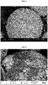
- the sintered granules made according the present invention have a surface region with a metal binder content less than the metal binder content in the inner part of the granules.
- the depletion of the metal binder in the surface region can most easily be seen in a SEM image of a granule where it can be seen that the surface of the granule is covered with WC crystals.
- the metal binder can sometimes be seen in the bottom of larger gaps in between the WC grains, however not on the actual surface of the granule. See e.g. Figure 1 .
- the sintered granules are usually spherical, or have a rounded shape which it achieved from the spray drying step. Since the granules is not sintered together during sintering, the shape that they achieved from the spray drying can be maintained.
- an unsintered granule is herein meant a compact particle comprising an organic binder and particles of hard constituents and binder metal.
- sintered granule is herein meant a compact particle comprising particles of hard constituents embedded in a binder metal matrix.
- cermet a material comprising hard constituents in a metallic binder phase, wherein the hard constituents comprise carbides or carbonitrides of one or more of Ta, Ti, Nb, Cr, Hf, V, Mo and Zr, such as TiN, TiC and/or TiCN.
- cemented carbide powder a material comprising hard constituents in a metallic binder phase, wherein the hard constituents comprise at least 50 wt% WC grains.
- the hard constituents can also comprise carbides or carbonitrides of one or more of Ta, Ti, Nb, Cr, Hf, V, Mo and Zr, such as TiN, TiC and/or TiCN.
- the present invention also relates to the use of the ready-to-print powder described above for making a cermet or cemented carbide body by additive manufacturing, like three dimensional printing.
- the three dimensional printing is binder jetting.
- Binder jetting is advantageous in that it is a relatively cheap three dimensional printing method.
- 3D printing of cermet or cemented carbide pieces are known in the art and the exact printing parameters are up to the person skilled in the art to determine based on the type of printing technology that is used. Usually, the printing step is followed by curing and depowdering, and then a sintering step where the final cermet or cemented carbide piece is achieved.
- RTP powders was used as raw material comprising WC, metallic binder and carbides of Cr and when present Ta and Nb.
- the composition of the different powders based on the elements are shown in Table 1 where the balance is carbon.
- the WC grain size (FSSS) in Invention 1 and 2 are 0.80 ⁇ m and for Invention 3 1.5 ⁇ m.
- the RTP powders also contained 2 wt% PEG, not included in the dry powder weight.
- a new slurry was made by dissolving the RTP powder into a solvent of ethanol and water in a ratio of 78/22 and by adding 2 wt% extra PEG.
- the slurry was spray dried to small granules with a D50 around 25um.
- the unsintered granules were placed in a sintering furnace on a graphite tray coated with yttrium oxide and was first subjected to a debinding step in hydrogen atmosphere which included a stepwise increase in temperature to 500°C for a time of 170 min. Then the temperature was increased in a Ar atmosphere (200mBar partial pressure) to the maximum sintering temperature of 1275°C where CO and Ar were introduced at a 1:1 flow ratio at 250mbar partial pressure. The temperature and CO/Ar atmosphere was maintained for 60 min. After that, the granules were cooled down to room temperature by free cooling.
- the powder were then sieved at 63 ⁇ m.
- the resulting cemented carbide powder comprising sintered granules is herein denoted Invention 1-3.
- FIG. 1 A SEM image of a sintered granule of Invention 1 is shown in Figure 1 .
- Table 1 Sample W [wt%] Co [wt%] Cr [wt%] Ta [wt%] Nb [wt%] Invention 1 84.1 10 0.43 0 0 Invention 2 81.4 13 0.56 0 0 Invention 3 81.1 12 0 1.35 0.15
- the particle size of the sintered granules was measured by Laser diffraction of the dry granules in an interval of 0.5 and 175 ⁇ m. The results are shown in Table 2.
- Table 2 Sample D10 D50 D90 Invention 1 7.8 18.4 32.1 Invention 2 8.4 18.7 32.6 Invention 3 8.5 19.7 35.5
- the porosity was measured by image analysis on a LOM (Light optic microscope) image (2000 magnification) on a cross section of a granule using the software Image J. An average of approx. 50 granules was analyzed per powder sample. The powder sintered at 1300°C was noticeable more difficult to deagglomerate and thus the granules were deformed to a higher extent compared to 1250 and 1275°C.
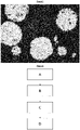
- Sintered granules were made from a powder having the same composition as Invention 1 in Example 1 according to the process described in US 2017/0072469 using graphite powder as a physical barrier. The graphite powder was removed after sintering. A SEM image of a sintered granule is shown in Figure 2 .
- the sintered granules, Invention 2 from Example 1, was used to print sample cubes (15x15x6mm).
- the cubes were produced through binder jet printing.
- the printing was done using a ExOne Innovent+ with a layer thickness of 50um during the printing. Saturation during the printing was set to 80%.
- the cubes were then sintered with a high pressure sintering cycle with a maximum temperature 1410°C for 90 minutes. In the end of the cycle 50bar high pressure was applied. All physical properties were within the specification for this substrate if would have been made using conventional methods i.e. compaction instead of printing as forming step.
- Table 4 Granules Hc [kA/m] Com [%] Density [g/cm 3 ] Porosity A B C Invention 2 16.3 11.6 14.10 02 00 00 00
Abstract
Description
- The present invention relates to a method of making a sintered, ready- to -print cermet or cemented carbide powder and also a powder made by such a process. The powder is suitable for additive manufacturing like 3D printing of cemented carbide bodies.
- Three dimensional (3D) printing or additive manufacturing is a promising manufacturing technique that makes it possible to print a three dimensional body. Three dimensional printing is a promising manufacturing technique because it makes it possible to produce complex structures and bodies that cannot be achieved via conventional manufacturing processes.
- Making cermet or cemented carbide bodies using 3D printing is known in the art. Cermet and cemented carbide materials consist of hard constituents of carbides and/or nitrides such as WC or TiC in a metallic binder phase of for example Co. These materials are useful in high demanding applications due to their high hardness and high wear resistance in combination with a high toughness. Examples of areas of application are cutting tools for metal cutting, drill bits for rock drilling and wear parts.
- One of the challenges when producing cermet and cemented carbide materials using 3D printing is to provide a body with comparable microstructure, i.e. porosity, minimum of Co islands etc. as conventionally produced cermet and cemented carbide materials, i.e. formed by pressing.
- However, there has been many attempts to find a suitably powder that is both easy to manufacture, has the appropriate characteristics for 3D printing and which also results in a final sintered cemented carbide with good quality.
- In conventional production of cemented carbide bodies using milling, spray drying, pressing and sintering, the powder used in the pressing is not sintered, however for 3D printing, such a powder is too fragile and also too porous. Therefore, the dried powder in the form of granules are sintered to different degrees when used in 3D printing. However, this can cause the granules to adhere to each other since the metal binder at the surface of the granules easily melt together. The sintered powder thus needs to be milled or crushed using extensive force in order to be used in 3D printing. This will lead to non-spherical grains after milling/crushing of the sintered granules which can affect the flowability of the powder.
- One way to prevent the granules from sinter together is to use a lower sintering temperature thus forming less metal binder on the surface on the granules, however that lead to less dense granules with more pores. If the granules are too porous, the 3D printed cemented carbide can, after the final sintering, still have pores.
- There has also been attempts to prevent the granules from sinter together by physically prevent contact between the granules by e.g. add a powder that can function as a barrier. However, such a process also requires several cleaning steps after sintering to remove the barrier powder before the final powder can be used in 3D printing.
- It is an object of the present invention to obtain a method of making a cermet or cemented carbide powder for additive manufacturing which prevents the granules from sintering to each other.
- It is an object of the present invention to obtain a method of making a cermet or cemented carbide powder for additive manufacturing which is easy and requires few steps.
- It is an object of the present invention to obtain a method of making a cermet or cemented carbide powder for additive manufacturing that has an appropriate porosity a good flowability.
- The present invention relates to a method of making a powder according to the above. The method comprises the following steps:
- forming a slurry comprising hard constituents, binder metal, organic binder and a solvent;
- from the slurry forming unsintered granules comprising hard constituents, binder metal and organic binder
- loading the unsintered granules in a furnace
- sintering the granules at a temperature between 1200 and Ts°C, where Ts is the highest temperature where the binder is still in a solid state for a specific cermet or cemented carbide composition, in a carburizing atmosphere to form sintered granules;
- subjecting the sintered granules to a deagglomeration step whereby a powder of sintered granules is formed.
- The slurry comprises powders forming hard constituents, binder metal, organic binder and a solvent.
- By powders forming hard constituents are herein meant powders selected from carbides, nitrides or carbonitrides of one or more elements of W, Ta, Ti, Nb, Nb, Cr and V.
- When making a cemented carbide powder, the hard constituents comprise at least 50 wt% WC grains. The hard constituents can also comprise carbides or carbonitrides of one or more of Ta, Ti, Nb, Cr, Hf, V, Mo and Zr, such as TiN, TiC and/or TiCN.
- When making a cermet powder, the hard constituents comprise carbides or carbonitrides of one or more of Ta, Ti, Nb, Cr, Hf, V, Mo and Zr, such as TiN, TiC and/or TiCN.
- By metal binder is herein meant one or more elements selected from Co, Ni and Fe, preferably Co. The amount of metal binder in the slurry is suitably between 5 and 14 wt%, preferably between 8 and 14 wt% based on the dry powder weight. The metallic binder phase content is herein calculated excluding the organic binder and solvent.
- The organic binder is suitably selected from Polyethyleglycol (PEG) or wax. The amount of organic binder can be between 1 and 5 wt% based on the powder weight.
- The solvent can be any solvent suitably for making a slurry, preferably a mixture of water and alcohol.
- The forming of the unsintered granules is suitably done by using spray drying or any other suitable technique that can form spherical granules.
- The unsintered granules are placed in a furnace on a tray. Preferably, the tray of graphite and is coated with yttrium oxide to prevent the powder from sticking to the tray.
- The first part of the sintering cycle is a debinding step where the organic binder is removed. Suitably this is done at a temperature of between 200 and 550°C for a period of time of between 5 and 240 minutes. The debinding can also be done in more than one step, i.e. by stepwise increasing the temperature. The exact debinding process depends on several things, like e.g. furnace type, batch size, type of binder etc.
- The second part of the sintering, i.e. the solid state sintering, takes place at a temperature is above 1200 and below Ts °C, where Ts is the highest temperature where the binder is still in a solid state for a specific cermet or cemented carbide composition. This temperature is usually displayed as a line called "solidus" in the phase diagram for each specific cermet or cemented carbide composition. The solid state sintering is performed for a time period of between 5 and 60 minutes. Preferably, the sintering takes place at a temperature of between 1250 and Ts°C, and more preferably between 1250 and 1300°C.
- When deciding on the exact sintering temperature, the specific cermet or cemented carbide composition has to be taken into account.
- In one embodiment of the present invention, when the metallic binder is Co, the sintering takes place at a temperature between 1250 and 1300°C, preferably between 1260 and 1290°C.
- By carburizing atmosphere is herein meant that carbon is added to the furnace. This can be done in several ways, like e.g. one or more carbon containing gases, e.g. CO, CH4, CO2. Some carbon contribution can also come from the furnace if it is a graphite furnace.
- Preferably the carburizing atmosphere is created by a carbon containing gas, preferably CO, CO2 and/or CH4. The partial pressure of the carburizing gas should be at least 50 mBar, preferably at least 75 mBar of the total amount of gas present. The partial pressure of the carburizing gas should be below atmospheric pressure. Other suitable gases that can be present are Ar, H2 etc. The total pressure in the sintering furnace should be below atmospheric pressure.
- After sintering, the granules are usually adhered to each other with weak forces. Only a gentle deagglomeration needs to be performed in order to obtain the final powder. The de-agglomeration is preferably done by a gentle milling in a ball mill without milling liquid etc. If smaller quantities of granules are to be deagglomerated, it can be done by hand using a mortar.
- Since the granules are not sintered together but instead are only weakly adhered to each other, the spherical, or rounded shape, achieved from the spray drying step can thus be maintained also after the deagglomeration.
- Before using the sintered granules for 3D printing, the ready-to-print powder comprising sintered granules can be subjected to one or more sieving steps. This can be done for several purposes, like e.g. removing any larger pieces that has not been deagglomerated but also to achieve the desired granule size.
- The present invention also relates to a ready- to -print cermet or cemented carbide powder comprising sintered granules made according to the method as described above.
- By ready- to -print is herein meant that the powder is ready to use in an additive manufacturing process like 3D printing.
- The powder comprises sintered granules with an average diameter (D50) of between 15 and 30 µm comprising WC and a metal binder, wherein the sintered granules have a porosity of between 0.1 and 5 vol%.
- The porosity of the sintered granules can be determined in different ways. One way is to calculate it by first measuring the density of the granules using a pycnometer. The measured density is then compared with the theoretical (or full) density for the specific cermet or cemented carbide composition. The full density can be either determined by calculation using an appropriate software like e.g. Thermocalc or by measuring it on a sintered piece with no pores made from a powder having the same composition . The difference is assumed to be pores.
- Another way of measuring the porosity is to use image analysis on a SEM or LOM image of a cross section of at least 50 sintered granules. The result will then be given in area% but is assumed to be the same value in vol%.
- The sintered granules made according the present invention have a surface region with a metal binder content less than the metal binder content in the inner part of the granules.
- The depletion of the metal binder in the surface region can most easily be seen in a SEM image of a granule where it can be seen that the surface of the granule is covered with WC crystals. The metal binder can sometimes be seen in the bottom of larger gaps in between the WC grains, however not on the actual surface of the granule. See e.g.
Figure 1 . - The sintered granules are usually spherical, or have a rounded shape which it achieved from the spray drying step. Since the granules is not sintered together during sintering, the shape that they achieved from the spray drying can be maintained.
- By an unsintered granule is herein meant a compact particle comprising an organic binder and particles of hard constituents and binder metal.
- By sintered granule is herein meant a compact particle comprising particles of hard constituents embedded in a binder metal matrix.
- By cermet is herein meant a material comprising hard constituents in a metallic binder phase, wherein the hard constituents comprise carbides or carbonitrides of one or more of Ta, Ti, Nb, Cr, Hf, V, Mo and Zr, such as TiN, TiC and/or TiCN.
- By cemented carbide powder is herein meant a material comprising hard constituents in a metallic binder phase, wherein the hard constituents comprise at least 50 wt% WC grains. The hard constituents can also comprise carbides or carbonitrides of one or more of Ta, Ti, Nb, Cr, Hf, V, Mo and Zr, such as TiN, TiC and/or TiCN.
- The present invention also relates to the use of the ready-to-print powder described above for making a cermet or cemented carbide body by additive manufacturing, like three dimensional printing.
- In one embodiment of the present invention the three dimensional printing is binder jetting. Binder jetting is advantageous in that it is a relatively cheap three dimensional printing method.
- 3D printing of cermet or cemented carbide pieces are known in the art and the exact printing parameters are up to the person skilled in the art to determine based on the type of printing technology that is used. Usually, the printing step is followed by curing and depowdering, and then a sintering step where the final cermet or cemented carbide piece is achieved.
-
-
Figure 1 shows a SEM Image of a sintered granule made according to the present invention. -
Figure 2 shows a SEM Image of a sintered granule made according to the prior art. -
Figure 3 shows a LOM image of a cross section of a granule. -
Figure 4 shows the different steps where step A is forming unsintered granules, step B is loading the unsintered granules into a furnace, step C is sintering the unsintered granules in a carburizing atmosphere and step D is subjecting the sintered granules to a deagglomeration step. - Already milled and spray dried ready-to-press (RTP) powders was used as raw material comprising WC, metallic binder and carbides of Cr and when present Ta and Nb. The composition of the different powders based on the elements are shown in Table 1 where the balance is carbon. The WC grain size (FSSS) in Invention 1 and 2 are 0.80 µm and for Invention 3 1.5 µm. In addition to the powder raw materials, the RTP powders also contained 2 wt% PEG, not included in the dry powder weight.
- A new slurry was made by dissolving the RTP powder into a solvent of ethanol and water in a ratio of 78/22 and by adding 2 wt% extra PEG. The slurry was spray dried to small granules with a D50 around 25um.
- The unsintered granules were placed in a sintering furnace on a graphite tray coated with yttrium oxide and was first subjected to a debinding step in hydrogen atmosphere which included a stepwise increase in temperature to 500°C for a time of 170 min. Then the temperature was increased in a Ar atmosphere (200mBar partial pressure) to the maximum sintering temperature of 1275°C where CO and Ar were introduced at a 1:1 flow ratio at 250mbar partial pressure. The temperature and CO/Ar atmosphere was maintained for 60 min. After that, the granules were cooled down to room temperature by free cooling.
- The sintering resulted in a cake of sintered granules which was subjected to a deagglomeration which was done in a ball mill using 100kg cylpebs with 30kg powder. The ball milled was ran dry without any milling liquid. The deagglomeration time was between 10 to 40min depending on sample.
- The powder were then sieved at 63µm.
- The resulting cemented carbide powder comprising sintered granules is herein denoted Invention 1-3.
- A SEM image of a sintered granule of Invention 1 is shown in
Figure 1 .Table 1 Sample W [wt%] Co [wt%] Cr [wt%] Ta [wt%] Nb [wt%] Invention 1 84.1 10 0.43 0 0 Invention 2 81.4 13 0.56 0 0 Invention 3 81.1 12 0 1.35 0.15 Table 2 Sample D10 D50 D90 Invention 1 7.8 18.4 32.1 Invention 2 8.4 18.7 32.6 Invention 3 8.5 19.7 35.5 - The same unsintered granules as used in Invention 1 from Example 1 were sintered in the same way as in Example 1 but at different maximum temperatures using a mix of CO and H2 atmosphere(in a ratio of 1:1 total partial pressure 250mBar) (same for all 3 samples). In the end of the cycle 50bar (Ar) high pressure was applied. The samples are called Invention 1a-c.
- The porosity was measured by image analysis on a LOM (Light optic microscope) image (2000 magnification) on a cross section of a granule using the software Image J. An average of approx. 50 granules was analyzed per powder sample. The powder sintered at 1300°C was noticeable more difficult to deagglomerate and thus the granules were deformed to a higher extent compared to 1250 and 1275°C.
Table 3 Invention 1a Invention 1b Invention 1c Sintering Temp. (°C) 1250 1275 1300 Porosity [area%] 11.1 3.1 0.42 - Sintered granules were made from a powder having the same composition as Invention 1 in Example 1 according to the process described in
US 2017/0072469 using graphite powder as a physical barrier. The graphite powder was removed after sintering. A SEM image of a sintered granule is shown inFigure 2 . - The sintered granules, Invention 2 from Example 1, was used to print sample cubes (15x15x6mm). The cubes were produced through binder jet printing. The printing was done using a ExOne Innovent+ with a layer thickness of 50um during the printing. Saturation during the printing was set to 80%. The cubes were then sintered with a high pressure sintering cycle with a maximum temperature 1410°C for 90 minutes. In the end of the cycle 50bar high pressure was applied. All physical properties were within the specification for this substrate if would have been made using conventional methods i.e. compaction instead of printing as forming step.
Table 4 Granules Hc [kA/m] Com [%] Density [g/cm3] Porosity A B C Invention 2 16.3 11.6 14.10 02 00 00
Claims (14)
- A method of making a ready-to-print cermet or cemented carbide powder comprising sintered granules comprising the following steps:- forming a slurry comprising hard constituents, binder metal, organic binder and a solvent;- from the slurry, forming unsintered granules comprising hard constituents, binder metal and organic binder- loading the unsintered granules in a furnace- sintering the granules at a temperature between 1200 and Ts °C, where Ts is the highest temperature where the binder is still in a solid state for a specific cermet or cemented carbide composition, in a carburizing atmosphere to form sintered granules;- subjecting the sintered granules to a deagglomeration step whereby a powder of granules is formed.
- A method according to claim 1 wherein the carburizing atmosphere is provided by one or more carburizing gases selected from CO, CO2 and CH4.
- A method according to claim 2 wherein the carburizing gas is present at a partial pressure of at least 50 mBar.
- A method according to any of the preceding claims wherein the ready-to-print powder is a cemented carbide powder wherein the hard constituents comprise at least 50 wt% WC grains.
- A method according to any of the preceding claims wherein the metal binder is one or more elements selected from Co, Ni and Fe and wherein the amount metal binder is between 5 and 14 wt% based on dry powder weight.
- A method according to any of the preceding claims wherein the sintering temperature is between 1250 and 1300°C.
- A method according to any of the preceding claims the metallic binder is Co and the sintering temperature is between 1260 and 1290°C.
- A method according to any of the preceding claims wherein the ready-to-print cermet or cemented carbide powder comprising sintered granules are subjected to one or more sieving steps.
- A ready-to-print cermet or cemented carbide powder comprising sintered granules made according to the method of claims 1-8.
- A ready-to-print cermet or cemented carbide powder according to claim 9 wherein the granules have a average particle size of between 15 and 30 µm.
- A ready-to-print cermet or cemented carbide powder according to any of claims 9-10 wherein the porosity of the granules is between 0.1 and 5vol%.
- A ready-to-print cermet or cemented carbide powder according to any of claims 9-11 wherein the powder is a cemented carbide powder.
- Use of the ready-to-print cermet or cemented carbide powder according to any of claims 9-12 in an additive manufacturing process for making a cermet or cemented carbide body.
- Use of the ready-to-print cermet or cemented carbide powder according to claim 13 wherein the additive manufacturing process is binder jetting.
Priority Applications (3)
| Application Number | Priority Date | Filing Date | Title |
|---|---|---|---|
| EP21183255.5A EP4112206A1 (en) | 2021-07-01 | 2021-07-01 | Method of making a powder for additive manufacturing |
| CN202280045473.6A CN117580660A (en) | 2021-07-01 | 2022-06-23 | Method for preparing powder for additive manufacturing |
| PCT/EP2022/067077 WO2023274818A1 (en) | 2021-07-01 | 2022-06-23 | Method of making a powder for additive manufacturing |
Applications Claiming Priority (1)
| Application Number | Priority Date | Filing Date | Title |
|---|---|---|---|
| EP21183255.5A EP4112206A1 (en) | 2021-07-01 | 2021-07-01 | Method of making a powder for additive manufacturing |
Publications (1)
| Publication Number | Publication Date |
|---|---|
| EP4112206A1 true EP4112206A1 (en) | 2023-01-04 |
Family
ID=76744761
Family Applications (1)
| Application Number | Title | Priority Date | Filing Date |
|---|---|---|---|
| EP21183255.5A Pending EP4112206A1 (en) | 2021-07-01 | 2021-07-01 | Method of making a powder for additive manufacturing |
Country Status (3)
| Country | Link |
|---|---|
| EP (1) | EP4112206A1 (en) |
| CN (1) | CN117580660A (en) |
| WO (1) | WO2023274818A1 (en) |
Families Citing this family (1)
| Publication number | Priority date | Publication date | Assignee | Title |
|---|---|---|---|---|
| CN116041051B (en) * | 2023-01-16 | 2024-03-22 | 广东工业大学 | Granulating powder applied to 3DP printing and printing forming method thereof |
Citations (3)
| Publication number | Priority date | Publication date | Assignee | Title |
|---|---|---|---|---|
| US20170072469A1 (en) | 2014-04-24 | 2017-03-16 | Sandvik Intelectual Property Ab | Method of making cermet or cemented carbide powder |
| WO2021004776A1 (en) * | 2019-07-05 | 2021-01-14 | Sandvik Machining Solutions Ab | Three dimensional printing of cermet or cemented carbide |
| WO2021122520A1 (en) * | 2019-12-19 | 2021-06-24 | Ab Sandvik Coromant | Gradient cemented carbide with alternative binder |
-
2021
- 2021-07-01 EP EP21183255.5A patent/EP4112206A1/en active Pending
-
2022
- 2022-06-23 WO PCT/EP2022/067077 patent/WO2023274818A1/en active Application Filing
- 2022-06-23 CN CN202280045473.6A patent/CN117580660A/en active Pending
Patent Citations (3)
| Publication number | Priority date | Publication date | Assignee | Title |
|---|---|---|---|---|
| US20170072469A1 (en) | 2014-04-24 | 2017-03-16 | Sandvik Intelectual Property Ab | Method of making cermet or cemented carbide powder |
| WO2021004776A1 (en) * | 2019-07-05 | 2021-01-14 | Sandvik Machining Solutions Ab | Three dimensional printing of cermet or cemented carbide |
| WO2021122520A1 (en) * | 2019-12-19 | 2021-06-24 | Ab Sandvik Coromant | Gradient cemented carbide with alternative binder |
Also Published As
| Publication number | Publication date |
|---|---|
| WO2023274818A1 (en) | 2023-01-05 |
| CN117580660A (en) | 2024-02-20 |
Similar Documents
| Publication | Publication Date | Title |
|---|---|---|
| EP3442729B1 (en) | Cermet or cemented carbide mixture and three dimensional printing thereof | |
| KR102229047B1 (en) | Method of making a cemented carbide or cermet powder by using a resonant acoustic mixer | |
| EP1925383B1 (en) | Method of making a sintered body, a powder mixture and a sintered body | |
| CN106573298A (en) | A method of making cermet or cemented carbide powder | |
| EP2433727B1 (en) | Method for producing a sintered composite body | |
| WO2021004776A1 (en) | Three dimensional printing of cermet or cemented carbide | |
| EP4112206A1 (en) | Method of making a powder for additive manufacturing | |
| US20240093336A1 (en) | Printable and sinterable cemented carbide and cermet powders for powder bed-based additive manufacturing | |
| JP5057751B2 (en) | Cemented carbide and method for producing the same | |
| KR20130076451A (en) | Method for producing high strength and high toughness cemented carbide material | |
| EP2584057B1 (en) | Method of making a cemented carbide or cermet powder by using a resonant acoustic mixer | |
| WO2023201141A1 (en) | Cemented carbide powder for binder jet additive manufacturing | |
| KR20220131542A (en) | Polycrystalline cubic boron nitride material | |
| WO2023114632A1 (en) | Cemented carbide and cermet compositions having a high-entropy-alloy binder | |
| JPH09203285A (en) | Multi-layer cemented carbide chip and production |
Legal Events
| Date | Code | Title | Description |
|---|---|---|---|
| PUAI | Public reference made under article 153(3) epc to a published international application that has entered the european phase |
Free format text: ORIGINAL CODE: 0009012 |
|
| STAA | Information on the status of an ep patent application or granted ep patent |
Free format text: STATUS: THE APPLICATION HAS BEEN PUBLISHED |
|
| AK | Designated contracting states |
Kind code of ref document: A1 Designated state(s): AL AT BE BG CH CY CZ DE DK EE ES FI FR GB GR HR HU IE IS IT LI LT LU LV MC MK MT NL NO PL PT RO RS SE SI SK SM TR |
|
| STAA | Information on the status of an ep patent application or granted ep patent |
Free format text: STATUS: REQUEST FOR EXAMINATION WAS MADE |
|
| 17P | Request for examination filed |
Effective date: 20230704 |
|
| RBV | Designated contracting states (corrected) |
Designated state(s): AL AT BE BG CH CY CZ DE DK EE ES FI FR GB GR HR HU IE IS IT LI LT LU LV MC MK MT NL NO PL PT RO RS SE SI SK SM TR |