EP4112087B1 - Epidemic prevention channel and epidemic prevention method - Google Patents
Epidemic prevention channel and epidemic prevention method Download PDFInfo
- Publication number
- EP4112087B1 EP4112087B1 EP20921680.3A EP20921680A EP4112087B1 EP 4112087 B1 EP4112087 B1 EP 4112087B1 EP 20921680 A EP20921680 A EP 20921680A EP 4112087 B1 EP4112087 B1 EP 4112087B1
- Authority
- EP
- European Patent Office
- Prior art keywords
- air
- filtering
- exhaust
- channel body
- channel
- Prior art date
- Legal status (The legal status is an assumption and is not a legal conclusion. Google has not performed a legal analysis and makes no representation as to the accuracy of the status listed.)
- Active
Links
Images
Classifications
-
- A—HUMAN NECESSITIES
- A61—MEDICAL OR VETERINARY SCIENCE; HYGIENE
- A61L—METHODS OR APPARATUS FOR STERILISING MATERIALS OR OBJECTS IN GENERAL; DISINFECTION, STERILISATION OR DEODORISATION OF AIR; CHEMICAL ASPECTS OF BANDAGES, DRESSINGS, ABSORBENT PADS OR SURGICAL ARTICLES; MATERIALS FOR BANDAGES, DRESSINGS, ABSORBENT PADS OR SURGICAL ARTICLES
- A61L2/00—Disinfection or sterilisation of materials or objects, in general; Accessories therefor
- A61L2/16—Disinfection or sterilisation of materials or objects, in general; Accessories therefor using chemical substances
- A61L2/18—Liquid substances
-
- A—HUMAN NECESSITIES
- A61—MEDICAL OR VETERINARY SCIENCE; HYGIENE
- A61L—METHODS OR APPARATUS FOR STERILISING MATERIALS OR OBJECTS IN GENERAL; DISINFECTION, STERILISATION OR DEODORISATION OF AIR; CHEMICAL ASPECTS OF BANDAGES, DRESSINGS, ABSORBENT PADS OR SURGICAL ARTICLES; MATERIALS FOR BANDAGES, DRESSINGS, ABSORBENT PADS OR SURGICAL ARTICLES
- A61L9/00—Disinfection, sterilisation or deodorisation of air
- A61L9/14—Disinfection, sterilisation or deodorisation of air using sprayed or atomised substances including air-liquid contact processes
- A61L9/145—Disinfection, sterilisation or deodorisation of air using sprayed or atomised substances including air-liquid contact processes air-liquid contact processes, e.g. scrubbing
-
- A—HUMAN NECESSITIES
- A61—MEDICAL OR VETERINARY SCIENCE; HYGIENE
- A61L—METHODS OR APPARATUS FOR STERILISING MATERIALS OR OBJECTS IN GENERAL; DISINFECTION, STERILISATION OR DEODORISATION OF AIR; CHEMICAL ASPECTS OF BANDAGES, DRESSINGS, ABSORBENT PADS OR SURGICAL ARTICLES; MATERIALS FOR BANDAGES, DRESSINGS, ABSORBENT PADS OR SURGICAL ARTICLES
- A61L9/00—Disinfection, sterilisation or deodorisation of air
- A61L9/16—Disinfection, sterilisation or deodorisation of air using physical phenomena
-
- A—HUMAN NECESSITIES
- A61—MEDICAL OR VETERINARY SCIENCE; HYGIENE
- A61L—METHODS OR APPARATUS FOR STERILISING MATERIALS OR OBJECTS IN GENERAL; DISINFECTION, STERILISATION OR DEODORISATION OF AIR; CHEMICAL ASPECTS OF BANDAGES, DRESSINGS, ABSORBENT PADS OR SURGICAL ARTICLES; MATERIALS FOR BANDAGES, DRESSINGS, ABSORBENT PADS OR SURGICAL ARTICLES
- A61L9/00—Disinfection, sterilisation or deodorisation of air
- A61L9/16—Disinfection, sterilisation or deodorisation of air using physical phenomena
- A61L9/18—Radiation
- A61L9/20—Ultraviolet radiation
-
- B—PERFORMING OPERATIONS; TRANSPORTING
- B01—PHYSICAL OR CHEMICAL PROCESSES OR APPARATUS IN GENERAL
- B01D—SEPARATION
- B01D46/00—Filters or filtering processes specially modified for separating dispersed particles from gases or vapours
- B01D46/0027—Filters or filtering processes specially modified for separating dispersed particles from gases or vapours with additional separating or treating functions
- B01D46/0028—Filters or filtering processes specially modified for separating dispersed particles from gases or vapours with additional separating or treating functions provided with antibacterial or antifungal means
-
- B—PERFORMING OPERATIONS; TRANSPORTING
- B01—PHYSICAL OR CHEMICAL PROCESSES OR APPARATUS IN GENERAL
- B01D—SEPARATION
- B01D46/00—Filters or filtering processes specially modified for separating dispersed particles from gases or vapours
- B01D46/56—Filters or filtering processes specially modified for separating dispersed particles from gases or vapours with multiple filtering elements, characterised by their mutual disposition
-
- F—MECHANICAL ENGINEERING; LIGHTING; HEATING; WEAPONS; BLASTING
- F24—HEATING; RANGES; VENTILATING
- F24F—AIR-CONDITIONING; AIR-HUMIDIFICATION; VENTILATION; USE OF AIR CURRENTS FOR SCREENING
- F24F11/00—Control or safety arrangements
- F24F11/0001—Control or safety arrangements for ventilation
-
- F—MECHANICAL ENGINEERING; LIGHTING; HEATING; WEAPONS; BLASTING
- F24—HEATING; RANGES; VENTILATING
- F24F—AIR-CONDITIONING; AIR-HUMIDIFICATION; VENTILATION; USE OF AIR CURRENTS FOR SCREENING
- F24F13/00—Details common to, or for air-conditioning, air-humidification, ventilation or use of air currents for screening
- F24F13/28—Arrangement or mounting of filters
-
- F—MECHANICAL ENGINEERING; LIGHTING; HEATING; WEAPONS; BLASTING
- F24—HEATING; RANGES; VENTILATING
- F24F—AIR-CONDITIONING; AIR-HUMIDIFICATION; VENTILATION; USE OF AIR CURRENTS FOR SCREENING
- F24F3/00—Air-conditioning systems in which conditioned primary air is supplied from one or more central stations to distributing units in the rooms or spaces where it may receive secondary treatment; Apparatus specially designed for such systems
- F24F3/12—Air-conditioning systems in which conditioned primary air is supplied from one or more central stations to distributing units in the rooms or spaces where it may receive secondary treatment; Apparatus specially designed for such systems characterised by the treatment of the air otherwise than by heating and cooling
- F24F3/16—Air-conditioning systems in which conditioned primary air is supplied from one or more central stations to distributing units in the rooms or spaces where it may receive secondary treatment; Apparatus specially designed for such systems characterised by the treatment of the air otherwise than by heating and cooling by purification, e.g. by filtering; by sterilisation; by ozonisation
-
- F—MECHANICAL ENGINEERING; LIGHTING; HEATING; WEAPONS; BLASTING
- F24—HEATING; RANGES; VENTILATING
- F24F—AIR-CONDITIONING; AIR-HUMIDIFICATION; VENTILATION; USE OF AIR CURRENTS FOR SCREENING
- F24F8/00—Treatment, e.g. purification, of air supplied to human living or working spaces otherwise than by heating, cooling, humidifying or drying
- F24F8/10—Treatment, e.g. purification, of air supplied to human living or working spaces otherwise than by heating, cooling, humidifying or drying by separation, e.g. by filtering
-
- F—MECHANICAL ENGINEERING; LIGHTING; HEATING; WEAPONS; BLASTING
- F24—HEATING; RANGES; VENTILATING
- F24F—AIR-CONDITIONING; AIR-HUMIDIFICATION; VENTILATION; USE OF AIR CURRENTS FOR SCREENING
- F24F8/00—Treatment, e.g. purification, of air supplied to human living or working spaces otherwise than by heating, cooling, humidifying or drying
- F24F8/10—Treatment, e.g. purification, of air supplied to human living or working spaces otherwise than by heating, cooling, humidifying or drying by separation, e.g. by filtering
- F24F8/108—Treatment, e.g. purification, of air supplied to human living or working spaces otherwise than by heating, cooling, humidifying or drying by separation, e.g. by filtering using dry filter elements
-
- F—MECHANICAL ENGINEERING; LIGHTING; HEATING; WEAPONS; BLASTING
- F24—HEATING; RANGES; VENTILATING
- F24F—AIR-CONDITIONING; AIR-HUMIDIFICATION; VENTILATION; USE OF AIR CURRENTS FOR SCREENING
- F24F8/00—Treatment, e.g. purification, of air supplied to human living or working spaces otherwise than by heating, cooling, humidifying or drying
- F24F8/10—Treatment, e.g. purification, of air supplied to human living or working spaces otherwise than by heating, cooling, humidifying or drying by separation, e.g. by filtering
- F24F8/117—Treatment, e.g. purification, of air supplied to human living or working spaces otherwise than by heating, cooling, humidifying or drying by separation, e.g. by filtering using wet filtering
- F24F8/133—Treatment, e.g. purification, of air supplied to human living or working spaces otherwise than by heating, cooling, humidifying or drying by separation, e.g. by filtering using wet filtering by direct contact with liquid, e.g. with sprayed liquid
-
- F—MECHANICAL ENGINEERING; LIGHTING; HEATING; WEAPONS; BLASTING
- F24—HEATING; RANGES; VENTILATING
- F24F—AIR-CONDITIONING; AIR-HUMIDIFICATION; VENTILATION; USE OF AIR CURRENTS FOR SCREENING
- F24F8/00—Treatment, e.g. purification, of air supplied to human living or working spaces otherwise than by heating, cooling, humidifying or drying
- F24F8/20—Treatment, e.g. purification, of air supplied to human living or working spaces otherwise than by heating, cooling, humidifying or drying by sterilisation
-
- F—MECHANICAL ENGINEERING; LIGHTING; HEATING; WEAPONS; BLASTING
- F24—HEATING; RANGES; VENTILATING
- F24F—AIR-CONDITIONING; AIR-HUMIDIFICATION; VENTILATION; USE OF AIR CURRENTS FOR SCREENING
- F24F8/00—Treatment, e.g. purification, of air supplied to human living or working spaces otherwise than by heating, cooling, humidifying or drying
- F24F8/20—Treatment, e.g. purification, of air supplied to human living or working spaces otherwise than by heating, cooling, humidifying or drying by sterilisation
- F24F8/22—Treatment, e.g. purification, of air supplied to human living or working spaces otherwise than by heating, cooling, humidifying or drying by sterilisation using UV light
-
- A—HUMAN NECESSITIES
- A61—MEDICAL OR VETERINARY SCIENCE; HYGIENE
- A61L—METHODS OR APPARATUS FOR STERILISING MATERIALS OR OBJECTS IN GENERAL; DISINFECTION, STERILISATION OR DEODORISATION OF AIR; CHEMICAL ASPECTS OF BANDAGES, DRESSINGS, ABSORBENT PADS OR SURGICAL ARTICLES; MATERIALS FOR BANDAGES, DRESSINGS, ABSORBENT PADS OR SURGICAL ARTICLES
- A61L2209/00—Aspects relating to disinfection, sterilisation or deodorisation of air
- A61L2209/10—Apparatus features
- A61L2209/11—Apparatus for controlling air treatment
-
- A—HUMAN NECESSITIES
- A61—MEDICAL OR VETERINARY SCIENCE; HYGIENE
- A61L—METHODS OR APPARATUS FOR STERILISING MATERIALS OR OBJECTS IN GENERAL; DISINFECTION, STERILISATION OR DEODORISATION OF AIR; CHEMICAL ASPECTS OF BANDAGES, DRESSINGS, ABSORBENT PADS OR SURGICAL ARTICLES; MATERIALS FOR BANDAGES, DRESSINGS, ABSORBENT PADS OR SURGICAL ARTICLES
- A61L2209/00—Aspects relating to disinfection, sterilisation or deodorisation of air
- A61L2209/10—Apparatus features
- A61L2209/14—Filtering means
-
- F—MECHANICAL ENGINEERING; LIGHTING; HEATING; WEAPONS; BLASTING
- F24—HEATING; RANGES; VENTILATING
- F24F—AIR-CONDITIONING; AIR-HUMIDIFICATION; VENTILATION; USE OF AIR CURRENTS FOR SCREENING
- F24F11/00—Control or safety arrangements
- F24F11/0001—Control or safety arrangements for ventilation
- F24F2011/0002—Control or safety arrangements for ventilation for admittance of outside air
-
- Y—GENERAL TAGGING OF NEW TECHNOLOGICAL DEVELOPMENTS; GENERAL TAGGING OF CROSS-SECTIONAL TECHNOLOGIES SPANNING OVER SEVERAL SECTIONS OF THE IPC; TECHNICAL SUBJECTS COVERED BY FORMER USPC CROSS-REFERENCE ART COLLECTIONS [XRACs] AND DIGESTS
- Y02—TECHNOLOGIES OR APPLICATIONS FOR MITIGATION OR ADAPTATION AGAINST CLIMATE CHANGE
- Y02A—TECHNOLOGIES FOR ADAPTATION TO CLIMATE CHANGE
- Y02A50/00—TECHNOLOGIES FOR ADAPTATION TO CLIMATE CHANGE in human health protection, e.g. against extreme weather
- Y02A50/20—Air quality improvement or preservation, e.g. vehicle emission control or emission reduction by using catalytic converters
Definitions
- the disclosure belongs to an epidemic prevention technology, and in particular, the invention relates to an epidemic prevention channel and an epidemic prevention method.
- an epidemic prevention channel can be set up at the entrance of the building to carry out epidemic prevention and control work.
- a set of return air circulation, ventilation, and purification system is mainly used to circulate and purify the internal air in the closed channel.
- side-to-side blowing or a combination of side-to-side blowing and top-down blowing is used to shower and purify the surface of the personnel. If an infected person enters the channel, after the return air circulates, the virus exhaled by the infected person may continue to exist in the channel, making the personnel who enter the channel later face the risk of cross-infection. As a result, the epidemic spreads inside the building and leads to serious safety hazards.
- Document KR 2012 0113324A describes a movable disinfection and sterilization apparatus sterilizing contagious viruses using an antiseptic solution and ultraviolet rays.
- the Invention aims to provide an epidemic prevention channel to realize sterilization and to avoid the risk of cross infection at the same time.
- the invention provides an epidemic prevention channel as defined in claim 1, including a channel body, wherein the channel body 1 is provided with an air inlet system, an air return system, and an exhaust system.
- An interior of the channel body is divided into an upper area and a lower area.
- the air inlet system includes air inlets, an air intake fan, a first filtering and sterilizing device, and a first nozzle group formed by a plurality of nozzles installed on a top wall of the channel body and side walls of the upper area.
- the air intake fan introduces external fresh air through the air inlets, the external fresh air passes through the air inlets, the air intake fan, the first filtering and sterilizing device, and the first nozzle group in sequence and is then sprayed into and purifies the upper area of the channel body.
- the air return system includes an air return port, an air return fan, a second filtering and sterilizing device, and a second nozzle group formed by a plurality of nozzles installed on side walls of the lower area of the channel body.
- the air in the channel body passes through the air return port, the air return fan, the second filtering and sterilizing device, and the second nozzle group in sequence and circulates, is sprayed into, and purifies the lower area of the channel body.
- the exhaust system includes an exhaust air inlet provided at a bottom of two ends of the channel body, an exhaust pipe communicating with the exhaust air inlet, an exhaust fan, a third filtering and sterilizing device, and an exhaust air outlet.
- the air discharged from the interior of the channel body passes through the exhaust air inlet, the exhaust pipe, the exhaust fan, the third filtering and sterilizing device, and the exhaust air outlet in sequence and flows to the outside of the epidemic prevention channel.
- the epidemic prevention channel provided by the invention may be set at the entrance of places where people gather, such as stations, airports, shopping malls, and communities, to allow the people entering these places to be purified and sterilized.
- the external fresh air is pressurized by the air intake fan first, is sterilized by the first filtering and sterilizing device next, and is finally sprayed into the upper area of the channel body through the first nozzle group.
- the nozzles on the top wall of the channel body spray external fresh air from top to bottom, and the nozzles on the side walls of the upper area spray external fresh air oppositely.
- the air inlet system can quickly remove viruses, bacteria, and dust in the upper area, and can sterilize all parts of a person's body in the upper area through blowing.
- the air return system is used to guide the airflow direction in the channel body, so that the air in the channel body is pressurized by the air return fan, sterilized by the second filtering and sterilizing device, and then sprayed into the lower area of the channel body through the second nozzle group.
- the nozzles on the side walls of the lower area spray the airflow oppositely, and through blowing, all parts of the body in the lower area are fully sprayed and purified.
- the exhaust system is used to extract the air in the channel body, so as to control the pressure difference inside and outside the epidemic prevention channel together with the air inlet system.
- the extracted air is discharged from the exhaust air outlet after being processed by the third filtering and sterilizing device, such that secondary pollution caused by the exhausted air is prevented from being generated.
- the air inlet system, the air return system, and the exhaust system provided by the invention act simultaneously, so that the air in the channel body flows in an organized and directional manner.
- the upper area is continuously fed with filtered and sterilized external fresh air. Therefore, the air in the upper area continues to flow to the lower area, and the continuous high-speed airflow generates positive pressure so that the air in the lower area does not flow upwards, ensuring that the air inhaled by the person in the upper area is fresh and non-toxic air.
- the epidemic prevention channel provided by the invention provides the following optimization improvements.
- hollow sandwich wall layers may be provided between the top wall and side walls of the channel body, and the sandwich wall layers include an upper layer and a lower layer.
- the upper layer and the lower layer are partitioned such that air cannot circulate.
- a top portion of the upper layer communicates with an outlet of the air intake fan, the upper layer also communicates with the first nozzle group, and the first filtering and sterilizing device is arranged in the upper layer.
- a bottom portion of the lower layer communicates with an outlet of the air return fan, the lower layer also communicates with the second nozzle group, and the second filtering and sterilizing device is arranged in the lower layer.
- the upper layer is provided with an air duct configured to communicate with the lower layers of two sandwich wall layers on the opposite side walls.
- top of the channel body may be provided with an air inlet box body, the air inlets are arranged at both ends of the air inlet box body, and the air intake fan is located in the air inlet box body.
- the air return port may be located on a side wall inside the channel body, and the air return port communicates with the lower layer of the sandwich wall layer through the air return fan.
- an exhaust box body may be arranged at an edge of the bottom of two ends of the channel body, the exhaust air inlet is arranged at the exhaust box body, the exhaust box body communicates with the exhaust pipe, and the exhaust pipe is connected to the exhaust fan.
- each of the first filtering and sterilizing device, the second filtering and sterilizing device, and the third filtering and sterilizing device may be one or a combination of any two filtering and sterilizing devices such as a primary filter, a high-efficiency filter, a high-pressure sterilization filter, and an ultraviolet sterilizer, and is configured for air sterilization, disinfection, and purification.
- the invention further aims to provide an epidemic prevention method defined in claim 7, using the epidemic prevention channel.
- Each nozzle of the first nozzle group and the second nozzle group is nozzle with adjustable spraying direction.
- the air inlet system, the air return system, and the exhaust system control the pressure difference between the air inside and outside the channel body and control the flowing speed and direction of the airflow in the channel body to form the upper and lower air areas.
- the first nozzle group of the air inlet system feeds the external fresh air processed by the first filtering and sterilizing device into the upper area of the channel body, so that the air is sprayed into and purifies the upper area.
- the second nozzle group of the air return system circulates and feeds the air processed by the second filtering and sterilizing device into the lower area of the channel body, so that the air is sprayed into and purifies the lower area.
- the person entering the channel body is sprayed and sterilized.
- the first nozzle group continuously blows the air in the upper area to the lower area to ensure that the air inhaled by the person is the external fresh air processed by the first filtering and sterilizing device in the upper area.
- the epidemic prevention method provided by the invention, it is ensured that the non-toxic air in the channel body is filtered and sterilized, especially the air in the upper area for inhalation is continuously updated to fresh non-toxic air to avoid cross-infection.
- the height of the epidemic prevention channel may be determined according to the height of the user.
- the internal height of the channel body is 1.9 meters
- the height of the channel body is 1.6 meters.
- the height may be adjusted according to needs.
- the height of the upper area ⁇ 2/5 of the height of the interior of the channel body, such that the body part above the armpit of the person inside the channel body is allowed to be located in the upper area.
- 1 channel body
- 2 air inlet
- 3 air intake fan
- 4 first filtering and sterilizing device
- 5 first nozzle group
- 6 air return port
- 7 air return fan
- 8 second filtering and sterilizing device
- 9 air duct
- 10 second nozzle group
- 11 exhaust air inlet
- 12 exhaust pipe
- 13 exhaust fan
- 14 third filtering and sterilizing device
- 15 exhaust air outlet: 101: upper area
- 102 lower area.
- the invention provides an epidemic prevention channel including a channel body 1, and the channel body 1 is provided with an air inlet system, an air return system, and an exhaust system.
- An interior of the channel body 1 is divided into an upper area 101 and a lower area 102.
- the air inlet system includes air inlets 2, an air intake fan 3, a first filtering and sterilizing device 4, and a first nozzle group 5 formed by a plurality of nozzles installed on a top wall of the channel body 1 and side walls of the upper area 101.
- the air intake fan 3 introduces external fresh air through the air inlets 2, the external fresh air passes through the air inlets 2, the air intake fan 3, the first filtering and sterilizing device 4, and the first nozzle group 5 in sequence and is then sprayed into and purifies the upper area 101 of the channel body 1.
- the air return system includes an air return port 6, an air return fan 7, a second filtering and sterilizing device 8, and a second nozzle group 10 formed by a plurality of nozzles installed on side walls of the lower area 102 of the channel body 1.
- the air in the channel body 1 passes through the air return port 6, the air return fan 7, the second filtering and sterilizing device 8, and the second nozzle group 10 in sequence and then circulates, is sprayed into, and purifies the lower area 102 of the channel body 1.
- the exhaust system includes an exhaust air inlet 11 provided at a bottom of two ends of the channel body 1, an exhaust pipe 12 communicating with the exhaust air inlet 11, an exhaust fan 13, a third filtering and sterilizing device 14, and an exhaust air outlet 15.
- the air in the interior of the channel body 1 may pass through the exhaust air inlet 11, the exhaust pipe 12, the exhaust fan 13, the third filtering and sterilizing device 14, and the exhaust air outlet 15 in sequence and flows to the outside of the epidemic prevention channel.
- the exhausted air is filtered and sterilized air and thus may not lead to secondary pollution.
- the top of the channel body 1 is provided with an air inlet box body, the air inlets 2 are arranged at both ends of the air inlet box body, and the air intake fan 3 is located in the air inlet box body.
- Hollow sandwich wall layers are provided between the top wall and side walls of the channel body 1, the sandwich wall layers include an upper layer and a lower layer. The upper layer and the lower layer are partitioned such that air cannot circulate.
- a top portion of the upper layer communicates with an outlet of the air intake fan 3, the upper layer also communicates with the first nozzle group 5, and the first filtering and sterilizing device 4 is arranged in the upper layer.
- the first filtering and sterilizing device 4 is connected to the outlet of the air intake fan 3.
- the external fresh air is pressurized by the air intake fan 3, is sterilized by the first filtering and sterilizing device 4, and then flows into the upper layer, and the clean air flow is sent into the upper area 101 at a high speed through the first nozzle group 5 communicating with the upper layer.
- the air return port 6 is located on a side wall inside the channel body 1, and the air return port 6 communicates with the lower layer of the sandwich wall layer through the air return fan 7.
- a bottom portion of the lower layer communicates with an outlet of the air return fan 7, the lower layer also communicates with the second nozzle group 10, and the second filtering and sterilizing device 8 is arranged in the lower layer.
- the upper layer may be provided with an air duct 9 configured to communicate with the lower layers of two sandwich wall layers on the opposite side walls.
- the second filtering and sterilizing device 8 may be connected to the outlet of the air return fan 7.
- Part of the air processed by the second filtering and sterilizing device 8 is directly sprayed into the lower area 102 through the nozzles of the side wall where it is located, and the other part flows into the lower layer of the sandwich wall layer of the other side wall through the air duct 9 and is sprayed to the lower area 102 by the nozzles installed on the side wall, forming the effect of high-speed air-to-air blowing of clean air in the lower area 102.
- Both the air intake fan 3 and the air return fan 7 are turned on.
- the nozzles in the first nozzle group 5 installed on the top wall spray from top to bottom, and the nozzles installed on the side wall of the upper area spray from opposite sides.
- the airflow in the upper area 101 continues to flow downwards, and the positive pressure created by the airflow from the upper area causes the return air circulation to only take place in the lower area.
- An exhaust box body may be arranged at an edge of the bottom of two ends of the channel body 1, the exhaust air inlet 11 is arranged at the exhaust box body, the exhaust box body communicates with the exhaust pipe 12, and the exhaust pipe 12 is connected to the exhaust fan 13. While the air inlet system inputs fresh air into the channel body 1, the exhaust fan 13 leads the air to the outside of the epidemic prevention channel. By adjusting the pressure difference between the inside and outside of the channel body 1, it is ensured that fresh air is always introduced into the upper area 101 of the channel body 1.
- each of the first filtering and sterilizing device 4, the second filtering and sterilizing device 8, and the third filtering and sterilizing device 14 is one or a combination of any two filtering and sterilizing devices such as a primary filter, a high-efficiency filter, a high-pressure sterilization filter, and an ultraviolet sterilizer, and is configured for air sterilization, disinfection, and purification.
- the invention further provides an epidemic prevention method as defined in claim 7, which is implemented through the following steps.
- Each nozzle of the first nozzle group 5 and the second nozzle group 10 is nozzle with adjustable spray direction, so that the direction of the ejected airflow may be adjusted freely according to the height of a person or the key purification area to ensure good disinfection, sterilization, and purification effects.
- the air inlet system, the air return system, and the exhaust system control the pressure difference between the air inside and outside the channel body 1 and control the flowing speed and direction of the airflow in the channel body 1 to form the upper and lower air areas.
- the first nozzle group 1 of the air inlet system feeds the external fresh air processed by the first filtering and sterilizing device 4 into the upper area 101 of the channel body 1, so that the air is sprayed into and purifies the upper area 101 and sterilizes the various body parts of the person at the upper area 101.
- the second nozzle group 10 of the air return system circulates and feeds the air processed by the second filtering and sterilizing device 8 into the lower area 102 of the channel body 1, so that the air is sprayed into and purifies the lower area 102 and sterilizes the various body parts of the person at the lower area 102.
- the person entering the channel body 1 is sprayed and sterilized in this way.
- the first nozzle group 5 continuously blows the air in the upper area 101 to the lower area 102 to ensure that the air inhaled by the person is the external fresh air processed by the first filtering and sterilizing device 4 in the upper area 101.
- the nozzles on the side walls are arranged opposite to each other to ensure the air-to-air blowing effect.
- the height of the epidemic prevention channel is determined according to the height of the user. For example, when the epidemic prevention channel is to be used by adults, the internal height of the channel body is 1.9 meters, and when the epidemic prevention channel is to be used by children, the height of the channel body is 1.6 meters. As for other usage scenarios, the height may be adjusted according to needs.
- the height of the upper area 101 may be ⁇ 2/5 of the height of the interior of the channel body 1, such that the body part above the armpit of the person inside the channel body 1 is allowed to be located in the upper area 101.
Landscapes
- Engineering & Computer Science (AREA)
- Chemical & Material Sciences (AREA)
- Combustion & Propulsion (AREA)
- Mechanical Engineering (AREA)
- General Engineering & Computer Science (AREA)
- Health & Medical Sciences (AREA)
- Animal Behavior & Ethology (AREA)
- Life Sciences & Earth Sciences (AREA)
- Epidemiology (AREA)
- General Health & Medical Sciences (AREA)
- Public Health (AREA)
- Veterinary Medicine (AREA)
- Chemical Kinetics & Catalysis (AREA)
- General Chemical & Material Sciences (AREA)
- Disinfection, Sterilisation Or Deodorisation Of Air (AREA)
- Accommodation For Nursing Or Treatment Tables (AREA)
Description
- The disclosure belongs to an epidemic prevention technology, and in particular, the invention relates to an epidemic prevention channel and an epidemic prevention method.
- In 2020, the novel coronavirus pneumonia epidemic (named by the WHO as COVID-19) broke out globally. The virus is highly contagious, spreads fast, and greatly affects the social production order, so it will cause immeasurable losses to the global economy. Further, due to the emergency and high transmission rates of COVID-19, it has caused social panic to some extent, and the task of epidemic prevention and control is thereby arduous.
- The SARS epidemic that broke out in 2003 caused a total of 5,327 cases and 349 deaths in China, resulting in a direct economic loss of 93.3 billion yuan in China. Besides, winter and spring are the seasons of high incidence of epidemic and infectious diseases in southern China, such as influenza and bird flu. Every year, a large number of people are infected with such epidemics, and production and life are greatly affected.
- After the outbreak, an epidemic prevention channel can be set up at the entrance of the building to carry out epidemic prevention and control work. At present, in the epidemic prevention channel, a set of return air circulation, ventilation, and purification system is mainly used to circulate and purify the internal air in the closed channel. Next, side-to-side blowing or a combination of side-to-side blowing and top-down blowing is used to shower and purify the surface of the personnel. If an infected person enters the channel, after the return air circulates, the virus exhaled by the infected person may continue to exist in the channel, making the personnel who enter the channel later face the risk of cross-infection. As a result, the epidemic spreads inside the building and leads to serious safety hazards.
- Therefore, in view of the shortcomings of the abovementioned epidemic prevention channel, a research on an epidemic prevention method for an epidemic prevention channel to avoid the risk of cross-infection is an important issue.
- Document
KR 2012 0113324A - The Invention aims to provide an epidemic prevention channel to realize sterilization and to avoid the risk of cross infection at the same time.
- The invention provides an epidemic prevention channel as defined in
claim 1, including a channel body, wherein thechannel body 1 is provided with an air inlet system, an air return system, and an exhaust system. An interior of the channel body is divided into an upper area and a lower area. The air inlet system includes air inlets, an air intake fan, a first filtering and sterilizing device, and a first nozzle group formed by a plurality of nozzles installed on a top wall of the channel body and side walls of the upper area. The air intake fan introduces external fresh air through the air inlets, the external fresh air passes through the air inlets, the air intake fan, the first filtering and sterilizing device, and the first nozzle group in sequence and is then sprayed into and purifies the upper area of the channel body. The air return system includes an air return port, an air return fan, a second filtering and sterilizing device, and a second nozzle group formed by a plurality of nozzles installed on side walls of the lower area of the channel body. The air in the channel body passes through the air return port, the air return fan, the second filtering and sterilizing device, and the second nozzle group in sequence and circulates, is sprayed into, and purifies the lower area of the channel body. The exhaust system includes an exhaust air inlet provided at a bottom of two ends of the channel body, an exhaust pipe communicating with the exhaust air inlet, an exhaust fan, a third filtering and sterilizing device, and an exhaust air outlet. The air discharged from the interior of the channel body passes through the exhaust air inlet, the exhaust pipe, the exhaust fan, the third filtering and sterilizing device, and the exhaust air outlet in sequence and flows to the outside of the epidemic prevention channel. - The epidemic prevention channel provided by the invention may be set at the entrance of places where people gather, such as stations, airports, shopping malls, and communities, to allow the people entering these places to be purified and sterilized. After a person enters the epidemic prevention channel, the external fresh air is pressurized by the air intake fan first, is sterilized by the first filtering and sterilizing device next, and is finally sprayed into the upper area of the channel body through the first nozzle group. Herein, the nozzles on the top wall of the channel body spray external fresh air from top to bottom, and the nozzles on the side walls of the upper area spray external fresh air oppositely. The air inlet system can quickly remove viruses, bacteria, and dust in the upper area, and can sterilize all parts of a person's body in the upper area through blowing. The air return system is used to guide the airflow direction in the channel body, so that the air in the channel body is pressurized by the air return fan, sterilized by the second filtering and sterilizing device, and then sprayed into the lower area of the channel body through the second nozzle group. The nozzles on the side walls of the lower area spray the airflow oppositely, and through blowing, all parts of the body in the lower area are fully sprayed and purified. The exhaust system is used to extract the air in the channel body, so as to control the pressure difference inside and outside the epidemic prevention channel together with the air inlet system. The extracted air is discharged from the exhaust air outlet after being processed by the third filtering and sterilizing device, such that secondary pollution caused by the exhausted air is prevented from being generated. The air inlet system, the air return system, and the exhaust system provided by the invention act simultaneously, so that the air in the channel body flows in an organized and directional manner. The upper area is continuously fed with filtered and sterilized external fresh air. Therefore, the air in the upper area continues to flow to the lower area, and the continuous high-speed airflow generates positive pressure so that the air in the lower area does not flow upwards, ensuring that the air inhaled by the person in the upper area is fresh and non-toxic air.
- The epidemic prevention channel provided by the invention provides the following optimization improvements.
- In the invention, hollow sandwich wall layers may be provided between the top wall and side walls of the channel body, and the sandwich wall layers include an upper layer and a lower layer. The upper layer and the lower layer are partitioned such that air cannot circulate. A top portion of the upper layer communicates with an outlet of the air intake fan, the upper layer also communicates with the first nozzle group, and the first filtering and sterilizing device is arranged in the upper layer. A bottom portion of the lower layer communicates with an outlet of the air return fan, the lower layer also communicates with the second nozzle group, and the second filtering and sterilizing device is arranged in the lower layer. The upper layer is provided with an air duct configured to communicate with the lower layers of two sandwich wall layers on the opposite side walls.
- In the invention, top of the channel body may be provided with an air inlet box body, the air inlets are arranged at both ends of the air inlet box body, and the air intake fan is located in the air inlet box body.
- In the invention, the air return port may be located on a side wall inside the channel body, and the air return port communicates with the lower layer of the sandwich wall layer through the air return fan.
- In the invention, an exhaust box body may be arranged at an edge of the bottom of two ends of the channel body, the exhaust air inlet is arranged at the exhaust box body, the exhaust box body communicates with the exhaust pipe, and the exhaust pipe is connected to the exhaust fan.
- In the invention, each of the first filtering and sterilizing device, the second filtering and sterilizing device, and the third filtering and sterilizing device may be one or a combination of any two filtering and sterilizing devices such as a primary filter, a high-efficiency filter, a high-pressure sterilization filter, and an ultraviolet sterilizer, and is configured for air sterilization, disinfection, and purification.
- The invention further aims to provide an epidemic prevention method defined in
claim 7, using the epidemic prevention channel. Each nozzle of the first nozzle group and the second nozzle group is nozzle with adjustable spraying direction. The air inlet system, the air return system, and the exhaust system control the pressure difference between the air inside and outside the channel body and control the flowing speed and direction of the airflow in the channel body to form the upper and lower air areas. The first nozzle group of the air inlet system feeds the external fresh air processed by the first filtering and sterilizing device into the upper area of the channel body, so that the air is sprayed into and purifies the upper area. The second nozzle group of the air return system circulates and feeds the air processed by the second filtering and sterilizing device into the lower area of the channel body, so that the air is sprayed into and purifies the lower area. The person entering the channel body is sprayed and sterilized. The first nozzle group continuously blows the air in the upper area to the lower area to ensure that the air inhaled by the person is the external fresh air processed by the first filtering and sterilizing device in the upper area. - Through the epidemic prevention method provided by the invention, it is ensured that the non-toxic air in the channel body is filtered and sterilized, especially the air in the upper area for inhalation is continuously updated to fresh non-toxic air to avoid cross-infection.
- In the invention, the height of the epidemic prevention channel may be determined according to the height of the user. When the epidemic prevention channel is to be used by adults, the internal height of the channel body is 1.9 meters, and when the epidemic prevention channel is to be used by children, the height of the channel body is 1.6 meters. As for other usage scenarios, the height may be adjusted according to needs. The height of the upper area ≥ 2/5 of the height of the interior of the channel body, such that the body part above the armpit of the person inside the channel body is allowed to be located in the upper area.
- In view of the foregoing, the invention features the following advantages.
- (1) In the invention, through the air inlet system, the air return system, and the exhaust system, the interior of the epidemic prevention channel is divided into two air areas namely the upper area and the lower area. The airflow in the upper area continues to flow downwards, and the positive pressure created by the airflow from the upper area causes the return air circulation to only take place in the lower area, ensuring that no exhaled air remains in the upper area. The upper area provides fresh, non-toxic air introduced from the outside and filtered and sterilized for inhalation by personnel. Air is sprayed into and purifies the upper area through the air inlet system. Part of the air then circulates the channel and is sprayed into and purifies the lower area through the air return system. The air in the epidemic prevention channel flows out in an organized and directional manner through the exhaust system. In this way, the air breathed by each person entering the channel is fresh air that is filtered and sterilized. Therefore, cross-infection may not occur, and the purpose of epidemic prevention is achieved.
- (2) In this exhaust system provided by the invention, the air discharged from the epidemic prevention channel is sterilized, and secondary pollution is thereby prevented from being generated.
-
-
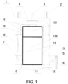
FIG. 1 is a schematic view of an internal structure of an epidemic prevention channel according to the invention. -
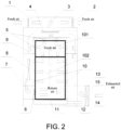
FIG. 2 is a schematic view of the movement of airflow in the epidemic prevention channel according to the invention. - 1: channel body, 2: air inlet, 3: air intake fan, 4: first filtering and sterilizing device, 5: first nozzle group, 6: air return port, 7: air return fan, 8: second filtering and sterilizing device, 9: air duct, 10: second nozzle group, 11: exhaust air inlet, 12: exhaust pipe, 13: exhaust fan, 14: third filtering and sterilizing device, 15: exhaust air outlet: 101: upper area, and 102: lower area.
- The technical solutions of the disclosure are further described in detail in combination with the accompanying drawings and embodiments.
- As shown in
FIG. 1 andFIG. 2 , the invention provides an epidemic prevention channel including achannel body 1, and thechannel body 1 is provided with an air inlet system, an air return system, and an exhaust system. An interior of thechannel body 1 is divided into anupper area 101 and alower area 102. The air inlet system includesair inlets 2, anair intake fan 3, a first filtering and sterilizingdevice 4, and afirst nozzle group 5 formed by a plurality of nozzles installed on a top wall of thechannel body 1 and side walls of theupper area 101. Theair intake fan 3 introduces external fresh air through theair inlets 2, the external fresh air passes through theair inlets 2, theair intake fan 3, the first filtering and sterilizingdevice 4, and thefirst nozzle group 5 in sequence and is then sprayed into and purifies theupper area 101 of thechannel body 1. The air return system includes anair return port 6, anair return fan 7, a second filtering and sterilizingdevice 8, and asecond nozzle group 10 formed by a plurality of nozzles installed on side walls of thelower area 102 of thechannel body 1. The air in thechannel body 1 passes through theair return port 6, theair return fan 7, the second filtering and sterilizingdevice 8, and thesecond nozzle group 10 in sequence and then circulates, is sprayed into, and purifies thelower area 102 of thechannel body 1. The exhaust system includes anexhaust air inlet 11 provided at a bottom of two ends of thechannel body 1, anexhaust pipe 12 communicating with theexhaust air inlet 11, anexhaust fan 13, a third filtering and sterilizingdevice 14, and anexhaust air outlet 15. The air in the interior of thechannel body 1 may pass through theexhaust air inlet 11, theexhaust pipe 12, theexhaust fan 13, the third filtering and sterilizingdevice 14, and theexhaust air outlet 15 in sequence and flows to the outside of the epidemic prevention channel. The exhausted air is filtered and sterilized air and thus may not lead to secondary pollution. - In a preferred embodiment, the top of the
channel body 1 is provided with an air inlet box body, theair inlets 2 are arranged at both ends of the air inlet box body, and theair intake fan 3 is located in the air inlet box body. Hollow sandwich wall layers are provided between the top wall and side walls of thechannel body 1, the sandwich wall layers include an upper layer and a lower layer. The upper layer and the lower layer are partitioned such that air cannot circulate. A top portion of the upper layer communicates with an outlet of theair intake fan 3, the upper layer also communicates with thefirst nozzle group 5, and the first filtering and sterilizingdevice 4 is arranged in the upper layer. The first filtering and sterilizingdevice 4 is connected to the outlet of theair intake fan 3. The external fresh air is pressurized by theair intake fan 3, is sterilized by the first filtering and sterilizingdevice 4, and then flows into the upper layer, and the clean air flow is sent into theupper area 101 at a high speed through thefirst nozzle group 5 communicating with the upper layer. - Preferably, the
air return port 6 is located on a side wall inside thechannel body 1, and theair return port 6 communicates with the lower layer of the sandwich wall layer through theair return fan 7. A bottom portion of the lower layer communicates with an outlet of theair return fan 7, the lower layer also communicates with thesecond nozzle group 10, and the second filtering and sterilizingdevice 8 is arranged in the lower layer. The upper layer may be provided with anair duct 9 configured to communicate with the lower layers of two sandwich wall layers on the opposite side walls. The second filtering and sterilizingdevice 8 may be connected to the outlet of theair return fan 7. Part of the air processed by the second filtering and sterilizingdevice 8 is directly sprayed into thelower area 102 through the nozzles of the side wall where it is located, and the other part flows into the lower layer of the sandwich wall layer of the other side wall through theair duct 9 and is sprayed to thelower area 102 by the nozzles installed on the side wall, forming the effect of high-speed air-to-air blowing of clean air in thelower area 102. - Both the
air intake fan 3 and theair return fan 7 are turned on. The nozzles in thefirst nozzle group 5 installed on the top wall spray from top to bottom, and the nozzles installed on the side wall of the upper area spray from opposite sides. The airflow in theupper area 101 continues to flow downwards, and the positive pressure created by the airflow from the upper area causes the return air circulation to only take place in the lower area. - An exhaust box body may be arranged at an edge of the bottom of two ends of the
channel body 1, theexhaust air inlet 11 is arranged at the exhaust box body, the exhaust box body communicates with theexhaust pipe 12, and theexhaust pipe 12 is connected to theexhaust fan 13. While the air inlet system inputs fresh air into thechannel body 1, theexhaust fan 13 leads the air to the outside of the epidemic prevention channel. By adjusting the pressure difference between the inside and outside of thechannel body 1, it is ensured that fresh air is always introduced into theupper area 101 of thechannel body 1. - In this embodiment, each of the first filtering and sterilizing
device 4, the second filtering and sterilizingdevice 8, and the third filtering and sterilizingdevice 14 is one or a combination of any two filtering and sterilizing devices such as a primary filter, a high-efficiency filter, a high-pressure sterilization filter, and an ultraviolet sterilizer, and is configured for air sterilization, disinfection, and purification. - The invention further provides an epidemic prevention method as defined in
claim 7, which is implemented through the following steps. - Each nozzle of the
first nozzle group 5 and thesecond nozzle group 10 is nozzle with adjustable spray direction, so that the direction of the ejected airflow may be adjusted freely according to the height of a person or the key purification area to ensure good disinfection, sterilization, and purification effects. After a person enters the epidemic prevention channel, the air inlet system, the air return system, and the exhaust system control the pressure difference between the air inside and outside thechannel body 1 and control the flowing speed and direction of the airflow in thechannel body 1 to form the upper and lower air areas. Thefirst nozzle group 1 of the air inlet system feeds the external fresh air processed by the first filtering and sterilizingdevice 4 into theupper area 101 of thechannel body 1, so that the air is sprayed into and purifies theupper area 101 and sterilizes the various body parts of the person at theupper area 101. Thesecond nozzle group 10 of the air return system circulates and feeds the air processed by the second filtering and sterilizingdevice 8 into thelower area 102 of thechannel body 1, so that the air is sprayed into and purifies thelower area 102 and sterilizes the various body parts of the person at thelower area 102. The person entering thechannel body 1 is sprayed and sterilized in this way. Thefirst nozzle group 5 continuously blows the air in theupper area 101 to thelower area 102 to ensure that the air inhaled by the person is the external fresh air processed by the first filtering and sterilizingdevice 4 in theupper area 101. - In the invention, the nozzles on the side walls are arranged opposite to each other to ensure the air-to-air blowing effect.
- The height of the epidemic prevention channel is determined according to the height of the user. For example, when the epidemic prevention channel is to be used by adults, the internal height of the channel body is 1.9 meters, and when the epidemic prevention channel is to be used by children, the height of the channel body is 1.6 meters. As for other usage scenarios, the height may be adjusted according to needs. The height of the
upper area 101 may be ≥ 2/5 of the height of the interior of thechannel body 1, such that the body part above the armpit of the person inside thechannel body 1 is allowed to be located in theupper area 101. - The above embodiments do not limit the protection scope of the invention, and the embodiments of the invention are not limited thereto. The protection scope of the invention is defined in the appended claims.
Claims (8)
- An epidemic prevention channel, characterized in that: comprising a channel body (1), the channel body (1) is provided with an air inlet system, an air return system, and an exhaust system, an interior of the channel body (1) is divided into an upper area (101) and a lower area (102), the air inlet system comprises air inlets (2), an air intake fan (3), a first filtering and sterilizing device (4), and a first nozzle group (5) formed by a plurality of nozzles installed on a top wall of the channel body (1) and side walls of the upper area (101), the air intake fan (3) introduces external fresh air through the air inlets (2), the external fresh air passes through the air inlets (2), the air intake fan (3), the first filtering and sterilizing device (4), and the first nozzle group (5) in sequence and is sprayed into and purifies the upper area (101) of the channel body (1), the air return system comprises an air return port (6), an air return fan (7), a second filtering and sterilizing device (8), and a second nozzle group (10) formed by a plurality of nozzles installed on side walls of the lower area (102) of the channel body (1) and, an air in the channel body (1) passes through the air return port (6), the air return fan (7), the second filtering and sterilizing device (8), and the second nozzle group (10) in sequence and circulates, is sprayed into, and purifies the lower area (102) of the channel body (1), the exhaust system comprises an exhaust air inlet (11) provided at a bottom of two ends of the channel body (1), an exhaust pipe (12) communicating with the exhaust air inlet (11), an exhaust fan (13), a third filtering and sterilizing device (14), and an exhaust air outlet (15), and the air discharged from the interior of the channel body (1) passes through the exhaust air inlet (11), the exhaust pipe (12), the exhaust fan (13), the third filtering and sterilizing device (14), and the exhaust air outlet (15) in sequence and flows to the outside of the epidemic prevention channel.
- The epidemic prevention channel according to claim 1, characterized in that: hollow sandwich wall layers are provided between the top wall and side walls of the channel body (1), the sandwich wall layers comprise an upper layer and a lower layer, the upper layer and the lower layer are partitioned such that air cannot circulate, a top portion of the upper layer communicates with an outlet of the air intake fan (3), the upper layer also communicates with the first nozzle group (5), the first filtering and sterilizing device (4) is arranged in the upper layer, a bottom portion of the lower layer communicates with an outlet of the air return fan (7), the lower layer also communicates with the second nozzle group (10), the second filtering and sterilizing device (8) is arranged in the lower layer, and the upper layer is provided with an air duct (9) configured to communicate with the lower layers of two sandwich wall layers on the opposite side walls.
- The epidemic prevention channel according to claim 2, characterized in that: the top of the channel body (1) is provided with an air inlet box body, the air inlets (2) are arranged at both ends of the air inlet box body, and the air intake fan (3) is located in the air inlet box body.
- The epidemic prevention channel according to claim 3, characterized in that: the air return port (6) is located on a side wall inside the channel body (1), and the air return port (6) communicates with the lower layer of the sandwich wall layers through the air return fan (7).
- The epidemic prevention channel according to claim 4, characterized in that: an exhaust box body is arranged at an edge of the bottom of the two ends of the channel body (1), the exhaust air inlet (11) is arranged at the exhaust box body, the exhaust box body communicates with the exhaust pipe (12), and the exhaust pipe (12) is connected to the exhaust fan (13).
- The epidemic prevention channel according to claim 5, characterized in that: each of the first filtering and sterilizing device (4), the second filtering and sterilizing device (8), and the third filtering and sterilizing device (14) is one or a combination of any two filtering and sterilizing devices such as a primary filter, a high-efficiency filter, a high-pressure sterilization filter, and an ultraviolet sterilizer, and is configured for air sterilization, disinfection, and purification.
- An epidemic prevention method using the epidemic prevention channel according to any one of claims 1 to 6, characterized in that: each nozzle of the first nozzle group (5) and the second nozzle group (10) is nozzle with adjustable spraying direction, controlling, through the air inlet system, the air return system, and the exhaust system, a pressure difference between the air inside and outside the channel body and controlling a flowing speed and direction of an airflow in the channel body to form the upper and lower air areas; feeding, through the first nozzle group (5) of the air inlet system, the external fresh air processed by the first filtering and sterilizing device (4) into the upper area (101) of the channel body (1), circulating and feeding, through the second nozzle group (10) of the air return system, the air processed by the second filtering and sterilizing device (8) into the lower area (102) of the channel body (1), spraying and sterilizing a personnel entering the channel body (1); and continuously blowing, by the first nozzle group (5), the air in the upper area (101) to the lower area (102) to ensure that an air inhaled by a person is the external fresh air processed by the first filtering and sterilizing device (4) in the upper area (101).
- The epidemic prevention method according to claim 7, characterized in that: a height of the upper area (101) is ≥ 2/5 of a height of the interior of the channel body (1), such that a body part above an armpit of the person inside the channel body (1) is allowed to be located in the upper area (101).
Applications Claiming Priority (2)
| Application Number | Priority Date | Filing Date | Title |
|---|---|---|---|
| CN202010112703.9A CN111317839B (en) | 2020-02-24 | 2020-02-24 | An epidemic prevention channel and an epidemic prevention method |
| PCT/CN2020/106698 WO2021169179A1 (en) | 2020-02-24 | 2020-08-04 | Epidemic prevention channel and epidemic prevention method |
Publications (3)
| Publication Number | Publication Date |
|---|---|
| EP4112087A1 EP4112087A1 (en) | 2023-01-04 |
| EP4112087A4 EP4112087A4 (en) | 2024-04-03 |
| EP4112087B1 true EP4112087B1 (en) | 2024-11-13 |
Family
ID=71167104
Family Applications (1)
| Application Number | Title | Priority Date | Filing Date |
|---|---|---|---|
| EP20921680.3A Active EP4112087B1 (en) | 2020-02-24 | 2020-08-04 | Epidemic prevention channel and epidemic prevention method |
Country Status (3)
| Country | Link |
|---|---|
| EP (1) | EP4112087B1 (en) |
| CN (1) | CN111317839B (en) |
| WO (1) | WO2021169179A1 (en) |
Families Citing this family (9)
| Publication number | Priority date | Publication date | Assignee | Title |
|---|---|---|---|---|
| CN111317839B (en) * | 2020-02-24 | 2025-06-20 | 广东省建筑科学研究院集团股份有限公司 | An epidemic prevention channel and an epidemic prevention method |
| CN112675343A (en) * | 2020-10-23 | 2021-04-20 | 德清至珩自动化科技有限公司 | Disinfection and sterilization passing system |
| CN112731550A (en) * | 2020-12-15 | 2021-04-30 | 中国铁路设计集团有限公司 | Security door with sweep and disinfection function |
| CN112755214A (en) * | 2021-01-22 | 2021-05-07 | 上海食安天天科技有限公司 | Personnel disinfection system and disinfection method |
| CN113280435B (en) * | 2021-06-03 | 2022-07-29 | 山东博思生物技术有限公司 | Local pollution-free positive pressure isolation system |
| CN114061236B (en) * | 2021-10-08 | 2022-08-02 | 华南农业大学 | Refrigerated vehicle epidemic prevention system and method utilizing heat of engine exhaust manifold |
| CN113932327A (en) * | 2021-11-18 | 2022-01-14 | 深圳市今典建筑科技有限公司 | Novel central air conditioner and air treatment system for building epidemic prevention |
| CN114541860A (en) * | 2022-03-04 | 2022-05-27 | 无锡联盾特种防护有限公司 | An epidemic prevention tent with sterilization and disinfection effect |
| CN115968177A (en) * | 2023-01-19 | 2023-04-14 | 北京理工大学 | Medical data storage system |
Family Cites Families (20)
| Publication number | Priority date | Publication date | Assignee | Title |
|---|---|---|---|---|
| KR970007648B1 (en) * | 1994-05-09 | 1997-05-15 | 삼성전자 주식회사 | Apparatus of air shower for clean-room |
| CN2628048Y (en) * | 2003-06-27 | 2004-07-28 | 辽宁省医疗器械研究所 | Ultraviolet wind bathing sterilizing equipment |
| JP3757976B2 (en) * | 2004-04-15 | 2006-03-22 | ダイキン工業株式会社 | Heat exchange unit |
| JP4741828B2 (en) * | 2004-10-27 | 2011-08-10 | 積水化学工業株式会社 | Life odor deodorization system |
| EP1917044B1 (en) * | 2005-09-01 | 2013-05-15 | Megair Ltd. | Method and apparatus for treating biologically contaminated air |
| IT1391328B1 (en) * | 2008-08-08 | 2011-12-05 | Nm Tech Ltd Nanomaterials And Microdevices Technology | EQUIPMENT FOR AIR DECONTAMINATION |
| KR101222637B1 (en) * | 2011-04-05 | 2013-01-16 | 에너바이오텍(주) | Movable disinfection and sterilization apparatus |
| CA2835731C (en) * | 2011-07-12 | 2014-07-08 | Ruks Engineering Ltd. | Real-time gas monitoring method and system |
| JP2014066467A (en) * | 2012-09-27 | 2014-04-17 | Sanpo Denki Kk | Air shower device |
| CN203036779U (en) * | 2013-01-24 | 2013-07-03 | 上海富贯智能科技有限公司 | Purifying air-conditioning system for operating room |
| EP3268056A4 (en) * | 2015-03-09 | 2018-12-05 | Bluezone IP Holding LLC | Air cleaning apparatus and method for container |
| KR101676582B1 (en) * | 2015-11-16 | 2016-11-17 | 신용기 | Wind shower device |
| CN205664524U (en) * | 2016-06-01 | 2016-10-26 | 广州蓝净环保科技发展有限公司 | Clean operating room air conditioning system |
| CN207350579U (en) * | 2017-03-15 | 2018-05-11 | 广州安捷生物安全科技股份有限公司 | Assembled intelligent isolation ward |
| KR101973931B1 (en) * | 2017-04-18 | 2019-08-23 | 김성규 | Front door cleaning system for preventing inflow of fine dust and virus and Drive Method of the Same |
| CN207057174U (en) * | 2017-07-14 | 2018-03-02 | 江苏益力达生物科技有限公司 | A kind of toilet |
| CN208832610U (en) * | 2018-08-07 | 2019-05-07 | 四川医小二医疗器械有限公司 | It is a kind of epidemic prevention, ten thousand grades of energy-efficient animal surgery room clean by laminar flow system |
| CN209944597U (en) * | 2019-03-13 | 2020-01-14 | 苏州净化工程安装有限公司 | Operating room clean system |
| CN111317839B (en) * | 2020-02-24 | 2025-06-20 | 广东省建筑科学研究院集团股份有限公司 | An epidemic prevention channel and an epidemic prevention method |
| CN212730481U (en) * | 2020-02-24 | 2021-03-19 | 广东省建筑科学研究院集团股份有限公司 | Epidemic prevention channel |
-
2020
- 2020-02-24 CN CN202010112703.9A patent/CN111317839B/en active Active
- 2020-08-04 EP EP20921680.3A patent/EP4112087B1/en active Active
- 2020-08-04 WO PCT/CN2020/106698 patent/WO2021169179A1/en not_active Ceased
Also Published As
| Publication number | Publication date |
|---|---|
| EP4112087A1 (en) | 2023-01-04 |
| EP4112087A4 (en) | 2024-04-03 |
| CN111317839B (en) | 2025-06-20 |
| CN111317839A (en) | 2020-06-23 |
| WO2021169179A1 (en) | 2021-09-02 |
Similar Documents
| Publication | Publication Date | Title |
|---|---|---|
| EP4112087A1 (en) | Epidemic prevention channel and epidemic prevention method | |
| CN111486529B (en) | A kind of air directional transmission device and air sterilization system in pathogenic microorganism prevention and control ward area | |
| CN111627140A (en) | Intelligent epidemic prevention channel | |
| JP5155358B2 (en) | Pathogen infection prevention system and method | |
| WO2019227829A1 (en) | Protective device for isolation | |
| CN213687164U (en) | Intelligent epidemic prevention channel with security and protection function | |
| CN214094814U (en) | Epidemic prevention system for preventing air infection in closed space | |
| WO2019227830A1 (en) | Air curtain system and protective isolation device | |
| CN108669809A (en) | A kind of half isolation diagnostic table | |
| CN111473437A (en) | Negative pressure isolation ward | |
| CN111854029A (en) | Sickbed cleaning device with aerosol directional control function and control method | |
| CN111409419B (en) | Negative pressure device and ambulance | |
| CN213020128U (en) | Sickbed cleaning device with aerosol directional control function | |
| CN111388894A (en) | Infectious disease patient respiratory discharge pathogen collecting, inactivating and auxiliary breathing equipment | |
| WO2021179868A1 (en) | Protection device and device against harmful bacteria and viruses in densely populated area | |
| CN212009676U (en) | An intelligent anti-epidemic channel | |
| CN212730481U (en) | Epidemic prevention channel | |
| CN111981621A (en) | Brand-new wind direct current epidemic prevention passageway | |
| CN212746788U (en) | Brand-new wind direct current epidemic prevention passageway | |
| CN201322392Y (en) | Individualized ventilating device capable of interrupting transmission of air with infectious germs | |
| CN212179092U (en) | Central air conditioning bacterium virus centralized killing system | |
| CN112370564A (en) | Intelligent epidemic prevention channel with transition region | |
| CN2628048Y (en) | Ultraviolet wind bathing sterilizing equipment | |
| CN215652857U (en) | Intelligent epidemic prevention channel with transition region | |
| CN112665096B (en) | A kind of ventilation method of central air-conditioning system |
Legal Events
| Date | Code | Title | Description |
|---|---|---|---|
| STAA | Information on the status of an ep patent application or granted ep patent |
Free format text: STATUS: THE INTERNATIONAL PUBLICATION HAS BEEN MADE |
|
| PUAI | Public reference made under article 153(3) epc to a published international application that has entered the european phase |
Free format text: ORIGINAL CODE: 0009012 |
|
| STAA | Information on the status of an ep patent application or granted ep patent |
Free format text: STATUS: REQUEST FOR EXAMINATION WAS MADE |
|
| 17P | Request for examination filed |
Effective date: 20220429 |
|
| AK | Designated contracting states |
Kind code of ref document: A1 Designated state(s): AL AT BE BG CH CY CZ DE DK EE ES FI FR GB GR HR HU IE IS IT LI LT LU LV MC MK MT NL NO PL PT RO RS SE SI SK SM TR |
|
| DAV | Request for validation of the european patent (deleted) | ||
| DAX | Request for extension of the european patent (deleted) | ||
| REG | Reference to a national code |
Ref country code: DE Ref legal event code: R079 Free format text: PREVIOUS MAIN CLASS: A61L0009000000 Ipc: F24F0008200000 Ref document number: 602020041493 Country of ref document: DE |
|
| A4 | Supplementary search report drawn up and despatched |
Effective date: 20240301 |
|
| RIC1 | Information provided on ipc code assigned before grant |
Ipc: F24F 8/133 20210101ALI20240226BHEP Ipc: F24F 11/00 20180101ALI20240226BHEP Ipc: A61L 9/20 20060101ALI20240226BHEP Ipc: A61L 9/14 20060101ALI20240226BHEP Ipc: F24F 8/22 20210101ALI20240226BHEP Ipc: F24F 8/10 20210101ALI20240226BHEP Ipc: F24F 8/20 20210101AFI20240226BHEP |
|
| GRAP | Despatch of communication of intention to grant a patent |
Free format text: ORIGINAL CODE: EPIDOSNIGR1 |
|
| STAA | Information on the status of an ep patent application or granted ep patent |
Free format text: STATUS: GRANT OF PATENT IS INTENDED |
|
| RIC1 | Information provided on ipc code assigned before grant |
Ipc: F24F 8/133 20210101ALI20240702BHEP Ipc: F24F 11/00 20180101ALI20240702BHEP Ipc: A61L 9/20 20060101ALI20240702BHEP Ipc: A61L 9/14 20060101ALI20240702BHEP Ipc: F24F 8/22 20210101ALI20240702BHEP Ipc: F24F 8/10 20210101ALI20240702BHEP Ipc: F24F 8/20 20210101AFI20240702BHEP |
|
| INTG | Intention to grant announced |
Effective date: 20240723 |
|
| P01 | Opt-out of the competence of the unified patent court (upc) registered |
Free format text: CASE NUMBER: APP_46959/2024 Effective date: 20240814 |
|
| GRAS | Grant fee paid |
Free format text: ORIGINAL CODE: EPIDOSNIGR3 |
|
| GRAA | (expected) grant |
Free format text: ORIGINAL CODE: 0009210 |
|
| STAA | Information on the status of an ep patent application or granted ep patent |
Free format text: STATUS: THE PATENT HAS BEEN GRANTED |
|
| AK | Designated contracting states |
Kind code of ref document: B1 Designated state(s): AL AT BE BG CH CY CZ DE DK EE ES FI FR GB GR HR HU IE IS IT LI LT LU LV MC MK MT NL NO PL PT RO RS SE SI SK SM TR |
|
| REG | Reference to a national code |
Ref country code: GB Ref legal event code: FG4D |
|
| REG | Reference to a national code |
Ref country code: CH Ref legal event code: EP |
|
| REG | Reference to a national code |
Ref country code: IE Ref legal event code: FG4D |
|
| REG | Reference to a national code |
Ref country code: DE Ref legal event code: R096 Ref document number: 602020041493 Country of ref document: DE |
|
| REG | Reference to a national code |
Ref country code: LT Ref legal event code: MG9D |
|
| REG | Reference to a national code |
Ref country code: NL Ref legal event code: MP Effective date: 20241113 |
|
| PG25 | Lapsed in a contracting state [announced via postgrant information from national office to epo] |
Ref country code: HR Free format text: LAPSE BECAUSE OF FAILURE TO SUBMIT A TRANSLATION OF THE DESCRIPTION OR TO PAY THE FEE WITHIN THE PRESCRIBED TIME-LIMIT Effective date: 20241113 Ref country code: PT Free format text: LAPSE BECAUSE OF FAILURE TO SUBMIT A TRANSLATION OF THE DESCRIPTION OR TO PAY THE FEE WITHIN THE PRESCRIBED TIME-LIMIT Effective date: 20250313 Ref country code: IS Free format text: LAPSE BECAUSE OF FAILURE TO SUBMIT A TRANSLATION OF THE DESCRIPTION OR TO PAY THE FEE WITHIN THE PRESCRIBED TIME-LIMIT Effective date: 20250313 |
|
| PG25 | Lapsed in a contracting state [announced via postgrant information from national office to epo] |
Ref country code: FI Free format text: LAPSE BECAUSE OF FAILURE TO SUBMIT A TRANSLATION OF THE DESCRIPTION OR TO PAY THE FEE WITHIN THE PRESCRIBED TIME-LIMIT Effective date: 20241113 Ref country code: NL Free format text: LAPSE BECAUSE OF FAILURE TO SUBMIT A TRANSLATION OF THE DESCRIPTION OR TO PAY THE FEE WITHIN THE PRESCRIBED TIME-LIMIT Effective date: 20241113 |
|
| REG | Reference to a national code |
Ref country code: AT Ref legal event code: MK05 Ref document number: 1741942 Country of ref document: AT Kind code of ref document: T Effective date: 20241113 |
|
| PG25 | Lapsed in a contracting state [announced via postgrant information from national office to epo] |
Ref country code: BG Free format text: LAPSE BECAUSE OF FAILURE TO SUBMIT A TRANSLATION OF THE DESCRIPTION OR TO PAY THE FEE WITHIN THE PRESCRIBED TIME-LIMIT Effective date: 20241113 |
|
| PG25 | Lapsed in a contracting state [announced via postgrant information from national office to epo] |
Ref country code: ES Free format text: LAPSE BECAUSE OF FAILURE TO SUBMIT A TRANSLATION OF THE DESCRIPTION OR TO PAY THE FEE WITHIN THE PRESCRIBED TIME-LIMIT Effective date: 20241113 |
|
| PG25 | Lapsed in a contracting state [announced via postgrant information from national office to epo] |
Ref country code: NO Free format text: LAPSE BECAUSE OF FAILURE TO SUBMIT A TRANSLATION OF THE DESCRIPTION OR TO PAY THE FEE WITHIN THE PRESCRIBED TIME-LIMIT Effective date: 20250213 |
|
| PG25 | Lapsed in a contracting state [announced via postgrant information from national office to epo] |
Ref country code: GR Free format text: LAPSE BECAUSE OF FAILURE TO SUBMIT A TRANSLATION OF THE DESCRIPTION OR TO PAY THE FEE WITHIN THE PRESCRIBED TIME-LIMIT Effective date: 20250214 Ref country code: LV Free format text: LAPSE BECAUSE OF FAILURE TO SUBMIT A TRANSLATION OF THE DESCRIPTION OR TO PAY THE FEE WITHIN THE PRESCRIBED TIME-LIMIT Effective date: 20241113 Ref country code: AT Free format text: LAPSE BECAUSE OF FAILURE TO SUBMIT A TRANSLATION OF THE DESCRIPTION OR TO PAY THE FEE WITHIN THE PRESCRIBED TIME-LIMIT Effective date: 20241113 |
|
| PG25 | Lapsed in a contracting state [announced via postgrant information from national office to epo] |
Ref country code: PL Free format text: LAPSE BECAUSE OF FAILURE TO SUBMIT A TRANSLATION OF THE DESCRIPTION OR TO PAY THE FEE WITHIN THE PRESCRIBED TIME-LIMIT Effective date: 20241113 |
|
| PG25 | Lapsed in a contracting state [announced via postgrant information from national office to epo] |
Ref country code: RS Free format text: LAPSE BECAUSE OF FAILURE TO SUBMIT A TRANSLATION OF THE DESCRIPTION OR TO PAY THE FEE WITHIN THE PRESCRIBED TIME-LIMIT Effective date: 20250213 |
|
| PG25 | Lapsed in a contracting state [announced via postgrant information from national office to epo] |
Ref country code: SM Free format text: LAPSE BECAUSE OF FAILURE TO SUBMIT A TRANSLATION OF THE DESCRIPTION OR TO PAY THE FEE WITHIN THE PRESCRIBED TIME-LIMIT Effective date: 20241113 |
|
| PG25 | Lapsed in a contracting state [announced via postgrant information from national office to epo] |
Ref country code: DK Free format text: LAPSE BECAUSE OF FAILURE TO SUBMIT A TRANSLATION OF THE DESCRIPTION OR TO PAY THE FEE WITHIN THE PRESCRIBED TIME-LIMIT Effective date: 20241113 |
|
| PG25 | Lapsed in a contracting state [announced via postgrant information from national office to epo] |
Ref country code: EE Free format text: LAPSE BECAUSE OF FAILURE TO SUBMIT A TRANSLATION OF THE DESCRIPTION OR TO PAY THE FEE WITHIN THE PRESCRIBED TIME-LIMIT Effective date: 20241113 |
|
| PG25 | Lapsed in a contracting state [announced via postgrant information from national office to epo] |
Ref country code: RO Free format text: LAPSE BECAUSE OF FAILURE TO SUBMIT A TRANSLATION OF THE DESCRIPTION OR TO PAY THE FEE WITHIN THE PRESCRIBED TIME-LIMIT Effective date: 20241113 |
|
| PG25 | Lapsed in a contracting state [announced via postgrant information from national office to epo] |
Ref country code: SK Free format text: LAPSE BECAUSE OF FAILURE TO SUBMIT A TRANSLATION OF THE DESCRIPTION OR TO PAY THE FEE WITHIN THE PRESCRIBED TIME-LIMIT Effective date: 20241113 |
|
| PG25 | Lapsed in a contracting state [announced via postgrant information from national office to epo] |
Ref country code: CZ Free format text: LAPSE BECAUSE OF FAILURE TO SUBMIT A TRANSLATION OF THE DESCRIPTION OR TO PAY THE FEE WITHIN THE PRESCRIBED TIME-LIMIT Effective date: 20241113 |
|
| PG25 | Lapsed in a contracting state [announced via postgrant information from national office to epo] |
Ref country code: IT Free format text: LAPSE BECAUSE OF FAILURE TO SUBMIT A TRANSLATION OF THE DESCRIPTION OR TO PAY THE FEE WITHIN THE PRESCRIBED TIME-LIMIT Effective date: 20241113 |
|
| REG | Reference to a national code |
Ref country code: DE Ref legal event code: R097 Ref document number: 602020041493 Country of ref document: DE |
|
| PG25 | Lapsed in a contracting state [announced via postgrant information from national office to epo] |
Ref country code: SE Free format text: LAPSE BECAUSE OF FAILURE TO SUBMIT A TRANSLATION OF THE DESCRIPTION OR TO PAY THE FEE WITHIN THE PRESCRIBED TIME-LIMIT Effective date: 20241113 |
|
| PLBE | No opposition filed within time limit |
Free format text: ORIGINAL CODE: 0009261 |
|
| STAA | Information on the status of an ep patent application or granted ep patent |
Free format text: STATUS: NO OPPOSITION FILED WITHIN TIME LIMIT |
|
| 26N | No opposition filed |
Effective date: 20250814 |
|
| REG | Reference to a national code |
Ref country code: DE Ref legal event code: R119 Ref document number: 602020041493 Country of ref document: DE |
|
| REG | Reference to a national code |
Ref country code: CH Ref legal event code: H13 Free format text: ST27 STATUS EVENT CODE: U-0-0-H10-H13 (AS PROVIDED BY THE NATIONAL OFFICE) Effective date: 20260324 |
|
| PG25 | Lapsed in a contracting state [announced via postgrant information from national office to epo] |
Ref country code: MC Free format text: LAPSE BECAUSE OF FAILURE TO SUBMIT A TRANSLATION OF THE DESCRIPTION OR TO PAY THE FEE WITHIN THE PRESCRIBED TIME-LIMIT Effective date: 20241113 |
|
| PG25 | Lapsed in a contracting state [announced via postgrant information from national office to epo] |
Ref country code: LU Free format text: LAPSE BECAUSE OF NON-PAYMENT OF DUE FEES Effective date: 20250804 |
|
| PG25 | Lapsed in a contracting state [announced via postgrant information from national office to epo] |
Ref country code: CH Free format text: LAPSE BECAUSE OF NON-PAYMENT OF DUE FEES Effective date: 20250831 |
|
| GBPC | Gb: european patent ceased through non-payment of renewal fee |
Effective date: 20250804 |