EP4111996B1 - Systeme und verfahren zum verwenden der dreidimensionalen bildrekonstruktion als hilfe beim beurteilen von knochen- oder weichteilaberrationen in der orthopädischen chirurgie - Google Patents
Systeme und verfahren zum verwenden der dreidimensionalen bildrekonstruktion als hilfe beim beurteilen von knochen- oder weichteilaberrationen in der orthopädischen chirurgie Download PDFInfo
- Publication number
- EP4111996B1 EP4111996B1 EP22182089.7A EP22182089A EP4111996B1 EP 4111996 B1 EP4111996 B1 EP 4111996B1 EP 22182089 A EP22182089 A EP 22182089A EP 4111996 B1 EP4111996 B1 EP 4111996B1
- Authority
- EP
- European Patent Office
- Prior art keywords
- bone
- aberration
- model
- image
- orthopedic element
- Prior art date
- Legal status (The legal status is an assumption and is not a legal conclusion. Google has not performed a legal analysis and makes no representation as to the accuracy of the status listed.)
- Active
Links
Images






Classifications
-
- G—PHYSICS
- G06—COMPUTING OR CALCULATING; COUNTING
- G06T—IMAGE DATA PROCESSING OR GENERATION, IN GENERAL
- G06T19/00—Manipulating three-dimensional [3D] models or images for computer graphics
- G06T19/20—Editing of three-dimensional [3D] images, e.g. changing shapes or colours, aligning objects or positioning parts
-
- A—HUMAN NECESSITIES
- A61—MEDICAL OR VETERINARY SCIENCE; HYGIENE
- A61B—DIAGNOSIS; SURGERY; IDENTIFICATION
- A61B34/00—Computer-aided surgery; Manipulators or robots specially adapted for use in surgery
- A61B34/10—Computer-aided planning, simulation or modelling of surgical operations
-
- A—HUMAN NECESSITIES
- A61—MEDICAL OR VETERINARY SCIENCE; HYGIENE
- A61B—DIAGNOSIS; SURGERY; IDENTIFICATION
- A61B6/00—Apparatus or devices for radiation diagnosis; Apparatus or devices for radiation diagnosis combined with radiation therapy equipment
- A61B6/46—Arrangements for interfacing with the operator or the patient
- A61B6/461—Displaying means of special interest
- A61B6/466—Displaying means of special interest adapted to display 3D data
-
- A—HUMAN NECESSITIES
- A61—MEDICAL OR VETERINARY SCIENCE; HYGIENE
- A61B—DIAGNOSIS; SURGERY; IDENTIFICATION
- A61B6/00—Apparatus or devices for radiation diagnosis; Apparatus or devices for radiation diagnosis combined with radiation therapy equipment
- A61B6/50—Apparatus or devices for radiation diagnosis; Apparatus or devices for radiation diagnosis combined with radiation therapy equipment specially adapted for specific body parts; specially adapted for specific clinical applications
- A61B6/505—Apparatus or devices for radiation diagnosis; Apparatus or devices for radiation diagnosis combined with radiation therapy equipment specially adapted for specific body parts; specially adapted for specific clinical applications for diagnosis of bone
-
- A—HUMAN NECESSITIES
- A61—MEDICAL OR VETERINARY SCIENCE; HYGIENE
- A61B—DIAGNOSIS; SURGERY; IDENTIFICATION
- A61B6/00—Apparatus or devices for radiation diagnosis; Apparatus or devices for radiation diagnosis combined with radiation therapy equipment
- A61B6/58—Testing, adjusting or calibrating thereof
- A61B6/582—Calibration
-
- A—HUMAN NECESSITIES
- A61—MEDICAL OR VETERINARY SCIENCE; HYGIENE
- A61B—DIAGNOSIS; SURGERY; IDENTIFICATION
- A61B90/00—Instruments, implements or accessories specially adapted for surgery or diagnosis and not covered by any of the groups A61B1/00 - A61B50/00, e.g. for luxation treatment or for protecting wound edges
- A61B90/36—Image-producing devices or illumination devices not otherwise provided for
-
- A—HUMAN NECESSITIES
- A61—MEDICAL OR VETERINARY SCIENCE; HYGIENE
- A61B—DIAGNOSIS; SURGERY; IDENTIFICATION
- A61B90/00—Instruments, implements or accessories specially adapted for surgery or diagnosis and not covered by any of the groups A61B1/00 - A61B50/00, e.g. for luxation treatment or for protecting wound edges
- A61B90/36—Image-producing devices or illumination devices not otherwise provided for
- A61B90/37—Surgical systems with images on a monitor during operation
-
- A—HUMAN NECESSITIES
- A61—MEDICAL OR VETERINARY SCIENCE; HYGIENE
- A61F—FILTERS IMPLANTABLE INTO BLOOD VESSELS; PROSTHESES; DEVICES PROVIDING PATENCY TO, OR PREVENTING COLLAPSING OF, TUBULAR STRUCTURES OF THE BODY, e.g. STENTS; ORTHOPAEDIC, NURSING OR CONTRACEPTIVE DEVICES; FOMENTATION; TREATMENT OR PROTECTION OF EYES OR EARS; BANDAGES, DRESSINGS OR ABSORBENT PADS; FIRST-AID KITS
- A61F2/00—Filters implantable into blood vessels; Prostheses, i.e. artificial substitutes or replacements for parts of the body; Appliances for connecting them with the body; Devices providing patency to, or preventing collapsing of, tubular structures of the body, e.g. stents
- A61F2/02—Prostheses implantable into the body
- A61F2/30—Joints
- A61F2/32—Joints for the hip
- A61F2/36—Femoral heads ; Femoral endoprostheses
- A61F2/3609—Femoral heads or necks; Connections of endoprosthetic heads or necks to endoprosthetic femoral shafts
-
- A—HUMAN NECESSITIES
- A61—MEDICAL OR VETERINARY SCIENCE; HYGIENE
- A61F—FILTERS IMPLANTABLE INTO BLOOD VESSELS; PROSTHESES; DEVICES PROVIDING PATENCY TO, OR PREVENTING COLLAPSING OF, TUBULAR STRUCTURES OF THE BODY, e.g. STENTS; ORTHOPAEDIC, NURSING OR CONTRACEPTIVE DEVICES; FOMENTATION; TREATMENT OR PROTECTION OF EYES OR EARS; BANDAGES, DRESSINGS OR ABSORBENT PADS; FIRST-AID KITS
- A61F2/00—Filters implantable into blood vessels; Prostheses, i.e. artificial substitutes or replacements for parts of the body; Appliances for connecting them with the body; Devices providing patency to, or preventing collapsing of, tubular structures of the body, e.g. stents
- A61F2/02—Prostheses implantable into the body
- A61F2/30—Joints
- A61F2/46—Special tools for implanting artificial joints
- A61F2/468—Testing instruments for artificial joints
-
- B—PERFORMING OPERATIONS; TRANSPORTING
- B29—WORKING OF PLASTICS; WORKING OF SUBSTANCES IN A PLASTIC STATE IN GENERAL
- B29C—SHAPING OR JOINING OF PLASTICS; SHAPING OF MATERIAL IN A PLASTIC STATE, NOT OTHERWISE PROVIDED FOR; AFTER-TREATMENT OF THE SHAPED PRODUCTS, e.g. REPAIRING
- B29C64/00—Additive manufacturing, i.e. manufacturing of three-dimensional [3D] objects by additive deposition, additive agglomeration or additive layering, e.g. by 3D printing, stereolithography or selective laser sintering
- B29C64/30—Auxiliary operations or equipment
- B29C64/386—Data acquisition or data processing for additive manufacturing
-
- B—PERFORMING OPERATIONS; TRANSPORTING
- B33—ADDITIVE MANUFACTURING TECHNOLOGY
- B33Y—ADDITIVE MANUFACTURING, i.e. MANUFACTURING OF THREE-DIMENSIONAL [3D] OBJECTS BY ADDITIVE DEPOSITION, ADDITIVE AGGLOMERATION OR ADDITIVE LAYERING, e.g. BY 3D PRINTING, STEREOLITHOGRAPHY OR SELECTIVE LASER SINTERING
- B33Y30/00—Apparatus for additive manufacturing; Details thereof or accessories therefor
-
- B—PERFORMING OPERATIONS; TRANSPORTING
- B33—ADDITIVE MANUFACTURING TECHNOLOGY
- B33Y—ADDITIVE MANUFACTURING, i.e. MANUFACTURING OF THREE-DIMENSIONAL [3D] OBJECTS BY ADDITIVE DEPOSITION, ADDITIVE AGGLOMERATION OR ADDITIVE LAYERING, e.g. BY 3D PRINTING, STEREOLITHOGRAPHY OR SELECTIVE LASER SINTERING
- B33Y50/00—Data acquisition or data processing for additive manufacturing
-
- B—PERFORMING OPERATIONS; TRANSPORTING
- B33—ADDITIVE MANUFACTURING TECHNOLOGY
- B33Y—ADDITIVE MANUFACTURING, i.e. MANUFACTURING OF THREE-DIMENSIONAL [3D] OBJECTS BY ADDITIVE DEPOSITION, ADDITIVE AGGLOMERATION OR ADDITIVE LAYERING, e.g. BY 3D PRINTING, STEREOLITHOGRAPHY OR SELECTIVE LASER SINTERING
- B33Y80/00—Products made by additive manufacturing
-
- G—PHYSICS
- G06—COMPUTING OR CALCULATING; COUNTING
- G06F—ELECTRIC DIGITAL DATA PROCESSING
- G06F3/00—Input arrangements for transferring data to be processed into a form capable of being handled by the computer; Output arrangements for transferring data from processing unit to output unit, e.g. interface arrangements
- G06F3/01—Input arrangements or combined input and output arrangements for interaction between user and computer
- G06F3/011—Arrangements for interaction with the human body, e.g. for user immersion in virtual reality
-
- G—PHYSICS
- G06—COMPUTING OR CALCULATING; COUNTING
- G06N—COMPUTING ARRANGEMENTS BASED ON SPECIFIC COMPUTATIONAL MODELS
- G06N3/00—Computing arrangements based on biological models
- G06N3/02—Neural networks
- G06N3/04—Architecture, e.g. interconnection topology
- G06N3/0464—Convolutional networks [CNN, ConvNet]
-
- G—PHYSICS
- G06—COMPUTING OR CALCULATING; COUNTING
- G06T—IMAGE DATA PROCESSING OR GENERATION, IN GENERAL
- G06T12/00—Tomographic reconstruction from projections
-
- G—PHYSICS
- G06—COMPUTING OR CALCULATING; COUNTING
- G06T—IMAGE DATA PROCESSING OR GENERATION, IN GENERAL
- G06T7/00—Image analysis
- G06T7/0002—Inspection of images, e.g. flaw detection
- G06T7/0012—Biomedical image inspection
- G06T7/0014—Biomedical image inspection using an image reference approach
-
- G—PHYSICS
- G06—COMPUTING OR CALCULATING; COUNTING
- G06T—IMAGE DATA PROCESSING OR GENERATION, IN GENERAL
- G06T7/00—Image analysis
- G06T7/30—Determination of transform parameters for the alignment of images, i.e. image registration
- G06T7/33—Determination of transform parameters for the alignment of images, i.e. image registration using feature-based methods
- G06T7/337—Determination of transform parameters for the alignment of images, i.e. image registration using feature-based methods involving reference images or patches
-
- G—PHYSICS
- G06—COMPUTING OR CALCULATING; COUNTING
- G06T—IMAGE DATA PROCESSING OR GENERATION, IN GENERAL
- G06T7/00—Image analysis
- G06T7/50—Depth or shape recovery
-
- G—PHYSICS
- G06—COMPUTING OR CALCULATING; COUNTING
- G06V—IMAGE OR VIDEO RECOGNITION OR UNDERSTANDING
- G06V10/00—Arrangements for image or video recognition or understanding
- G06V10/70—Arrangements for image or video recognition or understanding using pattern recognition or machine learning
- G06V10/82—Arrangements for image or video recognition or understanding using pattern recognition or machine learning using neural networks
-
- G—PHYSICS
- G16—INFORMATION AND COMMUNICATION TECHNOLOGY [ICT] SPECIALLY ADAPTED FOR SPECIFIC APPLICATION FIELDS
- G16H—HEALTHCARE INFORMATICS, i.e. INFORMATION AND COMMUNICATION TECHNOLOGY [ICT] SPECIALLY ADAPTED FOR THE HANDLING OR PROCESSING OF MEDICAL OR HEALTHCARE DATA
- G16H30/00—ICT specially adapted for the handling or processing of medical images
- G16H30/20—ICT specially adapted for the handling or processing of medical images for handling medical images, e.g. DICOM, HL7 or PACS
-
- G—PHYSICS
- G16—INFORMATION AND COMMUNICATION TECHNOLOGY [ICT] SPECIALLY ADAPTED FOR SPECIFIC APPLICATION FIELDS
- G16H—HEALTHCARE INFORMATICS, i.e. INFORMATION AND COMMUNICATION TECHNOLOGY [ICT] SPECIALLY ADAPTED FOR THE HANDLING OR PROCESSING OF MEDICAL OR HEALTHCARE DATA
- G16H30/00—ICT specially adapted for the handling or processing of medical images
- G16H30/40—ICT specially adapted for the handling or processing of medical images for processing medical images, e.g. editing
-
- G—PHYSICS
- G16—INFORMATION AND COMMUNICATION TECHNOLOGY [ICT] SPECIALLY ADAPTED FOR SPECIFIC APPLICATION FIELDS
- G16H—HEALTHCARE INFORMATICS, i.e. INFORMATION AND COMMUNICATION TECHNOLOGY [ICT] SPECIALLY ADAPTED FOR THE HANDLING OR PROCESSING OF MEDICAL OR HEALTHCARE DATA
- G16H50/00—ICT specially adapted for medical diagnosis, medical simulation or medical data mining; ICT specially adapted for detecting, monitoring or modelling epidemics or pandemics
- G16H50/20—ICT specially adapted for medical diagnosis, medical simulation or medical data mining; ICT specially adapted for detecting, monitoring or modelling epidemics or pandemics for computer-aided diagnosis, e.g. based on medical expert systems
-
- G—PHYSICS
- G16—INFORMATION AND COMMUNICATION TECHNOLOGY [ICT] SPECIALLY ADAPTED FOR SPECIFIC APPLICATION FIELDS
- G16H—HEALTHCARE INFORMATICS, i.e. INFORMATION AND COMMUNICATION TECHNOLOGY [ICT] SPECIALLY ADAPTED FOR THE HANDLING OR PROCESSING OF MEDICAL OR HEALTHCARE DATA
- G16H50/00—ICT specially adapted for medical diagnosis, medical simulation or medical data mining; ICT specially adapted for detecting, monitoring or modelling epidemics or pandemics
- G16H50/50—ICT specially adapted for medical diagnosis, medical simulation or medical data mining; ICT specially adapted for detecting, monitoring or modelling epidemics or pandemics for simulation or modelling of medical disorders
-
- A—HUMAN NECESSITIES
- A61—MEDICAL OR VETERINARY SCIENCE; HYGIENE
- A61B—DIAGNOSIS; SURGERY; IDENTIFICATION
- A61B17/00—Surgical instruments, devices or methods
- A61B17/14—Surgical saws
- A61B17/15—Guides therefor
- A61B17/154—Guides therefor for preparing bone for knee prosthesis
- A61B17/155—Cutting femur
-
- A—HUMAN NECESSITIES
- A61—MEDICAL OR VETERINARY SCIENCE; HYGIENE
- A61B—DIAGNOSIS; SURGERY; IDENTIFICATION
- A61B34/00—Computer-aided surgery; Manipulators or robots specially adapted for use in surgery
- A61B34/10—Computer-aided planning, simulation or modelling of surgical operations
- A61B2034/101—Computer-aided simulation of surgical operations
-
- A—HUMAN NECESSITIES
- A61—MEDICAL OR VETERINARY SCIENCE; HYGIENE
- A61B—DIAGNOSIS; SURGERY; IDENTIFICATION
- A61B34/00—Computer-aided surgery; Manipulators or robots specially adapted for use in surgery
- A61B34/10—Computer-aided planning, simulation or modelling of surgical operations
- A61B2034/101—Computer-aided simulation of surgical operations
- A61B2034/105—Modelling of the patient, e.g. for ligaments or bones
-
- A—HUMAN NECESSITIES
- A61—MEDICAL OR VETERINARY SCIENCE; HYGIENE
- A61B—DIAGNOSIS; SURGERY; IDENTIFICATION
- A61B34/00—Computer-aided surgery; Manipulators or robots specially adapted for use in surgery
- A61B34/10—Computer-aided planning, simulation or modelling of surgical operations
- A61B2034/107—Visualisation of planned trajectories or target regions
-
- A—HUMAN NECESSITIES
- A61—MEDICAL OR VETERINARY SCIENCE; HYGIENE
- A61B—DIAGNOSIS; SURGERY; IDENTIFICATION
- A61B34/00—Computer-aided surgery; Manipulators or robots specially adapted for use in surgery
- A61B34/10—Computer-aided planning, simulation or modelling of surgical operations
- A61B2034/108—Computer aided selection or customisation of medical implants or cutting guides
-
- A—HUMAN NECESSITIES
- A61—MEDICAL OR VETERINARY SCIENCE; HYGIENE
- A61B—DIAGNOSIS; SURGERY; IDENTIFICATION
- A61B34/00—Computer-aided surgery; Manipulators or robots specially adapted for use in surgery
- A61B34/20—Surgical navigation systems; Devices for tracking or guiding surgical instruments, e.g. for frameless stereotaxis
- A61B2034/2046—Tracking techniques
- A61B2034/2048—Tracking techniques using an accelerometer or inertia sensor
-
- A—HUMAN NECESSITIES
- A61—MEDICAL OR VETERINARY SCIENCE; HYGIENE
- A61B—DIAGNOSIS; SURGERY; IDENTIFICATION
- A61B90/00—Instruments, implements or accessories specially adapted for surgery or diagnosis and not covered by any of the groups A61B1/00 - A61B50/00, e.g. for luxation treatment or for protecting wound edges
- A61B90/36—Image-producing devices or illumination devices not otherwise provided for
- A61B2090/364—Correlation of different images or relation of image positions in respect to the body
- A61B2090/365—Correlation of different images or relation of image positions in respect to the body augmented reality, i.e. correlating a live optical image with another image
-
- A—HUMAN NECESSITIES
- A61—MEDICAL OR VETERINARY SCIENCE; HYGIENE
- A61B—DIAGNOSIS; SURGERY; IDENTIFICATION
- A61B90/00—Instruments, implements or accessories specially adapted for surgery or diagnosis and not covered by any of the groups A61B1/00 - A61B50/00, e.g. for luxation treatment or for protecting wound edges
- A61B90/36—Image-producing devices or illumination devices not otherwise provided for
- A61B2090/364—Correlation of different images or relation of image positions in respect to the body
- A61B2090/367—Correlation of different images or relation of image positions in respect to the body creating a 3D dataset from 2D images using position information
-
- A—HUMAN NECESSITIES
- A61—MEDICAL OR VETERINARY SCIENCE; HYGIENE
- A61B—DIAGNOSIS; SURGERY; IDENTIFICATION
- A61B90/00—Instruments, implements or accessories specially adapted for surgery or diagnosis and not covered by any of the groups A61B1/00 - A61B50/00, e.g. for luxation treatment or for protecting wound edges
- A61B90/36—Image-producing devices or illumination devices not otherwise provided for
- A61B90/37—Surgical systems with images on a monitor during operation
- A61B2090/376—Surgical systems with images on a monitor during operation using X-rays, e.g. fluoroscopy
-
- A—HUMAN NECESSITIES
- A61—MEDICAL OR VETERINARY SCIENCE; HYGIENE
- A61F—FILTERS IMPLANTABLE INTO BLOOD VESSELS; PROSTHESES; DEVICES PROVIDING PATENCY TO, OR PREVENTING COLLAPSING OF, TUBULAR STRUCTURES OF THE BODY, e.g. STENTS; ORTHOPAEDIC, NURSING OR CONTRACEPTIVE DEVICES; FOMENTATION; TREATMENT OR PROTECTION OF EYES OR EARS; BANDAGES, DRESSINGS OR ABSORBENT PADS; FIRST-AID KITS
- A61F2/00—Filters implantable into blood vessels; Prostheses, i.e. artificial substitutes or replacements for parts of the body; Appliances for connecting them with the body; Devices providing patency to, or preventing collapsing of, tubular structures of the body, e.g. stents
- A61F2/02—Prostheses implantable into the body
- A61F2/30—Joints
- A61F2/46—Special tools for implanting artificial joints
- A61F2002/4632—Special tools for implanting artificial joints using computer-controlled surgery, e.g. robotic surgery
- A61F2002/4633—Special tools for implanting artificial joints using computer-controlled surgery, e.g. robotic surgery for selection of endoprosthetic joints or for pre-operative planning
-
- B—PERFORMING OPERATIONS; TRANSPORTING
- B29—WORKING OF PLASTICS; WORKING OF SUBSTANCES IN A PLASTIC STATE IN GENERAL
- B29K—INDEXING SCHEME ASSOCIATED WITH SUBCLASSES B29B, B29C OR B29D, RELATING TO MOULDING MATERIALS OR TO MATERIALS FOR MOULDS, REINFORCEMENTS, FILLERS OR PREFORMED PARTS, e.g. INSERTS
- B29K2077/00—Use of PA, i.e. polyamides, e.g. polyesteramides or derivatives thereof, as moulding material
-
- B—PERFORMING OPERATIONS; TRANSPORTING
- B29—WORKING OF PLASTICS; WORKING OF SUBSTANCES IN A PLASTIC STATE IN GENERAL
- B29L—INDEXING SCHEME ASSOCIATED WITH SUBCLASS B29C, RELATING TO PARTICULAR ARTICLES
- B29L2031/00—Other particular articles
- B29L2031/40—Test specimens ; Models, e.g. model cars ; Probes
-
- G—PHYSICS
- G06—COMPUTING OR CALCULATING; COUNTING
- G06N—COMPUTING ARRANGEMENTS BASED ON SPECIFIC COMPUTATIONAL MODELS
- G06N3/00—Computing arrangements based on biological models
- G06N3/02—Neural networks
- G06N3/04—Architecture, e.g. interconnection topology
- G06N3/045—Combinations of networks
-
- G—PHYSICS
- G06—COMPUTING OR CALCULATING; COUNTING
- G06N—COMPUTING ARRANGEMENTS BASED ON SPECIFIC COMPUTATIONAL MODELS
- G06N3/00—Computing arrangements based on biological models
- G06N3/02—Neural networks
- G06N3/04—Architecture, e.g. interconnection topology
- G06N3/0475—Generative networks
-
- G—PHYSICS
- G06—COMPUTING OR CALCULATING; COUNTING
- G06N—COMPUTING ARRANGEMENTS BASED ON SPECIFIC COMPUTATIONAL MODELS
- G06N3/00—Computing arrangements based on biological models
- G06N3/02—Neural networks
- G06N3/04—Architecture, e.g. interconnection topology
- G06N3/048—Activation functions
-
- G—PHYSICS
- G06—COMPUTING OR CALCULATING; COUNTING
- G06N—COMPUTING ARRANGEMENTS BASED ON SPECIFIC COMPUTATIONAL MODELS
- G06N3/00—Computing arrangements based on biological models
- G06N3/02—Neural networks
- G06N3/08—Learning methods
- G06N3/094—Adversarial learning
-
- G—PHYSICS
- G06—COMPUTING OR CALCULATING; COUNTING
- G06N—COMPUTING ARRANGEMENTS BASED ON SPECIFIC COMPUTATIONAL MODELS
- G06N3/00—Computing arrangements based on biological models
- G06N3/02—Neural networks
- G06N3/08—Learning methods
- G06N3/096—Transfer learning
-
- G—PHYSICS
- G06—COMPUTING OR CALCULATING; COUNTING
- G06T—IMAGE DATA PROCESSING OR GENERATION, IN GENERAL
- G06T2207/00—Indexing scheme for image analysis or image enhancement
- G06T2207/10—Image acquisition modality
- G06T2207/10116—X-ray image
-
- G—PHYSICS
- G06—COMPUTING OR CALCULATING; COUNTING
- G06T—IMAGE DATA PROCESSING OR GENERATION, IN GENERAL
- G06T2207/00—Indexing scheme for image analysis or image enhancement
- G06T2207/20—Special algorithmic details
- G06T2207/20084—Artificial neural networks [ANN]
-
- G—PHYSICS
- G06—COMPUTING OR CALCULATING; COUNTING
- G06T—IMAGE DATA PROCESSING OR GENERATION, IN GENERAL
- G06T2207/00—Indexing scheme for image analysis or image enhancement
- G06T2207/30—Subject of image; Context of image processing
- G06T2207/30004—Biomedical image processing
- G06T2207/30008—Bone
-
- G—PHYSICS
- G06—COMPUTING OR CALCULATING; COUNTING
- G06T—IMAGE DATA PROCESSING OR GENERATION, IN GENERAL
- G06T2210/00—Indexing scheme for image generation or computer graphics
- G06T2210/44—Morphing
-
- G—PHYSICS
- G06—COMPUTING OR CALCULATING; COUNTING
- G06T—IMAGE DATA PROCESSING OR GENERATION, IN GENERAL
- G06T2219/00—Indexing scheme for manipulating 3D models or images for computer graphics
- G06T2219/20—Indexing scheme for editing of 3D models
- G06T2219/2021—Shape modification
Definitions
- the present disclosure relates generally to the field of orthopedic joint replacement surgeries and more particularly to using photogrammetry and three-dimensional reconstruction techniques to aid surgeons and technicians in planning and executing orthopedic surgeries.
- joints comprise not only the articulating bones but also ancillary supporting bones and a variety of soft tissue, including cartilage, ligaments, muscle, and tendons.
- surgeons avoided restoring natural alignment altogether, or estimated alignment angles and other dimensions based on averages derived from a sample of the population.
- these averages often failed to account for natural variation in the anatomy of a specific patient, particularly when the patient suffered from chronic bone deforming diseases like osteoarthritis.
- CT computed tomography
- MRI magnetic resonance imaging
- 3D three-dimensional
- CT scans and MRIs can be complex, time consuming, and expensive.
- CT scans also tend to expose patients to higher levels of radiation per session than the patient might otherwise undergo using other non-invasive imaging techniques such as traditional radiography or ultrasounds.
- scheduling considerations sometimes place the surveying CT scans or MRIs a month or more before the actual surgery. This delay can be exacerbated by the trend of gradually moving orthopedic surgical procedures to outpatient ambulatory surgical centers ("ASCs").
- ASCs tend to be smaller facilities that often lack expensive on-site CT scanners and MRI machines. This often compels patients to schedule surveying appointments at hospitals.
- Increased time between the surveying appointment and the surgery increases the risk that the patient's boney and soft tissue anatomy will further deteriorate or change under normal use or by the progression of a disease. Further deterioration may not only cause the patient additional discomfort, but it can also negatively affect the surveying data's usefulness to the surgical team. This can be especially problematic for patient-specific implants created from outdated data and for surgical techniques that seek to restore range of motion based on the natural alignment of pre-diseased joints.
- increased time between the pre-operative surveying appointment and the surgery increases the likelihood that extrinsic events will negatively affect the data. For example, an accident that dislocates or breaks a bone in the planned surgical area usually undermines the usefulness of the prior surveying data. Such risks may be higher in especially active or in especially frail individuals.
- TKA total knee arthroplasty
- THAs total hip arthroplasties
- FAI femoroacetabular impingements
- a normal knee joint generally has a joint line (more specifically, a "flexion-extension ("FE") axis of rotation”) that is generally about 2 degrees ("°") to 3° varus relative to the mechanical medial-lateral (“ML”) line of the tibia.
- FE flexion-extension
- ML medial-lateral
- surgeons generally resect a portion of the patient's distal femoral condyles at about 3° valgus relative to the femur's ML line and then resect the tibia perpendicular to the longitudinal axis of the tibia, which results in a resection that is about 2° to 3° varus of the tibial ML line.
- the surgeon places and tests components of the artificial joints over the resected area, evaluates the patient's range of motion, and then adjusts as needed.
- this technique has several limitations. Firstly, the lesser-worn condyle may have insufficient remaining cartilage from which to make an accurate measurement. Secondly, even in cases where there is enough articular cartilage in the lesser-worn condyle, this cartilage measurement technique does not account for bone loss that occurs on the worn condyle. This problem can be compounded when there is little to no remaining cartilage on the adjacent condyle. As a result, existing intraoperative techniques cannot be used to reliably gauge the precise loss of both cartilage and bone in all kinematic alignment TKAs and therefore, these techniques, coupled with the problems and availability of accurate pre-operative data, can jeopardize the accurate alignment of the artificial joint line with the natural pre-diseased joint line. Repeated studies have shown that artificial joints that change the natural rotational axes of pre-diseased joints tend to contribute to poor function, pre-mature implant wear, and patient dissatisfaction.
- WO2021245093 A1 discloses a processor configured to detect an irregular shape of at least one tissue part of an anatomical joint and determine whether this represents a damage to the anatomical joint.
- the processor may further, or alternatively, be configured to make a comparison of an identified tissue part in a damage image with a template representing a predefined damage pattern for an anatomical joint. Such a determination may include comparing a detected irregular shape of the contour with a template representing a predefined damage pattern for an anatomical joint, and/or comparing a detected intensity for a certain area with a template representing a predefined damage pattern for an anatomical joint.
- the processor may be configured to use an algorithm determined by a machine learning system for these steps.
- US2018177600 A1 discloses a system for optimizing a position of an implant having an individually customized implant hat and at least one implant protrusion extending from the implant hat in the direction of an implant axis in an anatomical joint of a patient.
- the system comprises a storage media and a processor which is configured to: receive medical image data representing a three dimensional image of the joint from the storage media; obtain a three dimensional virtual model of the joint which is based on the received medical image data; identify damage in the joint based on the received medical image data and/or the three dimensional virtual model of the joint; define an implant area that covers at least a major part of the identified damage; position a virtual implant template having an implant hat corresponding to said implant area in the three dimensional virtual model of the joint; and generate a customized top surface of the implant hat to correspond to a simulated healthy cartilage surface.
- WO2012154534 A1 discloses a computer planning system that may be programmed to combine a plurality of two-dimensional X-ray images to generate a three-dimensional bone model.
- the first and second input images are radiographic input images.
- radiographs can permit in-vivo analysis of the operative area and can account for external summation of passive soft tissue structures and dynamic forces occurring around the operative area, including the effect of ligamentous restraints, load-bearing forces, and muscle activity.
- the present disclosure can be used to create patient-specific surgical plans, implants, and instruments from data derived from the cartilage and bony anatomy of the operative area, and/or data derived from the soft tissue structures of the operative area.
- the terms, “upper” and, “lower” are relative to each other in location, i.e., an upper component is located at a higher elevation than a lower component in each orientation, but these terms can change if the orientation is flipped.
- the terms, “inlet” and “outlet” are relative to the fluid flowing through them with respect to a given structure, e.g., a fluid flows through the inlet into the structure and then flows through the outlet out of the structure.
- upstream and “downstream” are relative to the direction in which a fluid flows through various components prior to flowing through the downstream component.
- top and bottom are used to refer to locations or surfaces where the top is always higher than the bottom or base relative to an absolute reference, i.e., the surface of the Earth.
- upwards and “downwards” are also relative to an absolute reference; an upwards flow is always against the gravity of the Earth.
- distal refers to the area away from the point of attachment to the body
- proximal refers to the area near the point of attachment to the body.
- distal femur refers to the portion of the femur near the tibia
- proximal femur refers to the portion of the femur near the hip.
- medial and lateral are also essentially opposites.
- Medial refers to something that is disposed closer to the middle of the body.
- “Lateral” means that something is disposed closer to the right side or the left side of the body than to the middle of the body.
- “anterior” and “posterior” refers to something disposed closer to the front of the body, whereas “posterior” refers to something disposed closer to the rear of the body.”
- bone aberration can refer to an area of external or internal bone loss, an area of abnormal excess bone (such as in an osteophyte (i.e., "bone spur"), or any other area of bone that is discontiguous with the natural area of the surrounding bone.
- the surgeon typically initiates the surgical procedure by making a generally vertical medial parapatellar incision on the anterior or anteromedial side of the operative knee. The surgeon continues to incise the fatty tissue to expose the j oint capsule. The surgeon may then perform a medial parapatellar arthrotomy to pierce the joint capsule. A retractor may then be used to move the patella generally laterally to expose the distal condyles of the femur (see 103 and 107, FIG. 1 ) and the cartilaginous meniscus resting on the proximal tibial plateau (see generally 112, FIG. 1 ).
- Trial implants are test endoprostheses that generally have the same functional dimensions of the actual endoprostheses, but trial implants are designed to be temporarily installed and removed for the purposes of evaluating the fit of the actual endoprostheses and for the purposes of evaluating the knee joint's kinematics.
- the trial implants and the actual endoprosthetic implants are generally disposed adjacent to these resections once installed. Therefore, the position and orientation of these femoral and tibial resections largely dictates the orientation of the trial and actual endoprosthetic implants and thereby the position and orientation of the reconstructed joint line.
- This tibial resection is then preformed. Once resected, the resected area of the tibia can be known as the "tibial plateau.”
- the surgeon may place a trial tibial component on the resected proximal tibial plateau.
- the surgeon generally uses different instrumentation to measure and resect the distal femoral condyles for the purpose of installing a trial femoral component. If the trial components are not seated appropriately, the surgeon my use further instrumentation to measure and resect the femoral condyles and/or the tibial plateau until the desired seating is achieved.
- the surgeon then generally inserts a trial meniscal insert between the trial tibial tray and the trial femoral component to test the knee's flexion and extension, general stability, and patellar tracking on the trial implants.
- a trial meniscal insert between the trial tibial tray and the trial femoral component to test the knee's flexion and extension, general stability, and patellar tracking on the trial implants.
- the surgeon can use bone cement to permanently affix the actual tibial and femoral components of the endoprosthetic implant or use a press-fit implant and avoid use of bone cement if desired.
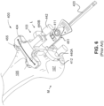
- the kinematic alignment philosophy recognizes that every patient's physiology is slightly different and seeks to restore the patient's natural pre-diseased joint line by taking actual measurements of the operative physiology to ascertain the position of the native joint line. Once these measurements are known, tooling, such as pivoting femoral resection guide locator 400 ( FIGS 2 , 4 and 6 ) or resection guides 424 ( FIG. 6 ) are then placed onto the exposed bones. Resection guides 424 may be custom made to complement the exposed bone or the resection guides 424 can selectively lock into a femoral resection guide locator 400.
- These femoral resection guide locators 400 can have adjustable positioning mechanisms (see 440 ) with which the surgeon can adjust the orientation of the resection guide 424 relative to the exposed bone based on the patient's specific measurements. Once the resection guide 424 is set at the desired orientation, the resection guide 424 is then temporarily affixed to the bone. The surgeon then inserts a surgical saw through a resection slot 455 of the oriented resection guide 424 to resect the undying bone in the desired resection plane.
- the position and orientation of the resection guide 424 largely determines position and orientation of the reconstructed joint axes of rotation.
- the methods and systems described herein may be especially useful for kinematic alignment, nothing in this disclosure limits the use of the systems and methods described herein to kinematic alignment.
- the systems and methods described herein may be used with anatomic alignment, mechanical alignment, or any other alignment method provided that a present bone aberration would affect the positioning of the alignment instruments (see the resection guide locator 400 and the alignment guide 600).
- nothing in this disclosure limits the exemplary systems and methods described herein to use on the knee joint.
- Any orthopedic procedure in which would be desirable for the surgeon to have pre- or intraoperative knowledge of a bone or soft tissue aberration are considered to be within the scope of this disclosure. Examples of such orthopedic procedures include but are not limited to hip arthroplasties, and procedures that seek to alleviate the causes of femoroacetabular impingements.
- FIG. 1 is an anterior view of a simplified left knee joint ( i.e. , an example collection of subject orthopedic elements 100 in an example operative area 170 ) .
- the examples described with reference to FIGS. 1 - 5 relate to an exemplary knee joint for illustration purposes.
- the "orthopedic element" 100 referenced throughout this disclosure is not limited to the anatomy of a knee joint, but can include any skeletal structure and associated soft tissue, such as tendons, ligaments, cartilage, and muscle.
- example orthopedic elements 100 includes any partial or complete bone from a body, including but not limited to a femur, a tibia, a pelvis, a vertebra, a humerus, an ulna, a radius, a scapula, a skull, a fibula, a clavicle, a mandible, a rib, a carpal, a metacarpal, a metatarsal, a phalange, or any associated tendon, ligament, skin, cartilage, or muscle. It will be appreciated that an example operative area 170 can comprise several subject orthopedic elements 100.
- the example orthopedic elements 100 depicted in FIG. 1 are the distal aspect of the femur 105, the proximal aspect of the tibia 110, the proximal aspect of the fibula 11, the medial collateral ligament ("MCL”) 113, the lateral collateral ligament (“LCL”) 122, and articular cartilage 123 disposed over the femoral distal condyles 107, 103.
- Areas of bone aberration are shown on the femoral distal condyles 107, 103.
- a medial area of bone aberration 115a is shown in the medial condyle 107 and a lateral area of bone aberration 115b is shown in the lateral condyle 103 of the femur 105 (collectively, “distal femoral condyles”).
- the areas of bone aberration 115a, 115b are "negative bone aberrations," i.e. , areas of bone loss.
- FIG. 1 depicts the medial condyle 107 and the lateral condyle 103 of the distal aspect of the femur 105 disposed over the tibial plateau 112 of the proximal aspect of the tibia 110.
- the MCL 113 engages the distal femur 105 to the proximal tibia 110 on the medial side M.
- the LCL 122 engages the distal femur 105 to the fibula 111 on the lateral side L.
- a femorotibial gap 120 separates the distal femur 105 from the tibial plateau 112.
- Hyaline articular cartilage 123 is shown around the areas of bone aberration 115a, 115b on the distal femur 105.
- the position of the native pre-diseased joint line is largely set by the interaction between the soft tissue (e.g. , articular cartilage 123) on femoral condyles 107, 103 and the meniscus as supported by the underlying bone ( e.g., the tibia 110).
- the soft tissue e.g. , articular cartilage 123
- the meniscus as supported by the underlying bone (e.g., the tibia 110).
- knowing the thickness of the pre-diseased cartilage 123 can be used to closely approximate the location of the pre-diseased joint line.
- FIG. 7 depicts an example cartilage thickness gauge 40.
- the depicted thickness gauge 40 comprises an elongated handle portion 52, which a surgeon can use to hold and manipulate the instrument.
- a shoulder 62 engages a shaft portion 60 to the handle portion 52.
- the shaft portion 60 comprises a proximal solid portion 63 and a distal hollow portion 64.
- the hollow portion 64 extends to the measurement end 41.
- the hollow portion 64 receives a piston 80.
- the piston 80 is disposed within the hollow portion 64 and biased against a spring 79 disposed between the piston 80 and the solid portion 63 of the shaft portion 60.
- Markers (not depicted) on the piston 80 may be visible through a viewing portal in the shaft portion 60. These markers are desirably disposed at regular increments, such as 1 millimeter (“mm”) increments.
- a reference line may be disposed adjacent to the viewing portal. Likewise, the markers that are visible through the viewing portal move relative to the reference line.
- the measurement end 41 of the cartilage thickness gauge 40 is inserted into the thickest area of cartilage 123 adjacent the lesser worn condyle until the tips 86 of the measurement end 41 reaches the underlying bone 106 ( FIG. 1 ). In this manner, pressing the tips 86 of the measurement end 41 into the thickest area of remaining proximal cartilage 123 causes the piston 80 to compress the spring 79. At the same time, the markers on the piston 80 move relative to the reference line and are visible through the viewing portal to thereby indicate the thickness of the cartilage 123 disposed under the measurement end 41. The surgeon then records the amount of remaining cartilage (i.e., the cartilage thickness T) and uses this measurement as an approximation of the amount of cartilage wear on the worn condyle. This process is desirably repeated for each distal femoral condyle 103, 107 and each posterior femoral condyle (107a, 103a, FIG. 5 ).
- a surgeon or technician may use an intra-operative probe to map the location and physical properties of the soft tissue, such as the soft tissue's elasticity and density.
- a system can use this data to calculate an amount of cartilage wear over the condyles.
- the surgeon may drill an intramedullary canal down roughly the center of the distal femur 105, and then place an intramedullary rod 420 (see also FIG. 6 ) into the evacuated intramedullary canal to provide a foundation for selectively disposing referencing instrumentation relative to the distal femur 105.
- a stable portion 451 of the pivoting femoral resection guide locator 400 can be slid onto the intramedullary rod 420 such that adjustment pads 440A, 440B are disposed adjacent to the medial distal femoral condyle 107 and lateral distal femoral condyle 103 respectively.
- the stable portion 451 can be an intramedullary rod holder member, or other device configured to be secured to a fixed position relative to a pivoting body portion 412.
- the body portion 412 is configured to pivot relative to the stable portion 451.
- a pin 411 FIG. 6
- a pin 411 may be closely fitted to and disposed in aligned annular holes in the stable portion 451 and the body portion 412 respectively and in this manner, the body portion 412 of the pivoting femoral resection guide locator 400 can be said to "configured to pivot" relative to the stable portion 451, or be said to be in a "pivoting relationship" with the stable portion 451.
- each adjustment pad 440A, 440B ( FIG. 6 ) are then extended from the distal reference surface 485 of the resection guide locator 400 to touch the femoral condyles 103, 107.
- the length l of each adjustment pad 440 relative to the reference surface 485 is desirably the same length l as the measurement of the thickness T of the associated adjacent hyaline articular cartilage 123 for each condyle.
- the surgeon will extend the medial adjustment pad 440A 2 mm.
- the surgeon places each adjustment pad 440 on the appropriate condyle.
- the lateral adjustment pad 440B would remain nearly flush with the distal reference surface 485.
- the position of the distal reference surface 485 relative to the intramedullary rod 420 thereby sets the resection angle.
- the resection guide 424 ( FIG.
- the femoral resection guide locator 400 is removed, and the surgeon resects the distal femoral condyles 103, 107 through the resection slot 455 at the desired resection angle.
- the adjustment pads 440A, 440B are typically set based on the measurement of the cartilage thickness gauge 40. If a patient suffers from significant bone loss, of if significant osteophytes (commonly referred to as "bone spurs") are present, the position of distal reference surface 485 of the femoral resection guide locator 400 will not be disposed at the precise location of the pre-diseased articular surface.
- any adjustment of the adjustment pad 440 to touch a condyle having areas of significant bone loss is at best an approximation of the pre-diseased articular surface. Lacking precision in this area risks miscalculating the orientation of the natural pre-diseased rotational axis of the joint. As such, any estimation error can negatively affect patient comfort and the useful life of the implant.
- FIG. 2 shows a side view of a femoral resection guide locator 400 having an adjustment pad 440B extending through a negative area of bone aberration 115b to be disposed on an exposed surface of worn bone 116 on the lateral condyle 103.
- the extended length l of the pad adjuster 440 relative to the distal reference surface 485 is initially set by the measurement of the cartilage thickness (see 123), which may be obtained using the cartilage thickness gauge 40 as described above, or by other cartilage thickness measurement methods.
- the cartilage thickness see 123
- the precise depth of the negative bone aberration (i.e. , bone loss) on the lateral condyle 103 is not easily ascertainable using conventional methods. Improperly accounting for the depth of the negative bone aberration risks misalignment of the pivoting femoral resection guide locator 400 because extending the pad adjuster 440B to the value of the measured cartilage thickness and placing the end of the pad adjuster 440B on the exposed surface of the worn bone 116 is now no longer indicative of the pre-diseased articular surface.
- the pad adjuster 440B As the surgeon initially sets the extended length l of the depicted pad adjuster 440B to 2 mm from the distal reference surface 485 (per the cartilage gauge measurement), and then disposes the pad adjuster 440 such that the pad adjuster 440 contacts the exposed surface of the worn bone 116, the pad adjuster would extend into the area of bone loss 115b by the unknown depth of the negative bone aberration 115b, thereby changing the angle of the distal reference surface 485 (and by extension, the cutting surface) relative to the intramedullary rod 420. This new cutting angle is not reflective of the pre-diseased articular surface and therefore would not be useful to align the knee kinematically.
- the surgeon may attempt to compensate by adding length (see l ) to the pad adjuster 440 to try to estimate the depth of bone loss, but the precise amount of loss is unknown to the surgeon. Therefore, the surgeon may over or under-estimate the amount of loss, thereby also risking misalignment of the femoral resection guide locator 400 relative to the actual articular surface of the pre-diseased joint.
- Kinematic alignment is a femoral articular surface referencing technique. Therefore, mistakes made when referencing the articular surface will be transferred to the proximal tibia if not corrected, thereby potentially further exacerbating the initial error.
- FIG. 2 illustrates, the area of bone aberration 115b, and the exposed surface of the worn bone 116 may not be uniform in depth. This can undermine the initial stability of the resection guide locator's angled position relative to the intramedullary rod 420.
- the object through which the X-ray passes can deflects the path of the X-ray as it travels from the X-ray source (typically the anode of the X-ray machine) to the X-ray detector (which may include by non-limiting example, X-ray image intensifiers, phosphorus materials, flat panel detectors "FPD" (including indirect conversion FPDs and direct conversion FPDs), or any number of digital or analog X-ray sensors or X-ray film).
- FPD flat panel detectors
- Defects in the X-ray machine itself or in its calibration can also undermine the usefulness of X-ray photogrammetry and 3D model reconstruction. Additionally, emitted X-ray photons have different energies.
- noise and artifacts can be produced in part because of Compton and Rayleigh scattering, the photoelectric effect, extrinsic variables in the environment or intrinsic variables in the X-ray generation unit, X-ray detector, and/or processing units or displays.
- the 3D data of the actual subject is lost.
- CT scans, MRIs, and other imaging technologies that preserve third dimensional data were often preferred inputs for reconstructing models of one or more subject orthopedic elements (i.e. , reconstructing a 3D model from actual 3D data generally resulted in more accurate, higher resolution models).
- the present disclosure overcomes these issues by using deep learning networks to improve the accuracy of reconstructed 3D models generated from X-ray photogrammetry and to identify areas of bone aberration on or in the reconstrued 3D model.
- the areas of bone aberration can be corrected or eliminated using curve fitting algorithms (i.e. , an example surface adjustment algorithm).
- An exemplary method for calculating the extent of a bone aberration can comprise: generating a 3D model of an operative area 170 from at least two 2D images, wherein a first image is captured at a first transverse position, wherein a second image is captured at a second transverse position, and wherein the first transverse position is different than the second transverse position, identifying an area of a bone aberration on the 3D model, and calculating a corrective area, wherein the corrective area removes the area of bone aberration from the 3D model ( i.e. , relative to a surrounding bone area).
- An exemplary system for calculating the extent of a bone aberration can comprise: a radiographic imaging machine 1800 comprising an emitter 21 and a detector 33 ( FIG. 18 ), wherein the detector 33 of the radiographic imaging machine 1800 captures a first image 30 ( FIGS. 9 and 10 ) in a first transversion position 30a ( FIGS. 9 and 10 ) and a second image 50 ( FIGS. 9 and 10 ) in a second transverse position 50a ( FIGS. 9 and 10 ), wherein the first transverse position 30a is offset from the second transverse position 50a by an offset angle ⁇ ( FIG. 10 ), a transmitter 29 ( FIG.
- the transmitter 29 transmits the first image 30 and the second image 50 from the detector 33 to the computational machine 1600, and wherein the computational machine 1600 is configured to identify an area of a bone aberration 115 on the 3D model of the subject orthopedic element 1100, and calculate a corrective area, wherein the corrective area removes the area of bone aberration from the 3D model of the subject orthopedic element 1100 ( i.e. , relative to a surrounding bone area).
- an exemplary system may further comprise a display 19.
- An exemplary system may further comprise a manufacturing machine 18.
- the manufacturing machine 18 can be an additive manufacturing machine.
- the additive manufacturing machine may be used to manufacture the 3D model of the subject orthopedic element 1100 or the 3D model of the bone aberration 115m.
- X-ray radiographs from an X-ray imaging system may be desirable because X-ray radiographs are relatively inexpensive compared to CT scans and because the equipment for some X-ray imaging systems, such as a fluoroscopy system, are generally sufficiently compact to be used intraoperatively, nothing in this disclosure limits the use of the 2D images to X-ray radiographs unless otherwise expressly claimed, nor does anything in this disclosure limit the type of imaging system to an X-ray imaging system.
- Other 2D images can include by way of example: CT-images, CT-fluoroscopy images, fluoroscopy images, ultrasound images, positron emission tomography ("PET”) images, and MRI images.
- Other imaging systems can include by way of example: CT, CT-fluoroscopy, fluoroscopy, ultrasound, PET, and MRI systems.
- the exemplary methods can be implemented on a computer platform (e.g. , a computational machine 1600 ) having hardware such as one or more central processing units (CPU), a random access memory (RAM), and input/output (I/O) interface(s).
- a computer platform e.g. , a computational machine 1600
- hardware such as one or more central processing units (CPU), a random access memory (RAM), and input/output (I/O) interface(s).
- CPU central processing units
- RAM random access memory
- I/O input/output
- the 3D model of the subject orthopedic element 1100 and/or the 3D model of the bone aberration 115m can be a computer model. In other examples, the 3D model of the subject orthopedic element 1100 and/or the 3D model of the bone aberration 115m can be a physical model.
- one such method may comprise receiving a set of 2D radiographic images of an operative area 170 of a patient with a radiographic imaging system, computing a first 3D model using epipolar geometry principles with a coordinate system of the radiographic imaging system and projective geometry data from the respective 2D images (see FIGS. 9 and 10 ).
- Such an exemplary method may further comprise projecting the first 3D model on the 2D radiographic images and then adjusting the initial 3D model by registering the first and second radiographic images 30, 50 on the first 3D model with an image-to-image registration technique. Once the image-to-image registration technique has been applied, a revised 3D model may be generated. This process can repeat until the desired clarity in achieved.
- a deep learning network also known as a “deep neural network” (“DNN”), such as a convolutional neural network (“CNN”), recurrent neural network (“RNN”), modular neural network, or sequence to sequence model
- DNN deep neural network
- CNN convolutional neural network
- RNN recurrent neural network
- modular neural network modular neural network, or sequence to sequence model
- the 2D images are desirably tissue penetrating images, such as radiographic images (e.g. , X-ray or fluoroscopy images).
- the deep learning network can generate a model from the projective geometry data (i.e., spatial data 43 or volume data 75) from the respective 2D images.
- the deep learning network can have the advantage of being able to generate a mask of the different subject orthopedic elements 100 (e.g., bones) or bone aberrations 115 in the operative area 170 as well as being able to calculate a volume (see 61, FIG. 11 ) of one or more imaged orthopedic elements 100.
- FIG. 8 is a flow chart that outlines the steps of an exemplary method that uses a deep learning network to identify an area of bone aberration 115 on or in an imaged orthopedic element 100 using two flattened input images (30, 50, FIGs. 9 and 10 ) taken from an offset angle ⁇ .
- the exemplary method comprises: step 1a calibrating an imaging machine 1800 ( FIG. 18 ) to determine a mapping relationship between image points (see X L , e L , X R , e R , FIG. 10 ) and corresponding space coordinates ( e.g., Cartesian coordinates on an x, y plane) to define spatial data 43.
- the imaging machine 1800 is desirably a radiographic imaging machine capable of producing X-ray images ("X-ray images" can be understood to include fluoroscopic images), but all medical imaging machines are considered to be within the scope of this disclosure.
- Step 2a comprises capturing a first image 30 ( FIG. 9 ) of a subject orthopedic element 100 using the imaging technique (e.g. , an X-ray imaging technique, a CT imaging technique, an MRI imaging technique, or an ultrasound imaging technique), wherein the first image 30 defines a first reference frame 30a.
- the imaging technique e.g. , an X-ray imaging technique, a CT imaging technique, an MRI imaging technique, or an ultrasound imaging technique
- the first image 30 defines a first reference frame 30a.
- a second image 50 FIG. 9
- the first image 30 and the second image 50 are input images from which data (including spatial data 43) can be extracted. It will be appreciated that in other examples, more than two images may be used.
- Step 4a comprises projecting spatial data 43 from the first image 30 of the subject orthopedic element 100 and the spatial data 43 from the second image 50 of the subject orthopedic element 100 to define volume data 75 ( FIG. 11 ) using epipolar geometry.
- Step 5a comprises using a deep learning network to detect a bone aberration 115 from the volume data 75 of the orthopedic element 100.
- Step 6a comprises using a deep learning network to detect other features (e.g. , anatomical landmarks) from the volume data 75 of the subject orthopedic element 100 to define a 3D model of the subject orthopedic element 1100.
- Step 7a comprises applying a surface adjustment algorithm to remove the detected bone aberration 115 from the 3D model of the subject orthopedic element 1100.
- the deep learning network that detects the bone aberration 115 from the volume data 75 can be the same deep learning network that detects other features from the volume data 75 of the subject orthopedic element 100. In other examples, the deep learning network that detects the bone aberration 115 from the volume data 75 can be a different from the deep learning network that detects other feature from the volume data 75 of the subject orthopedic element 100.
- the first image 30 can depict the subject orthopedic element 100 in a lateral transverse position (i.e. , the first image 30 is a lateral view of the orthopedic element 100).
- the second image 50 can depict the orthopedic element 100 in an anterior-posterior ("AP") transverse position (i.e. , the second image 50 is an AP view of the orthopedic element 100).
- the first image 30 can depict the orthopedic element 100 in an AP transverse position.
- the second image 50 can depict the orthopedic element 100 in a lateral transverse position.
- neither the first image 30 nor the second image 50 can depict the orthopedic element 100 in an AP transverse position or a lateral transverse position, provided that the first image 30 is offset from the second image 50 by an offset angle ⁇ .
- the computational machine 1600 can calculate the offset angle ⁇ from input images 30, 50 that include the calibration jig (see 973, FIG. 9 ).
- the first image 30 and second image 50 may be referred to collectively as "input images” or individually as an "input image.” These input images 30, 50 desirably depict the same subject orthopedic element 100 from different angles. These input images 30, 50 can be taken along a transverse plane of the subject orthopedic element 100.
- Certain exemplary methods can further comprise using a style transfer deep learning network such as Cycle-GAN.
- Methods that use a style transfer deep learning network may start with a radiographic input image (e.g. , 30) and use the style transfer neural network to transfer the style of the input image to a DRR type image.
- Yet further exemplary methods may comprise using a deep learning network to identify features (e.g. , anatomical landmarks) of the subject orthopedic element 100 or bone aberration 115 to provide a segmentation mask for each subject orthopedic element 100 or bone aberration 115.
- FIGs. 10 and 11 illustrate how the first input image 30 and the second input image 50 can be combined to create a volume 61 comprising volume data 75.
- FIG. 10 illustrates basic principles of epipolar geometry than can be used to convert spatial data 43 from the respective input images 30, 50 into volume data 75 ( FIG. 11 ).
- the spatial data 43 is defined by a collection of image points (e.g., X L , X R ) mapped to corresponding space coordinates ( e.g., x and y coordinates) for a given input image 30, 50.
- FIG. 10 is a simplified schematic representation of a perspective projection described by the pinhole camera model.
- FIG. 10 conveys basic concepts related to computer stereo vison, but it is by no means the only method by which 3D models can be reconstructed from 2D stereo images.
- rays emanate from the optical center (i.e., the point within a lens at which the rays of electromagnetic radiation (e.g., visible light, X-rays, etc.) from the subject object are assumed to cross within the imaging machine's sensor or detector array 33 ( FIG. 18 ).
- the optical centers are represented by points O L , O R in FIG. 10 .
- the image plane (see 30a, 50a) is usually behind the optical center (e.g., O L , O R ) and the actual optical center is projected onto the detector array 33 as a point, but virtual image planes ( see 30a, 50a) are presented here for illustrating the principles more simply.
- the first input image 30 is taken from a first reference frame 30a
- the second input image 50 is taken from a second reference frame 50a that is different from the first reference frame 30a.
- Each image comprise a matrix of pixel values.
- the first and second reference frames 30a, 50a are desirably offset from one another by an offset angle ⁇ .
- the offset angle ⁇ can represent the angle between the x -axis of the first reference frame 30a relative to the x-axis of the second reference frame 50a.
- Point e L is the location of the second input image's optical center O R on the first input image 30.
- Point e R is the location of the first input image's optical center O L on the second input image 50.
- Points e L and e R are known as "epipoles" or epipolar points and lie on line O L - O R .
- the points X, O L , O R define an epipolar plane.
- the actual optical center is the assumed point at which incoming rays of electromagnetic radiation from the subject object cross within the detector lens
- the rays of electromagnetic radiation can actually be imagined to emanate from the optical centers O L , O R for the purpose of visualizing how the position of a 3D point X in 3D space can be ascertained from two or more input images 30, 50 captured from a detector 33 of known relative position.
- each point (e.g., X L ) of the first input image 30 corresponds to a line in 3D space
- a corresponding point e.g., X R
- these corresponding points e.g., X L , X R
- the lines generated by the corresponding image points must intersect at 3D point X.
- a 3D volume 61 comprising volume data 75 can be reproduced from the two or more input images 30, 50.
- the value of any given 3D point X can be triangulated in a variety of ways.
- a non-limiting list of example calculation methods include the mid-point method, the direct linear transformation method, the essential matrix method, the line-line intersection method, and the bundle adjustment method.
- image points may refer to a point in space, a pixel, a portion of a pixel, or a collection of adjacent pixels.
- 3D point X as used herein can represent a point in 3D space. In certain exemplary applications, 3D point X may be expressed as a voxel, a portion of a voxel, or a collection of adjacent voxels.
- each image detector 33 relative to the other image detector(s) 33 must be determined (or the position of a sole image detector 33 must be determined at the point in time in which the first image 30 was taken and the adjusted position of the sole image detector 33 should be known at the point in time in which the second image 50 was taken). It is also desirable to determine the focal length and the optical center of the imaging machine 1800. To ascertain this practically, the image detector 33 (or image detectors) is/are first calibrated.
- FIGS. 9A and 9B depict calibration jigs 973A, 973B relative to subject orthopedic elements 100.
- the example orthopedic elements 100 are the distal aspect of the femur 105 and the proximal aspect of the tibia 110 that comprise a knee joint.
- the proximal fibula 111 is another orthopedic element 100 imaged in FIGS. 9A and 9B .
- the patella 901 is another orthopedic element 100 shown in FIG. 9B .
- FIG. 9A is an anterior-posterior view of the example orthopedic elements 100 ( i.e., FIG. 9A represents a first image 30 taken from a first reference frame 30a).
- a first calibration jig 973A is attached to a first holding assembly 974A.
- the first holding assembly 974A may comprise a first padded support 971A engaged to a first strap 977A.
- the first padded support 971A is attached externally to the patient's thigh via the first strap 977A.
- the first holding assembly 974A supports the first calibration jig 973A oriented desirably parallel to the first reference frame 30a ( i.e. , orthogonal to the detector 33).
- a second calibration jig 973B that is attached to a second holding assembly 974B may be provided.
- the second holding assembly 974B may comprise a second padded support 971B engaged to a second strap 977B.
- the second padded support 971B is attached externally to the patient's calf via the second strap 977B.
- the second holding assembly 974B supports the second calibration jig 973B desirably parallel to the first reference frame 30a ( i.e. , orthogonal to the detector 33).
- the calibration jigs 973A, 973B are desirably positioned sufficiently far away from the subject orthopedic elements 100 such that the calibration jigs 973A, 973B do not overlap any subject orthopedic element 100.
- FIG. 9B is a medial-lateral view of the example orthopedic elements 100 ( i.e., FIG. 9B represents a second image 50 taken from a second reference frame 50a).
- the medial-lateral reference frame 50a is rotated or "offset" 90° from the anterior-posterior first reference frame 30a.
- the first calibration jig 973A is attached to the first holding assembly 974A.
- the first holding assembly 974A may comprise a first padded support 971A engaged to a first strap 977A.
- the first padded support 971A is attached externally to the patient's thigh via the first strap 977A.
- the first holding assembly 974A supports the first calibration jig 973A desirably parallel to the second reference frame 50a (i.e., orthogonal to the detector 33).
- a second calibration jig 973B that is attached to a second holding assembly 974B may be provided.
- the second holding assembly 974B may comprise a second padded support 971B engaged to a second strap 977B.
- the second padded support 971B is attached externally to the patient's calf via the second strap 977B.
- the second holding assembly 974B supports the second calibration jig 973B desirably parallel to the second reference frame 50a (i.e., orthogonal to the detector 33).
- the calibration jigs 973A, 973B are desirably positioned sufficiently far away from the subject orthopedic elements 100 such that the calibration jigs 973A, 973B do not overlap any subject orthopedic element 100.
- the patient can desirably be posited in the standing position (i.e. , the leg is in extension) because the knee joint is stable in this orientation (see FIG. 18 ).
- the patient's distance relative to the imaging machine should not be altered during the acquisition of the input images 30, 50.
- the first and second images 30, 50 need not capture the entire leg, rather the image can focus on the joint that will be the subject of the operative area 170.
- Each calibration jig 973A, 973B is desirably of a known size.
- Each calibration jig 973A, 973B desirably has at least four or more calibration points 978 distributed throughout.
- the calibration points 978 are distributed in a known pattern in which the distance from one point 978 relative to the others is known.
- the distance from the calibration jig 973 from an orthopedic element 100 can also be desirably known.
- the calibration points 978 may desirably be defined by metal structures on the calibration jig 973. Metal typically absorbs most X-ray beams that contact the metal.
- metal typically appears very brightly relative to material that absorbs less of the X-rays (such as air cavities or adipose tissue).
- X-rays such as air cavities or adipose tissue.
- calibration points include reseau crosses, circles, triangles, pyramids, and spheres.
- These calibration points 978 can exist on a 2D surface of the calibration jig 973, or 3D calibration points 978 can be captured as 2D projections from a given image reference frame. In either situation, the 3D coordinate (commonly designated the z coordinate) can be set to equal zero for all calibration points 978 captured in the image. The distance between each calibration point 978 is known. These known distances can be expressed as x, y coordinates on the image sensor/detector 33. To map a point in 3D space to a 2D coordinate pixel on a sensor 33, the dot product of the detector's calibration matrix, the extrinsic matrix and the homologous coordinate vector of the real 3D point can be used.
- the above calibration method is provided as an example. It will be appreciated that all methods suitable for calibrating an X-ray photogrammetry system are considered to be within the scope of this disclosure.
- a non-limiting list of other X-ray photogrammetry system calibration methods include the use of a reseau plate, the Zhang method, the bundle adjustment method, direct linear transformation methods, maximum likelihood estimation, a k-nearest neighbor regression approach ("kNN”), other deep learning methods, or combinations thereof.
- FIG. 11 illustrates how the calibrated input images 30, 50, when oriented along the known offset angle ⁇ , can be back projected into a 3D volume 61 comprising two channels 65, 66.
- the first channel 65 contains all the image points (e.g., X L etc .) of the first input image 30 and the second channel 66 contains all the image points ( e.g., X R etc .) of the second input image 50. That is, each image point ( e.g. , pixel) is replicated over its associated back-projected 3D ray.
- epipolar geometry can be used to generate a volume 61 of the imaged operative area 170 comprising volume data 75 from these back projected 2D input images 30, 50.
- the first image 30 and the second image 50 desirably have known image dimensions.
- the dimensions may be pixels.
- the first image 30 may have dimensions of 128 x 128 pixels.
- the second image 50 may have dimensions of 128 x 128 pixels.
- the dimensions of the input images 30, 50 used in a particular computation desirably have consistent dimensions. Consistent dimensions may be desirable for later defining a cubic working area of regular volume 61 ( e.g. , a 128 x 128 x 128 cube).
- the offset angle ⁇ is desirably 90°. However, other offset angles ⁇ may be used in other examples.
- each of the 128 x 128 pixel input images 30, 50 are replicated 128 times over the length of the adjacent input image to create a volume 61 having dimensions of 128 x 128 x 128 pixels. That is, the first image 30 is copied and stacked behind itself at one copy per pixel for 128 pixels while the second image 50 is copied and stacked behind itself for 128 pixels such that stacked images overlap to thereby create the volume 61.
- the volume 61 can be said to comprise two channels 65, 66, wherein the first channel 65 comprises the first image 30 replicated n times over the length of the second image 50 (i.e., the x-axis of the second image 50) and the second channel 66 comprises the second image 50 replicated m times over the length of the first image 30 (i.e., the x-axis of the first image 30), wherein " n " and "m” are the length of the indicated image as expressed as the number of pixels (or other dimensions in other examples) that comprise the length of the indicated image.
- each transverse slice (also known as an "axial slice” by some radiologists) of the volume 61 creates an epipolar plane comprising voxels that are back-projected from the pixels that comprise the two epipolar lines.
- projecting spatial data 43 from the first image 30 of the subject orthopedic element 100 and the spatial data 43 from the second image 50 of the subject orthopedic element 100 defines volume data 75.
- the 3D representation can be reconstructed using epipolar geometric principles as discussed above; the 3D representation is consistent geometrically with the information in the input images 30, 50.
- the deep learning network is a CNN
- the CNN can be structured and trained. All architecture of CNNs are considered to be within the scope of this disclosure. Common CNN architectures include by way of example, LeNet, GoogLeNet, AlexNet, ZFNet, ResNet, and VGGNet.
- FIG. 17 is a schematic representation of a CNN that illustrates how the CNN can be used to identify areas of bone aberrations 115. Without being bound by theory, it is contemplated that a CNN may be desirable for reducing the size of the volume data 75 without losing features that are necessary to identify the desired orthopedic element or the desired areas of bone aberration 115.
- the volume data 75 of the multiple back projected input images 30, 50 is a multidimensional array that can be known as an "input tensor.” This input tensor comprises the input data (which is the volume data 75 in this example) for the first convolution.
- a filter also known as a kernel 69 is shown disposed in the volume data 75.
- the kernel 69 is a tensor (i.e., a multi-dimensional array) that defines a filter or function (this filter or function is sometimes known as the "weight" given to the kernel).
- the kernel tensor 69 is three dimensional.
- the filter or function that comprises the kernel 69 can be programed manually or learned through the CNN, RNN, or other deep learning network.
- the kernel 69 is a 3x3x3 tensor although all tensor sizes and dimensions are considered to be within the scope of this disclosure, provided that the kernel tensor size is less than the size of the input tensor.
- Each cell or voxel of the kernel 69 has a numerical value. These values define the filter or function of the kernel 69.
- a convolution or cross-correlation operation is performed between the two tensors. In FIG. 17 , the convolution is represented by the path 76.
- the path 76 that the kernel 69 follows is a visualization of a mathematical operation. Following this path 76, the kernel 69 eventually and sequentially traverses the entire volume 61 of the input tensor ( e.g. , the volume data 75). The goal of this operation is to extract features from the input tensor.
- Convolution layers 72 typically comprise one or more of the following operations: a convolution stage 67, a detector stage 68, and a pooling stage 58. Although these respective operations are represented visually in the first convolution layer 72a in FIG. 17 , it will be appreciated that the subsequent convolution layers 72b, 72c, etc. may also comprise one or more or all of the convolution stage 67, detector stage 68, and pooling layer 58 operations or combinations or permutations thereof. Furthermore, although FIG. 17 , depicts five convolution layers 72a, 72b, 72c, 72d, 72e of various resolutions, it will be appreciated that more or less convolution layers may be used.
- the kernel 69 is sequentially multiplied by multiple patches of pixels in the input data (i.e., the volume data 75 in the depicted example).
- the patch of pixels extracted from the data is known as the receptive field.
- the multiplication of the kernel 69 and the receptive field comprises an element-wise multiplication between each pixel of the receptive field and the kernel 69. After multiplication, the results are summed to form one element of a convolution output.
- This kernel 69 then shifts to the adjacent receptive field and the element-wise multiplication operation and summation continue until all the pixels of the input tensor have been subjected to the operation.
- the input data e.g ., the volume data 75
- a nonlinear activation function is then employed. Use of such a non-linear function marks the beginning of the detector stage 68.
- the non-linear activation function serves as a threshold for detecting the presence of the feature extracted by the kernel 69. For example, applying a convolution or a cross-correlation operation between the input tensor and the kernel 69, wherein the kernel 69 comprises a low level edge filter in the convolution stage 67 produces a convolution output tensor. Then, applying a non-linear activation function with a bias to the convolution output tensor will return a feature map output tensor. The bias is sequentially added to each cell of the convolution output tensor.
- the non-linear activation function detects the presence of the desired features from the input data (e.g. , the volume data 75 in this example).
- Non-linear activation functions are considered to be within the scope of this disclosure.
- Other examples include the Sigmoid, TanH, Leaky ReLU, parametric ReLU, Softmax, and Switch activation functions.
- Valid padding may be applied to reduce the dimensions of the convolved tensor (see 72b) compared to the input tensor (see 72a).
- a pooling layer 58 is desirably applied to reduce the spatial size of the convolved data, which decreases the computational power required to process the data.
- Common pooling techniques including max pooling and average pooling may be used. Max pooling returns the maximum value of the portion of the input tensor covered by the kernel 69, whereas average pooling returns the average of all the values of the portion of the input tensor covered by the kernel 69. Max pooling can be used to reduce image noise.
- a fully connected layer can be added after the final convolution layer 72e to learn the non-linear combinations of the high level features (such as the profile of an imaged proximal tibia 110 or a bone aberration 115) represented by the output of the convolutional layers.
- the top half of FIG. 17 represents compression of the input volume data 75, whereas the bottom half represents decompression until the original size of the input volume data 75 is reached.
- the output feature map of each convolution layer 72a , 72b, 72c, etc. is used as the input for the following convolution layer 72b, 72c, etc. to enable progressively more complex feature extraction.
- the first kernel 69 may detect edges
- a kernel in the first convolution layer 72b may detect a collection of edges in a desired orientation
- a kernel in a third convolution layer 72c may detect a longer collection of edges in a desired orientation, etc. This process may continue until the entire profile of the medial distal femoral condyle is detected by a downstream convolution layer 72.
- FIG. 17 up-samples (i.e. , expands the spatial support of the lower resolution feature maps.
- a de-convolution operation is performed in order to increase the size of the input for the next downstream convolutional layer (see 72c, 72d, 72e).
- a convolution can be employed with a 1 x 1 x 1 kernel 69 to produce a multichannel output volume 59 that is the same size as the input volume 61.
- Each channel of the multichannel output volume 59 can represent a desired extracted high level feature. This can be followed by a Softmax activation function to detect the desired orthopedic elements 100.
- the depicted example may comprise six output channels numbered 0, 1, 2, 3, 4, 5 wherein channel 0 represents identified background volume, channel 1 represents the identified distal femur 105, channel 2 represents the identified proximal tibia 110, channel 3 represents the identified proximal fibula 111, channel 4 represents the identified patella 901, and channel 5 represents the identified bone aberration 115.
- channel 0 represents identified background volume
- channel 1 represents the identified distal femur 105
- channel 2 represents the identified proximal tibia 110
- channel 3 represents the identified proximal fibula 111
- channel 4 represents the identified patella 901
- channel 5 represents the identified bone aberration 115.
- Select output channels comprising output volume data 59 of the desired orthopedic element 100 or bone aberration 115b can be used to create a 3D model of the subject orthopedic element 1100 or a 3D model of the bone aberration 115m.
- a machine learning algorithm i.e., a deep learning network (such as for example, a CNN)
- the CNN can be used after calibration of the imaging machine but before 2D to 3D reconstruction. That is, the CNN can be used to detect features (e.g., anatomical landmarks) of a subject orthopedic element 100 from the first reference frame 30a and the second reference frame 50a of the respective 2D input images 30, 50.
- a CNN may be used to identify high level orthopedic elements (e.g., the distal femur 105 and any bone aberrations 115) from the 2D input images 30, 50.
- the CNN may then optionally apply a mask or an outline to the detected orthopedic element 100 or bone aberration 115. It is contemplated that is the imaging machine 1800 is calibrated and if the CNN identified multiple corresponding image points ( e.g., X L , X R ) of features between the two input images 30, 50, then the transformation matrices between the reference frames 30a, 50a of a subject orthopedic element 100 can be used to align the multiple corresponding image points in 3D space.
- only the 2D masks or outlines of the identified orthopedic element 100 or bone aberration 115 can be sequentially back-projected in the manner described with reference to FIGs. 10 and 11 supra to define a volume 61 of the identified orthopedic element 100 or bone aberration 115.
- a 3D model of the subject orthopedic element 1100 or a 3D model of the bone aberration 115m may be created.
- first image 30 and the second image 50 are radiographic X-ray images
- training a CNN can present several challenges.
- CT scans typically produce a series of images of the desired volume.
- Each CT image that comprises a typical CT scan can be imagined as a segment of the imaged volume. From these segments, a 3D model can be created relatively easily by adding the area of the desired element as the element is depicted in each successive CT image. The modeled element can then be compared with the data in the CT scan to ensure accuracy.
- radiographic imaging systems typically do not generate sequential images that capture different segments of the imaged volume; rather, all of the information of the image is flattened on the 2D plane.
- the CNN can be trained with CT images, such as digitally reconstructed radiograph ("DRRs") images.
- DRRs digitally reconstructed radiograph
- the neural network can develop its own weights (e.g. , filters) for the kernels 69 to identify a desired orthopedic element 100 or a bone aberration 115b.
- image-to-image translation can be performed to render the input X-ray images to have a DRR-style appearance.
- An example image-to-image translation method is the Cycle-GAN image translation technique.
- the style transfer method is desirably used prior to imputing the data into a deep learning network for feature detection.
- FIG. 12 is a perspective view that depicts a distal femur 105 and 3D models of bone aberrations 115m1, 115m2. It will be appreciated that the 3D models of the bone aberrations 115m1, 115m2 can be produced in accordance with any method or system of this disclosure.
- the distal femur 105 had two negative bone aberrations 115a, 115c ( i.e., areas of bone loss) on the medial condyle 107.
- a method in accordance with this disclosure can be used to identify the bone aberrations 115a, 115c, as described herein.
- the output channel comprising the bone aberration volume data 59 can be used to produce a 3D model of the bone aberration 115m1 .
- the respective 3D models of the bone aberrations 115m1, 115m2 comprise the inverse volume of actual bone aberrations 115a, 115c.
- the deep learning network can be trained to detect the edges of the actual negative bone aberrations 115a, 115c and the curvature of the surface of the adjacent orthopedic element 100 in which the negative bone aberration 115a, 115c resides.
- the surface of the adjacent orthopedic element is the medial condylar surface.
- a surface adjustment algorithm such as for example, a curve-fitting algorithm, can then be applied to estimate the curvature of the missing surface to thereby correct the negative bone aberration 115.
- the estimated curvature can then be added to the identified surface area of the negative bone aberration ( e.g. , 115a).
- the space between the identified surface area of the negative bone aberration and the estimated curvature defines the modeled volume of the negative bone aberration 115a.
- the data comprising this modeled volume can be used to produce a 3D model of the aberration 115m1 that has an inverse modeled volume to the actual volume of the negative bone aberration 115a.
- a deep learning network can be trained to detect the edges of the actual positive bone aberration 115 and the curvature of the surface of the adjacent orthopedic element 100 on which the positive bone aberration 115 resides. If the surface of the adjacent orthopedic element 100 is curved, a curve-fitting algorithm can be used to estimate the curvature of the surface without the positive bone aberration 115 to thereby correct the positive bone aberration 115.
- a 3D model of the bone aberration 115m1 can be produced as a physical 3D bone aberration model. If used intraoperatively, the physical 3D model of the bone aberration 115m1 may be created at 1: 1 scale. In such examples, the physical 3D model of the bone aberration 115m1 may be made from a medical-grade polyamide (informally known as nylon).
- the material of the physical 3D model of the bone aberration 115m1 should be sterilizable and can desirably have properties suitable for an autoclave. Autoclaves are generally small and compact, which makes them especially useful for sterilizing the physical 3D model of the bone aberration 115m1 at or near the surgical center.
- suitable materials for the 3D model of the bone aberration 115m1 include a medical grade polyethylene (e.g. , ultra-high molecular weight polyethylene (“UHMWPE”), a polyether ether ketone (“PEEK”), or other biocompatible, clinically proven materials, including but not limited to, cobalt chrome molybdenum alloys, titanium alloys, and ceramic materials, including but not limited to zirconia toughened alumina (“ZTA”) ceramics.
- UHMWPE ultra-high molecular weight polyethylene
- PEEK polyether ether ketone
- ZTA zirconia toughened alumina
- an advantage of a 1:1 physical 3D model of the bone aberration 115m1 is that the physical 3D model of the bone aberration 115m1 has a complementary surface of the exposed surface 116 of the actual bone aberration (see 115b, FIG. 2 , 4 ).
- the physical 3D bone aberration model 115m1 can be placed adjacent to the complementary surface 116 of the actual bone aberration 115b intraoperatively. In this manner, the uncertainty described above with reference to FIG. 2 supra is obviated.
- the physical 3D model of the bone aberration 115m2 can be selectively attached to one or both posterior pads 693a, 693b of the alignment guide 600. It is contemplated that by providing a physical sterilized model of the missing bone, the uncertainty described with reference to FIG. 5 infra is eliminated.
- FIG. 3 is an anterior view of a simplified left knee joint visually representing the step of using a deep learning network to detect a bone aberration 115a, 115b on or in the volume data 75 of the orthopedic element 100.
- the deep learning network can detect other landmarks from the volume data 75 of the subject orthopedic element 100 to define a 3D model of the subject orthopedic element 1100.
- a surface adjustment algorithm is then applied to remove the bone aberration 115a, 115b from the 3D model of the subject orthopedic element 1100.
- the bone aberration 115a, 115b is removed by calculating an external missing bone surface 117a, 117b that matches the outer surface of the bone aberration 115a, 115b (in this case, the outer surface area of bone loss).
- a computer platform executing the exemplary method can run software that is trained via artificial intelligence to identify features (i.e., landmarks) on the worn condyles that would be indicative of bone loss on the 3D model.
- features i.e., landmarks
- a person can manually identify the borders of bone loss via a computer interface to identify the area of the bone aberration 115a, 115b.
- a surface adjustment algorithm may be applied to calculate an external missing bone surface 117a, 117b that fits the outer surface area of the bone aberration 115a, 115b in situations in which the bone aberration constitutes bone loss.
- the step of using the deep learning network to detect a bone aberration 115a, 115b on or in the volume data 75 of the orthopedic element 100 further comprises generating a 3D model of the bone aberration 115m.
- the 3D bone aberration model 115m is a computer model
- the 3D bone aberration model 115m may optionally be projected on a display 19, such as a screen.
- the 3D bone aberration computer model 115m may be projected within the surgeon's field of view to overlay the actual bone aberration 115 in an image of the operative area 170.
- the 3D bone aberration computer model 115m may be projected within the surgeon's field of view to overlay the actual bone aberration 115 in the patient, such as in the exposed operative area 170.
- a display 19 may be accomplished through an augmented reality device, preferably a head-mounted augmented reality device.
- a physical 3D bone aberration model 115m may be created through a manufacturing technique (see FIG. 18 ).
- Said manufacturing technique may comprise a reductive manufacturing method such as through use of a computer numerical control ("CNC") machine or a milling machine.
- the manufacturing technique may comprise an additive manufacturing technique such as a 3D printing technique. If the manufacturing technique is an additive manufacturing technique, the physical 3D bone aberration model 115m may be manufactured at the preoperative center, offsite, or on or proximal to the operative premise.
- FIG. 4 is a side view of a pivoting femoral resection guide locator 400 having an adjustment pad 440 with an adjustment knob 442 extending to a calculated external missing bone surface 117b a lateral condyle 103.
- the adjustment pad 440 can be thought of as extending to the pre-diseased surface of the bone.
- the surgeon may instead choose to add the depth of bone loss to the ascertained depth of cartilage loss, set the length l of the adjustment pad 440 to reflect the combined sum of the maximum bone depth loss and the depth of cartilage loss, and then place the adjustment pad 440 on the remaining exposed bone 116 of the lateral condyle. In this manner, the distal reference surface 485 is now disposed at the articular surface of the pre-diseased joint with precision.
- a 1:1 physical 3D bone aberration model 115m can be affixed to the distal end of the adjustment knob 440 such that a complementary surface of the 1:1 physical 3D bone aberration model 115m mates with the surface 116 of the bone aberration 115b when the adjustment knob 440 is disposed adjacent to the exposed bone aberration 115b (see FIG. 17 ).
- the physical 3D bone aberration model 115m1 can comprise the volume of the bone loss as described above plus the modeled surface of the missing cartilage.
- a surface adjustment algorithm can be used to define the surface of the missing cartilage relative to the surface of the surrounding cartilage.
- FIG. 5 is a perspective view of a simplified distal end of the femur 105 depicted after the distal resection has been made with the resection guide 424.
- An alignment guide 600 comprising posterior pads 693a, 693b is disposed under the posterior portion 103a, 107a of the femoral condyles 103, 107.
- the posterior portion of the femoral condyles will be referred to as "posterior condyles" 103a, 107a.
- the alignment guide 600 can be a combined sizing and alignment guide as depicted herein, or just an alignment guide 600.
- the alignment guide 600 can comprise a body 602.
- the posterior pads 693a, 693b extend from an inferior portion of the body 602 and drill bores 642a, 642b extend through the body 602 above the posterior pads 693a, 693b.
- a pivot drill bore 642a extends through the body 602 of the alignment guide 600 and a radial drill bore 642b is disposed radially distal from the pivot drill bore 642a.
- the radial drill bore 642b also extends through the body 602 of the alignment guide 600.
- the surgeon places the posterior pads 693a, 693b under the respective posterior condyles 103a, 107a such that the body 602 is disposed adjacent to the resected surface 603 of the distal femur 105.
- the surgeon measures the thickness of the remaining articular cartilage on the posterior condyles 103a, 107a and set the length of the posterior pads 693a, 693b to reflect the amount of cartilage wear (similar to the way described supra with reference to FIG. 2 ). Adjustment of the position of the posterior pads 693a, 693b relative to the body 602 causes the radial drill bore 642b to pivot around the pivot drill bore 642a. Once the surgeon is satisfied with the angle, the surgeon can lock the angle of the pivoting section of the alignment guide 600 in place.
- the surgeon can then drill into the resected surface 603 via the drill bores 642a, 642b and then insert pins into the respective drill bores 642a, 642b.
- the surgeon may then remove the alignment guide 600 and leave the pins.
- the angle of these pins defines the angle at which further resection guide (commonly known as a "four-in-one cutting block") can be placed next to the resected surface.
- the four-in-one cutting block has additional resection slots that allow the surgeon to make the anterior, posterior, and chamfer resections using a single "cutting block.” These additional resections create a profile on the distal femur 105 upon which trial implants (and eventually the actual endoprosthetic implant) can be placed.
- a negative bone aberration (e.g. , bone loss) 115c can be less common on the posterior portions 103a, 107a of the femoral condyles 103, 107 but such bone loss is still possible, especially in advanced degenerative diseases.
- Negative bone aberrations 115c of the posterior condyles 103a, 107a presents similar problems in accurately replicating the natural articular surface of the pre-diseased joint, particularly in kinematic alignment.
- the medial posterior condyle 107a has a negative bone aberration 115 as shown in FIG. 5 , it was previously impossible to know with certainty how to adjust the depicted alignment guide to account for the amount of bone wear present.
- Over-adjusting the medial posterior pad 693a would change the position of where the respective drill bores 642a, 642b were located relative to the resected surface 603 and could change the pivot angle of the respective drill bores 642a, 642b.
- the pins could be misplaced.
- the position of the four-in-one cutting block would also be displaced by virtue of sliding over misplaced pins. Misplaced anterior, posterior, and chamfer resections could result in imprecisely seating the femoral component of the endoprosthetic implant.
- a 1:1 physical 3D bone aberration model 115m can be affixed to the end of the posterior pads 693a, 693b such that a complementary surface (also known as a "mating surface") of the 1: 1 physical 3D bone aberration model 115m mates with the surface 116c of the bone aberration 115c when the posterior pad 693a is disposed adjacent to the exposed bone aberration 115c.
- the mating surface of the physical 3D bone aberration model can comprise one or more projections (e.g. , spike, pins, or other protections). These projections can be hammered or otherwise forcibly inserted through the worn surface 116c of the bone aberration 115c, to thereby secure the physical model of the bone aberration 115m into the negative bone aberration 115c to thereby eliminate the negative bone aberration 115c.
- Using an alignment guide 600 with the physical 3D bone aberration model in this manner can ensure more accurate referencing.
- some four-in-one cutting blocks have markings that are designed to reference the surface of the posterior condyles 107a, 103a.
- the physical 3D bone aberration model 115m2 can comprise the volume of the bone loss as described above plus the modeled surface of the missing cartilage.
- a surface adjustment algorithm can be used to define the surface of the missing cartilage relative to the surface of the surrounding cartilage. In this manner, the articular surface of the condyle can be accurately recreated, thereby substantially increasing the precision of the articular surface referencing.
- a shim having a height that equals the maximum depth of the negative bone aberration, the depth of the missing articular cartilage, or the combined maximum depth of the negative bone aberration and the depth of the missing articular cartilage can be added to one or more of the posterior pads 693a, 693b to offset the amount of wear and substantially recreate the position of the pre-diseased articular surface.
- a computer platform having hardware such as one or more central processing units (“CPU”), a random access memory (“RAM”), and input/output (“I/O") interface(s) can receive at least two 2D radiographic images taken at different orientations along a transverse plane. The orientations are preferably orthogonal to each other.
- the computer platform can then run a machine learning software application that identifies an area of bone loss 115a, 115b, 115c and that applies a surface adjustment algorithm to calculate an external missing bone surface 117a, 117b, 117c that fits the area of bone loss 115a, 115b, 115c.
- the computer platform may optionally display the 3D computer model 1100.
- the computer platform may further display the external missing bone surface 117a, 117b, 117c over the area of bone loss 115a, 115b, 115c to allow the viewer to visualize the pre-diseased external missing bone surface 117a, 117b, 117c.
- the surgeon can use this data to set the posterior pads 693a, 693b of alignment guide 600 to reflect the articular surface of the pre-diseased posterior condyles 103a, 107a.
- FIG. 16 generally depicts a block diagram of an exemplary computational machine 1600 upon which one or more of the methods discussed herein may be performed.
- the computational machine 1600 can operate on a single machine.
- the computational machine 1600 can comprise connected ( e.g. , networked) machines.
- networked machines that can comprise the exemplary computational machine 1600 include by way of example, cloud computing configurations, distributed hosting configurations, and other computer cluster configurations.
- one or more machines of the computational machine 1600 can operate in the capacity of a client machine, a server machine, or both a server-client machine.
- the computational machine 1600 can reside on a personal computer ("PC"), a mobile telephone, a tablet PC, a web appliance, a personal digital assistant ("PDA”), a network router, a bridge, a switch, or any machine capable of executing instructions that specify actions to be undertaken by said machine or a second machine controlled by said machine.
- PC personal computer
- PDA personal digital assistant
- Example machines that can comprise the exemplary computational machines 1600 can include by way of example, components, modules, or like mechanisms capable of executing logic functions.
- Such machines may be tangible entities (e.g., hardware) that is capable of carrying out specified operations while operating.
- the hardware may be hardwired ( e.g., specifically configured) to execute a specific operation.
- such hardware may comprise configurable execution media (e.g., circuits, transistors, logic gates, etc.) and a computer-readable medium having instructions, wherein the instructions configure the execution media to carry out a specific operation when operating.
- the configuring can occur via a loading mechanism or under the direction of the execution media.
- the execution media selectively communicate to the computer-readable medium when the machine is operating.
- the execution media may be configured by a first set of instructions to execute a first action or set of actions at a first point in time and then reconfigured at a second point in time by a second set of instructions to execute a second action or set of actions.
- the exemplary computational machine 1600 may include a hardware processor 1697 (e.g. , a CPU, a graphics processing unit (“GPU”), a hardware processor core, or any combination thereof, a main memory 1696 and a static memory 1695, some or all of which may communicate with each other via an interlink (e.g., a bus) 1694.
- the computational machine 1600 may further include a display unit 1698, an input device 1691 (preferably an alphanumeric or character-numeric input device such as a keyboard), and a user interface (“UI”) navigation device 1699 (e.g., a mouse or stylus).
- the input device 1691, display unit 1698, and UI navigation device 1699 may be a touch screen display.
- the display unit 1698 may include holographic lenses, glasses, goggles, other eyewear, or other AR or VR display components.
- the display unit 1698 may be worn on a head of a user and may provide a heads-up-display to the user.
- the input device 1691 may include a virtual keyboard (e.g., a keyboard displayed virtually in a virtual reality ("VR") or an augmented reality (“AR”) setting) or other virtual input interface.
- VR virtual reality
- AR augmented reality
- the computational machine 1600 may further include a storage device (e.g., a drive unit) 1692, a signal generator 1689 (e.g., a speaker) a network interface device 1688, and one or more sensors 1687, such as a global positioning system ("GPS") sensor, accelerometer, compass, or other sensor.
- the computational machine 1600 may include an output controller 1684, such as a serial (e.g. , universal serial bus ("USB”), parallel, or other wired or wireless (e.g., infrared (“IR”) near field communication (“NFC”), radio, etc.) connection to communicate or control one or more ancillary devices.
- a serial e.g. , universal serial bus (“USB)
- USB universal serial bus
- IR infrared
- NFC near field communication
- radio etc.
- the storage device 1692 may include a machine-readable medium 1683 that is non-transitory, on which is stored one or more sets of data structures or instructions 1682 (e.g., software) embodying or utilized by any one or more of the functions or methods described herein.
- the instructions 1682 may reside completely or at least partially, within the main memory 1696, within static memory 1695, or within the hardware processor 1697 during execution thereof by the computational machine 1600.
- one or any combination of the hardware processor 1697, the main memory 1696, the static memory 1695, or the storage device 1692 may constitute machine-readable media.
- machine-readable medium 1683 is illustrated as a single medium, the term, "machine readable medium” may include a single medium or multiple media (e.g. , a distributed or centralized database, or associated caches and servers) configured to store the one or more instructions 1682.
- machine readable medium may include a single medium or multiple media (e.g. , a distributed or centralized database, or associated caches and servers) configured to store the one or more instructions 1682.
- machine-readable medium may include any medium that is capable of storing, encoding, or carrying instructions for execution by the computational machine 1600 and that cause the computational machine 1600 to perform any one or more of the methods of the present disclosure, or that is capable of storing, encoding, or carrying data structures used by or associated with such instructions.
- a non-limited example list of machine-readable media may include magnetic media, optical media, solid state memories, non-volatile memory, such as semiconductor memory devices (e.g. , electronically erasable programable read-only memory (“EEPROM”), electronically programmable read-only memory (“EPROM”), and magnetic discs, such as internal hard discs and removable discs, flash storage devices, magneto-optical discs, and CD-ROM and DVD-ROM discs.
- EEPROM electronically erasable programable read-only memory
- EPROM electronically programmable read-only memory
- magnetic discs such as internal hard discs and removable discs, flash storage devices, magneto-optical discs, and CD-ROM and DVD-ROM discs.
- the instructions 1682 may further be transmitted or received over a communications network 1681 using a transmission medium via the network interface device 1688 utilizing any one of a number of transfer protocols (e.g. , internet protocol (“IP”), user datagram protocol (“UDP”), frame relay, transmission control protocol (“TCP”), hypertext transfer protocol (“HTTP”), etc.)
- Example communication networks may include a wide area network (“WAN”), a plain old telephone (“POTS”) network, a local area network (“LAN”), a packet data network, a mobile telephone network, a wireless data network, and a peer-to-peer (“P2P”) network.
- the network interface device 1688 may include one or more physical jacks (e.g., Ethernet, coaxial, or phone jacks) or one or more antennas to connect to the communications network 1681.
- the network interface device 1688 may include a plurality of antennas to communicate wirelessly using at least one of a single-input multiple-output (“SIMO"), or a multiple-input single output (“MISO”) methods.
- SIMO single-input multiple-output
- MISO multiple-input single output
- transmission medium includes any intangible medium that is capable of storing, encoding, or carrying instructions for execution by the computational machine 1600, and includes analog or digital communications signals or other intangible medium to facilitate communication of such software.
- Exemplary methods in accordance with this disclosure may be machine or computer-implemented at least in part. Some examples may include a computer-readable medium or machine-readable medium encoded with instructions operable to configure an electronic device to perform the exemplary methods described herein.
- An example implementation of such an exemplary method may include code, such as assembly language code, microcode, a higher-level language code, or other code. Such code may include computer readable instructions for performing various methods. The code may form portions of computer program products. Further, in an example, the code may be tangibly stored on or in a volatile, non-transitory, or non-volatile tangible computer-readable media, such as during execution or other times. Examples of these tangible computer-readable media may include, but are not limited to, removable optical discs (e.g. , compact discs and digital video discs), hard drives, removable magnetic discs, memory cards or sticks, include removable flash storage drives, magnetic cassettes, random access memories (RAMs), read only memories (ROMS), and other media.
- removable optical discs e.g.
- the surface adjustment algorithm can be a curve fitting algorithm.
- An exemplary curve fitting algorithm may involve interpolation or smoothing.
- the curve fitting algorithm may be used to extrapolate the position of the pre-diseased articular surface of the bone.
- the surface adjustment algorithm can identify the dimensions of a non-worn contralateral orthopedic element 100, such as a non-worn contralateral condyle.
- the surface adjustment algorithm can add the surface of the non-worn orthopedic element to the corresponding area of bone loss on the worn orthopedic element 100 to calculate the external missing bone surface 117a, 117b.
- an initial missing bone surface calculation based on the measurements of the non-worn orthopedic element 100 can be increased or reduced to fit the curve of the non-worn portions of the worn orthopedic element 100.
- the surface adjustment algorithm can calculate a maximum depth of bone loss. In a such an example, this maximum depth may be added to the depth of articular cartilage loss to calculate the position of the pre-diseased articular surface for each condyle. In still other examples, a volume 61 of the area of bone loss 115a, 115b may be calculated. It will be appreciated that any disclosed calculations or the results of any such calculations may optionally be displayed on a display 19. In other examples, the method may further comprise ascertaining a depth of missing articular cartilage that would have overlaid the external missing bone surface and adding the depth of the missing articular cartilage to the external missing bone surface to define a pre-diseased articular condylar surface.
- FIG. 13 is a flow chart that outlines the steps of an exemplary method that uses a deep learning network to identify an area of bone aberration 115 on or in an imaged orthopedic element 100 using two flattened input images taken from an offset angle ⁇ .
- the exemplary method comprises: Step 1b calibrating an imaging machine to determine a mapping relationship between image points and corresponding space coordinates to define spatial data 43.
- Step 2b comprises using an imaging technique to capture a first image 30 of a subject orthopedic element 100, wherein the first image 30 defines a first reference frame 30a.
- Step 3b comprises using the imaging technique to capture a second image 50 of the subject orthopedic element 100, wherein the second image 50 defines a second reference frame 50a, and wherein the first reference frame 30a is offset from the second reference frame 50a at an offset angle ⁇ .
- Step 4b comprises projecting spatial data 43 from the first image 30 of the subject orthopedic element 100 and spatial data 43 from the second image 50 of the subject orthopedic element 100 to define volume data 75.
- Step 5b comprises using a deep learning network to detect the subject orthopedic element 100 using the volume data 75, the volume data 75 defining an anatomical landmark on or in the subject orthopedic element 100.
- Step 6b comprises using a deep learning network to detect a bone aberration 115 on or in the subject orthopedic element 100 using the volume data 75.
- Step 7b comprises using the deep learning network to apply a mask to the subject orthopedic element 100 defined by the anatomical landmark.
- Step 8b comprises applying the deep learning network to the volume data 75 to generate a 3D model of the subject orthopedic element 100.
- Step 9b comprises applying a surface adjustment algorithm to remove the bone aberration 115 from the 3D model of the subject orthopedic element 1100.
- FIG. 14 is a flow chart that outlines the steps of an exemplary method that uses a deep learning network to identify an area of bone aberration 115 on or in an imaged orthopedic element 100 using two flattened input images taken from an offset angle ⁇ .
- the exemplary method comprises: step 1c calibrating a radiographic imaging machine to determine a mapping relationship between radiographic image points and corresponding space coordinates to define spatial data 43.
- Step 2c comprises using a radiographic imaging technique to capture a first radiographic image 30 of a subject orthopedic element 100, wherein the first radiographic image 30 defines a first reference frame 30a.
- Step 3c comprises using the radiographic imaging technique to capture a second radiographic image 50 of the subject orthopedic element 100, wherein the second radiographic image 50 defines a second reference frame 50a, and wherein the first reference frame 30a is offset from the second reference frame 50a at an offset angle ⁇ .
- Step 4c comprises projecting spatial data 43 from the first radiographic image 30 of the subject orthopedic element 100 and spatial data 43 from the second radiographic image 50 of the subject orthopedic element 100 to define volume data 75.
- Step 5c comprises using a deep learning network to detect the subject orthopedic element 100 using the spatial data 43, the spatial data 43 defining an anatomical landmark on or in the subject orthopedic element 100.
- Step 6c comprises using the deep learning network to apply a mask to the bone aberration 155, wherein the spatial data 43 comprising image points disposed within a masked area of either the first image or the second image have a first value (e.g., a positive value, or a "1") and wherein the spatial data 43 comprising image points disposed outside of a masked area of either the first image 30 or the second image 50 have a second value ( e.g., a negative value, or a "0"), wherein the first value is different from the second value.
- Step 7c comprises calculating a corrective area that removes the area of bone aberration 115.
- FIG. 15 is a flow chart that outlines the steps of an exemplary method that uses a deep learning network to identify an area of bone aberration 115 on or in an imaged orthopedic element 100 using two flattened input images taken from an offset angle ⁇ .
- the exemplary method comprises: step 1d calibrating a radiographic imaging machine to determine a mapping relationship between radiographic image points and corresponding space coordinates to define spatial data 43.
- Step 2d comprises using a radiographic imaging technique to capture a first radiographic image 30 of a subject orthopedic element 100, wherein the first radiographic image 30 defines a first reference frame 30a.
- Step 3d comprises using the radiographic imaging technique to capture a second radiographic image 50 of the subject orthopedic element 100, wherein the second radiographic image 50 defines a second reference frame 50a, and wherein the first reference frame 30a is offset from the second reference frame 50a at an offset angle ⁇ .
- Step 4d comprises projecting spatial data 43 from the first radiographic image 30 of the subject orthopedic element 100 and spatial data 43 from the second radiographic image 50 of the subject orthopedic element 100 to define volume data 75.
- Step 5d comprises using a deep learning network to detect the subject orthopedic element 100 using the volume data 75, the volume data 75 defining an anatomical landmark on or in the orthopedic element 100.
- Step 6d comprises using the deep learning network to apply a mask to the subject orthopedic element 100 defined by the anatomical landmark, wherein spatial data 43 comprising image points disposed within a masked area of either the first image or the second image have a positive value and wherein spatial data 43 comprising image points disposed outside of a masked area of either the first image or the second image have a negative value.
- Step 7d comprises using a deep learning network to detect a bone aberration 115 on or in the subject orthopedic element 100 using the volume data 75.
- Step 8d comprises applying the deep learning network to the volume data 75 to generate a 3D model of the bone aberration.
- exemplary systems and methods disclosed herein may be used for pre-operative planning, intraoperative planning or execution, or postoperative evaluation of the implant placement and function.
- FIG. 18 is a schematic representation of an exemplary system comprising a radiographic imaging machine 1800 comprising an X-ray source 21, such as an X-ray tube, a filter 26, a collimator 27, and a detector 33.
- the radiographic imaging machine 1800 is shown from the top down.
- a patient 1 is disposed between the X-ray source 21 and the detector 33.
- the radiographic imaging machine 1800 may be mounted on a rotatable gantry 28.
- the radiographic imaging machine 1800 may take a radiographic image of the patient 1 from a first reference frame 30a.
- the gantry 28 may then rotate the radiographic imaging machine 1800 by an offset angle (preferably 90°).
- the radiographic imaging machine 1800 may then take the second radiographic image 50 from the second reference frame 50a.
- the offset angle may be less than or greater than 90° between adjacent input images.
- a transmitter 29 then transmits the first image 30 and the second image 50 to a computational machine 1600.
- the computational machine 1600 can apply a deep learning network to identify areas of bone aberration 115 on or in an orthopedic element 100 in any manner that is consistent with this disclosure.
- FIG. 18 further depicts the output of the computational machine 1600 being transmitted to a manufacturing machine 18.
- the manufacturing machine 18 can be an additive manufacturing machine, such as a 3D printer, or the manufacturing machine can be a subtractive manufacturing machine, such as a CNC machine. In yet other examples, the manufacturing machine 18 can be a casting mold.
- the manufacturing machine 18 can use the output data from the computational machine 1600 to produce a physical model of one or more 3d models of the subject orthopedic elements 1100. In examples, the manufacturing machine can be used to produce a physical 3D model of the bone aberration 115m.
- the 3D model may be displayed on a display 19.
- This display 19 may take the form of a screen.
- the display 19 may comprise a glass or plastic surface that is worn or held by the surgeon or other people in the operation theater.
- Such a display 19 may comprise part of an augmented reality device, such that the display shows the 3D model in addition to the bearer's visual field.
- such a 3D model can be superimposed on the actual operative joint.
- the 3D model can be "locked" to one or more features of the operative orthopedic element 100, thereby maintaining a virtual position of the 3D model relative to the one or more features of the operative orthopedic element 100 independent of movement of the display 19.
- the display 19 may comprise part of a virtual reality system in which the entirety of the visual field is simulated.
- An exemplary method for calculating external bone loss for alignment of a pre-diseased joint not according to the claimed invention comprises: generating a 3D model of an operative area from at least two 2D radiographic images, wherein at least a first radiographic image is captured at a first position, and wherein at least a second radiographic image is captured at a second position, and wherein the first transverse position is different than the second transverse position; identifying an area of bone aberration on the 3D model; and applying a surface adjustment algorithm to calculate an external missing bone surface configured to replace the area of bone aberration.
- the surface adjustment algorithm is a curve-fitting algorithm.
- the method further comprises calculating a maximum depth of the area of bone aberration.
- the method further comprises adding the maximum depth of the area of bone aberration to a depth of cartilage wear to define a pre-diseased articular surface.
- the 3D model is displayed on an augmented reality device over the real orthopedic element intraoperatively.
- the area of bone aberration is an area of bone loss.
- An exemplary method for calculating external bone loss for the purposes of kinematically aligning a pre-diseased knee joint not according to the claimed invention comprises: generating a 3D model of a knee joint operative area from at least two 2D radiographic images, wherein at least a first radiographic image is captured at a first position, and wherein at least a second radiographic image is captured at a second position, and wherein the first position is different than the second position; identifying an area of bone loss on the 3D model; applying a surface adjustment algorithm to calculate an external missing bone surface fitting the area of bone loss; ascertaining a depth of missing articular cartilage that would have overlaid the external missing bone surface; and adding the depth of the missing articular cartilage to the external missing bone surface to define a pre-diseased condylar surface.
- the method further comprises adjusting an adjustable pad of a resection guide locator to touch a remaining external bone surface, such that a guide surface of the resection guide locator is placed at the pre-diseased condylar surface.
- An exemplary method for calculating the extent of orthopedic deterioration in vivo not according to the claimed invention comprises: using a non-invasive imaging technique to capture a first image of a desired orthopedic element, wherein the first image defines a first reference frame; using the non-invasive imaging technique to capture a second image of the desired orthopedic element, wherein the second image defines a second reference frame, and wherein the first reference frame is offset from the second reference frame at an offset angle; applying a 3D reconstruction technique to produce a 3D model of the desired orthopedic element; identifying an area of bone loss in the 3D model of the desired orthopedic element; and applying a surface adjustment algorithm to calculate a surface of the deteriorated area.
- the method further comprises projecting the 3D reconstruction model on a display.
- the non-invasive imaging technique is a radiographic imaging technique.
- An exemplary method for calculating cartilage wear and bone loss for kinematic alignment procedures not according to the claimed invention comprises: calibrating a radiographic imaging machine to determine a mapping relationship between image points and corresponding space coordinates to define spatial data; using a radiographic imaging technique to capture a first image of a desired orthopedic element, wherein the first image defines a first reference frame; using the radiographic imaging technique to capture a second image of the desired orthopedic element, wherein the second image defines a second reference frame, and wherein the first reference frame is offset from the second reference frame at an offset angle; identifying the spatial data of the desired orthopedic element in the first image and the spatial data of the orthopedic element in the second image; transforming the spatial data of the desired orthopedic element in the first image and the second image into a single coordinate system to define transformed spatial data; projecting the transformed spatial data of the desired orthopedic element on a display to produce a 3D model of the desired orthopedic element; identifying a deteriorated area in the 3D model of the desired orthopedic element; and applying a surface adjustment algorithm to calculate a surface
- the adjustment algorithm is a curve-fitting algorithm.
- method further comprises displaying the volume of the deteriorated area on the 3D model.
- method further comprises identifying an intact area adjacent to the deteriorated area.
- the first frame of reference is anterior-posterior.
- the second frame of reference is medial-lateral.
- the deteriorated area comprises missing bone on either of the distal femoral condyles.
- the deteriorated area comprises missing articular cartilage on the distal femur.
- the adjustment algorithm identifies an intact area adjacent to the deteriorated area.
- the method further comprises identifying intact areas of a contralateral orthopedic element, wherein the intact areas of the contralateral orthopedic element correspond to the deteriorated area of the desired orthopedic element.
- the adjustment algorithm is a curve-fitting algorithm.
- the method further comprises displaying the volume of the deteriorated area on the 3D model of the distal femur.
- An exemplary method for calculating an area of bone aberration comprises: generating a 3D model of a joint operative area from at least two 2D images, wherein a first image is captured at a first transverse position, wherein a second image is captured at a second transverse position, and wherein the first transverse position is different than the second transverse position, identifying an area of a bone aberration on the 3D model, and calculating a corrective area, wherein the corrective area removes the area of bone aberration relative to a surrounding bone area.
- the method further comprises generating a 3D model of the corrective area. In exemplary embodiments, the method further comprises producing a physical 3D model of the corrective area. In exemplary embodiments, the method further comprises producing an orthopedic drill guide comprising the physical 3D model of the corrective area configured to be seated in a corresponding area of negative bone aberration.
- the step of producing a physical 3D model of the corrective area is achieved through an additive manufacturing technique.
- the physical 3D model of the corrective area is manufactured from a material selected from the group consisting essential of: a polyamide ( i.e. , nylon), titanium, cobalt chrome, or another clinically proven biocompatible material.
- the method further comprises fixedly engaging the physical 3D model of the corrective area to surgical instrumentation.
- the surgical instrumentation is an orthopedic drill guide, and wherein the physical 3D model of the corrective area is configured to be seated in a corresponding area of negative bone aberration.
- the method further comprises producing a physical 3D model of the joint operative area, wherein the physical 3D model of the joint operative area comprises of one or more bone elements of the joint operative area.
- An exemplary method for calculating an area of bone aberration comprises: using a deep learning network generating a 3D model of a joint operative area from at least two 2D images, wherein a first image is captured at a first transverse position, wherein a second image is captured at a second transverse position, and wherein the first transverse position is different than the second transverse position, identifying an area of a bone aberration on the 3D model, and calculating a corrective area, wherein the corrective area removes the area of bone aberration relative to a surrounding bone area.
- An exemplary alignment guide not according to the claimed invention comprises: a body; posterior pads extending from an inferior portion of the body; drill bores extending through the body above the posterior pads; and a physical patient-specific 3D model of a bone aberration engaged to a posterior pad of the posterior pads.
- the patient-specific 3D model of a bone aberration is produced by any system or method of this disclosure.
- An exemplary method of producing a 3D model of a bone aberration comprises: calibrating a radiographic imaging machine to determine a mapping relationship between radiographic image points and corresponding space coordinates to define spatial data; using a radiographic imaging machine to capture a first radiographic image of a subject orthopedic element, wherein the first radiographic image defines a first reference frame; using the radiographic imaging machine to capture a second radiographic image of the subject orthopedic element, wherein the second radiographic image defines a second reference frame, and wherein the first reference frame is offset from the second reference frame at an offset angle; projecting spatial data from the first radiographic image of the subject orthopedic element and spatial data from the second radiographic image of the subject orthopedic element; using a deep learning network to detect the subject orthopedic element using the spatial data, the spatial data defining an anatomical landmark on or in the subject orthopedic element; using the deep learning network to detect a bone aberration on or in the subject orthopedic element using the spatial data; and applying the deep learning network to the spatial data to generate the 3D model of the bone aberration.
- the patient-specific 3D model of a bone aberration is produced by a process comprising: calibrating a radiographic imaging machine to determine a mapping relationship between radiographic image points and corresponding space coordinates to define spatial data; using a radiographic imaging technique to capture a first radiographic image of a subject orthopedic element, wherein the first radiographic image defines a first reference frame; using the radiographic imaging technique to capture a second radiographic image of the subject orthopedic element, wherein the second radiographic image defines a second reference frame, and wherein the first reference frame is offset from the second reference frame at an offset angle; projecting spatial data from the first radiographic image of the subject orthopedic element and spatial data from the second radiographic image of the subject orthopedic element to define volume data; using a deep learning network to detect the subject orthopedic element using the volume data, the volume data defining an anatomical landmark on or in the subject orthopedic element; using the deep learning network to detect a bone aberration on or in the subject orthopedic element using the volume data; and applying the deep learning network to the volume data to generate the 3D
- the physical 3D model of a bone aberration comprises a mating surface that mates with the exposed surface of worn bone.
- the physical 3D model of a bone aberration comprises a mating surface, and wherein the mating surface further comprises a projection.
- An exemplary system comprising: a 3D model of an orthopedic element comprising an operative area generated from at least two 2D radiographic images, wherein at least a first radiographic image is captured at a first position, and wherein at least a second radiographic image is captured at a second position, and wherein the first position is different than the second position; a computational machine configured to identify an area of bone aberration on the 3D model and further configured to apply a surface adjustment algorithm, wherein the surface adjustment algorithm is configured to remove the area of bone aberration from the 3D model and estimate a topography a bone surface to replace the area of bone aberration.
- the surface adjustment algorithm is a curve-fitting algorithm.
- the system further comprises further comprises a display, wherein the 3D model is displayed on the display.
- the display is an augmented reality device or virtual reality device.
- the system further comprises an X-ray imaging machine.
- the system further comprises a manufacturing device, wherein the manufacturing device is configured to produce a physical model of at least a portion of the 3D model.
- the manufacturing device is configured to produce a physical model of the bone aberration.
- the physical model of the bone aberration is an inverse volume of a negative bone aberration.
- the manufacturing device is an additive manufacturing device.
- the physical model of the bone aberration comprises a medical grade polyamide.
Landscapes
- Engineering & Computer Science (AREA)
- Health & Medical Sciences (AREA)
- Life Sciences & Earth Sciences (AREA)
- Medical Informatics (AREA)
- Public Health (AREA)
- General Health & Medical Sciences (AREA)
- Biomedical Technology (AREA)
- Surgery (AREA)
- Nuclear Medicine, Radiotherapy & Molecular Imaging (AREA)
- Physics & Mathematics (AREA)
- Animal Behavior & Ethology (AREA)
- Heart & Thoracic Surgery (AREA)
- Veterinary Medicine (AREA)
- Theoretical Computer Science (AREA)
- Molecular Biology (AREA)
- Radiology & Medical Imaging (AREA)
- Pathology (AREA)
- General Physics & Mathematics (AREA)
- Epidemiology (AREA)
- Primary Health Care (AREA)
- Materials Engineering (AREA)
- Chemical & Material Sciences (AREA)
- Manufacturing & Machinery (AREA)
- Oral & Maxillofacial Surgery (AREA)
- Orthopedic Medicine & Surgery (AREA)
- Optics & Photonics (AREA)
- Biophysics (AREA)
- Data Mining & Analysis (AREA)
- General Engineering & Computer Science (AREA)
- Databases & Information Systems (AREA)
- Robotics (AREA)
- Computer Vision & Pattern Recognition (AREA)
- High Energy & Nuclear Physics (AREA)
- Software Systems (AREA)
- Evolutionary Computation (AREA)
- Transplantation (AREA)
- Human Computer Interaction (AREA)
- Artificial Intelligence (AREA)
- Computing Systems (AREA)
- Vascular Medicine (AREA)
Claims (14)
- Verfahren zum Produzieren eines 3D-Modells einer Knochenaberration (115m), umfassend:Kalibrieren einer Röntgenbildgebungsmaschine (1800), um eine Abbildungsbeziehung zwischen Röntgenbildpunkten und entsprechenden Raumkoordinaten zu bestimmen, um räumliche Daten (43) zu definieren;Verwenden des Röntgenbildgebungsmaschine (1800), um ein erstes Röntgenbild (30) eines orthopädischen Elements (100) eines Subjekts aufzunehmen, wobei das erste Röntgenbild (30) einen ersten Referenzrahmen (30a) definiert;Verwenden der Röntgenbildgebungsmaschine (1800), um ein zweites Röntgenbild (50) des orthopädischen Elements (100) des Subjekts aufzunehmen, wobei das zweite Röntgenbild (50) einen zweiten Referenzrahmen (50a) definiert und wobei der erste Referenzrahmen (30a) um einen Versatzwinkel (Θ) von dem zweiten Referenzrahmen (50a) versetzt ist;Projizieren von räumlichen Daten (43) aus dem ersten Röntgenbild (30) des orthopädischen Elements (100) des Subjekts und von räumlichen Daten (43) aus dem zweiten Röntgenbild (50) des orthopädischen Elements (100) des Subjekts;Verwenden eines Deep-Learning-Netzwerks, um das orthopädische Element (100) des Subjekts unter Verwendung der räumlichen Daten (43) zu erkennen, wobei die räumlichen Daten (43) einen anatomischen Orientierungspunkt auf oder in dem orthopädischen Element (100) des Subjekts definieren;Verwenden des Deep-Learning-Netzwerks, um eine Knochenaberration (115) auf oder in dem orthopädischen Element (100) des Subjekts unter Verwendung der räumlichen Daten (43) zu erkennen; undAnwenden des Deep-Learning-Netzwerks auf die räumlichen Daten (43), um das 3D-Modell der Knochenaberration (115 m) zu erzeugen.
- Verfahren nach Anspruch 1, ferner umfassend das Verwenden eines Oberflächeneinstellungsalgorithmus, um das 3D-Modell der Knochenaberration (115m) von dem orthopädischen Element (100) zu entfernen und eine Topographie einer Knochenoberfläche (117) zu schätzen, um den Bereich der Knochenaberration (115) zu ersetzen.
- Verfahren nach Anspruch 2, wobei der Oberflächeneinstellungsalgorithmus ein Kurvenanpassungsalgorithmus ist.
- Verfahren nach Anspruch 1, ferner umfassend das Verwenden einer Fertigungstechnik, um ein physisches 3D-Modell einer Knochenaberration (115m) zu produzieren.
- Verfahren nach Anspruch 4, wobei das physikalische 3D-Modell der Knochenaberration (115m) eine Passoberfläche umfasst, die angepasst ist, um mit einer freiliegenden Oberfläche (116) der Knochenaberration (115) zusammenzupassen.
- Verfahren nach Anspruch 4, wobei das physikalische 3D-Modell der Knochenaberration (115m) eine Passoberfläche umfasst, und wobei die Passoberfläche ferner einen Vorsprung umfasst.
- System, umfassend:
eine Rechenmaschine (1600) und eine Röntgenbildgebungsmaschine (1800), wobei die Röntgenbildgebungsmaschine (1800) konfiguriert ist, um die Schritte durchzuführen:Aufnehmen eines ersten Röntgenbilds (30) eines orthopädischen Elements (100) des Subjekts, wobei das erste Röntgenbild (30) einen ersten Referenzrahmen (30a) definiert;Aufnehmen eines zweiten Röntgenbilds (50) des orthopädischen Elements (100) des Subjekts, wobei das zweite Röntgenbild (50) einen zweiten Referenzrahmen (50a) definiert und wobei der erste Referenzrahmen (30a) um einen Versatzwinkel (Θ) von dem zweiten Referenzrahmen (50a) versetzt ist;wobei die Rechenmaschine konfiguriert ist, um die Schritte durchzuführen:Projizieren von räumlichen Daten (43) aus dem ersten Röntgenbild (30) des orthopädischen Elements (100) des Subjekts und der räumlichen Daten (43) aus dem zweiten Röntgenbild (50) des orthopädischen Elements (100) des Subjekts, wobei die räumlichen Daten durch eine Abbildungsbeziehung zwischen Röntgenbildpunkten und entsprechenden Raumkoordinaten definiert sind;Verwenden eines Deep-Learning-Netzwerks, um das orthopädische Element (100) des Subjekts unter Verwendung der räumlichen Daten (43) zu erkennen, wobei die räumlichen Daten (43) einen anatomischen Orientierungspunkt auf oder in dem orthopädischen Element (100) des Subjekts definieren;Verwenden des Deep-Learning-Netzwerks, um eine Knochenaberration (115) auf oder in dem orthopädischen Element (100) des Subjekts unter Verwendung der räumlichen Daten (43) zu erkennen; undAnwenden des Deep-Learning-Netzwerks auf die räumlichen Daten (43), um das 3D-Modell der Knochenaberration (115 m) zu erzeugen. - System nach Anspruch 7, wobei die Rechenmaschine (1800) konfiguriert ist, um den Schritt des Verwendens eines Oberflächeneinstellungsalgorithmus durchzuführen, um das 3D-Modell der Knochenaberration (115m) von dem orthopädischen Element (100) zu entfernen und eine Topographie einer Knochenoberfläche (117) abzuschätzen, um den Bereich der Knochenaberration (115) zu ersetzen.
- System nach Anspruch 8, wobei der Oberflächeneinstellungsalgorithmus ein Kurvenanpassungsalgorithmus ist.
- System nach einem der Ansprüche 7 bis 9, ferner umfassend ein Display (19), wobei das 3D-Modell des orthopädischen Elements (1100) auf dem Display (19) angezeigt wird und wobei das Display (19) eine Vorrichtung einer erweiterten Realität oder eine Vorrichtung einer virtuellen Realität ist.
- System nach einem der Ansprüche 7 bis 10, wobei die radiographische Bildgebungsmaschine (1800) eine Röntgenbildgebungsmaschine (1800) ist.
- System nach einem der Ansprüche 7 bis 11, ferner umfassend eine Fertigungsvorrichtung (18), wobei die Fertigungsvorrichtung (18) konfiguriert ist, um ein physikalisches Modell von mindestens einem Abschnitt des 3D-Modells des orthopädischen Elements (1100) zu produzieren, wobei die Fertigungsvorrichtung konfiguriert ist, um ein physikalisches Modell der Knochenaberration (115m) zu produzieren, und wobei die Fertigungsvorrichtung (18) eine Vorrichtung einer additiven Fertigung ist.
- System nach Anspruch 12, wobei das physikalische Modell der Knochenaberration (115m) ein inverses Volumen einer negativen Knochenaberration (115) ist.
- System nach Anspruch 13, wobei das physikalische Modell der Knochenaberration (115m) ein Polyamid medizinischer Qualität umfasst.
Priority Applications (1)
| Application Number | Priority Date | Filing Date | Title |
|---|---|---|---|
| EP23178786.2A EP4233760A3 (de) | 2021-07-01 | 2022-06-30 | Systeme und verfahren zum verwenden der dreidimensionalen bildrekonstruktion als hilfe beim beurteilen von knochen- oder weichteilaberrationen in der orthopädischen chirurgie |
Applications Claiming Priority (2)
| Application Number | Priority Date | Filing Date | Title |
|---|---|---|---|
| US202163217567P | 2021-07-01 | 2021-07-01 | |
| US17/835,894 US12182956B2 (en) | 2021-07-01 | 2022-06-08 | Systems and methods of using three-dimensional image reconstruction to aid in assessing bone or soft tissue aberrations for orthopedic surgery |
Related Child Applications (2)
| Application Number | Title | Priority Date | Filing Date |
|---|---|---|---|
| EP23178786.2A Division-Into EP4233760A3 (de) | 2021-07-01 | 2022-06-30 | Systeme und verfahren zum verwenden der dreidimensionalen bildrekonstruktion als hilfe beim beurteilen von knochen- oder weichteilaberrationen in der orthopädischen chirurgie |
| EP23178786.2A Division EP4233760A3 (de) | 2021-07-01 | 2022-06-30 | Systeme und verfahren zum verwenden der dreidimensionalen bildrekonstruktion als hilfe beim beurteilen von knochen- oder weichteilaberrationen in der orthopädischen chirurgie |
Publications (4)
| Publication Number | Publication Date |
|---|---|
| EP4111996A2 EP4111996A2 (de) | 2023-01-04 |
| EP4111996A3 EP4111996A3 (de) | 2023-04-05 |
| EP4111996B1 true EP4111996B1 (de) | 2024-12-04 |
| EP4111996C0 EP4111996C0 (de) | 2024-12-04 |
Family
ID=82492702
Family Applications (2)
| Application Number | Title | Priority Date | Filing Date |
|---|---|---|---|
| EP22182089.7A Active EP4111996B1 (de) | 2021-07-01 | 2022-06-30 | Systeme und verfahren zum verwenden der dreidimensionalen bildrekonstruktion als hilfe beim beurteilen von knochen- oder weichteilaberrationen in der orthopädischen chirurgie |
| EP23178786.2A Pending EP4233760A3 (de) | 2021-07-01 | 2022-06-30 | Systeme und verfahren zum verwenden der dreidimensionalen bildrekonstruktion als hilfe beim beurteilen von knochen- oder weichteilaberrationen in der orthopädischen chirurgie |
Family Applications After (1)
| Application Number | Title | Priority Date | Filing Date |
|---|---|---|---|
| EP23178786.2A Pending EP4233760A3 (de) | 2021-07-01 | 2022-06-30 | Systeme und verfahren zum verwenden der dreidimensionalen bildrekonstruktion als hilfe beim beurteilen von knochen- oder weichteilaberrationen in der orthopädischen chirurgie |
Country Status (10)
| Country | Link |
|---|---|
| US (2) | US12182956B2 (de) |
| EP (2) | EP4111996B1 (de) |
| JP (1) | JP2023008873A (de) |
| KR (2) | KR102837374B1 (de) |
| CN (1) | CN115153830A (de) |
| AU (1) | AU2022204396A1 (de) |
| CA (1) | CA3166137A1 (de) |
| ES (1) | ES3000741T3 (de) |
| MX (2) | MX2025011109A (de) |
| PL (1) | PL4111996T3 (de) |
Families Citing this family (17)
| Publication number | Priority date | Publication date | Assignee | Title |
|---|---|---|---|---|
| US12067677B2 (en) * | 2019-12-27 | 2024-08-20 | Sony Group Corporation | Information processing apparatus, information processing method, and computer-readable storage medium |
| US12182956B2 (en) * | 2021-07-01 | 2024-12-31 | Microport Orthopedics Holdings Inc. | Systems and methods of using three-dimensional image reconstruction to aid in assessing bone or soft tissue aberrations for orthopedic surgery |
| EP4326171A4 (de) * | 2021-07-20 | 2025-08-13 | Microport Orthopedics Holdings Inc | Systeme und verfahren zur verwendung von photogrammetrie zur erzeugung patientenspezifischer führungen für orthopädische chirurgie |
| US12558175B2 (en) | 2021-08-12 | 2026-02-24 | Imperative Care, Inc. | Multi catheter method of performing a robotic neurovascular procedure |
| EP4388734A4 (de) * | 2021-08-18 | 2025-05-07 | Augmedics Ltd. | Stereoskopische anzeige und digitale lupe für augennahe anzeige mit erweiterter realität |
| PT117610A (pt) * | 2021-11-29 | 2023-05-29 | Peek Health S A | Sistemas e métodos para planeamento automático de cirurgias ortopédicas |
| US12447027B2 (en) | 2022-05-20 | 2025-10-21 | Steensen Orthopedic Systems, LLC | Tibial dual stylus instrument having wide convex stylus tips and components thereof |
| US20240041480A1 (en) | 2022-08-02 | 2024-02-08 | Imperative Care, Inc. | Multi catheter system with integrated fluidics management |
| US20240108362A1 (en) * | 2022-09-29 | 2024-04-04 | Mohammad Mahdi Sarzaeem | Distal femoral cutting block instrument |
| CN118717149B (zh) * | 2023-03-27 | 2025-11-18 | 北京理工大学 | 融合软组织精准感知的关节置换手术处理方法及装置 |
| CN116277978B (zh) * | 2023-05-12 | 2023-08-04 | 高州市人民医院 | 多模态骨关节数字化3d打印方法 |
| WO2024238831A2 (en) | 2023-05-17 | 2024-11-21 | Imperative Care, Inc. | Fluidics control system for multi catheter stack |
| US12458442B2 (en) * | 2023-06-30 | 2025-11-04 | Depuy Ireland Unlimited Company | Apparatus, system, and method for bone loss compensation of a patient's knee joint during an orthopaedic surgical procedure |
| US20250120771A1 (en) * | 2023-10-11 | 2025-04-17 | Microport Orthopedics Holdings Inc. | Systems and methods for planning joint alignment in orthopedic procedures |
| US20250209569A1 (en) * | 2023-12-22 | 2025-06-26 | Taara Connect, Inc. | Photonic integrated circuit for optical computing and neural networks |
| WO2025189289A1 (en) * | 2024-03-12 | 2025-09-18 | Spira Innovation Inc. | Ai-based analysis of breath sample using chromatography |
| CN120340880B (zh) * | 2025-06-16 | 2025-09-05 | 宁波口腔医院集团有限公司 | 一种基于结构掩码和对比学习机制的关节盘建模方法 |
Family Cites Families (72)
| Publication number | Priority date | Publication date | Assignee | Title |
|---|---|---|---|---|
| US7618451B2 (en) | 2001-05-25 | 2009-11-17 | Conformis, Inc. | Patient selectable joint arthroplasty devices and surgical tools facilitating increased accuracy, speed and simplicity in performing total and partial joint arthroplasty |
| US8545569B2 (en) * | 2001-05-25 | 2013-10-01 | Conformis, Inc. | Patient selectable knee arthroplasty devices |
| US7635390B1 (en) | 2000-01-14 | 2009-12-22 | Marctec, Llc | Joint replacement component having a modular articulating surface |
| US6535756B1 (en) | 2000-04-07 | 2003-03-18 | Surgical Navigation Technologies, Inc. | Trajectory storage apparatus and method for surgical navigation system |
| US6891518B2 (en) | 2000-10-05 | 2005-05-10 | Siemens Corporate Research, Inc. | Augmented reality visualization device |
| US6919867B2 (en) | 2001-03-29 | 2005-07-19 | Siemens Corporate Research, Inc. | Method and apparatus for augmented reality visualization |
| US7071970B2 (en) | 2003-03-10 | 2006-07-04 | Charles Benton | Video augmented orientation sensor |
| US7771436B2 (en) | 2003-12-10 | 2010-08-10 | Stryker Leibinger Gmbh & Co. Kg. | Surgical navigation tracker, system and method |
| US7774044B2 (en) | 2004-02-17 | 2010-08-10 | Siemens Medical Solutions Usa, Inc. | System and method for augmented reality navigation in a medical intervention procedure |
| US9681925B2 (en) | 2004-04-21 | 2017-06-20 | Siemens Medical Solutions Usa, Inc. | Method for augmented reality instrument placement using an image based navigation system |
| EP1952303B8 (de) * | 2005-11-11 | 2016-08-17 | Hologic, Inc. | Einschätzung des risikos zukünftiger knochenbrüche unter verwendung eines dreidimensionalen knochendichte-modells |
| US20070179626A1 (en) | 2005-11-30 | 2007-08-02 | De La Barrera Jose L M | Functional joint arthroplasty method |
| EP2649951A3 (de) | 2006-02-06 | 2013-12-25 | ConforMIS, Inc. | Vom Patienten auswählbare Gelenkarthroplastie-Vorrichtungen und chirurgische Instrumente |
| US8298237B2 (en) | 2006-06-09 | 2012-10-30 | Biomet Manufacturing Corp. | Patient-specific alignment guide for multiple incisions |
| US8591516B2 (en) | 2006-02-27 | 2013-11-26 | Biomet Manufacturing, Llc | Patient-specific orthopedic instruments |
| US8092465B2 (en) | 2006-06-09 | 2012-01-10 | Biomet Manufacturing Corp. | Patient specific knee alignment guide and associated method |
| EP1942662B1 (de) | 2007-01-04 | 2018-06-20 | Brainlab AG | Automatische Verbesserung zur Datenverfolgung für intraoperative C-Arm-Bilder in der bildgeführten Chirurgie |
| US8543338B2 (en) | 2007-01-16 | 2013-09-24 | Simbionix Ltd. | System and method for performing computerized simulations for image-guided procedures using a patient specific model |
| US8267938B2 (en) | 2007-11-01 | 2012-09-18 | Murphy Stephen B | Method and apparatus for determining acetabular component positioning |
| US8485038B2 (en) | 2007-12-18 | 2013-07-16 | General Electric Company | System and method for augmented reality inspection and data visualization |
| US9017334B2 (en) | 2009-02-24 | 2015-04-28 | Microport Orthopedics Holdings Inc. | Patient specific surgical guide locator and mount |
| US10580325B2 (en) | 2010-03-24 | 2020-03-03 | Simbionix Ltd. | System and method for performing a computerized simulation of a medical procedure |
| CA2797302C (en) | 2010-04-28 | 2019-01-15 | Ryerson University | System and methods for intraoperative guidance feedback |
| US8842893B2 (en) | 2010-04-30 | 2014-09-23 | Medtronic Navigation, Inc. | Method and apparatus for image-based navigation |
| US8657809B2 (en) | 2010-09-29 | 2014-02-25 | Stryker Leibinger Gmbh & Co., Kg | Surgical navigation system |
| US9662214B2 (en) | 2011-05-06 | 2017-05-30 | Zimmer, Inc. | Patient-specific manufacturing of porous metal prostheses |
| US8963957B2 (en) | 2011-07-15 | 2015-02-24 | Mark Skarulis | Systems and methods for an augmented reality platform |
| CA3048647C (en) | 2011-10-28 | 2022-08-16 | Magic Leap, Inc. | System and method for augmented and virtual reality |
| US9468446B2 (en) | 2012-05-02 | 2016-10-18 | William B. Kurtz | Combined measured resection methods and instruments for knee arthroplasty |
| US9439622B2 (en) | 2012-05-22 | 2016-09-13 | Covidien Lp | Surgical navigation system |
| US9282686B2 (en) | 2012-07-10 | 2016-03-08 | Flextronics International Usa, Inc. | System and method for high resolution, high throughput processing of conductive patterns of flexible substrates |
| US20140013565A1 (en) | 2012-07-10 | 2014-01-16 | Eileen B. MacDonald | Customized process for facilitating successful total knee arthroplasty with outcomes analysis |
| WO2014063084A1 (en) | 2012-10-18 | 2014-04-24 | Smith & Nephew, Inc. | Alignment devices and methods |
| US20140221819A1 (en) | 2013-02-01 | 2014-08-07 | David SARMENT | Apparatus, system and method for surgical navigation |
| WO2015042238A1 (en) | 2013-09-18 | 2015-03-26 | Stryker Corporation | Patient specific bone preparation for consistent effective fixation feature engagement |
| EP3175791B1 (de) | 2013-11-04 | 2021-09-08 | Ecential Robotics | Verfahren zur rekonstruktion eines 3d-bildes aus 2d-röntgenbildern |
| US20160331463A1 (en) * | 2014-01-10 | 2016-11-17 | Ao Technology Ag | Method for generating a 3d reference computer model of at least one anatomical structure |
| US9192505B2 (en) * | 2014-02-24 | 2015-11-24 | University Of South Florida | Custom reduction splint for edentulous patients |
| US10203762B2 (en) | 2014-03-11 | 2019-02-12 | Magic Leap, Inc. | Methods and systems for creating virtual and augmented reality |
| US9901463B2 (en) | 2014-04-14 | 2018-02-27 | Mohamed R. Mahfouz | Kinematic alignment and novel femoral and tibial prosthetics |
| US9547940B1 (en) | 2014-09-12 | 2017-01-17 | University Of South Florida | Systems and methods for providing augmented reality in minimally invasive surgery |
| EP3221809A1 (de) | 2014-11-18 | 2017-09-27 | Koninklijke Philips N.V. | Benutzerführungssystem und verfahren, verwendung einer erweiterten realitätsvorrichtung |
| CN105147341B (zh) * | 2015-09-29 | 2017-05-17 | 合肥工业大学 | 一种保留颌骨骨折线的3d模型重构方法 |
| BR112018007473A2 (pt) | 2015-10-14 | 2018-10-23 | Surgical Theater LLC | navegação cirúrgica de realidade aumentada |
| CN105266897B (zh) | 2015-11-25 | 2018-03-23 | 上海交通大学医学院附属第九人民医院 | 一种基于增强现实的显微外科手术导航系统及导航方法 |
| US9861446B2 (en) | 2016-03-12 | 2018-01-09 | Philipp K. Lang | Devices and methods for surgery |
| CN108882854B (zh) | 2016-03-21 | 2022-05-24 | 华盛顿大学 | 3d医学图像的虚拟现实或增强现实可视化 |
| SE542045C2 (en) | 2016-05-15 | 2020-02-18 | Ortoma Ab | Calibration object, system, and method calibrating location of instrument in a navigation system |
| US10398514B2 (en) | 2016-08-16 | 2019-09-03 | Insight Medical Systems, Inc. | Systems and methods for sensory augmentation in medical procedures |
| CN109890293B (zh) | 2016-10-28 | 2023-06-13 | 苏尔吉维索公司 | 用于确定x射线成像系统的轨迹的方法和系统 |
| US10617474B2 (en) * | 2016-12-22 | 2020-04-14 | Episurf Ip-Management Ab | System and method for optimizing an implant position in an anatomical joint |
| US10499997B2 (en) | 2017-01-03 | 2019-12-10 | Mako Surgical Corp. | Systems and methods for surgical navigation |
| US10722310B2 (en) | 2017-03-13 | 2020-07-28 | Zimmer Biomet CMF and Thoracic, LLC | Virtual surgery planning system and method |
| EP3398551B1 (de) * | 2017-05-03 | 2024-10-30 | Stryker European Operations Holdings LLC | Verfahren zur positionsschätzung von dreidimensionalen knochenmodellen bei der chirurgischen planung eines kompletten fussgelenkersatzes |
| EP3651678A4 (de) * | 2017-07-08 | 2021-04-14 | Vuze Medical Ltd. | Vorrichtung und verfahren zur verwendung mit bildgeführten skeletteingriffen |
| GB201720059D0 (en) * | 2017-12-01 | 2018-01-17 | Ucb Biopharma Sprl | Three-dimensional medical image analysis method and system for identification of vertebral fractures |
| US10891778B2 (en) | 2018-01-10 | 2021-01-12 | The Board Of Trustees Of The University Of Illinois | Apparatus and method for producing three-dimensional models from magnetic resonance imaging |
| WO2019245868A1 (en) | 2018-06-19 | 2019-12-26 | Tornier, Inc. | Automated instrument or component assistance using mixed reality in orthopedic surgical procedures |
| BR112020021556A2 (pt) | 2018-06-20 | 2021-03-02 | Techmah Medical Llc | métodos e dispositivos para cirurgia do joelho com sensores inerciais |
| US20200138522A1 (en) | 2018-11-07 | 2020-05-07 | Zimmer, Inc. | 3d model generation using thermal imaging and x-ray |
| CN109620480B (zh) | 2019-01-31 | 2024-11-29 | 苏州微创关节医疗科技有限公司 | 单髁股骨假体 |
| US11638613B2 (en) | 2019-05-29 | 2023-05-02 | Stephen B. Murphy | Systems and methods for augmented reality based surgical navigation |
| US10510155B1 (en) | 2019-06-11 | 2019-12-17 | Mujin, Inc. | Method and processing system for updating a first image generated by a first camera based on a second image generated by a second camera |
| US11648405B2 (en) * | 2019-11-01 | 2023-05-16 | Resolute 360, LLC | Percutaneous nerve evaluation for sacral neuromodulation |
| CN111462071B (zh) * | 2020-03-30 | 2023-08-04 | 浙江核睿医疗科技有限公司 | 一种图像处理方法和系统 |
| WO2021245093A1 (en) | 2020-06-04 | 2021-12-09 | Episurf Ip-Management Ab | Customization of implant |
| US11621086B2 (en) * | 2020-06-04 | 2023-04-04 | Episurf Ip-Management Ab | Customization of individualized implant |
| US12182956B2 (en) * | 2021-07-01 | 2024-12-31 | Microport Orthopedics Holdings Inc. | Systems and methods of using three-dimensional image reconstruction to aid in assessing bone or soft tissue aberrations for orthopedic surgery |
| EP4326171A4 (de) * | 2021-07-20 | 2025-08-13 | Microport Orthopedics Holdings Inc | Systeme und verfahren zur verwendung von photogrammetrie zur erzeugung patientenspezifischer führungen für orthopädische chirurgie |
| EP4565171A2 (de) * | 2022-08-05 | 2025-06-11 | Kaliber Labs Inc. | System und verfahren zur chirurgischen zusammenarbeit |
| US20260053433A1 (en) * | 2024-07-31 | 2026-02-26 | Soliish Inc. | Multi-modal medical condition identification |
| US20260047889A1 (en) * | 2024-08-14 | 2026-02-19 | Mako Surgical Corp. | Robotic surgery system with implant clocking and screw planning and navigation |
-
2022
- 2022-06-08 US US17/835,894 patent/US12182956B2/en active Active
- 2022-06-20 KR KR1020220074856A patent/KR102837374B1/ko active Active
- 2022-06-22 AU AU2022204396A patent/AU2022204396A1/en active Pending
- 2022-06-28 JP JP2022103227A patent/JP2023008873A/ja active Pending
- 2022-06-29 CN CN202210763681.1A patent/CN115153830A/zh active Pending
- 2022-06-29 CA CA3166137A patent/CA3166137A1/en active Pending
- 2022-06-30 EP EP22182089.7A patent/EP4111996B1/de active Active
- 2022-06-30 ES ES22182089T patent/ES3000741T3/es active Active
- 2022-06-30 MX MX2025011109A patent/MX2025011109A/es unknown
- 2022-06-30 PL PL22182089.7T patent/PL4111996T3/pl unknown
- 2022-06-30 MX MX2022008223A patent/MX2022008223A/es unknown
- 2022-06-30 EP EP23178786.2A patent/EP4233760A3/de active Pending
-
2024
- 2024-03-01 US US18/592,639 patent/US20240428538A1/en active Pending
-
2025
- 2025-07-17 KR KR1020250096845A patent/KR20250116602A/ko active Pending
Also Published As
| Publication number | Publication date |
|---|---|
| ES3000741T3 (en) | 2025-03-03 |
| CN115153830A (zh) | 2022-10-11 |
| CA3166137A1 (en) | 2023-01-01 |
| US20230005232A1 (en) | 2023-01-05 |
| EP4233760A2 (de) | 2023-08-30 |
| JP2023008873A (ja) | 2023-01-19 |
| MX2025011109A (es) | 2025-10-01 |
| US12182956B2 (en) | 2024-12-31 |
| BR102022013149A2 (pt) | 2023-01-10 |
| KR20230006756A (ko) | 2023-01-11 |
| MX2022008223A (es) | 2023-01-24 |
| EP4233760A3 (de) | 2023-12-27 |
| EP4111996C0 (de) | 2024-12-04 |
| US20240428538A1 (en) | 2024-12-26 |
| KR102837374B1 (ko) | 2025-07-24 |
| KR20250116602A (ko) | 2025-08-01 |
| AU2022204396A1 (en) | 2023-01-19 |
| PL4111996T3 (pl) | 2025-03-17 |
| EP4111996A2 (de) | 2023-01-04 |
| EP4111996A3 (de) | 2023-04-05 |
Similar Documents
| Publication | Publication Date | Title |
|---|---|---|
| US12182956B2 (en) | Systems and methods of using three-dimensional image reconstruction to aid in assessing bone or soft tissue aberrations for orthopedic surgery | |
| KR102872628B1 (ko) | 수술 중에 수술 요소들을 정렬하기 위하여 사진측량을 이용하는 시스템들 및 방법들 | |
| CN113842214A (zh) | 手术机器人导航定位系统及方法 | |
| US12239389B2 (en) | Systems and methods for using photogrammetry to create patient-specific guides for orthopedic surgery | |
| BR112019025107A2 (pt) | Navegação cirúrgica do quadril usando fluoroscopia e sensores de rastreamento | |
| US20250120771A1 (en) | Systems and methods for planning joint alignment in orthopedic procedures | |
| BR102022013149B1 (pt) | Sistema e método para produzir um modelo 3d de uma aberração óssea | |
| BR122025010802A2 (pt) | Sistema de reconstrução de imagem tridimensional para auxílio na avaliação de aberrações ósseas ou de tecido mole para cirurgia ortopédica | |
| KOBAYASHI et al. | Image registration method for assessing 3D hip alignment and implant position during standing posture | |
| Bullock | Development and system integration of a computer-asisted total knee replacement technique |
Legal Events
| Date | Code | Title | Description |
|---|---|---|---|
| PUAI | Public reference made under article 153(3) epc to a published international application that has entered the european phase |
Free format text: ORIGINAL CODE: 0009012 |
|
| STAA | Information on the status of an ep patent application or granted ep patent |
Free format text: STATUS: THE APPLICATION HAS BEEN PUBLISHED |
|
| AK | Designated contracting states |
Kind code of ref document: A2 Designated state(s): AL AT BE BG CH CY CZ DE DK EE ES FI FR GB GR HR HU IE IS IT LI LT LU LV MC MK MT NL NO PL PT RO RS SE SI SK SM TR |
|
| PUAL | Search report despatched |
Free format text: ORIGINAL CODE: 0009013 |
|
| AK | Designated contracting states |
Kind code of ref document: A3 Designated state(s): AL AT BE BG CH CY CZ DE DK EE ES FI FR GB GR HR HU IE IS IT LI LT LU LV MC MK MT NL NO PL PT RO RS SE SI SK SM TR |
|
| RIC1 | Information provided on ipc code assigned before grant |
Ipc: A61B 34/10 20160101AFI20230224BHEP |
|
| STAA | Information on the status of an ep patent application or granted ep patent |
Free format text: STATUS: REQUEST FOR EXAMINATION WAS MADE |
|
| 17P | Request for examination filed |
Effective date: 20230523 |
|
| P01 | Opt-out of the competence of the unified patent court (upc) registered |
Effective date: 20230524 |
|
| RBV | Designated contracting states (corrected) |
Designated state(s): AL AT BE BG CH CY CZ DE DK EE ES FI FR GB GR HR HU IE IS IT LI LT LU LV MC MK MT NL NO PL PT RO RS SE SI SK SM TR |
|
| STAA | Information on the status of an ep patent application or granted ep patent |
Free format text: STATUS: EXAMINATION IS IN PROGRESS |
|
| 17Q | First examination report despatched |
Effective date: 20230706 |
|
| GRAP | Despatch of communication of intention to grant a patent |
Free format text: ORIGINAL CODE: EPIDOSNIGR1 |
|
| STAA | Information on the status of an ep patent application or granted ep patent |
Free format text: STATUS: GRANT OF PATENT IS INTENDED |
|
| RIC1 | Information provided on ipc code assigned before grant |
Ipc: A61B 90/00 20160101ALN20240430BHEP Ipc: A61B 34/20 20160101ALN20240430BHEP Ipc: G06N 3/096 20230101ALN20240430BHEP Ipc: G06N 3/094 20230101ALN20240430BHEP Ipc: G06N 3/048 20230101ALN20240430BHEP Ipc: G06N 3/045 20230101ALN20240430BHEP Ipc: A61B 17/15 20060101ALN20240430BHEP Ipc: G16H 50/50 20180101ALI20240430BHEP Ipc: G06N 3/0464 20230101ALI20240430BHEP Ipc: A61B 34/10 20160101AFI20240430BHEP |
|
| INTG | Intention to grant announced |
Effective date: 20240527 |
|
| RIC1 | Information provided on ipc code assigned before grant |
Ipc: A61B 90/00 20160101ALN20240513BHEP Ipc: A61B 34/20 20160101ALN20240513BHEP Ipc: G06N 3/096 20230101ALN20240513BHEP Ipc: G06N 3/094 20230101ALN20240513BHEP Ipc: G06N 3/048 20230101ALN20240513BHEP Ipc: G06N 3/045 20230101ALN20240513BHEP Ipc: A61B 17/15 20060101ALN20240513BHEP Ipc: G16H 50/50 20180101ALI20240513BHEP Ipc: G06N 3/0464 20230101ALI20240513BHEP Ipc: A61B 34/10 20160101AFI20240513BHEP |
|
| GRAS | Grant fee paid |
Free format text: ORIGINAL CODE: EPIDOSNIGR3 |
|
| GRAA | (expected) grant |
Free format text: ORIGINAL CODE: 0009210 |
|
| STAA | Information on the status of an ep patent application or granted ep patent |
Free format text: STATUS: THE PATENT HAS BEEN GRANTED |
|
| AK | Designated contracting states |
Kind code of ref document: B1 Designated state(s): AL AT BE BG CH CY CZ DE DK EE ES FI FR GB GR HR HU IE IS IT LI LT LU LV MC MK MT NL NO PL PT RO RS SE SI SK SM TR |
|
| REG | Reference to a national code |
Ref country code: CH Ref legal event code: EP |
|
| REG | Reference to a national code |
Ref country code: DE Ref legal event code: R096 Ref document number: 602022008326 Country of ref document: DE |
|
| REG | Reference to a national code |
Ref country code: IE Ref legal event code: FG4D |
|
| U01 | Request for unitary effect filed |
Effective date: 20250103 |
|
| P04 | Withdrawal of opt-out of the competence of the unified patent court (upc) registered |
Free format text: CASE NUMBER: APP_1895/2025 Effective date: 20250111 |
|
| U07 | Unitary effect registered |
Designated state(s): AT BE BG DE DK EE FI FR IT LT LU LV MT NL PT RO SE SI Effective date: 20250115 |
|
| REG | Reference to a national code |
Ref country code: ES Ref legal event code: FG2A Ref document number: 3000741 Country of ref document: ES Kind code of ref document: T3 Effective date: 20250303 |
|
| REG | Reference to a national code |
Ref country code: GR Ref legal event code: EP Ref document number: 20250400027 Country of ref document: GR Effective date: 20250211 |
|
| PG25 | Lapsed in a contracting state [announced via postgrant information from national office to epo] |
Ref country code: HR Free format text: LAPSE BECAUSE OF FAILURE TO SUBMIT A TRANSLATION OF THE DESCRIPTION OR TO PAY THE FEE WITHIN THE PRESCRIBED TIME-LIMIT Effective date: 20241204 |
|
| PG25 | Lapsed in a contracting state [announced via postgrant information from national office to epo] |
Ref country code: NO Free format text: LAPSE BECAUSE OF FAILURE TO SUBMIT A TRANSLATION OF THE DESCRIPTION OR TO PAY THE FEE WITHIN THE PRESCRIBED TIME-LIMIT Effective date: 20250304 |
|
| PG25 | Lapsed in a contracting state [announced via postgrant information from national office to epo] |
Ref country code: RS Free format text: LAPSE BECAUSE OF FAILURE TO SUBMIT A TRANSLATION OF THE DESCRIPTION OR TO PAY THE FEE WITHIN THE PRESCRIBED TIME-LIMIT Effective date: 20250304 |
|
| PG25 | Lapsed in a contracting state [announced via postgrant information from national office to epo] |
Ref country code: SM Free format text: LAPSE BECAUSE OF FAILURE TO SUBMIT A TRANSLATION OF THE DESCRIPTION OR TO PAY THE FEE WITHIN THE PRESCRIBED TIME-LIMIT Effective date: 20241204 |
|
| PGFP | Annual fee paid to national office [announced via postgrant information from national office to epo] |
Ref country code: PL Payment date: 20250602 Year of fee payment: 4 |
|
| PG25 | Lapsed in a contracting state [announced via postgrant information from national office to epo] |
Ref country code: IS Free format text: LAPSE BECAUSE OF FAILURE TO SUBMIT A TRANSLATION OF THE DESCRIPTION OR TO PAY THE FEE WITHIN THE PRESCRIBED TIME-LIMIT Effective date: 20250404 |
|
| PGFP | Annual fee paid to national office [announced via postgrant information from national office to epo] |
Ref country code: GR Payment date: 20250626 Year of fee payment: 4 |
|
| PG25 | Lapsed in a contracting state [announced via postgrant information from national office to epo] |
Ref country code: SK Free format text: LAPSE BECAUSE OF FAILURE TO SUBMIT A TRANSLATION OF THE DESCRIPTION OR TO PAY THE FEE WITHIN THE PRESCRIBED TIME-LIMIT Effective date: 20241204 |
|
| PGFP | Annual fee paid to national office [announced via postgrant information from national office to epo] |
Ref country code: CZ Payment date: 20250609 Year of fee payment: 4 |
|
| U20 | Renewal fee for the european patent with unitary effect paid |
Year of fee payment: 4 Effective date: 20250628 |
|
| PGFP | Annual fee paid to national office [announced via postgrant information from national office to epo] |
Ref country code: ES Payment date: 20250701 Year of fee payment: 4 |
|
| PLBE | No opposition filed within time limit |
Free format text: ORIGINAL CODE: 0009261 |
|
| STAA | Information on the status of an ep patent application or granted ep patent |
Free format text: STATUS: NO OPPOSITION FILED WITHIN TIME LIMIT |
|
| PGFP | Annual fee paid to national office [announced via postgrant information from national office to epo] |
Ref country code: CH Payment date: 20250701 Year of fee payment: 4 |
|
| 26N | No opposition filed |
Effective date: 20250905 |
|
| PG25 | Lapsed in a contracting state [announced via postgrant information from national office to epo] |
Ref country code: MC Free format text: LAPSE BECAUSE OF FAILURE TO SUBMIT A TRANSLATION OF THE DESCRIPTION OR TO PAY THE FEE WITHIN THE PRESCRIBED TIME-LIMIT Effective date: 20241204 |
|
| PG25 | Lapsed in a contracting state [announced via postgrant information from national office to epo] |
Ref country code: IE Free format text: LAPSE BECAUSE OF NON-PAYMENT OF DUE FEES Effective date: 20250630 |