EP4111936A1 - Endoscope system and endoscope system operation method - Google Patents
Endoscope system and endoscope system operation method Download PDFInfo
- Publication number
- EP4111936A1 EP4111936A1 EP21761328.0A EP21761328A EP4111936A1 EP 4111936 A1 EP4111936 A1 EP 4111936A1 EP 21761328 A EP21761328 A EP 21761328A EP 4111936 A1 EP4111936 A1 EP 4111936A1
- Authority
- EP
- European Patent Office
- Prior art keywords
- image
- illumination light
- light beam
- period
- images
- Prior art date
- Legal status (The legal status is an assumption and is not a legal conclusion. Google has not performed a legal analysis and makes no representation as to the accuracy of the status listed.)
- Granted
Links
Images








Classifications
-
- A—HUMAN NECESSITIES
- A61—MEDICAL OR VETERINARY SCIENCE; HYGIENE
- A61B—DIAGNOSIS; SURGERY; IDENTIFICATION
- A61B1/00—Instruments for performing medical examinations of the interior of cavities or tubes of the body by visual or photographical inspection, e.g. endoscopes; Illuminating arrangements therefor
- A61B1/06—Instruments for performing medical examinations of the interior of cavities or tubes of the body by visual or photographical inspection, e.g. endoscopes; Illuminating arrangements therefor with illuminating arrangements
- A61B1/0655—Control therefor
-
- A—HUMAN NECESSITIES
- A61—MEDICAL OR VETERINARY SCIENCE; HYGIENE
- A61B—DIAGNOSIS; SURGERY; IDENTIFICATION
- A61B1/00—Instruments for performing medical examinations of the interior of cavities or tubes of the body by visual or photographical inspection, e.g. endoscopes; Illuminating arrangements therefor
- A61B1/00002—Operational features of endoscopes
- A61B1/00004—Operational features of endoscopes characterised by electronic signal processing
- A61B1/00006—Operational features of endoscopes characterised by electronic signal processing of control signals
-
- A—HUMAN NECESSITIES
- A61—MEDICAL OR VETERINARY SCIENCE; HYGIENE
- A61B—DIAGNOSIS; SURGERY; IDENTIFICATION
- A61B1/00—Instruments for performing medical examinations of the interior of cavities or tubes of the body by visual or photographical inspection, e.g. endoscopes; Illuminating arrangements therefor
- A61B1/00002—Operational features of endoscopes
- A61B1/00004—Operational features of endoscopes characterised by electronic signal processing
- A61B1/00009—Operational features of endoscopes characterised by electronic signal processing of image signals during a use of endoscope
-
- A—HUMAN NECESSITIES
- A61—MEDICAL OR VETERINARY SCIENCE; HYGIENE
- A61B—DIAGNOSIS; SURGERY; IDENTIFICATION
- A61B1/00—Instruments for performing medical examinations of the interior of cavities or tubes of the body by visual or photographical inspection, e.g. endoscopes; Illuminating arrangements therefor
- A61B1/00002—Operational features of endoscopes
- A61B1/00004—Operational features of endoscopes characterised by electronic signal processing
- A61B1/00009—Operational features of endoscopes characterised by electronic signal processing of image signals during a use of endoscope
- A61B1/000094—Operational features of endoscopes characterised by electronic signal processing of image signals during a use of endoscope extracting biological structures
-
- A—HUMAN NECESSITIES
- A61—MEDICAL OR VETERINARY SCIENCE; HYGIENE
- A61B—DIAGNOSIS; SURGERY; IDENTIFICATION
- A61B1/00—Instruments for performing medical examinations of the interior of cavities or tubes of the body by visual or photographical inspection, e.g. endoscopes; Illuminating arrangements therefor
- A61B1/00002—Operational features of endoscopes
- A61B1/0002—Operational features of endoscopes provided with data storages
-
- A—HUMAN NECESSITIES
- A61—MEDICAL OR VETERINARY SCIENCE; HYGIENE
- A61B—DIAGNOSIS; SURGERY; IDENTIFICATION
- A61B1/00—Instruments for performing medical examinations of the interior of cavities or tubes of the body by visual or photographical inspection, e.g. endoscopes; Illuminating arrangements therefor
- A61B1/00002—Operational features of endoscopes
- A61B1/00043—Operational features of endoscopes provided with output arrangements
- A61B1/00045—Display arrangement
- A61B1/0005—Display arrangement combining images e.g. side-by-side, superimposed or tiled
-
- A—HUMAN NECESSITIES
- A61—MEDICAL OR VETERINARY SCIENCE; HYGIENE
- A61B—DIAGNOSIS; SURGERY; IDENTIFICATION
- A61B1/00—Instruments for performing medical examinations of the interior of cavities or tubes of the body by visual or photographical inspection, e.g. endoscopes; Illuminating arrangements therefor
- A61B1/04—Instruments for performing medical examinations of the interior of cavities or tubes of the body by visual or photographical inspection, e.g. endoscopes; Illuminating arrangements therefor combined with photographic or television appliances
- A61B1/045—Control thereof
-
- A—HUMAN NECESSITIES
- A61—MEDICAL OR VETERINARY SCIENCE; HYGIENE
- A61B—DIAGNOSIS; SURGERY; IDENTIFICATION
- A61B1/00—Instruments for performing medical examinations of the interior of cavities or tubes of the body by visual or photographical inspection, e.g. endoscopes; Illuminating arrangements therefor
- A61B1/06—Instruments for performing medical examinations of the interior of cavities or tubes of the body by visual or photographical inspection, e.g. endoscopes; Illuminating arrangements therefor with illuminating arrangements
- A61B1/0638—Instruments for performing medical examinations of the interior of cavities or tubes of the body by visual or photographical inspection, e.g. endoscopes; Illuminating arrangements therefor with illuminating arrangements providing two or more wavelengths
-
- A—HUMAN NECESSITIES
- A61—MEDICAL OR VETERINARY SCIENCE; HYGIENE
- A61B—DIAGNOSIS; SURGERY; IDENTIFICATION
- A61B1/00—Instruments for performing medical examinations of the interior of cavities or tubes of the body by visual or photographical inspection, e.g. endoscopes; Illuminating arrangements therefor
- A61B1/06—Instruments for performing medical examinations of the interior of cavities or tubes of the body by visual or photographical inspection, e.g. endoscopes; Illuminating arrangements therefor with illuminating arrangements
- A61B1/0661—Endoscope light sources
- A61B1/0669—Endoscope light sources at proximal end of an endoscope
-
- A—HUMAN NECESSITIES
- A61—MEDICAL OR VETERINARY SCIENCE; HYGIENE
- A61B—DIAGNOSIS; SURGERY; IDENTIFICATION
- A61B1/00—Instruments for performing medical examinations of the interior of cavities or tubes of the body by visual or photographical inspection, e.g. endoscopes; Illuminating arrangements therefor
- A61B1/06—Instruments for performing medical examinations of the interior of cavities or tubes of the body by visual or photographical inspection, e.g. endoscopes; Illuminating arrangements therefor with illuminating arrangements
- A61B1/0661—Endoscope light sources
- A61B1/0684—Endoscope light sources using light emitting diodes [LED]
Definitions
- the illumination light beams are switched and the still image is stored for each illumination light beam, whereby various still images are stored.
- the switching cycle between the illumination light beams used for observation is as long as possible due to problems, such as photosensitivity.
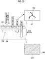
- the image obtained on the basis of the reflected light of violet light V and blue light B is referred to as a violet light image VP.
- green light G and red light R of the first illumination light beam reach the background mucous membrane BM that is distributed at a position deeper than the superficial blood vessels VS1 and deep blood vessels VS2 (blood vessels located at positions deeper than the superficial blood vessels VS1).
- a green and red light image GRP obtained on the basis of the reflected light of green light G and red light R includes an image of the background mucous membrane BM.
- the first image is an image in which the violet light image VP and the green and red light image GRP are combined with each other, the images of the background mucous membrane BM and the superficial blood vessels VS1 are displayed.
- the image storage unit 56 performs image storage processing.
- the image storage processing is processing of storing an image, for example, processing of storing the first image and the second image.
- the image storage control unit 61 controls the image storage processing. Specifically, the image storage control unit 61 performs control to select at least one first image and at least one second image that satisfy a preset selection condition from a plurality of types of images acquired in a predetermined period prior to a time of the processing start operation, for example, from a plurality of the first images and a plurality of the second images, to store the at least one first image and the at least one second image in the image storage unit 56, in a case where the processing start operation for starting the image storage processing is performed.
- the image signal acquisition unit 51 acquires the plurality of first images obtained by imaging the observation target illuminated with the first illumination light beam, in a period 91, and acquires the plurality of second images obtained by imaging the observation target illuminated with the second illumination light beam, in a period 92.
- a known method can be used as a method of selecting the first image and the second image having the least blur in the first images or the second images. For example, it is possible to select an image with the smallest amount of blur by calculating the amount of blur in each image.
- a method based on image analysis, a method based on the image pickup sensor 45, or the like is mainly used as a method of calculating the amount of blur, and there is a method of estimating a point spread function (PSF) for each of a plurality of regions in an image and of estimating the direction and magnitude of blur from the point spread function with high accuracy, as the method based on image analysis (see JP5499050B ).
- PSF point spread function
- the display control unit 57 performs control so as to display the still images in a display method set according to the purpose.
- the display method include a method of displaying the still images side by side on the display 18, a method of adjusting the transparency of each image to superimpose and display the still images, or a method of switching between the still images in a short time of 1 second or less on the same region of the display 18 to display the still images like an animation.
- a known method can be used.
- Examples of the method based on image analysis include a method of dividing the first image and the second image and comparing and obtaining the cumulative amounts of the Gs1 image signals of the first image and the Gs2 image signals of the second image having similar signal characteristics in respective regions.
- the display control unit 57 continuously displays the first image on the display 18 in the first period 75, and continuously displays the second image on the display 18 in the second period 76.
- step ST140 At least one first image and at least one second image that satisfy the preset selection condition are selected (step ST140) from the plurality of first images and the plurality of second images, which are acquired by the image signal acquisition unit 51 in the predetermined period prior to the time of the still image acquisition instruction, because the still image acquisition instruction corresponds to the processing start operation of the image storage processing.
- NO in step ST130 the observation and the acquisition of the first image and the second image are continued.
- the selected first and second images are stored by the image storage unit 56 (step ST150).
- the display control unit 57 displays the stored first and second images on the display 18 (step ST160).
- the present invention is applied to the endoscope system that performs processing on the endoscopic image, but the present invention can also be applied to a medical image processing system that processes medical images other than the endoscopic image, in a case where the still image is stored.
- the hardware structures of the light source processor 21, the image pickup processor, and the processing units that execute various types of processing are various processors to be described below.
Landscapes
- Health & Medical Sciences (AREA)
- Life Sciences & Earth Sciences (AREA)
- Surgery (AREA)
- Engineering & Computer Science (AREA)
- Physics & Mathematics (AREA)
- Optics & Photonics (AREA)
- Biomedical Technology (AREA)
- Molecular Biology (AREA)
- Pathology (AREA)
- Nuclear Medicine, Radiotherapy & Molecular Imaging (AREA)
- Biophysics (AREA)
- Heart & Thoracic Surgery (AREA)
- Medical Informatics (AREA)
- Radiology & Medical Imaging (AREA)
- Animal Behavior & Ethology (AREA)
- General Health & Medical Sciences (AREA)
- Public Health (AREA)
- Veterinary Medicine (AREA)
- Signal Processing (AREA)
- Microelectronics & Electronic Packaging (AREA)
- Endoscopes (AREA)
Abstract
Description
- The present invention relates to an endoscope system that stores a plurality of types of still images through an instruction, and a method of operating the endoscope system.
- In the medical field, a diagnosis using an endoscope system, which comprises a light source device, an endoscope, and a processor device, has been widely performed. In the diagnosis using the endoscope system, various types of information regarding a surface structure of an observation target, a mucous membrane surface layer, or the like may be obtained by using an image (hereinafter, referred to as an endoscopic image) obtained by imaging the observation target with the endoscope through image-enhanced observation (IEE, image enhanced endoscopy) in which an illumination light beam or the like is devised.
- In the diagnosis using IEE, an appropriate diagnosis may be made by acquiring a plurality of types of images obtained by a plurality of types of illumination light beams and the like, and comparing in detail or superimposing these images. As an endoscope system that uses a plurality of types of images including a normal image obtained through white light observation, an image obtained through IEE, and the like, an endoscope system that displays an oxygen saturation observation moving image, a normal observation moving image, and a blood vessel-enhanced observation moving image in parallel on a display device, and that sets an exposure condition and then stores each observation moving image as a still image in a case where a freeze button is operated while the moving images are displayed, and the like are disclosed (
JP2013-188364A - In the related art, a plurality of types of still images with less blur are selected and stored, for example, at a point in time back to the past by a certain period from a point in time when an instruction to store the still image is given by the operation of the freeze button while the moving image is displayed. In a plurality of illumination light beams, for example, two types of images are compared: an image using the illumination light beam that is used to enhance superficial blood vessels or the like of the observation target and an image using the illumination light beam that is used to enhance medium-depth blood vessels or the like of the same observation target so that information on the depth direction of the observation target can be obtained, which is effective, for example, in a case where a diagnosis on the extent of a lesion is performed.
- In order to store a plurality of types of still images corresponding to a plurality of illumination light beams, for example, as in the related art, the illumination light beams are switched and the still image is stored for each illumination light beam, whereby various still images are stored. In a case where an observation target is observed and an image thereof is picked up while the plurality of illumination light beams are repeatedly switched, it is preferable that the switching cycle between the illumination light beams used for observation is as long as possible due to problems, such as photosensitivity. However, in this case, it is necessary to select an image of an illumination light beam that is not used for observation when a still image acquisition instruction is given, and the longer the switching cycle between the illumination light beams is, the larger the difference in time between the plurality of types of stored images is. Since the larger the difference in time between the plurality of types of stored images is, the higher the probability that the positional deviation between the images may occur significantly is due to the motion of the observation target and the like, there is a concern that still images unsuitable for comparison or superimposition may be stored.
- On the other hand, in order to reduce the difference in time between the plurality of types of stored images, it is conceivable to reduce the switching cycle between the plurality of types of illumination light beams to shorten the illumination time of each illumination light beam. However, there is a concern that this method may cause problems, such as light flicker or photosensitivity, which is a trade-off with the difference in time between images.
- Further, in
JP2013-188364A - The present invention has been made in view of the above circumstances, and an object thereof is to provide an endoscope system that stores a plurality of types of still images in a state suitable for comparison or superimposition, through a single instruction, and a method of operating the endoscope system.
- The present invention relates to an endoscope system comprising a light source processor and an image processor. The light source processor is provided with a plurality of semiconductor light sources that emit light beams having wavelength bands different from each other, and performs control to switch a first illumination light beam to a second illumination light beam of which a combination of light intensity ratios between the plurality of semiconductor light sources is different from the first illumination light beam, to emit the second illumination light beam for a period of at least one frame, during a first period in which the first illumination light beam, out of a plurality of illumination light beams of which combinations of the light intensity ratios are different from each other, is emitted. The image processor acquires a first image or a second image obtained by imaging an observation target illuminated with the first illumination light beam or the second illumination light beam, for each frame, performs image storage processing of storing the first image and the second image, and selects and stores at least one first image and at least one second image that satisfy a preset selection condition, from a plurality of the first images and a plurality of the second images acquired in a preset period prior to a time of a processing start operation for starting the image storage processing, in a case where the processing start operation is performed.
- It is preferable that the selection condition is that a first image or a second image having least blur, out of the plurality of acquired first images and the plurality of acquired second images, is selected.
- It is preferable that the selection condition is that a first image and a second image having a smallest positional deviation between the first image and the second image selected from the plurality of acquired first images and the plurality of acquired second images are selected.
- It is preferable that the selection condition is that a first image and a second image having a smallest difference in acquisition time between the first image and the second image selected from the plurality of acquired first images and the plurality of acquired second images are selected.
- It is preferable that the light source processor alternately repeats the first period and a second period in which the second illumination light beam is emitted, and performs control to switch the second illumination light beam to the first illumination light beam to emit the first illumination light beam for a period of at least one frame during the period in which the second illumination light beam is emitted.
- It is preferable that the image processor performs control to display the acquired first image and/or the acquired second image, on a display, and displays at least the second image on the display during the second period.
- It is preferable that the image processor performs control to display the acquired first image and/or the acquired second image, on a display, and displays at least the first image on the display during the first period.
- It is preferable that the semiconductor light sources include a first semiconductor light source that emits a first narrow-band light beam having a wavelength band of which a central wavelength is 410±10 nm and a wavelength range is 420 to 500 nm, and a second semiconductor light source that emits a second narrow-band light beam having a wavelength band of which a central wavelength is 450±10 nm and a wavelength range is 380 to 420 nm.
- It is preferable that the image processor stores the first image and the second image after adding information regarding the illumination light beams used.
- Further, the present invention relates to a method of operating an endoscope system including a plurality of semiconductor light sources that emit light beams having wavelength bands different from each other, a light source processor, and an image processor. The method comprises performing, by the light source processor, control to switch a first illumination light beam to a second illumination light beam of which a combination of light intensity ratios between the plurality of semiconductor light sources is different from the first illumination light beam, to emit the second illumination light beam for a period of at least one frame, during a first period in which the first illumination light beam, out of a plurality of illumination light beams of which combinations of the light intensity ratios are different from each other, is emitted. The method comprises acquiring, by the image processor, a first image or a second image obtained by imaging an observation target illuminated with the first illumination light beam or the second illumination light beam, for each frame; performing, by the image processor, image storage processing of storing the first image and the second image; and selecting and storing, by the image processor, at least one first image and at least one second image that satisfy a preset selection condition, from a plurality of the first images and a plurality of the second images acquired in a preset period prior to a time of a processing start operation for starting the image storage processing, in a case where the processing start operation is performed.
- According to the present invention, it is possible to store a plurality of types of still images in a state suitable for comparison or superimposition, through a single instruction.
-
-
Fig. 1 is an external view of an endoscope system. -
Fig. 2 is an external view of an operation part of an endoscope. -
Fig. 3 is a block diagram showing a function of the endoscope system. -
Fig. 4 is a diagram illustrating four-color LEDs provided in a light source unit. -
Fig. 5 is a graph showing spectra of violet light V, blue light B, green light G, and red light R. -
Fig. 6 is a graph showing a spectrum of a first illumination light beam. -
Fig. 7 is a graph showing a spectrum of a second illumination light beam. -
Fig. 8 is a diagram illustrating an illumination light beam in a first special observation mode. -
Fig. 9 is a diagram illustrating an illumination light beam in a second special observation mode. -
Fig. 10 is a diagram illustrating an illumination light beam in a multi-observation mode. -
Fig. 11 is a diagram illustrating a light emission period setting menu. -
Fig. 12 is an image diagram showing a first special observation image. -
Fig. 13 is a diagram illustrating a violet and blue light image and a green and red light image that are obtained in a case where an observation target is illuminated with the first illumination light beam. -
Fig. 14 is an image diagram showing a second special observation image. -
Fig. 15 is a diagram illustrating a violet and blue light image and a green and red light image that are obtained in a case where an observation target is illuminated with the second illumination light beam. -
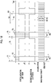
Fig. 16 is a diagram illustrating an example of storage of a still image in the first special observation mode. -
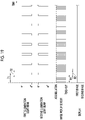
Fig. 17 is a diagram illustrating another example of the storage of the still image in the first special observation mode. -
Fig. 18 is a diagram illustrating an example of storage of a still image in the multi-observation mode. -
Fig. 19 is a diagram illustrating an image displayed on a display in the first special observation mode. -
Fig. 20 is a diagram illustrating an image displayed on the display in the multi-observation mode. -
Fig. 21 is a flowchart showing a series of flows of the storage of the still image in the first special observation mode. - In
Fig. 1 , anendoscope system 10 includes anendoscope 12, alight source device 14, aprocessor device 16, adisplay 18, and akeyboard 19. Theendoscope 12 is optically connected to thelight source device 14 and is electrically connected to theprocessor device 16. Theendoscope 12 includes aninsertion part 12a inserted into a body of an observation target, anoperation part 12b provided at the proximal end portion of theinsertion part 12a, and abendable portion 12c and adistal end portion 12d that are provided in theinsertion part 12a on the distal end side. Thebendable portion 12c is bent by the operation of anangle knob 12e (seeFig. 2 ) of theoperation part 12b. Thebendable portion 12c is bent so that thedistal end portion 12d faces a desired direction. - As shown in
Fig. 2 , theoperation part 12b includes amode changeover switch 12g used for an observation mode switching operation, azoom operation portion 12h that is used to change an image pickup magnification, and a still imageacquisition instruction portion 12f through which a still image acquisition instruction is given, in addition to theangle knob 12e. An operation or an instruction using thekeyboard 19, a foot switch (not shown), or the like, in addition to themode changeover switch 12g or a scope switch of the still imageacquisition instruction portion 12f, may be used for the observation mode switching operation, the zoom operation, or the still image acquisition instruction. - The
endoscope system 10 has three modes, that is, a normal observation mode, a special observation mode, and a multi-observation mode. The normal observation mode is a mode for displaying a normal observation image (hereinafter, referred to as a normal image), which is an image with natural color tones obtained by picking up an image of the observation target using white light as an illumination light beam, on thedisplay 18. The special observation mode includes a first special observation mode and a second special observation mode. The first special observation mode is a mode for displaying a first special observation image (hereinafter, referred to as a first image) in which surface layer information such as a superficial blood vessel is enhanced, on thedisplay 18, and the second special observation mode is a mode for displaying a second special observation image (hereinafter, referred to as a second image) in which deep layer information such as a deep blood vessel is enhanced, on thedisplay 18. The multi-observation mode is a mode for automatically switching between the first special observation mode and the second special observation mode. - The
processor device 16 is electrically connected to thedisplay 18 and thekeyboard 19. Thedisplay 18 outputs and displays, for example, the normal image, the first image, the second image, and/or accessory information on these images. Thekeyboard 19 functions as a user interface that receives an input operation, such as function settings. An external recording unit (not shown) that records images, image information, or the like may be connected to theprocessor device 16. - In
Fig. 3 , thelight source device 14 is a device that emits illumination light beams with which the observation target is irradiated, and comprises alight source unit 20 and alight source processor 21 that controls thelight source unit 20. Thelight source unit 20 is composed of, for example, a semiconductor light source, such as a multi-color light emitting diode (LED), a combination of a laser diode and a phosphor, or a xenon lamp or halogen light source. In addition, thelight source unit 20 includes, for example, an optical filter that is used to adjust the wavelength band of a light beam emitted by the LED or the like. Thelight source processor 21 turns on/off each LED or the like or adjusts the drive current and drive voltage of each LED or the like, thereby controlling the amount of the illumination light beam. Further, thelight source processor 21 controls the wavelength band of the illumination light beam by changing the optical filter or the like. - As shown in
Fig. 4 , in the present embodiment, thelight source unit 20 has four-color LEDs, that is, a violet light emitting diode (V-LED) 20a, a blue light emitting diode (B-LED) 20b, a green light emitting diode (G-LED) 20c, and a red light emitting diode (R-LED) 20d. - As shown in
Fig. 5 , the V-LED 20a generates violet light V having a central wavelength of 410±10 nm and a wavelength range of 380 to 420 nm. The B-LED 20b generates blue light B having a central wavelength of 450±10 nm and a wavelength range of 420 to 500 nm. The G-LED 20c generates green light G having a wavelength range of 480 to 600 nm. The R-LED 20d generates red light R having a central wavelength of 620 to 630 nm and a wavelength range of 600 to 650 nm. In the present specification, the term "to" between numerical values indicates a range including the numerical values before and after, and for example, "420 to 500 nm" means "420 nm or more and 500 nm or less". - The
light source processor 21 controls the V-LED 20a, the B-LED 20b, the G-LED 20c, and the R-LED 20d. Thelight source processor 21 controls therespective LEDs 20a to 20d such that a normal light beam of which the combination of light intensity ratios between violet light V, blue light B, green light G, and red light R is Vc:Bc:Gc:Rc is emitted in the normal observation mode. - The
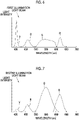
light source processor 21 controls therespective LEDs 20a to 20d such that a first illumination light beam of which the combination of the light intensity ratios between violet light V, blue light B, green light G, and red light R is Vs1:Bs1:Gs1:Rs1 is emitted in the first special observation mode. It is preferable that the first illumination light beam enhances superficial blood vessels. For this purpose, it is preferable that the light intensity of violet light V of the first illumination light beam is set to be higher than the light intensity of blue light B. For example, as shown inFig. 6 , a ratio of the light intensity Vs1 of violet light V to the light intensity Bs1 of blue light B is set to "4:1". - In the present specification, the combination of the light intensity ratios includes a case where the ratio of at least one semiconductor light source is zero. Therefore, the combination of the light intensity ratios includes a case where any one or two or more of the semiconductor light sources are not turned on. For example, a case where only one semiconductor light source is turned on and the other three semiconductor light sources are not turned on as in a case where the combination of the light intensity ratios between violet light V, blue light B, green light G, and red light R is 1:0:0:0 is also regarded that the
light source unit 20 has light intensity ratios, and is one of the combinations of the light intensity ratios. - Further, the
light source processor 21 controls therespective LEDs 20a to 20d such that a second illumination light beam of which the combination of the light intensity ratios between violet light V, blue light B, green light G, and red light R is Vs2:Bs2:Gs2:Rs2 is emitted in the second special observation mode. It is preferable that the second illumination light beam enhances deep blood vessels. For this purpose, it is preferable that the light intensity of blue light B of the second illumination light beam is set to be higher than the light intensity of the violet light V. For example, as shown inFig. 7 , a ratio of the light intensity Vs2 of violet light V to the light intensity Bs2 of blue light B is set to "1:3". - In the normal observation mode, the first special observation mode, or the second special observation mode, the combinations of the light intensity ratios between violet light V, blue light B, green light G, and red light R, that is, the types of the illumination light beam, are different from each other. The
light source processor 21 performs control to switch the first illumination light beam to an illumination light beam of which a combination of the light intensity ratios is different from the first illumination light beam, for example, the second illumination light beam, to emit the second illumination light beam for a period of at least one frame, during a first period in which a specific type of illumination light beam, for example, the first illumination light beam is emitted. Thelight source processor 21 performs control to switch the second illumination light beam to an illumination light beam of which a combination of the light intensity ratios is different from the second illumination light beam, for example, the first illumination light beam, to emit the first illumination light beam for a period of at least one frame, during a second period in which the second illumination light beam is emitted. In a case where thelight source processor 21 switches a specific type of illumination light beam to the other type of illumination light beam to emit the other type of illumination light beam, during a period in which the specific type of illumination light beam is emitted, the specific type of illumination light beam may be switched to the other type of illumination light beam at any time in point within the period of at least one frame, but control may be performed such that the other type of illumination light beam is periodically emitted in a preset cycle. Since the period during which the specific type of illumination light beam is emitted is a period during which the specific type of illumination light beam is continuously emitted, the specific type of illumination light beam may be emitted again, after the specific type of illumination light beam is switched to the other type of illumination light beam and the other type of illumination light beam is emitted during the period in which the specific type of illumination light beam is emitted. - "Frame" means a unit that is used to control an image pickup sensor 45 (see
Fig. 3 ) that picks up the image of the observation target. For example, "one frame" means a period including at least an exposure period in which theimage pickup sensor 45 is exposed to light beams emitted from the observation target and a read-out period in which image signals are read out. In the present embodiment, the first period or the second period is defined so as to correspond to the "frame" that is a unit of image pickup. - The above-described light emission control in the first period or the second period performed by the
light source processor 21 in the special observation mode will be described in detail. As described inFig. 8 , the first illumination light beam is switched to the second illumination light beam and the second illumination light beam is emitted in a cycle of a second illuminationlight emission period 72 for one frame with respect to a first illuminationlight emission period 71 for five frames, during the first period in which the first illumination light beam is continuously emitted, and the cycle is repeated. Alternatively, as shown inFig. 9 , the second illumination light beam is switched to the first illumination light beam and the first illumination light beam is emitted in a cycle of a first illuminationlight emission period 74 for one frame with respect to a second illuminationlight emission period 73 for five frames, during the second period in which the second illumination light beam is continuously emitted, and the cycle is repeated. In the figure, in order to avoid complicating the figure, only a part thereof is given a reference numeral. - The
light source processor 21 alternately repeats specific types of illumination light beams, for example, the first period in which the first illumination light beam is continuously emitted and the second period in which the second illumination light beam is emitted, in a case where the multi-observation mode is set. In the multi-observation mode, for example, thelight source processor 21 performs control to switch the first illumination light beam to the second illumination light beam to emit the second illumination light beam for a period of at least one frame, during the first period, and performs control to switch the second illumination light beam to the first illumination light beam to emit the first illumination light beam for a period of at least one frame, during the second period. - The light emission control in the multi-observation mode performed by the
light source processor 21 will be described in detail. As shown inFig. 10 , the first illumination light beam is switched to the second illumination light beam and the second illumination light beam is emitted in a cycle of the second illuminationlight emission period 72 for one frame with respect to the first illuminationlight emission period 71 for five frames, in afirst period 75 in which the first illumination light beam is continuously emitted, and the cycle is repeated during thefirst period 75. After that, the second illumination light beam is switched to the first illumination light beam and the first illumination light beam is emitted in a cycle of the first illuminationlight emission period 74 for one frame with respect to the second illuminationlight emission period 73 for five frames, in asecond period 76 in which the second illumination light beam is continuously emitted, and the cycle is repeated during thesecond period 76. After that, the period returns to thefirst period 75 in which the first illumination light beam is continuously emitted, and thefirst period 75 and thesecond period 76 are alternately repeated. In the present embodiment, thefirst period 75 and thesecond period 76 each correspond to 20 frames. - The first period that is the light emission period of the first illumination light beam and the second period that is the light emission period of the second illumination light beam can be appropriately changed by the light emission
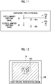
period setting unit 22 that is connected to thelight source processor 21. In a case where an operation for changing the light emission period is received by the operation of thekeyboard 19, the light emissionperiod setting unit 22 displays a light emission period setting menu shown inFig. 11 on thedisplay 18. The first period can be changed, for example, between 2 frames and 60 frames, and the respective light emission periods are assigned on aslide bar 81a. The second period can be also changed, for example, between 2 frames and 60 frames, and the respective light emission periods are assigned on aslide bar 81b. - In a case of changing the first period, a slider 82a is positioned, through the operation of the
keyboard 19, at a position on theslide bar 81a indicating a light emission period to be changed, whereby the first period is changed. Also in the second period, a slider 82b is positioned, through the operation of thekeyboard 19, at a position on theslide bar 81b indicating a light emission period to be changed, whereby the second period is changed. Theslide bar 81b is also assigned the light emission periods, for example, from 2 frames to 60 frames. In the present embodiment, in the multi-observation mode, the first period is assigned the light emission period for 20 frames through theslide bar 81a, and the second period is assigned the light emission period for 20 frames through theslide bar 81b. - A light beam emitted from each of the
LEDs 20a to 20e is incident on alight guide 41 through an optical path coupling unit (not shown) that is composed of a mirror, a lens, or the like. Thelight guide 41 is incorporated in theendoscope 12 and a universal cord (a cord that connects theendoscope 12 to thelight source device 14 and the processor device 16). Thelight guide 41 propagates the light beam from the optical path coupling unit to thedistal end portion 12d of theendoscope 12. - The
distal end portion 12d of theendoscope 12 is provided with an illuminationoptical system 30a and an image pickupoptical system 30b. The illuminationoptical system 30a has anillumination lens 42, and the observation target is irradiated with the illumination light beam propagated by thelight guide 41, through theillumination lens 42. The image pickupoptical system 30b has anobjective lens 43, azoom lens 44, and animage pickup sensor 45. Various types of light beams, such as light reflected from the observation target, scattered light, and fluorescence, are incident on theimage pickup sensor 45 through theobjective lens 43 and thezoom lens 44. With this, the image of the observation target is formed on theimage pickup sensor 45. Thezoom lens 44 is freely moved between the telephoto end and the wide end by the operation of thezoom operation portion 12h, and magnifies and reduces the observation target of which the image is formed on theimage pickup sensor 45. - The
image pickup sensor 45 is a color image pickup sensor provided with any one of a red (R) color filter, a green (G) color filter, or a blue (B) color filter for each pixel, and picks up the image of the observation target to output image signals of respective RGB colors. A charge coupled device (CCD) image pickup sensor or a complementary metal-oxide semiconductor (CMOS) image pickup sensor can be used as theimage pickup sensor 45. Alternatively, a complementary color image pickup sensor provided with color filters of complementary colors, that is, cyan (C), magenta (M), yellow (Y), and green (G), may be used instead of theimage pickup sensor 45 provided with color filters of the primary colors. In a case where the complementary color image pickup sensor is used, the image signals of four colors of CMYG are output. Therefore, the same RGB image signals as those of theimage pickup sensor 45 can be obtained by converting the image signals of the four colors of CMYG into the image signals of the three colors of RGB through the complementary color-primary color conversion. Alternatively, a monochrome image pickup sensor that is not provided with color filters may be used instead of theimage pickup sensor 45. - The
image pickup sensor 45 is driven and controlled by an image pickup processor (not shown). The control performed by the image pickup processor differs depending on the respective modes. In the normal observation mode, the image pickup processor controls theimage pickup sensor 45 to pick up the image of the observation target illuminated with a normal light beam. With this, Bc image signals are output from B pixels of theimage pickup sensor 45, Gc image signals are output from G pixels thereof, and Rc image signals are output from R pixels thereof. In the special observation mode or the multi-observation mode, the image pickup processor controls theimage pickup sensor 45 to pick up the image of the observation target illuminated with a special light beam. With this, in the first special observation mode, Bs1 image signals are output from the B pixels of theimage pickup sensor 45, Gs1 image signals are output from the G pixels thereof, and Rs1 image signals are output from the R pixels thereof. Similarly, in the second special observation mode, Bs2 image signals are output from the B pixels of theimage pickup sensor 45, Gs2 image signals are output from the G pixels thereof, and Rs2 image signals are output from the R pixels thereof. - A correlated double sampling/automatic gain control (CDS/AGC)
circuit 46 performs correlated double sampling (CDS) or automatic gain control (AGC) on the analog image signals obtained from theimage pickup sensor 45. The image signals that have been passed through the CDS/AGC circuit 46 are converted into digital image signals by an analog/digital (A/D)converter 47. The digital image signals that have been subjected to A/D conversion are input to theprocessor device 16. - In the
processor device 16, a program related to processing such as image storage processing is stored in the program memory (not shown). In theprocessor device 16, the program stored in the program memory operates through acentral control unit 62 composed of the image processor, whereby functions of an imagesignal acquisition unit 51, a digital signal processor (DSP) 52, anoise reduction unit 53, amemory 54, asignal processing unit 55, animage storage unit 56, an imagestorage control unit 61, adisplay control unit 57, and a videosignal generation unit 58 are realized. Further, thecentral control unit 62 receives information input from theendoscope 12 and thelight source device 14, and controls each unit of theprocessor device 16 and controls theendoscope 12 or thelight source device 14, on the basis of the received information. Further, thecentral control unit 62 also receives information, such as an instruction input from thekeyboard 19. - The image
signal acquisition unit 51 acquires the digital image signals of an endoscopic image, which are input from theendoscope 12. The imagesignal acquisition unit 51 acquires image signals obtained by imaging the observation target illuminated with each illumination light beam, for each frame. The acquired image signals are transmitted to theDSP 52. TheDSP 52 performs various types of signal processing, such as offset processing, defect correction processing, demosaicing processing, linear matrix processing, gain correction processing, gamma conversion processing, and YC conversion processing, on the received image signals. In the offset processing, dark current components are removed from the received image signals, and an accurate zero level is set. In the defect correction processing, signals of defective pixels of theimage pickup sensor 45 are corrected. The demosaicing processing (also referred to as equalization processing or demosaicing) is performed on the image signals that have been subjected to the defect correction processing, and signals of lacking color in each pixel are generated by interpolation. All the pixels are made to have signals of the respective RGB colors through the demosaicing processing. - The linear matrix processing of improving color reproducibility is performed on the image signals of each color, which have been subjected to the demosaicing processing. In the gain correction processing, the image signals of each color, which have been subjected to the demosaicing processing, are multiplied by a specific gain, whereby the signal level of each image signal is adjusted. After that, the brightness or chroma saturation of each image signal is adjusted through the gamma conversion processing. The
DSP 52 performs the YC conversion processing on each image signal that has been subjected to the gamma conversion processing, and outputs brightness signals Y, color difference signals Cb, and color difference signals Cr to thenoise reduction unit 53. - The
noise reduction unit 53 performs noise reduction processing, which is performed through, for example, a moving average method or median filtering method, on the image signals that have been subjected to the gamma conversion processing and the like by theDSP 52. The image signals with reduced noise are stored in thememory 54. - The
signal processing unit 55 acquires the noise-reduced image signals from thememory 54. Then, signal processing, such as color conversion processing, hue enhancement processing, and structure enhancement processing, is performed as necessary on the acquired image signals, and a color endoscopic image in which the observation target is imaged is generated. The color conversion processing is processing of performing color conversion through 3 × 3 matrix processing, gradation transformation processing, three-dimensional look-up table (LUT) processing, and the like, on the image signals. The hue enhancement processing is performed on the image signals that have been subjected to the color conversion processing. The structure enhancement processing is processing of enhancing, for example, a specific tissue or structure included in the observation target, such as blood vessels or pit patterns, and is performed on the image signals that have been subjected to the hue enhancement processing. - In the normal observation mode, the
signal processing unit 55 performs image processing for a normal image on the input noise-reduced image signals for one frame. The image processing for a normal image includes color conversion processing, such as 3 × 3 matrix processing, gradation transformation processing, and three-dimensional LUT processing, hue enhancement processing, and structure enhancement processing, such as spatial frequency enhancement. The image signals that have been subjected to the image processing for a normal image are input to theimage storage unit 56, as a normal image. - In the special observation mode, the
signal processing unit 55 performs image processing for a special image on the noise-reduced image signals for one frame, which are input in the first special observation mode or the second special observation mode. The image processing for a special image includes color conversion processing, such as 3 × 3 matrix processing, gradation transformation processing, and three-dimensional LUT processing, hue enhancement processing, and structure enhancement processing, such as spatial frequency enhancement. The image signals that have been subjected to the image processing for a special image is input to theimage storage unit 56, as the first image or the second image. - Since the endoscopic image generated by the
signal processing unit 55 is a normal observation image in a case where the observation mode is the normal observation mode and is a special observation image in a case where the observation mode is the special observation mode, the contents of the color conversion processing, the hue enhancement processing, and the structure enhancement processing differ depending on the observation modes. In the normal observation mode, thesignal processing unit 55 generates the normal observation image by performing the above various types of signal processing of making the observation target have natural color tones. In the special observation mode, thesignal processing unit 55 generates the special observation image including the first image and the second image by performing the above various types of signal processing of enhancing, for example, the blood vessels of the observation target. - The semiconductor light sources include a first semiconductor light source that emits violet light V (first narrow-band light beam) having a wavelength band of which the central wavelength is 410±10 nm and the wavelength range is 420 to 500 nm, and a second semiconductor light source that emits blue light B (second narrow-band light beam) having a wavelength band of which the central wavelength is 450±10 nm and the wavelength range is 380 to 420 nm. Therefore, in the special observation image generated by the
signal processing unit 55, blood vessels (so-called superficial blood vessels) or blood located at a relatively shallow position in the observation target with a surface of the mucous membrane as a reference has magenta-based color (for example, brown color) in the first image, and blood vessels (so-called medium-depth blood vessels) located at a relatively deep position in the observation target with the surface of the mucous membrane as a reference have cyan-based color (for example, green color) in the second image. Therefore, the blood vessels or hemorrhage (blood) of the observation target is enhanced by a difference in color with respect to the mucous membrane represented by pink-based color. - As shown in
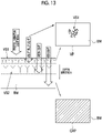
Fig. 12 , an image in which a background mucous membrane BM and superficial blood vessels VS1, out of the observation targets, are shown is displayed in the first image. The first image is obtained on the basis of the first illumination light beam including violet light, blue light, green light, and red light. As shown inFig. 13 , in a case where the observation target is illuminated with the first illumination light beam, violet light V and blue light B of the first illumination light beam reach a surface layer where the superficial blood vessels VS1 are distributed. Accordingly, a violet light image VP obtained on the basis of the reflected light of violet light V and blue light B includes an image of the superficial blood vessels VS1. Here, since the light intensity of violet light V is higher than the light intensity of blue light B, the image obtained on the basis of the reflected light of violet light V and blue light B is referred to as a violet light image VP. Further, green light G and red light R of the first illumination light beam reach the background mucous membrane BM that is distributed at a position deeper than the superficial blood vessels VS1 and deep blood vessels VS2 (blood vessels located at positions deeper than the superficial blood vessels VS1). Accordingly, a green and red light image GRP obtained on the basis of the reflected light of green light G and red light R includes an image of the background mucous membrane BM. As described above, since the first image is an image in which the violet light image VP and the green and red light image GRP are combined with each other, the images of the background mucous membrane BM and the superficial blood vessels VS1 are displayed. - As shown in
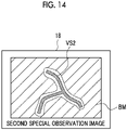
Fig. 14 , an image in which the background mucous membrane BM and the deep blood vessels VS2, out of the observation targets, are shown is displayed in the second image. The second image is obtained on the basis of the second illumination light beam including violet light, blue light, green light, and red light. As shown inFig. 15 , in a case where the observation target is illuminated with the second illumination light beam, violet light V and blue light B of the second illumination light beam reach a deep layer where the deep blood vessels VS2 are distributed. Accordingly, a blue light image BP obtained on the basis of the reflected light of violet light V and blue light B includes an image of the deep blood vessels VS2. Here, since the light intensity of blue light B is higher than the light intensity of violet light V, the image obtained on the basis of the reflected light of violet light V and blue light B is referred to as a blue light image BP. Further, green light G and red light R of the second illumination light beam reach the background mucous membrane BM that is distributed at a position deeper than the superficial blood vessels VS1 and the deep blood vessels VS2 (blood vessels located at positions deeper than the superficial blood vessels VS1). Accordingly, a green and red light image GRP obtained on the basis of the reflected light of green light G and red light R includes an image of the background mucous membrane BM. As described above, since the second image is an image in which the blue light image BP and the green and red light image GRP are combined with each other, the images of the background mucous membrane BM and the deep blood vessels VS2 are displayed. - The
image storage unit 56 performs image storage processing. The image storage processing is processing of storing an image, for example, processing of storing the first image and the second image. The imagestorage control unit 61 controls the image storage processing. Specifically, the imagestorage control unit 61 performs control to select at least one first image and at least one second image that satisfy a preset selection condition from a plurality of types of images acquired in a predetermined period prior to a time of the processing start operation, for example, from a plurality of the first images and a plurality of the second images, to store the at least one first image and the at least one second image in theimage storage unit 56, in a case where the processing start operation for starting the image storage processing is performed. - The processing start operation is, for example, a still image acquisition instruction (freeze instruction or release instruction) operation through the still image
acquisition instruction portion 12f. In a case where the still image acquisition instruction is input by the operation of the still imageacquisition instruction portion 12f, the processing start operation is performed and the image storage processing is started. Theimage storage unit 56 stores endoscopic images such as the first image and the second image selected by the preset selection condition in theimage storage unit 56 or a storage (not shown), under the control performed by the imagestorage control unit 61. The storage is an external storage device connected to theprocessor device 16 through a local area network (LAN) or the like, and is, for example, a file server of a system for filing an endoscopic image, such as a picture archiving and communication system (PACS), or a network attached storage (NAS). - As shown in
Fig. 16 , the image storage processing performed by the imagestorage control unit 61 is specifically performed as follows. In the first special observation mode, as the illumination light beam, the first illumination light beam is switched to the second illumination light beam and the second illumination light beam is emitted in a cycle of the second illuminationlight emission period 72 for one frame with respect to the first illuminationlight emission period 71 for five frames, during the first period in which the first illumination light beam is continuously emitted, and the cycle is repeated. Theimage pickup sensor 45 acquires image signals by performing charge accumulation and read-out for each frame. InFig. 16 , first image signal acquisition performed by theimage pickup sensor 45 is shown by a solid line, and second image signal acquisition is shown by a broken line. Further, since the figure is schematically shown, for example, the time for accumulation and read-out is not always the same. As described above, the imagesignal acquisition unit 51 acquires the plurality of first images obtained by imaging the observation target illuminated with the first illumination light beam, in aperiod 91, and acquires the plurality of second images obtained by imaging the observation target illuminated with the second illumination light beam, in aperiod 92. - In a case where a still
image acquisition instruction 93 is given, the imagestorage control unit 61 performs control to select at least one first image and at least one second image that satisfy the selection condition from the plurality of first images and the plurality of second images acquired in a presetpredetermined period 94, to store the at least one first image and the at least one second image in theimage storage unit 56. Although the selection condition can be set in advance, the selection condition is conditioned on storing the first image and the second image to be stored, in a state suitable for comparison or superimposition. For example, the imagestorage control unit 61 preferably sets the selection condition such that a first image and a second image having the least blur, out of the plurality of acquired first images and the plurality of acquired second images, are selected. - As a method of selecting the first image and the second image having the least blur in the first images or the second images, a known method can be used. For example, it is possible to select an image with the smallest amount of blur by calculating the amount of blur in each image. A method based on image analysis, a method based on the
image pickup sensor 45, or the like is mainly used as a method of calculating the amount of blur, and there is a method of estimating a point spread function (PSF) for each of a plurality of regions in an image and of estimating the direction and magnitude of blur from the point spread function with high accuracy, as the method based on image analysis (seeJP5499050B JP1991-16470A JP-H03-16470A - In
Fig. 16 , afirst image 96 and asecond image 95 having the least blur, out of the plurality of first images and the plurality of second images acquired in a period of thepredetermined period 94 from the stillimage acquisition instruction 93, are selected. Thefirst image 96 and thesecond image 95 selected by the imagestorage control unit 61 are stored in theimage storage unit 56 by the imagestorage control unit 61. Theimage storage unit 56 uses the image signals sent from thesignal processing unit 55 to perform image storage processing, and also sends the image signals to thedisplay control unit 57 for display. - The image acquired by the image
signal acquisition unit 51 or the image stored by theimage storage unit 56 has a time acquired as accessory information on the image, but it is preferable that theimage storage unit 56 stores the first image and the second image after adding information regarding the corresponding illumination light beams. In this case, it is preferable to have information on the illumination light beam or the observation mode, as the accessory information. Further, the file name of the image may be given, for example, identification information or an identifier associated with the illumination light beam or the observation mode, such as a tag. According to the above, it is possible to easily recognize whether the acquired or stored image is the first image or the second image. - The
display control unit 57 performs control to display the image on thedisplay 18, which is a display means. For example, thedisplay control unit 57 performs control to continuously display the normal image as a moving image on thedisplay 18 in the normal observation mode, to continuously display the first image or the second image as a moving image on thedisplay 18 in the special observation mode, and to automatically switch any one of the first image or the second image to continuously display the switched image as a moving image on thedisplay 18 in the multi-observation mode. In a case where the stillimage acquisition instruction 93 is given, thedisplay control unit 57 performs control to display the endoscopic images such as the first image and the second image selected by the selection condition as still images on thedisplay 18. - In a case where the still images such as the first image and the second image are displayed, the
display control unit 57 performs control so as to display the still images in a display method set according to the purpose. Examples of the display method include a method of displaying the still images side by side on thedisplay 18, a method of adjusting the transparency of each image to superimpose and display the still images, or a method of switching between the still images in a short time of 1 second or less on the same region of thedisplay 18 to display the still images like an animation. - The video
signal generation unit 58 converts, for example, the normal image and the special image, which are output from thedisplay control unit 57, the first image and the second image, which are stored in theimage storage unit 56, and/or the accessory information on these images into video signals that allow full-color display on thedisplay 18. The video signals that have been converted are input to thedisplay 18. With this, the normal image, the special image, the accessory information, or the like is displayed on thedisplay 18. - As described above, in the
endoscope system 10, while the illumination period of the illumination light beam used for observation is lengthened, the images are acquired by, for example, switching the illumination light beam to the other illumination light beam for a moment such as one frame, during the illumination period. Therefore, it is possible to easily acquire a plurality of types of images corresponding to a plurality of types of illumination light beams. Further, the switching of the illumination light beam is a momentary period such as one frame, and one type of illumination light beam is continuously emitted except for the momentary period, so that a user does not recognize the switching of the illumination and the problem of photosensitivity is less likely to occur. Accordingly, with theendoscope system 10 having the above configuration, it is possible to store a plurality of types of still images in a state suitable for comparison or superimposition, through the single stillimage acquisition instruction 93. - The image
storage control unit 61 preferably sets the selection condition such that a first image and a second image having the smallest positional deviation between the first image and the second image selected from the plurality of acquired first images and the plurality of acquired second images are selected. The positional deviation between the selected first and second images is small, so that it is possible to store the first image and the second image in a state suitable for comparison or superimposition. - As a method of selecting the first image and the second image having the smallest positional deviation therebetween, a known method can be used. Examples of the method based on image analysis include a method of dividing the first image and the second image and comparing and obtaining the cumulative amounts of the Gs1 image signals of the first image and the Gs2 image signals of the second image having similar signal characteristics in respective regions.
- Further, the image
storage control unit 61 preferably sets the selection condition such that a first image and a second image having a smallest difference in acquisition time between the first image and the second image selected from the plurality of acquired first images and the plurality of acquired second images are selected. The smaller the difference in acquisition time between the selected first and second images is, the less likely it is that the positional deviation between the first image and the second image occurs, so that it is possible to store the first image and the second image in a state suitable for comparison or superimposition. - As shown in
Fig. 17 , in a case where the plurality of first images are acquired in theperiod 91 and the plurality of second images are acquired in theperiod 92 by the same illumination light beams,image pickup sensor 45, imagesignal acquisition unit 51 as inFig. 16 , thefirst image 96 and thesecond image 95 close to the time of the stillimage acquisition instruction 93, out of the first images and the second images having the smallest difference in acquisition time therebetween, are selected. Thefirst image 96 and thesecond image 95 selected by the imagestorage control unit 61 are stored in theimage storage unit 56 by the imagestorage control unit 61. - The selection condition as described above may be used alone or in combination of two or more. For example, in a case where there are a plurality of combinations of the first image and the second image having the smallest difference in acquisition time therebetween, images with less blur may be selected.
- In the multi-observation mode, the image storage processing performed by the image
storage control unit 61 is specifically performed as shown inFig. 18 . The illumination light beam is the illumination light beam in the multi-observation mode. In the figure, the same reference numeral indicates the same element. Therefore, inFig. 18 , the same reference numerals as those inFig. 10 indicate the same elements. Theimage pickup sensor 45 acquires image signals by performing charge accumulation and read-out for each frame. InFig. 18 , the first image signal acquisition performed by theimage pickup sensor 45 is shown by a solid line, and the second image signal acquisition is shown by a broken line. Therefore, the imagesignal acquisition unit 51 acquires the plurality of first images obtained by imaging the observation target illuminated with the first illumination light beam, in theperiod 91, and acquires the plurality of second images obtained by imaging the observation target illuminated with the second illumination light beam, in theperiod 92, and acquires the plurality of second images obtained by imaging the observation target illuminated with the second illumination light beam, in theperiod 97, and acquires the plurality of second images obtained by imaging the observation target illuminated with the first illumination light beam, in theperiod 98. - In a case where the still
image acquisition instruction 93 is given, the imagestorage control unit 61 performs control to select at least one first image and at least one second image that satisfy the selection condition from the plurality of first images and the plurality of second images acquired in a presetpredetermined period 94, to store the at least one first image and the at least one second image in theimage storage unit 56. The selection condition and the like are the same as in the case of the special observation mode described above. - As described above, with the
endoscope system 10, it is also possible to store a plurality of types of still images in a state suitable for comparison or superimposition, through the single stillimage acquisition instruction 93, in the multi-observation mode. - The
display control unit 57 may perform control to continuously display the first image on thedisplay 18 during the first period. During the first period, the first illumination light beam is switched to the second illumination light beam and the second illumination light beam is emitted for a period of at least one frame, and theimage pickup sensor 45 acquires image signals for each frame, but thedisplay 18 continuously displays the first image. - As shown in
Fig. 19 , in the first special observation mode, the imagesignal acquisition unit 51 acquires the plurality of first images obtained by imaging the observation target illuminated with the first illumination light beam, in aperiod 91, and acquires the plurality of second images obtained by imaging the observation target illuminated with the second illumination light beam, in aperiod 92. Thedisplay control unit 57 performs control to display the acquired image on thedisplay 18, and performs control not to display the acquired second image on thedisplay 18 in the present embodiment. In this case, the display period of the first image immediately before the acquisition of the second image may be extended as it is, during the period in which the second image is acquired. Similarly, in the second special observation mode, the second image is continuously displayed. - In the multi-observation mode, as shown in
Fig. 20 , thedisplay control unit 57 continuously displays the first image on thedisplay 18 in thefirst period 75, and continuously displays the second image on thedisplay 18 in thesecond period 76. - As described above, the
display control unit 57 performs control to continuously display the first image on thedisplay 18 during the first period, so that it is possible to display the endoscopic images on thedisplay 18 without flicker or the like while acquiring image signals having a mode different from the mode being observed. Accordingly, the user can perform observation and the like more stably. - Next, a series of flows of still image storage will be described with reference to the flowchart shown in
Fig. 21 . In the case of the first special observation mode, observation is performed in the first special observation mode (step ST110). During the observation, the imagesignal acquisition unit 51 acquires the first image and the second image (step ST120). In this case, as the endoscopic image displayed on thedisplay 18, the first image may be continuously displayed, or the display may be switched between the first image and the second image in accordance with the acquisition of the image. - In a case where there is the still image acquisition instruction (YES in step ST130), at least one first image and at least one second image that satisfy the preset selection condition are selected (step ST140) from the plurality of first images and the plurality of second images, which are acquired by the image
signal acquisition unit 51 in the predetermined period prior to the time of the still image acquisition instruction, because the still image acquisition instruction corresponds to the processing start operation of the image storage processing. In a case where there is no still image acquisition instruction (NO in step ST130), the observation and the acquisition of the first image and the second image are continued. The selected first and second images are stored by the image storage unit 56 (step ST150). Thedisplay control unit 57 displays the stored first and second images on the display 18 (step ST160). The display format is a preset format, and for example, two images are superimposed and displayed on thedisplay 18. In a case where the observation is completed (YES in step ST170), a series of flows ends. In a case where the observation is continued (NO in step ST170), the process returns to the observation in the first special mode. - In the above embodiment, the present invention is applied to the endoscope system that performs processing on the endoscopic image, but the present invention can also be applied to a medical image processing system that processes medical images other than the endoscopic image, in a case where the still image is stored.
- In the above embodiment, the hardware structures of the
light source processor 21, the image pickup processor, and the processing units that execute various types of processing, such as thecentral control unit 62, the imagesignal acquisition unit 51, theDSP 52, thenoise reduction unit 53, thememory 54, thesignal processing unit 55, theimage storage unit 56, the imagestorage control unit 61, thedisplay control unit 57, and the videosignal generation unit 58, which are included in theprocessor device 16, are various processors to be described below. The various processors include, for example, a central processing unit (CPU) which is a general-purpose processor that executes software (programs) to function as various processing units, a programmable logic device (PLD) which is a processor having a changeable circuit configuration after manufacture, such as a field programmable gate array (FPGA), and a dedicated electrical circuit which is a processor having a dedicated circuit configuration designed to execute various processing. - One processing unit may be composed of one of these various processors or a combination of two or more of the processors of the same type or different types (for example, a plurality of FPGAs, or a combination of a CPU and an FPGA). Alternatively, a plurality of processing units may be composed of one processor. A first example in which a plurality of processing units are composed of one processor is an aspect in which one or more CPUs and software are combined to constitute one processor and the processor functions as a plurality of processing units, as typified by a computer such as a client or a server. A second example is an aspect in which a processor that realizes all of the functions of a system including a plurality of processing units with one integrated circuit (IC) chip is used, as typified by a system on chip (SoC) or the like. As described above, various processing units may be formed of one or more of the above various processors as hardware structures.
- More specifically, the hardware structure of these various processors is an electrical circuit (circuitry) in which circuit elements, such as semiconductor elements, are combined.
-
- 10: endoscope system
- 12: endoscope
- 12a: insertion part
- 12b: operation part
- 12c: bendable portion
- 12d: distal end portion
- 12e: angle knob
- 12f: still image acquisition instruction portion
- 12g: mode changeover switch
- 12h: zoom operation portion
- 14: light source device
- 16: processor device
- 18: display
- 19: keyboard
- 20: light source unit
- 20a: V-LED
- 20b: B-LED
- 20c: G-LED
- 20d: R-LED
- 21: light source processor
- 22: light emission period setting unit
- 30a: illumination optical system
- 30b: image pickup optical system
- 41: light guide
- 42: illumination lens
- 43: objective lens
- 44: zoom lens
- 45: image pickup sensor
- 46: CDS/AGC circuit
- 47: A/D converter
- 51: image signal acquisition unit
- 52: DSP
- 53: noise reduction unit
- 54: memory
- 55: signal processing unit
- 56: image storage unit
- 57: display control unit
- 58: video signal generation unit
- 61: image storage control unit
- 62: central control unit
- 71, 74: first illumination light emission period
- 72, 73: second illumination light emission period
- 81a, 81b: slide bar
- 82a, 82b: slider
- 91, 92, 97, 98: period
- 93: still image acquisition instruction
- 94: predetermined period
- 95: second image
- 96: first image
- BM: background mucous membrane
- VS1: superficial blood vessel
- VS2: deep blood vessel
- VP: violet light image
- GRP: green and red light image
- ST110 to ST200: step
Claims (10)
- An endoscope system comprising:a plurality of semiconductor light sources that emit light beams having wavelength bands different from each other;a light source processor that performs control to switch a first illumination light beam to a second illumination light beam of which a combination of light intensity ratios between the plurality of semiconductor light sources is different from the first illumination light beam, to emit the second illumination light beam for a period of at least one frame, during a first period in which the first illumination light beam, out of a plurality of illumination light beams of which combinations of the light intensity ratios are different from each other, is emitted; andan image processor,wherein the image processoracquires a first image or a second image obtained by imaging an observation target illuminated with the first illumination light beam or the second illumination light beam, for each frame,performs image storage processing of storing the first image and the second image, andselects and stores at least one first image and at least one second image that satisfy a preset selection condition, from a plurality of the first images and a plurality of the second images acquired in a preset period prior to a time of a processing start operation for starting the image storage processing, in a case where the processing start operation is performed.
- The endoscope system according to claim 1,
wherein the selection condition is that a first image and a second image having least blur, out of the plurality of acquired first images and the plurality of acquired second images, are selected. - The endoscope system according to claim 1 or 2,
wherein the selection condition is that a first image and a second image having a smallest positional deviation between the first image and the second image selected from the plurality of acquired first images and the plurality of acquired second images are selected. - The endoscope system according to any one of claims 1 to 3,
wherein the selection condition is that a first image and a second image having a smallest difference in acquisition time between the first image and the second image selected from the plurality of acquired first images and the plurality of acquired second images are selected. - The endoscope system according to any one of claims 1 to 4,
wherein the light source processor alternately repeats the first period and a second period in which the second illumination light beam is emitted, and performs control to switch the second illumination light beam to the first illumination light beam to emit the first illumination light beam for a period of at least one frame during the second period. - The endoscope system according to claim 5,
wherein the image processor performs control to display the acquired first image and/or the acquired second image, on a display, and
displays at least the second image on the display during the second period. - The endoscope system according to any one of claims 1 to 5,
wherein the image processor performs control to display the acquired first image and/or the acquired second image, on a display, and
displays at least the first image on the display during the first period. - The endoscope system according to any one of claims 1 to 7,
wherein the semiconductor light sources include a first semiconductor light source that emits a first narrow-band light beam having a wavelength band of which a central wavelength is 410±10 nm and a wavelength range is 420 to 500 nm, and a second semiconductor light source that emits a second narrow-band light beam having a wavelength band of which a central wavelength is 450±10 nm and a wavelength range is 380 to 420 nm. - The endoscope system according to any one of claims 1 to 8,
wherein the image processor stores the first image and the second image after adding information regarding the illumination light beams used. - A method of operating an endoscope system including a plurality of semiconductor light sources that emit light beams having wavelength bands different from each other,a light source processor, andan image processor, the method comprising:performing, by the light source processor, control to switch a first illumination light beam to a second illumination light beam of which a combination of light intensity ratios between the plurality of semiconductor light sources is different from the first illumination light beam, to emit the second illumination light beam for a period of at least one frame, during a first period in which the first illumination light beam, out of a plurality of illumination light beams of which combinations of the light intensity ratios are different from each other, is emitted; andacquiring, by the image processor, a first image or a second image obtained by imaging an observation target illuminated with the first illumination light beam or the second illumination light beam, for each frame;performing, by the image processor, image storage processing of storing the first image and the second image; andselecting and storing, by the image processor, at least one first image and at least one second image that satisfy a preset selection condition, from a plurality of the first images and a plurality of the second images acquired in a preset period prior to a time of a processing start operation for starting the image storage processing, in a case where the processing start operation is performed.
Applications Claiming Priority (2)
| Application Number | Priority Date | Filing Date | Title |
|---|---|---|---|
| JP2020034275 | 2020-02-28 | ||
| PCT/JP2021/005937 WO2021172131A1 (en) | 2020-02-28 | 2021-02-17 | Endoscope system and endoscope system operation method |
Publications (3)
| Publication Number | Publication Date |
|---|---|
| EP4111936A1 true EP4111936A1 (en) | 2023-01-04 |
| EP4111936A4 EP4111936A4 (en) | 2023-08-09 |
| EP4111936B1 EP4111936B1 (en) | 2025-12-31 |
Family
ID=77490980
Family Applications (1)
| Application Number | Title | Priority Date | Filing Date |
|---|---|---|---|
| EP21761328.0A Active EP4111936B1 (en) | 2020-02-28 | 2021-02-17 | ENDOSCOPE SYSTEM AND ENDOSCOPE SYSTEM OPERATING PROCEDURES |
Country Status (5)
| Country | Link |
|---|---|
| US (1) | US12318071B2 (en) |
| EP (1) | EP4111936B1 (en) |
| JP (1) | JP7390465B2 (en) |
| CN (1) | CN115209778B (en) |
| WO (1) | WO2021172131A1 (en) |
Families Citing this family (1)
| Publication number | Priority date | Publication date | Assignee | Title |
|---|---|---|---|---|
| US20240099554A1 (en) * | 2022-09-28 | 2024-03-28 | Boston Scientific Scimed, Inc. | Medical devices and related systems and methods for automatic image brightness control |
Family Cites Families (29)
| Publication number | Priority date | Publication date | Assignee | Title |
|---|---|---|---|---|
| JPH0316470A (en) | 1989-06-14 | 1991-01-24 | Matsushita Electric Ind Co Ltd | Hand blur correction device |
| US5896166A (en) * | 1993-06-02 | 1999-04-20 | Envision Medical Corporation | Remote CCD video camera with non-volatile digital memory |
| US20090289200A1 (en) | 2008-05-22 | 2009-11-26 | Fujifilm Corporation | Fluorescent image obtainment method and apparatus, fluorescence endoscope, and excitation-light unit |
| JP5110702B2 (en) * | 2008-05-22 | 2012-12-26 | 富士フイルム株式会社 | Fluorescence image acquisition device |
| JP2010279454A (en) | 2009-06-03 | 2010-12-16 | Olympus Corp | Image processor, image processing method, image processing program, and imaging device |
| JP5499050B2 (en) | 2009-12-22 | 2014-05-21 | パナソニック株式会社 | Image processing apparatus, imaging apparatus, and image processing method |
| EP2579570B1 (en) * | 2010-06-07 | 2017-01-04 | Olympus Corporation | Signal processing device and still image generation method |
| JP5841353B2 (en) * | 2011-05-24 | 2016-01-13 | オリンパス株式会社 | Endoscope apparatus and image acquisition method |
| EP2668891B1 (en) * | 2011-10-27 | 2019-02-06 | Olympus Corporation | Endoscope system |
| EP2679143B1 (en) * | 2011-11-11 | 2017-09-27 | Olympus Corporation | Wireless image transmission system |
| JP5587932B2 (en) | 2012-03-14 | 2014-09-10 | 富士フイルム株式会社 | Endoscope system, processor device for endoscope system, and method for operating endoscope system |
| JP5735479B2 (en) * | 2012-12-14 | 2015-06-17 | 富士フイルム株式会社 | Endoscope and device operation method |
| JP2014220690A (en) * | 2013-05-09 | 2014-11-20 | オリンパスメディカルシステムズ株式会社 | Signal processing device and signal processing method |
| JP2015195845A (en) * | 2014-03-31 | 2015-11-09 | 富士フイルム株式会社 | Endoscope system, operation method of endoscope system, processor device, operation method of processor device |
| JP2016123576A (en) * | 2014-12-26 | 2016-07-11 | オリンパス株式会社 | Fluorescent observation apparatus |
| JP6499050B2 (en) | 2015-10-01 | 2019-04-10 | トヨタホーム株式会社 | Home equipment control system |
| JP6660707B2 (en) * | 2015-10-23 | 2020-03-11 | Hoya株式会社 | Endoscope system |
| US20170164819A1 (en) * | 2015-12-13 | 2017-06-15 | Kevin Bai | Light Field Capsule Endoscope |
| JP6522539B2 (en) * | 2016-03-18 | 2019-05-29 | 富士フイルム株式会社 | Endoscope system and method of operating the same |
| CN110476103B (en) * | 2017-04-03 | 2021-08-06 | 奥林巴斯株式会社 | Endoscope system and adjustment method of endoscope system |
| WO2018225377A1 (en) * | 2017-06-07 | 2018-12-13 | オリンパス株式会社 | Endoscopic imaging system |
| JP6956197B2 (en) * | 2017-11-10 | 2021-11-02 | 富士フイルム株式会社 | Endoscopic system and how to operate it |
| JP2021036922A (en) * | 2017-11-13 | 2021-03-11 | オリンパス株式会社 | Endoscopic image observation supporting system |
| WO2019093355A1 (en) | 2017-11-13 | 2019-05-16 | 富士フイルム株式会社 | Endoscope system and method for operating same |
| CN111526773B (en) * | 2017-12-28 | 2023-08-18 | 富士胶片株式会社 | Endoscopic image acquisition system and method |
| WO2019163540A1 (en) * | 2018-02-20 | 2019-08-29 | 富士フイルム株式会社 | Endoscope system |
| JPWO2021182048A1 (en) * | 2020-03-13 | 2021-09-16 | ||
| WO2021199910A1 (en) * | 2020-04-02 | 2021-10-07 | 富士フイルム株式会社 | Medical image processing system and method for operating medical image processing system |
| JP7702294B2 (en) * | 2021-07-27 | 2025-07-03 | 富士フイルム株式会社 | Endoscope system and method of operation thereof |
-
2021
- 2021-02-17 JP JP2022503290A patent/JP7390465B2/en active Active
- 2021-02-17 WO PCT/JP2021/005937 patent/WO2021172131A1/en not_active Ceased
- 2021-02-17 EP EP21761328.0A patent/EP4111936B1/en active Active
- 2021-02-17 CN CN202180017252.3A patent/CN115209778B/en active Active
-
2022
- 2022-08-25 US US17/822,348 patent/US12318071B2/en active Active
Also Published As
| Publication number | Publication date |
|---|---|
| JP7390465B2 (en) | 2023-12-01 |
| WO2021172131A1 (en) | 2021-09-02 |
| EP4111936A4 (en) | 2023-08-09 |
| JPWO2021172131A1 (en) | 2021-09-02 |
| CN115209778A (en) | 2022-10-18 |
| CN115209778B (en) | 2025-08-22 |
| EP4111936B1 (en) | 2025-12-31 |
| US20220400930A1 (en) | 2022-12-22 |
| US12318071B2 (en) | 2025-06-03 |
Similar Documents
| Publication | Publication Date | Title |
|---|---|---|
| JP5977772B2 (en) | Endoscope system, processor device for endoscope system, method for operating endoscope system, method for operating processor device | |
| US11523733B2 (en) | Endoscope system and method of operating the same | |
| US11344191B2 (en) | Endoscope system including processor for determining type of endoscope | |
| US11311185B2 (en) | Endoscope system | |
| WO2016121556A1 (en) | Processor device for endoscope, method for operating same, and control program | |
| US11510559B2 (en) | Endoscope system and method of operating the same | |
| US20200268231A1 (en) | Endoscope system and method of operating the same | |
| US20170231469A1 (en) | Processor device for endoscope,operation method thereof, and non-transitory computer readable medium | |
| JP2016192986A (en) | Endoscope system and operation method of endoscope system | |
| JP6285373B2 (en) | Endoscope system, processor device, and operation method of endoscope system | |
| US12318071B2 (en) | Endoscope system and method of operating endoscope system | |
| US12390097B2 (en) | Endoscope system and method of operating endoscope system | |
| JP2020192007A (en) | Information processing device and its operating method, and endoscopic system and its operating method | |
| JP2018051364A (en) | Endoscope system, processor device for endoscope system, method for operating endoscope system, method for operating processor device | |
| US12262875B2 (en) | Endoscope system | |
| WO2021149357A1 (en) | Endoscope system and method for operating same | |
| CN112472011A (en) | Endoscope system and method for operating same | |
| JP7411515B2 (en) | Endoscope system and its operating method | |
| JP6272956B2 (en) | Endoscope system, processor device for endoscope system, method for operating endoscope system, method for operating processor device |
Legal Events
| Date | Code | Title | Description |
|---|---|---|---|
| STAA | Information on the status of an ep patent application or granted ep patent |
Free format text: STATUS: THE INTERNATIONAL PUBLICATION HAS BEEN MADE |
|
| PUAI | Public reference made under article 153(3) epc to a published international application that has entered the european phase |
Free format text: ORIGINAL CODE: 0009012 |
|
| STAA | Information on the status of an ep patent application or granted ep patent |
Free format text: STATUS: REQUEST FOR EXAMINATION WAS MADE |
|
| 17P | Request for examination filed |
Effective date: 20220826 |
|
| AK | Designated contracting states |
Kind code of ref document: A1 Designated state(s): AL AT BE BG CH CY CZ DE DK EE ES FI FR GB GR HR HU IE IS IT LI LT LU LV MC MK MT NL NO PL PT RO RS SE SI SK SM TR |
|
| DAV | Request for validation of the european patent (deleted) | ||
| DAX | Request for extension of the european patent (deleted) | ||
| A4 | Supplementary search report drawn up and despatched |
Effective date: 20230706 |
|
| RIC1 | Information provided on ipc code assigned before grant |
Ipc: A61B 1/06 20060101ALI20230630BHEP Ipc: A61B 1/045 20060101ALI20230630BHEP Ipc: A61B 1/00 20060101AFI20230630BHEP |
|
| GRAP | Despatch of communication of intention to grant a patent |
Free format text: ORIGINAL CODE: EPIDOSNIGR1 |
|
| STAA | Information on the status of an ep patent application or granted ep patent |
Free format text: STATUS: GRANT OF PATENT IS INTENDED |
|
| INTG | Intention to grant announced |
Effective date: 20250814 |
|
| GRAS | Grant fee paid |
Free format text: ORIGINAL CODE: EPIDOSNIGR3 |
|
| GRAA | (expected) grant |
Free format text: ORIGINAL CODE: 0009210 |
|
| STAA | Information on the status of an ep patent application or granted ep patent |
Free format text: STATUS: THE PATENT HAS BEEN GRANTED |
|
| P01 | Opt-out of the competence of the unified patent court (upc) registered |
Free format text: CASE NUMBER: UPC_APP_0012917_4111936/2025 Effective date: 20251111 |
|
| AK | Designated contracting states |
Kind code of ref document: B1 Designated state(s): AL AT BE BG CH CY CZ DE DK EE ES FI FR GB GR HR HU IE IS IT LI LT LU LV MC MK MT NL NO PL PT RO RS SE SI SK SM TR |
|
| REG | Reference to a national code |
Ref country code: CH Ref legal event code: F10 Free format text: ST27 STATUS EVENT CODE: U-0-0-F10-F00 (AS PROVIDED BY THE NATIONAL OFFICE) Effective date: 20251231 Ref country code: GB Ref legal event code: FG4D |
|
| REG | Reference to a national code |
Ref country code: DE Ref legal event code: R096 Ref document number: 602021045488 Country of ref document: DE |
|
| REG | Reference to a national code |
Ref country code: IE Ref legal event code: FG4D |
|
| REG | Reference to a national code |
Ref country code: LT Ref legal event code: MG9D |
|
| PG25 | Lapsed in a contracting state [announced via postgrant information from national office to epo] |
Ref country code: NO Free format text: LAPSE BECAUSE OF FAILURE TO SUBMIT A TRANSLATION OF THE DESCRIPTION OR TO PAY THE FEE WITHIN THE PRESCRIBED TIME-LIMIT Effective date: 20260331 |
|
| PGFP | Annual fee paid to national office [announced via postgrant information from national office to epo] |
Ref country code: DE Payment date: 20260121 Year of fee payment: 6 |
|
| PG25 | Lapsed in a contracting state [announced via postgrant information from national office to epo] |
Ref country code: FI Free format text: LAPSE BECAUSE OF FAILURE TO SUBMIT A TRANSLATION OF THE DESCRIPTION OR TO PAY THE FEE WITHIN THE PRESCRIBED TIME-LIMIT Effective date: 20251231 Ref country code: HR Free format text: LAPSE BECAUSE OF FAILURE TO SUBMIT A TRANSLATION OF THE DESCRIPTION OR TO PAY THE FEE WITHIN THE PRESCRIBED TIME-LIMIT Effective date: 20251231 |
|
| PG25 | Lapsed in a contracting state [announced via postgrant information from national office to epo] |
Ref country code: RS Free format text: LAPSE BECAUSE OF FAILURE TO SUBMIT A TRANSLATION OF THE DESCRIPTION OR TO PAY THE FEE WITHIN THE PRESCRIBED TIME-LIMIT Effective date: 20260331 |
|
| PG25 | Lapsed in a contracting state [announced via postgrant information from national office to epo] |
Ref country code: LV Free format text: LAPSE BECAUSE OF FAILURE TO SUBMIT A TRANSLATION OF THE DESCRIPTION OR TO PAY THE FEE WITHIN THE PRESCRIBED TIME-LIMIT Effective date: 20251231 |
|
| PG25 | Lapsed in a contracting state [announced via postgrant information from national office to epo] |
Ref country code: BG Free format text: LAPSE BECAUSE OF FAILURE TO SUBMIT A TRANSLATION OF THE DESCRIPTION OR TO PAY THE FEE WITHIN THE PRESCRIBED TIME-LIMIT Effective date: 20251231 |
|
| REG | Reference to a national code |
Ref country code: NL Ref legal event code: MP Effective date: 20251231 |