EP4111874A1 - A device for conveying smoking articles or parts of smoking articles - Google Patents
A device for conveying smoking articles or parts of smoking articles Download PDFInfo
- Publication number
- EP4111874A1 EP4111874A1 EP22180450.3A EP22180450A EP4111874A1 EP 4111874 A1 EP4111874 A1 EP 4111874A1 EP 22180450 A EP22180450 A EP 22180450A EP 4111874 A1 EP4111874 A1 EP 4111874A1
- Authority
- EP
- European Patent Office
- Prior art keywords
- rotor
- rotation axis
- connecting member
- conveying
- parallel
- Prior art date
- Legal status (The legal status is an assumption and is not a legal conclusion. Google has not performed a legal analysis and makes no representation as to the accuracy of the status listed.)
- Granted
Links
Images


Classifications
-
- A—HUMAN NECESSITIES
- A24—TOBACCO; CIGARS; CIGARETTES; SIMULATED SMOKING DEVICES; SMOKERS' REQUISITES
- A24C—MACHINES FOR MAKING CIGARS OR CIGARETTES
- A24C5/00—Making cigarettes; Making tipping materials for, or attaching filters or mouthpieces to, cigars or cigarettes
- A24C5/32—Separating, ordering, counting or examining cigarettes; Regulating the feeding of tobacco according to rod or cigarette condition
- A24C5/322—Transporting cigarettes during manufacturing
- A24C5/327—Construction details of the cigarette transport drum
-
- A—HUMAN NECESSITIES
- A24—TOBACCO; CIGARS; CIGARETTES; SIMULATED SMOKING DEVICES; SMOKERS' REQUISITES
- A24C—MACHINES FOR MAKING CIGARS OR CIGARETTES
- A24C5/00—Making cigarettes; Making tipping materials for, or attaching filters or mouthpieces to, cigars or cigarettes
- A24C5/32—Separating, ordering, counting or examining cigarettes; Regulating the feeding of tobacco according to rod or cigarette condition
- A24C5/322—Transporting cigarettes during manufacturing
- A24C5/326—Transporting cigarettes during manufacturing with lateral transferring means
-
- A—HUMAN NECESSITIES
- A24—TOBACCO; CIGARS; CIGARETTES; SIMULATED SMOKING DEVICES; SMOKERS' REQUISITES
- A24C—MACHINES FOR MAKING CIGARS OR CIGARETTES
- A24C5/00—Making cigarettes; Making tipping materials for, or attaching filters or mouthpieces to, cigars or cigarettes
- A24C5/32—Separating, ordering, counting or examining cigarettes; Regulating the feeding of tobacco according to rod or cigarette condition
- A24C5/33—Catching or ordering devices
-
- A—HUMAN NECESSITIES
- A24—TOBACCO; CIGARS; CIGARETTES; SIMULATED SMOKING DEVICES; SMOKERS' REQUISITES
- A24C—MACHINES FOR MAKING CIGARS OR CIGARETTES
- A24C5/00—Making cigarettes; Making tipping materials for, or attaching filters or mouthpieces to, cigars or cigarettes
- A24C5/47—Attaching filters or mouthpieces to cigars or cigarettes, e.g. inserting filters into cigarettes or their mouthpieces
- A24C5/478—Transport means for filter- or cigarette-rods in view of their assembling
Definitions
- the present invention relates to a device for conveying smoking articles or parts of smoking articles, comprising:
- the present invention aims to provide an improved solution, in particular, which is capable of operating efficiently even in the presence of deviations in manufacturing tolerances.
- the present invention also relates to an assembly method according to claim 9.
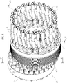
- Figure 1 represents an example of a conveying device according to the present invention, according to an axonometric view
- the conveyor device described here is intended for applications in the field of the production of smoking articles, in particular, for transporting smoking articles or parts of smoking articles.
- the device described here indicated as a whole with the reference number 10, comprises:
- the transport members 6 are mounted on the rotor 4 in a series, circular arrangement around the rotation axis 12.
- Each transport member 6 has a seat 6A for housing a smoking article or a part of a smoking article.
- the transport members 6 rotate around the rotation axis 12, due to the rotation of the rotor 4 around this axis, maintaining the same orientation regardless of the angular position assumed around the rotation axis 12.
- the transport members 6 are mounted on the rotor 4 so as to be rotatable, each around a respective rotation axis Ii parallel to the rotation axis 12 of the rotor 4.
- the transport members 6 are directly fixed to the ends 31 of respective shafts 30 mounted in the rotor 4 in a rotatable manner around the rotation axes Ii.
- Opposite ends 32 of the shafts 30 project from the rotor 4 in the opposite direction to the transport members 6, and engage the connection members 8.
- the connecting members 8 are also arranged in a circular series, around the rotation axes 12 and 11, in positions corresponding to the transport members 6.
- each connecting member 8 comprises a first end portion 81, substantially cylindrical, which is engaged by the end 32 of the shaft 30, and a second end portion 82, also substantially cylindrical, which is attached to the rotor 2.
- the connecting member 8 also comprises a connecting portion 83, which connects the two end portions 81, 82 to each other.
- the portion 81 comprises an inner cavity 81A, which is rotatably coupled with the end 32 of the shaft 30.
- the portion 82 also comprises a cavity 82A, which is rotatably engaged by a fixing pin 11 carried by the rotor 2.
- the configuration illustrated above reproduces a mechanism with operation of the Schmidt joint type, or rather, wherein the connecting members 8 perform both the function of transmitting the rotation of the rotor 2 to the rotor 4, and the function of making the shafts 30 - and therefore the transport members 6 - rotate around the rotation axes Ii so that the orientation of the transport members 6 with respect to the rotation axes I1, I2 remains constant.
- the connecting members 8 each comprise a weakened portion 84 such as to cause a privileged deformation of the connecting member 8, which induces a displacement of the end portion 81 with respect to the end portion 82 along a direction parallel to the reference axis R.
- Figure 3 schematically represents the relative movement between the two portions 81, 82 of each connecting member 8, made possible by the presence of the weakened portion 84.
- the movement indicated above has a single component, which is located on a plane orthogonal to the rotation axes 11, 12 and is parallel to the reference axis R.
- the weakened portion 84 may have various configurations depending on the structure of the connecting member 8 and on the operating requirements of the specific applications.
- the weakened portion 84 is obtained on the end portion 82.
- the weakened portion 84 may instead be obtained on the end portion 81.
- the weakened portion 84 is made by means of a plurality of through-slits 84A, which join opposite sides of the outer side surface of the end portion 82 and which extend on planes parallel to each other.
- the slits 84A identify layer regions 84B in the same portion 82, which are superimposed and separated from each other by the slits 84A.
- the slits 84A have closed ends 84A' defining bridge portions 84C, which each connect two adjacent layer regions 84B.
- the bridge portions 84C are arranged alternately in opposite positions with respect to an axis K parallel to the reference axis R.
- Each layer region 84B is detachable from the adjacent layer region by the effect of a bending deformation of the respective bridge portion 84C. This removal of the layer region occurs according to a rotation movement, around an ideal axis passing through the bridge portion, according to a given direction of rotation, which is variable according to the position wherein the relative bridge portion 84C is located with respect to the reference axis K.
- the layer region 84B moves away from the adjacent layer region 84B, which lies below (with reference to the Figure), according to a counterclockwise rotation movement.
- the layer region 84B moves away from the adjacent lower layer region 84B according to a clockwise rotation movement.
- the alternation of the bridge portions 84C in positioning with respect to the axis K causes the reciprocal removal of the layer regions 84B to cause an overall displacement of the portion 81 - or at least of its seat 81A - with respect to the portion 82 along the axis K.
- each connecting member 8 of the device described here is able to find an alignment between its own end portions 81, 82 and the seats intended to receive them obtained in the two rotors 2, 4 - or rather, the shafts 30 and the pins 11 in the illustrated embodiment -, so as to compensate for any deviations from an ideal position by the aforesaid seats.
Landscapes
- Chain Conveyers (AREA)
- Attitude Control For Articles On Conveyors (AREA)
- Agricultural Chemicals And Associated Chemicals (AREA)
Abstract
Description
- The present invention relates to a device for conveying smoking articles or parts of smoking articles, comprising:
- a first rotor, rotatable about a first rotation axis;
- a second rotor, rotatable about a second rotation axis parallel to the first rotation axis, and moved away with respect to the latter along a reference axis; and
- a plurality of conveying members for receiving smoking articles or parts of smoking articles, which are mounted on the second rotor, according to a arrangement in series around the second rotation axis, and each one is rotatable about a respective rotation axis parallel to the second rotation axis of the second rotor;
- a plurality of members for rotationally connecting the first rotor to the second rotor, which are arranged in series around the first and the second rotation axis, and each have a first end that is coupled in a rotatable manner to the first rotor, and a second end that is coupled in a rotatable manner to the second rotor, and is fixed to a respective conveying member of the plurality of conveying members.
- The structure of such a device requires a very high manufacturing precision to ensure that all the connecting members are coupled, each in a correct way, to the two rotors of the device. Any deviations in manufacturing tolerances may lead to forced couplings wherein the components have internal stresses which - in the long run - lead to premature wear of the components and a greater risk of breakage.
- The present invention aims to provide an improved solution, in particular, which is capable of operating efficiently even in the presence of deviations in manufacturing tolerances.
- This object is achieved by means of a conveying device having the characteristics referred to in claim 1. The present invention also relates to an assembly method according to claim 9.
- The claims form an integral part of the disclosure provided here.
- Further characteristics and advantages of the invention will become evident from the description that follows with reference to the attached drawings, provided purely by way of non-limiting example, wherein:
Figure 1 represents an example of a conveying device according to the present invention, according to an axonometric view; -
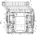
Figure 2 is a cross-sectional view of the device ofFigure 1 , according to the cross-sectional plane II-II ofFigure 1 ; -
Figure 3 is another cross-sectional view of the device ofFigure 1 , according to the cross-sectional plane III-III ofFigure 1 ; -
Figure 4 represents a connection member of the device ofFigure 1 , according to an axonometric view; -
Figure 5 represents a front view of the connecting member ofFigure 4 ; -
Figure 6 represents a cross-sectional view of the connecting member ofFigure 4 , according to the plane VI-VI ofFigure 5 . - In the following description, various specific details are illustrated aimed at a thorough understanding of the embodiments. The embodiments may be implemented without one or more of the specific details, or with other methods, components, materials, etc. In other cases, known structures, materials or operations are not shown or described in detail to avoid obscuring various aspects of the embodiments.
- The references used here are only for convenience and do not therefore define the field of protection or the scope of the embodiments.
- The conveyor device described here is intended for applications in the field of the production of smoking articles, in particular, for transporting smoking articles or parts of smoking articles.
- With reference to the Figures, the device described here, indicated as a whole with the
reference number 10, comprises: - a
first rotor 2, rotatable about a first rotation axis I1; - a
second rotor 4, rotatable about a second rotation axis 12, parallel to therotation axis 11 and moved away with respect to the latter along a reference axis R; - a plurality of
transport members 6 for receiving the smoking articles or the parts of smoking articles, which are mounted on thesecond rotor 4; and - a plurality of
members 8 for connecting therotor 2 to therotor 4 in rotation. - The
transport members 6 are mounted on therotor 4 in a series, circular arrangement around the rotation axis 12. - Each
transport member 6 has aseat 6A for housing a smoking article or a part of a smoking article. - As will be seen in detail below, during operation, the
transport members 6 rotate around the rotation axis 12, due to the rotation of therotor 4 around this axis, maintaining the same orientation regardless of the angular position assumed around the rotation axis 12. - The
transport members 6 are mounted on therotor 4 so as to be rotatable, each around a respective rotation axis Ii parallel to the rotation axis 12 of therotor 4. - In particular, in one or more preferred embodiments, such as the one illustrated, the
transport members 6 are directly fixed to theends 31 ofrespective shafts 30 mounted in therotor 4 in a rotatable manner around the rotation axes Ii. -
Opposite ends 32 of theshafts 30 project from therotor 4 in the opposite direction to thetransport members 6, and engage theconnection members 8. - The connecting
members 8 are also arranged in a circular series, around therotation axes 12 and 11, in positions corresponding to thetransport members 6. - With reference to
Figures 4, 5 and 6 , each connectingmember 8 comprises afirst end portion 81, substantially cylindrical, which is engaged by theend 32 of theshaft 30, and asecond end portion 82, also substantially cylindrical, which is attached to therotor 2. - The connecting
member 8 also comprises a connecting portion 83, which connects the twoend portions portion 81 comprises aninner cavity 81A, which is rotatably coupled with theend 32 of theshaft 30. On the other hand, theportion 82 also comprises acavity 82A, which is rotatably engaged by afixing pin 11 carried by therotor 2. - In view of the above, the person skilled in the art will understand that the configuration illustrated above reproduces a mechanism with operation of the Schmidt joint type, or rather, wherein the connecting
members 8 perform both the function of transmitting the rotation of therotor 2 to therotor 4, and the function of making the shafts 30 - and therefore the transport members 6 - rotate around the rotation axes Ii so that the orientation of thetransport members 6 with respect to the rotation axes I1, I2 remains constant. - According to an important characteristic of the solution described here, the connecting
members 8 each comprise a weakenedportion 84 such as to cause a privileged deformation of the connectingmember 8, which induces a displacement of theend portion 81 with respect to theend portion 82 along a direction parallel to the reference axis R. -
Figure 3 schematically represents the relative movement between the twoportions member 8, made possible by the presence of the weakenedportion 84. - Preferably, the movement indicated above has a single component, which is located on a plane orthogonal to the
rotation axes 11, 12 and is parallel to the reference axis R. - The weakened
portion 84 may have various configurations depending on the structure of the connectingmember 8 and on the operating requirements of the specific applications. - With reference to the embodiment illustrated in the figures, the weakened
portion 84 is obtained on theend portion 82. Alternatively, the weakenedportion 84 may instead be obtained on theend portion 81. - In one or more preferred embodiments, such as the one illustrated, the weakened
portion 84 is made by means of a plurality of through-slits 84A, which join opposite sides of the outer side surface of theend portion 82 and which extend on planes parallel to each other. - The
slits 84A identifylayer regions 84B in thesame portion 82, which are superimposed and separated from each other by theslits 84A. - The
slits 84A have closedends 84A' definingbridge portions 84C, which each connect twoadjacent layer regions 84B. - The
bridge portions 84C are arranged alternately in opposite positions with respect to an axis K parallel to the reference axis R. - Each
layer region 84B is detachable from the adjacent layer region by the effect of a bending deformation of therespective bridge portion 84C. This removal of the layer region occurs according to a rotation movement, around an ideal axis passing through the bridge portion, according to a given direction of rotation, which is variable according to the position wherein therelative bridge portion 84C is located with respect to the reference axis K. - Specifically, with reference to
Figure 6 , where therelative bridge portion 84C is to the left of the axis K, thelayer region 84B moves away from theadjacent layer region 84B, which lies below (with reference to the Figure), according to a counterclockwise rotation movement. On the contrary, where therelative bridge portion 84C is positioned to the right of the axis K, thelayer region 84B moves away from the adjacentlower layer region 84B according to a clockwise rotation movement. - The alternation of the
bridge portions 84C in positioning with respect to the axis K causes the reciprocal removal of thelayer regions 84B to cause an overall displacement of the portion 81 - or at least of itsseat 81A - with respect to theportion 82 along the axis K. - Thanks to the movement indicated, each connecting
member 8 of the device described here is able to find an alignment between itsown end portions rotors 2, 4 - or rather, theshafts 30 and thepins 11 in the illustrated embodiment -, so as to compensate for any deviations from an ideal position by the aforesaid seats. - This is achieved through, only, a deformation of the weakened
portion 84, in a controlled manner as described above, so that in the connectingmember 8 no deteriorating internal stresses are generated for the component and the means with which it cooperates. - This solution, therefore, ensures operating efficiency regardless of the actual manufacturing precision of the device components, and also facilitates the assembly operation of the device itself.
- Of course, without prejudice to the principle of the invention, the details of construction and the embodiments may vary, even significantly, with respect to those illustrated here, purely by way of non-limiting example, without departing from the scope of the invention as defined by the attached claims.
Claims (9)
- A device for conveying smoking articles or parts of smoking articles, comprising:- a first rotor (2), rotatable about a first rotation axis (11);- a second rotor (4), rotatable about a second rotation axis (12) parallel to the first rotation axis (11) and moved away with respect to the latter along a reference axis (R); and- a plurality of conveying members (6) for receiving smoking articles or parts of smoking articles, which are mounted on the second rotor (4), according to a arrangement in series around the second rotation axis (12), and each one is rotatable about a respective rotation axis (Ii) parallel to the second rotation axis (12) of the second rotor (4);- a plurality of members (8) for rotationally connecting the first rotor (2) to the second rotor (4), which are arranged in series around the first and the second rotation axis (11, 12), and each have a first end (82) that is coupled in a rotatable manner to the first rotor (2), and a second end (81) that is coupled in a rotatable manner to the second rotor (4), and is fixed to a respective conveying member (6) of the plurality of conveying members;said device being characterized in that:- each connecting member (8) comprises a weakened portion (84) such that it causes a privileged deformation of the connecting member (8) inducing a movement of the first end (81) with respect to the second end (82), along a direction parallel to the reference axis (R).
- A device according to claim 1, wherein the weakened portion (84) is made by means of removing material, preferably wire electro-erosion.
- A device according to claims 1 or 2, wherein the weakened portion (84) has a plurality of localised regions (84C) with increased flexure deformability with respect to the surrounding regions, which, when subjected to flexure deformation, cause an overall movement of the first end (82) with respect to the second end (81), along a direction parallel to the reference axis (R).
- A device according to any one of the preceding claims, wherein each connecting member (8) comprises a first portion that is substantially cylindrical (82) defining the first end of the connecting member, a second portion that is substantially cylindrical (81) defining the second end of the connecting member, which is parallel and displaced with respect to the first cylindrical portion (81), and a third portion (83) connecting the first portion (82) to the second portion (81), and wherein the weakened portion (84) is obtained on the first or second portion (81, 82).
- A device according to claim 4, wherein on the first or second cylindrical portion (81, 82) a plurality of through-slits (84A) are made, which join together opposite sides of the outer side surface of the cylindrical portion (81), and extend on planes that are parallel to one another, said slits defining layer regions (84B) in the cylindrical portion (81), which are superimposed to one another and separated from one another by the plurality of slits (84A).
- A device according to claim 5, wherein the layer regions (84B) are each connected to an adjacent layer region via respective bridge portions (84C), which are made at closed ends (84') of the slits (84A), each layer region (84B) being movable away from the adjacent layer region as a result of flexure deformation of the respective bridge portion (84C).
- A device according to claim 6, wherein the bridge portions (84C) are alternately arranged in opposite positions with respect to an axis (K) parallel to the reference axis (R), so that each layer region can be moved away from an adjacent layer region according to a rotation movement in a first rotation direction, and another layer region successive to the adjacent layer region can be moved away from the adjacent layer region according to a rotation movement in a second direction opposite to the first direction.
- A device according to any one of the preceding claims, wherein the second end (81) of the connecting member (8) is rotatable about the same rotation axis (Ii) of the respective conveying member (6).
- A method for assembling a conveyor device according to any one of the preceding claims, comprising the steps of:- providing the first rotor (2), which can rotate about the first rotation axis (I1);- providing the second rotor (4) which can rotate about the second rotation axis (12); and- mounting the plurality of conveying members (6) on the second rotor (4), according to an arrangement in series about the second rotation axis (12), and so that each conveying member (6) can rotate about a respective rotation axis (Ii) parallel to the second rotation axis (12) of the second rotor;- mounting the plurality of connecting members (8) on the first rotor and on the second rotor (2, 4) for rotationally connecting the first rotor (2) to the second rotor (4),wherein mounting each connecting member (8) comprises coupling the first end (82) of the connecting member (8) in a rotatable manner to the first rotor (2), and coupling the second end (81) of the connecting member (8) in a rotatable manner to the second rotor (4), and it is fixed to a respective conveying member (6) of the plurality of conveying members;andwherein coupling the first or the second end of the connecting member includes moving the first or the second end (82, 81) with respect to the second or first end (81, 82) of the connecting member, along a direction parallel to the reference axis (R), exclusively deforming the weakened portion (84) of the connecting member, for aligning the first or second end (82, 81) of the connecting member (8) to a respective seat made on the first or second rotor (2, 4), which is configured to receive the first or second end (82, 81) of the connecting member (8).
Applications Claiming Priority (1)
| Application Number | Priority Date | Filing Date | Title |
|---|---|---|---|
| IT102021000016979A IT202100016979A1 (en) | 2021-06-29 | 2021-06-29 | Device for conveying smoking articles or parts of smoking articles |
Publications (2)
| Publication Number | Publication Date |
|---|---|
| EP4111874A1 true EP4111874A1 (en) | 2023-01-04 |
| EP4111874B1 EP4111874B1 (en) | 2023-12-27 |
Family
ID=77802103
Family Applications (1)
| Application Number | Title | Priority Date | Filing Date |
|---|---|---|---|
| EP22180450.3A Active EP4111874B1 (en) | 2021-06-29 | 2022-06-22 | A device for conveying smoking articles or parts of smoking articles |
Country Status (3)
| Country | Link |
|---|---|
| EP (1) | EP4111874B1 (en) |
| IT (1) | IT202100016979A1 (en) |
| PL (1) | PL4111874T3 (en) |
Citations (3)
| Publication number | Priority date | Publication date | Assignee | Title |
|---|---|---|---|---|
| US4244250A (en) * | 1977-10-19 | 1981-01-13 | Hauni-Werke Korber & Co. Kg | Apparatus for transporting tools in machines for the processing of rod-shaped articles |
| US4408621A (en) * | 1980-06-19 | 1983-10-11 | Hauni-Werke Korber & Co. Kg. | Apparatus for transferring cigarettes or the like |
| US5322157A (en) * | 1991-06-27 | 1994-06-21 | Decoufle S.A.R.L. | Apparatus for transferring and changing the direction of transport of rod-shaped articles |
-
2021
- 2021-06-29 IT IT102021000016979A patent/IT202100016979A1/en unknown
-
2022
- 2022-06-22 PL PL22180450.3T patent/PL4111874T3/en unknown
- 2022-06-22 EP EP22180450.3A patent/EP4111874B1/en active Active
Patent Citations (3)
| Publication number | Priority date | Publication date | Assignee | Title |
|---|---|---|---|---|
| US4244250A (en) * | 1977-10-19 | 1981-01-13 | Hauni-Werke Korber & Co. Kg | Apparatus for transporting tools in machines for the processing of rod-shaped articles |
| US4408621A (en) * | 1980-06-19 | 1983-10-11 | Hauni-Werke Korber & Co. Kg. | Apparatus for transferring cigarettes or the like |
| US5322157A (en) * | 1991-06-27 | 1994-06-21 | Decoufle S.A.R.L. | Apparatus for transferring and changing the direction of transport of rod-shaped articles |
Also Published As
| Publication number | Publication date |
|---|---|
| IT202100016979A1 (en) | 2022-12-29 |
| EP4111874B1 (en) | 2023-12-27 |
| PL4111874T3 (en) | 2024-04-29 |
Similar Documents
| Publication | Publication Date | Title |
|---|---|---|
| EP3692626B1 (en) | Piezoelectric drive unit | |
| JP5085913B2 (en) | Composite filter manufacturing machine | |
| EP3589853B1 (en) | Flexural pivot | |
| US7077619B2 (en) | Continuous motion robotic manipulator | |
| EP4111874B1 (en) | A device for conveying smoking articles or parts of smoking articles | |
| JP6761131B2 (en) | Deflection Pivot, Deflection Pivot System and Manufacturing Method | |
| EP2805899B1 (en) | Transport chain & transport chain system | |
| EP1878544A1 (en) | Parallel positioning mechanism with articulated upper arm | |
| CA2795238C (en) | Rotor system anti-rotation wear protector | |
| US20160123196A1 (en) | Adjustment drive | |
| CN103402716B (en) | Machine tool system | |
| US11130224B2 (en) | Parallel link robot | |
| KR101888898B1 (en) | Wiper device, method for manufacturing wiper device, and device for manufacturing wiper device | |
| EP3838509B1 (en) | Electric gripping device | |
| EP2952766B1 (en) | A double cardan shaft with a centering piece integrated with the spider connection bearing and method of making the same | |
| JP2004269259A (en) | Conveying chain | |
| US20200238352A1 (en) | Power transmission device and rolling mill | |
| WO2017018046A1 (en) | Transport chain | |
| CN115916474B (en) | Robotic device | |
| CN103286382A (en) | Machine tool splitting device | |
| CN108292871A (en) | Electric rotating machine | |
| CN118946436A (en) | Parallel Link Robot | |
| US11092213B2 (en) | Gear mechanism, gear adjustment method and robot | |
| US11662011B2 (en) | Pump assembly and method for producing a pump assembly | |
| CN212643352U (en) | Shaft coupling |
Legal Events
| Date | Code | Title | Description |
|---|---|---|---|
| PUAI | Public reference made under article 153(3) epc to a published international application that has entered the european phase |
Free format text: ORIGINAL CODE: 0009012 |
|
| STAA | Information on the status of an ep patent application or granted ep patent |
Free format text: STATUS: THE APPLICATION HAS BEEN PUBLISHED |
|
| AK | Designated contracting states |
Kind code of ref document: A1 Designated state(s): AL AT BE BG CH CY CZ DE DK EE ES FI FR GB GR HR HU IE IS IT LI LT LU LV MC MK MT NL NO PL PT RO RS SE SI SK SM TR |
|
| STAA | Information on the status of an ep patent application or granted ep patent |
Free format text: STATUS: REQUEST FOR EXAMINATION WAS MADE |
|
| 17P | Request for examination filed |
Effective date: 20230309 |
|
| RBV | Designated contracting states (corrected) |
Designated state(s): AL AT BE BG CH CY CZ DE DK EE ES FI FR GB GR HR HU IE IS IT LI LT LU LV MC MK MT NL NO PL PT RO RS SE SI SK SM TR |
|
| P01 | Opt-out of the competence of the unified patent court (upc) registered |
Effective date: 20230524 |
|
| GRAP | Despatch of communication of intention to grant a patent |
Free format text: ORIGINAL CODE: EPIDOSNIGR1 |
|
| STAA | Information on the status of an ep patent application or granted ep patent |
Free format text: STATUS: GRANT OF PATENT IS INTENDED |
|
| INTG | Intention to grant announced |
Effective date: 20230809 |
|
| GRAS | Grant fee paid |
Free format text: ORIGINAL CODE: EPIDOSNIGR3 |
|
| GRAA | (expected) grant |
Free format text: ORIGINAL CODE: 0009210 |
|
| STAA | Information on the status of an ep patent application or granted ep patent |
Free format text: STATUS: THE PATENT HAS BEEN GRANTED |
|
| AK | Designated contracting states |
Kind code of ref document: B1 Designated state(s): AL AT BE BG CH CY CZ DE DK EE ES FI FR GB GR HR HU IE IS IT LI LT LU LV MC MK MT NL NO PL PT RO RS SE SI SK SM TR |
|
| REG | Reference to a national code |
Ref country code: GB Ref legal event code: FG4D |
|
| REG | Reference to a national code |
Ref country code: CH Ref legal event code: EP |
|
| REG | Reference to a national code |
Ref country code: DE Ref legal event code: R096 Ref document number: 602022001469 Country of ref document: DE |
|
| REG | Reference to a national code |
Ref country code: IE Ref legal event code: FG4D |
|
| REG | Reference to a national code |
Ref country code: NL Ref legal event code: FP |
|
| PG25 | Lapsed in a contracting state [announced via postgrant information from national office to epo] |
Ref country code: GR Free format text: LAPSE BECAUSE OF FAILURE TO SUBMIT A TRANSLATION OF THE DESCRIPTION OR TO PAY THE FEE WITHIN THE PRESCRIBED TIME-LIMIT Effective date: 20240328 |
|
| REG | Reference to a national code |
Ref country code: LT Ref legal event code: MG9D |
|
| PG25 | Lapsed in a contracting state [announced via postgrant information from national office to epo] |
Ref country code: LT Free format text: LAPSE BECAUSE OF FAILURE TO SUBMIT A TRANSLATION OF THE DESCRIPTION OR TO PAY THE FEE WITHIN THE PRESCRIBED TIME-LIMIT Effective date: 20231227 |
|
| PG25 | Lapsed in a contracting state [announced via postgrant information from national office to epo] |
Ref country code: ES Free format text: LAPSE BECAUSE OF FAILURE TO SUBMIT A TRANSLATION OF THE DESCRIPTION OR TO PAY THE FEE WITHIN THE PRESCRIBED TIME-LIMIT Effective date: 20231227 |
|
| PG25 | Lapsed in a contracting state [announced via postgrant information from national office to epo] |
Ref country code: LT Free format text: LAPSE BECAUSE OF FAILURE TO SUBMIT A TRANSLATION OF THE DESCRIPTION OR TO PAY THE FEE WITHIN THE PRESCRIBED TIME-LIMIT Effective date: 20231227 Ref country code: GR Free format text: LAPSE BECAUSE OF FAILURE TO SUBMIT A TRANSLATION OF THE DESCRIPTION OR TO PAY THE FEE WITHIN THE PRESCRIBED TIME-LIMIT Effective date: 20240328 Ref country code: FI Free format text: LAPSE BECAUSE OF FAILURE TO SUBMIT A TRANSLATION OF THE DESCRIPTION OR TO PAY THE FEE WITHIN THE PRESCRIBED TIME-LIMIT Effective date: 20231227 Ref country code: ES Free format text: LAPSE BECAUSE OF FAILURE TO SUBMIT A TRANSLATION OF THE DESCRIPTION OR TO PAY THE FEE WITHIN THE PRESCRIBED TIME-LIMIT Effective date: 20231227 Ref country code: BG Free format text: LAPSE BECAUSE OF FAILURE TO SUBMIT A TRANSLATION OF THE DESCRIPTION OR TO PAY THE FEE WITHIN THE PRESCRIBED TIME-LIMIT Effective date: 20240327 |
|
| REG | Reference to a national code |
Ref country code: AT Ref legal event code: MK05 Ref document number: 1643664 Country of ref document: AT Kind code of ref document: T Effective date: 20231227 |
|
| PG25 | Lapsed in a contracting state [announced via postgrant information from national office to epo] |
Ref country code: SE Free format text: LAPSE BECAUSE OF FAILURE TO SUBMIT A TRANSLATION OF THE DESCRIPTION OR TO PAY THE FEE WITHIN THE PRESCRIBED TIME-LIMIT Effective date: 20231227 Ref country code: RS Free format text: LAPSE BECAUSE OF FAILURE TO SUBMIT A TRANSLATION OF THE DESCRIPTION OR TO PAY THE FEE WITHIN THE PRESCRIBED TIME-LIMIT Effective date: 20231227 Ref country code: NO Free format text: LAPSE BECAUSE OF FAILURE TO SUBMIT A TRANSLATION OF THE DESCRIPTION OR TO PAY THE FEE WITHIN THE PRESCRIBED TIME-LIMIT Effective date: 20240327 Ref country code: LV Free format text: LAPSE BECAUSE OF FAILURE TO SUBMIT A TRANSLATION OF THE DESCRIPTION OR TO PAY THE FEE WITHIN THE PRESCRIBED TIME-LIMIT Effective date: 20231227 Ref country code: HR Free format text: LAPSE BECAUSE OF FAILURE TO SUBMIT A TRANSLATION OF THE DESCRIPTION OR TO PAY THE FEE WITHIN THE PRESCRIBED TIME-LIMIT Effective date: 20231227 |
|
| PG25 | Lapsed in a contracting state [announced via postgrant information from national office to epo] |
Ref country code: IS Free format text: LAPSE BECAUSE OF FAILURE TO SUBMIT A TRANSLATION OF THE DESCRIPTION OR TO PAY THE FEE WITHIN THE PRESCRIBED TIME-LIMIT Effective date: 20240427 |
|
| PG25 | Lapsed in a contracting state [announced via postgrant information from national office to epo] |
Ref country code: CZ Free format text: LAPSE BECAUSE OF FAILURE TO SUBMIT A TRANSLATION OF THE DESCRIPTION OR TO PAY THE FEE WITHIN THE PRESCRIBED TIME-LIMIT Effective date: 20231227 Ref country code: AT Free format text: LAPSE BECAUSE OF FAILURE TO SUBMIT A TRANSLATION OF THE DESCRIPTION OR TO PAY THE FEE WITHIN THE PRESCRIBED TIME-LIMIT Effective date: 20231227 |
|
| PG25 | Lapsed in a contracting state [announced via postgrant information from national office to epo] |
Ref country code: SK Free format text: LAPSE BECAUSE OF FAILURE TO SUBMIT A TRANSLATION OF THE DESCRIPTION OR TO PAY THE FEE WITHIN THE PRESCRIBED TIME-LIMIT Effective date: 20231227 |
|
| PG25 | Lapsed in a contracting state [announced via postgrant information from national office to epo] |
Ref country code: SM Free format text: LAPSE BECAUSE OF FAILURE TO SUBMIT A TRANSLATION OF THE DESCRIPTION OR TO PAY THE FEE WITHIN THE PRESCRIBED TIME-LIMIT Effective date: 20231227 Ref country code: SK Free format text: LAPSE BECAUSE OF FAILURE TO SUBMIT A TRANSLATION OF THE DESCRIPTION OR TO PAY THE FEE WITHIN THE PRESCRIBED TIME-LIMIT Effective date: 20231227 Ref country code: RO Free format text: LAPSE BECAUSE OF FAILURE TO SUBMIT A TRANSLATION OF THE DESCRIPTION OR TO PAY THE FEE WITHIN THE PRESCRIBED TIME-LIMIT Effective date: 20231227 Ref country code: IT Free format text: LAPSE BECAUSE OF FAILURE TO SUBMIT A TRANSLATION OF THE DESCRIPTION OR TO PAY THE FEE WITHIN THE PRESCRIBED TIME-LIMIT Effective date: 20231227 Ref country code: IS Free format text: LAPSE BECAUSE OF FAILURE TO SUBMIT A TRANSLATION OF THE DESCRIPTION OR TO PAY THE FEE WITHIN THE PRESCRIBED TIME-LIMIT Effective date: 20240427 Ref country code: EE Free format text: LAPSE BECAUSE OF FAILURE TO SUBMIT A TRANSLATION OF THE DESCRIPTION OR TO PAY THE FEE WITHIN THE PRESCRIBED TIME-LIMIT Effective date: 20231227 Ref country code: CZ Free format text: LAPSE BECAUSE OF FAILURE TO SUBMIT A TRANSLATION OF THE DESCRIPTION OR TO PAY THE FEE WITHIN THE PRESCRIBED TIME-LIMIT Effective date: 20231227 Ref country code: AT Free format text: LAPSE BECAUSE OF FAILURE TO SUBMIT A TRANSLATION OF THE DESCRIPTION OR TO PAY THE FEE WITHIN THE PRESCRIBED TIME-LIMIT Effective date: 20231227 |
|
| PG25 | Lapsed in a contracting state [announced via postgrant information from national office to epo] |
Ref country code: PT Free format text: LAPSE BECAUSE OF FAILURE TO SUBMIT A TRANSLATION OF THE DESCRIPTION OR TO PAY THE FEE WITHIN THE PRESCRIBED TIME-LIMIT Effective date: 20240429 |
|
| PG25 | Lapsed in a contracting state [announced via postgrant information from national office to epo] |
Ref country code: PT Free format text: LAPSE BECAUSE OF FAILURE TO SUBMIT A TRANSLATION OF THE DESCRIPTION OR TO PAY THE FEE WITHIN THE PRESCRIBED TIME-LIMIT Effective date: 20240429 |
|
| REG | Reference to a national code |
Ref country code: DE Ref legal event code: R097 Ref document number: 602022001469 Country of ref document: DE |
|
| PG25 | Lapsed in a contracting state [announced via postgrant information from national office to epo] |
Ref country code: DK Free format text: LAPSE BECAUSE OF FAILURE TO SUBMIT A TRANSLATION OF THE DESCRIPTION OR TO PAY THE FEE WITHIN THE PRESCRIBED TIME-LIMIT Effective date: 20231227 |
|
| PG25 | Lapsed in a contracting state [announced via postgrant information from national office to epo] |
Ref country code: DK Free format text: LAPSE BECAUSE OF FAILURE TO SUBMIT A TRANSLATION OF THE DESCRIPTION OR TO PAY THE FEE WITHIN THE PRESCRIBED TIME-LIMIT Effective date: 20231227 |
|
| PLBE | No opposition filed within time limit |
Free format text: ORIGINAL CODE: 0009261 |
|
| STAA | Information on the status of an ep patent application or granted ep patent |
Free format text: STATUS: NO OPPOSITION FILED WITHIN TIME LIMIT |
|
| 26N | No opposition filed |
Effective date: 20240930 |
|
| PG25 | Lapsed in a contracting state [announced via postgrant information from national office to epo] |
Ref country code: MC Free format text: LAPSE BECAUSE OF FAILURE TO SUBMIT A TRANSLATION OF THE DESCRIPTION OR TO PAY THE FEE WITHIN THE PRESCRIBED TIME-LIMIT Effective date: 20231227 |
|
| PG25 | Lapsed in a contracting state [announced via postgrant information from national office to epo] |
Ref country code: LU Free format text: LAPSE BECAUSE OF NON-PAYMENT OF DUE FEES Effective date: 20240622 |
|
| PG25 | Lapsed in a contracting state [announced via postgrant information from national office to epo] |
Ref country code: IE Free format text: LAPSE BECAUSE OF NON-PAYMENT OF DUE FEES Effective date: 20240622 |
|
| PG25 | Lapsed in a contracting state [announced via postgrant information from national office to epo] |
Ref country code: BE Free format text: LAPSE BECAUSE OF NON-PAYMENT OF DUE FEES Effective date: 20240630 Ref country code: SI Free format text: LAPSE BECAUSE OF FAILURE TO SUBMIT A TRANSLATION OF THE DESCRIPTION OR TO PAY THE FEE WITHIN THE PRESCRIBED TIME-LIMIT Effective date: 20231227 |
|
| PG25 | Lapsed in a contracting state [announced via postgrant information from national office to epo] |
Ref country code: FR Free format text: LAPSE BECAUSE OF NON-PAYMENT OF DUE FEES Effective date: 20240630 |
|
| REG | Reference to a national code |
Ref country code: BE Ref legal event code: MM Effective date: 20240630 |
|
| PG25 | Lapsed in a contracting state [announced via postgrant information from national office to epo] |
Ref country code: CY Free format text: LAPSE BECAUSE OF FAILURE TO SUBMIT A TRANSLATION OF THE DESCRIPTION OR TO PAY THE FEE WITHIN THE PRESCRIBED TIME-LIMIT; INVALID AB INITIO Effective date: 20220622 |
|
| REG | Reference to a national code |
Ref country code: CH Ref legal event code: H13 Free format text: ST27 STATUS EVENT CODE: U-0-0-H10-H13 (AS PROVIDED BY THE NATIONAL OFFICE) Effective date: 20260127 |
|
| PG25 | Lapsed in a contracting state [announced via postgrant information from national office to epo] |
Ref country code: HU Free format text: LAPSE BECAUSE OF FAILURE TO SUBMIT A TRANSLATION OF THE DESCRIPTION OR TO PAY THE FEE WITHIN THE PRESCRIBED TIME-LIMIT; INVALID AB INITIO Effective date: 20220622 |
|
| PG25 | Lapsed in a contracting state [announced via postgrant information from national office to epo] |
Ref country code: CH Free format text: LAPSE BECAUSE OF NON-PAYMENT OF DUE FEES Effective date: 20250630 |
|
| PG25 | Lapsed in a contracting state [announced via postgrant information from national office to epo] |
Ref country code: TR Free format text: LAPSE BECAUSE OF FAILURE TO SUBMIT A TRANSLATION OF THE DESCRIPTION OR TO PAY THE FEE WITHIN THE PRESCRIBED TIME-LIMIT Effective date: 20231227 |
|
| PG25 | Lapsed in a contracting state [announced via postgrant information from national office to epo] |
Ref country code: CH Free format text: THE PATENT HAS BEEN ANNULLED BY A DECISION OF A NATIONAL AUTHORITY Effective date: 20250630 |
|
| PGFP | Annual fee paid to national office [announced via postgrant information from national office to epo] |
Ref country code: PL Payment date: 20260608 Year of fee payment: 5 |
|
| PGFP | Annual fee paid to national office [announced via postgrant information from national office to epo] |
Ref country code: DE Payment date: 20260629 Year of fee payment: 5 |
|
| PGFP | Annual fee paid to national office [announced via postgrant information from national office to epo] |
Ref country code: NL Payment date: 20260627 Year of fee payment: 5 |