EP4111516B1 - Flow-through protective system of hydrogen fuel receiver and method of protection of hydrogen fuel receiver - Google Patents
Flow-through protective system of hydrogen fuel receiver and method of protection of hydrogen fuel receiver Download PDFInfo
- Publication number
- EP4111516B1 EP4111516B1 EP21719707.8A EP21719707A EP4111516B1 EP 4111516 B1 EP4111516 B1 EP 4111516B1 EP 21719707 A EP21719707 A EP 21719707A EP 4111516 B1 EP4111516 B1 EP 4111516B1
- Authority
- EP
- European Patent Office
- Prior art keywords
- valve
- hydrogen
- measurement
- sensor
- unit
- Prior art date
- Legal status (The legal status is an assumption and is not a legal conclusion. Google has not performed a legal analysis and makes no representation as to the accuracy of the status listed.)
- Active
Links
Images



Classifications
-
- H—ELECTRICITY
- H01—ELECTRIC ELEMENTS
- H01M—PROCESSES OR MEANS, e.g. BATTERIES, FOR THE DIRECT CONVERSION OF CHEMICAL ENERGY INTO ELECTRICAL ENERGY
- H01M8/00—Fuel cells; Manufacture thereof
- H01M8/04—Auxiliary arrangements, e.g. for control of pressure or for circulation of fluids
- H01M8/04082—Arrangements for control of reactant parameters, e.g. pressure or concentration
- H01M8/04201—Reactant storage and supply, e.g. means for feeding, pipes
-
- G—PHYSICS
- G01—MEASURING; TESTING
- G01J—MEASUREMENT OF INTENSITY, VELOCITY, SPECTRAL CONTENT, POLARISATION, PHASE OR PULSE CHARACTERISTICS OF INFRARED, VISIBLE OR ULTRAVIOLET LIGHT; COLORIMETRY; RADIATION PYROMETRY
- G01J3/00—Spectrometry; Spectrophotometry; Monochromators; Measuring colours
- G01J3/02—Details
- G01J3/0205—Optical elements not provided otherwise, e.g. optical manifolds, diffusers, windows
- G01J3/021—Optical elements not provided otherwise, e.g. optical manifolds, diffusers, windows using plane or convex mirrors, parallel phase plates, or particular reflectors
-
- G—PHYSICS
- G01—MEASURING; TESTING
- G01J—MEASUREMENT OF INTENSITY, VELOCITY, SPECTRAL CONTENT, POLARISATION, PHASE OR PULSE CHARACTERISTICS OF INFRARED, VISIBLE OR ULTRAVIOLET LIGHT; COLORIMETRY; RADIATION PYROMETRY
- G01J3/00—Spectrometry; Spectrophotometry; Monochromators; Measuring colours
- G01J3/02—Details
- G01J3/0205—Optical elements not provided otherwise, e.g. optical manifolds, diffusers, windows
- G01J3/0216—Optical elements not provided otherwise, e.g. optical manifolds, diffusers, windows using light concentrators or collectors or condensers
-
- G—PHYSICS
- G01—MEASURING; TESTING
- G01J—MEASUREMENT OF INTENSITY, VELOCITY, SPECTRAL CONTENT, POLARISATION, PHASE OR PULSE CHARACTERISTICS OF INFRARED, VISIBLE OR ULTRAVIOLET LIGHT; COLORIMETRY; RADIATION PYROMETRY
- G01J3/00—Spectrometry; Spectrophotometry; Monochromators; Measuring colours
- G01J3/02—Details
- G01J3/0291—Housings; Spectrometer accessories; Spatial arrangement of elements, e.g. folded path arrangements
-
- G—PHYSICS
- G01—MEASURING; TESTING
- G01J—MEASUREMENT OF INTENSITY, VELOCITY, SPECTRAL CONTENT, POLARISATION, PHASE OR PULSE CHARACTERISTICS OF INFRARED, VISIBLE OR ULTRAVIOLET LIGHT; COLORIMETRY; RADIATION PYROMETRY
- G01J3/00—Spectrometry; Spectrophotometry; Monochromators; Measuring colours
- G01J3/02—Details
- G01J3/10—Arrangements of light sources specially adapted for spectrometry or colorimetry
-
- G—PHYSICS
- G01—MEASURING; TESTING
- G01J—MEASUREMENT OF INTENSITY, VELOCITY, SPECTRAL CONTENT, POLARISATION, PHASE OR PULSE CHARACTERISTICS OF INFRARED, VISIBLE OR ULTRAVIOLET LIGHT; COLORIMETRY; RADIATION PYROMETRY
- G01J3/00—Spectrometry; Spectrophotometry; Monochromators; Measuring colours
- G01J3/28—Investigating the spectrum
- G01J3/42—Absorption spectrometry; Double beam spectrometry; Flicker spectrometry; Reflection spectrometry
-
- G—PHYSICS
- G01—MEASURING; TESTING
- G01J—MEASUREMENT OF INTENSITY, VELOCITY, SPECTRAL CONTENT, POLARISATION, PHASE OR PULSE CHARACTERISTICS OF INFRARED, VISIBLE OR ULTRAVIOLET LIGHT; COLORIMETRY; RADIATION PYROMETRY
- G01J3/00—Spectrometry; Spectrophotometry; Monochromators; Measuring colours
- G01J3/28—Investigating the spectrum
- G01J3/42—Absorption spectrometry; Double beam spectrometry; Flicker spectrometry; Reflection spectrometry
- G01J3/433—Modulation spectrometry; Derivative spectrometry
-
- G—PHYSICS
- G01—MEASURING; TESTING
- G01N—INVESTIGATING OR ANALYSING MATERIALS BY DETERMINING THEIR CHEMICAL OR PHYSICAL PROPERTIES
- G01N21/00—Investigating or analysing materials by the use of optical means, i.e. using sub-millimetre waves, infrared, visible or ultraviolet light
- G01N21/17—Systems in which incident light is modified in accordance with the properties of the material investigated
- G01N21/25—Colour; Spectral properties, i.e. comparison of effect of material on the light at two or more different wavelengths or wavelength bands
- G01N21/31—Investigating relative effect of material at wavelengths characteristic of specific elements or molecules, e.g. atomic absorption spectrometry
-
- H—ELECTRICITY
- H01—ELECTRIC ELEMENTS
- H01M—PROCESSES OR MEANS, e.g. BATTERIES, FOR THE DIRECT CONVERSION OF CHEMICAL ENERGY INTO ELECTRICAL ENERGY
- H01M8/00—Fuel cells; Manufacture thereof
- H01M8/04—Auxiliary arrangements, e.g. for control of pressure or for circulation of fluids
- H01M8/04298—Processes for controlling fuel cells or fuel cell systems
- H01M8/04313—Processes for controlling fuel cells or fuel cell systems characterised by the detection or assessment of variables; characterised by the detection or assessment of failure or abnormal function
- H01M8/0444—Concentration; Density
- H01M8/04447—Concentration; Density of anode reactants at the inlet or inside the fuel cell
-
- H—ELECTRICITY
- H01—ELECTRIC ELEMENTS
- H01M—PROCESSES OR MEANS, e.g. BATTERIES, FOR THE DIRECT CONVERSION OF CHEMICAL ENERGY INTO ELECTRICAL ENERGY
- H01M8/00—Fuel cells; Manufacture thereof
- H01M8/04—Auxiliary arrangements, e.g. for control of pressure or for circulation of fluids
- H01M8/04298—Processes for controlling fuel cells or fuel cell systems
- H01M8/04313—Processes for controlling fuel cells or fuel cell systems characterised by the detection or assessment of variables; characterised by the detection or assessment of failure or abnormal function
- H01M8/04664—Failure or abnormal function
-
- H—ELECTRICITY
- H01—ELECTRIC ELEMENTS
- H01M—PROCESSES OR MEANS, e.g. BATTERIES, FOR THE DIRECT CONVERSION OF CHEMICAL ENERGY INTO ELECTRICAL ENERGY
- H01M8/00—Fuel cells; Manufacture thereof
- H01M8/04—Auxiliary arrangements, e.g. for control of pressure or for circulation of fluids
- H01M8/04298—Processes for controlling fuel cells or fuel cell systems
- H01M8/04694—Processes for controlling fuel cells or fuel cell systems characterised by variables to be controlled
- H01M8/04746—Pressure; Flow
- H01M8/04753—Pressure; Flow of fuel cell reactants
-
- H—ELECTRICITY
- H01—ELECTRIC ELEMENTS
- H01M—PROCESSES OR MEANS, e.g. BATTERIES, FOR THE DIRECT CONVERSION OF CHEMICAL ENERGY INTO ELECTRICAL ENERGY
- H01M8/00—Fuel cells; Manufacture thereof
- H01M8/04—Auxiliary arrangements, e.g. for control of pressure or for circulation of fluids
- H01M8/04298—Processes for controlling fuel cells or fuel cell systems
- H01M8/04694—Processes for controlling fuel cells or fuel cell systems characterised by variables to be controlled
- H01M8/04955—Shut-off or shut-down of fuel cells
-
- G—PHYSICS
- G01—MEASURING; TESTING
- G01N—INVESTIGATING OR ANALYSING MATERIALS BY DETERMINING THEIR CHEMICAL OR PHYSICAL PROPERTIES
- G01N21/00—Investigating or analysing materials by the use of optical means, i.e. using sub-millimetre waves, infrared, visible or ultraviolet light
- G01N21/17—Systems in which incident light is modified in accordance with the properties of the material investigated
- G01N21/25—Colour; Spectral properties, i.e. comparison of effect of material on the light at two or more different wavelengths or wavelength bands
- G01N21/31—Investigating relative effect of material at wavelengths characteristic of specific elements or molecules, e.g. atomic absorption spectrometry
- G01N21/35—Investigating relative effect of material at wavelengths characteristic of specific elements or molecules, e.g. atomic absorption spectrometry using infrared light
- G01N21/3581—Investigating relative effect of material at wavelengths characteristic of specific elements or molecules, e.g. atomic absorption spectrometry using infrared light using far infrared light; using Terahertz radiation
-
- Y—GENERAL TAGGING OF NEW TECHNOLOGICAL DEVELOPMENTS; GENERAL TAGGING OF CROSS-SECTIONAL TECHNOLOGIES SPANNING OVER SEVERAL SECTIONS OF THE IPC; TECHNICAL SUBJECTS COVERED BY FORMER USPC CROSS-REFERENCE ART COLLECTIONS [XRACs] AND DIGESTS
- Y02—TECHNOLOGIES OR APPLICATIONS FOR MITIGATION OR ADAPTATION AGAINST CLIMATE CHANGE
- Y02E—REDUCTION OF GREENHOUSE GAS [GHG] EMISSIONS, RELATED TO ENERGY GENERATION, TRANSMISSION OR DISTRIBUTION
- Y02E60/00—Enabling technologies; Technologies with a potential or indirect contribution to GHG emissions mitigation
- Y02E60/30—Hydrogen technology
- Y02E60/50—Fuel cells
Definitions
- the invention concerns a flow-through protective system of hydrogen fuel receiver and a method of protection of hydrogen fuel receiver.
- a division is conventional, but due to the used technics of spectrum analysis, one distinguishes subterahertz spectrometers operating in a range of about 100 GHz to 1 THz, terahertz spectrometers operating in a range of about 1 THz to 10 THz and photonic spectrometers operating in a range of far infrared, infrared, visible radiation, or even ultraviolet.
- US2019212260A1 discloses a method and device for monitoring the quality of gaseous media using spectrometer, and measurements in the chamber closed with two valves is discussed in FENG DONG ET AL: "Rapid, Online Quantification of H2S in .JP-8 Fuel Reformate Using Near-Infrared Cavity-Enhanced Laser Absorption Spectroscopy", ANALYTICAL CHEMISTRY, ACS, US, vol. 83, no. 11, June 2011, pages 4132-4136, XP055434310, ISSN: 0003-2700, DOI: 10.1021/a0200300t
- a flow-through protective system of hydrogen fuel receiver comprising a line for carrying hydrogen fuel, secured with a protective valve, wherein on the line a branching unit is provided, conveying a part of the hydrogen fuel to a sensory unit, and a control unit receiving on an input a signal from the sensory unit and having an output connected to a control input of the protective valve, according to the invention is characterized in that the sensory unit comprises a measuring chamber with a semiconductor sensor with an operating band falling within the range of 100 GHz to 1000 GHz and at least one sensor chosen from the group comprising a terahertz or photonic spectrometer.
- a first valve Between the branching unit and the sensory unit is a first valve whereas an outlet of the first valve is connected to an inlet of the measuring chamber of the sensory unit and an outlet of the measuring chamber is secured with a second controllable valve, to which a pump is connected.
- a second controllable valve to which a pump is connected.
- the system comprises an alarm signalling device connected to the control unit. Consequently, in addition to securing the receiver, it is possible to notify supervisors about the contamination.
- the sensory unit comprises a subterahertz semiconductor sensor with an operating band falling within the range of 100 GHz to 1000 GHz it is fast and comprise a spectral range allowing for detection of significant subset of contaminants which can typically occur in hydrogen.
- the sensory unit comprises a spectrometric terahertz sensor, with an operating band falling within the range of 1 THz to 3 THz. This spectral range allows for detecting significant subset of contaminants which can typically occur in hydrogen.
- the system comprises a tight measuring chamber in which there is a first subterahertz semiconductor sensor with an operating band falling within the range of 100 GHz to 1000 GHz and a second sensor - terahertz spectrometer with an operating band falling within the range of 1 THz to 3 THz.
- a first subterahertz semiconductor sensor with an operating band falling within the range of 100 GHz to 1000 GHz
- a second sensor - terahertz spectrometer with an operating band falling within the range of 1 THz to 3 THz.
- a method of protection of hydrogen fuel receiver comprising a detection of transgression of parameters and cutting off supply of hydrogen by closing a controllable valve, according to the invention is characterized in that a system according to the invention is used to carry out measurement by regulating conditions inside the chamber of the sensory unit by means of the first valve and/or the second valve and the pump and then the sensor is started and a result is recorded, and hydrogen supply in the line is cut off if molar concentration of contaminants is detected above a predefined value.
- the measurement system further allows, by measuring pressure continuously by means of the manometer, opening of the first valve and operating of the pump and/or the second valve is regulated in order to achieve a state of vacuum with dynamic flow in the measuring chamber of the sensory unit.
- Such method is more stable and ensures better control of the state of the gas and the measurement speed.
- the cut off of hydrogen is signalized by sending an alarm signal and a predefined value advantageously corresponds to the molar concentration of 1e-6.
- At least one sensor constitutes a semiconductor subterahertz spectrometer, with operating band falling within the range of 100 GHz to 1000 GHz and the measurement by means of this sensor is carried out as the last.
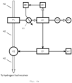
- FIG. 4a A block diagram of the device constituting an embodiment of the invention of the protective system against contaminations in hydrogen fuel was shown in Fig. 4a .
- the protective system comprising a line H2 to carry hydrogen fuel to the receiver is closable with a controllable protective valve VZ.
- a branching unit T1 On the line H2 a branching unit T1 is provided, discharging a part of hydrogen fuel to a sensory unit K1, comprising a measuring chamber with a sensor. Good results were obtained by using subterahertz semiconductor sensor with an operating band falling within the range of 100 GHz to 1000 GHz.
- the sensory unit K1 is situated between two valves, a first valve V1 and a second valve V2, so that the measurement can be done in the conditions fixed at that time.
- a manometer M1 For measuring pressure in the measuring chamber a manometer M1 is used.
- the first valve V1 a needle valve with control unit of the valve B1 connected to manometer M1 was used. Owing to that, it is possible to measure out proper pressure from the line H2 regardless of the prevailing current conditions in the line H2: pressure and flow rate. Consequently, by measuring out the gas via the first valve V1, the measurement result is made independent of the pressure changes in the line H2.
- Using a system of the electronic controllable valves and the pump P1 allows for precise pressure adjustment.
- Terahertz sensors showed higher sensitivity and the ability to distinguish wider spectrum of contaminant substances, although the measurement by means of them lasts longer.
- Those are complementary sensors which can be better for some contaminants. However, often they are less stable than subterahertz sensors based only on electronic sources and detectors, in which lasers are not used.
- the sensory unit K1 is connected to the control unit C1 generating a control signal for the protective valve VZ. Protection of hydrogen fuel receiver lies in that by means of the control unit C1, a signal closing the controllable valve VZ is generated, in the situation when by means of the sensory unit K1 unacceptable concentrations of contaminants are detected. Additionally, the protective system is optionally provided with a signaling device A1, which triggers itself closing the controllable valve VZ.
- the control unit C1 can be also used for controlling the pump P1.
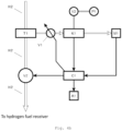
- Control unit C1 can be also used for controlling the first valve V1. Such configuration is shown in Fig. 4b . Coupling the first valve with the manometer M1 - via the control unit of the valve B1 or via the control unit C1 allows for measuring out pressure in addition to the operating of the pump P1. Using of it facilitates the proper choice of pressure and allows for pumping-out measured gas and repeating the measurement in pressure conditions significantly below atmospheric pressure.
- the system according to the invention can operate in a continuous mode or in a sequential mode.
- the system according to the invention operates in a cycle, in which in the chamber of the sensory unit K1 closed from the both sides by the first valve V1 and second valve V2, initially there is a vacuum, then the unit is filled with hydrogen measured out by means of the first valve V1 opening for the short time - if necessary, several times - up to achieving proper measuring pressure. Then, the measurement is carried out and the result is recorded, after which the second valve V2 is opened and by means of the pump P1 hydrogen is pumped out, achieving vacuum in the measuring chamber again. The measurement can be repeated, achieving a sampling effect of contamination concentration in real time.
- the first needle valve V1 is opened partially, simultaneously enforcing the operation of the pump P1.
- the range of the opening of the first needle valve V1 and pump thrust is regulated so that in the chamber of the sensory unit arises so called vacuum with dynamic flow.
- Good and stabilized value of the dynamic vacuum is obtained via electronic control of the first needle valve V1 or both valves - the first valve V1 and the second valve V2.
- Such configuration proved to be particularly advantageous. It can be maintained even via a simple coupling of the first valve V1 with the manometer and simultaneously the vacuum with dynamic flow provides continuous gas exchange and stable state of favourable measurement conditions.
- the chambers that type are commonly used in spectroscopy, due to low interference level, weak chemical activity and sorption activity of quartz as well as a possibility of fast and effective cleansing of the chamber during heating and vacuum pumping. In this case, some losses caused by transfer through electromagnetic wave scattering plays a beneficial role, reducing an effect of interference related to multiple radiation reflections from walls and ends of the chamber.
- the person skilled in art is able to routinely propose alternative solutions, for example teflon windows can be used, mylar windows or other adjusted to the measurement range.
- the terahertz spectrometer was used as the first spectrometer, with the source S1 and the detector D1, placed next to the openings in the chamber windows of the system of the spectrometers K1 and next to the openings in the mirrors L1, using signal mixing and operating in the band falling within the range of 1 THz to 3 THz.
- An example of the applicable spectrometer is disclosed in the publication C. Hepp, S. Lüttjohann, A. Roggenbuck, A. Deninger, S. Nellen, T. Göbel, M. Jörger1 and R. Harig1 entitled "A cw-Terahertz Gas Analysis System with ppm Detection Limits". Such spectrometers are currently offered by the Toptica company.
- the photonic spectrometer operating in the time domain was used, with the source S2 and the detector D2, placed next to the openings in the windows of the chamber of the system of the spectrometers K1 and next to the openings in the mirrors L2.
- the third spectrometer was used aforementioned semiconductor subterahertz spectrometer, with the operating band falling within the range of 100 GHz to 1000 GHz. That spectrometer allows for determining of gas concentration and fast analysis of the mixture of gases on the basis of the absorption changes and radiation emission by particles included in gas composition. Radiation frequency range analyzing the gas composition is chosen so to cover characteristic absorption lines of contaminants and thus it enables for identifying and differentiating those gases in contaminated hydrogen.
- the research is carried out by using the optical chamber (optical cavity), provided in the chamber of the sensory unit K1 located between mirrors L3. In the chamber controlled conditions are provided: pressure, volume, temperature suitable for absorption analysis and radiation emission. Measurement process is controlled by the control unit C1.
- Absolute values of the absorption/emission coefficient are not subject to the direct measurement, but their changes caused by phase switching and/or radiation frequency - temporary effect. Sensitivity of spectrometers based on the temporary effects is approaching to the theoretical limits and their resolution is limited by the Doppler effect only, which is practically non-existent in the system closed by valves from the both sides - by the first valve V1 and by the second valve V2.
- a spectrometer with a variable frequency can be used - e.g. disclosed in V. Vaks, E. Domracheva, E. Sobakinskaya, and M. Chernyaeva, "High precise terahertz spectroscopy for noninvasive medicine diagnostics," Photonics & Lasers in Medicine, vol. 3, no.
- the sources S1, S2, S3 and the detectors D1, D2, D3 are connected to the control unit C1 and they are operating under its control. The connections are not shown in the figures for simplification.
- the control unit C1 serves both to trigger the source operation as well as to receive and process measurement results and control operation of the valves.
- the accuracy during determination of the instantaneous value of frequency of the radiation source shall not exceed 10 -6 .
- Such accuracy is achieved by means of the arrangement of the phased-locked loop PLL.
- the control signal of the frequency of the source is placed on a dedicated reference input.
- PLL for the source/generator is carried out with a reference synthesizer having high frequency stability.
- 16-bit high speed converter is used to form of a sweeping signal (in order to obtain a shape of control voltage close to triangular) of control frequency sweeping for signal generator submitted to duplication for achieving measuring radiation of the source S3.
- Module of the detector D3 comprises a recording camera on the basis of the waveguide detector with a Schottky diode, a low-noise preamplifier with a bias circuit of the detector and a low-pass filter (LPF).
- DC direct current
- the signal from the preamplifier reaches the input of a very fast analog-to-digital converter, and then to a very fast digital memory, in which spectroscopic signals are summed and averaged. Then, data is transferred to the control unit C1, where averaging can be continued. Consistent signal collection allows for increasing of the signal-to-noise ratio, and therefore the sensitivity of the spectroscopic measurements.
- spectrometric optical sensors including infrared (near infrared and far infrared), and ultraviolet, as well as for visible band.
- the sensitivity of the device can be also additionally increased by using a concentration unit before the sensory unit K1.
Landscapes
- Physics & Mathematics (AREA)
- Spectroscopy & Molecular Physics (AREA)
- General Physics & Mathematics (AREA)
- Chemical & Material Sciences (AREA)
- Life Sciences & Earth Sciences (AREA)
- Sustainable Energy (AREA)
- Chemical Kinetics & Catalysis (AREA)
- Electrochemistry (AREA)
- General Chemical & Material Sciences (AREA)
- Sustainable Development (AREA)
- Manufacturing & Machinery (AREA)
- Engineering & Computer Science (AREA)
- Health & Medical Sciences (AREA)
- Analytical Chemistry (AREA)
- Biochemistry (AREA)
- General Health & Medical Sciences (AREA)
- Immunology (AREA)
- Pathology (AREA)
- Investigating Or Analysing Materials By Optical Means (AREA)
- Fuel Cell (AREA)
Description
- The invention concerns a flow-through protective system of hydrogen fuel receiver and a method of protection of hydrogen fuel receiver.
- An exploitation of certain means of energy generation from hydrogen, in particular fuel cells, requires the use of hydrogen of very high purity. Even small concentrations of contaminants can translate into a reduction of failure-free operation time of the fuel cell or a progressive degradation of its parameters. This property of the fuel cells constitutes a significant reduction in a popularization of their use, due to the fact, that hydrogen is an easy subject to contamination - not only in a production process, but as well in storage, pumping and refuelling.
- The most common contamination due to hydrogen reactivity and a presence of oxygen in atmosphere surrounding hydrogen infrastructure is water vapour. Water vapour contamination occurs easily during storage process and refuelling. Water vapour is not, however, the only contamination that translates negatively into exploitation of the fuel cells, and research in the scope of harmfulness of other substances is constantly carried out. It is difficult to predict its final result in a view of a relatively low - so far - dissemination of the fuel cells.
- On fuel lines carrying hydrogen, measurement systems are used, which allow for detection of contaminants. An example of such system was disclosed in a publication of US patent application number
US3258896A . On a main line carrying hydrogen a branching with pressure reduction was used and a flow of hydrogen was directed to a sensory unit, as shown in pos. 1. Such solution is not sufficient, because in case of contaminants detection, it does not provide a cut-off of supply of polluted hydrogen to its receiver, so that the receiver is exposed on a detrimental effect of those contaminants. - In the state-of-the-art protective systems of the fuel cells are known, in which on the fuel line a valve is provided and a sensory unit providing a signal allowing for a cut-off of hydrogen supply in case of detection of transgression of certain parameters and thus limiting the exposition of the fuel cell on harmful conditions. An example of such solution is known from a description of a Chinese patent application published as number
CN101120477A and an American patent application numberUS20080318098A1 , in which disclosed - pos. 2 - a flow-through system protecting the fuel cells comprising a line carrying hydrogen fuel, secured with a controllable valve, a central unit having a control output connected to a control input of the valve and inputs connected to the sensory unit, comprising a pressure sensor. In case of exceeding admissible value of pressure, hydrogen fuel is cut-off by means of the valve. - In the state-of-the-art numerous sensors and measurement systems are known, allowing for an analysis of gases composition. In particular, sensors providing a possibility of spectral analysis - subterahertz, terahertz and photonic are known. Such solutions were disclosed i.e. in American patent number
US8748822B1 , publications of international patent applicationWO2005095914A1 orWO2016050577A1 . For analysis of composition or contamination of gases, fairly commonly spectrometers operating in different bands are used. A division is conventional, but due to the used technics of spectrum analysis, one distinguishes subterahertz spectrometers operating in a range of about 100 GHz to 1 THz, terahertz spectrometers operating in a range of about 1 THz to 10 THz and photonic spectrometers operating in a range of far infrared, infrared, visible radiation, or even ultraviolet. - A possibility of automated protection of receivers against contaminated hydrogen is considerably more difficult as a result of long time between getting a sample and a measurement result. In a solution according to
US3258896A a sensor operating on the basis of measurement of a thermal resistance of gas present in the chamber was used. Such type of measurements last long enough, that potential contaminations flowing to the receiver in the course of the measurement may already have a significantly negative impact. In the case of refuelling a vehicle with the fuel cells, sensor operating time excludes smooth refuelling or makes the system useless. - An additional disadvantage of the sensor according to
US3258896A is its low sensitivity, that problem was defined in this document and as a solution chromatographic sensors were indicated, and sensors operating on the basis of ionization phenomenon. - Maximal sensitivities indicated in
US3258896A are single ppm (parts per million). Meanwhile, concentration of contaminants on the level higher than 10-6 in molar ratio could be already harmful. An automatic protection against contaminations in hydrogen fuel requires solving a problem of speed and sensitivity of the detection. Information concerning admissible content of contaminants is available in the standard 14687-2:2012 - a table of the contaminants is cited in pos. 3. Such detailed analysis is possible to be conducted at a stage of production or storage - however in a process of refuelling, detailed determination of concentrations of particular contaminants is very difficult. However in such processes, it is the easiest for contamination by water vapour to occur.US2019212260A1 discloses a method and device for monitoring the quality of gaseous media using spectrometer, and measurements in the chamber closed with two valves is discussed in FENG DONG ET AL: "Rapid, Online Quantification of H2S in .JP-8 Fuel Reformate Using Near-Infrared Cavity-Enhanced Laser Absorption Spectroscopy", ANALYTICAL CHEMISTRY, ACS, US, vol. 83, no. 11, June 2011, pages 4132-4136, XP055434310, ISSN: 0003-2700, DOI: 10.1021/a0200300t - It is an object of the invention to provide a protective system allowing for cutting off a supply of contaminated hydrogen to a receiver, detecting molar concentrations at the level of the order of 1 ppm and providing results in time allowing for smooth refuelling and repumping gas.
- A flow-through protective system of hydrogen fuel receiver comprising a line for carrying hydrogen fuel, secured with a protective valve, wherein on the line a branching unit is provided, conveying a part of the hydrogen fuel to a sensory unit, and a control unit receiving on an input a signal from the sensory unit and having an output connected to a control input of the protective valve, according to the invention is characterized in that the sensory unit comprises a measuring chamber with a semiconductor sensor with an operating band falling within the range of 100 GHz to 1000 GHz and at least one sensor chosen from the group comprising a terahertz or photonic spectrometer. Between the branching unit and the sensory unit is a first valve whereas an outlet of the first valve is connected to an inlet of the measuring chamber of the sensory unit and an outlet of the measuring chamber is secured with a second controllable valve, to which a pump is connected. Such configuration enables carrying out accurate spectrometric gas measurements by means of the subterahertz, terahertz or photonic spectrometer, simultaneously guaranteeing stable measuring conditions independent of the state of the gas in the line and optimizing for sensitivity.
- Advantageously, the system comprises an alarm signalling device connected to the control unit. Consequently, in addition to securing the receiver, it is possible to notify supervisors about the contamination.
- As, the sensory unit comprises a subterahertz semiconductor sensor with an operating band falling within the range of 100 GHz to 1000 GHz it is fast and comprise a spectral range allowing for detection of significant subset of contaminants which can typically occur in hydrogen.
- Advantageously, the sensory unit comprises a spectrometric terahertz sensor, with an operating band falling within the range of 1 THz to 3 THz. This spectral range allows for detecting significant subset of contaminants which can typically occur in hydrogen.
- Advantageously, the system comprises a tight measuring chamber in which there is a first subterahertz semiconductor sensor with an operating band falling within the range of 100 GHz to 1000 GHz and a second sensor - terahertz spectrometer with an operating band falling within the range of 1 THz to 3 THz. Using two sensors simultaneously increases the certainty of contamination detection.
- A method of protection of hydrogen fuel receiver comprising a detection of transgression of parameters and cutting off supply of hydrogen by closing a controllable valve, according to the invention is characterized in that a system according to the invention is used to carry out measurement by regulating conditions inside the chamber of the sensory unit by means of the first valve and/or the second valve and the pump and then the sensor is started and a result is recorded, and hydrogen supply in the line is cut off if molar concentration of contaminants is detected above a predefined value.
- Between measurements, hydrogen is pumped out of the working chamber of the sensory unit and before measurement, the first valve is opened up to achieving appropriate measuring pressure read from a manometer, then the sensor is activated and a result is recorded, whereupon the second valve is opened and by means of the pump hydrogen is pumped out of the chamber of the sensory unit. Such method facilitates securing subsequent measurements against distortion due to disturbance of the gas state by subterahertz spectrometer.
- The measurement system further allows, by measuring pressure continuously by means of the manometer, opening of the first valve and operating of the pump and/or the second valve is regulated in order to achieve a state of vacuum with dynamic flow in the measuring chamber of the sensory unit. Such method is more stable and ensures better control of the state of the gas and the measurement speed.
- Advantageously, the cut off of hydrogen is signalized by sending an alarm signal and a predefined value advantageously corresponds to the molar concentration of 1e-6.
- According to the invention, two sensors are used, by means of which the measurement is carried out sequentially. At least one sensor constitutes a semiconductor subterahertz spectrometer, with operating band falling within the range of 100 GHz to 1000 GHz and the measurement by means of this sensor is carried out as the last.
- The invention has been discussed in details with reference to the following figures showing embodiments of the invention
- Fig. 1
- shows a block diagram of a protective system from state-of-the-art;
- Fig. 2
- shows a block diagram of a protective system from state-of-the-art;
- Fig. 3
- shows a table with a summary of acceptable levels of contaminations;
- Fig. 4a
- shows a block diagram of the protective system according to an embodiment the invention;
- Fig. 4b
- shows a block diagram of the protective system according to an alternative embodiment the invention;
- Fig. 5
- shows schematically a measuring chamber with sensors in a sensory unit according to an embodiment the invention.
- A block diagram of the device constituting an embodiment of the invention of the protective system against contaminations in hydrogen fuel was shown in
Fig. 4a . The protective system comprising a line H2 to carry hydrogen fuel to the receiver is closable with a controllable protective valve VZ. On the line H2 a branching unit T1 is provided, discharging a part of hydrogen fuel to a sensory unit K1, comprising a measuring chamber with a sensor. Good results were obtained by using subterahertz semiconductor sensor with an operating band falling within the range of 100 GHz to 1000 GHz. The sensory unit K1 is situated between two valves, a first valve V1 and a second valve V2, so that the measurement can be done in the conditions fixed at that time. For measuring pressure in the measuring chamber a manometer M1 is used. As the first valve V1 a needle valve with control unit of the valve B1 connected to manometer M1 was used. Owing to that, it is possible to measure out proper pressure from the line H2 regardless of the prevailing current conditions in the line H2: pressure and flow rate. Consequently, by measuring out the gas via the first valve V1, the measurement result is made independent of the pressure changes in the line H2. Using a system of the electronic controllable valves and the pump P1 allows for precise pressure adjustment. - Pressures in the range of 5 to 20 mbar performed well. Additionally, a unit maintaining a constant temperature in the chamber of the sensory unit K1 was used, operating under the control of the control unit C1.
- Good effects were obtained also with the terahertz sensor, with the band falling in the range of 1 THz to 3THz. Terahertz sensors showed higher sensitivity and the ability to distinguish wider spectrum of contaminant substances, although the measurement by means of them lasts longer. Those are complementary sensors which can be better for some contaminants. However, often they are less stable than subterahertz sensors based only on electronic sources and detectors, in which lasers are not used.
- The sensory unit K1 is connected to the control unit C1 generating a control signal for the protective valve VZ. Protection of hydrogen fuel receiver lies in that by means of the control unit C1, a signal closing the controllable valve VZ is generated, in the situation when by means of the sensory unit K1 unacceptable concentrations of contaminants are detected. Additionally, the protective system is optionally provided with a signaling device A1, which triggers itself closing the controllable valve VZ. The control unit C1 can be also used for controlling the pump P1.
- Supplying a signal to the control unit C1 from the manometer M1 allows for consideration of pressure in determination of the measurement result and also for carrying out the measurements for different pressure values. Control unit C1 can be also used for controlling the first valve V1. Such configuration is shown in
Fig. 4b . Coupling the first valve with the manometer M1 - via the control unit of the valve B1 or via the control unit C1 allows for measuring out pressure in addition to the operating of the pump P1. Using of it facilitates the proper choice of pressure and allows for pumping-out measured gas and repeating the measurement in pressure conditions significantly below atmospheric pressure. - The system according to the invention can operate in a continuous mode or in a sequential mode.
- In the sequential mode the system according to the invention operates in a cycle, in which in the chamber of the sensory unit K1 closed from the both sides by the first valve V1 and second valve V2, initially there is a vacuum, then the unit is filled with hydrogen measured out by means of the first valve V1 opening for the short time - if necessary, several times - up to achieving proper measuring pressure. Then, the measurement is carried out and the result is recorded, after which the second valve V2 is opened and by means of the pump P1 hydrogen is pumped out, achieving vacuum in the measuring chamber again. The measurement can be repeated, achieving a sampling effect of contamination concentration in real time.
- However, in the continuous mode, the first needle valve V1 is opened partially, simultaneously enforcing the operation of the pump P1. The range of the opening of the first needle valve V1 and pump thrust is regulated so that in the chamber of the sensory unit arises so called vacuum with dynamic flow. Good and stabilized value of the dynamic vacuum is obtained via electronic control of the first needle valve V1 or both valves - the first valve V1 and the second valve V2. Such configuration proved to be particularly advantageous. It can be maintained even via a simple coupling of the first valve V1 with the manometer and simultaneously the vacuum with dynamic flow provides continuous gas exchange and stable state of favourable measurement conditions.
- Such configuration enables automatization of safeguards. Subterahertz, terahertz and photonic spectrometers proved to be fast enough and sensitive enough. Using such spectrometers in the arrangement of the mirrors placed opposite to each other, enables performing measurements in the working chamber, in which a radiation beam repeatedly sweeps the same gas sample. Thanks to this, for the detection of most contaminants, pre-concentration is not necessary, or other time-consuming processes required for determining and detecting small concentrations of contaminations.
- Very good results were obtained by simultaneous use in the sensory unit of two or even three spectrometers operating in the same measuring chamber of the sensory unit K1. A scheme of the measuring chamber of the sensory unit K1 with three spectrometers is shown in
Fig. 5 together with the first valve V1 and the second valve V2. - The measuring chamber of the sensory unit K1 shown schematically in
Fig 5 consists of vacuum quartz tube having an internal diameter of 42 mm and a length of L = 1 m, together with quartz windows, in which sources S1, S2, S3 and detectors D1, D2, D3 of particular spectrometers are placed. The chambers that type are commonly used in spectroscopy, due to low interference level, weak chemical activity and sorption activity of quartz as well as a possibility of fast and effective cleansing of the chamber during heating and vacuum pumping. In this case, some losses caused by transfer through electromagnetic wave scattering plays a beneficial role, reducing an effect of interference related to multiple radiation reflections from walls and ends of the chamber. The person skilled in art is able to routinely propose alternative solutions, for example teflon windows can be used, mylar windows or other adjusted to the measurement range. - The terahertz spectrometer was used as the first spectrometer, with the source S1 and the detector D1, placed next to the openings in the chamber windows of the system of the spectrometers K1 and next to the openings in the mirrors L1, using signal mixing and operating in the band falling within the range of 1 THz to 3 THz. An example of the applicable spectrometer is disclosed in the publication C. Hepp, S. Lüttjohann, A. Roggenbuck, A. Deninger, S. Nellen, T. Göbel, M. Jörger1 and R. Harig1 entitled "A cw-Terahertz Gas Analysis System with ppm Detection Limits". Such spectrometers are currently offered by the Toptica company.
- As the second spectrometer, the photonic spectrometer operating in the time domain was used, with the source S2 and the detector D2, placed next to the openings in the windows of the chamber of the system of the spectrometers K1 and next to the openings in the mirrors L2.
- As the third spectrometer was used aforementioned semiconductor subterahertz spectrometer, with the operating band falling within the range of 100 GHz to 1000 GHz. That spectrometer allows for determining of gas concentration and fast analysis of the mixture of gases on the basis of the absorption changes and radiation emission by particles included in gas composition. Radiation frequency range analyzing the gas composition is chosen so to cover characteristic absorption lines of contaminants and thus it enables for identifying and differentiating those gases in contaminated hydrogen. The research is carried out by using the optical chamber (optical cavity), provided in the chamber of the sensory unit K1 located between mirrors L3. In the chamber controlled conditions are provided: pressure, volume, temperature suitable for absorption analysis and radiation emission. Measurement process is controlled by the control unit C1. Absolute values of the absorption/emission coefficient are not subject to the direct measurement, but their changes caused by phase switching and/or radiation frequency - temporary effect. Sensitivity of spectrometers based on the temporary effects is approaching to the theoretical limits and their resolution is limited by the Doppler effect only, which is practically non-existent in the system closed by valves from the both sides - by the first valve V1 and by the second valve V2. A spectrometer with a variable frequency can be used - e.g. disclosed in V. Vaks, E. Domracheva, E. Sobakinskaya, and M. Chernyaeva, "High precise terahertz spectroscopy for noninvasive medicine diagnostics," Photonics & Lasers in Medicine, vol. 3, no. 4, pp. 373-380, Sept. 2014 or spectrometer with variable phase disclosed in the article V. L. Vaks, E. G. Domracheva, E. A. Sobakinskaya, and M. B. Chernyaeva, "Exhaled breath analysis: physical methods, instruments, and medical diagnostics," Physics - Uspekhi, vol. 57, no. 7, pp. 684-701, July 2014.
- The sources S1, S2, S3 and the detectors D1, D2, D3 are connected to the control unit C1 and they are operating under its control. The connections are not shown in the figures for simplification. The control unit C1 serves both to trigger the source operation as well as to receive and process measurement results and control operation of the valves. By using the set of the spectrometers it is important that, subterahertz spectrometer to be activated in every trial as the last because its operation activates gas and affects the operation of the remaining spectrometers.
- For the spectrometer operating in sweeping frequency mode, the accuracy during determination of the instantaneous value of frequency of the radiation source shall not exceed 10-6. Such accuracy is achieved by means of the arrangement of the phased-locked loop PLL. The control signal of the frequency of the source is placed on a dedicated reference input. PLL for the source/generator is carried out with a reference synthesizer having high frequency stability. 16-bit high speed converter is used to form of a sweeping signal (in order to obtain a shape of control voltage close to triangular) of control frequency sweeping for signal generator submitted to duplication for achieving measuring radiation of the source S3. Module of the detector D3 comprises a recording camera on the basis of the waveguide detector with a Schottky diode, a low-noise preamplifier with a bias circuit of the detector and a low-pass filter (LPF). By measuring rectified direct current (DC) of the detector (on the input of LPF), it is possible to determine intensity of spectral lines without any preliminary calibrations. The signal from the preamplifier reaches the input of a very fast analog-to-digital converter, and then to a very fast digital memory, in which spectroscopic signals are summed and averaged. Then, data is transferred to the control unit C1, where averaging can be continued. Consistent signal collection allows for increasing of the signal-to-noise ratio, and therefore the sensitivity of the spectroscopic measurements.
- Practiced permissible value of the contamination is 10-6, also written as 1e-6 or 1 ppm. It was experimentally found, that the usage of the fuel cells connected with accumulation in such concentrations does not differ from the usage of other components, therefore it does not translate into a drastic reduction in the fuel cell lifetime. Other hydrogen fuel receivers are characterized by other sensitivity. With the development and the improvement of the fuel cells it is not excluded, that increase in reliability of other elements will enforce even more stringent requirements for hydrogen purity. Additionally, in regard to relatively low popularization of the fuel cells, effect of individual substances on the hydrogen fuel receivers has not been well studied yet. Standard 14687-2:2012 constructed in this field is troublesome to be implemented due to difficulties in measuring in real time of all of the contaminations indicated therein - instead an aggregated working value of 1e-6 is used. Using in the sensory unit both spectrometers: subterahertz spectrometer and terahertz spectrometer provides such an option.
- According to the invention, depending on needs, it is possible to use a whole group of spectrometric optical sensors, including infrared (near infrared and far infrared), and ultraviolet, as well as for visible band. The sensitivity of the device can be also additionally increased by using a concentration unit before the sensory unit K1.
Claims (7)
- A flow-through protective system of a hydrogen fuel receiver comprisinga line (H2) for carrying hydrogen fuel,
secured with a protective valve (VZ), wherein on the line (H2) a branching unit (T1) is provided, for conveying a part of the hydrogen fuel toa sensory unit (K1), anda control unit (C1) receiving on an input a signal from the sensory unit (K1) and having an output connected to a control input of the protective valve (VZ),characterized in thatthe sensory unit (K1) comprises a measuring chamber with a subterahertz semiconductor sensor with an operating band falling within the range of 100 GHz to 1000 GHz and at least one sensor chosen from the group comprising: terahertz and photonic spectrometer,it has a first valve (V1) between the branching unit (T1) and the sensory unit (K1), and an outlet of the first valve (V1) is connected to an inlet of the measuring chamber of the sensory unit (K1) and an outlet of the measuring chamber is secured with a second controllable valve (V2), to which a pump (P1) is connectedwhereinthe control unit (C1) is adapted to trigger measurement in sequential mode so that the system operates in a cycle, in which, for measurement, the chamber of the sensory unit K1 is closed from the both sides by the first valve V1 and second valve V2 and filled with hydrogen under measuring pressure and after measurement the hydrogen is pumped out by means of the pump P1, wherein the measurement with a subterahertz semiconductor sensor in every cycle is triggered the last. - The flow-through protective system according to claim 1, characterized in that it comprises an alarm signalling device (A1) connected to the control unit (C1).
- The flow-through protective system according to claim 1 or 2, characterized in that the sensory unit (K1) comprises an optical sensor being a spectrometer with an operating band falling within the range of 1 THz to 3 THz.
- A method of protection of a hydrogen fuel receiver comprising a detection of transgression of parameters and cutting off supply of hydrogen by closing a controllable valve, characterized in that a system as described in any of claims from 1 to 3 is used for a measurement which is carried out by regulating conditions inside the chamber of the sensory unit (K1) by means of the first valve (V1) and/or the second valve (V2) and the pump (P1) and then the sensor is started and a result is recorded, and hydrogen supply in the line (H2) is cut off if the molar concentration of contaminants is detected above a predefined value, wherein two sensors are used, by means of which the measurement is carried out sequentially, and at least one sensor constitutes a semiconductor subterahertz sensor, with operating band falling within the range of 100 GHz to 1000 GHz and the measurement by means of this sensor is carried out as the last in the sequence.
- The method according to claim 4, characterized in that between measurements, hydrogen is pumped out of the working chamber of the sensory unit (K1) and before measurement the first valve (V1) is opened up to achieving appropriate measuring pressure read from a manometer (M1), then the sensor is activated and a result is recorded, whereupon the second valve (V2) is opened and by means of the pump (P1) hydrogen is pumped out of the chamber of the sensory unit (K1).
- The method according to claim 4 or 5, characterized in that the cut off of hydrogen is signalized by sending an alarm signal.
- The method according to claim 4 or 5 or 6, characterized in that the predefined value corresponds to the molar concentration of 1e-6.
Applications Claiming Priority (2)
| Application Number | Priority Date | Filing Date | Title |
|---|---|---|---|
| PL433088A PL246777B1 (en) | 2020-02-29 | 2020-02-29 | Flow-through system securing the hydrogen fuel receiver and method of securing the hydrogen fuel receiver |
| PCT/IB2021/051661 WO2021171269A1 (en) | 2020-02-29 | 2021-02-27 | Flow-through protective system of hydrogen fuel receiver and method of protection of hydrogen fuel receiver |
Publications (3)
| Publication Number | Publication Date |
|---|---|
| EP4111516A1 EP4111516A1 (en) | 2023-01-04 |
| EP4111516B1 true EP4111516B1 (en) | 2023-12-06 |
| EP4111516C0 EP4111516C0 (en) | 2023-12-06 |
Family
ID=75562776
Family Applications (1)
| Application Number | Title | Priority Date | Filing Date |
|---|---|---|---|
| EP21719707.8A Active EP4111516B1 (en) | 2020-02-29 | 2021-02-27 | Flow-through protective system of hydrogen fuel receiver and method of protection of hydrogen fuel receiver |
Country Status (3)
| Country | Link |
|---|---|
| EP (1) | EP4111516B1 (en) |
| PL (2) | PL246777B1 (en) |
| WO (1) | WO2021171269A1 (en) |
Family Cites Families (5)
| Publication number | Priority date | Publication date | Assignee | Title |
|---|---|---|---|---|
| DE20008547U1 (en) * | 1999-05-10 | 2000-08-10 | Mannesmann AG, 40213 Düsseldorf | Fuel cell system |
| TW201136015A (en) * | 2010-04-09 | 2011-10-16 | Chung Hsin Elec & Mach Mfg | Fuel supply system for fuel cells |
| JP2018530744A (en) * | 2015-09-02 | 2018-10-18 | カリフォルニア インスティチュート オブ テクノロジー | Method and apparatus for spectroscopic detection of low concentrations of hydrogen sulfide gas |
| DE102016007825A1 (en) * | 2016-06-25 | 2017-12-28 | Hydac Electronic Gmbh | Method and device for monitoring the quality of gaseous media |
| JP7007940B2 (en) * | 2018-02-01 | 2022-02-10 | 株式会社住化分析センター | Hydrogen gas analysis kit and hydrogen gas analysis method |
-
2020
- 2020-02-29 PL PL433088A patent/PL246777B1/en unknown
-
2021
- 2021-02-27 EP EP21719707.8A patent/EP4111516B1/en active Active
- 2021-02-27 WO PCT/IB2021/051661 patent/WO2021171269A1/en not_active Ceased
- 2021-02-27 PL PL21719707.8T patent/PL4111516T3/en unknown
Also Published As
| Publication number | Publication date |
|---|---|
| PL246777B1 (en) | 2025-03-03 |
| PL433088A1 (en) | 2021-08-30 |
| EP4111516A1 (en) | 2023-01-04 |
| PL4111516T3 (en) | 2024-03-11 |
| WO2021171269A1 (en) | 2021-09-02 |
| EP4111516C0 (en) | 2023-12-06 |
Similar Documents
| Publication | Publication Date | Title |
|---|---|---|
| KR102291810B1 (en) | Spectroscopic quantification of extremely rare molecular species in the presence of interfering optical absorption | |
| CA2088100C (en) | Methods and apparatus for isotopic analysis | |
| Zahn et al. | A fast and precise chemiluminescence ozone detector for eddy flux and airborne application | |
| Zahniser et al. | Measurement of trace gas fluxes using tunable diode laser spectroscopy | |
| US5747809A (en) | NDIR apparatus and method for measuring isotopic ratios in gaseous samples | |
| JP7412511B2 (en) | Method and apparatus for monitoring the quality of gas phase media | |
| CN102027344A (en) | Infrared spectrometer | |
| EP3049806B1 (en) | Method and system for gas concentration measurement of gas dissolved in liquids | |
| Gagliardi et al. | High-precision determination of the 13CO2/12CO2 isotope ratio using a portable 2.008-μm diode-laser spectrometer | |
| US6762410B1 (en) | Analysis apparatus | |
| Drouin et al. | Validation of ozone intensities at 10 µm with THz spectrometry | |
| Meinen et al. | Using a high finesse optical resonator to provide a long light path for differential optical absorption spectroscopy: CE-DOAS | |
| US6294389B1 (en) | Furnace for an engine exhaust measurement system | |
| Matsugi | A high-repetition-rate shock tube for transient absorption and laser-induced fluorescence studies of high-temperature chemical kinetics | |
| EP4111516B1 (en) | Flow-through protective system of hydrogen fuel receiver and method of protection of hydrogen fuel receiver | |
| US3937577A (en) | Zeeman effect atomic absorption spectrometer | |
| US5227636A (en) | Dual path ultraviolet hygrometer | |
| Lee et al. | Detection of O (1 D) produced in the photodissociation of O 2. I. Identification of the Σ u-3 and Π u 3 Rydberg states in 113–130 nm | |
| EP3872477B1 (en) | System and method for measurement of fluid fuels | |
| CN114112956A (en) | Gas detection method and device | |
| JP2004309154A (en) | Infrared analyzer | |
| Heard et al. | Gas analysers and laser techniques | |
| KR102774105B1 (en) | Apparatus and method for real-time simultaneous measuring tritium and radiocarbon using laser spectroscopy | |
| Atkinson et al. | Absolute quantum yields of CO for selected-state photodissociation | |
| CN116858793A (en) | Gas concentration detection device |
Legal Events
| Date | Code | Title | Description |
|---|---|---|---|
| STAA | Information on the status of an ep patent application or granted ep patent |
Free format text: STATUS: UNKNOWN |
|
| STAA | Information on the status of an ep patent application or granted ep patent |
Free format text: STATUS: THE INTERNATIONAL PUBLICATION HAS BEEN MADE |
|
| PUAI | Public reference made under article 153(3) epc to a published international application that has entered the european phase |
Free format text: ORIGINAL CODE: 0009012 |
|
| STAA | Information on the status of an ep patent application or granted ep patent |
Free format text: STATUS: REQUEST FOR EXAMINATION WAS MADE |
|
| 17P | Request for examination filed |
Effective date: 20221024 |
|
| AK | Designated contracting states |
Kind code of ref document: A1 Designated state(s): AL AT BE BG CH CY CZ DE DK EE ES FI FR GB GR HR HU IE IS IT LI LT LU LV MC MK MT NL NO PL PT RO RS SE SI SK SM TR |
|
| DAV | Request for validation of the european patent (deleted) | ||
| DAX | Request for extension of the european patent (deleted) | ||
| RIC1 | Information provided on ipc code assigned before grant |
Ipc: G01N 21/3581 20140101ALN20230629BHEP Ipc: G01N 21/31 20060101ALI20230629BHEP Ipc: G01J 3/433 20060101ALI20230629BHEP Ipc: G01J 3/42 20060101ALI20230629BHEP Ipc: G01J 3/10 20060101ALI20230629BHEP Ipc: G01J 3/02 20060101ALI20230629BHEP Ipc: H01M 8/04955 20160101ALI20230629BHEP Ipc: H01M 8/04746 20160101ALI20230629BHEP Ipc: H01M 8/04664 20160101ALI20230629BHEP Ipc: H01M 8/0444 20160101ALI20230629BHEP Ipc: H01M 8/04082 20160101AFI20230629BHEP |
|
| GRAP | Despatch of communication of intention to grant a patent |
Free format text: ORIGINAL CODE: EPIDOSNIGR1 |
|
| STAA | Information on the status of an ep patent application or granted ep patent |
Free format text: STATUS: GRANT OF PATENT IS INTENDED |
|
| INTG | Intention to grant announced |
Effective date: 20230810 |
|
| GRAS | Grant fee paid |
Free format text: ORIGINAL CODE: EPIDOSNIGR3 |
|
| GRAA | (expected) grant |
Free format text: ORIGINAL CODE: 0009210 |
|
| STAA | Information on the status of an ep patent application or granted ep patent |
Free format text: STATUS: THE PATENT HAS BEEN GRANTED |
|
| AK | Designated contracting states |
Kind code of ref document: B1 Designated state(s): AL AT BE BG CH CY CZ DE DK EE ES FI FR GB GR HR HU IE IS IT LI LT LU LV MC MK MT NL NO PL PT RO RS SE SI SK SM TR |
|
| REG | Reference to a national code |
Ref country code: GB Ref legal event code: FG4D |
|
| REG | Reference to a national code |
Ref country code: CH Ref legal event code: EP |
|
| REG | Reference to a national code |
Ref country code: DE Ref legal event code: R096 Ref document number: 602021007511 Country of ref document: DE |
|
| REG | Reference to a national code |
Ref country code: IE Ref legal event code: FG4D |
|
| U01 | Request for unitary effect filed |
Effective date: 20240104 |
|
| U07 | Unitary effect registered |
Designated state(s): AT BE BG DE DK EE FI FR IT LT LU LV MT NL PT SE SI Effective date: 20240116 |
|
| U20 | Renewal fee for the european patent with unitary effect paid |
Year of fee payment: 4 Effective date: 20240111 |
|
| PG25 | Lapsed in a contracting state [announced via postgrant information from national office to epo] |
Ref country code: GR Free format text: LAPSE BECAUSE OF FAILURE TO SUBMIT A TRANSLATION OF THE DESCRIPTION OR TO PAY THE FEE WITHIN THE PRESCRIBED TIME-LIMIT Effective date: 20240307 |
|
| PG25 | Lapsed in a contracting state [announced via postgrant information from national office to epo] |
Ref country code: ES Free format text: LAPSE BECAUSE OF FAILURE TO SUBMIT A TRANSLATION OF THE DESCRIPTION OR TO PAY THE FEE WITHIN THE PRESCRIBED TIME-LIMIT Effective date: 20231206 |
|
| PG25 | Lapsed in a contracting state [announced via postgrant information from national office to epo] |
Ref country code: GR Free format text: LAPSE BECAUSE OF FAILURE TO SUBMIT A TRANSLATION OF THE DESCRIPTION OR TO PAY THE FEE WITHIN THE PRESCRIBED TIME-LIMIT Effective date: 20240307 Ref country code: ES Free format text: LAPSE BECAUSE OF FAILURE TO SUBMIT A TRANSLATION OF THE DESCRIPTION OR TO PAY THE FEE WITHIN THE PRESCRIBED TIME-LIMIT Effective date: 20231206 |
|
| U1N | Appointed representative for the unitary patent procedure changed after the registration of the unitary effect |
Representative=s name: AOMB POLSKA SP. Z.O.O.; PL |
|
| PG25 | Lapsed in a contracting state [announced via postgrant information from national office to epo] |
Ref country code: RS Free format text: LAPSE BECAUSE OF FAILURE TO SUBMIT A TRANSLATION OF THE DESCRIPTION OR TO PAY THE FEE WITHIN THE PRESCRIBED TIME-LIMIT Effective date: 20231206 Ref country code: NO Free format text: LAPSE BECAUSE OF FAILURE TO SUBMIT A TRANSLATION OF THE DESCRIPTION OR TO PAY THE FEE WITHIN THE PRESCRIBED TIME-LIMIT Effective date: 20240306 Ref country code: HR Free format text: LAPSE BECAUSE OF FAILURE TO SUBMIT A TRANSLATION OF THE DESCRIPTION OR TO PAY THE FEE WITHIN THE PRESCRIBED TIME-LIMIT Effective date: 20231206 |
|
| PG25 | Lapsed in a contracting state [announced via postgrant information from national office to epo] |
Ref country code: IS Free format text: LAPSE BECAUSE OF FAILURE TO SUBMIT A TRANSLATION OF THE DESCRIPTION OR TO PAY THE FEE WITHIN THE PRESCRIBED TIME-LIMIT Effective date: 20240406 |
|
| PG25 | Lapsed in a contracting state [announced via postgrant information from national office to epo] |
Ref country code: CZ Free format text: LAPSE BECAUSE OF FAILURE TO SUBMIT A TRANSLATION OF THE DESCRIPTION OR TO PAY THE FEE WITHIN THE PRESCRIBED TIME-LIMIT Effective date: 20231206 |
|
| PG25 | Lapsed in a contracting state [announced via postgrant information from national office to epo] |
Ref country code: SK Free format text: LAPSE BECAUSE OF FAILURE TO SUBMIT A TRANSLATION OF THE DESCRIPTION OR TO PAY THE FEE WITHIN THE PRESCRIBED TIME-LIMIT Effective date: 20231206 |
|
| PG25 | Lapsed in a contracting state [announced via postgrant information from national office to epo] |
Ref country code: SM Free format text: LAPSE BECAUSE OF FAILURE TO SUBMIT A TRANSLATION OF THE DESCRIPTION OR TO PAY THE FEE WITHIN THE PRESCRIBED TIME-LIMIT Effective date: 20231206 Ref country code: SK Free format text: LAPSE BECAUSE OF FAILURE TO SUBMIT A TRANSLATION OF THE DESCRIPTION OR TO PAY THE FEE WITHIN THE PRESCRIBED TIME-LIMIT Effective date: 20231206 Ref country code: RO Free format text: LAPSE BECAUSE OF FAILURE TO SUBMIT A TRANSLATION OF THE DESCRIPTION OR TO PAY THE FEE WITHIN THE PRESCRIBED TIME-LIMIT Effective date: 20231206 Ref country code: IS Free format text: LAPSE BECAUSE OF FAILURE TO SUBMIT A TRANSLATION OF THE DESCRIPTION OR TO PAY THE FEE WITHIN THE PRESCRIBED TIME-LIMIT Effective date: 20240406 Ref country code: CZ Free format text: LAPSE BECAUSE OF FAILURE TO SUBMIT A TRANSLATION OF THE DESCRIPTION OR TO PAY THE FEE WITHIN THE PRESCRIBED TIME-LIMIT Effective date: 20231206 |
|
| REG | Reference to a national code |
Ref country code: DE Ref legal event code: R097 Ref document number: 602021007511 Country of ref document: DE |
|
| PG25 | Lapsed in a contracting state [announced via postgrant information from national office to epo] |
Ref country code: MC Free format text: LAPSE BECAUSE OF FAILURE TO SUBMIT A TRANSLATION OF THE DESCRIPTION OR TO PAY THE FEE WITHIN THE PRESCRIBED TIME-LIMIT Effective date: 20231206 |
|
| REG | Reference to a national code |
Ref country code: CH Ref legal event code: PL |
|
| PLBE | No opposition filed within time limit |
Free format text: ORIGINAL CODE: 0009261 |
|
| STAA | Information on the status of an ep patent application or granted ep patent |
Free format text: STATUS: NO OPPOSITION FILED WITHIN TIME LIMIT |
|
| PG25 | Lapsed in a contracting state [announced via postgrant information from national office to epo] |
Ref country code: CH Free format text: LAPSE BECAUSE OF NON-PAYMENT OF DUE FEES Effective date: 20240229 |
|
| PG25 | Lapsed in a contracting state [announced via postgrant information from national office to epo] |
Ref country code: CH Free format text: LAPSE BECAUSE OF NON-PAYMENT OF DUE FEES Effective date: 20240229 |
|
| 26N | No opposition filed |
Effective date: 20240909 |
|
| PG25 | Lapsed in a contracting state [announced via postgrant information from national office to epo] |
Ref country code: IE Free format text: LAPSE BECAUSE OF NON-PAYMENT OF DUE FEES Effective date: 20240227 |
|
| PG25 | Lapsed in a contracting state [announced via postgrant information from national office to epo] |
Ref country code: IE Free format text: LAPSE BECAUSE OF NON-PAYMENT OF DUE FEES Effective date: 20240227 |
|
| U20 | Renewal fee for the european patent with unitary effect paid |
Year of fee payment: 5 Effective date: 20250227 |
|
| PG25 | Lapsed in a contracting state [announced via postgrant information from national office to epo] |
Ref country code: CY Free format text: LAPSE BECAUSE OF FAILURE TO SUBMIT A TRANSLATION OF THE DESCRIPTION OR TO PAY THE FEE WITHIN THE PRESCRIBED TIME-LIMIT; INVALID AB INITIO Effective date: 20210227 |
|
| PG25 | Lapsed in a contracting state [announced via postgrant information from national office to epo] |
Ref country code: HU Free format text: LAPSE BECAUSE OF FAILURE TO SUBMIT A TRANSLATION OF THE DESCRIPTION OR TO PAY THE FEE WITHIN THE PRESCRIBED TIME-LIMIT; INVALID AB INITIO Effective date: 20210227 |
|
| PG25 | Lapsed in a contracting state [announced via postgrant information from national office to epo] |
Ref country code: TR Free format text: LAPSE BECAUSE OF FAILURE TO SUBMIT A TRANSLATION OF THE DESCRIPTION OR TO PAY THE FEE WITHIN THE PRESCRIBED TIME-LIMIT Effective date: 20231206 |
|
| U20 | Renewal fee for the european patent with unitary effect paid |
Year of fee payment: 6 Effective date: 20260227 |
|
| PGFP | Annual fee paid to national office [announced via postgrant information from national office to epo] |
Ref country code: GB Payment date: 20260227 Year of fee payment: 6 |
|
| PGFP | Annual fee paid to national office [announced via postgrant information from national office to epo] |
Ref country code: PL Payment date: 20260227 Year of fee payment: 6 |