EP4111086B1 - Device for rotating a monitor around an instrument - Google Patents
Device for rotating a monitor around an instrument Download PDFInfo
- Publication number
- EP4111086B1 EP4111086B1 EP21760628.4A EP21760628A EP4111086B1 EP 4111086 B1 EP4111086 B1 EP 4111086B1 EP 21760628 A EP21760628 A EP 21760628A EP 4111086 B1 EP4111086 B1 EP 4111086B1
- Authority
- EP
- European Patent Office
- Prior art keywords
- instrument
- monitor
- cam
- extendible
- mechanism according
- Prior art date
- Legal status (The legal status is an assumption and is not a legal conclusion. Google has not performed a legal analysis and makes no representation as to the accuracy of the status listed.)
- Active
Links
Images


Classifications
-
- F—MECHANICAL ENGINEERING; LIGHTING; HEATING; WEAPONS; BLASTING
- F16—ENGINEERING ELEMENTS AND UNITS; GENERAL MEASURES FOR PRODUCING AND MAINTAINING EFFECTIVE FUNCTIONING OF MACHINES OR INSTALLATIONS; THERMAL INSULATION IN GENERAL
- F16M—FRAMES, CASINGS OR BEDS OF ENGINES, MACHINES OR APPARATUS, NOT SPECIFIC TO ENGINES, MACHINES OR APPARATUS PROVIDED FOR ELSEWHERE; STANDS; SUPPORTS
- F16M11/00—Stands or trestles as supports for apparatus or articles placed thereon ; Stands for scientific apparatus such as gravitational force meters
-
- F—MECHANICAL ENGINEERING; LIGHTING; HEATING; WEAPONS; BLASTING
- F16—ENGINEERING ELEMENTS AND UNITS; GENERAL MEASURES FOR PRODUCING AND MAINTAINING EFFECTIVE FUNCTIONING OF MACHINES OR INSTALLATIONS; THERMAL INSULATION IN GENERAL
- F16M—FRAMES, CASINGS OR BEDS OF ENGINES, MACHINES OR APPARATUS, NOT SPECIFIC TO ENGINES, MACHINES OR APPARATUS PROVIDED FOR ELSEWHERE; STANDS; SUPPORTS
- F16M11/00—Stands or trestles as supports for apparatus or articles placed thereon ; Stands for scientific apparatus such as gravitational force meters
- F16M11/02—Heads
- F16M11/04—Means for attachment of apparatus; Means allowing adjustment of the apparatus relatively to the stand
- F16M11/06—Means for attachment of apparatus; Means allowing adjustment of the apparatus relatively to the stand allowing pivoting
- F16M11/08—Means for attachment of apparatus; Means allowing adjustment of the apparatus relatively to the stand allowing pivoting around a vertical axis, e.g. panoramic heads
-
- A—HUMAN NECESSITIES
- A47—FURNITURE; DOMESTIC ARTICLES OR APPLIANCES; COFFEE MILLS; SPICE MILLS; SUCTION CLEANERS IN GENERAL
- A47B—TABLES; DESKS; OFFICE FURNITURE; CABINETS; DRAWERS; GENERAL DETAILS OF FURNITURE
- A47B37/00—Tables adapted for other particular purposes
-
- F—MECHANICAL ENGINEERING; LIGHTING; HEATING; WEAPONS; BLASTING
- F16—ENGINEERING ELEMENTS AND UNITS; GENERAL MEASURES FOR PRODUCING AND MAINTAINING EFFECTIVE FUNCTIONING OF MACHINES OR INSTALLATIONS; THERMAL INSULATION IN GENERAL
- F16M—FRAMES, CASINGS OR BEDS OF ENGINES, MACHINES OR APPARATUS, NOT SPECIFIC TO ENGINES, MACHINES OR APPARATUS PROVIDED FOR ELSEWHERE; STANDS; SUPPORTS
- F16M11/00—Stands or trestles as supports for apparatus or articles placed thereon ; Stands for scientific apparatus such as gravitational force meters
- F16M11/02—Heads
- F16M11/04—Means for attachment of apparatus; Means allowing adjustment of the apparatus relatively to the stand
- F16M11/043—Allowing translations
- F16M11/048—Allowing translations adapted to forward-backward translation movement
-
- F—MECHANICAL ENGINEERING; LIGHTING; HEATING; WEAPONS; BLASTING
- F16—ENGINEERING ELEMENTS AND UNITS; GENERAL MEASURES FOR PRODUCING AND MAINTAINING EFFECTIVE FUNCTIONING OF MACHINES OR INSTALLATIONS; THERMAL INSULATION IN GENERAL
- F16M—FRAMES, CASINGS OR BEDS OF ENGINES, MACHINES OR APPARATUS, NOT SPECIFIC TO ENGINES, MACHINES OR APPARATUS PROVIDED FOR ELSEWHERE; STANDS; SUPPORTS
- F16M13/00—Other supports for positioning apparatus or articles; Means for steadying hand-held apparatus or articles
-
- F—MECHANICAL ENGINEERING; LIGHTING; HEATING; WEAPONS; BLASTING
- F16—ENGINEERING ELEMENTS AND UNITS; GENERAL MEASURES FOR PRODUCING AND MAINTAINING EFFECTIVE FUNCTIONING OF MACHINES OR INSTALLATIONS; THERMAL INSULATION IN GENERAL
- F16M—FRAMES, CASINGS OR BEDS OF ENGINES, MACHINES OR APPARATUS, NOT SPECIFIC TO ENGINES, MACHINES OR APPARATUS PROVIDED FOR ELSEWHERE; STANDS; SUPPORTS
- F16M13/00—Other supports for positioning apparatus or articles; Means for steadying hand-held apparatus or articles
- F16M13/02—Other supports for positioning apparatus or articles; Means for steadying hand-held apparatus or articles for supporting on, or attaching to, an object, e.g. tree, gate, window-frame, cycle
-
- F—MECHANICAL ENGINEERING; LIGHTING; HEATING; WEAPONS; BLASTING
- F16—ENGINEERING ELEMENTS AND UNITS; GENERAL MEASURES FOR PRODUCING AND MAINTAINING EFFECTIVE FUNCTIONING OF MACHINES OR INSTALLATIONS; THERMAL INSULATION IN GENERAL
- F16M—FRAMES, CASINGS OR BEDS OF ENGINES, MACHINES OR APPARATUS, NOT SPECIFIC TO ENGINES, MACHINES OR APPARATUS PROVIDED FOR ELSEWHERE; STANDS; SUPPORTS
- F16M2200/00—Details of stands or supports
- F16M2200/02—Locking means
- F16M2200/021—Locking means for rotational movement
-
- F—MECHANICAL ENGINEERING; LIGHTING; HEATING; WEAPONS; BLASTING
- F16—ENGINEERING ELEMENTS AND UNITS; GENERAL MEASURES FOR PRODUCING AND MAINTAINING EFFECTIVE FUNCTIONING OF MACHINES OR INSTALLATIONS; THERMAL INSULATION IN GENERAL
- F16M—FRAMES, CASINGS OR BEDS OF ENGINES, MACHINES OR APPARATUS, NOT SPECIFIC TO ENGINES, MACHINES OR APPARATUS PROVIDED FOR ELSEWHERE; STANDS; SUPPORTS
- F16M2200/00—Details of stands or supports
- F16M2200/08—Foot or support base
Definitions
- the present invention relates to the field of desktop instrumentation with a monitor attached such that it can be viewed from more than one side of the instrument.
- Prior art instruments having multiple monitors, such as one on each side, are known, such that the viewing screen may be viewed from several sides.
- An obvious drawback of such instruments is the cost of several monitors.
- Another potential solution is to rotate or swivel a single monitor around the corners of the instrument in order that it be viewable from multiple directions.
- the disadvantage of this option is that, to easily clear the corners of the instrument, the monitor needs to be attached to an arm of length that would leave the monitor positioned at a distance from the sides of the instrument. The distance between the monitor and the equipment may predispose the monitor to accidental impact, resulting in damage to the monitor, the person, or the instrument.
- Document CA 1 195 670 A discloses a similar mechanism for rotating a monitor.
- the present disclosure provides new exemplary systems for an instrument having a single monitor screen, switchably positionable at multiple side faces of the instrument, without protruding from the instrument significantly more than the thickness of the monitor.
- the system utilizes a rotation mechanism that enables a monitor to be rotated between at least some of the side faces of the instrument, to negotiate the corners of the instrument, and to be parked at stable positions with respect to the side faces of the geometrically shaped instrument to which the monitor is attached. This is achieved by causing the monitor to follow the outer profile of a specially shaped cam fixedly mounted on the instrument in a plane generally parallel to a plane of rotation desired of the monitor, and generally perpendicular to the planes of the faces of the instrument, if the instrument is of the usual rectangular shape.
- the profile is shaped, having protruding sections and depressions or hollows, such that the protruding sections cause the monitor to move further away from the instrument as it passes the corners of the instrument, and the depressions or hollows in the cam profile, enable the monitor to move closer to the instrument as it reaches the faces of the instrument.
- the monitor is attached to an arm assembly, having a pivot bearing, enabling the arm assembly to rotate around the instrument.
- the arm assembly is made up of two parts - a longitudinally inner part in which the pivot bearing is mounted, and an outer part which slides longitudinally relative to the inner part, and to which the monitor is mounted.
- a spring mechanism attached between the inner and outer parts of the arm assembly exerts an inwardly directed tensional force on the outer part of the arm assembly, attempting to pull it inwards towards the pivot joint.
- the inward motion of the outer part of the arm assembly is controlled by a cam follower, which can conveniently be a pin attached to the outer part of the arm assembly, and which follows the profile of the cam.
- the pin can have a bearing fitted to it, such as a roller or needle or sleeve bearing, and all references in this disclosure to the term pin in relation to the cam follower, are intended to include such alternatives, and not to be limited only to a pin.
- the inwardly directed force ensures that the pin remains in contact with the cam profile and follows it as the arm assembly is rotated. As the arm assembly is rotated, the pin in the arm assembly follows the outer profile of the cam, and moves the monitor outwards to round the corners of the instrument. As the monitor passes positions parallel to the faces of the instrument, the monitor is pulled back inwards towards the instrument face.
- the cam profile is shaped such that, when the cam follower reaches a new equilibrium point on the cam at one of the cam profile depressions, i.e., a position of minimum potential energy of the spring mechanism, the monitor concomitantly comes to rest at a position parallel and close to another side of the instrument. In this manner, the monitor may be easily positioned on two or three sides of the instrument in resting positions that bring the monitor close to the instrument.
- One exemplary implementation involves a mechanism for rotating a monitor around an instrument, the mechanism comprising:
- the projecting feature may be a corner of the instrument.
- the cam follower may be a pin or a bearing, adapted to slide or roll along the outer profile of the cam.
- the outer profile of the cam may further comprise at least one depression positioned closer to the rotary bearing than the regions on either side of the depression, the depression being positioned such that when the extendible arm assembly is at an angle that passes through the depression, the monitor is positioned along a side of the instrument, and in close proximity to the side of the instrument.
- the term depression may be understood as a gradual indentation of the outer profile of the cam relative to the surrounding parts of the profile either side of the indentation.
- the distance of the outer edge of the cam lobe from the rotary bearing may be such that when the extendible arm assembly is at an angle that passes through the projecting feature of the instrument, the monitor is positioned beyond the corner of the instrument.
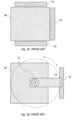
- the monitor 11 In this orientation, the monitor 11 must be situated at a sufficient distance from the instrument in order to pass the corners of the instrument during rotation, as illustrated by the dashed circle. Such a configuration would result in the monitor requiring significant more space than a single monitor attached directly to the front of the instrument. Having the monitor hanging at a distance from the instrument face also carries additional risk of damage to the monitor or to a person navigating around the instrument. Both the use of precious office space and the potential for damage are disadvantages of this solution.
- Fig. 2 illustrating an isometric schematic overall view of an exemplary implementation of the present disclosure, having a single monitor 21 positioned on the surface of one side of the instrument 20, the monitor being attached to the instrument by a connecting bar or arm 27.
- the instrument 20 may be positioned in a fixed position on a stable surface such as the floor, a table, or a desktop 24.
- the arm 27 is fastened in this exemplary implementation, at one end to the top of the instrument by means of a pivot bearing 26, such that it is free to rotate.
- the other end of the arm 27 is attached to the monitor 21.
- the monitor 21 is able to be rotated to position 21', where it will be flush on another face of the instrument, yet without having collided with the corner of the instrument as it is rotated.
- Figs. 3A and 3B show a mechanism of an exemplary implementation of the instrument of Fig. 2 , enabling the monitor 31 to swivel around the instrument in a manner which enables the monitor to clear the corner of the instrument, and yet keeps the monitor flush with the face when the rotation of the monitor positions the monitor opposite a face.
- the system enables rotation of the monitor to either or both sides of the original position.
- the rotation mechanism may allow the arm to rotate over 360 degrees, allowing the monitor to be viewed from any side of the instrument.
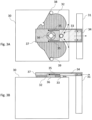
- Fig. 3A illustrating how the monitor 31 can be swiveled around a rotary bearing 36 by an extendible arm 37.
- the system also comprises a cam form 32 mounted on the instrument, whose profile is followed by a cam follower 33.
- the cam 32 may be fixedly attached to the top or the bottom of the instrument 30.
- the monitor rotating mechanism is shown mounted on the top of the instrument, though it is to be understood that this is only one option, and that it could also be mounted on the bottom, or even on both top and bottom.
- the monitor is attached by means of the extendible arm 37 to the rotary bearing 36 mounted on the top of the instrument, such that the monitor can swing around the instrument on the end of the arm 37.
- the arm 37 is extendible such that as the monitor approaches the protruding corner of the instrument, the arm can be extended such that the monitor does not hit the corner of the instrument.
- the outer extendible part of the arm 34 is attached to the inner part of the arm by means of spring elements 35, which generate a tensional force between the two parts of the arm, such that the spring elements tend to shorten the length of arm, if not prevented from doing so by an external element.
- the cam follower 33 attached to the outer extendible part 34 of the arm 37, is such an element, and as the arm and monitor are rotated, the cam follower 33 runs along the surface profile of the cam 32, which is mounted fixedly on the instrument.
- the cam profile is shaped such that when the monitor is located at the front side of the instrument, the cam follower is in a depression of the cam profile, which is the closest point of the cam profile in that sector of the cam, to the bearing 36, the distance from the cam follower 33 to the bearing 36, in conjunction with the lengths of the two parts of the arm, being such that the monitor 31 sits essentially on or close to the face of the instrument. This is a position of minimal potential energy of the spring system, which operates to pull the monitor towards the bearing.
- the cam profile Moving on either side away from the cam depression, the cam profile has a lobe extending out towards the corner of the instrument, the distance from the bearing axis to the furthermost point of the lobe being such that the cam follower 33 pushes the outer section of the extendable arm as it reaches the corner, sufficiently that the monitor just traverses the corner.
- the cam profile 32 is shaped such that after the monitor has traversed the corner, the cam follower 33 is again allowed to move closer to the bearing until it reaches a second depression 38 in the cam profile which is positioned at a distance from the bearing axis such that the monitor sits on or close to the side face of the instrument.
- the cam generally has bilateral symmetry such that a similar profile is found on the opposite side of the instrument with the second depression 39 causing the monitor to sit on the opposite face.
- the aligned positions of depression 38, 39 may be located at other than 90° from the front depression 33.
- Fig. 3A three potential positions of the cam follower are shown. In addition to the position in which cam follower 33 is positioned, movement to either the right or left will result in the cam follower following an outwardly arced trajectory so that the monitor avoids the corners of the instrument, and coming to rest in either of two positions represented by dotted circles 38 or 39.
- the present illustration is one exemplary embodiment of the disclosure. In some implementations, alternate shape configurations of the cam 32 may be used, such that the monitor has further stable positions and viewing angles.
- FIG. 3B showing a side view of the implementation of Fig. 3A .
- This view illustrates how the various components are connected and attached.
- the rotary bearing 36 is fixably attached to the instrument 30, and the extendable arm 37 rotates around the bearing.
- the outer extendable part 34 of the extendable arm 37 is shown, the outer part 34 sliding along a slot along the length of the inner part of the extendible arm which is radially static relative to the rotary bearing.
- This arrangement for providing the radial or longitudinal sliding motion is only one suggested implementation, and any other suitable arrangement is also feasible, such as a pair of tubes, one sliding inside the other (not shown in the drawings).
- the springs 35 should be selected such that they have sufficient tension to hold the monitor securely in place, but are able to be extended in order to move the monitor outwards away from the rotary bearing, without undue effort.
- the pins that attach the outer extendible part 34 to the inner part of the arm 37 allow longitudinal movement or sliding of the outer extendable part 34 and the monitor relative to the inner arm 37, as shown by the dotted arrow, as the cam follower 33 moves laterally around the cam 32, moving the monitor with it.
- Figs. 4A and 4B illustrating the cam mechanism in operation as the monitor 31 is rotated around the pivot bearing 36 on the top of the instrument 30.
- the outer section 34 of the arm holding the monitor 31 is attached to the inner section of the arm 37 by means of a set of springs 35 or other tensioning mechanism.
- the cam follower 33 rides the cam profile 32 pushing the outer section of the arm 34 and hence also the monitor 31 further from the pivot 36, stretching the springs 35 as the monitor rotates in order to keep the cam follower in contact with the cam profile.
- the trajectory of the monitor's movement is controlled by the shape of the cam 32, and by the movement of the cam follower 33 along the edge of the cam.
- the cam follower 33 is fixedly attached to the outer extendible part 34, the motion of the outer extendible part 34, and thus of the monitor 31, is constrained by the path of the cam follower 33 along the profile of the cam 32.
- the motion of the arm 37 is limited to rotation around the rotary bearing 36.
- the longitudinal motion of the monitor away from the instrument is enabled because of stretching of the springs 35, that allows the outer arm section 34 to slide relative to the arm 37.
- the cam may be fashioned in any number of useful shapes that fit the shape of the instrument and accomplish the desired movement of the monitor or other attached element.
- embodiments of the present disclosure have focused on the movable attachment of a vertical monitor to a desktop instrument, it is understood that embodiments of the disclosed cam follower and cam mechanism could be applied to any number of other situations. The same mechanism could be applied to any piece of equipment or tool requiring that one component be held in several rotatable positions relative to the main body.
Landscapes
- Engineering & Computer Science (AREA)
- General Engineering & Computer Science (AREA)
- Mechanical Engineering (AREA)
- A Measuring Device Byusing Mechanical Method (AREA)
- Devices For Indicating Variable Information By Combining Individual Elements (AREA)
- Details Of Measuring And Other Instruments (AREA)
Description
- The present invention relates to the field of desktop instrumentation with a monitor attached such that it can be viewed from more than one side of the instrument.
- There exist instruments having a monitor screen, in which it would be useful to provide visual access to the information displayed on the monitor from more than one direction. In particular, it would be useful while making adjustments to the instrument or on a subject for whom the instrument is operating, to be able to see the information on the monitor from more than one side of the instrument. This is particularly advantageous for performing ophthalmic or optometric measurements on a subject, where, for instance, the practitioner may like to sit by the side of the patient to check if he/she is sitting correctly at the machine with the chin and forehead in the correct position, whilst viewing information on the monitor. Depending on the geometry of the room, sometimes one side would be preferable and sometimes the opposite side. Alternatively, the practitioner may prefer to sit opposite the patient, in front of the machine. Prior art instruments having multiple monitors, such as one on each side, are known, such that the viewing screen may be viewed from several sides. An obvious drawback of such instruments is the cost of several monitors. Another potential solution is to rotate or swivel a single monitor around the corners of the instrument in order that it be viewable from multiple directions. The disadvantage of this option is that, to easily clear the corners of the instrument, the monitor needs to be attached to an arm of length that would leave the monitor positioned at a distance from the sides of the instrument. The distance between the monitor and the equipment may predispose the monitor to accidental impact, resulting in damage to the monitor, the person, or the instrument.
- There therefore exists a need for a solution which overcomes at least some of the disadvantages of prior art systems and methods.
- The disclosures of any publications mentioned in this specification, or in continuation or derivative applications thereof, are hereby incorporated by reference, each in its entirety. Document
CA 1 195 670 A discloses a similar mechanism for rotating a monitor. - The present disclosure provides new exemplary systems for an instrument having a single monitor screen, switchably positionable at multiple side faces of the instrument, without protruding from the instrument significantly more than the thickness of the monitor. The system utilizes a rotation mechanism that enables a monitor to be rotated between at least some of the side faces of the instrument, to negotiate the corners of the instrument, and to be parked at stable positions with respect to the side faces of the geometrically shaped instrument to which the monitor is attached. This is achieved by causing the monitor to follow the outer profile of a specially shaped cam fixedly mounted on the instrument in a plane generally parallel to a plane of rotation desired of the monitor, and generally perpendicular to the planes of the faces of the instrument, if the instrument is of the usual rectangular shape. The profile is shaped, having protruding sections and depressions or hollows, such that the protruding sections cause the monitor to move further away from the instrument as it passes the corners of the instrument, and the depressions or hollows in the cam profile, enable the monitor to move closer to the instrument as it reaches the faces of the instrument. The monitor is attached to an arm assembly, having a pivot bearing, enabling the arm assembly to rotate around the instrument. The arm assembly is made up of two parts - a longitudinally inner part in which the pivot bearing is mounted, and an outer part which slides longitudinally relative to the inner part, and to which the monitor is mounted. A spring mechanism attached between the inner and outer parts of the arm assembly, exerts an inwardly directed tensional force on the outer part of the arm assembly, attempting to pull it inwards towards the pivot joint. The inward motion of the outer part of the arm assembly is controlled by a cam follower, which can conveniently be a pin attached to the outer part of the arm assembly, and which follows the profile of the cam. In order to reduce friction, the pin can have a bearing fitted to it, such as a roller or needle or sleeve bearing, and all references in this disclosure to the term pin in relation to the cam follower, are intended to include such alternatives, and not to be limited only to a pin. The inwardly directed force ensures that the pin remains in contact with the cam profile and follows it as the arm assembly is rotated. As the arm assembly is rotated, the pin in the arm assembly follows the outer profile of the cam, and moves the monitor outwards to round the corners of the instrument. As the monitor passes positions parallel to the faces of the instrument, the monitor is pulled back inwards towards the instrument face.
- The cam profile is shaped such that, when the cam follower reaches a new equilibrium point on the cam at one of the cam profile depressions, i.e., a position of minimum potential energy of the spring mechanism, the monitor concomitantly comes to rest at a position parallel and close to another side of the instrument. In this manner, the monitor may be easily positioned on two or three sides of the instrument in resting positions that bring the monitor close to the instrument.
- It is to be understood that although the systems described in this disclosure are most usually used for enabling a monitor to negotiate around a corner of an instrument, and this is the situation in which the systems are generally described in this disclosure, such mechanisms can also be used to ensure that the monitor does not hit any projection extending beyond the surface of the instrument at locations other than the corner, and the systems are intended to cover all such projecting features, whether corners or other obstacles. The systems are also thuswise claimed, to include avoidance of all such obstructions.
- One exemplary implementation involves a mechanism for rotating a monitor around an instrument, the mechanism comprising:
- (i) a cam fixedly mounted on the instrument in a plane generally parallel to the plane of rotation of the monitor, the outer profile of the cam having at least one lobe directed towards projecting feature of the instrument,
- (ii) an extendible arm assembly comprising an outer section attached to the monitor, and an inner section attached to the instrument by means of a rotary bearing, the outer section of the extendible assembly arm being slidingly attached to the inner section of the extendible assembly arm, and having a spring mechanism, adapted to apply a tensional force to the outer section in the direction towards the rotary bearing, and
- (iii) a cam follower attached to the outer section of the extendible arm assembly, such that as the extendible arm assembly is rotated, the cam follower traces the outer profile of the cam, thereby causing the outer section of the extendible arm also to trace the outer profile of the cam.
- In such a mechanism, the projecting feature may be a corner of the instrument.
- Furthermore, the cam follower may be a pin or a bearing, adapted to slide or roll along the outer profile of the cam. In either of the above cases, the outer profile of the cam may further comprise at least one depression positioned closer to the rotary bearing than the regions on either side of the depression, the depression being positioned such that when the extendible arm assembly is at an angle that passes through the depression, the monitor is positioned along a side of the instrument, and in close proximity to the side of the instrument. In this disclosure, the term depression may be understood as a gradual indentation of the outer profile of the cam relative to the surrounding parts of the profile either side of the indentation.
- In any of the above mentioned mechanisms, the distance of the outer edge of the cam lobe from the rotary bearing may be such that when the extendible arm assembly is at an angle that passes through the projecting feature of the instrument, the monitor is positioned beyond the corner of the instrument.
- Furthermore, the lobe may be such that a line between the rotary bearing and the furthest point from the rotary bearing to the outer edge of the cam lobe, passes through or close to the projecting feature of the instrument.
- The extendible arm assembly may comprise two plates connected such that one slides along the other, or it may comprise two cylindrical elements connected such that one slides within the other.
- Embodiments of the present disclosure will be understood and appreciated more fully from the following detailed description, taken in conjunction with the drawings in which:
-
Figs.1A-B show prior art solutions for viewing the monitor of an instrument from different angles; -
Fig. 2 illustrates an isometric view of an exemplary implementation of the monitor arrangement as described in the current disclosure; -
Figs. 3A-B depict the elements of an exemplary implementation of the monitor positioner in plan-view (Fig. 3A ) and from the side elevation (Fig. 3B ); and -
Figs. 4A-B illustrate two positions of a monitor and its attaching arm, as the monitor moves around the corner of an instrument by means of a cam mechanism. - Reference is now made to
Fig. 1A , showing a top view of a prior art configuration of aninstrument 10 havingmonitors 11 attached to several of its faces, such that it can be viewed from those several faces. Having several monitors, each attached to one side of the instrument, provides the necessary ability to view the output of the instrument from multiple angles. This solution has the obvious disadvantages of cost.Fig. 1B illustrates another prior art solution, in which amonitor 11 is rotated around aninstrument 10 by means of a connectingarm 12 extending between the monitor and the instrument, and which rotates around a single fixedpoint 13 positioned near the center of the instrument, equidistant from opposite sides of the instrument. In this orientation, themonitor 11 must be situated at a sufficient distance from the instrument in order to pass the corners of the instrument during rotation, as illustrated by the dashed circle. Such a configuration would result in the monitor requiring significant more space than a single monitor attached directly to the front of the instrument. Having the monitor hanging at a distance from the instrument face also carries additional risk of damage to the monitor or to a person navigating around the instrument. Both the use of precious office space and the potential for damage are disadvantages of this solution. - Reference is now made to
Fig. 2 , illustrating an isometric schematic overall view of an exemplary implementation of the present disclosure, having asingle monitor 21 positioned on the surface of one side of theinstrument 20, the monitor being attached to the instrument by a connecting bar orarm 27. Theinstrument 20 may be positioned in a fixed position on a stable surface such as the floor, a table, or adesktop 24. Thearm 27 is fastened in this exemplary implementation, at one end to the top of the instrument by means of a pivot bearing 26, such that it is free to rotate. The other end of thearm 27 is attached to themonitor 21. As will be illustrated in connection withFigs. 3A and 3B , using the novel features of the present disclosure, themonitor 21 is able to be rotated to position 21', where it will be flush on another face of the instrument, yet without having collided with the corner of the instrument as it is rotated. - Reference is now made to
Figs. 3A and 3B , which show a mechanism of an exemplary implementation of the instrument ofFig. 2 , enabling themonitor 31 to swivel around the instrument in a manner which enables the monitor to clear the corner of the instrument, and yet keeps the monitor flush with the face when the rotation of the monitor positions the monitor opposite a face. The system enables rotation of the monitor to either or both sides of the original position. The rotation mechanism may allow the arm to rotate over 360 degrees, allowing the monitor to be viewed from any side of the instrument. - Reference is first made to
Fig. 3A , illustrating how themonitor 31 can be swiveled around a rotary bearing 36 by anextendible arm 37. The system also comprises acam form 32 mounted on the instrument, whose profile is followed by acam follower 33. Thecam 32 may be fixedly attached to the top or the bottom of theinstrument 30. In the examples illustrated in this disclosure, the monitor rotating mechanism is shown mounted on the top of the instrument, though it is to be understood that this is only one option, and that it could also be mounted on the bottom, or even on both top and bottom. The monitor is attached by means of theextendible arm 37 to the rotary bearing 36 mounted on the top of the instrument, such that the monitor can swing around the instrument on the end of thearm 37. Thearm 37 is extendible such that as the monitor approaches the protruding corner of the instrument, the arm can be extended such that the monitor does not hit the corner of the instrument. The outer extendible part of thearm 34, is attached to the inner part of the arm by means ofspring elements 35, which generate a tensional force between the two parts of the arm, such that the spring elements tend to shorten the length of arm, if not prevented from doing so by an external element. Thecam follower 33 attached to the outerextendible part 34 of thearm 37, is such an element, and as the arm and monitor are rotated, thecam follower 33 runs along the surface profile of thecam 32, which is mounted fixedly on the instrument. The cam profile is shaped such that when the monitor is located at the front side of the instrument, the cam follower is in a depression of the cam profile, which is the closest point of the cam profile in that sector of the cam, to thebearing 36, the distance from thecam follower 33 to thebearing 36, in conjunction with the lengths of the two parts of the arm, being such that themonitor 31 sits essentially on or close to the face of the instrument. This is a position of minimal potential energy of the spring system, which operates to pull the monitor towards the bearing. Moving on either side away from the cam depression, the cam profile has a lobe extending out towards the corner of the instrument, the distance from the bearing axis to the furthermost point of the lobe being such that thecam follower 33 pushes the outer section of the extendable arm as it reaches the corner, sufficiently that the monitor just traverses the corner. Thecam profile 32 is shaped such that after the monitor has traversed the corner, thecam follower 33 is again allowed to move closer to the bearing until it reaches asecond depression 38 in the cam profile which is positioned at a distance from the bearing axis such that the monitor sits on or close to the side face of the instrument. For symmetrically shaped instruments, the cam generally has bilateral symmetry such that a similar profile is found on the opposite side of the instrument with thesecond depression 39 causing the monitor to sit on the opposite face. If the instrument is not rectilinear, the aligned positions ofdepression front depression 33. InFig. 3A , three potential positions of the cam follower are shown. In addition to the position in whichcam follower 33 is positioned, movement to either the right or left will result in the cam follower following an outwardly arced trajectory so that the monitor avoids the corners of the instrument, and coming to rest in either of two positions represented bydotted circles cam 32 may be used, such that the monitor has further stable positions and viewing angles. - Reference is now made to
Fig. 3B , showing a side view of the implementation ofFig. 3A . This view illustrates how the various components are connected and attached. Therotary bearing 36 is fixably attached to theinstrument 30, and theextendable arm 37 rotates around the bearing. In this embodiment the outerextendable part 34 of theextendable arm 37 is shown, theouter part 34 sliding along a slot along the length of the inner part of the extendible arm which is radially static relative to the rotary bearing. This arrangement for providing the radial or longitudinal sliding motion is only one suggested implementation, and any other suitable arrangement is also feasible, such as a pair of tubes, one sliding inside the other (not shown in the drawings). Thesprings 35 should be selected such that they have sufficient tension to hold the monitor securely in place, but are able to be extended in order to move the monitor outwards away from the rotary bearing, without undue effort. The pins that attach the outerextendible part 34 to the inner part of thearm 37 allow longitudinal movement or sliding of the outerextendable part 34 and the monitor relative to theinner arm 37, as shown by the dotted arrow, as thecam follower 33 moves laterally around thecam 32, moving the monitor with it. - Reference is now made to
Figs. 4A and 4B , illustrating the cam mechanism in operation as themonitor 31 is rotated around the pivot bearing 36 on the top of theinstrument 30. Theouter section 34 of the arm holding themonitor 31 is attached to the inner section of thearm 37 by means of a set ofsprings 35 or other tensioning mechanism. As the arm rotates away from its position with the monitor closest to the instrument, thecam follower 33 rides thecam profile 32 pushing the outer section of thearm 34 and hence also themonitor 31 further from thepivot 36, stretching thesprings 35 as the monitor rotates in order to keep the cam follower in contact with the cam profile. The trajectory of the monitor's movement is controlled by the shape of thecam 32, and by the movement of thecam follower 33 along the edge of the cam. Because thecam follower 33 is fixedly attached to the outerextendible part 34, the motion of the outerextendible part 34, and thus of themonitor 31, is constrained by the path of thecam follower 33 along the profile of thecam 32. The motion of thearm 37 is limited to rotation around therotary bearing 36. The longitudinal motion of the monitor away from the instrument is enabled because of stretching of thesprings 35, that allows theouter arm section 34 to slide relative to thearm 37. As is seen inFig. 4B , when the cam follower reaches the indentation on the cam, themonitor 31 is arranged to come to rest parallel to an adjacent side of theinstrument 30 from its original position. Rotation of the monitor in the opposite direction will result in the monitor being positioned on the opposite face of the instrument to the position in 4B. Depending on the desired positions of the monitor, in other embodiments the cam may be fashioned in any number of useful shapes that fit the shape of the instrument and accomplish the desired movement of the monitor or other attached element. - Whereas embodiments of the present disclosure have focused on the movable attachment of a vertical monitor to a desktop instrument, it is understood that embodiments of the disclosed cam follower and cam mechanism could be applied to any number of other situations. The same mechanism could be applied to any piece of equipment or tool requiring that one component be held in several rotatable positions relative to the main body.
Claims (9)
- A mechanism for rotating a monitor around an instrument (10), the mechanism comprising:an extendible arm (37) assembly comprising an outer section (34) attached to the monitor (11),and an inner section attached to the instrument by means of a rotary bearing (36),characterized in that the mechanism comprises:a cam (32) fixedly mounted on the instrument in a plane generally parallel to the plane of rotation of the monitor, the outer profile of the cam having at least one lobe directed towards a projecting feature of the instrument, the outer section of the extendible assembly arm being slidingly attached to the inner section of the extendible assembly arm, and having a spring mechanism adapted to apply a tensional force to the outer section in the direction towards the rotary bearing; anda cam follower (33) attached to the outer section of the extendible arm assembly, such that as the extendible arm assembly is rotated, the cam follower traces the outer profile of the cam, thereby causing the outer section of the extendible arm also to trace the outer profile of the cam.
- The mechanism according to claim 1 wherein the cam follower is a pin, adapted to slide along the outer profile of the cam.
- The mechanism according to claim 1 wherein the cam follower is a bearing, adapted to roll along the outer profile of the cam.
- The mechanism according to any of claims 1 to 3, wherein the outer profile of the cam further comprises at least one depression positioned closer to the rotary bearing than the regions on either side of the depression, the depression being positioned such that when the extendible arm assembly is at an angle that passes through the depression, the monitor is positioned along a side of the instrument, and in close proximity to the side of the instrument.
- The mechanism according to any of the previous claims, wherein the distance of the outer edge of the cam lobe from the rotary bearing is such that when the extendible arm assembly is at an angle that passes through the projecting feature of the instrument, the monitor is positioned beyond the projecting feature of the instrument.
- The mechanism according to any of the previous claims, wherein the lobe is such that a line between the rotary bearing and the furthest point from the rotary bearing to the outer edge of the cam lobe, passes through or close to the projecting feature of the instrument.
- The mechanism according to any of the previous claims, wherein the extendible arm assembly comprises two plates connected such that one slides along the other.
- The mechanism according to any of claims 1 to 6, wherein the extendible arm assembly comprises two cylindrical elements connected such that one slides within the other.
- The mechanism according to any of the previous claims, wherein the projecting feature of the instrument is a corner of the instrument.
Applications Claiming Priority (2)
| Application Number | Priority Date | Filing Date | Title |
|---|---|---|---|
| IL272902A IL272902B (en) | 2020-02-25 | 2020-02-25 | Device for rotating a flat monitor around an instrument |
| PCT/IB2021/051546 WO2021171198A1 (en) | 2020-02-25 | 2021-02-24 | Device for rotating a monitor around an instrument |
Publications (3)
| Publication Number | Publication Date |
|---|---|
| EP4111086A1 EP4111086A1 (en) | 2023-01-04 |
| EP4111086A4 EP4111086A4 (en) | 2023-10-25 |
| EP4111086B1 true EP4111086B1 (en) | 2025-04-23 |
Family
ID=72882662
Family Applications (1)
| Application Number | Title | Priority Date | Filing Date |
|---|---|---|---|
| EP21760628.4A Active EP4111086B1 (en) | 2020-02-25 | 2021-02-24 | Device for rotating a monitor around an instrument |
Country Status (6)
| Country | Link |
|---|---|
| US (1) | US20230003336A1 (en) |
| EP (1) | EP4111086B1 (en) |
| JP (1) | JP7684983B2 (en) |
| CN (1) | CN115715357B (en) |
| IL (1) | IL272902B (en) |
| WO (1) | WO2021171198A1 (en) |
Families Citing this family (1)
| Publication number | Priority date | Publication date | Assignee | Title |
|---|---|---|---|---|
| CN117869763B (en) * | 2024-03-13 | 2024-05-14 | 山西鑫德辉科技有限公司 | Intelligent manufacturing workshop monitoring device and monitoring method thereof |
Family Cites Families (20)
| Publication number | Priority date | Publication date | Assignee | Title |
|---|---|---|---|---|
| US1535658A (en) * | 1923-06-27 | 1925-04-28 | Wirt Company | Portable electric-light fixture |
| US2486248A (en) * | 1946-11-01 | 1949-10-25 | Berman Jack | Safety clothesline hook |
| CA1195670A (en) * | 1981-11-09 | 1985-10-22 | Alexander D. Karapita | Suspension system |
| EP0989479B1 (en) * | 1998-09-21 | 2004-06-02 | Hewlett-Packard Company, A Delaware Corporation | Rotatable display apparatus |
| CN100532911C (en) * | 2002-03-20 | 2009-08-26 | 维泰克公开有限公司 | Tiltable mountings for payloads |
| JP3595547B2 (en) * | 2002-08-22 | 2004-12-02 | シャープ株式会社 | Thin display device |
| JP4321845B2 (en) * | 2002-10-24 | 2009-08-26 | 株式会社ホスピタルネット | Cabinet that also serves as a stand for image display equipment |
| US6736360B1 (en) * | 2003-01-27 | 2004-05-18 | Alcon, Inc. | Rotary jointed arm for a surgical tray |
| US7178469B2 (en) * | 2003-02-10 | 2007-02-20 | Roger Goza | Retractable multiposition furniture system |
| FR2867171B1 (en) * | 2004-03-05 | 2007-06-08 | Sidel Sa | CONVEYING DEVICE HAVING AN IMPROVED TRANSFER ARM |
| WO2006030487A1 (en) * | 2004-09-14 | 2006-03-23 | Fujitsu Limited | Display device |
| US7997211B2 (en) * | 2006-06-12 | 2011-08-16 | Steelcase Inc. | Wall mounted workstation |
| US20080100052A1 (en) * | 2006-10-27 | 2008-05-01 | Fontaine Spray Suppression Company | Ramping Mudflap Assembly |
| JP4888289B2 (en) * | 2007-09-06 | 2012-02-29 | 富士通株式会社 | Connecting device and electronic device |
| US20090158601A1 (en) * | 2007-12-19 | 2009-06-25 | Herschel James Davis | Creative Designing Apparatus |
| US8601739B2 (en) * | 2011-09-02 | 2013-12-10 | Siemens Rail Automation Corporation | Gate arm saver |
| GB201201903D0 (en) * | 2012-02-03 | 2012-03-21 | Amsafe Bridport Ltd | Mounting assembly |
| CN204538626U (en) * | 2015-05-06 | 2015-08-05 | 陕西理工学院 | Horizontal two division deicing high-voltage power transmission line machine clamping obstacle crossing device |
| CN105955409A (en) * | 2016-06-08 | 2016-09-21 | 卢波 | Spacing structure and mobile terminal handheld device comprising the same |
| CN108789453A (en) * | 2018-08-17 | 2018-11-13 | 成都跟驰科技有限公司 | The touch screen control system of automobile with folding mechanism arm |
-
2020
- 2020-02-25 IL IL272902A patent/IL272902B/en not_active IP Right Cessation
-
2021
- 2021-02-24 CN CN202180022342.1A patent/CN115715357B/en active Active
- 2021-02-24 WO PCT/IB2021/051546 patent/WO2021171198A1/en not_active Ceased
- 2021-02-24 EP EP21760628.4A patent/EP4111086B1/en active Active
- 2021-02-24 JP JP2022550980A patent/JP7684983B2/en active Active
- 2021-02-24 US US17/802,169 patent/US20230003336A1/en not_active Abandoned
Also Published As
| Publication number | Publication date |
|---|---|
| CN115715357A (en) | 2023-02-24 |
| IL272902B (en) | 2020-09-30 |
| CN115715357B (en) | 2026-06-30 |
| US20230003336A1 (en) | 2023-01-05 |
| WO2021171198A1 (en) | 2021-09-02 |
| JP7684983B2 (en) | 2025-05-28 |
| EP4111086A4 (en) | 2023-10-25 |
| JP2023529048A (en) | 2023-07-07 |
| EP4111086A1 (en) | 2023-01-04 |
Similar Documents
| Publication | Publication Date | Title |
|---|---|---|
| US7988357B2 (en) | X-ray system | |
| CN111207282B (en) | Method and system for pivotable tablet computer stand | |
| EP1688091B9 (en) | C-arm holding apparatus and X-ray diagnostic apparatus | |
| CN110376741B (en) | Head Mounted Device Stands and Head Mounted Devices | |
| US4209706A (en) | Fluoroscopic apparatus mounting fixture | |
| CN108836372B (en) | Method and system for compact integrated monitor arm for imaging device | |
| US6309102B1 (en) | Positioner for an x-ray examination apparatus | |
| JP2009033308A (en) | Head mounted display | |
| US12343035B2 (en) | Needle guiding bracket with adjustable angles | |
| EP2073708B1 (en) | Digital radiography imaging system | |
| EP4111086A1 (en) | Device for rotating a monitor around an instrument | |
| US20210177525A1 (en) | Navigated instrument for use in robotic guided surgery | |
| US10197218B2 (en) | Medical apparatus, and display supporting structure and arm structure used in the same | |
| CN112494141B (en) | Image-guided interventional surgery navigation treatment equipment | |
| EP3860499B1 (en) | Movable rack arm with counterbalance spring for contoured non-linear force transfer | |
| CN113456227B (en) | Image registration device | |
| KR20200007303A (en) | X-ray device | |
| CN214699867U (en) | X-ray production apparatus and display support thereof | |
| JP2019084327A (en) | X-ray diagnostic apparatus | |
| CN211118353U (en) | Base device for precision adjustment of vision camera | |
| CN221654563U (en) | End effector for hip joint replacement and orthopedic robot | |
| CN210158613U (en) | End cover of medical bed, bedstead subassembly and medical bed | |
| CN216408232U (en) | Bearing module | |
| KR102813884B1 (en) | Connector module with two-way rotation | |
| KR102813900B1 (en) | A Chair |
Legal Events
| Date | Code | Title | Description |
|---|---|---|---|
| STAA | Information on the status of an ep patent application or granted ep patent |
Free format text: STATUS: THE INTERNATIONAL PUBLICATION HAS BEEN MADE |
|
| PUAI | Public reference made under article 153(3) epc to a published international application that has entered the european phase |
Free format text: ORIGINAL CODE: 0009012 |
|
| STAA | Information on the status of an ep patent application or granted ep patent |
Free format text: STATUS: REQUEST FOR EXAMINATION WAS MADE |
|
| 17P | Request for examination filed |
Effective date: 20220926 |
|
| AK | Designated contracting states |
Kind code of ref document: A1 Designated state(s): AL AT BE BG CH CY CZ DE DK EE ES FI FR GB GR HR HU IE IS IT LI LT LU LV MC MK MT NL NO PL PT RO RS SE SI SK SM TR |
|
| DAV | Request for validation of the european patent (deleted) | ||
| DAX | Request for extension of the european patent (deleted) | ||
| A4 | Supplementary search report drawn up and despatched |
Effective date: 20230925 |
|
| RIC1 | Information provided on ipc code assigned before grant |
Ipc: F16M 11/04 20060101ALI20230919BHEP Ipc: A47B 37/00 20060101ALI20230919BHEP Ipc: F16M 13/00 20060101ALI20230919BHEP Ipc: F16M 11/00 20060101AFI20230919BHEP |
|
| RIC1 | Information provided on ipc code assigned before grant |
Ipc: F16M 13/02 20060101ALI20240528BHEP Ipc: F16M 11/08 20060101ALI20240528BHEP Ipc: F16M 11/04 20060101ALI20240528BHEP Ipc: A47B 37/00 20060101ALI20240528BHEP Ipc: F16M 13/00 20060101ALI20240528BHEP Ipc: F16M 11/00 20060101AFI20240528BHEP |
|
| GRAP | Despatch of communication of intention to grant a patent |
Free format text: ORIGINAL CODE: EPIDOSNIGR1 |
|
| STAA | Information on the status of an ep patent application or granted ep patent |
Free format text: STATUS: GRANT OF PATENT IS INTENDED |
|
| INTG | Intention to grant announced |
Effective date: 20241125 |
|
| GRAS | Grant fee paid |
Free format text: ORIGINAL CODE: EPIDOSNIGR3 |
|
| GRAA | (expected) grant |
Free format text: ORIGINAL CODE: 0009210 |
|
| STAA | Information on the status of an ep patent application or granted ep patent |
Free format text: STATUS: THE PATENT HAS BEEN GRANTED |
|
| AK | Designated contracting states |
Kind code of ref document: B1 Designated state(s): AL AT BE BG CH CY CZ DE DK EE ES FI FR GB GR HR HU IE IS IT LI LT LU LV MC MK MT NL NO PL PT RO RS SE SI SK SM TR |
|
| REG | Reference to a national code |
Ref country code: GB Ref legal event code: FG4D |
|
| REG | Reference to a national code |
Ref country code: CH Ref legal event code: EP |
|
| REG | Reference to a national code |
Ref country code: DE Ref legal event code: R096 Ref document number: 602021029646 Country of ref document: DE |
|
| REG | Reference to a national code |
Ref country code: IE Ref legal event code: FG4D |
|
| P01 | Opt-out of the competence of the unified patent court (upc) registered |
Free format text: CASE NUMBER: APP_22166/2025 Effective date: 20250509 |
|
| REG | Reference to a national code |
Ref country code: NL Ref legal event code: MP Effective date: 20250423 |
|
| PG25 | Lapsed in a contracting state [announced via postgrant information from national office to epo] |
Ref country code: NL Free format text: LAPSE BECAUSE OF FAILURE TO SUBMIT A TRANSLATION OF THE DESCRIPTION OR TO PAY THE FEE WITHIN THE PRESCRIBED TIME-LIMIT Effective date: 20250423 |
|
| REG | Reference to a national code |
Ref country code: AT Ref legal event code: MK05 Ref document number: 1788041 Country of ref document: AT Kind code of ref document: T Effective date: 20250423 |
|
| PG25 | Lapsed in a contracting state [announced via postgrant information from national office to epo] |
Ref country code: FI Free format text: LAPSE BECAUSE OF FAILURE TO SUBMIT A TRANSLATION OF THE DESCRIPTION OR TO PAY THE FEE WITHIN THE PRESCRIBED TIME-LIMIT Effective date: 20250423 Ref country code: PT Free format text: LAPSE BECAUSE OF FAILURE TO SUBMIT A TRANSLATION OF THE DESCRIPTION OR TO PAY THE FEE WITHIN THE PRESCRIBED TIME-LIMIT Effective date: 20250825 Ref country code: ES Free format text: LAPSE BECAUSE OF FAILURE TO SUBMIT A TRANSLATION OF THE DESCRIPTION OR TO PAY THE FEE WITHIN THE PRESCRIBED TIME-LIMIT Effective date: 20250423 |
|
| REG | Reference to a national code |
Ref country code: LT Ref legal event code: MG9D |
|
| PG25 | Lapsed in a contracting state [announced via postgrant information from national office to epo] |
Ref country code: GR Free format text: LAPSE BECAUSE OF FAILURE TO SUBMIT A TRANSLATION OF THE DESCRIPTION OR TO PAY THE FEE WITHIN THE PRESCRIBED TIME-LIMIT Effective date: 20250724 Ref country code: NO Free format text: LAPSE BECAUSE OF FAILURE TO SUBMIT A TRANSLATION OF THE DESCRIPTION OR TO PAY THE FEE WITHIN THE PRESCRIBED TIME-LIMIT Effective date: 20250723 |
|
| PG25 | Lapsed in a contracting state [announced via postgrant information from national office to epo] |
Ref country code: PL Free format text: LAPSE BECAUSE OF FAILURE TO SUBMIT A TRANSLATION OF THE DESCRIPTION OR TO PAY THE FEE WITHIN THE PRESCRIBED TIME-LIMIT Effective date: 20250423 |
|
| PG25 | Lapsed in a contracting state [announced via postgrant information from national office to epo] |
Ref country code: BG Free format text: LAPSE BECAUSE OF FAILURE TO SUBMIT A TRANSLATION OF THE DESCRIPTION OR TO PAY THE FEE WITHIN THE PRESCRIBED TIME-LIMIT Effective date: 20250423 |
|
| PG25 | Lapsed in a contracting state [announced via postgrant information from national office to epo] |
Ref country code: HR Free format text: LAPSE BECAUSE OF FAILURE TO SUBMIT A TRANSLATION OF THE DESCRIPTION OR TO PAY THE FEE WITHIN THE PRESCRIBED TIME-LIMIT Effective date: 20250423 |
|
| PG25 | Lapsed in a contracting state [announced via postgrant information from national office to epo] |
Ref country code: AT Free format text: LAPSE BECAUSE OF FAILURE TO SUBMIT A TRANSLATION OF THE DESCRIPTION OR TO PAY THE FEE WITHIN THE PRESCRIBED TIME-LIMIT Effective date: 20250423 |
|
| PG25 | Lapsed in a contracting state [announced via postgrant information from national office to epo] |
Ref country code: RS Free format text: LAPSE BECAUSE OF FAILURE TO SUBMIT A TRANSLATION OF THE DESCRIPTION OR TO PAY THE FEE WITHIN THE PRESCRIBED TIME-LIMIT Effective date: 20250723 |
|
| PG25 | Lapsed in a contracting state [announced via postgrant information from national office to epo] |
Ref country code: IS Free format text: LAPSE BECAUSE OF FAILURE TO SUBMIT A TRANSLATION OF THE DESCRIPTION OR TO PAY THE FEE WITHIN THE PRESCRIBED TIME-LIMIT Effective date: 20250823 |
|
| PG25 | Lapsed in a contracting state [announced via postgrant information from national office to epo] |
Ref country code: LV Free format text: LAPSE BECAUSE OF FAILURE TO SUBMIT A TRANSLATION OF THE DESCRIPTION OR TO PAY THE FEE WITHIN THE PRESCRIBED TIME-LIMIT Effective date: 20250423 |
|
| PG25 | Lapsed in a contracting state [announced via postgrant information from national office to epo] |
Ref country code: DK Free format text: LAPSE BECAUSE OF FAILURE TO SUBMIT A TRANSLATION OF THE DESCRIPTION OR TO PAY THE FEE WITHIN THE PRESCRIBED TIME-LIMIT Effective date: 20250423 Ref country code: SM Free format text: LAPSE BECAUSE OF FAILURE TO SUBMIT A TRANSLATION OF THE DESCRIPTION OR TO PAY THE FEE WITHIN THE PRESCRIBED TIME-LIMIT Effective date: 20250423 |
|
| PG25 | Lapsed in a contracting state [announced via postgrant information from national office to epo] |
Ref country code: CZ Free format text: LAPSE BECAUSE OF FAILURE TO SUBMIT A TRANSLATION OF THE DESCRIPTION OR TO PAY THE FEE WITHIN THE PRESCRIBED TIME-LIMIT Effective date: 20250423 |
|
| PG25 | Lapsed in a contracting state [announced via postgrant information from national office to epo] |
Ref country code: EE Free format text: LAPSE BECAUSE OF FAILURE TO SUBMIT A TRANSLATION OF THE DESCRIPTION OR TO PAY THE FEE WITHIN THE PRESCRIBED TIME-LIMIT Effective date: 20250423 |
|
| REG | Reference to a national code |
Ref country code: DE Ref legal event code: R097 Ref document number: 602021029646 Country of ref document: DE |
|
| PG25 | Lapsed in a contracting state [announced via postgrant information from national office to epo] |
Ref country code: SK Free format text: LAPSE BECAUSE OF FAILURE TO SUBMIT A TRANSLATION OF THE DESCRIPTION OR TO PAY THE FEE WITHIN THE PRESCRIBED TIME-LIMIT Effective date: 20250423 |
|
| PG25 | Lapsed in a contracting state [announced via postgrant information from national office to epo] |
Ref country code: IT Free format text: LAPSE BECAUSE OF FAILURE TO SUBMIT A TRANSLATION OF THE DESCRIPTION OR TO PAY THE FEE WITHIN THE PRESCRIBED TIME-LIMIT Effective date: 20250423 |
|
| PLBE | No opposition filed within time limit |
Free format text: ORIGINAL CODE: 0009261 |
|
| STAA | Information on the status of an ep patent application or granted ep patent |
Free format text: STATUS: NO OPPOSITION FILED WITHIN TIME LIMIT |
|
| REG | Reference to a national code |
Ref country code: CH Ref legal event code: L10 Free format text: ST27 STATUS EVENT CODE: U-0-0-L10-L00 (AS PROVIDED BY THE NATIONAL OFFICE) Effective date: 20260304 |
|
| 26N | No opposition filed |
Effective date: 20260126 |
|
| PGFP | Annual fee paid to national office [announced via postgrant information from national office to epo] |
Ref country code: GB Payment date: 20260219 Year of fee payment: 6 |
|
| PGFP | Annual fee paid to national office [announced via postgrant information from national office to epo] |
Ref country code: DE Payment date: 20260217 Year of fee payment: 6 |
|
| PGFP | Annual fee paid to national office [announced via postgrant information from national office to epo] |
Ref country code: FR Payment date: 20260219 Year of fee payment: 6 |
|
| PG25 | Lapsed in a contracting state [announced via postgrant information from national office to epo] |
Ref country code: LT Free format text: LAPSE BECAUSE OF FAILURE TO SUBMIT A TRANSLATION OF THE DESCRIPTION OR TO PAY THE FEE WITHIN THE PRESCRIBED TIME-LIMIT Effective date: 20250423 |
|
| PG25 | Lapsed in a contracting state [announced via postgrant information from national office to epo] |
Ref country code: SE Free format text: LAPSE BECAUSE OF FAILURE TO SUBMIT A TRANSLATION OF THE DESCRIPTION OR TO PAY THE FEE WITHIN THE PRESCRIBED TIME-LIMIT Effective date: 20250423 |