EP4110680B1 - Antriebseinheit einer elektrischen hilfskraftlenkung für ein kraftfahrzeug - Google Patents
Antriebseinheit einer elektrischen hilfskraftlenkung für ein kraftfahrzeug Download PDFInfo
- Publication number
- EP4110680B1 EP4110680B1 EP21706888.1A EP21706888A EP4110680B1 EP 4110680 B1 EP4110680 B1 EP 4110680B1 EP 21706888 A EP21706888 A EP 21706888A EP 4110680 B1 EP4110680 B1 EP 4110680B1
- Authority
- EP
- European Patent Office
- Prior art keywords
- positioning
- housing
- control board
- drive unit
- control
- Prior art date
- Legal status (The legal status is an assumption and is not a legal conclusion. Google has not performed a legal analysis and makes no representation as to the accuracy of the status listed.)
- Active
Links
Images





Classifications
-
- B—PERFORMING OPERATIONS; TRANSPORTING
- B62—LAND VEHICLES FOR TRAVELLING OTHERWISE THAN ON RAILS
- B62D—MOTOR VEHICLES; TRAILERS
- B62D5/00—Power-assisted or power-driven steering
- B62D5/04—Power-assisted or power-driven steering electrical, e.g. using an electric servo-motor connected to, or forming part of, the steering gear
- B62D5/0403—Power-assisted or power-driven steering electrical, e.g. using an electric servo-motor connected to, or forming part of, the steering gear characterised by constructional features, e.g. common housing for motor and gear box
- B62D5/0406—Power-assisted or power-driven steering electrical, e.g. using an electric servo-motor connected to, or forming part of, the steering gear characterised by constructional features, e.g. common housing for motor and gear box including housing for electronic control unit
-
- H—ELECTRICITY
- H05—ELECTRIC TECHNIQUES NOT OTHERWISE PROVIDED FOR
- H05K—PRINTED CIRCUITS; CASINGS OR CONSTRUCTIONAL DETAILS OF ELECTRIC APPARATUS; MANUFACTURE OF ASSEMBLAGES OF ELECTRICAL COMPONENTS
- H05K5/00—Casings, cabinets or drawers for electric apparatus
- H05K5/0026—Casings, cabinets or drawers for electric apparatus provided with connectors and printed circuit boards [PCB], e.g. automotive electronic control units
- H05K5/0069—Casings, cabinets or drawers for electric apparatus provided with connectors and printed circuit boards [PCB], e.g. automotive electronic control units having connector relating features for connecting the connector pins with the PCB or for mounting the connector body with the housing
-
- H—ELECTRICITY
- H05—ELECTRIC TECHNIQUES NOT OTHERWISE PROVIDED FOR
- H05K—PRINTED CIRCUITS; CASINGS OR CONSTRUCTIONAL DETAILS OF ELECTRIC APPARATUS; MANUFACTURE OF ASSEMBLAGES OF ELECTRICAL COMPONENTS
- H05K7/00—Constructional details common to different types of electric apparatus
- H05K7/14—Mounting supporting structure in casing or on frame or rack
- H05K7/1422—Printed circuit boards receptacles, e.g. stacked structures, electronic circuit modules or box like frames
- H05K7/1427—Housings
- H05K7/1432—Housings specially adapted for power drive units or power converters
- H05K7/14322—Housings specially adapted for power drive units or power converters wherein the control and power circuits of a power converter are arranged within the same casing
Definitions
- the invention relates to a drive unit for an electric power steering system of a motor vehicle, comprising an electric motor with a stator housing to which a control housing is attached, in which a control board is arranged, and with a connecting unit attached to the stator housing, which has electrical connecting elements and at least one positioning element, wherein the connecting elements are electrically connected to the electric motor and to the control board and the positioning element cooperates with the control board for relative positioning, wherein the positioning element cooperates with the control housing for relative positioning.
- Motor vehicle steering systems with power assistance are known in the prior art, in which, in addition to the steering torque manually applied by the driver to the steering wheel, an auxiliary force is introduced into the steering train by an electro-mechanical auxiliary power assistance to support and relieve the driver, and if necessary also an additional steering angle.
- the auxiliary power is generated by means of an electric auxiliary drive, which has a drive unit with an electric motor, the rotor shaft of which is coupled to the steering train via an auxiliary power transmission.
- a generic drive unit is known in the state of the art, for example from DE 10 2018 216 744 A1
- This comprises a motor with a stator housing in which the stator or phase windings are mounted, and in which the rotor is rotatably mounted with the rotor shaft arranged in the axial direction.
- the electrical control of the motor is carried out by an electrical control circuit, which has electrical components arranged and connected on a control board, also referred to as a printed circuit board or PCB.
- This control board is arranged in a control housing, also referred to as a control or control board housing, which is connected to the stator housing to form a compact assembly, also referred to as a power pack.
- connection unit The electrical and mechanical connection between the phase windings of the motor and the control board is made via a connection unit. This is connected on the one hand to fixed to the stator housing and connected to the phase windings of the motor, and on the other hand connected to the control housing and connected to the control board.
- the connecting unit has positioning elements in the form of positioning pins that engage positively in corresponding receiving openings in the control board.
- the positioning elements thus interact with the control board in such a way that a positioning and alignment of the control board relative to the connecting unit, and thus to the stator housing, is created.
- the control board is protected in the control housing when installed.
- a disadvantage is that the control housing is not aligned or only inadequately aligned relative to the control board.
- the control housing is in turn attached to the stator housing or the connecting unit. Because the tolerances of the connections between the stator housing, connecting unit and control board add up with regard to the alignment of the control board relative to the control housing, the assembly of the control board can be made more difficult and there is an increased risk of damage during assembly.
- a drive unit of the type mentioned above is known in the prior art, for example from JP 2013 106376 A , JP 2018 125948 A , US 2015/222156 A1 , US 2014/125173 A1 or EP 1 955 927 A1
- JP 2013 106376 A JP 2018 125948 A
- US 2015/222156 A1 JP 2018 125948 A
- US 2015/222156 A1 JP 2018 125948 A
- US 2014/125173 A1 US 2014/125173 A1
- EP 1 955 927 A1 The disadvantage of all the designs described therein is that installation is complicated.
- a drive unit for an electric power steering system of a motor vehicle comprising an electric motor with a stator housing to which a control housing is attached, in which a control board is arranged, and with a connecting unit attached to the stator housing, which has electrical connecting elements and at least one positioning element, wherein the connecting elements are electrically connected to the electric motor and to the control board and the positioning element cooperates with the control board for relative positioning, wherein the positioning element cooperates with the control housing for relative positioning
- the invention provides that at least one positioning element protrudes further from the stator housing relative to another positioning element.
- the at least one positioning element that protrudes further is longer than the other positioning element(s) or than the connecting element(s).
- the longer positioning element is preferably at least 1 mm longer or at least 2 mm longer than the other positioning or connecting element.
- a positioning element preferably designed as a positioning pin, protrudes further axially, in the axial direction, it can be axially inserted into a corresponding positioning receptacle, preferably a receiving opening, while still enabling a relative orientation of the other positioning element(s) that are further back axially with respect to the mounting direction and do not yet engage in the corresponding positioning receptacles.
- the other positioning elements are automatically aligned with respect to the corresponding positioning receptacles and can be mounted by further axial movement. This can simplify assembly.
- the electric motor is arranged in the stator housing, which comprises a stator with stator or phase windings, in which a rotor with a rotor shaft lying in the axial direction is rotatably mounted.
- the connecting unit is positioned and fixed to the stator housing and provides at least one positioning element according to the invention, preferably a plurality of positioning elements.
- the positioning element is designed and configured to enable the precise alignment of both the control board and the control housing relative to the connecting unit.
- the control board and the control housing are each aligned directly on the positioning element and thus positioned and aligned parallel to one another on the same positioning element relative to the connecting unit, and not via a serial arrangement of connections as in the prior art. This avoids the unavoidable and potentially damaging addition of the tolerances of the serially arranged connections in the prior art, and ensures improved and more precise positioning of the control board and the control housing.
- the improved dimensional accuracy of the arrangement simplifies assembly, particularly in automated production.
- the relative orientation between the control housing and the positioning element is largely independent of tolerances, so that the inventive alignment of the control board on this positioning element a correspondingly precise alignment of the control board relative to the control housing is ensured.
- This reproducible, low-tolerance alignment simplifies assembly and reduces the risk of damage due to relative misalignment when inserting the control board into the control housing and when assembling the connections between the connection unit and the control board.
- the positioning element(s) according to the invention provide, for the first time, a common reference position for the alignment and orientation of the control housing and control board, whereby tolerance-related problems and the risk of damage during assembly can be reduced and largely avoided.
- the control housing can be fixed to the stator housing, for example by flange-mounting, for example by means of fastening bolts that are passed through corresponding fastening bores and screwed together. By providing a sufficiently large amount of play, the fixing can be achieved in the relative positioning defined by the positioning elements.
- the control housing can, for example, be fixed to the stator housing on the end face with respect to an axial direction defined by the rotor axis, preferably externally, for example by means of a flange connection.
- detachable and/or non-detachable connecting means can be provided for fixing the control housing in the relative positioning to the connecting unit and to the stator housing, as predetermined by the positioning element(s) according to the invention.
- the control board can be aligned and fixed to the positioning element(s) according to the invention when the control housing is positioned and fixed relative to the positioning elements.
- the control board can be detachably or permanently connected to at least one positioning element, or alternatively or additionally to the control housing.
- the simultaneous positioning and fixing of the control board to a positioning element offers the advantage of efficient assembly.
- the positioning element(s) can simultaneously serve as fastening elements or connecting elements between the connecting unit and the control board and/or the control housing.
- the fixing can be detachable or non-detachable, for example, by soldering, gluing, pressing, screwing, clamping, or the like. It is conceivable and possible to design the connection to be electrically conductive and to create an electrical connection between the connecting unit and the control board using an electrically conductive positioning element.
- positioning elements are designed as phase connectors for the electric motor, while the others serve as positioning elements.
- the control housing can protrude outward beyond the cross-section of the stator housing, for example, laterally perpendicular to the axial direction of the rotor axis. This makes it possible to use a control board that is larger than the installation space available in the internal cross-section of the stator housing. This also enables improved cooling of the electronic components mounted on the control board. These are further advantages over the prior art, in which the control board is arranged together with the control housing within the stator housing, which can limit the installation space and the options for heat dissipation.
- the positioning receptacle can have, for example, a recess or a through-opening, preferably extending in the axial direction, into which the positioning element can be inserted in an assembly direction to form a positive fit.
- the assembly direction can preferably correspond to the axial direction, and the positive fit can be effective in this direction and/or transversely thereto.
- the positioning element(s) can also engage in corresponding positioning receptacles in the control board, for example, with a positive fit in recesses or through-openings.
- An effective design that can be implemented with little effort is for at least one positioning element to have a positioning pin aligned in an axial direction of the motor.
- the connecting unit can preferably be attached to the stator housing such that one or more positioning pins protrude axially at the front.
- the corresponding positioning receptacles in the control housing and the control board can simply be designed as openings or recesses into which the positioning pin can be received simply by axial insertion.
- An axially continuous through-opening can preferably be provided, for example in the control housing, through which a positioning pin can be inserted in the axial direction.
- the control board can be positioned and, if necessary, fixed with a corresponding positioning receptacle, also a recess or opening, on a section of a positioning pin that protrudes axially from the through-opening of the control housing, a positioning section.
- a corresponding positioning receptacle also a recess or opening
- Such an arrangement of positioning pins and corresponding positioning receptacles can be realized with little effort and allows for simple and secure installation.
- the control housing can be first plugged onto the positioning pin(s), followed by the control board.
- a positioning pin can have a circular or non-circular cross-section, such as a polygonal or other shaped cross-section, which corresponds to the internal cross-section of a receiving opening of a positioning receptacle. This enables easy insertion in the axial direction, which corresponds to an axial mounting direction. By appropriately adapting the shape and dimensions, a positive fit can be created transversely to the mounting direction. If necessary, a defined amount of play can also be provided, for example by forming an elongated hole or slot, whereby tolerances in one direction can be compensated for without negatively affecting the relative alignment of the control housing and control board according to the invention.
- At least one positioning element has at least a first positioning section for engagement in the control housing and at least a second positioning section for engagement in the control board.
- the first positioning section can, for example, have a larger cross-section than the second positioning section, for example, a larger diameter in the case of a positioning pin.
- a positioning pin can be formed that is stepped in the axial direction.
- the control housing can be plugged positively onto the first positioning section in the axial assembly direction over the second positioning section using a positioning receptacle designed as a through-opening. In the finished assembled state, when the control housing is seated and fixed on the first positioning section, the second mounting section protrudes axially from the control housing.
- control board can now be plugged onto this protruding second positioning section in the axial assembly direction until the second positioning section sits positively in the corresponding positioning receptacle of the control board. This allows the control board to be aligned relative to the positioning element and thus simultaneously relative to the control housing.
- the positioning receptacles of the control housing and the control board can have different diameters compared to the other positioning receptacles to simplify positioning and insertion of the at least one longer and axially further protruding positioning element.
- At least one positioning element can have a connecting element.
- a connecting element can be integrated with a positioning element.
- a connecting or contact element can have a positioning pin with an integrated electrical conductor, for example made of a metallic material.
- the contact element can be designed, for example, as a contact pin made of a wire.
- a connecting element can have, at least in sections, a sheath made of non-conductive material.
- one or more connecting elements can each have a contact pin, which can additionally also have a positioning section of a positioning element or serve as such.
- One or more such connecting elements or contact pins can, for example, be encased in a plastic overmolding made of a thermoplastic, electrically insulating plastic.
- the sheath can have one or more insulated sections, which can also be designed as positioning sections of a positioning element according to the invention.
- the contact pins can be provided as preferably bent wire sections, which have positioning sections protruding from the plastic axially in the direction of the rotor axis.
- Connecting sections can be provided at the end regions facing away from the positioning sections for conductive connection to the wire ends of the phase windings.
- the connecting sections can be angled to simplify the assembly process and the creation of a conductive connection, for example, by crimping or welding.
- the finished, bent contact pins can be inserted into the injection mold and then overmolded with molten plastic.
- the positioning sections then protrude from the plastic as bare wire sections.
- An advantageous development can provide that a plurality of positioning elements are integrally connected to one another, preferably as a plastic injection-molded part.
- a connection unit including the positioning elements to be provided as an injection-molded part, preferably made of thermoplastic, in a manner that is cost-effective in terms of production and has low dimensional tolerances.
- one or more connecting elements for example metallic contact pins, are embedded in the plastic injection-molded part of the connection unit. It can be particularly advantageous to embed a connecting or contact element in a positioning element.
- This integration enables advantageous multiple functionality. enables: For example, in plastic injection molding, a stepped positioning pin as described above can be provided with little effort and high accuracy, and several such positioning pins can be integrated in one piece with a connecting unit.
- corresponding fastening elements can preferably be provided, which are releasably or permanently fixed to one another.
- the fastening elements are preferably designed and configured so that they can be joined together in an axial assembly direction and subsequently fixed.
- the fastening elements can have pins—so-called bobbins—and corresponding receiving openings, which can be joined together in a form-fitting manner.
- a permanent connection can be achieved efficiently, securely, and with dimensionally accurate means by welding, gluing, caulking, riveting, or the like.
- control housing is closed with a control housing cover on its side facing away from the stator housing, so that the electronic components of the control board and other sensitive elements of the motor are protected against dirt and moisture.
- a stator housing is first provided in which the rotor of the electric motor can already be rotatably mounted ready for operation.
- a connecting unit can preferably be fixed to the stator housing on the end face in the axial assembly direction, as described above.
- corresponding fastening elements of the connecting unit and the stator housing can preferably be assembled and fixed to one another in a form-fitting manner in the axial assembly direction.
- the connecting unit is fixed in position relative to the stator housing in such a way that the positioning element(s) according to the invention are positioned and aligned for subsequent assembly of the control housing.
- the positioning elements can preferably have at least one positioning pin projecting axially on the end face, preferably a plurality of pin-shaped, elongated positioning pins.
- the control housing is then aligned with at least one positioning element of the connecting unit and fixed relative to the stator housing.
- one or more fastening receptacles preferably through holes, are arranged axially aligned in front of the corresponding positioning elements, preferably positioning pins.
- the control housing is The connecting unit is plugged in the axial direction until the positioning pins preferably engage positively in the corresponding positioning openings, and preferably sit on corresponding first positioning sections.
- the positioning elements preferably protrude axially beyond the control housing with second positioning sections. Thanks to the invention, these second positioning sections are precisely positioned relative to the control housing simply by plugging them in.
- the control board is then aligned with the positioning element and fixed relative to the stator housing.
- a corresponding positioning receptacle for example an axial positioning opening in the control board, is arranged axially aligned in front of the positioning element, which is preferably designed as a positioning pin.
- the control board is then moved in the axial assembly direction toward the control housing until it is inserted therein and the said second positioning sections of the positioning pin(s) engage positively in the corresponding positioning openings of the control board. This automatically aligns the control board with the positioning element(s) and thus simultaneously relative to the control housing.
- the connecting unit can be permanently fastened to one or more fastening elements that protrude relative to the stator housing and/or the connecting unit in an axial direction of the stator housing.
- the axial direction is predetermined by the rotor axis.
- the fastening elements can, for example, comprise one or more fastening pins or projections or so-called bobbins that protrude axially from the end face, onto which the connecting unit is axially pushed and fixed with corresponding fastening openings, for example by riveting, pressing, or the like.
- Form-fitting, interacting fastening elements enable precise alignment of the connecting unit relative to the stator housing.
- the control board can be fixed to at least one of the positioning elements, for example, by a permanent or detachable connection. This allows the control housing to be fixed to the positioning pin at the same time.
- electrical connecting elements of the connecting unit are electrically connected to corresponding connection elements on the stator and the control board.
- the electrical connection can be created together or simultaneously with the mechanical connection, for example by soldering, crimping, or the like, or by detachable connectors or the like.
- control housing After mounting the control housing on the stator housing and attaching the control board in the control housing, the latter can be closed by attaching a cover or a control housing cover so that the control board is preferably enclosed in a sealed manner.
- At least one star point connector can be attached to the connecting body.
- a star point connector is made of a highly conductive material, for example copper, and has at least three contact elements, such as contact tabs or lugs, which can be conductively connected to the star point-side ends of the winding wires of the three phase windings at the star point.
- a star point connector can, for example, be designed as a sheet metal or wire molded part and can preferably be permanently attached to the connecting body of the connecting unit, for example by welding.
- the contact elements can also be angled on the star point connector as shown and protrude from the connecting unit in the direction of the rotor axis.
- Figure 1 shows a power steering system 1 mounted on a steering shaft 2, which is rotatably mounted about its longitudinal axis L, the steering shaft axis.
- the steering shaft 2 has an inner shaft 21, which is arranged in an outer shaft 22 in a torque-locking manner and is telescopically adjustable in the longitudinal direction.
- the steering shaft 2 has a fastening section 23 for attaching a steering wheel (not shown).
- An electric auxiliary drive 3 has a gear 31, preferably a worm gear, whose output gear is coupled in a rotationally fixed manner to the steering shaft 2, namely to the inner shaft 21.
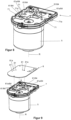
- a drive unit 4 according to the invention is attached to the transmission 31, which Figure 2 is shown separately in disassembled condition.
- the drive unit 4 has an electric motor 41.
- the motor 41 has a stator housing 5 in which a rotor shaft 42 is rotatably mounted about a rotor axis R.
- the rotor axis R defines the axial direction of the drive unit 4.
- a clutch 43 which in this example can be designed as a claw clutch, is attached to the rotor shaft 42 on the transmission side.
- Figure 3 shows the drive unit 4 in an exploded view in which the individual components are shown pulled apart in the axial direction of the rotor axis R.
- Phase windings 44 are mounted in the stator housing 5.
- a control housing 7 is mounted on the stator housing 5, which projects beyond the cross section of the stator housing 5 transversely to the rotor axis R, and has positioning receptacles designed as through openings 71, into which the positioning pins 61 can be inserted in the axial direction and receive them in a form-fitting manner.
- a control circuit board 8 is arranged, also referred to as a printed circuit board or PCB (printed circuit board), on which a control circuit with unspecified electronic components is constructed and interconnected.
- This board has positioning receptacles designed as through-openings 81, which are axially aligned with the positioning receptacles 71 of the connecting unit 7.
- the positioning pins 61 are designed such that, in the assembled state, they protrude axially through the through-openings 71 from the control housing 7 and can be inserted axially into the through-openings 81 of the control circuit board 8 for assembly.
- control board 8 By attaching a cover 9, the control board 8 is tightly enclosed in the control housing 7. Between the cover 9 and the control board 8, a connector housing 91 is mounted, into which an electrical connector (not shown) can be inserted for connection to the supply contacts of the control board 7.
- the connecting unit 6 has a common connecting body 62 formed as a plastic injection-molded part, from which the positioning pins 61 protrude axially.
- the positioning pins 61 have a first positioning section 63, which is formed by a plastic overmolding of electrically conductive contact pins made of a highly conductive metallic material.
- the contact pins 64 protruding axially from the first positioning section 63 form second positioning sections 64, which have a smaller cross-section than the first positioning sections 63.
- the positioning pins 61 are thus stepped in the axial direction.
- the connecting body 62 has axially continuous fastening openings 65 which correspond to axially projecting, pin-shaped fastening projections 45 - so-called bobbins - on the stator housing 5.
- the connecting unit 6 is moved axially in the direction of the arrow against the stator housing 5 until the fastening projections 45 engage positively in the fastening openings 65 and are fixed there by caulking, riveting, gluing or the like so that the connecting unit as shown in Figure 5 shown is fixed.
- control housing 7 is positioned relative to the stator housing 5 so that the through openings 71 are axially aligned with the positioning pins 61.
- the positioning pins 61 protrude axially further than the others; the positioning pins 61a have a length or height L2 which is longer than the length L1 of the positioning pins 61. If the control housing 7 is now moved axially against the stator housing 5 for assembly, the positioning pins 61a first enter the associated through-openings 71a, thereby ensuring relative orientation and alignment of the control housing 7, ensuring that the remaining positioning pins 61 are inserted into the associated through-openings 71.
- the through-openings 71, 71a of the control housing 7 can have different diameters to simplify positioning and insertion of the positioning pins 61, 61a.
- control housing 7 In the assembly state shown, the control housing 7 is positioned relative to the connecting unit 6 and thus also to the stator housing 5 in that the positioning pins 61, 61a with their first positioning sections 63 (see Figure 7 ) penetrate the through-openings 71, 71a in a form-fitting manner.
- the second positioning sections 64 of the positioning pins 61, 61a protrude axially from the control housing 7.
- control board 8 is positioned axially relative to the control housing 7 so that the through openings 81 are axially aligned with the positioning pins 61, namely with the positioning sections 64 projecting axially from the control housing 7.
- the control board 8 is then moved in the axial direction towards the control housing 7 until first the axially further projecting positioning pins 61a are inserted through the corresponding through-openings 81a, and then the remaining positioning pins 61, until the Figure 10 shown assembly state is reached.
- the control board 8 is is now located in the control housing 7 and, like the latter, is aligned transversely to the axial direction using the same positioning pins 61. Because the inner diameter of the through-openings 81 is precisely matched to the diameter or cross-section of the second positioning sections 64, precise positioning can be achieved.
- one or more of the through-openings 81, 81a can be designed as elongated holes that have play in the transverse direction, which, however, does not impair the alignment of the control board 8 relative to the control housing 7.
- the through-openings 81, 81a of the control board 8 can have different diameters to simplify positioning and insertion of the positioning pins 61, 61a.
- control board 7 sits axially on the axial stepped surface formed between the first positioning sections 63 and the second positioning sections 64. This additionally enables precise axial positioning of the control board 8 relative to the control housing 7.
- the positioning pins 61, 61a therefore have a positioning effect simultaneously in and transverse to the axial direction.
- the protruding positioning sections 64 can be connected to the control board 8, for example, by soldering. In addition to mechanical positioning and fixation, this creates a conductive connection between the contact pins comprising the second positioning sections 64 and the control circuit mounted on the control board 8.
- control housing 7 is closed by axially attaching the cover 9 so that the control board 8 is enclosed therein, as in the final state of assembly in Figure 11 , which corresponds to the state of Figure 2
- the connector housing 91 can, for example, be clamped between the cover 9 and the control board 8.
- the connecting unit 6 is shown schematically exploded, with the second positioning sections 64, which are formed by metallic contact pins 64, preferably made of wire, shown separately from the injection-molded plastic connecting body.
- These connecting sections 66 can be conductively connected to the phase windings 44, for example by crimping, pressing, soldering and/or welding or the like to the ends of the winding wire of these phase windings 44.
- FIGS. 13 , 14 and 15 show a second embodiment of a drive unit 4 according to the invention, wherein the same reference numerals are used for identical parts.
- the view of Figure 13 corresponds to the view of Figure 8 , Figure 14 with Figure 9, and Figure 15 with Figure 4 together with Figure 9 .
- Figure 18 shows a schematic exploded view similar to Figure 12 .
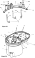
- the connecting unit 6 has a flat connecting body 62 which is annular with respect to the rotor axis R and which can also preferably be designed as a plastic injection-molded part.
- Contact pins 64 formed from wire sections - also referred to as second positioning pins - are firmly embedded in the connecting body 62, preferably by overmolding with the plastic in the injection molding process.
- the end sections of the contact pins 64 formed by the contact pins 64 and projecting parallel to the rotor axis R form positioning pins 61.
- Figure 17 It is clearly visible that all positioning pins 61 protrude axially from the connecting body 62 by the same distance.
- the positioning pins 61 are guided through positioning sections 63 which are formed integrally with the connecting body 62 and project axially therefrom in the direction of the rotor axis R,
- Two star-point connectors 67 which may be formed, for example, as sheet metal parts, are preferably permanently attached to the connecting body 62, for example by welding.
- the star-point connectors 67 are made of a highly conductive material, for example, copper, and each have at least three contact tabs 68, which can be conductively connected to the star-point ends of the winding wires of the three phase windings 44 at the star point.
- the contact tabs 68 can also be angled on the star-point connector, as shown, and protrude in the direction of the rotor axis R.
- the connecting unit 6 is inserted axially in the direction of the rotor axis R into the stator housing 5, as shown in Figure 15 indicated by the arrow.
- the rotor shaft 42 passes centrally through the opening of the annular connecting body 62.
- control housing 7 can already be attached to the stator housing 5 when assembling the connecting unit 6. Otherwise, the assembly is carried out as described above. Figures 4 and 5 How this is done in detail is explained above in connection with Figure 3 explained.
- connection unit 6 When the connection unit 6 is inserted as shown in Figure 14 As shown, the stator windings 44 are connected to the connecting sections 66 of the contact pins 64 and the contact tabs 68 of the star point connectors 67.
- control board 8 is then inserted into the stator housing 5 in the axial direction defined by the rotor axis R, as shown in Figure 14 indicated by the arrow.
- the positioning pins 61 and the positioning sections 63 engage with the through-holes 81 in the control board 8, thereby fixing the latter in position.
- Figure 18 shows a schematic exploded view of the connecting unit 6.
- the contact pins 64 formed by wire sections are embedded in the connecting body 62 designed as a plastic injection-molded part, as described above for the first embodiment in Figure 12 as already described.
- the star point connectors 67 can also be molded on or injected, or retrofitted.
Landscapes
- Engineering & Computer Science (AREA)
- Chemical & Material Sciences (AREA)
- Combustion & Propulsion (AREA)
- Transportation (AREA)
- Mechanical Engineering (AREA)
- Microelectronics & Electronic Packaging (AREA)
- Motor Or Generator Frames (AREA)
- Power Steering Mechanism (AREA)
Description
- Die Erfindung betrifft eine Antriebseinheit für eine elektrische Hilfskraftlenkung eines Kraftfahrzeugs, umfassend einen Elektromotor mit einem Statorgehäuse, an dem ein Steuerungsgehäuse angebracht ist, in dem eine Steuerplatine angeordnet ist, und mit einer an dem Statorgehäuse angebrachten Verbindungseinheit, die elektrische Verbindungselemente und mindestens ein Positionierelement aufweist, wobei die Verbindungselemente an den Elektromotor und an die Steuerplatine elektrisch angeschlossen sind und das Positionierelement zur relativen Positionierung mit der Steuerplatine zusammenwirkt, wobei das Positionierelement zur relativen Positionierung mit dem Steuerungsgehäuse zusammenwirkt.
- Im Stand der Technik sind Kraftfahrzeuglenkungen mit Hilfskraftunterstützung bekannt, bei denen zusätzlich zum Lenkmoment, welches vom Fahrer manuell auf das Lenkrad ausgeübt wird, durch eine elektro-mechanische Hilfskraftunterstützung zur Unterstützung und Entlastung des Fahrers eine Hilfskraft in den Lenkstrang eingebracht wird, und gegebenenfalls auch ein Zusatzlenkwinkel.
- Die Hilfskraft wird mittels eines elektrischen Hilfskraftantriebs erzeugt, der eine Antriebseinheit mit einem elektrischen Motor aufweist, dessen Rotorwelle über ein Hilfskraftgetriebe mit dem Lenkstrang gekoppelt ist.
- Eine gattungsgemäße Antriebseinheit ist im Stand der Technik beispielsweise aus der
DE 10 2018 216 744 A1 bekannt. Diese umfasst einen Motor mit einem Statorgehäuse, in dem die Stator- oder Phasenwicklungen angebracht sind, und in dem der Rotor mit der in Achsrichtung liegenden Rotorwelle drehbar gelagert ist. Die elektrische Ansteuerung des Motors erfolgt durch eine elektrische Steuerschaltung, die auf einer Steuerplatine, auch als Leiterplatte oder PCB (printed circuit board) bezeichnet, angeordnete und verschaltete elektrische Bauelemente aufweist. Diese Steuerplatine ist in einem Steuergehäuse, auch als Steuerungs- oder Steuerplatinengehäuse bezeichnet, angeordnet, welches mit dem Statorgehäuse zu einer kompakten Baugruppe verbunden ist, die auch als Powerpack bezeichnet wird. Die elektrische und mechanische Verbindung zwischen den Phasenwicklungen des Motors und der Steuerplatine erfolgt über eine Verbindungseinheit. Diese ist einerseits an dem Statorgehäuse fixiert und an die Phasenwicklungen des Motors angeschlossen, und andererseits mit dem Steuergehäuse verbunden und an die Steuerplatine angeschlossen. - Bei der bekannten Antriebseinheit weist die Verbindungseinheit Positionierelemente in Form von Positionierstiften auf, die in korrespondierende Aufnahmeöffnungen in der Steuerplatine formschlüssig eingreifen. Dadurch wirken die Positionierelemente mit der Steuerplatine derart zusammen, so dass eine Positionierung und Ausrichtung der Steuerplatine relativ zur Verbindungseinheit, und damit zum Statorgehäuse erzeugt wird. Die Steuerplatine ist im montierten Zustand in dem Steuergehäuse geschützt untergebracht. Nachteilig ist dabei jedoch, dass das Steuergehäuse nicht oder nur unzureichend relativ zur Steuerplatine ausgerichtet ist. Das Steuergehäuse ist nämlich seinerseits an dem Statorgehäuse oder der Verbindungseinheit befestigt. Dadurch, dass sich bezüglich der Ausrichtung der Steuerplatine relativ zum Steuergehäuse die Toleranzen der Verbindungen zwischen Statorgehäuse, Verbindungseinheit und Steuerplatine addieren, kann die Montage der Steuerplatine erschwert werden, und es besteht ein erhöhtes Risiko von Beschädigungen bei der Montage.
- Eine Antriebseinheit der eingangs genannten Art ist im Stand der Technik beispielsweise aus
JP 2013 106376 A JP 2018 125948 A US 2015/222156 A1 ,US 2014/125173 A1 oderEP 1 955 927 A1 bekannt. Nachteilig an sämtlichen darin beschriebenen Ausführungen ist, dass die Montage umständlich ist. - Angesichts der vorangehend erläuterten Problematik ist es eine Aufgabe der vorliegenden Erfindung, eine einfachere und sicherere Montage einer Antriebseinheit zu ermöglichen.
- Diese Aufgabe wird erfindungsgemäß gelöst durch die Antriebseinheit mit den Merkmalen des Anspruchs 1. Vorteilhafte Weiterbildungen ergeben sich aus den Unteransprüchen.
- Bei einer Antriebseinheit für eine elektrische Hilfskraftlenkung eines Kraftfahrzeugs, umfassend einen Elektromotor mit einem Statorgehäuse, an dem ein Steuerungsgehäuse angebracht ist, in dem eine Steuerplatine angeordnet ist, und mit einer an dem Statorgehäuse angebrachten Verbindungseinheit, die elektrische Verbindungselemente und mindestens ein Positionierelement aufweist, wobei die Verbindungselemente an den Elektromotor und an die Steuerplatine elektrisch angeschlossen sind und das Positionierelement zur relativen Positionierung mit der Steuerplatine zusammenwirkt, wobei das Positionierelement zur relativen Positionierung mit dem Steuerungsgehäuse zusammenwirkt, ist erfindungsgemäß vorgesehen, dass mindestens ein Positionierelement relativ zu einem anderen Positionierelement von dem Statorgehäuse weiter vorsteht.
- Gemäß der Erfindung ist somit das mindestens eine Positionierelement, welches weiter vorsteht, länger als das oder die übrigen Positionierelemente, oder als das oder die Verbindungselemente. Das längere Positionierelement ist vorzugsweise mindestens 1mm länger oder mindestens 2mm länger als das andere Positionier-oder Verbindungselement. Dadurch, dass ein bevorzugt als Positionierstift ausgebildetes Positionierelement axial, in Achsrichtung weiter vorsteht, kann es in eine korrespondierende Positionieraufnahme, bevorzugt eine Aufnahmeöffnung, axial eingesetzt werden, wobei noch eine relative Orientierung des oder der übrigen, axial bezüglich der Montagerichtung weiter zurückliegenden Positionierelemente, die noch nicht in die korrespondierenden Positionieraufnahmen eingreifen, ermöglicht werden. Sobald ein, oder auch zwei vorstehende Positionierelemente formschlüssig in der definierten Einbaulage eingesetzt sind, sind die übrigen Positionierelemente automatisch bezüglich der korrespondierenden Positionieraufnahmen ausgerichtet und können durch weitere axiale Bewegung montiert werden. Dadurch kann die Montage vereinfacht werden.
- Besonders bevorzugt ist der Elektromotor in dem Statorgehäuse angeordnet, welcher einen Stator mit Stator- oder Phasenwicklungen umfasst, in dem ein Rotor mit einer in Achsrichtung liegenden Rotorwelle drehbar gelagert ist.
- Die Verbindungseinheit ist an dem Statorgehäuse positioniert und fixiert, und stellt mindestens ein erfindungsgemäßes Positionierelement, bevorzugt mehrere Positionierelemente bereit. Erfindungsgemäß ist das Positionierelement eingerichtet und ausgestaltet, um die positionsgenaue Ausrichtung sowohl der Steuerplatine als auch des Steuergehäuses relativ zur Verbindungseinheit zu ermöglichen. Mit anderen Worten sind die Steuerplatine und das Steuerungsgehäuse jeweils direkt an dem Positionierelement ausgerichtet, und damit parallel zueinander an demselben Positionierelement relativ zu der Verbindungseinheit positioniert und ausgerichtet, und nicht wie im Stand der Technik über eine serielle Anordnung von Verbindungen. Somit wird die im Stand der Technik unvermeidliche und potentiell schädliche Addition der Toleranzen der seriell angeordneten Verbindungen vermieden, und es wird eine verbesserte und präzisere Positionierung der Steuerplatine und des Steuergehäuses sichergestellt. Durch die verbesserte Maßhaltigkeit der Anordnung wird die Montage, insbesondere in der automatisierten Fertigung, vereinfacht. Die relative Orientierung zwischen dem Steuerungsgehäuse und dem Positionierelement ist weitestgehend unabhängig von Toleranzen, so dass durch die erfindungsgemäße Ausrichtung der Steuerplatine an diesem Positionierelement eine entsprechend genaue Ausrichtung der Steuerplatine relativ zum Steuerungsgehäuse gewährleistet ist. Durch diese reproduzierbare, toleranzarme Ausrichtung wird die Montage vereinfacht, und die Gefahr von Beschädigungen durch relative Fehlorientierungen beim Einsetzen der Steuerplatine in das Steuerungsgehäuse und beim Zusammenfügen der Verbindungen zwischen der Verbindungseinheit und der Steuerplatine verringert.
- Die vorteilhaften Auswirkungen kommen insbesondere dadurch zustande, dass das oder die erfindungsgemäßen Positionierelemente erstmals eine gemeinsame Referenzposition zur Ausrichtung und Orientierung von Steuerungsgehäuse und Steuerplatine zur Verfügung stellen, wodurch toleranzbedingte Probleme und das Risiko von Beschädigungen bei der Montage verringert und weitgehend vermieden werden können.
- Das Steuerungsgehäuse kann am Statorgehäuse fixiert sein, beispielsweise angeflanscht sein, beispielsweise mittels Befestigungsbolzen, die durch korrespondierende Befestigungsbohrungen hindurchgeführt und verschraubt sind. Durch ein hinreichend groß vorgegebenes Spiel kann die Fixierung in der durch die Positionierelemente definierten relativen Positionierung erfolgen. Das Steuerungsgehäuse kann beispielsweise stirnseitig bezüglich einer Achsrichtung, die durch die Rotorachse definiert ist, bevorzugt außen an dem Statorgehäuse festgelegt sein, beispielsweise durch eine Flanschverbindung. Alternativ oder zusätzlich können lösbare und/oder unlösbare Verbindungsmittel vorgesehen sein, zur Fixierung in der durch das oder die erfindungsgemäßen Positionierelemente vorgegebenen relativen Positionierung des Steuerungsgehäuses zur Verbindungseinheit und zum Statorgehäuse.
- Die Ausrichtung und Fixierung der Steuerplatine kann an dem oder den erfindungsgemäßen Positionierelementen erfolgen, wenn das Steuerungsgehäuse relativ zu den Positionierelementen positioniert und fixiert ist. Dabei kann die Steuerungsplatine lösbar oder unlösbar mit mindestens einem Positionierelement verbunden sein, oder alternativ oder zusätzlich an dem Steuerungsgehäuse.
- Die gleichzeitige Positionierung und Fixierung der Steuerplatine an einem Positionierelement hat den Vorteil einer rationellen Montage. Das oder die Positionierelemente können gleichzeitig als Befestigungselemente oder Verbindungelemente zwischen der Verbindungseinheit und der Steuerplatine und/oder dem Steuerungsgehäuse dienen. Die Fixierung kann lösbar oder unlösbar erfolgen, beispielsweise durch Löten, Kleben, Pressen, Verschrauben, Verklemmen oder dergleichen erfolgen. Dabei ist es denkbar und möglich, die Verbindung elektrisch leitfähig auszugestalten, und durch ein elektrisch leitfähiges Positionierelement eine elektrische Verbindung zwischen Verbindungseinheit und Steuerplatine zu erzeugen.
- Dadurch kann der Fertigungs- und Montageaufwand reduziert werden. Somit sind die einen Positionierelemente als Phasenstecker des Elektromotors ausgebildet, während die anderen Positionierelemente der Positionierung dienen.
- Das Steuerungsgehäuse kann nach außen über den Querschnitt des Statorgehäuses überstehen, beispielsweise seitlich quer zur Achsrichtung der Rotorachse. Dadurch ist es möglich, eine Steuerungsplatine einzusetzen, die größer ist als der im Innenquerschnitt des Statorgehäuses zur Verfügung stehende Einbauraum. Dies ermöglicht weiterhin eine verbesserte Kühlung der auf der Steuerplatine angebrachten elektronischen Komponenten. Dies sind weitere Vorteile gegenüber dem Stand der Technik, bei dem die Steuerplatine zusammen mit dem Steuerungsgehäuse innerhalb des Statorgehäuses angeordnet ist, wodurch der Einbauraum und die Möglichkeiten der Wärmeabfuhr eingeschränkt sein können.
- Es kann vorgesehen sein, dass mindestens ein Positionierelement formschlüssig in eine korrespondierende Positionieraufnahme in dem Steuergehäuse eingreift. Die Positionieraufnahme kann dazu beispielsweise eine Ausnehmung oder eine bevorzugt in Achsrichtung durchgehende Durchgangsöffnung aufweisen, in welche das Positionierelement in einer Montagerichtung eingesetzt werden kann, zur Ausbildung eines Formschlusses. Die Montagerichtung kann bevorzugt der Achsrichtung entsprechen, und der Formschluss kann in dieser Richtung und/oder quer dazu wirksam sein. Das oder die Positionierelemente können ebenfalls in korrespondierende Positionieraufnahmen in der Steuerplatine eingreifen, beispielsweise formschlüssig in Ausnehmungen oder Durchgangsöffnungen.
- Eine mit geringem Aufwand realisierbare und effektive Ausführung ist, dass mindestens ein Positionierelement einen in einer Achsrichtung des Motors ausgerichteten Positionierstift aufweist. Die Verbindungseinheit kann bevorzugt an dem Statorgehäuse derart angebracht sein, dass ein oder mehrere Positionierstifte stirnseitig axial vorstehen. Die damit korrespondierenden Positionieraufnahmen in dem Steuerungsgehäuse und der Steuerplatine können einfach als Öffnungen oder Ausnehmungen ausgebildet sein, in denen der Positionierstift einfach durch axiales Einstecken aufnehmbar ist. Bevorzugt kann eine axial durchgehende Durchgangsöffnung vorgesehen sein, beispielsweise in dem Steuerungsgehäuse, durch welche ein Positionierstift in Achsrichtung hindurch steckbar ist. Auf einem axial aus der Durchgangsöffnung des Steuerungsgehäuses vorstehenden Abschnitt eines Positionierstifts, einem Positionierabschnitt, kann die Steuerplatine mit einer korrespondierenden Positionieraufnahme, ebenfalls einer Ausnehmung oder Öffnung, positioniert und gegebenenfalls fixert werden. Eine derartige Anordnung von Positionierstiften und korrespondierenden Positionieraufnahmen ist mit geringem Aufwand darstellbar und ermöglich eine einfache und sichere Montage. Bei der Montage kann zuerst das Steuerungsgehäuse auf den oder die Positionierstifte aufgesteckt werden, und anschließend die Steuerplatine.
- Ein Positionierstift kann einen kreisrunden, oder einen unrunden, wie beispielsweise einen mehreckigen oder anders geformten Querschnitt haben, der mit einem Innenquerschnitt einer Aufnahmeöffnung einer Positionieraufnahme korrespondiert. Dadurch kann ein einfaches Einsetzen in Achsrichtung ermöglicht werden, was einer axialen Montagerichtung entspricht. Durch eine entsprechende Anpassung von Form und Abmessungen kann ein Formschluss quer zur Montagerichtung erzeugt werden. Gegebenenfalls kann auch ein definiertes Spiel vorgesehen sein, beispielsweise durch Ausbildung eines Langloches oder Schlitzes, wodurch Toleranzen in einer Richtung ausgeglichen werden können, welche sich nicht negativ auf die erfindungsgemäße relative Ausrichtung von Steuerungsgehäuse und Steuerplatine auswirkt.
- Es kann vorgesehen sein, dass mindestens ein Positionierelement mindestens einen ersten Positionierabschnitt zum Eingriff in das Steuerungsgehäuse und mindestens einen zweiten Positionierabschnitt zum Eingriff in die Steuerplatine aufweist. Der erste Positionierabschnitt kann beispielsweise einen größeren Querschnitt haben als der zweite Positionierabschnitt, beispielsweise bei einem Positionierstift einen größeren Durchmesser. Es kann beispielsweise ein in Achsrichtung gestufter Positionierstift ausgebildet sein. Das Steuerungsgehäuse kann mit einer als Durchgangsöffnung ausgebildeten Positionieraufnahme in axialer Montagerichtung über den zweiten Positionierabschnitt hinweg formschlüssig auf den ersten Positionierabschnitt aufgesteckt werden. Im fertigen Montagezustand, wenn das Steuerungsgehäuse auf dem ersten Positionierabschnitt sitzt und fixiert ist, steht der zweite Montageabschnitt axial aus dem Steuerungsgehäuse vor. Auf diesem vorstehenden zweiten Positionierabschnitt kann nun in axialer Montagerichtung die Steuerplatine aufgesteckt werden, bis der zweite Positionierabschnitt formschlüssig in der korrespondierenden Positionieraufnahme der Steuerplatine sitzt. Dadurch kann die Steuerplatine relativ zum Positionierelement und damit gleichzeitig relativ zum Steuerungsgehäuse ausgerichtet werden.
- Die Positionieraufnahmen des Steuerungsgehäuses und der Steuerplatine können für ein vereinfachtes Positionieren und Hindurchstecken des mindestens einen längeren und axial weiter hervorstehenden Positionierelements im Vergleich zu den übrigen Positionieraufnahmen unterschiedliche Durchmesser aufweisen.
- Es ist möglich, dass mindestens ein Positionierelement ein Verbindungselement aufweist. Dadurch kann ein Verbindungselement mit einem Positionierelement integriert ausgebildet sein. Beispielsweise kann ein Verbindungs- oder Kontaktelement einen Positionierstift mit einem integrierten elektrischen Leiter aufweisen, beispielsweise aus einem metallischen Werkstoff. Das Kontaktelement kann beispielsweise als Kontaktstift aus einem Draht ausgebildet sein.
- Es ist möglich, dass ein Verbindungselement zumindest abschnittweise eine Umhüllung aus nichtleitendem Material aufweist. Ein oder mehrere Verbindungselemente können beispielsweise jeweils einen Kontaktstift aufweisen, der zusätzlich auch einen Positionierabschnitt eines Positionierelements aufweisen kann oder als solcher dient. Ein oder mehrere derartige Verbindungselemente oder Kontaktstifte können beispielsweise durch eine Kunststoff-Umspritzung aus einem thermoplastischen, elektrisch isolierenden Kunststoff umhüllt sein. Auf diese Weise kann die Umhüllung ein oder mehrere isolierte Abschnitte aufweisen, die auch als Positionierabschnitte eins erfindungsgemäßen Positionierelements ausgebildet sein können.
- Die Kontaktstifte können als vorzugsweise gebogene Drahtabschnitte bereitgestellt werden, welche axial in Richtung der Rotorachse aus dem Kunststoff vorstehende Positionierabschnitte aufweisen. An den bezüglich der Positionieranschnitten abgewandten Endbereichen können jeweils Verbindungsabschnitte vorgesehen sein zur leitenden Verbindung mit den Drahtenden der Phasenwicklungen. Die Verbindungsabschnitte können abgewinkelt sein, um den Prozess zur Montage und der Erzeugung einer leitenden Verbindung zu vereinfachen, beispielsweise durch Crimpen oder Verschweißen.
- Zum Einbetten in den Verbbindungskörper können die fertig gebogenen Kontaktstifte in die Spritzgussform eingelegt und anschließend mit schmelzflüssigem Kunststoff umspritzt werden. Die Positionierabschnitte stehen dann als blanke Drahtabschnitte aus dem Kunststoff vor.
- Eine vorteilhafte Weiterbildung kann vorsehen, dass eine Mehrzahl von Positionierelementen einstückig miteinander verbunden ausgebildet sind, bevorzugt als Kunststoff-Spritzgussteil. Dadurch kann fertigungstechnisch günstig und mit geringen Maßtoleranzen eine Verbindungseinheit einschließlich der Positionierelemente als Spritzgussteil, bevorzugt aus thermoplastischem Kunststoff, zur Verfügung gestellt werden. Eine vorteilhafte Weiterbildung kann vorsehen, dass ein oder mehrere Verbindungselemente, beispielsweise metallische Kontaktstifte, in das Kunststoff-Spritzgussteil der Verbindungseinheit eingebettet sind. Besonders vorteilhaft kann es dabei sein, ein Verbindungs- oder Kontaktelement in einem Positionierelement einzubetten. Durch diese Integration wird eine vorteilhafte Mehrfach-Funktionalität ermöglicht: Beispielsweise kann im Kunststoff-Spritzguss mit geringem Aufwand und hoher Genauigkeit ein gestufter Positionierstift wie oben beschrieben bereitgestellt werden, und es können mehrere derartige Positionierstifte mit einer Verbindungseinheit einstückig integriert werden.
- Zur Montage der Verbindungseinheit an dem Statorgehäuse kann bevorzugt vorgesehen sein, dass korrespondierende Befestigungselemente vorgesehen sind, die lösbar oder unlösbar miteinander fixiert werden. Vorzugsweise sind die Befestigungselemente eingerichtet und ausgestaltet, so dass sie in einer axialen Montagerichtung zusammengefügt werden können, um anschließend fixiert zu werden. Beispielsweise können die Befestigungselemente Zapfen - sogenannte Bobbins - und korrespondierende Aufnahmeöffnungen aufweisen, welche formschlüssig zusammengefügt werden können. Eine unlösbare Verbindung kann mittels Schweißen, Kleben, Verstemmen, Nieten oder dergleichen rationell, sicher und maßgenau erfolgen.
- Eine vorteilhafte Weiterbildung kann vorsehen, dass das Steuerungsgehäuse auf seiner dem Statorgehäuse abgewandten Seite mit einem Steuergehäusedeckel verschlossen ist, so dass die Elektronikbauteile der Steuerplatine und andere empfindliche Elemente des Motors gegen Schmutz und Feuchtigkeit geschützt sind.
- Zur Montage einer erfindungsgemäßen Antriebseinheit wird zunächst ein Statorgehäuse bereitgestellt, in dem der Rotor des Elektromotors bereits betriebsbereit drehbar gelagert sein kann. An dem Statorgehäuse kann bevorzugt, wie oben beschrieben, stirnseitig in axialer Montagerichtung eine Verbindungseinheit fixiert werden. Beispielsweise können korrespondierende Befestigungselemente der Verbindungseinheit und des Statorgehäuses bevorzugt formschlüssig in axialer Montagerichtung zusammengesetzt und miteinander fixiert werden. Dadurch ist die Verbindungseinheit derart in Position relativ zum Statorgehäuse fixiert, dass das oder die erfindungsgemäßen Positionierelemente zur nachfolgenden Montage des Steuerungsgehäuses positioniert und ausgerichtet sind. Bevorzugt können die Positionierelemente mindestens einen stirnseitig axial vorstehenden Positionierstift aufweisen, vorzugsweise mehrere stiftförmige, langgestreckte Positionierstifte.
- Anschließend erfolgt das Ausrichten des Steuerungsgehäuses an mindestens einem Positionierelement der Verbindungseinheit und Fixieren relativ zum Statorgehäuse. Beim Ausrichten werden eine oder mehrere Befestigungsaufnahmen, bevorzugt Durchgangsöffnungen, axial fluchtend vor den korrespondierenden Positionierelementen, bevorzugt Positionierstiften angeordnet. Durch eine axiale Montagebewegung wird das Steuerungsgehäuse auf die Verbindungseinheit in Achsrichtung aufgesteckt, bis die Positionierstifte in die korrespondierenden Positionieröffnungen bevorzugt formschlüssig eintauchen, und dabei bevorzugt auf korrespondierenden ersten Positionierabschnitten sitzen. Bevorzugt ragen dabei die Positionierelemente dabei mit zweiten Positionierabschnitten axial über das Steuerungsgehäuse vor. Dank der Erfindung sind diese zweiten Positionierabschnitte allein durch das einfache Aufstecken präzise relativ zum Steuerungsgehäuse positioniert.
- Anschließend erfolgt das Ausrichten der Steuerplatine an dem Positionierelement und Fixieren relativ zu dem Statorgehäuse. Zum Ausrichten wird eine korrespondierende Positionieraufnahme, beispielsweise eine axiale Positionieröffnung in der Steuerplatine, axial fluchtend vor dem bevorzugt als Positionierstift ausgebildeten Positionierelement angeordnet. Anschließend wird die Steuerplatine in axialer Montagerichtung auf das Steuerungsgehäuse zu bewegt, bis es in dieses eingesetzt ist und besagte zweite Positionierabschnitte des oder der Positionierstifte formschlüssig in die korrespondierenden Positionieröffnungen der Steuerplatine eintauchen. Dadurch wird die Steuerplatine selbständig auf dem oder den Positionierelementen ausgerichtet, und damit gleichzeitig relativ zu dem Steuerungsgehäuse.
- Danach kann die Fixierung der Steuerplatine lösbar oder unlösbar erfolgen, beispielsweise durch Löten, Kleben, Pressen, Verschrauben, Verklemmen oder dergleichen. Dabei ist es denkbar und möglich, die Verbindung elektrisch leitfähig auszugestalten. Bevorzugt kann die Steuerplatine an dem oder den Positionierelementen festgelegt werden. Durch die Fixierung der Steuerplatine kann gleichzeitig auch das bezüglich der Montagerichtung unterhalb der Steuerplatine angeordnete Steuerungsgehäuse an der Verbindungseinheit fixiert werden.
- Die Verbindungseinheit ist bevorzugt über elektrische Verbindungelemente an die Statorwicklungen angeschlossen, und mittels Verbindungselementen an die Steuerplatine angeschlossen. Die Verbindungselemente können in die Positionierelemente integriert sein, und beispielsweise einen leitfähigen Stift aufweisen, der bevorzugt über eine elektrisch leitfähige Verbindung wie Löten oder dergleichen mit der Steuerplatine mechanisch und elektrisch verbunden ist.
- Ein Vorteil des erfindungsgemäßen Verfahrens ist, dass bei der Montage des Steuerungsgehäuses das oder die Positionierelemente selbsttätig ausgerichtet sind, und die nachfolgende Montage der Steuerplatine auf diesem oder diesen Positionierelementen einfach und präzise erfolgen kann. Dadurch wird das Risiko von Beschädigungen bei der Montage verringert, insbesondere auch bei automatisierten Montageverfahren.
- Bevorzugt kann die Verbindungseinheit an dem einen oder mehreren Befestigungselementen unlösbar befestigt werden, die relativ zum Statorgehäuse und/oder zur Verbindungseinheit in einer Achsrichtung des Statorgehäuses vorstehen. Die Achsrichtung ist durch die Rotorachse vorgegeben. Die Befestigungselemente können beispielsweise einen oder mehrere axial stirnseitig vorstehende Befestigungsstifte oder -vorsprünge oder sogenannte Bobbins umfassen, auf die die Verbindungseinheit mit korrespondierenden Befestigungsöffnungen axial aufgesteckt und fixiert wird, beispielsweise durch Vernieten, Pressen oder dergleichen. Durch formschlüssig zusammenwirkende Befestigungselemente kann eine genaue Ausrichtung der Verbindungseinheit relativ zum Statorgehäuse erfolgen.
- Bevorzugt können die Positionierelemente mindestens einen in einer Achsrichtung erstreckten Positionierstift aufweisen, auf die das Steuerungsgehäuse und die Steuerplatine mit korrespondierenden Positionieraufnahmen in Achsrichtung aufgesteckt wird. Das axiale Aufstecken ermöglicht eine besonders einfache Montage. Als Positionieraufnahme können mit geringem Aufwand Aufnahmeöffnungen in der Steuerplatine und/oder dem Steuerungsgehäuse ausgebildet werden.
- Bei der Montage kann vorgesehen sein, dass das Steuerungsgehäuse an einem ersten Positionierabschnitt des Positionierelements positioniert wird, und die Steuerplatine an einem zweiten Positionierabschnitt positioniert wird. Die Positionierung quer zur Montagerichtung kann einfach durch einen formschlüssigen Eingriff des jeweiligen Positionierabschnitts in eine korrespondierende Positionieraufnahme bzw. -öffnung erfolgen. Beispielsweise kann ein Positionierstift gestuft sein, und axial aufeinander folgende Positionierabschnitte mit unterschiedlichem Durchmesser und/oder Querschnitt haben. Dann kann zur Montage erst das Steuerungsgehäuse auf den ersten Positionierabschnitt axial aufgesteckt werden, und dann die Steuerplatine.
- Die Steuerplatine kann an mindestens einem der Positionierelemente fixiert sein, beispielsweise durch eine unlösbare oder lösbare Verbindung. Dadurch kann gleichzeitig das Steuerungsgehäuse an dem Positionierstift fixiert sein.
- Bevorzugt kann bei der Montage vorgesehen sein, dass elektrische Verbindungselemente der Verbindungseinheit mit korrespondierenden Anschlusselementen an dem Stator und der Steuerplatine elektrisch verbunden werden. Die elektrische Verbindung kann zusammen bzw. gleichzeitig mit der mechanischen Verbindung erzeugt werden, beispielsweise durch Löten, Quetschen oder dergleichen, oder auch durch lösbare Steckverbinder oder dergleichen.
- Nach der Montage des Steuerungsgehäuses an dem Statorgehäuse und der Anbringung der Steuerplatine in dem Steuerungsgehäuse kann dieses durch Anbringung einer Abdeckung oder eines Steuergehäusedeckels geschlossen werden, so dass die Steuerplatine bevorzugt abgedichtet eingeschlossen ist.
- An dem Verbindungskörper kann mindestens ein Sternpunktverbinder angebracht sein. Ein Sternpunktverbinder ist aus gut leitfähigem Material ausgebildet, beispielsweise aus Kupfer, und weist jeweils mindestens drei Kontaktelemente wie Kontaktlaschen oder -fahnen auf, die mit den sternpunktseitigen Enden der Wicklungsdrähte der drei Phasenwicklungen im Sternpunkt leitend verbindbar sind. Ein Sternpunktverbinder kann beispielsweise als Blech- oder Drahtformteil ausgebildet sein, und bevorzugt an dem Verbindungskörper der Verbindungseinheit vorzugsweise unlösbar angebracht sein, beispielsweise durch Verschweißen. Die Kontaktelemente können ebenfalls wie dargestellt an dem Sternpunktverbinder abgewinkelt sein und in Richtung der Rotorachse von der Verbindungseinheit vorstehen. Ein Vorteil ist, dass der Sternpunkt mit geringem Aufwand mit der Verbindungseinheit integriert sein kann, wodurch die Montage erleichtert und Bauraum eingespart werden kann.
- Vorteilhafte Ausführungsformen der Erfindung werden im Folgenden anhand der Zeichnungen näher erläutert. Im Einzelnen zeigen:
- Figur 1
- eine Hilfskraftlenkung für ein Kraftfahrzeug in einer schematischen perspektivischen Darstellung,
- Figur 2
- eine Antriebseinheit einer Hilfskraftlenkung gemäß
Figur 1 , - Figur 3
- die Antriebseinheit gemäß
Figur 2 in einer schematischen, in Achsrichtung auseinander gezogenen Darstellung, - Figur 4
- eine schematische Darstellung der Antriebseinheit gemäß
Figur 2 oder3 in einem ersten Montagezustand des erfindungsgemäßen Verfahrens, - Figur 5
- eine schematische Darstellung in einem zweiten, auf
Figur 4 folgenden Montagezustand, - Figur 6
- eine schematische Darstellung in einem dritten, auf
Figur 5 folgenden Montagezustand, - Figur 7
- eine seitliche Ansicht des in
Figur 5 gezeigten Montagezustands, - Figur 8
- eine schematische Darstellung in einem vierten, auf
Figur 6 folgenden Montagezustand, - Figur 9
- eine schematische Darstellung in einem fünften, auf
Figur 8 folgenden Montagezustand, - Figur 10
- eine schematische Darstellung in einem sechsten, auf
Figur 9 folgenden Montagezustand, - Figur 11
- eine schematische Darstellung im fertig montierten Endzustand wie in
Figur 2 , - Figur 12
- eine Verbindungseinheit einer Antriebseinheit gemäß
Figuren 1 bis 11 in einer schematisch auseinander gezogenen Darstellung, - Figur 13
- eine schematische Darstellung der Antriebseinheit in einer zweiten Ausführungsform in einem ersten Montagezustand in einer Ansicht entsprechend Figur 8,
- Figur 14
- die Antriebseinheit gemäß
Figur 13 in einer Ansicht entsprechendFigur 5 , - Figur 15
- die Antriebseinheit gemäß
Figur 14 in einer Ansicht entsprechendFigur 4 , - Figur 16
- eine Verbindungseinheit einer Antriebseinheit gemäß
Figuren 13 bis 15 in einer schematischen perspektivischen Ansicht, - Figur 17
- die Verbindungseinheit gemäß
Figur 16 in einer weiteren schematischen perspektivischen Ansicht ähnlichFigur 4 , - Figur 18
- eine Verbindungseinheit einer Antriebseinheit gemäß
Figuren 13 bis 17 in einer schematisch auseinander gezogenen Darstellung. - In den verschiedenen Figuren sind gleiche Teile stets mit den gleichen Bezugszeichen versehen und werden daher in der Regel auch jeweils nur einmal benannt bzw. erwähnt.
-
Figur 1 zeigt eine Hilfskraftlenkung 1, die an einer Lenkwelle 2 angebracht ist, welche um ihre Längsachse L, die Lenkwellenachse, drehbar gelagert ist. Die Lenkwelle 2 weist eine Innenwelle 21 auf, die drehmomentschlüssig und in Längsrichtung teleskopartig verstellbar in einer Außenwelle 22 angeordnet ist. An ihrem bezüglich der Fahrtrichtung hinteren Ende weist die Lenkwelle 2 einen Befestigungsabschnitt 23 zur Anbringung eines nicht dargestellten Lenkrads auf. - Ein elektrischer Hilfskraftantrieb 3 weist ein Getriebe 31 auf, bevorzugt ein Schneckengetriebe, dessen Ausgangsrad drehfest mit der Lenkwelle 2 gekuppelt ist, nämlich mit der Innenwelle 21.
- Eingangsseitig ist an dem Getriebe 31 eine erfindungsgemäße Antriebseinheit 4 angebracht, die in
Figur 2 separat in demontiertem Zustand gezeigt ist. - Die Antriebseinheit 4 weist einen elektrischen Motor 41 auf. Der Motor 41 weist ein Statorgehäuse 5 auf, in dem eine Rotorwelle 42 um eine Rotorachse R drehbar gelagert ist. Die Rotorachse R definiert die Achsrichtung der Antriebseinheit 4. Zur drehmomentschlüssigen Verbindung mit dem Getriebe 31 ist an der Rotorwelle 42 getriebeseitig eine Kupplung 43, welche in diesem Beispiel als Klauenkupplung ausgebildet sein kann, angebracht.
-
Figur 3 zeigt die Antriebseinheit 4 in einer Explosionsdarstellung, in der die einzelnen Komponenten in Achsrichtung der Rotorachse R auseinandergezogen dargestellt sind. - In dem Statorgehäuse 5 sind Phasenwicklungen 44 angebracht.
- An dem Statorgehäuse 5 ist axial auf der dem Getriebe 31 abgewandten Seite eine Verbindungseinheit 6 angebracht, die als parallel axial vorstehende Positionierstifte 61 ausgebildete Positionierelemente aufweist.
- Auf den Statorgehäuse 5 ist ein Steuerungsgehäuse 7 angebracht, welches über den Querschnitt des Statorgehäuses 5 quer zur Rotorachse R übersteht, und als Durchgangsöffnungen 71 ausgebildete Positionieraufnahmen aufweist, in welche die Positionierstifte 61 in Achsrichtung einsteckbar sind, und diese formschlüssig aufnehmen.
- In einem dem Statorgehäuse 5 abgewandten Innenraum des Steuerungsgehäuses 7 ist eine Steuerplatine 8 angeordnet, auch als Leiterplatte oder PCB (printed circuit board) bezeichnet, auf der eine Steuerschaltung mit nicht näher bezeichneten elektronischen Bauelementen aufgebaut und verschaltet ist. Diese weist als Durchgangsöffnungen 81 ausgebildete Positioieraufnahmen auf, die mit den Positionieraufnahmen 71 der Verbindungseinheit 7 axial fluchten. Die Positionierstifte 61 sind ausgebildet, dass sie im montierten Zustand durch die Durchgangsöffnungen 71 hindurch aus dem Steuerungsgehäuse 7 axial vorstehen, und zur Montage axial in die Durchgangsöffnungen 81 der Steuerplatine 8 eingesteckt werden können.
- Durch Anbringung eines Deckels 9 wird die Steuerplatine 8, dicht in dem Steuerungsgehäuse 7 eingeschlossen. Zwischen dem Deckel 9 und der Steuerplatine 8 ist ein Steckergehäuse 91 angebracht, in den ein nicht dargestellter elektrischer Verbinder einsteckbar ist zum Anschluss an Versorgungskontakte der Steuerplatine 7.
- In den
Figuren 4 bis 10 ist die Herstellung einer Antriebseinheit 1 gemäß dem erfindungsgemäßen Verfahren in aufeinander folgenden Montagezuständen gezeigt. - In
Figur 4 ist erkennbar, dass die Verbindungseinheit 6 einen als Kunstsoff-Spritzgussteil ausgebildeten gemeinsamen Verbindungskörper 62 aufweist, von dem die Positionierstifte 61 axial abstehen. Die Positionierstifte 61 weisen einen ersten Positionierabschnitt 63 auf, der durch eine Kunststoff-Umspritzung von elektrisch leitenden Kontaktstiften gebildet wird, die aus einem gut leitfähigen metallischen Werkstoff bestehen. Die aus dem ersten Positionierabschnitt 63 axial vorstehenden Kontaktstifte 64 bilden zweite Positionierabschnitte 64, die einen kleineren Querschnitt haben als die ersten Positionierabschnitte 63. Die Positionierstifte 61 sind somit in axialer Richtung gestuft ausgebildet. - Der Verbindungskörper 62 weist axial durchgehende Befestigungsöffnungen 65 auf, die mit axial vorstehenden, stiftförmigen Befestigungsvorsprüngen 45 - sogenannten Bobbins - an dem Statorgehäuse 5 korrespondieren.
- Ausgehend von dem in
Figur 4 gezeigten Montagezustand wird die Verbindungseinheit 6 in Pfeilrichtung axial gegen das Statorgehäuse 5 bewegt, bis die Befestigungsvorsprünge 45 formschlüssig in die Befestigungsöffnungen 65 eintauchen, und dort durch Verstemmen, Vernieten, Verkleben oder dergleichen festgelegt werden so dass die Verbindungseinheit wie inFigur 5 gezeigt fixiert ist. - Im nächsten Schritt wird wie in
Figuren 6 und 7 gezeigt das Steuerungsgehäuse 7 relativ zu dem Statorgehäuse 5 positioniert, so dass die Durchgangsöffnungen 71 mit den Positionierstiften 61 axial fluchten. - In der Seitenansicht quer zur Achsrichtung in
Figur 7 ist gut erkennbar, dass im gezeigten Beispiel von den Positionierstiften 61 zwei Positionierstifte 61a axial weiter vorstehen als die Übrigen, die Positionierstifte 61a weisen eine Länge oder Höhe L2 auf, welche länger ist als die Länge L1 der Positionierstifte 61. Wird nun zur Montage das Steuerungsgehäuse 7 axial gegen das Statorgehäuse 5 bewegt, tauchen die Positionierstifte 61a zuerst in die zugehörigen Durchgangsöffnungen 71a ein, wodurch eine relative Orientierung und Ausrichtung des Steuerungsgehäuses 7 erfolgt, so dass das Einsetzen der übrigen Positionierstifte 61 in die zugehörigen Durchgangsöffnungen 71 gewährleistet ist. Die Durchgangsöffnungen 71, 71a des Steuerungsgehäuses 7 können für ein vereinfachtes Positionieren und Hindurchstecken der Positionierstifte 61,61a unterschiedliche Durchmesser aufweisen. - In dem in
Figur 8 gezeigten Montagezustand ist das Steuerungsgehäuse 7 dadurch relativ zur Verbindungseinheit 6 und damit auch zum Statorgehäuse 5 positioniert, dass die Positionierstifte 61, 61a mit ihren ersten Positionierabschnitten 63 (sieheFigur 7 ) die DurchgangsÖffnungen 71,71a formschlüssig durchsetzen. Dabei stehen die zweiten Positionierabschnitte 64 der Positionierstifte 61, 61a axial aus dem Steuerungsgehäuse 7 vor. - Anschließend wird, wie in
Figur 9 gezeigt, die Steuerplatine 8 axial relativ zum Steuerungsgehäuse 7 positioniert, so dass die Durchgangsöffnungen 81 axial mit den Positionierstiften 61 fluchten, nämlich mit den axial aus dem Steuerungsgehäuse 7 vorstehenden Positionierabschnitten 64. - Daraufhin wird die Steuerplatine 8 in axialer Richtung auf das Steuerungsgehäuse 7 zu bewegt, bis zuerst die axial weiter vorstehenden Positionierstifte 61a durch die korrespondierenden Durchgangsöffnungen 81a hindurchgesteckt werden, und dann die übrigen Positionierstifte 61, bis der in
Figur 10 gezeigte Montagezustand erreicht ist. Die Steuerplatine 8 befindet sich nun in dem Steuerungsgehäuse 7, und ist wie dieses an denselben Positionierstiften 61 quer zur Achsrichtung ausgerichtet. Dadurch, dass der Innendurchmesser der Durchgangsöffnungen 81 passgenau an den Durchmesser bzw. Querschnitt der zweiten Positionierabschnitte 64 angepasst ist, kann eine exakte Positionierung erzeugt werden. Um mechanische Überbestimmungen und Spannungszustände zu vermeiden, können einzelne oder mehrere der Durchgangsöffnungen 81,81a als Langlöcher ausgebildet sein, die in Querrichtung Spiel haben, wodurch die Ausrichtung der Steuerplatine 8 relativ zum Steuerungsgehäuse 7 jedoch nicht beeinträchtigt wird. Die Durchgangsöffnungen 81, 81a der Steuerplatine 8 können für ein vereinfachtes Positionieren und Hindurchstecken der Positionierstifte 61,61a unterschiedliche Durchmesser aufweisen. - In dem Montagezustand von
Figur 10 sitzt die Steuerplatine 7 axial auf der zwischen den ersten Positionierabschnitten 63 und den zweiten Positionierabschnitten 64 gebildeten axialen Stufenfläche. Dadurch wird zusätzlich eine exakte axiale Positionierung der Steuerplatine 8 relativ zum Steuerungsgehäuse 7 ermöglicht. Die Positionierstifte 61,61a haben folglich eine Positionierwirkung gleichzeitig in und quer zur Achsrichtung. - Die vorstehenden Positionierabschnitte 64 können mit der Steuerplatine 8 verbunden werden, beispielsweise durch Löten. Dadurch wird zusätzlich zur mechanischen Positionierung und Fixierung eine leitfähige Verbindung zwischen den die zweiten Positionierabschnitte 64 aufweisenden Kontaktstiften und der auf der Steuerplatine 8 aufgebauten Steuerschaltung erzeugt.
- Anschließend wird das Steuerungsgehäuse 7 durch axiale Anbringung des Deckels 9 verschlossen, so dass die Steuerplatine 8 darin eingeschlossen ist, wie in dem Endzustand der Montage in
Figur 11 , welcher dem Zustand vonFigur 2 entspricht. Das Steckergehäuse 91 kann beispielsweise zwischen dem Deckel 9 und der Steuerplatine 8 geklemmt sein. - In der
Figur 12 ist die Verbindungseinheit 6 schematisch auseinander gezogen dargestellt, wobei die zweiten Positionierabschnitte 64, die durch metallische, bevorzugt aus Draht ausgebildete Kontaktstifte 64 gebildet sind, von dem aus Kunststoff-Spritzguss geformten Verbindungskörper separat dargestellt sind. Darin sind deutlich die umgebogenen Verbindungsabschnitte 66 erkennbar, die im Wesentlichen in dieselbe Richtung (in der Zeichnung nach oben) weisen wie die Kontaktstifte 64, aber dabei deutlich kürzer sind. Diese Verbindungsabschnitte 66 können mit den Phasenwicklungen 44 leitend verbunden sein, beispielsweise durch Vercrimpen, Verpressen, Verlöten und/oder Verschweißen oder dergleichen mit den Enden des Wicklungsdrahtes dieser Phasenwicklungen 44. - Die
Figuren 13 ,14 und 15 zeigen eine zweite Ausführungsform einer erfindungsgemäßen Antriebseinheit 4, wobei für gleichwirkende Teile dieselben Bezugszeichen verwendet werden. Die Ansicht vonFigur 13 korrespondiert mit der Ansicht vonFigur 8 ,Figur 14 mit Figur 9, undFigur 15 mitFigur 4 zusammen mitFigur 9 . - Die Verbindungseinheit 6 in der zweiten Ausführungsform in
Figur 17 in einer perspektivischen Ansicht wie die erste Ausführung inFigur 4 gezeigt, und inFigur 16 in einer weiteren perspektivischen Ansicht.Figur 18 zeigt eine schematisch auseinander gezogene Darstellung ähnlichFigur 12 . - Anhand der separaten Darstellung in
Figuren 16 und 17 ist erkennbar, dass die Verbindungseinheit 6 einen flachen, bezüglich der Rotorachse R ringförmigen Verbindungskörper 62 hat, der ebenfalls bevorzugt als Kunststoff-Spritzgussteil ausgebildet sein kann. In den Verbindungskörper 62 sind aus Drahtabschnitten ausgebildete Kontaktstifte 64 - auch als zweite Positionierstifte bezeichnet - fest eingebettet, bevorzugt durch Umspritzen mit dem Kunststoff im Spritzgussverfahren. Die durch die Kontaktstifte 64 gebildeten, parallel zur Rotorachse R vorstehenden Endabschnitte der Kontaktstifte 64 bilden Positionierstifte 61. Dabei ist inFigur 17 gut erkennbar, dass alle Positionierstifte 61 von dem Verbindungskörper 62 gleich weit axial vorstehen. - Die Positionierstifte 61 sind durch Positionierabschnitte 63 hindurchgeführt, die einstückig mit dem Verbindungskörper 62 ausgebildet sind und von diesem axial in Richtung der Rotorachse R vorstehen,
- An dem Verbindungskörper 62 sind zwei Sternpunktverbinder 67, die beispielsweise als Blechformteile ausgebildet sein können, bevorzugt unlösbar angebracht, beispielsweise durch Verschweißen. Die Sternpunktverbinder 67 sind aus gut leitfähigem Material ausgebildet, beispielsweise aus Kupfer, und weisen jeweils mindestens drei Kontaktlaschen 68 auf, die mit den sternpunktseitigen Enden der Wicklungsdrähte der drei Phasenwicklungen 44 im Sternpunkt leitend verbindbar sind, Die Kontaktlaschen 68 können ebenfalls wie dargestellt an dem Sternpunktverbinder abgewinkelt sein und in Richtung der Rotorachse R vorstehen.
- Die Verbindungseinheit 6 wird axial in Richtung der Rotorachse R in das Statorgehäuse 5 eingesetzt, wie in
Figur 15 mit dem Pfeil angedeutet. Die Rotorwelle 42 durchsetzt dabei zentral die Öffnung des ringförmigen Verbindungskörpers 62. - In der gezeigten zweiten Ausführung kann das Steuerungsgehäuse 7 bei der Montage der Verbindungseinheit 6 bereits an dem Statorgehäuse 5 angebracht sein. Ansonsten erfolgt die Montage wie oben zu
Figur 4 und 5 erläutert. Wie dies im einzelnen erfolgt, ist oben im Zusammenhang mitFigur 3 erläutert. - Wenn die Verbindungseinheit 6 eingesetzt ist, wie in
Figur 14 dargestellt, werden die Statorwicklungen 44 mit den Verbindungsabschnitten 66 der Kontaktstifte 64 und den Kontaktlaschen 68 der Sternpunktverbinder 67 verbunden. - Anschließend wird die Steuerplatine 8 in der durch die Rotorachse R vorgegebenen axialen Richtung in das Statorgehäuse 5 eingesetzt, wie in
Figur 14 mit dem Pfeil angedeutet. Dabei gelangen die Positionierstifte 61 und die Positionierabschnitte 63 in Eingriff mit den Durchgangsöffnungen 81 in der Steuerplatine 8, wodurch diese positioniertfixiert wird. -
Figur 18 zeigt eine schematisch auseinandergezogene Darstellung der Verbindungseinheit 6. Die durch Drahtabschnitte gebildeten Kontaktstifte 64 werden in den als Kunststoff-Spritzgussteil ausgebildeten Verbindungskörper 62 eingebettet, wie dies oben für die erste Ausführung inFigur 12 bereits beschrieben ist. Die Sternpunktverbinder 67 können ebenfalls an- oder eingespritzt werden, oder nachträglich angebracht werden. -
- 1
- Hilfskraftlenkung
- 2
- Lenkwelle
- 21
- Innenwelle
- 22
- Außenwelle
- 23
- Befestigungsabschnitt
- 3
- Hilfskraftantrieb
- 31
- Getriebe
- 4
- Antriebseinheit
- 41
- Motor
- 42
- Rotorwelle
- 43
- Kupplung
- 44
- Phasenwicklung
- 45
- Befestigungsvorsprünge
- 5
- Statorgehäuse
- 6
- Verbindungseinheit
- 61,61a
- Positionierstifte
- 62
- Verbindungskörper
- 63
- erster Positionierabschnitt
- 64
- zweiter Positionierabschnitt (Kontaktstift)
- 65
- Befestigungsöffnungen
- 66
- Verbindungsabschnitte
- 67
- Sternpunktverbinder
- 68
- Kontaktlaschen
- 7
- Steuerungsgehäuse
- 71
- Durchgangsöffnungen
- 8
- Steuerplatine
- 81
- Durchgangsöffnungen
- 9
- Deckel
- 91
- Steckergehäuse
- R
- Rotorachse
Claims (7)
- Antriebseinheit (4) für eine elektrische Hilfskraftlenkung (1) eines Kraftfahrzeugs, umfassend einen Elektromotor (41) mit einem Statorgehäuse (5), an dem ein Steuerungsgehäuse (7) angebracht ist, in dem eine Steuerplatine (8) angeordnet ist, und mit einer an dem Statorgehäuse (5) angebrachten Verbindungseinheit (6), die elektrische Verbindungselemente und mindestens ein Positionierelement (61) aufweist, wobei die Verbindungselemente an den Elektromotor (41) und an die Steuerplatine (8) elektrisch angeschlossen sind und das Positionierelement (61) zur relativen Positionierung mit der Steuerplatine (8) zusammenwirkt,wobei das Positionierelement (61) zur relativen Positionierung mit dem Steuerungsgehäuse (7) zusammenwirkt,dadurch gekennzeichnet,dass mindestens ein Positionierelement (61a) relativ zu einem anderen Positionierelement (61a) von dem Statorgehäuse (5) weiter vorsteht.
- Antriebseinheit nach Anspruch 1, dadurch gekennzeichnet, dass mindestens ein Positionierelement (61) formschlüssig in eine korrespondierende Positionieraufnahme (71) in dem Steuergehäuse (7) eingreift.
- Antriebseinheit nach einem der vorangehenden Ansprüche, dadurch gekennzeichnet, dass mindestens ein Positionierelement (61) einen in einer Achsrichtung ausgerichteten Positionierstift (61) aufweist.
- Antriebseinheit nach einem der vorangehenden Ansprüche, dadurch gekennzeichnet, dass mindestens ein Positionierelement (61) mindestens einen ersten Positionierabschnitt (63) zum Eingriff in das Steuerungsgehäuse (7) und mindestens einen zweiten Positionierabschnitt (64) zum Eingriff in die Steuerplatine (8) aufweist.
- Antriebseinheit nach einem der vorangehenden Ansprüche, dadurch gekennzeichnet, dass mindestens ein Positionierelement (61) ein Verbindungselement aufweist.
- Antriebseinheit nach einem der vorangehenden Ansprüche, dadurch gekennzeichnet, dass ein Verbindungselement zumindest abschnittweise eine Umhüllung aus nichtleitendem Material aufweist.
- Antriebseinheit nach einem der vorangehenden Ansprüche, dadurch gekennzeichnet, dass das Steuerungsgehäuse (7) auf seiner dem Statorgehäuse (5) abgewandten Seite mit einem Steuergehäusedeckel (9) verschlossen ist.
Applications Claiming Priority (2)
| Application Number | Priority Date | Filing Date | Title |
|---|---|---|---|
| DE102020202340.9A DE102020202340A1 (de) | 2020-02-24 | 2020-02-24 | Antriebseinheit einer elektrischen Hilfskraftlenkung für ein Kraftfahrzeug |
| PCT/EP2021/053932 WO2021170469A1 (de) | 2020-02-24 | 2021-02-18 | Antriebseinheit einer elektrischen hilfskraftlenkung für ein kraftfahrzeug |
Publications (2)
| Publication Number | Publication Date |
|---|---|
| EP4110680A1 EP4110680A1 (de) | 2023-01-04 |
| EP4110680B1 true EP4110680B1 (de) | 2025-04-02 |
Family
ID=74672308
Family Applications (1)
| Application Number | Title | Priority Date | Filing Date |
|---|---|---|---|
| EP21706888.1A Active EP4110680B1 (de) | 2020-02-24 | 2021-02-18 | Antriebseinheit einer elektrischen hilfskraftlenkung für ein kraftfahrzeug |
Country Status (5)
| Country | Link |
|---|---|
| US (1) | US20230106007A1 (de) |
| EP (1) | EP4110680B1 (de) |
| CN (1) | CN115135564B (de) |
| DE (1) | DE102020202340A1 (de) |
| WO (1) | WO2021170469A1 (de) |
Families Citing this family (6)
| Publication number | Priority date | Publication date | Assignee | Title |
|---|---|---|---|---|
| DE102022103422A1 (de) | 2022-02-14 | 2023-08-17 | Webasto SE | Fahrzeugdach mit an Trägereinrichtung befestigter Halteeinrichtung für mindestens zwei Umfeldsensoren |
| DE102022103725A1 (de) | 2022-02-17 | 2023-08-17 | HELLA GmbH & Co. KGaA | Verfahren, System, Gehäuse und Leiterplatte zum Herstellen einer Drehwinkelsensoreinheit |
| EP4732410A1 (de) * | 2023-06-21 | 2026-04-29 | Sew-Eurodrive GmbH & Co. KG | Elektromotor mit einem flansch und einer leiterplatte |
| WO2025027072A1 (de) * | 2023-08-01 | 2025-02-06 | Brose Fahrzeugteile SE & Co. Kommanditgesellschaft, Würzburg | Elektromotor für ein kraftfahrzeug |
| BE1031995B1 (de) | 2023-09-21 | 2025-04-23 | Thyssenkrupp Presta Ag | Antriebseinrichtung und Kraftfahrzeug |
| DE102024131790A1 (de) | 2024-10-31 | 2026-04-30 | Schaeffler Technologies AG & Co. KG | Fahrwerksaktuator und Hinterachslenkung |
Family Cites Families (19)
| Publication number | Priority date | Publication date | Assignee | Title |
|---|---|---|---|---|
| DE19851455A1 (de) * | 1998-02-05 | 1999-08-12 | Bosch Gmbh Robert | Elektronikmodul für eine elektromotorisch betriebene Antriebseinheit |
| JPH11274766A (ja) * | 1998-03-25 | 1999-10-08 | Sumitomo Electric Ind Ltd | 電子制御ユニットの回路基板固定構造 |
| DE20207233U1 (de) | 2002-05-07 | 2003-09-18 | ebm Werke GmbH & Co. KG, 74673 Mulfingen | Elektronisch kommutierter Gleichstrommotor |
| DE102007006859A1 (de) * | 2007-02-12 | 2008-08-14 | Siemens Ag | Kontaktierung |
| EP2242344B1 (de) | 2009-04-17 | 2011-05-11 | ebm-papst Mulfingen GmbH & Co. KG | Elektronikgehäuse mit partiellem Kühlkörper |
| JP5764459B2 (ja) * | 2011-10-19 | 2015-08-19 | 株式会社デンソー | 駆動装置 |
| JP5912430B2 (ja) * | 2011-11-10 | 2016-04-27 | 日本電産エレシス株式会社 | 電動パワーステアリング用の電子制御ユニット |
| JP2014093880A (ja) * | 2012-11-05 | 2014-05-19 | Denso Corp | 回転電機 |
| DE102014218034A1 (de) | 2013-10-01 | 2015-04-02 | Schaeffler Technologies Gmbh & Co. Kg | Positionierung eines umspritzten Stators für einen Kupplungsaktor oder einen Getriebeaktor und Einbringen eines Rotorlagemagneten in einen solchen Aktor |
| JP6011557B2 (ja) * | 2014-01-31 | 2016-10-19 | 株式会社デンソー | 駆動装置 |
| JP6522358B2 (ja) * | 2015-02-09 | 2019-05-29 | 日立オートモティブシステムズ株式会社 | 電動駆動装置及び電動パワーステアリング装置 |
| FR3043878B1 (fr) * | 2015-11-16 | 2018-07-13 | Valeo Japan Co., Ltd. | Boitier a dispositif de controle integre et compresseur electrique comprenant ledit boitier |
| DE102015122342A1 (de) | 2015-12-21 | 2017-06-22 | OET GmbH | Kompressor |
| JP6514135B2 (ja) * | 2016-03-09 | 2019-05-15 | 日立オートモティブシステムズ株式会社 | 電動駆動装置及び電動パワーステアリング装置 |
| EP3258547A1 (de) * | 2016-06-17 | 2017-12-20 | Tyco Electronics Componentes Electromecanicos Lda | Elektrischer verbinder für kraftfahrzeug mit erhöhter montagefläche |
| JP6894714B2 (ja) * | 2017-01-31 | 2021-06-30 | 日立Astemo株式会社 | 電動駆動装置及び電動パワーステアリング装置 |
| CN110754030B (zh) * | 2017-06-01 | 2021-04-02 | 日本精工株式会社 | 电动驱动装置和电动助力转向装置 |
| JP7004289B2 (ja) * | 2017-09-29 | 2022-01-21 | 日本電産エレシス株式会社 | モータ制御装置および電動パワーステアリング装置 |
| CN111699614B (zh) | 2018-02-07 | 2022-11-11 | 日本电产株式会社 | 马达和电动助力转向装置 |
-
2020
- 2020-02-24 DE DE102020202340.9A patent/DE102020202340A1/de active Pending
-
2021
- 2021-02-18 EP EP21706888.1A patent/EP4110680B1/de active Active
- 2021-02-18 US US17/801,762 patent/US20230106007A1/en not_active Abandoned
- 2021-02-18 CN CN202180015143.8A patent/CN115135564B/zh active Active
- 2021-02-18 WO PCT/EP2021/053932 patent/WO2021170469A1/de not_active Ceased
Also Published As
| Publication number | Publication date |
|---|---|
| EP4110680A1 (de) | 2023-01-04 |
| CN115135564A (zh) | 2022-09-30 |
| CN115135564B (zh) | 2024-06-25 |
| WO2021170469A1 (de) | 2021-09-02 |
| DE102020202340A1 (de) | 2021-08-26 |
| US20230106007A1 (en) | 2023-04-06 |
Similar Documents
| Publication | Publication Date | Title |
|---|---|---|
| WO2021170469A1 (de) | Antriebseinheit einer elektrischen hilfskraftlenkung für ein kraftfahrzeug | |
| EP2027629B1 (de) | Geschirmter steckverbinder und verfahren zu seiner herstellung | |
| EP2320092B1 (de) | Pumpenaggregat | |
| DE102008051545B4 (de) | Elektronisches Gerät mit Mehrkontaktstecker und Verfahren zur Herstellung desselben | |
| DE102018210892B4 (de) | Steckverbindungselement für ein Kraftfahrzeug und Verfahren zum Herstellen eines solchen Steckverbindungselements | |
| EP2909923A1 (de) | Anschlusselement für eine antriebsanordnung sowie eine antriebsanordnung mit einem anschlussteil | |
| EP2311154A1 (de) | Datenkabel | |
| DE102012205710A1 (de) | Elektrische Maschine, Statorsegment, Verfahren zur Herstellung | |
| DE102015200086A1 (de) | Verschaltungsplatte für einen Stator einer elektrischen Maschine und Verfahren zum Herstellen einer solchen | |
| DE102005009441A1 (de) | Steckverbinder mit einer Crimp-Abdichtung und/oder einer Kabelhalterung | |
| DE102016115045B4 (de) | Gehäuse für eine Motor-Getriebeeinheit und Herstellungsverfahren | |
| DE102010049999A1 (de) | Elektrische Lenkunterstützungsvorrichtung zur Anordnung an einer Lenksäule eines Kraftfahrzeugs | |
| DE102005009442A1 (de) | Steckverbinder mit einer Crimp-Abdichtung und/oder einer Kabelhalterung | |
| DE102004027653B4 (de) | Elektromotor | |
| DE102016225941B4 (de) | Vorrichtung zum Verbinden zweier elektrischer Module, Verbindungselemente und Bausatz für eine Motorbaugruppe | |
| EP2824803A2 (de) | Gehäuseelement für einen Wischermotor, Verfahren zum Herstellen eines Gehäuseelements sowie Wischermotor | |
| DE102018221859B4 (de) | Kommutatormotor und Baureihe von Kommutatormotoren | |
| DE102017209519B4 (de) | Elektronisches Bauteil und Verfahren zu dessen Herstellung | |
| DE102016124429B4 (de) | Kabeleinrichtung mit Pressfitverbindung, Drehmomentsensoreinrichtung und Drehmomentsensorsystem sowie Kraftfahrzeug | |
| EP1755200A2 (de) | Gehäuse für elektrische Steckverbindungen | |
| EP1665501B1 (de) | Elektromotor | |
| EP2026418B1 (de) | Gehäuseschale mit eingeschlossener, mindestens ein elektromechanisches Bauelement aufweisenden Baueinheit | |
| DE102023134274A1 (de) | Steckverbindervorrichtung und Anordnung | |
| DE102006029323A1 (de) | Verfahren zur Herstellung eines elektrischen Verbindungselementes | |
| DE102023204111A1 (de) | Kühlungsanordnung und Verfahren zur Herstellung eines Gehäuses mit einer Kühlungsanordnung |
Legal Events
| Date | Code | Title | Description |
|---|---|---|---|
| STAA | Information on the status of an ep patent application or granted ep patent |
Free format text: STATUS: UNKNOWN |
|
| STAA | Information on the status of an ep patent application or granted ep patent |
Free format text: STATUS: THE INTERNATIONAL PUBLICATION HAS BEEN MADE |
|
| PUAI | Public reference made under article 153(3) epc to a published international application that has entered the european phase |
Free format text: ORIGINAL CODE: 0009012 |
|
| STAA | Information on the status of an ep patent application or granted ep patent |
Free format text: STATUS: REQUEST FOR EXAMINATION WAS MADE |
|
| 17P | Request for examination filed |
Effective date: 20220926 |
|
| AK | Designated contracting states |
Kind code of ref document: A1 Designated state(s): AL AT BE BG CH CY CZ DE DK EE ES FI FR GB GR HR HU IE IS IT LI LT LU LV MC MK MT NL NO PL PT RO RS SE SI SK SM TR |
|
| DAV | Request for validation of the european patent (deleted) | ||
| DAX | Request for extension of the european patent (deleted) | ||
| GRAP | Despatch of communication of intention to grant a patent |
Free format text: ORIGINAL CODE: EPIDOSNIGR1 |
|
| STAA | Information on the status of an ep patent application or granted ep patent |
Free format text: STATUS: GRANT OF PATENT IS INTENDED |
|
| INTG | Intention to grant announced |
Effective date: 20241017 |
|
| GRAS | Grant fee paid |
Free format text: ORIGINAL CODE: EPIDOSNIGR3 |
|
| GRAA | (expected) grant |
Free format text: ORIGINAL CODE: 0009210 |
|
| STAA | Information on the status of an ep patent application or granted ep patent |
Free format text: STATUS: THE PATENT HAS BEEN GRANTED |
|
| AK | Designated contracting states |
Kind code of ref document: B1 Designated state(s): AL AT BE BG CH CY CZ DE DK EE ES FI FR GB GR HR HU IE IS IT LI LT LU LV MC MK MT NL NO PL PT RO RS SE SI SK SM TR |
|
| REG | Reference to a national code |
Ref country code: GB Ref legal event code: FG4D Free format text: NOT ENGLISH |
|
| REG | Reference to a national code |
Ref country code: CH Ref legal event code: EP |
|
| REG | Reference to a national code |
Ref country code: DE Ref legal event code: R096 Ref document number: 502021007101 Country of ref document: DE |
|
| REG | Reference to a national code |
Ref country code: IE Ref legal event code: FG4D Free format text: LANGUAGE OF EP DOCUMENT: GERMAN |
|
| REG | Reference to a national code |
Ref country code: DE Ref legal event code: R084 Ref document number: 502021007101 Country of ref document: DE |
|
| REG | Reference to a national code |
Ref country code: NL Ref legal event code: MP Effective date: 20250402 |
|
| PG25 | Lapsed in a contracting state [announced via postgrant information from national office to epo] |
Ref country code: NL Free format text: LAPSE BECAUSE OF FAILURE TO SUBMIT A TRANSLATION OF THE DESCRIPTION OR TO PAY THE FEE WITHIN THE PRESCRIBED TIME-LIMIT Effective date: 20250402 |
|
| PG25 | Lapsed in a contracting state [announced via postgrant information from national office to epo] |
Ref country code: FI Free format text: LAPSE BECAUSE OF FAILURE TO SUBMIT A TRANSLATION OF THE DESCRIPTION OR TO PAY THE FEE WITHIN THE PRESCRIBED TIME-LIMIT Effective date: 20250402 Ref country code: PT Free format text: LAPSE BECAUSE OF FAILURE TO SUBMIT A TRANSLATION OF THE DESCRIPTION OR TO PAY THE FEE WITHIN THE PRESCRIBED TIME-LIMIT Effective date: 20250804 Ref country code: ES Free format text: LAPSE BECAUSE OF FAILURE TO SUBMIT A TRANSLATION OF THE DESCRIPTION OR TO PAY THE FEE WITHIN THE PRESCRIBED TIME-LIMIT Effective date: 20250402 |
|
| REG | Reference to a national code |
Ref country code: LT Ref legal event code: MG9D |
|
| PG25 | Lapsed in a contracting state [announced via postgrant information from national office to epo] |
Ref country code: GR Free format text: LAPSE BECAUSE OF FAILURE TO SUBMIT A TRANSLATION OF THE DESCRIPTION OR TO PAY THE FEE WITHIN THE PRESCRIBED TIME-LIMIT Effective date: 20250703 Ref country code: NO Free format text: LAPSE BECAUSE OF FAILURE TO SUBMIT A TRANSLATION OF THE DESCRIPTION OR TO PAY THE FEE WITHIN THE PRESCRIBED TIME-LIMIT Effective date: 20250702 |
|
| PG25 | Lapsed in a contracting state [announced via postgrant information from national office to epo] |
Ref country code: PL Free format text: LAPSE BECAUSE OF FAILURE TO SUBMIT A TRANSLATION OF THE DESCRIPTION OR TO PAY THE FEE WITHIN THE PRESCRIBED TIME-LIMIT Effective date: 20250402 |
|
| PG25 | Lapsed in a contracting state [announced via postgrant information from national office to epo] |
Ref country code: BG Free format text: LAPSE BECAUSE OF FAILURE TO SUBMIT A TRANSLATION OF THE DESCRIPTION OR TO PAY THE FEE WITHIN THE PRESCRIBED TIME-LIMIT Effective date: 20250402 |
|
| PG25 | Lapsed in a contracting state [announced via postgrant information from national office to epo] |
Ref country code: HR Free format text: LAPSE BECAUSE OF FAILURE TO SUBMIT A TRANSLATION OF THE DESCRIPTION OR TO PAY THE FEE WITHIN THE PRESCRIBED TIME-LIMIT Effective date: 20250402 |
|
| PG25 | Lapsed in a contracting state [announced via postgrant information from national office to epo] |
Ref country code: RS Free format text: LAPSE BECAUSE OF FAILURE TO SUBMIT A TRANSLATION OF THE DESCRIPTION OR TO PAY THE FEE WITHIN THE PRESCRIBED TIME-LIMIT Effective date: 20250702 |
|
| PG25 | Lapsed in a contracting state [announced via postgrant information from national office to epo] |
Ref country code: IS Free format text: LAPSE BECAUSE OF FAILURE TO SUBMIT A TRANSLATION OF THE DESCRIPTION OR TO PAY THE FEE WITHIN THE PRESCRIBED TIME-LIMIT Effective date: 20250802 |
|
| PG25 | Lapsed in a contracting state [announced via postgrant information from national office to epo] |
Ref country code: LV Free format text: LAPSE BECAUSE OF FAILURE TO SUBMIT A TRANSLATION OF THE DESCRIPTION OR TO PAY THE FEE WITHIN THE PRESCRIBED TIME-LIMIT Effective date: 20250402 |
|
| REG | Reference to a national code |
Ref country code: DE Ref legal event code: R097 Ref document number: 502021007101 Country of ref document: DE |
|
| PG25 | Lapsed in a contracting state [announced via postgrant information from national office to epo] |
Ref country code: SM Free format text: LAPSE BECAUSE OF FAILURE TO SUBMIT A TRANSLATION OF THE DESCRIPTION OR TO PAY THE FEE WITHIN THE PRESCRIBED TIME-LIMIT Effective date: 20250402 Ref country code: DK Free format text: LAPSE BECAUSE OF FAILURE TO SUBMIT A TRANSLATION OF THE DESCRIPTION OR TO PAY THE FEE WITHIN THE PRESCRIBED TIME-LIMIT Effective date: 20250402 |
|
| PG25 | Lapsed in a contracting state [announced via postgrant information from national office to epo] |
Ref country code: CZ Free format text: LAPSE BECAUSE OF FAILURE TO SUBMIT A TRANSLATION OF THE DESCRIPTION OR TO PAY THE FEE WITHIN THE PRESCRIBED TIME-LIMIT Effective date: 20250402 |
|
| PG25 | Lapsed in a contracting state [announced via postgrant information from national office to epo] |
Ref country code: EE Free format text: LAPSE BECAUSE OF FAILURE TO SUBMIT A TRANSLATION OF THE DESCRIPTION OR TO PAY THE FEE WITHIN THE PRESCRIBED TIME-LIMIT Effective date: 20250402 |
|
| PG25 | Lapsed in a contracting state [announced via postgrant information from national office to epo] |
Ref country code: SK Free format text: LAPSE BECAUSE OF FAILURE TO SUBMIT A TRANSLATION OF THE DESCRIPTION OR TO PAY THE FEE WITHIN THE PRESCRIBED TIME-LIMIT Effective date: 20250402 |
|
| PG25 | Lapsed in a contracting state [announced via postgrant information from national office to epo] |
Ref country code: IT Free format text: LAPSE BECAUSE OF FAILURE TO SUBMIT A TRANSLATION OF THE DESCRIPTION OR TO PAY THE FEE WITHIN THE PRESCRIBED TIME-LIMIT Effective date: 20250402 |
|
| PLBE | No opposition filed within time limit |
Free format text: ORIGINAL CODE: 0009261 |
|
| STAA | Information on the status of an ep patent application or granted ep patent |
Free format text: STATUS: NO OPPOSITION FILED WITHIN TIME LIMIT |
|
| REG | Reference to a national code |
Ref country code: CH Ref legal event code: L10 Free format text: ST27 STATUS EVENT CODE: U-0-0-L10-L00 (AS PROVIDED BY THE NATIONAL OFFICE) Effective date: 20260211 |
|
| 26N | No opposition filed |
Effective date: 20260105 |
|
| PGFP | Annual fee paid to national office [announced via postgrant information from national office to epo] |
Ref country code: GB Payment date: 20260220 Year of fee payment: 6 |
|
| PGFP | Annual fee paid to national office [announced via postgrant information from national office to epo] |
Ref country code: DE Payment date: 20260218 Year of fee payment: 6 |
|
| PGFP | Annual fee paid to national office [announced via postgrant information from national office to epo] |
Ref country code: FR Payment date: 20260219 Year of fee payment: 6 |