EP4110441B1 - Inhalatormundstück mit getrenntem aromaluftkanal - Google Patents
Inhalatormundstück mit getrenntem aromaluftkanal Download PDFInfo
- Publication number
- EP4110441B1 EP4110441B1 EP21707806.2A EP21707806A EP4110441B1 EP 4110441 B1 EP4110441 B1 EP 4110441B1 EP 21707806 A EP21707806 A EP 21707806A EP 4110441 B1 EP4110441 B1 EP 4110441B1
- Authority
- EP
- European Patent Office
- Prior art keywords
- mouthpiece
- inhaler article
- inhaler
- flavour
- air channel
- Prior art date
- Legal status (The legal status is an assumption and is not a legal conclusion. Google has not performed a legal analysis and makes no representation as to the accuracy of the status listed.)
- Active
Links
Images

Classifications
-
- A—HUMAN NECESSITIES
- A24—TOBACCO; CIGARS; CIGARETTES; SIMULATED SMOKING DEVICES; SMOKERS' REQUISITES
- A24F—SMOKERS' REQUISITES; MATCH BOXES; SIMULATED SMOKING DEVICES
- A24F42/00—Simulated smoking devices other than electrically operated; Component parts thereof; Manufacture or testing thereof
- A24F42/60—Constructional details
-
- A—HUMAN NECESSITIES
- A61—MEDICAL OR VETERINARY SCIENCE; HYGIENE
- A61M—DEVICES FOR INTRODUCING MEDIA INTO, OR ONTO, THE BODY; DEVICES FOR TRANSDUCING BODY MEDIA OR FOR TAKING MEDIA FROM THE BODY; DEVICES FOR PRODUCING OR ENDING SLEEP OR STUPOR
- A61M15/00—Inhalators
- A61M15/0028—Inhalators using prepacked dosages, one for each application, e.g. capsules to be perforated or broken-up
- A61M15/003—Inhalators using prepacked dosages, one for each application, e.g. capsules to be perforated or broken-up using capsules, e.g. to be perforated or broken-up
-
- A—HUMAN NECESSITIES
- A61—MEDICAL OR VETERINARY SCIENCE; HYGIENE
- A61M—DEVICES FOR INTRODUCING MEDIA INTO, OR ONTO, THE BODY; DEVICES FOR TRANSDUCING BODY MEDIA OR FOR TAKING MEDIA FROM THE BODY; DEVICES FOR PRODUCING OR ENDING SLEEP OR STUPOR
- A61M15/00—Inhalators
- A61M15/0028—Inhalators using prepacked dosages, one for each application, e.g. capsules to be perforated or broken-up
-
- A—HUMAN NECESSITIES
- A24—TOBACCO; CIGARS; CIGARETTES; SIMULATED SMOKING DEVICES; SMOKERS' REQUISITES
- A24F—SMOKERS' REQUISITES; MATCH BOXES; SIMULATED SMOKING DEVICES
- A24F42/00—Simulated smoking devices other than electrically operated; Component parts thereof; Manufacture or testing thereof
- A24F42/20—Devices without heating means
-
- A—HUMAN NECESSITIES
- A24—TOBACCO; CIGARS; CIGARETTES; SIMULATED SMOKING DEVICES; SMOKERS' REQUISITES
- A24F—SMOKERS' REQUISITES; MATCH BOXES; SIMULATED SMOKING DEVICES
- A24F7/00—Mouthpieces for pipes; Mouthpieces for cigar or cigarette holders
-
- A—HUMAN NECESSITIES
- A61—MEDICAL OR VETERINARY SCIENCE; HYGIENE
- A61M—DEVICES FOR INTRODUCING MEDIA INTO, OR ONTO, THE BODY; DEVICES FOR TRANSDUCING BODY MEDIA OR FOR TAKING MEDIA FROM THE BODY; DEVICES FOR PRODUCING OR ENDING SLEEP OR STUPOR
- A61M15/00—Inhalators
- A61M15/0001—Details of inhalators; Constructional features thereof
- A61M15/0021—Mouthpieces therefor
-
- A—HUMAN NECESSITIES
- A61—MEDICAL OR VETERINARY SCIENCE; HYGIENE
- A61M—DEVICES FOR INTRODUCING MEDIA INTO, OR ONTO, THE BODY; DEVICES FOR TRANSDUCING BODY MEDIA OR FOR TAKING MEDIA FROM THE BODY; DEVICES FOR PRODUCING OR ENDING SLEEP OR STUPOR
- A61M15/00—Inhalators
- A61M15/06—Inhaling appliances shaped like cigars, cigarettes or pipes
-
- A—HUMAN NECESSITIES
- A61—MEDICAL OR VETERINARY SCIENCE; HYGIENE
- A61M—DEVICES FOR INTRODUCING MEDIA INTO, OR ONTO, THE BODY; DEVICES FOR TRANSDUCING BODY MEDIA OR FOR TAKING MEDIA FROM THE BODY; DEVICES FOR PRODUCING OR ENDING SLEEP OR STUPOR
- A61M15/00—Inhalators
- A61M15/0001—Details of inhalators; Constructional features thereof
- A61M15/0021—Mouthpieces therefor
- A61M15/0025—Mouthpieces therefor with caps
-
- A—HUMAN NECESSITIES
- A61—MEDICAL OR VETERINARY SCIENCE; HYGIENE
- A61M—DEVICES FOR INTRODUCING MEDIA INTO, OR ONTO, THE BODY; DEVICES FOR TRANSDUCING BODY MEDIA OR FOR TAKING MEDIA FROM THE BODY; DEVICES FOR PRODUCING OR ENDING SLEEP OR STUPOR
- A61M2202/00—Special media to be introduced, removed or treated
- A61M2202/06—Solids
- A61M2202/064—Powder
-
- A—HUMAN NECESSITIES
- A61—MEDICAL OR VETERINARY SCIENCE; HYGIENE
- A61M—DEVICES FOR INTRODUCING MEDIA INTO, OR ONTO, THE BODY; DEVICES FOR TRANSDUCING BODY MEDIA OR FOR TAKING MEDIA FROM THE BODY; DEVICES FOR PRODUCING OR ENDING SLEEP OR STUPOR
- A61M2205/00—General characteristics of the apparatus
- A61M2205/02—General characteristics of the apparatus characterised by a particular materials
- A61M2205/0238—General characteristics of the apparatus characterised by a particular materials the material being a coating or protective layer
Definitions
- the inhaler article may be a dry powder inhaler where the flavour element is exposed to an air flow channel that is isolated from the dry powder air flow channel within the inhaler.
- Dry powder inhalers are not always fully suitable to provide dry powder particles to the lungs at inhalation or air flow rates that are within conventional smoking regime inhalation or air flow rates. Dry powder inhalers may be complex to operate or may involve moving parts. Dry powder inhalers often strive to provide an entire dry powder dose or capsule load in a single breath.
- Flavour may be desired for consumption of inhalable dry powders.
- flavour particles may be combined with the dry powder materials.
- Flavour particles may not be compatible with the dry powder materials.
- Flavour particles that are combined with the dry powder may degrade or agglomerate the dry powder.
- US 2014/083423 A1 describes an inhaler and a method for using the inhaler for the inhalation of a formulation from a carrier.
- the carrier contains the formulation in a receptacle and is set oscillating by an air current.
- the air current also forms a delivery medium for dispersing and/or conveying the formulation that has been released by the carrier particularly as a result of the movement of the latter, and preferably for expelling the formulation through a mouthpiece or an outlet of the inhaler and delivering it to a user.
- An inlet for the air or the air current is preferably arranged on the side opposite the outlet.
- the inhaler may comprise two or more stops.
- an inhaler having a flavour element that is separated from the dry powder capsule or receptacle It would be desirable to provide an inhaler where the flavour element is disposed in the mouthpiece. It would be desirable to provide an inhaler having a flavor element that is exposed to an air flow path. It would be desirable to provide an inhaler having a dry powder air flow path. And, it would be desirable to provide an inhaler having a flavor element in an air flow path that is isolated from the dry powder air flow. It would be desirable to provide an inhaler to allow release of flavour on demand by the consumer. It would be desirable to provide a sealed inhaler that may be assembled at high speed.
- an inhaler article including a body extending along a longitudinal axis from a mouthpiece end to a distal end.
- a capsule cavity is within the body bounded downstream by a mouthpiece.
- the inhaler has an air inlet at the distal end and an air outlet at the mouthpiece end.
- a separator is between the capsule cavity and the mouthpiece to contain the capsule within the capsule cavity, including at least one aperture to form an air flow path through the capsule cavity to the mouthpiece.
- a first mouthpiece air channel extends from the distal air inlet, through the capsule cavity to the mouthpiece air outlet.
- a second mouthpiece air channel extends from a point downstream of the separator to the mouthpiece air outlet. The second mouthpiece air channel is separate from the first mouthpiece air channel.
- a coating layer of flavour is disposed on a surface of the second mouthpiece air channel and a protective layer is disposed on the coating layer of flavour.
- the inhaler article separates or isolates the flavour element from the dry powder capsule or receptacle, this may improve or enhance the stability of the dry powder contained within the dry powder capsule or receptacle.
- the protective layer may be in contact with the flavour element and releasably adhere to the coating layer of flavour.
- the user may easily activate or expose the coating layer of flavour by removing the protective layer from the inhaler.
- the inhaler article may include a coating layer of flavour defining at least a portion of the second mouthpiece air channel.
- the inhaler article may include the second mouthpiece air channel having an air inlet that extends though the body of the inhaler.
- the second mouthpiece air channel having an air inlet though the body or sidewall of the inhaler article provides a separate air inlet that does not contain dry powder particles from the capsule cavity.
- the inhaler article may include the second mouthpiece air channel having an air inlet that extends though the mouthpiece.
- the second mouthpiece air channel having an air inlet though the mouthpiece or sidewall of the mouthpiece ensures a separate air inlet that does not contain dry powder particles from the capsule cavity.
- the inhaler article may include the coating layer of flavour forming a gel layer.
- Providing the coating layer of flavour in gel form may stabilize the flavour and be a convenient deposition technique during assembly.
- Providing the coating layer of flavour in gel form may allow for a tailored controlled release of flavour during consumption.
- the inhaler article may include the coating layer of flavour contacts an inner diameter of the mouthpiece.
- the inhaler article may include the protective layer adhering to the coating layer of flavour and the protective layer defining a coaxial cylinder with the body longitudinal axis. Providing the coating layer of flavour and protective layer in this manner enables a simplified construction and high-speed assembly.
- the inhaler article may include the protective layer comprising foil, paper, polymer, or combinations thereof.
- the mouthpiece may fit over the body of the inhaler.
- the body of the inhaler may be shaped to accommodate the mouthpiece.
- the body of the inhaler may have a mouthpiece region having a reduced diameter, structured and arranged to fit inside the mouthpiece.
- the mouthpiece region of the inhaler body and the mouthpiece may form coaxial cylinders.
- the second air channel is formed between the internal surface of the mouthpiece and an external surface of the narrowed portion of the mouthpiece end of the body of the inhaler.
- the coating layer of flavour may be disposed on an inner surface of the mouthpiece.
- the mouthpiece can be removed and exchanged with another mouthpiece by removing the mouthpiece from narrowed mouthpiece end of the body of the inhaler using a sliding motion and sliding on a new mouthpiece. This may be useful to replace a depleted flavour element or change the type of flavour element as described by the user.
- the inhaler article may further include a mouthpiece endcap sealing the mouthpiece air outlet.
- the mouthpiece endcap may be configured to be removable from the mouthpiece element to expose the mouthpiece air outlet.
- the mouthpiece endcap may advantageously seal the mouthpiece end of the inhaler to provide an enhanced shelf life of the inhaler and associated powder.
- the inhaler article may include the protective layer fixed to the mouthpiece endcap and configured to be removed from the mouthpiece element with the mouthpiece endcap. Attaching the protective layer to the mouthpiece endcap provides a convenient removal action by the user.
- the protective layer fixed to the mouthpiece endcap may cover the air inlet of the second air channel before the protective layer is removed by the user. This prevents air from interacting with the coating layer of flavour before the device is activated by the user.
- the inhaler article may include the protective layer defining a spiral configuration when removed from the mouthpiece element.
- this spiral configuration allows for easy removal of the protective layer without damaging the coating layer of flavour.
- the inhaler article may further include a circumferential line of weakness forming an interface between the mouthpiece endcap and the mouthpiece end.
- this circumferential line of weakness provides for a reliable and clean separation interface of the mouthpiece end cap from the inhaler body or mouthpiece body.
- the inhaler article may include the mouthpiece endcap having an outer diameter equal to an outer diameter of the inhaler article body, and the mouthpiece endcap being coaxial with the inhaler article body.
- the inhaler article may further include a capsule disposed within the capsule cavity.
- the capsule may contain pharmaceutically active particles including nicotine.
- the pharmaceutically active particles may have a mass median aerodynamic diameter of about 5 micrometres or less, or in a range from about 0.5 micrometres to about 4 micrometres, or in a range from about 1 micrometre to about 3 micrometres.
- the inhaler article may include the first mouthpiece air channel being coaxial with the second mouthpiece air channel.
- the first mouthpiece air channel and the second mouthpiece air channel may be coaxial with the longitudinal axis of the inhaler article body.
- the inhaler article may include the mouthpiece may be removable and interchangeable to allow for the user to select or change the type of coating layer of flavour.
- this inhaler article minimizes moving parts.
- the inhaler article efficiently provides nicotine particles to the lungs at inhalation or air flow rates that are within conventional smoking regime inhalation or air flow rates.
- the inhaler delivers the nicotine powder with an inhaler article that has a form similar to a conventional cigarette.
- the inhaler article described herein may provide a dry powder to the lungs at inhalation or air flow rates that are within conventional smoking regime inhalation or air flow rates.
- a consumer may take a plurality of inhalations or "puffs" where each "puff" delivers a fractional amount of dry powder contained within a capsule contained within the capsule cavity.
- This inhaler article may have a form similar to a conventional cigarette and may mimic conventional smoking. This inhaler article may be simple to manufacture and convenient to use by a consumer.
- Air flow management through a capsule cavity of the inhaler article may cause a capsule, that may be contained therein to rotate during inhalation and consumption.
- the capsule may contain particles containing nicotine (also referred to as "nicotine powder” or “nicotine particles”). Rotation of the pierced capsule may suspend and aerosolize the nicotine particles released from the pierced capsule into the inhalation air moving through the inhaler article.
- the particles containing nicotine may pass through a first mouthpiece air channel that is separate or isolated from the flavour element as flavour particles are released from the coating layer of flavour into the second mouthpiece air channel.
- the flavour particles may be larger than the nicotine particles and may assist in transporting the nicotine particles into the lungs of the user while the flavour particles preferentially remain in the mouth or buccal cavity of the user.
- the nicotine particles and flavor particles may be delivered with the inhaler article at inhalation or air flow rates that are within conventional smoking regime inhalation or air flow rates.
- gel refers to a substantially dilute cross-linked system, which exhibits no flow when in the steady state. By weight, gels are mostly liquid, yet they behave like solids due to a three-dimensional cross-linked network within the liquid. It is the crosslinking within the fluid that gives a gel its structure (hardness) and contributes to the adhesive stick (tack). In this way, gels are a dispersion of molecules of a liquid within a solid medium.
- nicotine refers to nicotine and nicotine derivatives such as free-base nicotine, nicotine salts and the like.
- flavourant refers to organoleptic compounds, compositions, or materials that alter and are intended to alter the taste or aroma characteristics of nicotine during consumption or inhalation thereof.
- upstream and downstream refer to relative positions of elements of the inhaler article described in relation to the direction of inhalation air flow as it is drawn through the inhaler article.
- proximal and distal are used to describe the relative positions of components, or portions of components, of the inhaler article.
- Inhaler articles, according to the present invention have a proximal end. In use, the nicotine particles exit the proximal end of the inhaler article for delivery to a user.
- the inhaler article has a distal end opposing the proximal end.
- the proximal end of the inhaler article may also be referred to as the mouth end or mouthpiece end.
- the inhaler article may be a dry powder inhaler where the flavour element is isolated from the dry powder air flow within the inhaler.
- the inhaler article may be configured to initiate swirling or rotational inhalation airflow during consumption.
- An inhaler article includes a body extending along a longitudinal axis from a mouthpiece end to a distal end.
- a capsule cavity may be within the body bounded downstream by a mouthpiece.
- a separator may be between the capsule cavity and the mouthpiece including at least one aperture to form an air flow path from the capsule cavity to the mouthpiece.
- a first mouthpiece air channel may extend from the distal air inlet, through the capsule cavity to the mouthpiece air outlet.
- a second mouthpiece air channel may extend from a point downstream of the separator to the mouthpiece air outlet. The second mouthpiece air channel may be separate from the first mouthpiece air channel.
- a coating layer of flavour may be disposed on a surface of the second mouthpiece air channel and a protective layer may be disposed on the coating layer of flavour.
- Isolating or separating the first mouthpiece air channel from the second mouthpiece air channel prevents air flow from the capsule cavity from flowing through the second mouthpiece air channel. This may be useful if the dry powder particles adhere to or degrade the coating layer of flavour.
- the first mouthpiece air channel is coaxial with the second mouthpiece air channel.
- the first mouthpiece air channel is coaxial and parallel with the second mouthpiece air channel.
- the first mouthpiece air channel and the second mouthpiece air channel may be coaxial with the longitudinal axis of the inhaler article body.
- the second mouthpiece air channel may be formed by disposing the mouthpiece about a reduced diameter portion of the inhaler body.
- the shaped, educed diameter, or narrowed portion of the body may extend along the mouthpiece region to the mouthpiece end of the inhaler article.
- the mouthpiece may fit over the reduced diameter portion of the inhaler body to form the second mouthpiece air channel.
- the second mouthpiece air channel may define an annular void space between the mouthpiece inner surface and the external surface of the reduced diameter portion of the inhaler body.
- the coating layer of flavour may be disposed on the mouthpiece inner surface.
- the coating layer of flavour may cover about 50% or more of the mouthpiece inner surface.
- the coating layer of flavour may cover about 75% or more of the mouthpiece inner surface.
- the coating layer of flavour may cover about 90% or more of the mouthpiece inner surface.
- the mouthpiece may be a replaceable element on the inhaler body.
- a user may remove a mouthpiece having a depleted coating layer of flavour and place a different or refreshed mouthpiece onto the inhaler body.
- the inhaler article may include a coating layer of flavour defining at least a portion of the second mouthpiece air channel.
- the coating layer of flavour may have a uniform thickness about the circumference of the mouthpiece second air channel.
- the coating layer of flavour may have a thickness in a range from about 5 micrometers to about 60 micrometers, preferably from about 10 micrometers to about 50 micrometers, most preferably from about 15 micrometers to about 35 micrometers
- the coating layer of flavour may have a longitudinal length that may be coextensive with the mouthpiece second air channel.
- the coating layer of flavour may have a longitudinal length in a range from about 5 millimetres to about 25 millimetres, preferably from about 7 millimetres to about 20 millimetres, most preferably from about 9 millimetres to about 18 millimetres
- the inhaler article may include the second mouthpiece air channel having an air inlet that extends though the body of the inhaler.
- the second mouthpiece air channel having an air inlet though the body or sidewall of the inhaler article ensures a separate air inlet that does not contain dry powder particles from the capsule cavity.
- the air inlet for the second mouthpiece air channel may be defined by a series of apertures or holes through the body or sidewall of the inhaler article.
- the series of apertures or holes through the body or sidewall of the inhaler article may extend circumferentially about the body or sidewall of the inhaler article.
- the inhaler article may include the second mouthpiece air channel having an air inlet that extends though and along a length of the mouthpiece.
- the second mouthpiece air channel having an air inlet though the mouthpiece or sidewall of the mouthpiece ensures a separate air inlet that does not contain dry powder particles from the capsule cavity.
- the mouthpiece may be removable and interchangeable to allow for the user to select or change the type of coating layer of flavour.
- the inhaler article may include the coating layer of flavour forming a gel layer.
- Providing the coating layer of flavour in gel form may stabilize the flavour and be a convenient deposition technique during assembly.
- Providing the coating layer of flavour in gel form may allow for a tailored controlled release of flavour during consumption.
- the inhaler article may include the coating layer of flavour disposed between the protective layer and a mouthpiece inner surface.
- the coating layer of flavour may contact the mouthpiece inner surface and be adhered to the mouthpiece inner surface.
- the inhaler article may include the coating layer of flavour being a gel, or an oil or powder that is stabilized to form the coating layer of flavour.
- the inhaler article may preferably include the coating layer of flavour forming a gel layer.
- Providing the coating layer of flavour in gel form may stabilize the flavour and be a convenient deposition technique during assembly.
- Providing the coating layer of flavour in gel form may allow for a tailored controlled release of flavour during consumption.
- the inhaler article may include the coating layer of flavour defining an open cylinder.
- the open cylinder may be coaxial with the inner surface of the mouthpiece or an inner surface of the second mouthpiece air channel.
- the coating layer of flavour defining an open cylinder may have a uniform thickness about the circumference of the mouthpiece inner diameter.
- the coating layer of flavour may have a thickness in a range from about 5 micrometers to about 60 micrometers, preferably from about 10 micrometers to about 50 micrometers, most preferably from about 15 micrometers to about 35 micrometers.
- the coating layer of flavour defining an open cylinder may have a longitudinal length that may be coextensive with the second mouthpiece air channel.
- the coating layer of flavour may have a longitudinal length in a range from about 5 millimetres to about 25 millimetres, preferably from about 7 millimetres to about 20 millimetres, most preferably from about 9 millimetres to about 18 millimetres
- the coating layer of flavour includes one or more flavourants.
- flavourant or “flavour” refers to organoleptic compounds, compositions, or materials that alter and are intended to alter the taste or aroma characteristics of a pharmaceutically active or nicotine component during consumption or inhalation thereof.
- the term “flavourant” or “flavour” preferably refers to compounds disclosed in the Flavor & Extract Manufacturers Association (FEMA) Flavor Ingredient Library and in particular in the GRAS Flavoring Substances publications 3 to 27, for example, see Hall, R.L. & Oser, B.L., Food Technology, February 1965 pg. 151-197 , and in the GRAS flavoring substances 27 S.M. Cohen et al., Food Technology Aug. 2015 pg. 40-59 , and intervening GRAS Flavoring Substances publications 4 to 26.
- FEMA Flavor & Extract Manufacturers Association
- Flavourants or flavours refer to a variety of flavour materials of natural or synthetic origin. They include single compounds and mixtures.
- the flavour or flavourant has flavour properties that may enhance the experience of the pharmaceutically active or nicotine component during consumption.
- the flavour may be chosen to provide an experience similar to that resulting from smoking a combustible smoking article.
- the flavour or flavourant may enhance flavour properties such as mouth fullness and complexity. Complexity is generally known as the overall balance of the flavour being richer without dominating single sensory attributes. Mouth fullness is described as perception of richness and volume in the mouth and throat of the consumer.
- Suitable flavours include, but are not limited to, any natural or synthetic flavour, such as tobacco, smoke, menthol, mint (such as peppermint and spearmint), chocolate, licorice, citrus and other fruit flavours, gamma octalactone, vanillin, ethyl vanillin, breath freshener flavours, spice flavours such as cinnamon, methyl salicylate, linalool, bergamot oil, geranium oil, lemon oil, and ginger oil, and the like.
- any natural or synthetic flavour such as tobacco, smoke, menthol, mint (such as peppermint and spearmint), chocolate, licorice, citrus and other fruit flavours, gamma octalactone, vanillin, ethyl vanillin, breath freshener flavours, spice flavours such as cinnamon, methyl salicylate, linalool, bergamot oil, geranium oil, lemon oil, and ginger oil, and the like.
- flavours may include flavour compounds selected from the group consisting of an acid, an alcohol, an ester, an aldehyde, a ketone, a pyrazine, combinations or blends thereof and the like.
- Suitable flavour compounds may be selected, for example, from the group consisting of phenylacetic acid, solanone, megastigmatrienone, 2-heptanone, benzylalcohol, cis-3-hexenyl acetate, valeric acid, valeric aldehyde, ester, terpene, sesquiterpene, nootkatone, maltol, damascenone, pyrazine, lactone, anethole, iso-s valeric acid, combinations thereof, and the like.
- flavours may be found in the current literature, and are well-known to the person skilled in the art of flavouring, i.e. of imparting an odor or taste to a product.
- the flavourant may be a high potency flavourant and may be used and detected at levels that would result in less than 200 parts per million in inhalation air flow.
- flavourants are key tobacco aroma compounds such as beta-damascenone, 2-ethyl-3,5-dimethylpyrazine, phenylacetaldehyde, guaiacol, and furaneol.
- Other flavourants may only be sensed by humans at higher concentration levels.
- These flavourants, which are referred to herein as the lower potency flavourants are typically used at levels that results in orders of magnitude higher amounts of flavourant released into the inhalation air.
- Suitable lower potency flavourants include, but are not limited to, natural or synthetic menthol, peppermint, spearmint, coffee, tea, spices (such as cinnamon, clove and ginger), cocoa, vanilla, fruit flavours, chocolate, eucalyptus, geranium, eugenol and linalool.
- the inhaler article may include the protective layer adhering to the coating layer of flavour and the protective layer defining a coaxial cylinder with the body longitudinal axis.
- the protective layer preferably covers an entire coating layer of flavour surface.
- the protective layer may provide a moisture barrier for the coating layer of flavour.
- the protective layer may prevent flavour from migrating away from the coating layer of flavour.
- the inhaler article may include the protective layer comprising foil, paper, polymer, or combinations thereof.
- the inhaler article may include the protective layer comprising a metal foil.
- the metal foil may be an aluminum foil.
- the metal foil may combine with a paper layer or polymeric layer to form a laminate protective layer.
- the inhaler article protective layer may comprise polystyrol, polythiophene, polyethylene terephthalate, polyvinyl chlorides, or orientated polyamides.
- the inhaler article protective layer may have a thickness in a range from about 20 micrometres to about 60 micrometers, or in a range from about 25 micrometres to about 40 micrometers, or in a range from about 25 micrometres to about 35 micrometers.
- the inhaler article may further include a mouthpiece endcap sealing the mouthpiece air outlet.
- the mouthpiece endcap may be configured to be removable from the mouthpiece element to expose the mouthpiece air outlet.
- the mouthpiece endcap may advantageously seal the mouthpiece end of the inhaler to provide an enhanced shelf life of the inhaler and associated powder.
- the inhaler article may include the protective layer fixed to the mouthpiece endcap and configured to be removed from the mouthpiece element with the mouthpiece endcap. Attaching the protective layer to the mouthpiece endcap provides a convenient removal action by the user.
- the inhaler article may include the protective layer having a spiral or helical scoring line or spiral or helical line of weakness along a length of the protective layer.
- the spiral or helical scoring line or spiral or helical line of weakness may provide for the removal of the protective layer in a spiral configuration. This may aid in the removal of the protective layer from the mouthpiece.
- the inhaler article may include the protective layer defining a spiral configuration when removed from the mouthpiece element.
- this spiral configuration allows for easy removal of the protective layer without damaging the coating layer of flavour.
- the inhaler article may further include a circumferential line of weakness forming an interface between the mouthpiece endcap and the mouthpiece end.
- this circumferential line of weakness provides for a reliable and clean separation interface of the mouthpiece end cap from the inhaler body or mouthpiece body.
- flavour compounds volatize from the coating layer of flavour and combine with the particles comprising nicotine fluidized in the inhalation airflow.
- the inhaler article may include the mouthpiece endcap having an outer diameter equal to an outer diameter of the inhaler article body, and the mouthpiece endcap being coaxial with the inhaler article body.
- the inhaler body may resemble a smoking article or cigarette in size and shape.
- the inhaler body may have an elongated body extending along the longitudinal axis of the inhaler article.
- the inhaler body may have a substantially uniform outer diameter along the length of the elongated body.
- the inhaler body may have a circular cross-section that may be uniform along the length of the elongated body.
- the inhaler body may have an outer diameter in a range from about 6 mm to about 10 mm, or from about 7 mm to about 10 mm, or about 7 mm to about 9 mm, or about 7 mm to about 8 mm or about 7.2 mm.
- the inhaler body may have a length (along the longitudinal axis) in a range from about 40 mm to about 80 mm, or from about 40 mm to about 70 mm, or about 40 mm to about 50 mm, or about 45 mm.
- the mouthpiece element located downstream of the capsule cavity may extend from the capsule cavity to the mouthpiece end of the inhaler article.
- the mouthpiece element may have a length in a range from about 10 mm to about 30 mm, preferably from about 15 mm to about 25 mm and more preferably from about 20 mm to about 22 mm.
- a separator may be between the capsule cavity and the mouthpiece.
- the separator may include at least one aperture to form an air flow path from the distal air inlet through the capsule cavity, through the mouthpiece to the mouthpiece air outlet.
- the separator may include a plurality of apertures to form an air flow path from the distal air inlet through the capsule cavity, through the mouthpiece to the mouthpiece air outlet.
- the separator may define the downstream end of the capsule cavity.
- the separator may define the upstream end of the mouthpiece.
- the capsule cavity may define a cylindrical space configured to contain a capsule (the capsule may have an obround shape or a circular cross-section, for example).
- the capsule cavity may have a substantially uniform or uniform diameter along the length of the capsule cavity.
- the capsule cavity may have a fixed cavity length.
- the capsule cavity has a cavity inner diameter, orthogonal to the longitudinal axis, and the capsule has a capsule outer diameter.
- the capsule cavity may be sized and shaped to contain an obround capsule.
- the capsule cavity may have a substantially cylindrical or cylindrical cross-section along the length of the capsule cavity.
- the capsule cavity may have a uniform inner diameter.
- the capsule may have an outer diameter that is about 80% to about 95% of the inner diameter of the capsule cavity.
- the configuration of the capsule cavity relative to the capsule may promote limited movement of the capsule during activation or piercing of the capsule.
- the configuration of the capsule cavity relative to the capsule may promote the capsule to rotate with stability within the capsule cavity.
- the longitudinal axis of the capsule may rotate with stability co-axially with the longitudinal axis of the inhaler body during inhalation.
- the configuration of the capsule cavity relative to the capsule may promote the capsule to rotate with some shaking within the capsule cavity.
- Stable rotation refers to the longitudinal axis of the inhaler body being substantially parallel or co-axial with the axis of rotation of the capsule. Stable rotation may refer to the absence of procession of the rotating capsule. Preferably, the longitudinal axis of the inhaler body may be substantially coextensive with the axis of rotation of the capsule. Stable rotation of the capsule may provide a uniform entrainment of a portion of nicotine particles from the capsule over two or more, or five or more, or ten or more "puffs" or inhalations by a consumer.
- the distal end of the inhaler may be removable to allow for placement or replacement of capsules into the capsule cavity.
- the distal end of the inhaler may be configured to initiate swirling or rotational air flow though the capsule cavity.
- the swirling or rotational air flow though the capsule cavity causes the capsule to rotate or spin as described herein and release powder from the capsule.
- the distal end of the inhaler may include an aperture to pass a needle or piercing element into the capsule cavity and form an aperture in the capsule contained therein.
- the capsule distal end may be sealed with a removable sealing membrane to seal the distal end of the inhaler article.
- the mouthpiece endcap element seals the proximal end of the inhaler article. The user removes both the distal end sealing membrane and the mouthpiece endcap element just prior to consumption of the inhaler article.
- the inhaler article may include a deformable element defining a distal end of the inhaler article.
- the deformable element deforms to expose an open distal end.
- the deformable element may define a fan fold at a distal end of the body.
- At least a portion of the deformable element may be formed of cellulosic material.
- At least a portion of the deformable element may be formed of paper.
- the deformable element may define at least a portion of a longitudinal sidewall of the capsule cavity.
- the deformable element may define a majority of the capsule cavity.
- the deformable element may define the upstream boundary and the sidewalls of the capsule cavity.
- the deformable element may extend beyond the body in a range from about 0.5 mm to about 5 mm, or from about 1 mm to about 4 mm, or about 2 mm to about 3 mm.
- the deformable element may be formed of paper.
- the deformable element may be formed of one or more paper layers.
- the deformable element may be formed of paper having a weight in a range of about 50 grams per square meter to about 150 grams per square meter, or from about 75 grams per square meter to about 125 grams per square meter, or from about 90 grams per square meter to about 110 grams per square meter.
- the deformable element may have a thickness in a range from about 50 micrometres to about 200 micrometres, or from about 100 micrometres to about 150 micrometres, or from about 110 micrometres to about 130 micrometres.
- the deformable element may define an opening having an open diameter that is at least about 80% or at least about 90% of the diameter of the capsule cavity. The deformable element once breached or opened may fold back onto a sidewall of the capsule cavity.
- the capsule may rotate about its longitudinal or central axis when air flows through the inhaler article.
- the capsule may be formed of an airtight material that may be pierced or punctured by a piercing element that may be separate or combined with the inhaler.
- the capsule may be formed of a metallic or polymeric material that serves to keep contaminates out of the capsule but may be pierced or punctured by a piercing element prior to consumption of the nicotine particles within the capsule.
- the capsule may be formed of a polymer material.
- the polymer material may be hydroxypropyl methylcellulose (HPMC).
- HPMC hydroxypropyl methylcellulose
- the capsule may be a size 1 to size 4 capsule, or a size 3 capsule.
- the capsule may contain pharmaceutically active particles.
- the pharmaceutically active particles may comprise nicotine.
- the pharmaceutically active particles may have a mass median aerodynamic diameter of about 5 micrometres or less, or in a range from about 0.5 micrometres to about 4 micrometres, or in a range from about 1 micrometres to about 3 micrometres.
- the capsule may contain a predetermined amount of nicotine particles.
- the capsule may contain enough nicotine particles to provide at least 2 inhalations or "puffs", or at least about 5 inhalations or “puffs", or at least about 10 inhalations or “puffs”.
- the capsule may contain enough nicotine particles to provide from about 5 to about 50 inhalations or "puffs", or from about 10 to about 30 inhalations or "puffs”.
- Each inhalation or "puff” may deliver from about 0.1 mg to about 3 mg of nicotine particles to the lungs of the user or from about 0.2 mg to about 2 mg of nicotine particles to the lungs of the user or about 1 mg of nicotine particles to the lungs of the user.
- the nicotine particles may have any useful concentration of nicotine based on the particular formulation employed.
- the nicotine particles may have at least about 1%wt nicotine up to about 30%wt nicotine, or from about 2%wt to about 25%wt nicotine, or from about 3%wt to about 20%wt nicotine, or from about 4%wt to about 15%wt nicotine, or from about 5%wt to about 13%wt nicotine.
- about 50 to about 150 micrograms of nicotine may be delivered to the lungs of the user with each inhalation or "puff".
- the capsule may hold or contain at least about 5 mg of nicotine particles or at least about 10 mg of nicotine particles.
- the capsule may hold or contain less than about 900 mg of nicotine particles, or less than about 300 mg of nicotine particles, or less than 150 mg of nicotine particles.
- the capsule may hold or contain from about 5 mg to about 300 mg of nicotine particles or from about 10 mg to about 200 mg of nicotine particles.
- the nicotine particles may have any useful size distribution for inhalation delivery preferentially into the lungs of a user.
- the capsule may include particles other than the nicotine particles.
- the nicotine particles and the other particles may form a powder system.
- the capsule may hold or contain at least about 5 mg of a dry powder (also referred to as a powder system) or at least about 10 mg of a dry powder.
- the capsule may hold or contain less than about 900 mg of a dry powder, or less than about 300 mg of a dry powder, or less than about 150 mg of a dry powder.
- the capsule may hold or contain from about 5 mg to about 300 mg of a dry powder, or from about 10 mg to about 200 mg of a dry powder, or from about 25 mg to about 100 mg of a dry powder.
- the dry powder or powder system may have at least about 40%, or at least about 60%, or at least about 80%, by weight of the powder system comprised in nicotine particles having a particle size of about 5 micrometres or less, or in a range from about 1 micrometre to about 5 micrometres.
- the particles comprising nicotine may have a mass median aerodynamic diameter of about 5 micrometres or less, or in a range from about 0.5 micrometres to about 4 micrometres, or in a range from about 1 micrometres to about 3 micrometres or in a range from about 1.5 micrometres to about 2.5 micrometres.
- the mass median aerodynamic diameter is preferably measured with a cascade impactor.
- Nicotine in the powder system or nicotine particles may be a pharmaceutically acceptable free-base nicotine, or nicotine salt or nicotine salt hydrate.
- Useful nicotine salts or nicotine salt hydrates include nicotine pyruvate, nicotine citrate, nicotine aspartate, nicotine lactate, nicotine bitartrate, nicotine salicylate, nicotine fumarate, nicotine mono-pyruvate, nicotine glutamate or nicotine hydrochloride, for example.
- the compound combining with nicotine to form the salt or salt hydrate may be chosen based on its expected pharmacological effect.
- the nicotine particles preferably include an amino acid.
- the amino acid may be leucine such as L-leucine.
- Providing an amino acid such as L-leucine with the particles comprising nicotine may reduce adhesion forces of the particles comprising nicotine and may reduce attraction between nicotine particles and thus reduce agglomeration of nicotine particles.
- the powder system described herein thus may be a free-flowing material and possess a stable relative particle size of each powder component even when the nicotine particles and optional particles are combined.
- the nicotine may be a surface modified nicotine salt where the nicotine salt particle comprises a coated or composite particle.
- a preferred coating or composite material may be L-leucine.
- One particularly useful nicotine particle may be nicotine bitartrate with L-leucine.
- the powder system preferably may be free flowing.
- the inhaler and inhaler system may be less complex and have a simplified airflow path as compared to conventional dry powder inhalers.
- rotation of the capsule within the inhaler body aerosolizes the nicotine particles or powder system and may assist in maintaining a free-flowing powder.
- the inhaler article may not require the elevated inhalation rates typically utilized by conventional inhalers to deliver the nicotine particles described above deep into the lungs.
- the inhaler article may use a flow rate of less than about 5 L/min or less than about 3 L/min or less than about 2 L/min or about 1.6 L/min.
- the flow rate may be in a range from about 1 L/min to about 3 L/min or from about 1.5 L/min to about 2.5 L/min.
- the inhalation rate or flow rate may be similar to that of Health Canada smoking regime, that is, about 1.6 L/min.
- the inhaler system may be used by a consumer like smoking a conventional cigarette or vaping an electronic cigarette. Such smoking or vaping may be characterized by two steps: a first step during which a small volume containing the full amount of nicotine desired by the consumer is drawn into the mouth cavity, followed by a second step during which this small volume comprising the aerosol comprising the desired amount of nicotine is further diluted by fresh air and drawn deeper into the lungs. Both steps are controlled by the consumer.
- the first inhalation step the consumer may determine the amount of nicotine to be inhaled.
- the consumer may determine the volume for diluting the first volume to be drawn deeper into the lungs, maximizing the concentration of active agent delivered to the airway epithelial surface. This smoking mechanism is sometimes called "puff-inhale-exhale”.
- FIG. 1 is a cross-sectional schematic diagram of an illustrative inhaler article 100.
- FIG. 2 is a side-elevation schematic diagram of an illustrative inhaler article 100.
- FIG. 3 is a side-elevation schematic diagram of an illustrative inhaler article 100 where the protective layer and mouthpiece endcap is being removed.
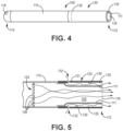
- FIG. 4 is a side-elevation schematic diagram of the illustrative inhaler article 100 of FIG. 3 where the protective layer and mouthpiece endcap is removed.
- FIG. 5 is a cross-sectional schematic diagram of an exemplary mouthpiece illustrating the separate air flow paths of the first mouthpiece air channel and the second mouthpiece air channel.
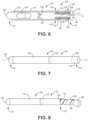
- FIG. 6 is a cross-sectional schematic diagram of another illustrative inhaler article.
- FIG. 7 is a side-elevation schematic diagram of the illustrative inhaler article of FIG. 6.
- FIG. 8 is a side-elevation schematic diagram of the illustrative inhaler article of FIG. 6 where the protective layer and mouthpiece endcap is being removed.
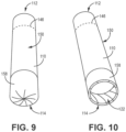
- FIG. 9 is a front perspective view of the illustrative inhaler article of FIG. 6 with an intact deformable element 158.
- FIG. 10 is a front perspective view of the illustrative inhaler article of FIG. 6 with an opened deformable element 158.
- the 10 includes a deformable element 158 defining a distal end 114 of the inhaler article.
- the deformable element 158 deforms to expose an open distal end.
- the deformable element 158 is fan folded at a distal end 114 of the body 110.
- An inhaler article 100 includes a body 110 extending along a longitudinal axis L A from a mouthpiece end 112 to a distal end 114.
- a capsule cavity 122 may be within the body 110 bounded downstream by a mouthpiece 120.
- a separator 124 may be between the capsule cavity 122 and the mouthpiece 120 including at least one aperture 126 to form an air flow path from the capsule cavity 122 to the mouthpiece 120.
- a first mouthpiece air channel 125 may extend from the distal air inlet 118, through the capsule cavity 122 to the mouthpiece air outlet 116.
- a second mouthpiece air channel 135 may extend from a point downstream of the separator 124 to the mouthpiece air outlet 116.
- the second mouthpiece air channel 135 may be separate from the first mouthpiece air channel 125.
- a coating layer of flavour 130 may be disposed on a surface of the second mouthpiece air channel 135 and a protective layer 140 may be disposed on the coating layer of flavour 130.
- the second mouthpiece air channel 135 has an air inlet 132 that extends though the body 110 of the inhaler 100.
- the second mouthpiece air channel 135 has an air inlet 132 that may extend though the mouthpiece 120.
- the second mouthpiece air channel 135 has an air inlet 132 that may extend through the sidewall of the mouthpiece 120.
- the second mouthpiece air channel 135 air inlet 132 may be formed of a plurality of holes or apertures located circumferentially about the mouthpiece 120.
- the first mouthpiece air channel 125 may be coaxial with the second mouthpiece air channel 135.
- the first mouthpiece air channel 125 and the second mouthpiece air channel 135 may be coaxial with the longitudinal axis L A of the inhaler article body 110.
- the first mouthpiece air channel 125 may be coaxial and parallel with the second mouthpiece air channel 135.
- the second mouthpiece air channel 135 may be formed by disposing the mouthpiece 120 about a reduced diameter portion 111 of the inhaler body 110.
- the shaped, educed diameter, or narrowed portion 111 of the body may extend along the mouthpiece region to the mouthpiece end 112 of the inhaler article 100.
- the mouthpiece 120 may fit over the reduced diameter portion 111 of the inhaler body 110 to form the second mouthpiece air channel 135.
- the second mouthpiece air channel 135 may define an annular void space between the mouthpiece inner surface 121 and the external surface of the reduced diameter portion 111 of the inhaler body 110.
- the coating layer of flavour 130 may contact an inner diameter surface 121 of the mouthpiece 120.
- the mouthpiece 120 may be a replaceable element on the inhaler body 100. Thus a user may remove a mouthpiece 120 having a depleted coating layer of flavour 130 and place a different or refreshed mouthpiece 120 over the reduced diameter portion 111 and onto the inhaler body 110.
- the protective layer 140 may adhere to the coating layer of flavour 130 and the protective layer 140 may defines a cylinder being coaxial with the body 110 longitudinal axis L A .
- a mouthpiece endcap 145 may seal the mouthpiece air outlet 116, the mouthpiece endcap 145 may be configured to be removable from the mouthpiece 120 to expose the mouthpiece air outlet 116.
- the protective layer 140 may be fixed to the mouthpiece endcap 145 and configured to be removed from the mouthpiece 120 with the mouthpiece endcap 145.
- the protective layer 140 may defines a spiral configuration when removed from the mouthpiece 120, as illustrated in FIG. 3 .
- the protective layer 140 may seal the air inlet 132 of the second mouthpiece air channel 135.
- the protective layer 140 may extend from the mouthpiece endcap 145 along the coating layer of flavour 130 and over the air inlet 132 of the second mouthpiece air channel 135 to provide a barrier and reduce or prevent migration of the flavour material of the coating layer of flavour 130.
- a circumferential line of weakness 146 forms an interface between the mouthpiece endcap 145 and the mouthpiece end 112. A user may separate the mouthpiece endcap 145from the mouthpiece 120 at the circumferential line of weakness 146.
- a capsule 150 may be disposed within the capsule cavity 122.
- the capsule 150 may be replaceable by removing the distal end 114 of the inhaler article 100 or the mouthpiece 120 and removing or inserting a capsule 150.
- the distal end 114 air inlet 118 may initiate rotational or swirling airflow into the capsule cavity to rotate or spin the capsule 150 and release dry powder particles into the airflow.
- airflow from the capsule cavity containing entrained dry powder particles pass through the separator and out the mouthpiece air outlet 116 along the first air channel 125.
- a separate air flow passes through the body 110 of the inhaler into the second air channel 135 where flavour volatizes into that airflow and out the mouthpiece air outlet 116 along the second air channel 135.
- the second air channel 135 may provide a flavour ventilation airflow that is separate and isolated from the airflow from the capsule cavity containing entrained dry powder particles that pass through the first airflow channel 125.
- dry powder particles and flavour do not contact each other within the inhaler article 100. Dry powder particles and flavour contact each other only once they have exited the inhaler article 100.
- Airflow along the first airflow channel 125 may be parallel and coaxial with the separate airflow along the second air channel 135. Airflows from the first airflow channel 125 and the second air channel 135 may combine once they exit the inhaler article 100.
Landscapes
- Health & Medical Sciences (AREA)
- Engineering & Computer Science (AREA)
- Bioinformatics & Cheminformatics (AREA)
- Pulmonology (AREA)
- Anesthesiology (AREA)
- Biomedical Technology (AREA)
- Heart & Thoracic Surgery (AREA)
- Hematology (AREA)
- Life Sciences & Earth Sciences (AREA)
- Animal Behavior & Ethology (AREA)
- General Health & Medical Sciences (AREA)
- Public Health (AREA)
- Veterinary Medicine (AREA)
- Medicinal Preparation (AREA)
Claims (15)
- Inhalatorartikel (100), umfassend:einen Körper (110), der sich entlang einer Längsachse (LA) von einem Mundstückende (112) zu einem distalen Ende (114) erstreckt;einen Kapselhohlraum (122) innerhalb des Körpers, der stromabwärts durch ein Mundstück (120) begrenzt ist;einen Lufteinlass (118) an dem distalen Ende;einen Luftauslass (116) an dem Mundstückende;einen Separator (124) zwischen dem Kapselhohlraum und dem Mundstück, der wenigstens eine Öffnung (126) umfasst, um einen Luftströmungsweg von dem Kapselhohlraum zu dem Mundstück zu bilden;einen ersten Mundstückluftkanal (125), der sich von dem distalen Lufteinlass durch den Kapselhohlraum zu dem Mundstückluftauslass erstreckt;dadurch gekennzeichnet, dass der Inhalatorartikel ferner einen zweiten Mundstückluftkanal (135) aufweist, der sich von einem dem Separator nachgelagerten Punkt zu dem Mundstückluftauslass erstreckt, wobei der zweite Mundstückluftkanal von dem ersten Mundstückluftkanal getrennt ist; und;eine Geschmacksstoffüberzugschicht (130), die auf einer Fläche des zweiten Mundstückluftkanals angeordnet ist, und eine Schutzschicht (140), die auf der Geschmacksstoffüberzugschicht angeordnet ist.
- Inhalatorartikel (100) nach Anspruch 1, wobei die Geschmacksstoffüberzugsschicht (130) wenigstens einen Abschnitt des zweiten Mundstückluftkanals (135) definiert.
- Inhalatorartikel (100) nach einem beliebigen vorhergehenden Anspruch, wobei der zweite Mundstückluftkanal (135) einen sich durch den Körper (110) des Inhalators erstreckenden Lufteinlass (132) aufweist.
- Inhalatorartikel (100) nach einem beliebigen vorhergehenden Anspruch, wobei der zweite Mundstückluftkanal (135) einen sich durch das Mundstück (120) erstreckenden Lufteinlass (132) aufweist.
- Inhalatorartikel (100) nach einem beliebigen vorhergehenden Anspruch, wobei die Geschmacksstoffüberzugsschicht (130) eine Gelschicht bildet.
- Inhalatorartikel (100) nach einem beliebigen vorhergehenden Anspruch, wobei der Körper (110) einen verengten Abschnitt (111) definiert, der sich zu dem Mundstückende (112) erstreckt, und das Mundstück (120) um den verengten Abschnitt angeordnet ist, und das Mundstück und der verengte Abschnitt den zweiten Mundstückluftkanal (135) bilden.
- Inhalatorartikel (100) nach Anspruch 6, wobei das Mundstück (120) von dem Körper (110) des Inhalatorartikels entfernbar ist und die Geschmacksstoffüberzugsschicht (130) auf einer Innenfläche (121) des Mundstücks angeordnet ist.
- Inhalatorartikel (100) nach einem beliebigen vorhergehenden Anspruch, wobei die Schutzschicht (140) an der Geschmacksstoffüberzugsschicht (130) haftet und die Schutzschicht einen Zylinder definiert, der koaxial zu der Längsachse (LA) des Körpers ist.
- Inhalatorartikel (100) nach einem beliebigen vorhergehenden Anspruch, wobei die Schutzschicht (140) Folie, Papier, Polymer oder Kombinationen davon umfasst.
- Inhalatorartikel (100) nach einem beliebigen vorhergehenden Anspruch, ferner umfassend eine Mundstück-Endkappe (145), die den Mundstückluftauslass (116) abdichtet, wobei die Mundstück-Endkappe als von dem Mundstückelement entfernbar ausgelegt ist, um den Mundstückluftauslass freizulegen, und die Schutzschicht (140) an der Mundstück-Endkappe befestigt und ausgelegt ist, mit der Mundstück-Endkappe von dem Mundstückelement entfernt zu werden.
- Inhalatorartikel (100) nach Anspruch 10, wobei die Schutzschicht (140) eine spiralförmige Ausgestaltung definiert, wenn sie von dem Mundstückelement (120) entfernt wird.
- Inhalatorartikel (100) nach einem beliebigen der Ansprüche 10 bis 11, ferner umfassend eine umlaufende Schwächelinie (146), die eine Schnittstelle zwischen der Mundstück-Endkappe (145) und dem Mundstückende (112) bildet.
- Inhalatorartikel (100) nach einem beliebigen der Ansprüche 10 bis 12, wobei die Mundstück-Endkappe (145) einen Außendurchmesser aufweist, der gleich dem Außendurchmesser des Inhalatorartikelkörpers (110) ist, und die Mundstück-Endkappe koaxial zu dem Inhalatorartikelkörper ist.
- Inhalatorartikel (100) nach einem beliebigen vorhergehenden Anspruch, ferner umfassend eine innerhalb des Kapselhohlraums (122) angeordnete Kapsel (150), wobei die Kapsel (150) bevorzugt pharmazeutisch wirksame Partikel enthält, die Nikotin umfassen, wobei die pharmazeutisch wirksamen Partikel einen mittleren aerodynamischen Massedurchmesser von etwa 5 Mikrometer oder weniger oder in einem Bereich von etwa 0,5 Mikrometer bis etwa 4 Mikrometer oder in einem Bereich von etwa 1 Mikrometer bis etwa 3 Mikrometer aufweisen.
- Inhalatorartikel (100) nach einem beliebigen vorhergehenden Anspruch, ferner umfassend ein verformbares Element (158), das ein distales Ende (114) des Inhalatorartikels definiert, wobei sich das verformbare Element verformt, um ein offenes distales Ende freizulegen, und wobei das verformbare Element (158) bevorzugt an einem distalen Ende (114) des Körpers (110) fächerförmig gefaltet ist.
Applications Claiming Priority (2)
| Application Number | Priority Date | Filing Date | Title |
|---|---|---|---|
| EP20159619 | 2020-02-26 | ||
| PCT/IB2021/051524 WO2021171182A1 (en) | 2020-02-26 | 2021-02-23 | Inhaler mouthpiece with separate flavour air channel |
Publications (3)
| Publication Number | Publication Date |
|---|---|
| EP4110441A1 EP4110441A1 (de) | 2023-01-04 |
| EP4110441C0 EP4110441C0 (de) | 2023-12-13 |
| EP4110441B1 true EP4110441B1 (de) | 2023-12-13 |
Family
ID=69740281
Family Applications (1)
| Application Number | Title | Priority Date | Filing Date |
|---|---|---|---|
| EP21707806.2A Active EP4110441B1 (de) | 2020-02-26 | 2021-02-23 | Inhalatormundstück mit getrenntem aromaluftkanal |
Country Status (7)
| Country | Link |
|---|---|
| US (1) | US12310422B2 (de) |
| EP (1) | EP4110441B1 (de) |
| JP (1) | JP7585332B2 (de) |
| KR (1) | KR20220144799A (de) |
| CN (1) | CN115038485B (de) |
| BR (1) | BR112022014726A2 (de) |
| WO (1) | WO2021171182A1 (de) |
Families Citing this family (7)
| Publication number | Priority date | Publication date | Assignee | Title |
|---|---|---|---|---|
| US11206869B2 (en) | 2017-03-17 | 2021-12-28 | Ryan Selby | Closed bottom vaporizer pod |
| BR112022016859A2 (pt) * | 2020-02-26 | 2022-10-25 | Philip Morris Products Sa | Bocal de inalador com elemento aromatizante |
| CN115316477B (zh) * | 2022-07-18 | 2023-10-27 | 李博文 | 一种巧克力风味可吸食气溶胶制品的制作方法 |
| KR20240162737A (ko) * | 2023-05-09 | 2024-11-18 | 주식회사 케이티앤지 | 파우더 카트리지를 포함하는 흡입기 |
| WO2025026167A1 (zh) * | 2023-07-28 | 2025-02-06 | 深圳市斯科尔科技股份有限公司 | 一种雾化装置及雾化设备 |
| WO2025052299A1 (en) * | 2023-09-08 | 2025-03-13 | Philip Morris Products S.A. | Hybrid aerosol and powder generating consumable article and system |
| US12207686B1 (en) | 2024-09-06 | 2025-01-28 | My Next Idea, LLC | Vortexer for cap of personal vaporizer |
Family Cites Families (15)
| Publication number | Priority date | Publication date | Assignee | Title |
|---|---|---|---|---|
| US5020548A (en) * | 1985-08-26 | 1991-06-04 | R. J. Reynolds Tobacco Company | Smoking article with improved fuel element |
| GB2461008B (en) | 2006-12-08 | 2011-08-10 | Exchange Supplies Ltd | Nicotine inhalation device |
| AT508244B1 (de) | 2010-03-10 | 2010-12-15 | Helmut Dr Buchberger | Inhalatorkomponente |
| US20140224248A1 (en) * | 2011-05-11 | 2014-08-14 | Aerodesigns, Inc. | Aerosol delivery apparatus |
| PL2712643T3 (pl) * | 2012-09-26 | 2018-08-31 | Boehringer Ingelheim International Gmbh | Inhalator |
| US20150351456A1 (en) * | 2013-01-08 | 2015-12-10 | L. Perrigo Company | Electronic cigarette |
| TWI651055B (zh) * | 2013-10-08 | 2019-02-21 | 傑提國際公司 | 噴霧產生裝置之噴霧轉移適配器及噴霧產生裝置中轉移噴霧方法 |
| US9839238B2 (en) * | 2014-02-28 | 2017-12-12 | Rai Strategic Holdings, Inc. | Control body for an electronic smoking article |
| US11338099B2 (en) | 2014-12-24 | 2022-05-24 | Philip Morris Products S.A. | Nicotine powder delivery system |
| KR102641134B1 (ko) | 2015-04-15 | 2024-02-28 | 필립모리스 프로덕츠 에스.에이. | 흡입 디바이스를 위한 향료 요소 |
| MX2018002028A (es) * | 2015-08-21 | 2018-06-15 | Philip Morris Products Sa | Unidad de cartucho para un sistema generador de aerosol y un sistema generador de aerosol que comprende una unidad de cartucho. |
| US20170055576A1 (en) * | 2015-08-31 | 2017-03-02 | R. J. Reynolds Tobacco Company | Smoking article |
| CN109661182B (zh) | 2016-08-26 | 2022-01-11 | 日本烟草产业株式会社 | 非燃烧型香味吸取器 |
| JP7061123B2 (ja) * | 2016-11-30 | 2022-04-27 | フィリップ・モーリス・プロダクツ・ソシエテ・アノニム | サイズ設定された空洞を備えた吸入器 |
| KR102330291B1 (ko) * | 2018-07-04 | 2021-11-24 | 주식회사 케이티앤지 | 궐련 |
-
2021
- 2021-02-23 US US17/801,859 patent/US12310422B2/en active Active
- 2021-02-23 CN CN202180012258.1A patent/CN115038485B/zh active Active
- 2021-02-23 KR KR1020227026587A patent/KR20220144799A/ko active Pending
- 2021-02-23 EP EP21707806.2A patent/EP4110441B1/de active Active
- 2021-02-23 WO PCT/IB2021/051524 patent/WO2021171182A1/en not_active Ceased
- 2021-02-23 JP JP2022549264A patent/JP7585332B2/ja active Active
- 2021-02-23 BR BR112022014726A patent/BR112022014726A2/pt unknown
Also Published As
| Publication number | Publication date |
|---|---|
| CN115038485A (zh) | 2022-09-09 |
| US20230092745A1 (en) | 2023-03-23 |
| US12310422B2 (en) | 2025-05-27 |
| JP7585332B2 (ja) | 2024-11-18 |
| BR112022014726A2 (pt) | 2022-10-11 |
| CN115038485B (zh) | 2025-12-09 |
| WO2021171182A1 (en) | 2021-09-02 |
| KR20220144799A (ko) | 2022-10-27 |
| EP4110441C0 (de) | 2023-12-13 |
| EP4110441A1 (de) | 2023-01-04 |
| JP2023515008A (ja) | 2023-04-12 |
Similar Documents
| Publication | Publication Date | Title |
|---|---|---|
| EP4110441B1 (de) | Inhalatormundstück mit getrenntem aromaluftkanal | |
| US11273268B2 (en) | Nicotine inhaler system | |
| EP3393565B1 (de) | Nikotinpulverausgabesystem | |
| EP3548125B1 (de) | Inhalator mit wirbelendstopfen | |
| EP3548126B1 (de) | Inhalator mit angepasster kavität | |
| EP3700611B1 (de) | Durchstechzubehör für inhalatorartikel und system | |
| EP3481472B1 (de) | Nikotinpartikelausgabeverbrauchselement | |
| EP3700376B1 (de) | Inhalator mit begrenzungselement | |
| EP4110440B1 (de) | Inhalatormundstück mit aromaelement | |
| RU2832975C1 (ru) | Мундштук ингалятора с отдельным каналом для ароматизированного воздуха | |
| RU2833348C1 (ru) | Мундштук ингалятора с ароматическим элементом | |
| HK40004840A (en) | Nicotine particle delivery consumable | |
| HK40004840B (en) | Nicotine particle delivery consumable | |
| NZ747468A (en) | Nicotine particle delivery consumable |
Legal Events
| Date | Code | Title | Description |
|---|---|---|---|
| STAA | Information on the status of an ep patent application or granted ep patent |
Free format text: STATUS: UNKNOWN |
|
| STAA | Information on the status of an ep patent application or granted ep patent |
Free format text: STATUS: THE INTERNATIONAL PUBLICATION HAS BEEN MADE |
|
| PUAI | Public reference made under article 153(3) epc to a published international application that has entered the european phase |
Free format text: ORIGINAL CODE: 0009012 |
|
| STAA | Information on the status of an ep patent application or granted ep patent |
Free format text: STATUS: REQUEST FOR EXAMINATION WAS MADE |
|
| 17P | Request for examination filed |
Effective date: 20220817 |
|
| AK | Designated contracting states |
Kind code of ref document: A1 Designated state(s): AL AT BE BG CH CY CZ DE DK EE ES FI FR GB GR HR HU IE IS IT LI LT LU LV MC MK MT NL NO PL PT RO RS SE SI SK SM TR |
|
| DAV | Request for validation of the european patent (deleted) | ||
| DAX | Request for extension of the european patent (deleted) | ||
| REG | Reference to a national code |
Ref country code: DE Ref legal event code: R079 Free format text: PREVIOUS MAIN CLASS: A61M0015000000 Ipc: A24F0042200000 Ref country code: DE Ref legal event code: R079 Ref document number: 602021007692 Country of ref document: DE Free format text: PREVIOUS MAIN CLASS: A61M0015000000 Ipc: A24F0042200000 |
|
| GRAP | Despatch of communication of intention to grant a patent |
Free format text: ORIGINAL CODE: EPIDOSNIGR1 |
|
| STAA | Information on the status of an ep patent application or granted ep patent |
Free format text: STATUS: GRANT OF PATENT IS INTENDED |
|
| RIC1 | Information provided on ipc code assigned before grant |
Ipc: A61M 15/06 20060101ALI20230620BHEP Ipc: A61M 15/00 20060101ALI20230620BHEP Ipc: A24F 42/20 20200101AFI20230620BHEP |
|
| INTG | Intention to grant announced |
Effective date: 20230707 |
|
| GRAS | Grant fee paid |
Free format text: ORIGINAL CODE: EPIDOSNIGR3 |
|
| GRAA | (expected) grant |
Free format text: ORIGINAL CODE: 0009210 |
|
| STAA | Information on the status of an ep patent application or granted ep patent |
Free format text: STATUS: THE PATENT HAS BEEN GRANTED |
|
| AK | Designated contracting states |
Kind code of ref document: B1 Designated state(s): AL AT BE BG CH CY CZ DE DK EE ES FI FR GB GR HR HU IE IS IT LI LT LU LV MC MK MT NL NO PL PT RO RS SE SI SK SM TR |
|
| REG | Reference to a national code |
Ref country code: GB Ref legal event code: FG4D |
|
| REG | Reference to a national code |
Ref country code: CH Ref legal event code: EP |
|
| REG | Reference to a national code |
Ref country code: DE Ref legal event code: R096 Ref document number: 602021007692 Country of ref document: DE |
|
| REG | Reference to a national code |
Ref country code: IE Ref legal event code: FG4D |
|
| U01 | Request for unitary effect filed |
Effective date: 20231213 |
|
| U07 | Unitary effect registered |
Designated state(s): AT BE BG DE DK EE FI FR IT LT LU LV MT NL PT SE SI Effective date: 20231220 |
|
| U20 | Renewal fee for the european patent with unitary effect paid |
Year of fee payment: 4 Effective date: 20240222 |
|
| PG25 | Lapsed in a contracting state [announced via postgrant information from national office to epo] |
Ref country code: GR Free format text: LAPSE BECAUSE OF FAILURE TO SUBMIT A TRANSLATION OF THE DESCRIPTION OR TO PAY THE FEE WITHIN THE PRESCRIBED TIME-LIMIT Effective date: 20240314 |
|
| PG25 | Lapsed in a contracting state [announced via postgrant information from national office to epo] |
Ref country code: ES Free format text: LAPSE BECAUSE OF FAILURE TO SUBMIT A TRANSLATION OF THE DESCRIPTION OR TO PAY THE FEE WITHIN THE PRESCRIBED TIME-LIMIT Effective date: 20231213 |
|
| PG25 | Lapsed in a contracting state [announced via postgrant information from national office to epo] |
Ref country code: GR Free format text: LAPSE BECAUSE OF FAILURE TO SUBMIT A TRANSLATION OF THE DESCRIPTION OR TO PAY THE FEE WITHIN THE PRESCRIBED TIME-LIMIT Effective date: 20240314 Ref country code: ES Free format text: LAPSE BECAUSE OF FAILURE TO SUBMIT A TRANSLATION OF THE DESCRIPTION OR TO PAY THE FEE WITHIN THE PRESCRIBED TIME-LIMIT Effective date: 20231213 |
|
| PG25 | Lapsed in a contracting state [announced via postgrant information from national office to epo] |
Ref country code: RS Free format text: LAPSE BECAUSE OF FAILURE TO SUBMIT A TRANSLATION OF THE DESCRIPTION OR TO PAY THE FEE WITHIN THE PRESCRIBED TIME-LIMIT Effective date: 20231213 Ref country code: NO Free format text: LAPSE BECAUSE OF FAILURE TO SUBMIT A TRANSLATION OF THE DESCRIPTION OR TO PAY THE FEE WITHIN THE PRESCRIBED TIME-LIMIT Effective date: 20240313 Ref country code: HR Free format text: LAPSE BECAUSE OF FAILURE TO SUBMIT A TRANSLATION OF THE DESCRIPTION OR TO PAY THE FEE WITHIN THE PRESCRIBED TIME-LIMIT Effective date: 20231213 |
|
| PG25 | Lapsed in a contracting state [announced via postgrant information from national office to epo] |
Ref country code: IS Free format text: LAPSE BECAUSE OF FAILURE TO SUBMIT A TRANSLATION OF THE DESCRIPTION OR TO PAY THE FEE WITHIN THE PRESCRIBED TIME-LIMIT Effective date: 20240413 |
|
| PG25 | Lapsed in a contracting state [announced via postgrant information from national office to epo] |
Ref country code: CZ Free format text: LAPSE BECAUSE OF FAILURE TO SUBMIT A TRANSLATION OF THE DESCRIPTION OR TO PAY THE FEE WITHIN THE PRESCRIBED TIME-LIMIT Effective date: 20231213 |
|
| PG25 | Lapsed in a contracting state [announced via postgrant information from national office to epo] |
Ref country code: SK Free format text: LAPSE BECAUSE OF FAILURE TO SUBMIT A TRANSLATION OF THE DESCRIPTION OR TO PAY THE FEE WITHIN THE PRESCRIBED TIME-LIMIT Effective date: 20231213 |
|
| PG25 | Lapsed in a contracting state [announced via postgrant information from national office to epo] |
Ref country code: SM Free format text: LAPSE BECAUSE OF FAILURE TO SUBMIT A TRANSLATION OF THE DESCRIPTION OR TO PAY THE FEE WITHIN THE PRESCRIBED TIME-LIMIT Effective date: 20231213 Ref country code: SK Free format text: LAPSE BECAUSE OF FAILURE TO SUBMIT A TRANSLATION OF THE DESCRIPTION OR TO PAY THE FEE WITHIN THE PRESCRIBED TIME-LIMIT Effective date: 20231213 Ref country code: RO Free format text: LAPSE BECAUSE OF FAILURE TO SUBMIT A TRANSLATION OF THE DESCRIPTION OR TO PAY THE FEE WITHIN THE PRESCRIBED TIME-LIMIT Effective date: 20231213 Ref country code: IS Free format text: LAPSE BECAUSE OF FAILURE TO SUBMIT A TRANSLATION OF THE DESCRIPTION OR TO PAY THE FEE WITHIN THE PRESCRIBED TIME-LIMIT Effective date: 20240413 Ref country code: CZ Free format text: LAPSE BECAUSE OF FAILURE TO SUBMIT A TRANSLATION OF THE DESCRIPTION OR TO PAY THE FEE WITHIN THE PRESCRIBED TIME-LIMIT Effective date: 20231213 |
|
| PG25 | Lapsed in a contracting state [announced via postgrant information from national office to epo] |
Ref country code: PL Free format text: LAPSE BECAUSE OF FAILURE TO SUBMIT A TRANSLATION OF THE DESCRIPTION OR TO PAY THE FEE WITHIN THE PRESCRIBED TIME-LIMIT Effective date: 20231213 |
|
| U1N | Appointed representative for the unitary patent procedure changed after the registration of the unitary effect |
Representative=s name: REDDIE & GROSE LLP; GB |
|
| PG25 | Lapsed in a contracting state [announced via postgrant information from national office to epo] |
Ref country code: PL Free format text: LAPSE BECAUSE OF FAILURE TO SUBMIT A TRANSLATION OF THE DESCRIPTION OR TO PAY THE FEE WITHIN THE PRESCRIBED TIME-LIMIT Effective date: 20231213 |
|
| REG | Reference to a national code |
Ref country code: DE Ref legal event code: R097 Ref document number: 602021007692 Country of ref document: DE |
|
| PG25 | Lapsed in a contracting state [announced via postgrant information from national office to epo] |
Ref country code: MC Free format text: LAPSE BECAUSE OF FAILURE TO SUBMIT A TRANSLATION OF THE DESCRIPTION OR TO PAY THE FEE WITHIN THE PRESCRIBED TIME-LIMIT Effective date: 20231213 |
|
| PLBE | No opposition filed within time limit |
Free format text: ORIGINAL CODE: 0009261 |
|
| STAA | Information on the status of an ep patent application or granted ep patent |
Free format text: STATUS: NO OPPOSITION FILED WITHIN TIME LIMIT |
|
| 26N | No opposition filed |
Effective date: 20240916 |
|
| PG25 | Lapsed in a contracting state [announced via postgrant information from national office to epo] |
Ref country code: IE Free format text: LAPSE BECAUSE OF NON-PAYMENT OF DUE FEES Effective date: 20240223 |
|
| PG25 | Lapsed in a contracting state [announced via postgrant information from national office to epo] |
Ref country code: IE Free format text: LAPSE BECAUSE OF NON-PAYMENT OF DUE FEES Effective date: 20240223 |
|
| U20 | Renewal fee for the european patent with unitary effect paid |
Year of fee payment: 5 Effective date: 20250221 |
|
| PGFP | Annual fee paid to national office [announced via postgrant information from national office to epo] |
Ref country code: CH Payment date: 20250301 Year of fee payment: 5 |
|
| PGFP | Annual fee paid to national office [announced via postgrant information from national office to epo] |
Ref country code: GB Payment date: 20250220 Year of fee payment: 5 |
|
| PG25 | Lapsed in a contracting state [announced via postgrant information from national office to epo] |
Ref country code: CY Free format text: LAPSE BECAUSE OF FAILURE TO SUBMIT A TRANSLATION OF THE DESCRIPTION OR TO PAY THE FEE WITHIN THE PRESCRIBED TIME-LIMIT; INVALID AB INITIO Effective date: 20210223 |
|
| PG25 | Lapsed in a contracting state [announced via postgrant information from national office to epo] |
Ref country code: HU Free format text: LAPSE BECAUSE OF FAILURE TO SUBMIT A TRANSLATION OF THE DESCRIPTION OR TO PAY THE FEE WITHIN THE PRESCRIBED TIME-LIMIT; INVALID AB INITIO Effective date: 20210223 |
|
| PG25 | Lapsed in a contracting state [announced via postgrant information from national office to epo] |
Ref country code: TR Free format text: LAPSE BECAUSE OF FAILURE TO SUBMIT A TRANSLATION OF THE DESCRIPTION OR TO PAY THE FEE WITHIN THE PRESCRIBED TIME-LIMIT Effective date: 20231213 |