EP4110237B1 - Kniegelenkprothese mit elektronisch gesteuertem getriebe - Google Patents
Kniegelenkprothese mit elektronisch gesteuertem getriebe Download PDFInfo
- Publication number
- EP4110237B1 EP4110237B1 EP21761390.0A EP21761390A EP4110237B1 EP 4110237 B1 EP4110237 B1 EP 4110237B1 EP 21761390 A EP21761390 A EP 21761390A EP 4110237 B1 EP4110237 B1 EP 4110237B1
- Authority
- EP
- European Patent Office
- Prior art keywords
- clutch
- gear
- ring
- state
- orthosis
- Prior art date
- Legal status (The legal status is an assumption and is not a legal conclusion. Google has not performed a legal analysis and makes no representation as to the accuracy of the status listed.)
- Active
Links
Images



Classifications
-
- A—HUMAN NECESSITIES
- A61—MEDICAL OR VETERINARY SCIENCE; HYGIENE
- A61F—FILTERS IMPLANTABLE INTO BLOOD VESSELS; PROSTHESES; DEVICES PROVIDING PATENCY TO, OR PREVENTING COLLAPSING OF, TUBULAR STRUCTURES OF THE BODY, e.g. STENTS; ORTHOPAEDIC, NURSING OR CONTRACEPTIVE DEVICES; FOMENTATION; TREATMENT OR PROTECTION OF EYES OR EARS; BANDAGES, DRESSINGS OR ABSORBENT PADS; FIRST-AID KITS
- A61F2/00—Filters implantable into blood vessels; Prostheses, i.e. artificial substitutes or replacements for parts of the body; Appliances for connecting them with the body; Devices providing patency to, or preventing collapsing of, tubular structures of the body, e.g. stents
- A61F2/50—Prostheses not implantable in the body
- A61F2/60—Artificial legs or feet or parts thereof
-
- A—HUMAN NECESSITIES
- A61—MEDICAL OR VETERINARY SCIENCE; HYGIENE
- A61F—FILTERS IMPLANTABLE INTO BLOOD VESSELS; PROSTHESES; DEVICES PROVIDING PATENCY TO, OR PREVENTING COLLAPSING OF, TUBULAR STRUCTURES OF THE BODY, e.g. STENTS; ORTHOPAEDIC, NURSING OR CONTRACEPTIVE DEVICES; FOMENTATION; TREATMENT OR PROTECTION OF EYES OR EARS; BANDAGES, DRESSINGS OR ABSORBENT PADS; FIRST-AID KITS
- A61F2/00—Filters implantable into blood vessels; Prostheses, i.e. artificial substitutes or replacements for parts of the body; Appliances for connecting them with the body; Devices providing patency to, or preventing collapsing of, tubular structures of the body, e.g. stents
- A61F2/50—Prostheses not implantable in the body
- A61F2/60—Artificial legs or feet or parts thereof
- A61F2/64—Knee joints
-
- A—HUMAN NECESSITIES
- A61—MEDICAL OR VETERINARY SCIENCE; HYGIENE
- A61F—FILTERS IMPLANTABLE INTO BLOOD VESSELS; PROSTHESES; DEVICES PROVIDING PATENCY TO, OR PREVENTING COLLAPSING OF, TUBULAR STRUCTURES OF THE BODY, e.g. STENTS; ORTHOPAEDIC, NURSING OR CONTRACEPTIVE DEVICES; FOMENTATION; TREATMENT OR PROTECTION OF EYES OR EARS; BANDAGES, DRESSINGS OR ABSORBENT PADS; FIRST-AID KITS
- A61F2/00—Filters implantable into blood vessels; Prostheses, i.e. artificial substitutes or replacements for parts of the body; Appliances for connecting them with the body; Devices providing patency to, or preventing collapsing of, tubular structures of the body, e.g. stents
- A61F2/50—Prostheses not implantable in the body
- A61F2/68—Operating or control means
-
- A—HUMAN NECESSITIES
- A61—MEDICAL OR VETERINARY SCIENCE; HYGIENE
- A61F—FILTERS IMPLANTABLE INTO BLOOD VESSELS; PROSTHESES; DEVICES PROVIDING PATENCY TO, OR PREVENTING COLLAPSING OF, TUBULAR STRUCTURES OF THE BODY, e.g. STENTS; ORTHOPAEDIC, NURSING OR CONTRACEPTIVE DEVICES; FOMENTATION; TREATMENT OR PROTECTION OF EYES OR EARS; BANDAGES, DRESSINGS OR ABSORBENT PADS; FIRST-AID KITS
- A61F2/00—Filters implantable into blood vessels; Prostheses, i.e. artificial substitutes or replacements for parts of the body; Appliances for connecting them with the body; Devices providing patency to, or preventing collapsing of, tubular structures of the body, e.g. stents
- A61F2/50—Prostheses not implantable in the body
- A61F2/68—Operating or control means
- A61F2/70—Operating or control means electrical
-
- A—HUMAN NECESSITIES
- A61—MEDICAL OR VETERINARY SCIENCE; HYGIENE
- A61F—FILTERS IMPLANTABLE INTO BLOOD VESSELS; PROSTHESES; DEVICES PROVIDING PATENCY TO, OR PREVENTING COLLAPSING OF, TUBULAR STRUCTURES OF THE BODY, e.g. STENTS; ORTHOPAEDIC, NURSING OR CONTRACEPTIVE DEVICES; FOMENTATION; TREATMENT OR PROTECTION OF EYES OR EARS; BANDAGES, DRESSINGS OR ABSORBENT PADS; FIRST-AID KITS
- A61F2/00—Filters implantable into blood vessels; Prostheses, i.e. artificial substitutes or replacements for parts of the body; Appliances for connecting them with the body; Devices providing patency to, or preventing collapsing of, tubular structures of the body, e.g. stents
- A61F2/50—Prostheses not implantable in the body
- A61F2002/5016—Prostheses not implantable in the body adjustable
- A61F2002/503—Prostheses not implantable in the body adjustable for adjusting elasticity, flexibility, spring rate or mechanical tension
-
- A—HUMAN NECESSITIES
- A61—MEDICAL OR VETERINARY SCIENCE; HYGIENE
- A61F—FILTERS IMPLANTABLE INTO BLOOD VESSELS; PROSTHESES; DEVICES PROVIDING PATENCY TO, OR PREVENTING COLLAPSING OF, TUBULAR STRUCTURES OF THE BODY, e.g. STENTS; ORTHOPAEDIC, NURSING OR CONTRACEPTIVE DEVICES; FOMENTATION; TREATMENT OR PROTECTION OF EYES OR EARS; BANDAGES, DRESSINGS OR ABSORBENT PADS; FIRST-AID KITS
- A61F2/00—Filters implantable into blood vessels; Prostheses, i.e. artificial substitutes or replacements for parts of the body; Appliances for connecting them with the body; Devices providing patency to, or preventing collapsing of, tubular structures of the body, e.g. stents
- A61F2/50—Prostheses not implantable in the body
- A61F2/68—Operating or control means
- A61F2002/6818—Operating or control means for braking
-
- A—HUMAN NECESSITIES
- A61—MEDICAL OR VETERINARY SCIENCE; HYGIENE
- A61F—FILTERS IMPLANTABLE INTO BLOOD VESSELS; PROSTHESES; DEVICES PROVIDING PATENCY TO, OR PREVENTING COLLAPSING OF, TUBULAR STRUCTURES OF THE BODY, e.g. STENTS; ORTHOPAEDIC, NURSING OR CONTRACEPTIVE DEVICES; FOMENTATION; TREATMENT OR PROTECTION OF EYES OR EARS; BANDAGES, DRESSINGS OR ABSORBENT PADS; FIRST-AID KITS
- A61F2/00—Filters implantable into blood vessels; Prostheses, i.e. artificial substitutes or replacements for parts of the body; Appliances for connecting them with the body; Devices providing patency to, or preventing collapsing of, tubular structures of the body, e.g. stents
- A61F2/50—Prostheses not implantable in the body
- A61F2/68—Operating or control means
- A61F2002/6845—Clutches
-
- A—HUMAN NECESSITIES
- A61—MEDICAL OR VETERINARY SCIENCE; HYGIENE
- A61F—FILTERS IMPLANTABLE INTO BLOOD VESSELS; PROSTHESES; DEVICES PROVIDING PATENCY TO, OR PREVENTING COLLAPSING OF, TUBULAR STRUCTURES OF THE BODY, e.g. STENTS; ORTHOPAEDIC, NURSING OR CONTRACEPTIVE DEVICES; FOMENTATION; TREATMENT OR PROTECTION OF EYES OR EARS; BANDAGES, DRESSINGS OR ABSORBENT PADS; FIRST-AID KITS
- A61F2/00—Filters implantable into blood vessels; Prostheses, i.e. artificial substitutes or replacements for parts of the body; Appliances for connecting them with the body; Devices providing patency to, or preventing collapsing of, tubular structures of the body, e.g. stents
- A61F2/50—Prostheses not implantable in the body
- A61F2/68—Operating or control means
- A61F2/70—Operating or control means electrical
- A61F2002/701—Operating or control means electrical operated by electrically controlled means, e.g. solenoids or torque motors
-
- A—HUMAN NECESSITIES
- A61—MEDICAL OR VETERINARY SCIENCE; HYGIENE
- A61F—FILTERS IMPLANTABLE INTO BLOOD VESSELS; PROSTHESES; DEVICES PROVIDING PATENCY TO, OR PREVENTING COLLAPSING OF, TUBULAR STRUCTURES OF THE BODY, e.g. STENTS; ORTHOPAEDIC, NURSING OR CONTRACEPTIVE DEVICES; FOMENTATION; TREATMENT OR PROTECTION OF EYES OR EARS; BANDAGES, DRESSINGS OR ABSORBENT PADS; FIRST-AID KITS
- A61F2/00—Filters implantable into blood vessels; Prostheses, i.e. artificial substitutes or replacements for parts of the body; Appliances for connecting them with the body; Devices providing patency to, or preventing collapsing of, tubular structures of the body, e.g. stents
- A61F2/50—Prostheses not implantable in the body
- A61F2/76—Means for assembling, fitting or testing prostheses, e.g. for measuring or balancing, e.g. alignment means
- A61F2002/7615—Measuring means
- A61F2002/7635—Measuring means for measuring force, pressure or mechanical tension
-
- A—HUMAN NECESSITIES
- A61—MEDICAL OR VETERINARY SCIENCE; HYGIENE
- A61F—FILTERS IMPLANTABLE INTO BLOOD VESSELS; PROSTHESES; DEVICES PROVIDING PATENCY TO, OR PREVENTING COLLAPSING OF, TUBULAR STRUCTURES OF THE BODY, e.g. STENTS; ORTHOPAEDIC, NURSING OR CONTRACEPTIVE DEVICES; FOMENTATION; TREATMENT OR PROTECTION OF EYES OR EARS; BANDAGES, DRESSINGS OR ABSORBENT PADS; FIRST-AID KITS
- A61F2/00—Filters implantable into blood vessels; Prostheses, i.e. artificial substitutes or replacements for parts of the body; Appliances for connecting them with the body; Devices providing patency to, or preventing collapsing of, tubular structures of the body, e.g. stents
- A61F2/50—Prostheses not implantable in the body
- A61F2/76—Means for assembling, fitting or testing prostheses, e.g. for measuring or balancing, e.g. alignment means
- A61F2002/7615—Measuring means
- A61F2002/764—Measuring means for measuring acceleration
Definitions
- United States patent application US 2013/261766 A disclosed a powered prosthetic thigh that can have a proximal portion configured to couple to a prosthetic hip socket and that can have a distal portion attached to the proximal portion.
- the distal portion can have a distal connector configured to couple to a prosthetic knee.
- the powered prosthetic thigh can also have a computer controlled actuator configured to rotate the prosthetic thigh relative to the prosthetic hip socket.
- a knee prosthesis or orthosis includes at least one moveable joint and a torque modulating unit.
- the torque modulating unit is configured to impose a controllable torque on the at least one moveable joint.
- the torque modulating unit includes at least one of a motor or brake.
- the at least one of the motor or brake coupled to the at least one moveable joint via an electronically-controlled transmission.
- the electronically-controlled transmission is a two-speed transmission.
- the knee prosthesis or orthosis 10 includes at least one moveable joint 12 and a torque modulating unit 14.
- the knee prosthesis or orthosis 10 of FIG. 1 further includes a device control unit 20 that includes at least one accelerometer 22.
- the at least one accelerometer 22 may be located within an inertial measurement sensor (IMU) 24.
- the IMU 24 includes the at least one accelerometer 22 and at least one gyroscope 26.
- the IMU may be a multi-axis IMU in one embodiment.
- One non-limiting example of a multi-axis IMU includes a plurality of accelerometers and a plurality of gyroscopes.
- the knee prosthesis or orthosis 10 of FIG. 1 further includes a load cell 28 and a knee joint encoder 30.
- the load cell 28 assists in measuring the load of the knee prosthesis or orthosis 10.
- the knee joint encoder 30 assists in measuring knee joint angle.
- the torque modulating unit 14 is configured to impose a controllable torque on the at least moveable joint 12.
- the knee prosthesis or orthosis 10 of FIG. 1 also further includes joints 34, 36 as shown in FIG. 1 .
- the torque modulating unit 14 includes at least one motor or brake as will be discussed below.
- the at least one motor or brake of the torque modulating unit 14 is coupled to the at least one moveable joint 12 via an electronically-controlled transmission (ECT).
- ECT electronically-controlled transmission
- the two-speed transmission is based on a planetary gear transmission.
- the planetary gear transmission includes at least two transmission stages - an input planetary stage and an output planetary stage.
- the input planetary stage includes at least an input sun gear, an input carrier link, and the output planetary stage includes an output carrier link.
- the stages share a common ring gear (i.e., all stages share the same ring gear). Common ring gear means that the ring gears associated with each stage are rigidly coupled together.
- a sun gear, a carrier link, and at least three or more planet gears are used in each planetary stage (e.g., an input planetary stage and an output planetary stage).
- each of the stages includes a common ring gear.
- the two-speed transmission includes at least a ring clutch and a carrier clutch in one embodiment.
- the ring clutch and the carrier clutch are solenoid-actuated clutches in one embodiment. Both of the ring and the carrier clutches are configured independently to be either in an engaged state or a disengaged state.
- the ring clutch in one embodiment allows the common ring gear to rotate relative to ground.
- ground as used herein includes grounding to a frame, grounding to housing, or the like.
- the ring clutch in one embodiment prevents or inhibits the common gear from rotating relative to ground.
- the carrier clutch in one embodiment allows the input carrier link to rotate relative to ground.
- the carrier clutch in one embodiment prevents or inhibits the input carrier link from rotating relative to ground.
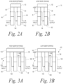
- FIG. 2A a schematic 50 of a high-gear transmission ratio (stance) for a two-stage planetary gear transmission according to the invention is shown.
- FIG. 2B depicts a schematic 70 of a low-gear transmission ratio (swing) for a two-stage planetary gear transmission according to the invention.
- the schematic 50 of FIG. 2A includes a first stage (input) and a second stage (output) of a planetary gear transmission of a high-gear transmission ratio (stance).
- the schematic 70 of FIG. 2A, 2B includes a first stage (input) and a second stage (output) of a planetary gear transmission for a low-gear transmission ratio (swing).
- schematics 50, 70 of FIGS. 2A, 2B both depict exactly two stages.
- Both of the schematics 50, 70 of the planetary gear transmission includes a common ring gear 52, an input planet gear 56, an output planet gear 58, an input sun gear 60, and an output sun gear 62.
- the input planet gear 56 is connected to the output sun gear 62 via an input carrier link 64.
- the output planet gear 58 is connected to an output carrier link 68.
- the input is the input sun gear 62 and the output is the last carrier link (carrier link 68 in schematics 50, 70).
- the input carrier link 64 can be grounded via a carrier clutch.
- the carrier clutch is an electromagnetic clutch.
- the common ring gear 52 is separately grounded by a ring clutch.
- the ring clutch in this embodiment is a unidirectional electromagnetic clutch.
- the carrier and ring clutches can be engaged or disengaged in various combinations to provide: (1) a high-gear transmission ratio appropriate for stance phase; (2) a low-gear transmission ratio appropriate for swing phase; and (3) a combination thereof that enables a low-gear transmission ratio against extension and high-impedance against flexion.
- a planetary gear transmission can have additional stages in other embodiments.
- schematic 150 of FIG. 3A includes a first stage (input), a second stage, and a third stage (output) of a planetary gear transmission of a high-gear transmission ratio (stance).
- FIG. 3B depicts a schematic 170 that includes a first stage (input), a second stage and a third stage (output) of a planetary gear transmission of a low-gear transmission ratio (swing).
- This general transmission configuration is configured to function for a planetary gear transmission with any number of stages provided that the ring gear of each stage is a common ring gear.
- the ring clutch and the carrier clutch are both de-energized.
- the common ring gear in the first state 210 is grounded (only in one direction).
- the transmission is in its high gear against flexion.
- the high-gear transmission ratio is configured to support a weight of the prosthesis or orthosis of a user when standing on the knee prosthesis or orthosis. Because the ring clutch can only engage the transmission unidirectionally, the transmission slips against extension (i.e., does not resist extension movement).
- the unidirectional behavior of the transmission is configured to generate torque against knee flexion.
- the torque modulating unit is in the first state 210 when the prosthesis or orthosis user is standing on the prosthesis or orthosis (stance), providing support against flexion of the knee.
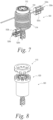
- a ring clutch 400 is shown according to the invention.
- the ring clutch grounds the common ring gear, and is engaged during the stance phase to provide unidirectional holding against knee flexion.
- the ring clutch 400 employs a capstan-type design. It is contemplated that the ring clutch may not include a capstan-type design in other embodiments.
- the spring element 420 applies tension to one end of the wire rope 414, while the other end of the spring element 420 is grounded to the housing by the adjustable anchor point 422.
- the adjustable anchor point 422 is adjustable via a set screw thereon that permits adjustment of the preload tension on the spring element 420.
- the distal ends of the spring element 420 and wire rope 414 are fixed to the solenoid armature 428.
- the solenoid armature 428 is located or positioned within the solenoid stator 432.
Landscapes
- Health & Medical Sciences (AREA)
- Transplantation (AREA)
- Vascular Medicine (AREA)
- Life Sciences & Earth Sciences (AREA)
- Oral & Maxillofacial Surgery (AREA)
- Engineering & Computer Science (AREA)
- Biomedical Technology (AREA)
- Heart & Thoracic Surgery (AREA)
- Veterinary Medicine (AREA)
- Cardiology (AREA)
- Animal Behavior & Ethology (AREA)
- General Health & Medical Sciences (AREA)
- Public Health (AREA)
- Orthopedic Medicine & Surgery (AREA)
- Retarders (AREA)
- Prostheses (AREA)
Claims (15)
- Knieprothese oder -Orthese (10), umfassend:mindestens ein bewegliches Gelenk (12) undeine Drehmomentmodulationseinheit (14, 300), wobei die Drehmomentmodulationseinheit (14, 300) dazu ausgestaltet ist, dem mindestens einen beweglichen Gelenk (12) ein steuerbares Drehmoment aufzuerlegen, wobei die Drehmomentmodulationseinheit (14, 300) einen Motor und/oder eine Bremse (302) aufweist, wobei der Motor und/oder die Bremse (302) über ein elektronisch gesteuertes Getriebe an das mindestens eine bewegliche Gelenk (12) gekoppelt ist, dadurch gekennzeichnet, dass das elektronisch gesteuerte Getriebe ein Zweiganggetriebe ist.
- Knieprothese oder -Orthese (10) nach Anspruch 1, wobei das Zweiganggetriebe eine hohe Getriebeübersetzung und eine niedrige Getriebeübersetzung aufweist, wobei das Zweiganggetriebe dazu ausgestaltet ist, innerhalb einer Schreitperiode während eines Gangzyklus zwischen der hohen Getriebeübersetzung und der niedrigen Getriebeübersetzung zu schalten, wobei der Gangzyklus eine Standphase und eine Schwungphase aufweist,wobei die hohe Getriebeübersetzung eine Verhaltenscharakteristik mit hohem Drehmoment, niedriger Drehzahl und hoher Impedanz bereitstellt, die zu der Standphase des Gangzyklus konfiguriert ist, und wobei die hohe Getriebeübersetzung dazu ausgestaltet ist, ein Gewicht der Prothese oder Orthese (10) eines Benutzers zu stützen, wenn er auf der Knieprothese oder -Orthese (10) steht,wobei die niedrige Getriebeübersetzung eine Verhaltenscharakteristik mit hoher Drehzahl, niedrigem Drehmoment und niedriger Impedanz bereitstellt, die für die Schwungphase des Gangzyklus geeignet ist, und wobei die niedrige Getriebeübersetzung so ausgestaltet ist, dass die Prothese oder Orthese (10) einem Kniegelenk freies Schwingen gestatten kann, wenn die Knieprothese oder -Orthese (10) das Gewicht des Benutzers nicht trägt.
- Knieprothese oder -Orthese (10) nach Anspruch 2, wobei sich die hohe und die niedrige Getriebeübersetzung um mindestens etwa eine Größenordnung unterscheiden.
- Knieprothese oder -Orthese (10) nach Anspruch 2,- wobei die hohe Getriebeübersetzung dazu ausgestaltet ist, ein unidirektionales Verhalten aufzuweisen, wobei das Zweiganggetriebe dazu ausgestaltet ist, ein Drehmoment gegen Knieflexion zu erzeugen, aber bei Widerstand gegen eine Knie-Extension rutscht, und/oder- wobei die niedrige Getriebeübersetzung dazu ausgestaltet ist, ein asymmetrisches Verhalten aufzuweisen, wobei das Zweiganggetriebe dazu ausgestaltet ist, Extension mit einem niedrigen Widerstand zu widerstehen, Flexion jedoch mit einem hohen Widerstand zu widerstehen.
- Knieprothese oder-Orthese (10) nach Anspruch 2, wobei das Zweiganggetriebe dazu ausgestaltet ist, sich in mindestens einem ersten Zustand (210), einem zweiten Zustand (220) oder einem dritten Zustand (230) zu befinden, wobei das Zweiganggetriebe im ersten Zustand (210) die hohe Getriebeübersetzung bereitstellt, wenn es Flexion widersteht oder Extension bereitstellt, während es bei Widerstand gegen Extension oder Bereitstellung von Flexion wenig bis kein Drehmoment bereitstellt, das Zweiganggetriebe im zweiten Zustand (220) die niedrige Getriebeübersetzung bereitstellt, wobei die niedrige Getriebeübersetzung bidirektional ist, und das Zweiganggetriebe im dritten Zustand (230) die niedrige Getriebeübersetzung bereitstellt, wenn es Extension widersteht oder Flexion bereitstellt, während es auch hohen Widerstand bereitstellt, wenn es Flexion widersteht oder Extension bereitstellt, wobei vorzugsweise das Zweiganggetriebe ferner für einen vierten Zustand ausgestaltet ist, wobei das Zweiganggetriebe im vierten Zustand die hohe Getriebeübersetzung bereitstellt, wobei die hohe Getriebeübersetzung bidirektional ist.
- Knieprothese oder -Orthese (10) nach Anspruch 2, wobei das Zweiganggetriebe dazu ausgestaltet ist, sich in mindestens einem neutralen Zustand zu befinden, in dem das Zweiganggetriebe von dem Motor und/oder der Bremse (302) ausgerückt ist.
- Knieprothese oder -Orthese (10) nach Anspruch 2, wobei das Zweiganggetriebe ein Planetengetriebe (310) aufweist, wobei das Planetengetriebe mindestens eine Planeten-Eingangsstufe und eine Planeten-Ausgangsstufe aufweist, wobei die Planeten-Eingangsstufe mindestens ein Eingangssonnenrad (60) und ein Eingangsträgerverbindungsglied (64, 164, 165) aufweist, wobei die Planeten-Ausgangsstufe ein Ausgangsträgerverbindungsglied (68, 168) aufweist,wobei der Motor und/oder die Bremse (302) an das Eingangssonnenrad (60) gekoppelt sind und mindestens ein bewegliches Gelenk (12) direkt oder indirekt an das Ausgangsträgerverbindungsglied (68, 168) gekoppelt ist,wobei das Planetengetriebe ferner ein gemeinsames Hohlrad (52, 412, 512) aufweist,wobei das Zweiganggetriebe mindestens eine Ringkupplung (400, 500, 600) und eine Trägerkupplung aufweist, wobei die Ringkupplung (400, 500, 600) so konfigurierbar ist, dass sie sich in einem eingerückten Zustand oder einem ausgerückten Zustand befindet, wobei die Trägerkupplung so konfigurierbar ist, dass sie sich in einem eingerückten Zustand oder einem ausgerückten Zustand befindet,wobei die Ringkupplung (400, 500, 600) im ausgerückten Zustand dem gemeinsamen Hohlrad (52, 412, 512) gestattet, sich relativ zu Masse zu drehen, und wobei die Ringkupplung (400, 500, 600) im eingerückten Zustand verhindert, dass sich das gemeinsame Zahnrad relativ zu Masse dreht, oder dieses hemmt,wobei die Trägerkupplung im ausgerückten Zustand gestattet, dass sich das Eingangsträgerverbindungsglied (64, 164, 165) relativ zu Masse dreht, und wobei die Trägerkupplung im eingerückten Zustand verhindert, dass sich das Eingangsträgerverbindungsglied (64, 164, 165) relativ zu Masse dreht, oder dieses hemmt.
- Knieprothese oder -Orthese (10) nach Anspruch 7, wobei die Planeten-Eingangsstufe ferner mindestens einen Satz von drei Eingangsplanetenrädern (56) aufweist und die Planeten-Ausgangsstufe ferner ein Ausgangssonnenrad (62) und mindestens einen Satz von drei Ausgangsplanetenrädern (58) aufweist.
- Knieprothese oder -Orthese (10) nach Anspruch 7, wobei die Ringkupplung (400, 500, 600) und die Trägerkupplung elektromagnetisch betätigte Kupplungen sind.
- Knieprothese oder -Orthese (10) nach Anspruch 8, wobei das Eingangsträgerverbindungsglied (64, 164, 165) dazu ausgestaltet ist, entlang einer Eingangswelle zu translatieren, und wobei bei Strombeaufschlagung eines an Masse befestigten Solenoids das aus dem Solenoid resultierende Magnetfeld das Eingangsträgerverbindungsglied (64, 164, 165) entlang der Eingangswelle zieht, um einen Kontakt mit Masse herzustellen.
- Knieprothese oder -Orthese (10) nach Anspruch 9, wobei die Ringkupplung (400, 500, 600) eingerückt ist, wenn das Ringkupplungssolenoid (334) stromlos ist, und die Ringkupplung (400, 500, 600) ausgerückt ist, wenn das Ringkupplungssolenoid (334) mit Strom beaufschlagt ist, und wobei die Trägerkupplung eingerückt ist, wenn das Trägerkupplungssolenoid mit Strom beaufschlagt ist, und die Trägerkupplung ausgerückt ist, wenn das Trägerkupplungssolenoid stromlos ist.
- Knieprothese oder -Orthese (10) nach Anspruch 11, wobei die Ringkupplung (400, 500, 600) eine unidirektionale Kupplung ist, so dass die Ringkupplung (400, 500, 600) im eingerückten Zustand eine unidirektionale Drehung des gemeinsamen Hohlrads (52, 412, 512) relativ zu Masse gestattet, wobei die unidirektionale Ringkupplung (400, 500, 600) vorzugsweise eine Seilkupplung ist.
- Knieprothese oder -Orthese (10) nach Anspruch 11, wobei die Ringkupplung (400, 500, 600) selektiv unidirektional oder bidirektional ist, wobei vorzugsweise ein Einrücken der ersten und der zweiten Ringkupplung (400, 500, 600) eine Drehung des gemeinsamen Hohlrads (52, 412, 512) in beiden Richtungen verhindert oder hemmt, und das selektive Ausrücken der ersten oder der zweiten Ringkupplung (400, 500, 600) eine unidirektionale Drehung des gemeinsamen Hohlrads (52, 412, 512) relativ zu Masse in einer von zwei Richtungen gestattet, und das selektive Ausrücken sowohl der ersten als auch der zweiten Ringkupplung (400, 500, 600) eine bidirektionale Drehung des gemeinsamen Hohlrads (52, 412, 512) relativ zu Masse gestattet.
- Knieprothese oder -Orthese (10) nach Anspruch 7, wobei die Ringkupplung (400, 500, 600) eine bidirektionale Kupplung ist, so dass die Ringkupplung (400, 500, 600) im eingerückten Zustand eine Drehung des gemeinsamen Hohlrads (52, 412, 512) relativ zu Masse in beiden Richtungen verhindert oder hemmt.
- Knieprothese oder -Orthese (10) nach Anspruch 7, wobei die Prothese oder Orthese (10) dazu ausgestaltet ist, sich in einem ersten Zustand (210), einem zweiten Zustand (220) oder einem dritten Zustand (230) zu befinden, wobei im ersten Zustand (210) die Ringkupplung (400, 500, 600) eingerückt und die Trägerkupplung ausgerückt ist, wobei im zweiten Zustand (220) die Ringkupplung (400, 500, 600) ausgerückt und die Trägerkupplung eingerückt ist und wobei im dritten Zustand (230) die Ringkupplung (400, 500, 600) ausgerückt und die Trägerkupplung ausgerückt ist, wobei vorzugsweise die Prothese oder Orthese (10) ferner eine Vorrichtungssteuereinheit (120) umfasst, wobei die Vorrichtungssteuereinheit (120): (1) die Prothese oder Orthese (10) während der frühen und mittleren Standphase in den ersten Zustand (210) konfiguriert, (2) die Prothese oder Orthese (10) in der späten Standphase und während des Flexionsteils der Schwungphase in den zweiten Zustand (220) konfiguriert, und (3) die Prothese oder Orthese (10) während des Extensionsteils der Schwungphase in den dritten Zustand (230) konfiguriert.
Applications Claiming Priority (2)
| Application Number | Priority Date | Filing Date | Title |
|---|---|---|---|
| US202062980861P | 2020-02-24 | 2020-02-24 | |
| PCT/US2021/019079 WO2021173495A1 (en) | 2020-02-24 | 2021-02-22 | Prosthetic knee joint with electronically-controlled transmission |
Publications (3)
| Publication Number | Publication Date |
|---|---|
| EP4110237A1 EP4110237A1 (de) | 2023-01-04 |
| EP4110237A4 EP4110237A4 (de) | 2024-04-24 |
| EP4110237B1 true EP4110237B1 (de) | 2025-04-09 |
Family
ID=77490323
Family Applications (1)
| Application Number | Title | Priority Date | Filing Date |
|---|---|---|---|
| EP21761390.0A Active EP4110237B1 (de) | 2020-02-24 | 2021-02-22 | Kniegelenkprothese mit elektronisch gesteuertem getriebe |
Country Status (3)
| Country | Link |
|---|---|
| US (1) | US20230092812A1 (de) |
| EP (1) | EP4110237B1 (de) |
| WO (1) | WO2021173495A1 (de) |
Families Citing this family (3)
| Publication number | Priority date | Publication date | Assignee | Title |
|---|---|---|---|---|
| EP4110237B1 (de) * | 2020-02-24 | 2025-04-09 | Vanderbilt University | Kniegelenkprothese mit elektronisch gesteuertem getriebe |
| US20240065860A1 (en) * | 2021-03-02 | 2024-02-29 | Honda Motor Co., Ltd. | Joint device |
| US12433771B1 (en) | 2025-03-17 | 2025-10-07 | University Of Utah Research Foundation | Powered prosthesis with torque-sensitive actuation |
Family Cites Families (42)
| Publication number | Priority date | Publication date | Assignee | Title |
|---|---|---|---|---|
| GB9222732D0 (en) * | 1992-10-29 | 1992-12-09 | Andrews Brian | Improvements in or relating to orthoses and prosthesis |
| US8070829B2 (en) * | 2003-09-30 | 2011-12-06 | Bioquest Prosthetics Llc | Prosthetic foot with tunable performance |
| EP1547568B1 (de) * | 2002-08-30 | 2013-01-02 | Honda Giken Kogyo Kabushiki Kaisha | Geschwindigkeitsreduzierer für eine gehhilfe |
| JP2004089376A (ja) * | 2002-08-30 | 2004-03-25 | Honda Motor Co Ltd | 歩行補助装置の減速機 |
| US8500823B2 (en) * | 2005-03-31 | 2013-08-06 | Massachusetts Institute Of Technology | Powered artificial knee with agonist-antagonist actuation |
| US8512415B2 (en) * | 2005-03-31 | 2013-08-20 | Massachusetts Institute Of Technology | Powered ankle-foot prothesis |
| DE102006006966A1 (de) * | 2005-12-23 | 2007-08-16 | Otto Bock Healthcare Ip Gmbh & Co. Kg | Schaltkupplung für Prothesen |
| US8597369B2 (en) * | 2006-10-17 | 2013-12-03 | Northwestern University | Equilibrium-point prosthetic and orthotic ankle-foot systems and devices |
| US9808357B2 (en) * | 2007-01-19 | 2017-11-07 | Victhom Laboratory Inc. | Reactive layer control system for prosthetic and orthotic devices |
| WO2009011682A1 (en) * | 2007-07-19 | 2009-01-22 | Northeastern University | Gear bearing drive |
| US8274244B2 (en) * | 2008-08-14 | 2012-09-25 | Tibion Corporation | Actuator system and method for extending a joint |
| US8731716B2 (en) * | 2008-08-28 | 2014-05-20 | Raytheon Company | Control logic for biomimetic joint actuators |
| EP2621414B1 (de) * | 2010-09-29 | 2019-03-13 | Össur HF | Prothesen- und orthesenvorrichtung sowie verfahren und systeme zu ihrer steuerung |
| WO2012125562A1 (en) * | 2011-03-11 | 2012-09-20 | Iwalk, Inc. | Biomimetic joint actuators |
| US9682005B2 (en) * | 2012-02-24 | 2017-06-20 | Massachusetts Institute Of Technology | Elastic element exoskeleton and method of using same |
| US9044346B2 (en) * | 2012-03-29 | 2015-06-02 | össur hf | Powered prosthetic hip joint |
| KR20150077413A (ko) * | 2012-09-17 | 2015-07-07 | 프레지던트 앤드 펠로우즈 오브 하바드 칼리지 | 인간의 움직임에 대한 보조를 위한 소프트 엑소슈트 |
| DE102012023173A1 (de) * | 2012-11-28 | 2014-06-12 | Vincent Systems GmbH | Antrieb für eine Prothese |
| WO2014151584A1 (en) * | 2013-03-15 | 2014-09-25 | Alterg, Inc. | Orthotic device drive system and method |
| AU2014364219A1 (en) * | 2013-12-09 | 2016-06-30 | President And Fellows Of Harvard College | Assistive flexible suits, flexible suit systems, and methods for making and control thereof to assist human mobility |
| WO2016172057A1 (en) * | 2015-04-20 | 2016-10-27 | Össur Iceland Ehf | Electromyography with prosthetic or orthotic devices |
| DE102015116133B3 (de) * | 2015-09-24 | 2017-01-19 | Otto Bock Healthcare Products Gmbh | Protheseneinrichtung |
| JP6700389B2 (ja) * | 2015-10-26 | 2020-05-27 | ポメロイ, ポールPomeroy, Paul | 切換可能な回転拘束クラッチ付きの機械式関節、および、上部義足を下部義足に機械的に相互連結させる方法 |
| US20180235830A1 (en) * | 2016-03-09 | 2018-08-23 | John Rokosz | Device and Method of Measuring Knee Abduction / Adduction Moment |
| DE102016007741A1 (de) * | 2016-06-27 | 2017-12-28 | Marcel Reese | Erfindung das Gebiet betreffend von Exoskeletten, humanoiden Robotern und auch deren Verwendung in teleoperativen Anwendungen in virtuellen Welten oder der realen Welt |
| KR102637517B1 (ko) * | 2016-09-06 | 2024-02-19 | 삼성전자주식회사 | 동력 전달 기기, 운동 보조 장치 및 그 제어 방법 |
| EP4257106A3 (de) * | 2016-10-13 | 2024-05-08 | Dephy, Inc. | Unidirektional betätigte exoskelettvorrichtung |
| US10765537B2 (en) * | 2016-11-11 | 2020-09-08 | Sarcos Corp. | Tunable actuator joint modules having energy recovering quasi-passive elastic actuators for use within a robotic system |
| US10828767B2 (en) * | 2016-11-11 | 2020-11-10 | Sarcos Corp. | Tunable actuator joint modules having energy recovering quasi-passive elastic actuators with internal valve arrangements |
| WO2018209198A1 (en) * | 2017-05-11 | 2018-11-15 | Board Of Regents, The University Of Texas System | Powered orthosis with combined motor and gear technology |
| US11497641B2 (en) * | 2017-05-11 | 2022-11-15 | Board Of Regents, The University Of Texas System | Lower limb powered orthosis with low ratio actuation |
| US12144772B2 (en) * | 2017-05-22 | 2024-11-19 | Board Of Regents, The University Of Texas System | Total energy shaping control methods and devices for powered orthosis |
| WO2019055937A1 (en) * | 2017-09-15 | 2019-03-21 | University Of Utah Research Foundation | SQUEEGEE TORQUE ACTUATOR |
| US10938273B2 (en) * | 2017-12-15 | 2021-03-02 | Rivian IP Holidings, LLC | Electric vehicle drive units |
| US11707366B2 (en) * | 2018-04-30 | 2023-07-25 | Board Of Regents, The University Of Texas System | Powered prosthesis with torque dense, low ratio actuation |
| EP3575042A1 (de) * | 2018-05-29 | 2019-12-04 | Vrije Universiteit Brussel | Vorrichtung mit antriebs- und abtriebsrollen an nicht-parallelen oder parallelen und gegenseitig schwenkbaren achsen |
| DE102018212648A1 (de) * | 2018-07-30 | 2020-01-30 | Siemens Aktiengesellschaft | Trennschalter und Antriebsvorrichtung für einen Trennschalter |
| EP3829514B1 (de) * | 2018-07-31 | 2024-11-20 | Ekso Bionics Holdings, Inc. | Fernbetätigungskonfiguration für motorisierte orthesen |
| FR3084621B1 (fr) * | 2018-08-03 | 2021-09-10 | Valeo Embrayages | Systeme de propulsion pour vehicule electrique |
| EP4110237B1 (de) * | 2020-02-24 | 2025-04-09 | Vanderbilt University | Kniegelenkprothese mit elektronisch gesteuertem getriebe |
| US20240173150A1 (en) * | 2022-11-29 | 2024-05-30 | The Board Of Trustees Of The University Of Alabama | Actuators for powered prostheses |
| DE102023201420A1 (de) * | 2023-02-20 | 2024-08-22 | Zf Friedrichshafen Ag | Antriebsstrang für ein Kraftfahrzeug |
-
2021
- 2021-02-22 EP EP21761390.0A patent/EP4110237B1/de active Active
- 2021-02-22 US US17/798,627 patent/US20230092812A1/en active Pending
- 2021-02-22 WO PCT/US2021/019079 patent/WO2021173495A1/en not_active Ceased
Also Published As
| Publication number | Publication date |
|---|---|
| US20230092812A1 (en) | 2023-03-23 |
| EP4110237A4 (de) | 2024-04-24 |
| EP4110237A1 (de) | 2023-01-04 |
| WO2021173495A1 (en) | 2021-09-02 |
Similar Documents
| Publication | Publication Date | Title |
|---|---|---|
| US20230092812A1 (en) | Prosthetic knee joint with electronically-controlled transmission | |
| EP3377719B1 (de) | Human-hybrid-antriebssystem zur unterstützung eines benutzers beim bewegen einer tür mit magnetorheologischer strömungskupplungsvorrichtung | |
| US8016893B2 (en) | Gear bearing drive | |
| EP0848178B1 (de) | Antriebskupplung mit Einrichtungs- Kugel- Rampen- Betätigungseinrichtung | |
| US8251420B2 (en) | Joint mechanism and joint device | |
| US5957798A (en) | Fail-free actuator assembly | |
| US11465277B2 (en) | Cable-driven system with magnetorheological fluid clutch apparatuses | |
| EP0905397B1 (de) | Kugel-Rampen-Kupplungsbetätigungsvorrichtung eines Antriebsstranges mit einem Vorspannungselement | |
| CN110868964A (zh) | 外骨骼、矫形器、可穿戴设备或使用磁流变流体离合器装置的移动机器人 | |
| JP7742670B2 (ja) | 多入力、多出力アクチュエータ及びこれを用いたアセンブリ | |
| EP0916867A3 (de) | Elektrisch betätigte Bremse mit zwei Elektromotoren, die mit einem Planetengetriebe verbunden sind, sowie eine oder mehrere dieser Bremsen umfassendes Bremssystem | |
| CN115349062B (zh) | 使用磁流变流体离合器装置的低阻抗致动设备 | |
| CA2694004A1 (en) | Gear bearing drive | |
| CN1091851C (zh) | 传动系统离合器的球斜面致动器 | |
| EP3650329B1 (de) | Nabengetriebe | |
| MX2013000601A (es) | Dispositivo impulsado por motor para accionar un panel movible de un automovil. | |
| KR101898428B1 (ko) | 회전 방향 및 브레이크 제어 가능한 3단 샤프트 타입의 차동 기어 세트 | |
| US20190331096A1 (en) | Directional Motive Force Generation Device | |
| CN116867989A (zh) | 使用流体耦合器的附加并联负载路径致动器 | |
| CN108437788B (zh) | 用于机动车的动力设备以及用于运行动力设备的方法 | |
| US20080261741A1 (en) | Multistage Planetary Gear | |
| US9879767B2 (en) | Actuation systems and methods | |
| US20260102263A1 (en) | Prosthetic joint actuation system | |
| EP0827858A1 (de) | Kombiniertes Leistungssystem mit Drehgeschwindigkeits- und Drehmomentdifferenzsensor für proportionale Steuerung | |
| JP2005047491A (ja) | 車両用多段変速機の減速歯車装置 |
Legal Events
| Date | Code | Title | Description |
|---|---|---|---|
| STAA | Information on the status of an ep patent application or granted ep patent |
Free format text: STATUS: THE INTERNATIONAL PUBLICATION HAS BEEN MADE |
|
| PUAI | Public reference made under article 153(3) epc to a published international application that has entered the european phase |
Free format text: ORIGINAL CODE: 0009012 |
|
| STAA | Information on the status of an ep patent application or granted ep patent |
Free format text: STATUS: REQUEST FOR EXAMINATION WAS MADE |
|
| 17P | Request for examination filed |
Effective date: 20220926 |
|
| AK | Designated contracting states |
Kind code of ref document: A1 Designated state(s): AL AT BE BG CH CY CZ DE DK EE ES FI FR GB GR HR HU IE IS IT LI LT LU LV MC MK MT NL NO PL PT RO RS SE SI SK SM TR |
|
| DAV | Request for validation of the european patent (deleted) | ||
| DAX | Request for extension of the european patent (deleted) | ||
| A4 | Supplementary search report drawn up and despatched |
Effective date: 20240321 |
|
| RIC1 | Information provided on ipc code assigned before grant |
Ipc: A61F 2/76 20060101ALI20240315BHEP Ipc: A61F 2/50 20060101ALI20240315BHEP Ipc: B25J 9/18 20060101ALI20240315BHEP Ipc: A61H 3/00 20060101ALI20240315BHEP Ipc: A61F 2/72 20060101ALI20240315BHEP Ipc: A61F 2/70 20060101ALI20240315BHEP Ipc: A61F 2/68 20060101ALI20240315BHEP Ipc: A61F 2/60 20060101ALI20240315BHEP Ipc: A61F 2/64 20060101AFI20240315BHEP |
|
| GRAP | Despatch of communication of intention to grant a patent |
Free format text: ORIGINAL CODE: EPIDOSNIGR1 |
|
| STAA | Information on the status of an ep patent application or granted ep patent |
Free format text: STATUS: GRANT OF PATENT IS INTENDED |
|
| RIC1 | Information provided on ipc code assigned before grant |
Ipc: A61F 2/76 20060101ALI20241211BHEP Ipc: A61F 2/50 20060101ALI20241211BHEP Ipc: B25J 9/18 20060101ALI20241211BHEP Ipc: A61H 3/00 20060101ALI20241211BHEP Ipc: A61F 2/72 20060101ALI20241211BHEP Ipc: A61F 2/70 20060101ALI20241211BHEP Ipc: A61F 2/68 20060101ALI20241211BHEP Ipc: A61F 2/60 20060101ALI20241211BHEP Ipc: A61F 2/64 20060101AFI20241211BHEP |
|
| INTG | Intention to grant announced |
Effective date: 20250102 |
|
| RIN1 | Information on inventor provided before grant (corrected) |
Inventor name: CULVER, STEVEN C. Inventor name: GOLDFARB, MICHAEL |
|
| GRAS | Grant fee paid |
Free format text: ORIGINAL CODE: EPIDOSNIGR3 |
|
| GRAA | (expected) grant |
Free format text: ORIGINAL CODE: 0009210 |
|
| STAA | Information on the status of an ep patent application or granted ep patent |
Free format text: STATUS: THE PATENT HAS BEEN GRANTED |
|
| AK | Designated contracting states |
Kind code of ref document: B1 Designated state(s): AL AT BE BG CH CY CZ DE DK EE ES FI FR GB GR HR HU IE IS IT LI LT LU LV MC MK MT NL NO PL PT RO RS SE SI SK SM TR |
|
| REG | Reference to a national code |
Ref country code: GB Ref legal event code: FG4D |
|
| REG | Reference to a national code |
Ref country code: CH Ref legal event code: EP |
|
| REG | Reference to a national code |
Ref country code: DE Ref legal event code: R096 Ref document number: 602021028962 Country of ref document: DE |
|
| REG | Reference to a national code |
Ref country code: IE Ref legal event code: FG4D |
|
| P01 | Opt-out of the competence of the unified patent court (upc) registered |
Free format text: CASE NUMBER: APP_28660/2025 Effective date: 20250616 |
|
| REG | Reference to a national code |
Ref country code: NL Ref legal event code: MP Effective date: 20250409 |
|
| PG25 | Lapsed in a contracting state [announced via postgrant information from national office to epo] |
Ref country code: NL Free format text: LAPSE BECAUSE OF FAILURE TO SUBMIT A TRANSLATION OF THE DESCRIPTION OR TO PAY THE FEE WITHIN THE PRESCRIBED TIME-LIMIT Effective date: 20250409 |
|
| REG | Reference to a national code |
Ref country code: AT Ref legal event code: MK05 Ref document number: 1782873 Country of ref document: AT Kind code of ref document: T Effective date: 20250409 |
|
| PG25 | Lapsed in a contracting state [announced via postgrant information from national office to epo] |
Ref country code: PT Free format text: LAPSE BECAUSE OF FAILURE TO SUBMIT A TRANSLATION OF THE DESCRIPTION OR TO PAY THE FEE WITHIN THE PRESCRIBED TIME-LIMIT Effective date: 20250811 Ref country code: FI Free format text: LAPSE BECAUSE OF FAILURE TO SUBMIT A TRANSLATION OF THE DESCRIPTION OR TO PAY THE FEE WITHIN THE PRESCRIBED TIME-LIMIT Effective date: 20250409 Ref country code: ES Free format text: LAPSE BECAUSE OF FAILURE TO SUBMIT A TRANSLATION OF THE DESCRIPTION OR TO PAY THE FEE WITHIN THE PRESCRIBED TIME-LIMIT Effective date: 20250409 |
|
| REG | Reference to a national code |
Ref country code: LT Ref legal event code: MG9D |
|
| PG25 | Lapsed in a contracting state [announced via postgrant information from national office to epo] |
Ref country code: GR Free format text: LAPSE BECAUSE OF FAILURE TO SUBMIT A TRANSLATION OF THE DESCRIPTION OR TO PAY THE FEE WITHIN THE PRESCRIBED TIME-LIMIT Effective date: 20250710 Ref country code: NO Free format text: LAPSE BECAUSE OF FAILURE TO SUBMIT A TRANSLATION OF THE DESCRIPTION OR TO PAY THE FEE WITHIN THE PRESCRIBED TIME-LIMIT Effective date: 20250709 |
|
| PG25 | Lapsed in a contracting state [announced via postgrant information from national office to epo] |
Ref country code: PL Free format text: LAPSE BECAUSE OF FAILURE TO SUBMIT A TRANSLATION OF THE DESCRIPTION OR TO PAY THE FEE WITHIN THE PRESCRIBED TIME-LIMIT Effective date: 20250409 |
|
| PG25 | Lapsed in a contracting state [announced via postgrant information from national office to epo] |
Ref country code: BG Free format text: LAPSE BECAUSE OF FAILURE TO SUBMIT A TRANSLATION OF THE DESCRIPTION OR TO PAY THE FEE WITHIN THE PRESCRIBED TIME-LIMIT Effective date: 20250409 |
|
| PG25 | Lapsed in a contracting state [announced via postgrant information from national office to epo] |
Ref country code: HR Free format text: LAPSE BECAUSE OF FAILURE TO SUBMIT A TRANSLATION OF THE DESCRIPTION OR TO PAY THE FEE WITHIN THE PRESCRIBED TIME-LIMIT Effective date: 20250409 |
|
| PG25 | Lapsed in a contracting state [announced via postgrant information from national office to epo] |
Ref country code: AT Free format text: LAPSE BECAUSE OF FAILURE TO SUBMIT A TRANSLATION OF THE DESCRIPTION OR TO PAY THE FEE WITHIN THE PRESCRIBED TIME-LIMIT Effective date: 20250409 |
|
| PG25 | Lapsed in a contracting state [announced via postgrant information from national office to epo] |
Ref country code: RS Free format text: LAPSE BECAUSE OF FAILURE TO SUBMIT A TRANSLATION OF THE DESCRIPTION OR TO PAY THE FEE WITHIN THE PRESCRIBED TIME-LIMIT Effective date: 20250709 |
|
| PG25 | Lapsed in a contracting state [announced via postgrant information from national office to epo] |
Ref country code: IS Free format text: LAPSE BECAUSE OF FAILURE TO SUBMIT A TRANSLATION OF THE DESCRIPTION OR TO PAY THE FEE WITHIN THE PRESCRIBED TIME-LIMIT Effective date: 20250809 |
|
| PG25 | Lapsed in a contracting state [announced via postgrant information from national office to epo] |
Ref country code: LV Free format text: LAPSE BECAUSE OF FAILURE TO SUBMIT A TRANSLATION OF THE DESCRIPTION OR TO PAY THE FEE WITHIN THE PRESCRIBED TIME-LIMIT Effective date: 20250409 |
|
| REG | Reference to a national code |
Ref country code: DE Ref legal event code: R097 Ref document number: 602021028962 Country of ref document: DE |
|
| PG25 | Lapsed in a contracting state [announced via postgrant information from national office to epo] |
Ref country code: DK Free format text: LAPSE BECAUSE OF FAILURE TO SUBMIT A TRANSLATION OF THE DESCRIPTION OR TO PAY THE FEE WITHIN THE PRESCRIBED TIME-LIMIT Effective date: 20250409 Ref country code: SM Free format text: LAPSE BECAUSE OF FAILURE TO SUBMIT A TRANSLATION OF THE DESCRIPTION OR TO PAY THE FEE WITHIN THE PRESCRIBED TIME-LIMIT Effective date: 20250409 |
|
| PG25 | Lapsed in a contracting state [announced via postgrant information from national office to epo] |
Ref country code: CZ Free format text: LAPSE BECAUSE OF FAILURE TO SUBMIT A TRANSLATION OF THE DESCRIPTION OR TO PAY THE FEE WITHIN THE PRESCRIBED TIME-LIMIT Effective date: 20250409 |
|
| PG25 | Lapsed in a contracting state [announced via postgrant information from national office to epo] |
Ref country code: EE Free format text: LAPSE BECAUSE OF FAILURE TO SUBMIT A TRANSLATION OF THE DESCRIPTION OR TO PAY THE FEE WITHIN THE PRESCRIBED TIME-LIMIT Effective date: 20250409 |
|
| PG25 | Lapsed in a contracting state [announced via postgrant information from national office to epo] |
Ref country code: SK Free format text: LAPSE BECAUSE OF FAILURE TO SUBMIT A TRANSLATION OF THE DESCRIPTION OR TO PAY THE FEE WITHIN THE PRESCRIBED TIME-LIMIT Effective date: 20250409 |
|
| PG25 | Lapsed in a contracting state [announced via postgrant information from national office to epo] |
Ref country code: IT Free format text: LAPSE BECAUSE OF FAILURE TO SUBMIT A TRANSLATION OF THE DESCRIPTION OR TO PAY THE FEE WITHIN THE PRESCRIBED TIME-LIMIT Effective date: 20250409 |
|
| PLBE | No opposition filed within time limit |
Free format text: ORIGINAL CODE: 0009261 |
|
| STAA | Information on the status of an ep patent application or granted ep patent |
Free format text: STATUS: NO OPPOSITION FILED WITHIN TIME LIMIT |
|
| REG | Reference to a national code |
Ref country code: CH Ref legal event code: L10 Free format text: ST27 STATUS EVENT CODE: U-0-0-L10-L00 (AS PROVIDED BY THE NATIONAL OFFICE) Effective date: 20260218 |
|
| 26N | No opposition filed |
Effective date: 20260112 |
|
| PGFP | Annual fee paid to national office [announced via postgrant information from national office to epo] |
Ref country code: GB Payment date: 20260227 Year of fee payment: 6 |
|
| PGFP | Annual fee paid to national office [announced via postgrant information from national office to epo] |
Ref country code: DE Payment date: 20260227 Year of fee payment: 6 |
|
| PGFP | Annual fee paid to national office [announced via postgrant information from national office to epo] |
Ref country code: FR Payment date: 20260225 Year of fee payment: 6 |