EP4109934A1 - Data stream transmission method, terminal and network device - Google Patents
Data stream transmission method, terminal and network device Download PDFInfo
- Publication number
- EP4109934A1 EP4109934A1 EP20919680.7A EP20919680A EP4109934A1 EP 4109934 A1 EP4109934 A1 EP 4109934A1 EP 20919680 A EP20919680 A EP 20919680A EP 4109934 A1 EP4109934 A1 EP 4109934A1
- Authority
- EP
- European Patent Office
- Prior art keywords
- pdcp
- entity
- pdcp entity
- mrb
- drb
- Prior art date
- Legal status (The legal status is an assumption and is not a legal conclusion. Google has not performed a legal analysis and makes no representation as to the accuracy of the status listed.)
- Granted
Links
Images


Classifications
-
- H—ELECTRICITY
- H04—ELECTRIC COMMUNICATION TECHNIQUE
- H04W—WIRELESS COMMUNICATION NETWORKS
- H04W28/00—Network traffic management; Network resource management
- H04W28/16—Central resource management; Negotiation of resources or communication parameters, e.g. negotiating bandwidth or QoS [Quality of Service]
- H04W28/24—Negotiating SLA [Service Level Agreement]; Negotiating QoS [Quality of Service]
-
- H—ELECTRICITY
- H04—ELECTRIC COMMUNICATION TECHNIQUE
- H04W—WIRELESS COMMUNICATION NETWORKS
- H04W28/00—Network traffic management; Network resource management
- H04W28/02—Traffic management, e.g. flow control or congestion control
- H04W28/0252—Traffic management, e.g. flow control or congestion control per individual bearer or channel
-
- H—ELECTRICITY
- H04—ELECTRIC COMMUNICATION TECHNIQUE
- H04W—WIRELESS COMMUNICATION NETWORKS
- H04W28/00—Network traffic management; Network resource management
- H04W28/02—Traffic management, e.g. flow control or congestion control
- H04W28/0252—Traffic management, e.g. flow control or congestion control per individual bearer or channel
- H04W28/0263—Traffic management, e.g. flow control or congestion control per individual bearer or channel involving mapping traffic to individual bearers or channels, e.g. traffic flow template [TFT]
-
- H—ELECTRICITY
- H04—ELECTRIC COMMUNICATION TECHNIQUE
- H04W—WIRELESS COMMUNICATION NETWORKS
- H04W4/00—Services specially adapted for wireless communication networks; Facilities therefor
- H04W4/06—Selective distribution of broadcast services, e.g. multimedia broadcast multicast service [MBMS]; Services to user groups; One-way selective calling services
-
- H—ELECTRICITY
- H04—ELECTRIC COMMUNICATION TECHNIQUE
- H04W—WIRELESS COMMUNICATION NETWORKS
- H04W76/00—Connection management
- H04W76/40—Connection management for selective distribution or broadcast
-
- H—ELECTRICITY
- H04—ELECTRIC COMMUNICATION TECHNIQUE
- H04W—WIRELESS COMMUNICATION NETWORKS
- H04W80/00—Wireless network protocols or protocol adaptations to wireless operation
- H04W80/02—Data link layer protocols
-
- H—ELECTRICITY
- H04—ELECTRIC COMMUNICATION TECHNIQUE
- H04W—WIRELESS COMMUNICATION NETWORKS
- H04W88/00—Devices specially adapted for wireless communication networks, e.g. terminals, base stations or access point devices
- H04W88/08—Access point devices
- H04W88/10—Access point devices adapted for operation in multiple networks, e.g. multi-mode access points
-
- H—ELECTRICITY
- H04—ELECTRIC COMMUNICATION TECHNIQUE
- H04W—WIRELESS COMMUNICATION NETWORKS
- H04W76/00—Connection management
- H04W76/10—Connection setup
- H04W76/15—Setup of multiple wireless link connections
Definitions
- an interface is established between the first PDCP entity and the second PDCP entity and configured to transmit information to enable the first PDCP entity and the second PDCP entity to add a same PDCP sequence number (SN) to a same data packet.
- SN PDCP sequence number
- a first Packet Data Convergence Protocol (PDCP) entity and a first Radio Link Control (RLC) entity which correspond to the MRB are independent from a second PDCP entity and a second RLC entity which correspond to the DRB.
- the receiving module is configure to perform:
- the first PDCP entity and the second PDCP entity include independently at least one of the following functions: encryption, integrity protection, or header compression functions.
- the transmitting the QoS flows through at least one of the MRB or the DRB includes:
- a terminal is further provided in the present disclosure, including: a transceiver, a memory, a processor, and a program stored on the memory and executable on the processor, the transceiver is configured to receive Quality of Service (QoS) flows of a Multicast and Broadcast Services (MBS) through at least one of an MBS Radio Bearer (MRB) and a Data Radio Bearer (DRB), where the QoS flows of the MBS are mapped respectively to the MRB and the DRB.
- QoS Quality of Service
- MBS Multicast and Broadcast Services
- MBS Multicast and Broadcast Services
- RTB Data Radio Bearer
- each PDCP entity can perform a corresponding data operation to reduce interactions before protocol entities.
- the delivering the QoS flow data packet to the target RLC entity may be, if the first PDCP entity allows corresponding MRB data transmission, the delivering the QoS flow data packet to the first RLC entity, and if the second PDCP entity allows corresponding DRB data transmission, the delivering the QoS flow data packet to the second RLC entity.
- Whether the first PDCP entity allows the corresponding MRB data transmission or the second PDCP entity allows the corresponding DRB data transmission may be set according to actual requirements. For example: if the MRB is reliable enough, the DRB will not transmit, or if the MRB is unreliable, the DRB will be allowed to transmit, or both, etc.
- the packet may be discarded.
- the SDAP layer may be a PDCP entity that determines whether to allow MRB or DRB transmission, thereby delivering a data packet to the corresponding PDCP entity.
- the duplication detection and the repeated discard of the data packet of the QoS flow may be performed by the network-side device, or may be performed on the terminal without limitation.
- an interface is established between the first PDCP entity and the second PDCP entity, where the interface is configured to transfer information such that the first PDCP entity and the second PDCP entity add the same PDCP SN to the same data packet.
- the PDCP SN of the next packet is transferred through the interface, so that the two PDCP entities can maintain the same PDCP SN to achieve the continuity of the PDCP SNs.
- QoS flow of MBS is mapped to MRB and Data Radio Bearer (DRB); transmitting the QoS flow through at least one of the MRB or the DRB. Because the QoS flow of the MBS is mapped to the MRB and the Data Radio Bearer (DRB), the reliability of the MBS can be improved.
- DRB Data Radio Bearer
- the first PDCP entity and the second PDCP entity independently have at least one of the following functions:
- the receiving the QoS flow of the MBS through at least one of the MRB or the DRB includes:
- the QoS flow mapped to MRB in the QoS flow of MBS is different from the QoS flow mapped to DRB wholly or partially.
- An interface is established between the first PDCP entity and the second PDCP entity, the first PDCP entity transmits a PDCP Protocol Data Unit (PDU) to the second PDCP entity through the interface, the second PDCP entity carries out duplication detection, and the PDCP PDU is a PDU containing a data packet of the QoS flow of the MBS; or
- the second PDCP entity transmits PDCP PDUs to the first PDCP entity through the interface
- the first PDCP entity carries out duplication detection
- the PDCP PDUs are PDUs of data packets containing the QoS flow of the MBS.
- An interface is established between the first PDCP entity and the second PDCP entity, the second PDCP entity transfers PDCP PDUs to the first PDCP entity through the interface, and the first PDCP entity performs duplicate detection, where the PDCP PDUs are PDUs of a data packet containing the QoS flow of the MBS, and the first PDCP entity may be used as a main PDCP entity, the second PDCP entity as an auxiliary PDCP entity, and the auxiliary PDCP entity transfers PDCP PDUs to the main PDCP entity, and the main PDCP entity performs duplicate detection.
- Example 2 in this embodiment, the QoS flow of the MBS service is changed from transmission through MRB to transmission through DRB, which may specifically be as follows: a base station side:
- Example 3 in this embodiment, the QoS flow of the MBS service is changed from transmission through the DRB to transmission through the MRB, which may specifically be as follows: a base station side:
- the transmitting module 502 is configured to:
- FIG. 7 is a structural diagram of a terminal according to an embodiment of the present disclosure, and as shown in FIG. 7 , a terminal 700 includes: a receiving module 701, configured to receive a QoS flow of a Multicast and Broadcast Services (MBS) through at least one of a MBS Radio Bearer (MRB) and a Data Radio Bearer (DRB); and the QoS flow of the MBS has a mapping relation with the MRB and the DRB respectively.
- MBS Multicast and Broadcast Services
- MBS Multicast and Broadcast Services
- DRB Data Radio Bearer
- the transceiver 910 may be used to receive and transmit data under the control of the processor 900.
- delivering the QoS flow data packet to the target RLC entity includes: if the target PDCP entity allows the data transmission of the corresponding MRB or DRB, delivering the data packet in the QoS flow when the PDCP discard timer does not expire to the target RLC entity.
- the QoS flow mapped to MRB in the QoS flow of MBS is different from the QoS flow mapped to DRB wholly or partially.
- the network-side device may be a network-side device in any implementation manner in the method embodiment in the present disclosure, and any implementation manner of the network-side device in the method embodiment in the present disclosure may be implemented by the network-side device in this embodiment to achieve the same beneficial effect, which is not described herein again.
- the memory 1020 is not limited to being on the terminal, and the memory 1020 and the processor 1000 may be separated in different geographical locations.
- the MRB and the DRB share the same MAC entity
- the MRB and the DRB correspond to different MAC entities.
- the transceiver 1010 or the processor 1000 is further configured to: the first PDCP entity and/or the second PDCP entity deliver data packets to an upper layer, and duplication detection is carried out by the upper layer; or
- An interface is established between the first PDCP entity and the second PDCP entity, the first PDCP entity transmits a PDCP Protocol Data Unit (PDU) to the second PDCP entity through the interface, the second PDCP entity carries out duplication detection, and the PDCP PDU is a PDU containing a data packet of the QoS flow of the MBS; or
- the transferring the PDCP PDU to the second PDCP entity by the first PDCP entity through an interface includes: the first PDCP entity directly transmits the received PDCP PDUs to the second PDCP entity through an interface without sorting; the second PDCP entity transferring PDCP PDUs to the first PDCP entity through an interface, including: the second PDCP entity directly transfers the received PDCP PDUs to the first PDCP entity through an interface without sorting.
- the disclosed embodiment also provides a computer readable storage medium, on which a computer program is stored, where the program is executed by a processor to implement the steps in the data flow transmission method on the network-side device side provided by the disclosed embodiment, or the program is executed by a processor to implement the steps in the data flow transmission method on the terminal side provided by the disclosed embodiment.
- functional units in the embodiments of the present disclosure may be integrated into one processing unit, or each unit may be separately and physically included, or two or more units may be integrated into one unit.
- the integrated unit may be implemented in the form of hardware, or in the form of hardware plus a software functional unit.
- the integrated unit implemented in the form of a software functional unit may be stored in a computer-readable storage medium.
- the software functional unit is stored in a storage medium and includes several instructions to enable a computer device (which may be a personal computer, a server, or a network-side device, etc.) to execute some steps of the method for processing the information data block according to various embodiments of the present disclosure.
- the aforementioned storage medium includes: a U-disk, a portable hard disk, a Read-Only Memory (ROM), a Random Access Memory (RAM), a magnetic disk or an optical disk, and other media capable of storing program codes.
- each module is only a logical division, and all or part of the actual implementation may be integrated into one physical entity or may be physically separated.
- these modules can all be implemented in the form of software invoked by a processing element; or can be implemented in the form of hardware; and part of the modules can be realized in the form of calling software by the processing element, and part of the modules can be realized in the form of hardware.
- the determining module may be a processing element separately set up, or may be integrated into a chip of the apparatus, or may be stored in a memory of the apparatus in the form of program code, and a processing element of the apparatus calls and executes the function of the determining module.
- the other modules are implemented similarly.
Landscapes
- Engineering & Computer Science (AREA)
- Computer Networks & Wireless Communication (AREA)
- Signal Processing (AREA)
- Quality & Reliability (AREA)
- Multimedia (AREA)
- Mobile Radio Communication Systems (AREA)
Abstract
Description
- The present application claims a priority of
Chinese patent application No. 202010097062.4 filed on February 17, 2020 - The present disclosure relates to the field of communications technologies, and in particular, to a data flow transmission method, a terminal, and a network-side device.
- Multicast and Broadcast Services (MBS) is a Multicast Broadcast multimedia service MBMS (Multicast Broadcast multimedia service) service introduced by some communication systems (e.g., 5G systems). When MBS transmission is needed, the QoS flow of MBS service is mapped to the multicast broadcast service Radio Bearer (MBS Radio Bearer, MRB). Because only the QoS flow of the MBS is mapped to the MRB, the reliability of the MBS is poor.
- The embodiment of the disclosure provides a data flow transmission method, a terminal and a network-side device, so as to solve the problem that reliability of an MBS is poor due to the fact that only QoS flow of the MBS is mapped to an MRB.
- The embodiment of the disclosure provides a data flow transmission method, applied to network-side device and including:
- mapping Quality of Service (QoS) flows of a Multicast and Broadcast Services (MBS) to an MBS Radio Bearer (MRB) and a Data Radio Bearer (DRB);
- transmitting the QoS flows through at least one of the MRB or the DRB.
- Optionally, the mapping the QoS flows of the MBS to the MRB and the DRB includes:
mapping the QoS flows of the MBS to the MRB and the DRB through a Service Data Adaptation Protocol (SDAP) layer, where a first Packet Data Convergence Protocol (PDCP) entity and a first Radio Link Control (RLC) entity which correspond to the MRB are independent from a second PDCP entity and a second RLC entity which correspond to the DRB. - Optionally, the first PDCP entity and the second PDCP entity include independently at least one of the following functions:
encryption, integrity protection, or header compression functions. - Optionally, the MRB and the DRB share a same Media Access Control (MAC) entity; or
the MRB and the DRB correspond to different MAC entities. - Optionally, the transmitting the QoS flows through at least one of the MRB or the DRB includes:
- the SDAP layer delivering data packets of the QoS flows to the first PDCP entity and the second PDCP entity;
- the first PDCP entity delivering the data packets to the first RLC entity, and/or the second PDCP entity delivering the data packet to the second RLC entity.
- Optionally, the first PDCP entity delivering the data packets to the first RLC entity and/or the second PDCP entity delivering the data packets to the second RLC entity includes:
- a target PDCP entity starting a corresponding PDCP discard timer aiming at each data packet of the QoS flows;
- when the target PDCP entity allows a data transmission of the corresponding MRB or DRB, delivering the data packets of the QoS flows to a target RLC entity;
- when the target PDCP does not allow the data transmission of the corresponding MRB or DRB, discarding the data packets when the PDCP discard timer expires;
- where the target PDCP is the first PDCP entity and the target RLC is the first RLC entity, or the target PDCP is the second PDCP entity and the target RLC is the second RLC entity.
- Optionally, the delivering the data packets of the QoS flows to the target RLC entity when the target PDCP entity allows the data transmission of the corresponding MRB or DRB includes:
when the target PDCP entity allows the data transmission of the corresponding MRB or DRB, delivering, the data packets in the QoS flows when the PDCP discard timer does not expire, to the target RLC entity. - Optionally, the transmitting the QoS flows through at least one of the MRB or the DRB includes:
- the SDAP layer delivering the data packets of the QoS flows to the first PDCP entity which allows the MRB to perform the data transmission, or delivering the data packets of the QoS flows to the second PDCP entity which allows the DRB to perform the data transmission;
- the PDCP entity which receives the data packets of the QoS flows delivering the data packets to a corresponding RLC entity.
- Optionally, the QoS flows mapped to the MRB in the QoS flows of the MBS are the same with the QoS flows mapped to the DRB in the QoS flows of the MBS; or the QoS flows mapped to the MRB in the QoS flows of the MBS and the QoS flows mapped to the DRB in the QoS flows of the MBS are partially or totally different.
- Optionally, an interface is established between the first PDCP entity and the second PDCP entity and configured to transmit information to enable the first PDCP entity and the second PDCP entity to add a same PDCP sequence number (SN) to a same data packet.
- Optionally, the method further includes:
determining, by the PDCP entity which is sending the data packets of the QoS flows of the MBS in the first PDCP entity and the second PDCP entity, the PDCP SN of the next data packet delivered by the SDAP layer and transmitting the PDCP SN to the other PDCP entity, and the other PDCP entity distributing the PDCP SN to the next data packet delivered by the SDAP layer. - A data flow transmission method is further provided in the present disclosure, applied to a terminal and including:
receiving Quality of Service (QoS) flows of a Multicast and Broadcast Services (MBS) through at least one of an MBS Radio Bearer (MRB) and a Data Radio Bearer (DRB), where the QoS flows of the MBS are mapped respectively to the MRB and the DRB. - Optionally, a first Packet Data Convergence Protocol (PDCP) entity and a first Radio Link Control (RLC) entity which correspond to the MRB are independent from a second PDCP entity and a second RLC entity which correspond to the DRB.
- Optionally, the first PDCP entity and the second PDCP entity include independently at least one of the following functions:
decryption, de-integrity protection, or de-header compression functions. - Optionally, the MRB and the DRB share a same Media Access Control (MAC) entity; or
the MRB and the DRB correspond to different MAC entities. - Optionally, the receiving the QoS flows of the MBS through at least one of the MRB or the DRB includes:
- the first RLC entity transmitting data packets of the QoS flows of the MBS received by the MAC layer to the first PDCP entity, and the first PDCP entity uploading the data packets to a Service Data Adaptation Protocol (SDAP) layer; and/or
- the second RLC entity transmitting data packets of the QoS flows of the MBS received by the MAC layer to the second PDCP entity, and the second PDCP entity uploading the data packets to an SDAP layer.
- Optionally, the QoS flows mapped to the MRB in the QoS flows of the MBS are the same with the QoS flows mapped to the DRB in the QoS flows of the MBS; or
the QoS flows mapped to the MRB in the QoS flows of the MBS and the QoS flows mapped to the DRB in the QoS flows of the MBS are partially or totally different. - Optionally, the method further includes:
- the first PDCP entity and/or the second PDCP entity delivering data packets to an upper layer, and the upper layer performing a duplication detection; or
- establishing an interface between the first PDCP entity and the second PDCP entity, the first PDCP entity transmitting PDCP Protocol Data Units (PDUs) to the second PDCP entity through the interface, the second PDCP entity performing a duplication detection, where the PDCP PDU is a PDU containing the data packets of the QoS flows of the MBS; or
- establishing an interface between the first PDCP entity and the second PDCP entity, the second PDCP entity transmitting PDCP PDUs to the first PDCP entity through the interface, the second PDCP entity performing a duplication detection, where the PDCP PDUs contain the data packets of the QoS flows of the MBS.
- Optionally, the first PDCP entity transmitting the PDCP PDUs to the second PDCP entity through the interface includes:
- the first PDCP entity directly transmitting received PDCP PDUs to the second PDCP entity through the interface without sorting the received PDCP PDUs;
or - the second PDCP entity transmitting the PDCP PDUs to the first PDCP entity through the interface including:
the second PDCP entity directly transmitting received PDCP PDUs to the first PDCP entity through the interface without sorting the received PDCP PDUs. - Optionally, the first PDCP entity performing the duplicate detection includes:
- the first PDCP entity processing the received PDCP PDUs transmitted by the second PDCP entity through the interface and the PDCP PDUs received from the first RLC entity to perform the duplication detection, and when the PDCP SNs contained in the PDCP PDUs are received in the first PDCP entity, discarding the PDCP PDUs;
or - the second PDCP entity performing the duplicate detection including:
the second PDCP entity processing the received PDCP PDUs transmitted by the first PDCP entity through the interface and the PDCP PDUs received from the second RLC entity to perform the duplication detection, and when the PDCP SNs contained in the PDCP PDUs are received in the first PDCP entity, discarding the PDCP PDUs. - A network-side device is further provided in the present disclosure, including:
- a mapping module, configured to map Quality of Service (QoS) flows of a Multicast and Broadcast Services (MBS) to an MBS Radio Bearer (MRB) and a Data Radio Bearer (DRB);
- a transmitting module, configured to transmit the QoS flows through at least one of the MRB or the DRB.
- Optionally, the mapping the QoS flows of the MBS to the MRB and the DRB includes:
mapping the QoS flows of the MBS to the MRB and the DRB through a Service Data Adaptation Protocol (SDAP) layer, where a first Packet Data Convergence Protocol (PDCP) entity and a first Radio Link Control (RLC) entity which correspond to the MRB are independent from a second PDCP entity and a second RLC entity which correspond to the DRB. - Optionally, the transmitting module is configured to perform:
- the SDAP layer delivering data packets of the QoS flows to the first PDCP entity and the second PDCP entity;
- the first PDCP entity delivering the data packets to the first RLC entity, and/or the second PDCP entity delivering the data packet to the second RLC entity.
- Optionally, the transmitting module is configured to perform:
- the SDAP layer delivering the data packets of the QoS flows to the first PDCP entity which allows the MRB to perform the data transmission, or delivering the data packets of the QoS flows to the second PDCP entity which allows the DRB to perform the data transmission;
- the PDCP entity which receives the data packets of the QoS flows delivering the data packets to a corresponding RLC entity.
- A terminal is further provided in the present disclosure, including:
a receiving module, configured to receive Quality of Service (QoS) flows of a Multicast and Broadcast Services (MBS) through at least one of an MBS Radio Bearer (MRB) and a Data Radio Bearer (DRB), where the QoS flows of the MBS are mapped respectively to the MRB and the DRB. - Optionally, a first Packet Data Convergence Protocol (PDCP) entity and a first Radio Link Control (RLC) entity which correspond to the MRB are independent from a second PDCP entity and a second RLC entity which correspond to the DRB. Optionally, the receiving module is configure to perform:
- the first RLC entity transmitting data packets of the QoS flows of the MBS received by the MAC layer to the first PDCP entity, and the first PDCP entity uploading the data packets to a Service Data Adaptation Protocol (SDAP) layer; and/or
- the second RLC entity transmitting data packets of the QoS flows of the MBS received by the MAC layer to the second PDCP entity, and the second PDCP entity uploading the data packets to an SDAP layer
- A network-side device is further provided in the present disclosure, including: a transceiver, a memory, a processor, and a program stored on the memory and executable on the processor,
- the transceiver or the processor is configured to map Quality of Service (QoS) flows of a Multicast and Broadcast Services (MBS) to an MBS Radio Bearer (MRB) and a Data Radio Bearer (DRB);
- the transceiver is configured to transmit the QoS flows through at least one of the MRB or the DRB.
- Optionally, the mapping the QoS flow of the MBS to the MRB and the DRB includes:
mapping the QoS flows of the MBS to the MRB and the DRB through a Service Data Adaptation Protocol (SDAP) layer, where a first Packet Data Convergence Protocol (PDCP) entity and a first Radio Link Control (RLC) entity which correspond to the MRB are independent from a second PDCP entity and a second RLC entity which correspond to the DRB. - Optionally, the first PDCP entity and the second PDCP entity include independently at least one of the following functions:
encryption, integrity protection, or header compression functions. - Optionally, the MRB and the DRB share a same Media Access Control (MAC) entity; or
the MRB and the DRB correspond to different MAC entities. - Optionally, the transmitting the QoS flows through at least one of the MRB or the DRB includes:
- the SDAP layer delivering data packets of the QoS flows to the first PDCP entity and the second PDCP entity;
- the first PDCP entity delivering the data packets to the first RLC entity, and/or the second PDCP entity delivering the data packet to the second RLC entity.
- Optionally, the first PDCP entity delivering the data packets to the first RLC entity and/or the second PDCP entity delivering the data packets to the second RLC entity includes:
- a target PDCP entity starting a corresponding PDCP discard timer aiming at each data packet of the QoS flows;
- when the target PDCP entity allows a data transmission of the corresponding MRB or DRB, delivering the data packets of the QoS flows to a target RLC entity;
- when the target PDCP does not allow the data transmission of the corresponding MRB or DRB, discarding the data packets when the PDCP discard timer expires;
- where the target PDCP is the first PDCP entity and the target RLC is the first RLC entity, or the target PDCP is the second PDCP entity and the target RLC is the second RLC entity.
- Optionally, the delivering the data packets of the QoS flows to the target RLC entity when the target PDCP entity allows the data transmission of the corresponding MRB or DRB includes:
when the target PDCP entity allows the data transmission of the corresponding MRB or DRB, delivering, the data packets in the QoS flows when the PDCP discard timer does not expire, to the target RLC entity. - Optionally, the transmitting the QoS flows through at least one of the MRB or the DRB includes:
- the SDAP layer delivering the data packets of the QoS flows to the first PDCP entity which allows the MRB to perform the data transmission, or delivering the data packets of the QoS flows to the second PDCP entity which allows the DRB to perform the data transmission;
- the PDCP entity which receives the data packets of the QoS flows delivering the data packets to a corresponding RLC entity.
- Optionally, the QoS flows mapped to the MRB in the QoS flows of the MBS are the same with the QoS flows mapped to the DRB in the QoS flows of the MBS; or the QoS flows mapped to the MRB in the QoS flows of the MBS and the QoS flows mapped to the DRB in the QoS flows of the MBS are partially or totally different.
- Optionally, an interface is established between the first PDCP entity and the second PDCP entity and configured to transmit information to enable the first PDCP entity and the second PDCP entity to add a same PDCP sequence number (SN) to a same data packet.
- Optionally, the processor is further configured to perform: determining, by the PDCP entity which is sending the data packets of the QoS flows of the MBS in the first PDCP entity and the second PDCP entity, the PDCP SN of the next data packet delivered by the SDAP layer and transmitting the PDCP SN to the other PDCP entity, and the other PDCP entity distributing the PDCP SN to the next data packet delivered by the SDAP layer.
- A terminal is further provided in the present disclosure, including: a transceiver, a memory, a processor, and a program stored on the memory and executable on the processor,
the transceiver is configured to receive Quality of Service (QoS) flows of a Multicast and Broadcast Services (MBS) through at least one of an MBS Radio Bearer (MRB) and a Data Radio Bearer (DRB), where the QoS flows of the MBS are mapped respectively to the MRB and the DRB. - Optionally, a first Packet Data Convergence Protocol (PDCP) entity and a first Radio Link Control (RLC) entity which correspond to the MRB are independent from a second PDCP entity and a second RLC entity which correspond to the DRB.
- Optionally, the first PDCP entity and the second PDCP entity include independently at least one of the following functions:
decryption, de-integrity protection, or de-header compression functions. - Optionally, the MRB and the DRB share a same Media Access Control (MAC) entity; or
the MRB and the DRB correspond to different MAC entities. - Optionally, the receiving the QoS flows of the MBS through at least one of the MRB or the DRB includes:
- the first RLC entity transmitting data packets of the QoS flows of the MBS received by the MAC layer to the first PDCP entity, and the first PDCP entity uploading the data packets to a Service Data Adaptation Protocol (SDAP) layer; and/or
- the second RLC entity transmitting data packets of the QoS flows of the MBS received by the MAC layer to the second PDCP entity, and the second PDCP entity uploading the data packets to an SDAP layer.
- Optionally, the QoS flows mapped to the MRB in the QoS flows of the MBS are the same with the QoS flows mapped to the DRB in the QoS flows of the MBS; or the QoS flows mapped to the MRB in the QoS flows of the MBS and the QoS flows mapped to the DRB in the QoS flows of the MBS are partially or totally different. Optionally, the transceiver or the processor is configured to perform:
- the first PDCP entity and/or the second PDCP entity delivering data packets to an upper layer, and the upper layer performing a duplication detection; or
- establishing an interface between the first PDCP entity and the second PDCP entity, the first PDCP entity transmitting PDCP Protocol Data Units (PDUs) to the second PDCP entity through the interface, the second PDCP entity performing a duplication detection, where the PDCP PDU is a PDU containing the data packets of the QoS flows of the MBS; or
- establishing an interface between the first PDCP entity and the second PDCP entity, the second PDCP entity transmitting PDCP PDUs to the first PDCP entity through the interface, the second PDCP entity performing a duplication detection, where the PDCP PDUs contain the data packets of the QoS flows of the MBS.
- Optionally, the first PDCP entity transmitting the PDCP PDUs to the second PDCP entity through the interface includes:
- the first PDCP entity directly transmitting received PDCP PDUs to the second PDCP entity through the interface without sorting the received PDCP PDUs;
or - the second PDCP entity transmitting the PDCP PDUs to the first PDCP entity through the interface including:
the second PDCP entity directly transmitting received PDCP PDUs to the first PDCP entity through the interface without sorting the received PDCP PDUs. - Optionally, the first PDCP entity performing the duplicate detection includes:
- the first PDCP entity processing the received PDCP PDUs transmitted by the second PDCP entity through the interface and the PDCP PDUs received from the first RLC entity to perform the duplication detection, and when the PDCP SNs contained in the PDCP PDUs are received in the first PDCP entity, discarding the PDCP PDUs;
or - the second PDCP entity performing the duplicate detection including:
the second PDCP entity processing the received PDCP PDUs transmitted by the first PDCP entity through the interface and the PDCP PDUs received from the second RLC entity to perform the duplication detection, and when the PDCP SNs contained in the PDCP PDUs are received in the first PDCP entity, discarding the PDCP PDUs. - A computer readable storage medium is further provided in the present disclosure, storing a computer program, where a processor executes the computer program to perform the data flow transmission method at the network-side device side, or a processor executes the computer program to perform the data flow transmission method at the terminal side.
- In the embodiment of the disclosure, QoS flow of MBS is mapped to MRB and Data Radio Bearer (DRB); transmitting the QoS flow through at least one of the MRB or the DRB. Because the QoS flow of the MBS is mapped to the MRB and the Data Radio Bearer (DRB), the reliability of the MBS can be improved.
-
-
FIG. 1 is a schematic diagram of a network architecture in the embodiment of the present disclosure are applicable; -
FIG. 2 is a flowchart of a data flow transmission method in an embodiment of the present disclosure; -
FIG. 3 is a schematic diagram of data flow transmission in an embodiment of the present disclosure; -
FIG. 4 is another flowchart of a data flow transmission method in an embodiment of the present disclosure; -
FIG. 5 is a structural diagram of a network-side device in an embodiment of the present disclosure; -
FIG. 6 is another block diagram of a network-side device in an embodiment of the present disclosure; -
FIG. 7 is a block diagram of a terminal in an embodiment of the present disclosure; -
FIG. 8 is another block diagram of a terminal in an embodiment of the present disclosure; -
FIG. 9 is another block diagram of a network-side device in an embodiment of the present disclosure; and -
FIG. 10 is another block diagram of a terminal in an embodiment of the present disclosure. - To make the technical problems, technical solutions and advantages to be solved by the present disclosure clearer, the following detailed description is made with reference to the accompanying drawings and specific embodiments.
- Referring to
FIG. 1, FIG. 1 is a schematic diagram of a network structure to which the embodiment of the present disclosure is applicable, and as shown inFIG. 1 , the network structure includes a terminal 11 and a network-side device 12, where the terminal 11 may be a User Equipment (UE) or other terminal devices, for example: a Mobile phone, a Tablet Personal Computer (Tablet Personal Computer), a Laptop Computer (Laptop Computer), a Personal Digital Assistant (PDA), a Mobile Internet Device (MID), a Wearable Device (Wearable Device), a robot, a vehicle, and other terminal side devices, and it should be noted that the specific type of the terminal is not limited in the embodiment of the present disclosure. The network-side device 12 may be an access network-side device, such as a base station, for example: macro station, LTE eNB, 5G NR NB, and the like; the network-side device may also be a small station, such as a Low Power Node (LPN), pico, femto, or the network-side device may be an Access Point (AP); the network-side device may also be a Central Unit (CU), or may be a network node such as a Transmission Reception Point (TRP); or the network-side device may also be a core network-side device, for example: mobility Management Entity (MME), Access Mobility Management Function (AMF), Session Management Function (SMF), User Plane Function (User Plane Function, UPF), Serving GateWay (SGW ), PDN GateWay (PDN GateWay ), Policy Control Function (Policy Control Function, PCF), Policy and Charging Rules Function (PCRF), Serving GPRS Support Node (Serving GPRS Support Node, SGSN). It should be noted that, in the embodiment of the present disclosure, the specific type of the network-side device is not limited. - Referring to
FIG. 2, FIG. 2 is a flowchart of a data flow transmission method provided in an embodiment of the present disclosure, where the method is applied to a network-side device, as shown inFIG. 2 , and includes the following steps: - 201. mapping the QoS flow of the MBS to the MRB and the DRB;
- 202. transmitting the QoS flow through at least one of the MRB or the DRB.
- The mapping of the QoS flow of the MBS to the MRB and the DRB may be mapping all or part of the QoS flow of the MBS to the MRB and the DRB. The mapping here may be to map the QoS flow of the MBS to the MRB and the DRB simultaneously.
- Further, mapping the QoS flow of the MBS to the MRB and the DRB may be mapping the QoS flow of the MBS to an MRB and a DRB, and configuring corresponding protocol stacks for the MRB and the DRB, and further, configuring parameters of layer 2 and layer 1 of the MRB and the DRB, respectively.
- The above-mentioned transmitting the QoS flow through at least one of the MRB or the DRB may be selecting at least one of the MRB or the DRB according to different requirements to transmit the QoS flow at the same time, for example: when one RB in the MRB and DRB is sufficiently reliable, one of the RBs may be selected for transmission, or both RBs may be selected for transmission at the same time.
- In addition, the transmitting the QoS flow through at least one of the MRB or the DRB may be transmitting a data packet in the QoS flow to the terminal through at least one of the MRB or the DRB.
- In the embodiment of the disclosure, because the QoS flow of the MBS is mapped to the MRB and the DRB, the reliability of the MBS can be improved. In addition, because the QoS flow of the MBS is mapped to the MRB and the DRB, the transmission can be carried out on the two RBs so as to improve the transmission continuity of the MBS. For example: when one RB fails to transmit, another RB is adopted to transmit, for example, when MBS service fails to transmit through MRB, the MBS service is converted to DRB to transmit, and further, because the MBS service is mapped to the DRB before transmission, the condition that data packet loss occurs in the process of service bearing remapping can be avoided.
- As an optional implementation manner, the mapping the QoS flow of the MBS to the MRB and the DRB includes:
mapping the QoS flow of the MBS to an MRB and a DRB through an SDAP layer, where a first PDCP entity and a first RLC entity corresponding to the MRB are independent from a second PDCP entity and a second RLC entity corresponding to the DRB. - The embodiment may be as shown in
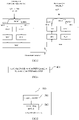
FIG. 3 , the first PDCP entity and the first RLC entity may be PDCP entities and RLC entities corresponding to the MRB of the network-side device, and the second PDCP entity and the second RLC entity may be PDCP entities and RLC entities corresponding to the DRB of the network-side device. -
Fig. 3 is an illustration that the MRB and the DRB share the same MAC entity, and in this embodiment, the MRB and the DRB may also correspond to different MAC entities, such as a first MAC entity and a second MAC entity. - Further, in this embodiment, the first PDCP entity and the first RLC entity corresponding to the MRB at the terminal side and the second PDCP entity and the second RLC entity corresponding to the DRB are also independent from each other, as shown in
FIG. 3 . - Optionally, the first PDCP entity and the second PDCP entity independently have at least one of the following functions:
encryption, integrity protection, or header compression functions. - Thus, each PDCP entity can perform a corresponding data operation to reduce interactions before protocol entities.
- In one implementation, the transmitting the QoS flow through at least one of the MRB or the DRB includes:
- the SDAP layer delivers the data packets of the QoS flow to the first PDCP entity and the second PDCP entity;
- the first PDCP entity delivers the data packet to the first RLC entity, and/or the second PDCP entity delivers the data packet to the second RLC entity.
- The SDAP layer may deliver the data packet of the QoS flow to the first PDCP entity and the second PDCP entity by respectively delivering the same data packet to the first PDCP entity and the second PDCP entity.
- The first PDCP entity may deliver the data packet to the first RLC entity, and/or the second PDCP entity may deliver the data packet to the second RLC entity, and the first PDCP entity and the second PDCP entity may determine whether to deliver the data packet to the RLC entity according to a requirement.
- In the embodiment of the present disclosure, the PDCP entity may deliver the data packet to the RLC entity after the PDCP entity performs the PDCP layer related operation on the data packet, and then deliver the data packet to the RLC entity, for example, after performing at least one of the operations of ciphering, integrity protection, and header compression, the data packet is delivered to the RLC entity, which is not limited specifically.
- Optionally, the first PDCP entity delivering the data packet to the first RLC entity, and/or the second PDCP entity delivering the data packet to the second RLC entity includes:
- the target PDCP entity starts a corresponding PDCP discard timer (PDCP discard timer) aiming at each data packet of the QoS flow;
- if the target PDCP entity allows the data transmission of the corresponding MRB or DRB, the data packet of the QoS flow is delivered to a target RLC entity;
- if the target PDCP does not allow the data transmission of the corresponding MRB or DRB, discarding the data packet when the PDCP discard timer expires;
- the target PDCP is the first PDCP entity, the target RLC is the first RLC entity, or the target PDCP is the second PDCP entity, and the target RLC is the second RLC entity.
- If the target PDCP entity allows corresponding MRB or DRB data transmission, the delivering the QoS flow data packet to the target RLC entity may be, if the first PDCP entity allows corresponding MRB data transmission, the delivering the QoS flow data packet to the first RLC entity, and if the second PDCP entity allows corresponding DRB data transmission, the delivering the QoS flow data packet to the second RLC entity. Whether the first PDCP entity allows the corresponding MRB data transmission or the second PDCP entity allows the corresponding DRB data transmission may be set according to actual requirements. For example: if the MRB is reliable enough, the DRB will not transmit, or if the MRB is unreliable, the DRB will be allowed to transmit, or both, etc.
- For example: after a QoS flow data packet reaches an SDAP layer, the SDAP layer directly delivers the same data packet to PDCP layers corresponding to MRB and DRB at the same time, the PDCP layer starts a PDCP discard timer for each data packet, if the data packet does not need to be transmitted on the MRB or the DRB, the corresponding PDCP entity does not deliver the data packet to the RLC layer, and discards the data packet after the PDCP discard timer expires; if the data packet arrives at the PDCP layer, the MRB and DRB corresponding to the PDCP layer currently allow transmission, and the data packet can be directly delivered to the RLC layer.
- In this embodiment, the space of the PDCP layer is saved by transmitting the allowed packets in time and discarding the packets that are allowed to be transmitted.
- Optionally, if the target PDCP entity allows the corresponding MRB or DRB data transmission, then delivering the QoS flow data packet to the target RLC entity includes:
- if the target PDCP entity allows the data transmission of the corresponding MRB or DRB, delivering the data packet in the QoS flow when the PDCP discard timer does not expire to the target RLC entity.
- For example: if the corresponding MRB or DRB of the PDCP entity starts to allow transmission before the PDCP discard timer expires, the PDCP entity delivers the data packet which has not expired by the PDCP discard timer to the RLC entity.
- If the target PDCP entity allows data transmission of the corresponding MRB or DRB, but there is a packet when PDCP discard timer expires, the packet may be discarded.
- In another implementation manner, the transmitting the QoS flow through at least one of the MRB or the DRB includes:
- the SDAP layer delivers the data packet of the QoS flow to the first PDCP entity which allows the MRB to perform data transmission, or delivers the data packet of the QoS flow to the second PDCP entity which allows the DRB to perform data transmission;
- the PDCP entity receiving the data packet of the QoS flow delivers the data packet to a corresponding RLC entity.
- In this implementation, the SDAP layer may be a PDCP entity that determines whether to allow MRB or DRB transmission, thereby delivering a data packet to the corresponding PDCP entity.
- For example: and when the SDAP layer receives the trigger indication and allows the MRB or the DRB to transmit the QoS flow data packet, the SDAP layer delivers the QoS flow data packet to a PDCP entity corresponding to the MRB or the DRB, and the PDCP entity delivers the data packet to a lower layer and transmits the data packet. The trigger indication may be an indication that the network-side device decides and triggers according to a decision of the network-side device, or an indication that the terminal reports to the network-side device, for example, a request for transmitting a certain MBS service on the DRB is reported.
- As an optional implementation manner, in the QoS flow of the MBS, the QoS flow mapped to the MRB is the same as the QoS flow mapped to the DRB; or The QoS flow mapped to MRB in the QoS flow of MBS is different from the QoS flow mapped to DRB wholly or partially.
- The QoS flow mapped to MRB and the QoS flow mapped to DRB in the QoS flow of MBS may be the same, where the QoS flow mapped to MRB and the QoS flow mapped to DRB of a single terminal are completely the same, for example, QoS flow of QFI =1 and QoS flow of QFI =2 are mapped to MRB, and at the same time, these two QoS flows are mapped to DRB 1 of terminal 1.
- The QoS flow mapped to MRB and the QoS flow mapped to DRB in the QoS flow of MBS may be totally or partially different, but not totally the same QoS flow exists for the QoS flow mapped to MRB and DRB, for example: the QoS flow mapped to MRB and to single terminal DRB may be partly different, e.g. QoS flow of QFI =1 is mapped to MRB, QoS flow of QFI =1 and QoS flow of QFI =2 is mapped to DRB 1 of terminal 1. Alternatively, there may not be the same QoS flow mapped to MRB and DRB, for example: QoS flow as QFI =1 is mapped to MRB, and QoS flow as QFI =2 is mapped to DRB 1 of terminal 1.
- Optionally, when there is a QoS flow associated with the mapping to the MRB and the DRB, the duplication detection and the repeated discard of the data packet of the QoS flow may be performed by the network-side device, or may be performed on the terminal without limitation.
- As an optional embodiment, an interface is established between the first PDCP entity and the second PDCP entity, where the interface is configured to transfer information such that the first PDCP entity and the second PDCP entity add the same PDCP SN to the same data packet.
- The interface establishment between the first PDCP entity and the second PDCP entity may be performed after
step 201 is performed, or may be performed beforestep 201 is performed, or may be performed duringstep 201 is performed, which is not limited herein. - The interface is configured to transmit information so that the first PDCP entity and the second PDCP entity add the same PDCP SN to the same data packet, where the first PDCP entity and the second PDCP entity perform information transmission through the interface, so that if the first PDCP entity and the second PDCP entity receive the same data packet, the same data packet is set as the same PDCP SN to implement duplicate detection of the data packet.
- In this embodiment, since the interface is established, the first PDCP entity and the second PDCP entity may add the same PDCP SN to the same data packet to implement duplicate packet detection.
- Optionally, the method further includes:
and the PDCP entity which is sending the data packet of the QoS flow of the MBS in the first PDCP entity and the second PDCP entity determines the PDCP SN of the next data packet delivered from the SDAP layer and transmits the PDCP SN to the other PDCP entity, and the other PDCP entity distributes the PDCP SN to the next data packet delivered by the SDAP layer. - The PDCP entity that is sending the data packet of the QoS flow of the MBS may be the PDCP entity that is currently sending the data packet of the QoS flow of the MBS, but the next data packet may be sent by the PDCP entity and another PDCP entity, or by another PDCP entity, so that the PDCP SN of the next data packet may be determined to be transferred to another PDCP entity through the interface.
- The next data packet delivered from the SDAP layer may be a data packet simultaneously delivered by the SDAP layer to the first PDCP entity and the second PDCP entity, or a data packet delivered by the SDAP layer to the first PDCP entity or the second PDCP entity.
- In this embodiment, the PDCP SN of the next packet is transferred through the interface, so that the two PDCP entities can maintain the same PDCP SN to achieve the continuity of the PDCP SNs.
- For example: when receiving the trigger indication, the SDAP layer delivers the QoS flow data packet to the PDCP entity corresponding to the MRB or DRB allowed to transmit, the PDCP layers of the MRB and DRB at the transmitting end can establish connection, the PDCP entity transmitting expects that two PDCP simultaneously receive the PDCP SN of the data packet from the SDAP layer to transmit to the PDCP entity corresponding to the MRB or DRB about to start transmitting the QoS flow data, and the two subsequent PDCP entities can maintain the same PDCP SN.
- In the embodiment of the disclosure, QoS flow of MBS is mapped to MRB and Data Radio Bearer (DRB); transmitting the QoS flow through at least one of the MRB or the DRB. Because the QoS flow of the MBS is mapped to the MRB and the Data Radio Bearer (DRB), the reliability of the MBS can be improved.
- Referring to
FIG. 4, FIG. 4 is a flowchart of another data flow transmission method provided in an embodiment of the present disclosure, where the method is applied to a terminal, and as shown inFIG. 4 , the method includes the following steps:
401. receiving QoS flow of MBS through at least one of MRB and DRB; and the QoS flow of the MBS has a mapping relation with the MRB and the DRB respectively. - The mapping relationship between the QoS flow of the MBS and the MRB and the DRB may be determined according to configuration information sent by a network-side device, for example: and receiving the QoS flow and MRB mapping configured by the network-side device, the DRB mapping relation and the related parameter configuration. Of course, the mapping relationship may also be reported to the network-side device by the terminal, which is not limited to this.
- Optionally, the first Packet Data Convergence Protocol (PDCP) entity and the first Radio Link Control (RLC) entity corresponding to the MRB are independent from the second PDCP entity and the second RLC entity corresponding to the DRB.
- Optionally, the first PDCP entity and the second PDCP entity independently have at least one of the following functions:
- decryption, de-integrity protection, or de-header compression functions.
- Optionally, the MRB and the DRB share the same MAC entity; or
- The MRB and the DRB correspond to different MAC entities.
- Optionally, the receiving the QoS flow of the MBS through at least one of the MRB or the DRB includes:
- the first RLC entity transmits the data packet of the QoS flow of the MBS received by the MAC layer to the first PDCP entity, and the first PDCP entity uploads the data packet to the SDAP layer; and/or
- the second RLC entity transmits the data packet of the QoS flow of the MBS received by the MAC layer to the second PDCP entity, and the second PDCP entity uploads the data packet to the SDAP layer.
- Optionally, the QoS flow mapped to the MRB in the QoS flow of the MBS is the same as the QoS flow mapped to the DRB; or
- The QoS flow mapped to MRB in the QoS flow of MBS is different from the QoS flow mapped to DRB wholly or partially.
- Optionally, the method further includes:
the first PDCP entity and/or the second PDCP entity deliver data packets to an upper layer, and duplication detection is carried out by the upper layer; or - An interface is established between the first PDCP entity and the second PDCP entity, the first PDCP entity transmits a PDCP Protocol Data Unit (PDU) to the second PDCP entity through the interface, the second PDCP entity carries out duplication detection, and the PDCP PDU is a PDU containing a data packet of the QoS flow of the MBS; or
- And an interface is established between the first PDCP entity and the second PDCP entity, the second PDCP entity transmits PDCP PDUs to the first PDCP entity through the interface, the first PDCP entity carries out duplication detection, and the PDCP PDUs are PDUs of data packets containing the QoS flow of the MBS.
- The higher layer may be an IP layer or other higher layers, and after receiving the data packet delivered by the first PDCP entity and/or the second PDCP entity, the higher layer may perform duplicate detection according to the content of the data packet, and may also perform duplicate discarding. For example: the terminal receives the downlink data sent by MRB and DRB independently, the PDCP layer directly submits to the higher layer after processing, and the higher layer (such as IP layer) realizes duplication detection and discarding.
- An interface is established between the first PDCP entity and the second PDCP entity, the first PDCP entity transfers PDCP protocol data units PDUs to the second PDCP entity through the interface, and the second PDCP entity performs duplicate detection, where the PDCP PDUs are PDUs of data packets including the QoS flow of the MBS, and may be the second PDCP entity serving as a primary PDCP entity, the first PDCP entity serving as an auxiliary PDCP entity, and the auxiliary PDCP entity transfers PDCP PDUs to the primary PDCP entity, and the primary PDCP entity performs duplicate detection.
- An interface is established between the first PDCP entity and the second PDCP entity, the second PDCP entity transfers PDCP PDUs to the first PDCP entity through the interface, and the first PDCP entity performs duplicate detection, where the PDCP PDUs are PDUs of a data packet containing the QoS flow of the MBS, and the first PDCP entity may be used as a main PDCP entity, the second PDCP entity as an auxiliary PDCP entity, and the auxiliary PDCP entity transfers PDCP PDUs to the main PDCP entity, and the main PDCP entity performs duplicate detection.
- For example: the terminal establishes connection between MRB and receiving PDCP layer of DRB, one PDCP entity is used as a main entity, namely, the MRB or PDCP of the DRB is used as the main PDCP entity, the other PDCP entity is used as an auxiliary PDCP entity, the auxiliary PDCP entity transmits the PDCP PDUs which are subjected to decryption, integrity protection and header decompression (the three processes are optional according to the configuration of network-side device) to the main PDCP entity, and the main PDCP entity carries out duplication detection and discarding operation.
- Optionally, the transferring the PDCP PDU to the second PDCP entity by the first PDCP entity through an interface includes: the first PDCP entity directly transmits the received PDCP PDUs to the second PDCP entity through an interface without sorting;
the second PDCP entity transferring PDCP PDUs to the first PDCP entity through an interface, including: the second PDCP entity directly transfers the received PDCP PDUs to the first PDCP entity through an interface without sorting. - Since the data can be directly transmitted through the interface without sorting, the efficiency can be improved. Further, in this embodiment, the first PDCP entity and the second PDCP entity of the network-side device may maintain the same PDCP SN for the same data, that is, add the same PDCP SN in the PDCP layers corresponding to the MRB and the DRB for the same QoS flow data packet.
- Optionally, the performing, by the first PDCP entity, duplicate detection includes:
the first PDCP entity processes the received PDCP PDUs transferred by the second PDCP entity through the interface and the PDCP PDUs from the first RLC entity to carry out duplication detection, and if the PDCP SNs contained in the PDCP PDUs are already received in the first PDCP entity, the PDCP PDUs are discarded. - The first PDCP entity may detect duplication of the received PDCP PDUs transferred by the second PDCP entity through the interface with the PDCP PDUs from the first RLC entity by detecting whether there are duplicate PDCP PDUs in the PDCP PDUs received by the second PDCP entity and the PDCP PDUs received by the first RLC entity, and discard the PDCP PDUs if the PDCP SNs included in the PDCP PDUs have been received in the first PDCP entity.
- Similarly, the performing of duplicate detection by the second PDCP entity may include:
the second PDCP entity processes the received PDCP PDUs transferred by the first PDCP entity through the interface and the PDCP PDUs from the second RLC entity together for duplication detection, and if the PDCP SNs contained in the PDCP PDUs are already received in the first PDCP entity, the PDCP PDUs are discarded. - It should be noted that, this embodiment is used as an implementation of the terminal corresponding to the embodiment shown in
FIG. 2 , and specific implementations thereof may refer to relevant descriptions of the embodiment shown inFIG. 2 , so that, in order to avoid repeated descriptions, this embodiment is not described again, and the same beneficial effects may also be achieved. - The following exemplifies data flow transmission provided by the embodiment of the present disclosure, with a network-side device as a base station:
example 1:
in this embodiment, the QoS flow of the MBS service is transmitted through the MRB and the DRB at the same time, which may specifically be as follows:
a base station side: - step 1: the base station configures mapping between QoS flow (QFI = x) of MBS service and MRB 1, and mapping between QoS flow and DRB 1 of UE1, and configures layer 2 and layer 1 parameters of DRB1 of MRB1 and UE1 respectively. The MRB 1 performs multicast transmission (using a multicast channel) on a group of terminals receiving the MBS service, and the DRB1 performs unicast transmission (using a unicast channel) on the UE 1.
- Step 2: the SDAP layer of the base station maps QoS flow (QFI = x) of MBS service to the PDCP layers of MRB 1 and DRB 1 of UE1, can deliver data packets of QoS flow to the PDCP layers of MRB 1 and DRB 1 at the same time, and can deliver the data packets of QoS flow to the lower layer by the PDCP layers of MRB1 and/or DRB1, or can deliver the data packets of QoS flow to the PDCP layers of MRB1 or DRB1, and the data packets of MRB 1 or DRB 1 are delivered to the lower layer by the PDCP layers of MRB 1 or DRB 1, and are sent to the terminal at the air interface.
- Terminal side (UE 1):
- Step 1: receiving base station side configured QoS flow (QFI = x) and MRB1 mapping, and DRB 1 mapping relation and related parameter configuration of UE 1.
- Step 2: data packets of QoS flow (QFI = x) are received from the protocol stacks corresponding to MRB1 and DRB1, respectively.
- Step 3: the receiving PDCP entity performs duplicate detection and duplicate deletion on the data received from the MRB1 and the DRB1, where the manner of duplicate detection and duplicate deletion may refer to the related manner of the embodiment shown in
FIG. 4 , and is not described herein again. - Example 2:
in this embodiment, the QoS flow of the MBS service is changed from transmission through MRB to transmission through DRB, which may specifically be as follows:
a base station side: - step 1: the base station configures mapping between QoS flow (QFI = x) of MBS service and MRB 1, and mapping between QoS flow and DRB 1 of UE1, and configures layer 2 and layer 1 parameters of DRB1 of MRB1 and UE1 respectively. The MRB 1 performs multicast transmission (using a multicast channel) on a group of terminals receiving the MBS service, and the DRB1 performs unicast transmission (using a unicast channel) on the UE 1. The two sets of configurations can be performed simultaneously or separately, for example, mapping of QoS flow (QFI = x) to DRB 1 is configured only before the transmission mode needs to be changed.
- Step 2: the SDAP layer of the base station maps QoS flow (QFI = x) of MBS service to MRB1 for transmission, and delivers data packets to a PDCP entity of MRB1 for transmission. If the QoS flow of the MBS service is determined not to need to be transmitted by the multicast mode, the QoS flow is changed to be transmitted only by the DRB1 of the UE1 (if other UEs can also receive the MBS by the unicast, the operation process is the same as that of the UE 1). The base station transmits the data packet of the MBS service QoS flow through the channel of the DRB 1. The specific procedure of delivering the data packet from the SDAP layer to the PDCP layer can be implemented as the embodiment shown in
FIG. 2 . For example: if the mode of delivering the data packets to the PDCP entities of the MRB 1 and the DRB 1 is adopted, before the MRB 1 or the DRB 1 is released, the SDAP delivers the arriving MBS service data packets to the two PDCP entities simultaneously; if the mode of delivering the data packets to the PDCP entity of the MRB1 or the DRB1 is adopted, the SDAP layer delivers the QoS flow data packets of the MBS service to the PDCP layer entity of the MRB 1 before the transmission mode is changed, and delivers the QoS flow data packets of the MBS service to the PDCP layer entity of the DRB1 after the change. - Terminal side (UE 1):
- Step 1: receiving base station side configured QoS flow (QFI = x) and MRB1 mapping, and DRB 1 mapping relation and related parameter configuration of UE 1.
- Step 2: and receiving data of the MBS service from a protocol stack corresponding to the MRB1 and a lower layer configuration. When the QoS flow of the MBS service is changed from multi-cast transmission to unicast transmission, a protocol stack corresponding to the DRB 1 and a lower layer configuration are used for receiving a data packet of the QoS flow.
- Step 3: during a change from multicast to unicast transmission, portions of the data packets may be transmitted from both MRB 1 and DRB 1. The receiving PDCP entity performs duplicate detection and duplicate deletion on the data received from the MRB 1 and the DRB 1, where the manner of duplicate detection and duplicate deletion may refer to the related manner of the embodiment shown in
FIG. 4 , and details are not repeated here. - Example 3:
in this embodiment, the QoS flow of the MBS service is changed from transmission through the DRB to transmission through the MRB, which may specifically be as follows:
a base station side: - step 1: the base station configures mapping between QoS flow (QFI = x) of MBS service and MRB 1, and mapping between QoS flow and DRB 1 of UE1, and configures layer 2 and layer 1 parameters of DRB1 of MRB1 and UE1 respectively. The MRB 1 performs multicast transmission (using a multicast channel) on a group of terminals receiving the MBS service, and the DRB1 performs unicast transmission (using a unicast channel) on the UE 1. The two sets of configurations can be performed simultaneously or separately, for example, mapping of QoS flow (QFI = x) to MRB 1 is configured only before the transmission mode needs to be changed.
- Step 2: the SDAP layer of the base station maps QoS flow (QFI = x) of MBS service to DRB1 for transmission, and delivers data packets to a PDCP entity of DRB1 for transmission. If the QoS flow of the MBS service is determined not to be transmitted in a unicast mode, but is only transmitted through the MRB 1, the base station transmits the data packet of the MBS service QoS flow through the channel of the MRB 1. The specific procedure of delivering the data packet from the SDAP layer to the PDCP layer can be implemented as the embodiment shown in
FIG. 2 . For example: if the mode of delivering the data packets to the PDCP entities of the MRB 1 and the DRB 1 is adopted, before the MRB 1 or the DRB 1 is released, the SDAP delivers the arriving MBS service data packets to the two PDCP entities simultaneously; if the mode of delivering the data packets to the PDCP entity of the MRB1 or the DRB1 is adopted, the SDAP layer delivers the QoS flow data packets of the MBS service to the PDCP layer entity of the DRB 1 before the transmission mode is changed, and delivers the QoS flow data packets of the MBS service to the PDCP layer entity of the MRB 1 after the change. - Terminal side (UE 1):
- Step 1: receiving base station side configured QoS flow (QFI = x) and MRB1 mapping, and DRB 1 mapping relation and related parameter configuration of UE 1.
- Step 2: and receiving data of the MBS service from a protocol stack corresponding to the DRB1 and low-layer configuration. When the QoS flow of the MBS service is changed from unicast transmission to multicast transmission, a protocol stack corresponding to the MRB 1 and low-layer configuration are used for receiving a data packet of the QoS flow.
- Step 3: during a change from unicast transmission to multicast transmission, portions of the data packets may be transmitted from MRB 1 and DRB 1 simultaneously. The receiving PDCP entity performs duplicate detection and duplicate deletion on the data received from the MRB 1 and the DRB 1, where the manner of duplicate detection and duplicate deletion may refer to the related manner of the embodiment shown in
FIG. 4 , and details are not repeated here. - Referring to
FIG. 5, FIG. 5 is a structural diagram of a network-side device according to an embodiment of the present disclosure, and as shown inFIG. 5 , the network-side device 500 includes: - a
mapping module 501, configured to map a QoS flow of a Multicast and Broadcast Services (MBS) to a MBS Radio Bearer (MRB) and a Data Radio Bearer (DRB); - a
transmitting module 502, configured to transmit the QoS flow through at least one of the MRB or the DRB. - Optionally, mapping the QoS flow of the MBS to the MRB and the DRB includes:
and mapping the QoS flow of the MBS to an MRB and a DRB through an SDAP layer, where a first PDCP entity and a first RLC entity corresponding to the MRB are independent from a second PDCP entity and a second RLC entity corresponding to the DRB. - Optionally, the first PDCP entity and the second PDCP entity independently have at least one of the following functions:
performs encryption, integrity protection, or header compression functions. - Optionally, the MRB and the DRB share the same MAC entity; or
- The MRB and the DRB correspond to different MAC entities.
- Optionally, the transmitting
module 502 is configured to: - the SDAP layer delivers the data packets of the QoS flow to the first PDCP entity and the second PDCP entity;
- the first PDCP entity delivers the data packet to the first RLC entity, and/or the second PDCP entity delivers the data packet to the second RLC entity.
- Optionally, the first PDCP entity delivering the data packet to the first RLC entity, and/or the second PDCP entity delivering the data packet to the second RLC entity includes:
- the target PDCP entity starts a corresponding PDCP discard timer aiming at each data packet of the QoS flow;
- if the target PDCP entity allows the data transmission of the corresponding MRB or DRB, the data packet of the QoS flow is delivered to a target RLC entity;
- if the target PDCP does not allow the data transmission of the corresponding MRB or DRB, discarding the data packet of which the PDCP discard timer expires;
- the target PDCP is the first PDCP entity, the target RLC is the first RLC entity, or the target PDCP is the second PDCP entity, and the target RLC is the second RLC entity.
- Optionally, if the target PDCP entity allows the corresponding MRB or DRB data transmission, then delivering the QoS flow data packet to the target RLC entity includes: if the target PDCP entity allows the data transmission of the corresponding MRB or DRB, delivering the data packet in the QoS flow when the PDCP discard timer does not expire to the target RLC entity.
- Optionally, the transmitting
module 502 is configured to: - the SDAP layer delivers the data packet of the QoS flow to the first PDCP entity which allows the MRB to perform data transmission, or delivers the data packet of the QoS flow to the second PDCP entity which allows the DRB to perform data transmission;
- the PDCP entity receiving the data packet of the QoS flow delivers the data packet to a corresponding RLC entity.
- Optionally, the QoS flow mapped to the MRB in the QoS flow of the MBS is the same as the QoS flow mapped to the DRB; or
The QoS flow mapped to MRB in the QoS flow of MBS is different from the QoS flow mapped to DRB wholly or partially. - Optionally, an interface is established between the first PDCP entity and the second PDCP entity, where the interface is configured to transfer information so that the first PDCP entity and the second PDCP entity add the same PDCP SN to the same data packet.
- Optionally, as shown in
FIG. 6 , the network-side device further includes:
a determiningmodule 503, configured to determine a PDCP SN of a next data packet delivered from the SDAP layer by a PDCP entity that is sending a data packet of the QoS flow of the MBS in the first PDCP entity and the second PDCP entity, and transmit the PDCP SN to another PDCP entity, where the another PDCP entity allocates the PDCP SN to the next data packet delivered by the SDAP layer. - It should be noted that, in this embodiment, the network-
side device 500 may be a network-side device in any implementation manner in the method embodiment in the present disclosure, and any implementation manner of the network-side device in the method embodiment in the present disclosure may be implemented by the network-side device 500 in this embodiment to achieve the same beneficial effect, which is not described herein again. - Referring to
FIG. 7, FIG. 7 is a structural diagram of a terminal according to an embodiment of the present disclosure, and as shown inFIG. 7 , a terminal 700 includes: a receivingmodule 701, configured to receive a QoS flow of a Multicast and Broadcast Services (MBS) through at least one of a MBS Radio Bearer (MRB) and a Data Radio Bearer (DRB); and the QoS flow of the MBS has a mapping relation with the MRB and the DRB respectively. - Optionally, the first Packet Data Convergence Protocol (PDCP) entity and the first Radio Link Control (RLC) entity corresponding to the MRB are independent from the second PDCP entity and the second RLC entity corresponding to the DRB.
- Optionally, the first PDCP entity and the second PDCP entity independently have at least one of the following functions:
perform decryption, de-integrity protection, or de-header compression functions. - Optionally, the MRB and the DRB share the same MAC entity; or
- The MRB and the DRB correspond to different MAC entities.
- Optionally, the receiving
module 701 is configured to:
the first RLC entity transmits the data packet of the QoS flow of the MBS received by the MAC layer to the first PDCP entity, and the first PDCP entity uploads the data packet to a Service Data Adaptation Protocol (SDAP) layer; and/or - And the second RLC entity transmits the data packet of the QoS flow of the MBS received by the MAC layer to the second PDCP entity, and the second PDCP entity uploads the data packet to the SDAP layer.
- Optionally, the QoS flow mapped to the MRB in the QoS flow of the MBS is the same as the QoS flow mapped to the DRB; or
The QoS flow mapped to MRB in the QoS flow of MBS is different from the QoS flow mapped to DRB wholly or partially. - Optionally, as shown in
FIG. 8 , the terminal 700 further includes adetection module 702, configured to: - the first PDCP entity and/or the second PDCP entity deliver data packets to an upper layer, and duplication detection is carried out by the upper layer; or
- An interface is established between the first PDCP entity and the second PDCP entity, the first PDCP entity transmits PDCP PDUs to the second PDCP entity through the interface, the second PDCP entity carries out duplication detection, and the PDCP PDUs are PDUs of data packets containing QoS flow of the MBS; or
- And an interface is established between the first PDCP entity and the second PDCP entity, the second PDCP entity transmits PDCP PDUs to the first PDCP entity through the interface, the first PDCP entity carries out duplication detection, and the PDCP PDUs are PDUs of data packets containing the QoS flow of the MBS.
- Optionally, the transferring the PDCP PDU to the second PDCP entity by the first PDCP entity through an interface includes: the first PDCP entity directly transmits the received PDCP PDUs to the second PDCP entity through an interface without sorting;
- the second PDCP entity transferring PDCP PDUs to the first PDCP entity through an interface, including: the second PDCP entity directly transfers the received PDCP PDUs to the first PDCP entity through an interface without sorting.
- Optionally, the performing, by the first PDCP entity, duplicate detection includes:
- the first PDCP entity processes the received PDCP PDUs transferred by the second PDCP entity through the interface and the PDCP PDUs from the first RLC entity together for duplication detection, and if the PDCP SNs contained in the PDCP PDUs are already received in the first PDCP entity, the PDCP PDUs are discarded;
- the second PDCP entity performing duplicate detection, including:
the second PDCP entity processes the received PDCP PDUs transferred by the first PDCP entity through the interface and the PDCP PDUs from the second RLC entity together for duplication detection, and if the PDCP SNs contained in the PDCP PDUs are already received in the first PDCP entity, the PDCP PDUs are discarded. - It should be noted that, in this embodiment, the terminal 700 may be a terminal in any implementation manner in the method embodiment in the present disclosure, and any implementation manner of the terminal in the method embodiment in the present disclosure may be implemented by the terminal 700 in this embodiment to achieve the same beneficial effect, which is not described herein again.
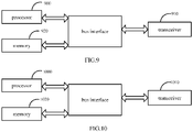
- Referring to
FIG. 9, FIG. 9 is a structural diagram of another network-side device provided in an embodiment of the present disclosure, and as shown inFIG. 9 , the network-side device includes: a transceiver 910, amemory 920, aprocessor 900, and a program stored on thememory 920 and executable on the processor, where: - the transceiver 910 or the
processor 900 is configured to map a QoS flow of a Multicast and Broadcast Services (MBS) to a MBS Radio Bearer (MRB) and a Data Radio Bearer (DRB); - the transceiver 910 is configured to transmit the QoS flow through at least one of the MRB or the DRB.
- Among other things, the transceiver 910 may be used to receive and transmit data under the control of the
processor 900. - In
FIG. 9 , the bus architecture may include any number of interconnected buses and bridges, with various circuits representing one or more processors, inparticular processor 900, and a memory, inparticular memory 920. The bus architecture may also link together various other circuits such as peripherals, voltage regulators, power management circuits, and the like, which are well known in the art, and therefore, will not be described any further herein. The bus interface provides an interface. The transceiver 910 may be a plurality of elements including a transmitter and a receiver that provide a means for communicating with various other apparatus over a transmission medium. - The
processor 900 is responsible for managing the bus architecture and general processing, and thememory 920 may store data used by theprocessor 900 in performing operations. - It should be noted that the
memory 920 is not limited to be only on the network-side device, and thememory 920 and theprocessor 900 may be separated and located in different geographical locations. - Optionally, mapping the QoS flow of the MBS to the MRB and the DRB includes: and mapping the QoS flow of the MBS to an MRB and a DRB through an SDAP layer, where a first PDCP entity and a first RLC entity corresponding to the MRB are independent from a second PDCP entity and a second RLC entity corresponding to the DRB.
- Optionally, the first PDCP entity and the second PDCP entity independently have at least one of the following functions:
performs encryption, integrity protection, or header compression functions. - Optionally, the MRB and the DRB share the same MAC entity; or
- The MRB and the DRB correspond to different MAC entities.
- Optionally, the transmitting the QoS flow through at least one of the MRB or the DRB includes:
- the SDAP layer delivers the data packets of the QoS flow to the first PDCP entity and the second PDCP entity;
- the first PDCP entity delivers the data packet to the first RLC entity, and/or the second PDCP entity delivers the data packet to the second RLC entity.
- Optionally, the first PDCP entity delivering the data packet to the first RLC entity, and/or the second PDCP entity delivering the data packet to the second RLC entity includes:
- the target PDCP entity starts a corresponding PDCP discard timer aiming at each data packet of the QoS flow;
- if the target PDCP entity allows the data transmission of the corresponding MRB or DRB, the data packet of the QoS flow is delivered to a target RLC entity;
- if the target PDCP does not allow the data transmission of the corresponding MRB or DRB, discarding the data packet of which the PDCP discard timer expires;
- where, the target PDCP is the first PDCP entity, the target RLC is the first RLC entity, or the target PDCP is the second PDCP entity, and the target RLC is the second RLC entity.
- Optionally, if the target PDCP entity allows the corresponding MRB or DRB data transmission, then delivering the QoS flow data packet to the target RLC entity includes:
if the target PDCP entity allows the data transmission of the corresponding MRB or DRB, delivering the data packet in the QoS flow when the PDCP discard timer does not expire to the target RLC entity. - Optionally, the transmitting the QoS flow through at least one of the MRB or the DRB includes:
- the SDAP layer delivers the data packet of the QoS flow to the first PDCP entity which allows the MRB to perform data transmission, or delivers the data packet of the QoS flow to the second PDCP entity which allows the DRB to perform data transmission;
- the PDCP entity receiving the data packet of the QoS flow delivers the data packet to a corresponding RLC entity.
- Optionally, the QoS flow mapped to the MRB in the QoS flow of the MBS is the same as the QoS flow mapped to the DRB; or
- The QoS flow mapped to MRB in the QoS flow of MBS is different from the QoS flow mapped to DRB wholly or partially.
- Optionally, an interface is established between the first PDCP entity and the second PDCP entity, where the interface is configured to transfer information, so that the first PDCP entity and the second PDCP entity add the same PDCP Sequence Number (SN) to the same data packet.
- Optionally, the transceiver 910 or the
processor 900 is further configured to:
and the PDCP entity which is sending the data packet of the QoS flow of the MBS in the first PDCP entity and the second PDCP entity determines the PDCP SN of the next data packet delivered from the SDAP layer and transmits the PDCP SN to the other PDCP entity, and the other PDCP entity distributes the PDCP SN to the next data packet delivered by the SDAP layer. - It should be noted that, in this embodiment, the network-side device may be a network-side device in any implementation manner in the method embodiment in the present disclosure, and any implementation manner of the network-side device in the method embodiment in the present disclosure may be implemented by the network-side device in this embodiment to achieve the same beneficial effect, which is not described herein again.
- Referring to
FIG. 10, FIG. 10 is a structural diagram of another terminal provided in the embodiment of the present disclosure, and as shown inFIG. 10 , the terminal includes: atransceiver 1010, amemory 1020, aprocessor 1000, and a program stored on thememory 1020 and executable on theprocessor 1000, where:
thetransceiver 1010 is configured to receive a QoS flow of a Multicast and Broadcast Services (MBS) through at least one of a MBS Radio Bearer (MRB) and a Data Radio Bearer (DRB); and the QoS flow of the MBS has a mapping relation with the MRB and the DRB respectively. - Among other things, the
transceiver 1010 may be used to receive and transmit data under the control of theprocessor 1000. - In
FIG. 10 , the bus architecture may include any number of interconnected buses and bridges, with various circuits being linked together, in particular, one or more processors, represented byprocessor 1000, and a memory, represented bymemory 1020. The bus architecture may also link together various other circuits such as peripherals, voltage regulators, power management circuits, and the like, which are well known in the art, and therefore, will not be described any further herein. The bus interface provides an interface. Thetransceiver 1010 may be a number of elements including a transmitter and a receiver that provide a means for communicating with various other apparatus over a transmission medium. - The
processor 1000 is responsible for managing the bus architecture and general processing, and thememory 1020 may store data used by theprocessor 1000 in performing operations. - It should be noted that the
memory 1020 is not limited to being on the terminal, and thememory 1020 and theprocessor 1000 may be separated in different geographical locations. - Optionally, the first Packet Data Convergence Protocol (PDCP) entity and the first Radio Link Control (RLC) entity corresponding to the MRB are independent from the second PDCP entity and the second RLC entity corresponding to the DRB.
- Optionally, the first PDCP entity and the second PDCP entity independently have at least one of the following functions:
perform decryption, de-integrity protection, or de-header compression functions. - Optionally, the MRB and the DRB share the same MAC entity; or
- The MRB and the DRB correspond to different MAC entities.
- Optionally, the receiving the QoS flow of the MBS through at least one of the MRB or the DRB includes:
the first RLC entity transmits the data packet of the QoS flow of the MBS received by the MAC layer to the first PDCP entity, and the first PDCP entity uploads the data packet to a Service Data Adaptation Protocol (SDAP) layer; and/or - And the second RLC entity transmits the data packet of the QoS flow of the MBS received by the MAC layer to the second PDCP entity, and the second PDCP entity uploads the data packet to the SDAP layer.
- Optionally, the QoS flow mapped to the MRB in the QoS flow of the MBS is the same as the QoS flow mapped to the DRB; or
- The QoS flow mapped to MRB in the QoS flow of MBS is different from the QoS flow mapped to DRB wholly or partially.
- Optionally, the
transceiver 1010 or theprocessor 1000 is further configured to:
the first PDCP entity and/or the second PDCP entity deliver data packets to an upper layer, and duplication detection is carried out by the upper layer; or - An interface is established between the first PDCP entity and the second PDCP entity, the first PDCP entity transmits a PDCP Protocol Data Unit (PDU) to the second PDCP entity through the interface, the second PDCP entity carries out duplication detection, and the PDCP PDU is a PDU containing a data packet of the QoS flow of the MBS; or
- And an interface is established between the first PDCP entity and the second PDCP entity, the second PDCP entity transmits PDCP PDUs to the first PDCP entity through the interface, the first PDCP entity carries out duplication detection, and the PDCP PDUs are PDUs of data packets containing the QoS flow of the MBS.
- Optionally, the transferring the PDCP PDU to the second PDCP entity by the first PDCP entity through an interface includes: the first PDCP entity directly transmits the received PDCP PDUs to the second PDCP entity through an interface without sorting;
the second PDCP entity transferring PDCP PDUs to the first PDCP entity through an interface, including: the second PDCP entity directly transfers the received PDCP PDUs to the first PDCP entity through an interface without sorting. - Optionally, the performing, by the first PDCP entity, duplicate detection includes:
- the first PDCP entity processes the received PDCP PDUs transferred by the second PDCP entity through the interface and the PDCP PDUs from the first RLC entity together for duplication detection, and if the PDCP SNs contained in the PDCP PDUs are already received in the first PDCP entity, the PDCP PDUs are discarded;
- the second PDCP entity performing duplicate detection, including:
the second PDCP entity processes the received PDCP PDUs transferred by the first PDCP entity through the interface and the PDCP PDUs from the second RLC entity together for duplication detection, and if the PDCP SNs contained in the PDCP PDUs are already received in the first PDCP entity, the PDCP PDUs are discarded. - It should be noted that, the terminal in this embodiment may be a terminal in any implementation manner in the method embodiment in the embodiment of the present disclosure, and any implementation manner of the terminal in the method embodiment in the embodiment of the present disclosure may be implemented by the terminal in this embodiment to achieve the same beneficial effect, and details are not described here again.
- The disclosed embodiment also provides a computer readable storage medium, on which a computer program is stored, where the program is executed by a processor to implement the steps in the data flow transmission method on the network-side device side provided by the disclosed embodiment, or the program is executed by a processor to implement the steps in the data flow transmission method on the terminal side provided by the disclosed embodiment.
- In the several embodiments provided in the present application, it should be understood that the disclosed method and apparatus may be implemented in other manners. For example, the above-described apparatus embodiments are merely illustrative, and for example, the division of the units is only one type of logical functional division, and other divisions may be realized in practice, for example, multiple units or components may be combined or integrated into another system, or some features may be omitted, or not executed. In addition, the shown or discussed mutual coupling or direct coupling or communication connection may be an indirect coupling or communication connection through some interfaces, devices or units, and may be in an electrical, mechanical or other form.
- In addition, functional units in the embodiments of the present disclosure may be integrated into one processing unit, or each unit may be separately and physically included, or two or more units may be integrated into one unit. The integrated unit may be implemented in the form of hardware, or in the form of hardware plus a software functional unit.
- The integrated unit implemented in the form of a software functional unit may be stored in a computer-readable storage medium. The software functional unit is stored in a storage medium and includes several instructions to enable a computer device (which may be a personal computer, a server, or a network-side device, etc.) to execute some steps of the method for processing the information data block according to various embodiments of the present disclosure. And the aforementioned storage medium includes: a U-disk, a portable hard disk, a Read-Only Memory (ROM), a Random Access Memory (RAM), a magnetic disk or an optical disk, and other media capable of storing program codes.
- It should be noted that the division of each module is only a logical division, and all or part of the actual implementation may be integrated into one physical entity or may be physically separated. And these modules can all be implemented in the form of software invoked by a processing element; or can be implemented in the form of hardware; and part of the modules can be realized in the form of calling software by the processing element, and part of the modules can be realized in the form of hardware. For example, the determining module may be a processing element separately set up, or may be integrated into a chip of the apparatus, or may be stored in a memory of the apparatus in the form of program code, and a processing element of the apparatus calls and executes the function of the determining module. The other modules are implemented similarly. In addition, all or part of the modules can be integrated together or can be independently realized. The processing element described herein may be an integrated circuit having signal processing capabilities. In implementation, each step of the above method or each module above may be implemented by an integrated logic circuit of hardware in a processor element or an instruction in the form of software.
- For example, the various modules, units, sub-units or sub-modules may be one or more integrated circuits configured to implement the above methods, such as: one or more Application Specific Integrated Circuits (ASICs), or one or more microprocessors (DSPs), or one or more Field Programmable Gate Arrays (FPGAs), among others. For another example, when some of the above modules are implemented in the form of a Processing element scheduler code, the Processing element may be a general-purpose processor, such as a Central Processing Unit (CPU) or other processor that can call the program code. As another example, these modules may be integrated together and implemented in the form of a system-on-a-chip (SOC).
- The terms "first," "second," and the like in the description and in the claims of the present disclosure are used for distinguishing between similar elements and not necessarily for describing a particular sequential or chronological order. It is to be understood that the data so used may be interchanged under appropriate circumstances such that embodiments of the disclosure described herein may be implemented, for example, in sequences other than those illustrated or described herein. Moreover, the terms "includes," "including," and "having," and any variations thereof, are intended to cover a non-exclusive inclusion, such that a process, method, system, article, or apparatus that includes a list of steps or elements is not necessarily limited to those steps or elements expressly listed, but may include other steps or elements not expressly listed or inherent to such process, method, article, or apparatus. Further, the use of "and/or" in the specification and claims means that at least one of the connected objects, such as a and/or B and/or C, means that 7 cases are included that include a alone, B alone, C alone, and both a and B, B and C, a and C, and A, B and C. Similarly, the use of "at least one of A and B" in the specification and claims is to be understood as "A alone, B alone, or both A and B present".
- While the foregoing is directed to alternative embodiments of the present disclosure, it will be appreciated by those skilled in the art that various changes and modifications may be made therein without departing from the principles of the disclosure, and it is intended that such changes and modifications be covered by the scope of the disclosure.
Claims (33)
- A data flow transmission method, applied to network-side device and comprising:mapping Quality of Service (QoS) flows of a Multicast and Broadcast Services (MBS) to an MBS Radio Bearer (MRB) and a Data Radio Bearer (DRB);transmitting the QoS flows through at least one of the MRB and the DRB.
- The method of claim 1, wherein the mapping the QoS flows of the MBS to the MRB and the DRB comprises:
mapping the QoS flows of the MBS to the MRB and the DRB through a Service Data Adaptation Protocol (SDAP) layer, wherein a first Packet Data Convergence Protocol (PDCP) entity and a first Radio Link Control (RLC) entity which correspond to the MRB are independent from a second PDCP entity and a second RLC entity which correspond to the DRB. - The method of claim 2, wherein the first PDCP entity and the second PDCP entity comprise independently at least one of the following functions:encryption, integrity protection, and header compression functions.
- The method of claim 2, whereinthe MRB and the DRB share a same Media Access Control (MAC) entity; orthe MRB and the DRB correspond to different MAC entities.
- The method of claim 2, wherein the transmitting the QoS flows through at least one of the MRB and the DRB comprises:the SDAP layer delivering data packets of the QoS flows to the first PDCP entity and the second PDCP entity;the first PDCP entity delivering the data packets to the first RLC entity, and/or the second PDCP entity delivering the data packet to the second RLC entity.
- The method of claim 5, wherein the first PDCP entity delivering the data packets to the first RLC entity and/or the second PDCP entity delivering the data packets to the second RLC entity comprises:a target PDCP entity starting a corresponding PDCP discard timer aiming at each data packet of the QoS flows;when the target PDCP entity allows a data transmission of the corresponding MRB or DRB, delivering the data packets of the QoS flows to a target RLC entity;when the target PDCP does not allow the data transmission of the corresponding MRB or DRB, discarding the data packets when the PDCP discard timer expires;wherein the target PDCP is the first PDCP entity and the target RLC is the first RLC entity, or the target PDCP is the second PDCP entity and the target RLC is the second RLC entity.
- The method of claim 6, wherein the delivering the data packets of the QoS flows to the target RLC entity when the target PDCP entity allows the data transmission of the corresponding MRB or DRB comprises:
when the target PDCP entity allows the data transmission of the corresponding MRB or DRB, delivering, the data packets in the QoS flows when the PDCP discard timer does not expire, to the target RLC entity. - The method of claim 2, wherein the transmitting the QoS flows through at least one of the MRB and the DRB comprises:the SDAP layer delivering the data packets of the QoS flows to the first PDCP entity which allows the MRB to perform the data transmission, or delivering the data packets of the QoS flows to the second PDCP entity which allows the DRB to perform the data transmission;the PDCP entity which receives the data packets of the QoS flows delivering the data packets to a corresponding RLC entity.
- The method of claim 1, wherein the QoS flows mapped to the MRB in the QoS flows of the MBS are the same with the QoS flows mapped to the DRB in the QoS flows of the MBS; or
the QoS flows mapped to the MRB in the QoS flows of the MBS and the QoS flows mapped to the DRB in the QoS flows of the MBS are partially or totally different. - The method of claim 2, wherein an interface is established between the first PDCP entity and the second PDCP entity and configured to transmit information to enable the first PDCP entity and the second PDCP entity to add a same PDCP sequence number (SN) to a same data packet.
- The method of claim 10, further comprising:
determining, by the PDCP entity which is sending the data packets of the QoS flows of the MBS in the first PDCP entity and the second PDCP entity, the PDCP SN of the next data packet delivered by the SDAP layer and transmitting the PDCP SN to the other PDCP entity, and the other PDCP entity distributing the PDCP SN to the next data packet delivered by the SDAP layer. - A data flow transmission method, applied to a terminal and comprising:
receiving Quality of Service (QoS) flows of a Multicast and Broadcast Services (MBS) through at least one of an MBS Radio Bearer (MRB) and a Data Radio Bearer (DRB), wherein the QoS flows of the MBS are mapped respectively to the MRB and the DRB. - The method of claim 12, wherein a first Packet Data Convergence Protocol (PDCP) entity and a first Radio Link Control (RLC) entity which correspond to the MRB are independent from a second PDCP entity and a second RLC entity which correspond to the DRB.
- The method of claim 13, wherein the first PDCP entity and the second PDCP entity comprise independently at least one of the following functions:
decryption, de-integrity protection, and de-header compression functions. - The method of claim 13, whereinthe MRB and the DRB share a same Media Access Control (MAC) entity; orthe MRB and the DRB correspond to different MAC entities.
- The method of claim 13, wherein the receiving the QoS flows of the MBS through at least one of the MRB and the DRB comprises:the first RLC entity transmitting data packets of the QoS flows of the MBS received by the MAC layer to the first PDCP entity, and the first PDCP entity uploading the data packets to a Service Data Adaptation Protocol (SDAP) layer; and/orthe second RLC entity transmitting data packets of the QoS flows of the MBS received by the MAC layer to the second PDCP entity, and the second PDCP entity uploading the data packets to an SDAP layer.
- The method of claim 12, wherein the QoS flows mapped to the MRB in the QoS flows of the MBS are the same with the QoS flows mapped to the DRB in the QoS flows of the MBS; or
the QoS flows mapped to the MRB in the QoS flows of the MBS and the QoS flows mapped to the DRB in the QoS flows of the MBS are partially or totally different. - The method of claim 13, further comprising:the first PDCP entity and/or the second PDCP entity delivering data packets to an upper layer, and the upper layer performing a duplication detection; orestablishing an interface between the first PDCP entity and the second PDCP entity, the first PDCP entity transmitting PDCP Protocol Data Units (PDUs) to the second PDCP entity through the interface, the second PDCP entity performing a duplication detection, wherein the PDCP PDU is a PDU containing the data packets of the QoS flows of the MBS; orestablishing an interface between the first PDCP entity and the second PDCP entity, the second PDCP entity transmitting PDCP PDUs to the first PDCP entity through the interface, the second PDCP entity performing a duplication detection, wherein the PDCP PDUs contain the data packets of the QoS flows of the MBS.
- The method of claim 18, wherein the first PDCP entity transmitting the PDCP PDUs to the second PDCP entity through the interface comprises:the first PDCP entity directly transmitting received PDCP PDUs to the second PDCP entity through the interface without sorting the received PDCP PDUs;
orthe second PDCP entity transmitting the PDCP PDUs to the first PDCP entity through the interface comprising:
the second PDCP entity directly transmitting received PDCP PDUs to the first PDCP entity through the interface without sorting the received PDCP PDUs. - The method of claim 18 or 19, wherein the first PDCP entity performing the duplicate detection comprises:the first PDCP entity processing the received PDCP PDUs transmitted by the second PDCP entity through the interface and the PDCP PDUs received from the first RLC entity to perform the duplication detection, and when the PDCP SNs contained in the PDCP PDUs are received in the first PDCP entity, discarding the PDCP PDUs;
orthe second PDCP entity performing the duplicate detection comprising:
the second PDCP entity processing the received PDCP PDUs transmitted by the first PDCP entity through the interface and the PDCP PDUs received from the second RLC entity to perform the duplication detection, and when the PDCP SNs contained in the PDCP PDUs are received in the first PDCP entity, discarding the PDCP PDUs. - A network-side device, comprising:a mapping module, configured to map Quality of Service (QoS) flows of a Multicast and Broadcast Services (MBS) to an MBS Radio Bearer (MRB) and a Data Radio Bearer (DRB);a transmitting module, configured to transmit the QoS flows through at least one of the MRB and the DRB.
- A terminal, comprising:
a receiving module, configured to receive Quality of Service (QoS) flows of a Multicast and Broadcast Services (MBS) through at least one of an MBS Radio Bearer (MRB) and a Data Radio Bearer (DRB), wherein the QoS flows of the MBS are mapped respectively to the MRB and the DRB. - A network-side device, comprising: a transceiver, a memory, a processor, and a program stored on the memory and executable on the processor,the transceiver or the processor is configured to map Quality of Service (QoS) flows of a Multicast and Broadcast Services (MBS) to an MBS Radio Bearer (MRB) and a Data Radio Bearer (DRB);the transceiver is configured to transmit the QoS flows through at least one of the MRB and the DRB.
- The network-side device of claim 23, wherein the mapping the QoS flow of the MBS to the MRB and the DRB comprises:
mapping the QoS flows of the MBS to the MRB and the DRB through a Service Data Adaptation Protocol (SDAP) layer, wherein a first Packet Data Convergence Protocol (PDCP) entity and a first Radio Link Control (RLC) entity which correspond to the MRB are independent from a second PDCP entity and a second RLC entity which correspond to the DRB. - The network-side device of claim 24, wherein the transmitting the QoS flows through at least one of the MRB and the DRB comprises:the SDAP layer delivering data packets of the QoS flows to the first PDCP entity and the second PDCP entity;the first PDCP entity delivering the data packets to the first RLC entity, and/or the second PDCP entity delivering the data packet to the second RLC entity.
- The network-side device of claim 25, wherein the first PDCP entity delivering the data packets to the first RLC entity and/or the second PDCP entity delivering the data packets to the second RLC entity comprises:a target PDCP entity starting a corresponding PDCP discard timer aiming at each data packet of the QoS flows;when the target PDCP entity allows a data transmission of the corresponding MRB or DRB, delivering the data packets of the QoS flows to a target RLC entity;when the target PDCP does not allow the data transmission of the corresponding MRB or DRB, discarding the data packets when the PDCP discard timer expires;wherein the target PDCP is the first PDCP entity and the target RLC is the first RLC entity, or the target PDCP is the second PDCP entity and the target RLC is the second RLC entity.
- The network-side device of claim 24, wherein the transmitting the QoS flows through at least one of the MRB and the DRB comprises:the SDAP layer delivering the data packets of the QoS flows to the first PDCP entity which allows the MRB to perform the data transmission, or delivering the data packets of the QoS flows to the second PDCP entity which allows the DRB to perform the data transmission;the PDCP entity which receives the data packets of the QoS flows delivering the data packets to a corresponding RLC entity.
- The network-side device of claim 24, wherein an interface is established between the first PDCP entity and the second PDCP entity and configured to transmit information to enable the first PDCP entity and the second PDCP entity to add a same PDCP sequence number (SN) to a same data packet.
- A terminal, comprising: a transceiver, a memory, a processor, and a program stored on the memory and executable on the processor,
the transceiver is configured to receive Quality of Service (QoS) flows of a Multicast and Broadcast Services (MBS) through at least one of an MBS Radio Bearer (MRB) and a Data Radio Bearer (DRB), wherein the QoS flows of the MBS are mapped respectively to the MRB and the DRB. - The terminal of claim 29, wherein a first Packet Data Convergence Protocol (PDCP) entity and a first Radio Link Control (RLC) entity which correspond to the MRB are independent from a second PDCP entity and a second RLC entity which correspond to the DRB.
- The terminal of claim 30, wherein the receiving the QoS flows of the MBS through at least one of the MRB and the DRB comprises:the first RLC entity transmitting data packets of the QoS flows of the MBS received by the MAC layer to the first PDCP entity, and the first PDCP entity uploading the data packets to a Service Data Adaptation Protocol (SDAP) layer; and/orthe second RLC entity transmitting data packets of the QoS flows of the MBS received by the MAC layer to the second PDCP entity, and the second PDCP entity uploading the data packets to an SDAP layer.
- The terminal of claim 30, wherein the transceiver or the processor is further configured to perform:the first PDCP entity and/or the second PDCP entity delivering data packets to an upper layer, and the upper layer performing a duplication detection; orestablishing an interface between the first PDCP entity and the second PDCP entity, the first PDCP entity transmitting PDCP Protocol Data Units (PDUs) to the second PDCP entity through the interface, the second PDCP entity performing a duplication detection, wherein the PDCP PDU is a PDU containing the data packets of the QoS flows of the MBS; orestablishing an interface between the first PDCP entity and the second PDCP entity, the second PDCP entity transmitting PDCP PDUs to the first PDCP entity through the interface, the second PDCP entity performing a duplication detection, wherein the PDCP PDUs contain the data packets of the QoS flows of the MBS.
- A computer readable storage medium, storing a computer program, wherein a processor executes the computer program to perform the data flow transmission method according to any one of claims 1 to 11, or a processor executes the computer program to perform the data flow transmission method according to any one of claims 12 to 27.
Applications Claiming Priority (2)
| Application Number | Priority Date | Filing Date | Title |
|---|---|---|---|
| CN202010097062.4A CN113271551B (en) | 2020-02-17 | 2020-02-17 | Data stream transmission method, terminal and network side equipment |
| PCT/CN2020/136826 WO2021164400A1 (en) | 2020-02-17 | 2020-12-16 | Data stream transmission method, terminal and network device |
Publications (4)
| Publication Number | Publication Date |
|---|---|
| EP4109934A1 true EP4109934A1 (en) | 2022-12-28 |
| EP4109934A4 EP4109934A4 (en) | 2023-01-25 |
| EP4109934C0 EP4109934C0 (en) | 2025-09-17 |
| EP4109934B1 EP4109934B1 (en) | 2025-09-17 |
Family
ID=77227575
Family Applications (1)
| Application Number | Title | Priority Date | Filing Date |
|---|---|---|---|
| EP20919680.7A Active EP4109934B1 (en) | 2020-02-17 | 2020-12-16 | Data stream transmission method, terminal and network device |
Country Status (6)
| Country | Link |
|---|---|
| US (1) | US12483924B2 (en) |
| EP (1) | EP4109934B1 (en) |
| JP (1) | JP7381765B2 (en) |
| KR (1) | KR102936450B1 (en) |
| CN (1) | CN113271551B (en) |
| WO (1) | WO2021164400A1 (en) |
Families Citing this family (11)
| Publication number | Priority date | Publication date | Assignee | Title |
|---|---|---|---|---|
| EP4183146A4 (en) * | 2020-08-07 | 2024-04-17 | JRD Communication (Shenzhen) Ltd | APPARATUS AND METHOD FOR MULTICAST/BROADCAST SERVICE |
| US12627950B2 (en) * | 2020-08-28 | 2026-05-12 | Lenovo (Beijing) Limited | Method and apparatus for multicast and broadcast services |
| WO2022199698A1 (en) * | 2021-03-25 | 2022-09-29 | FG Innovation Company Limited | Method of triggering packet data convergence protocol status report and related device |
| WO2022229294A1 (en) * | 2021-04-28 | 2022-11-03 | Telefonaktiebolaget Lm Ericsson (Publ) | Selectively enabling pdcp duplication for survival time |
| CN115842787A (en) * | 2021-09-17 | 2023-03-24 | 中国移动通信有限公司研究院 | Data transmission method and equipment |
| CN115968058A (en) * | 2021-10-11 | 2023-04-14 | 大唐移动通信设备有限公司 | Method, device and medium for coordinating radio bearer (MRB) identification of multicast broadcast system |
| CN115996420A (en) * | 2021-10-19 | 2023-04-21 | 维沃移动通信有限公司 | Data processing method, device and terminal |
| CN116017606A (en) * | 2021-10-20 | 2023-04-25 | 华为技术有限公司 | A communication method and device |
| US11818609B2 (en) | 2021-12-03 | 2023-11-14 | Nokia Technologies Oy | Mobility in cellular communication networks |
| KR20240116934A (en) * | 2022-01-06 | 2024-07-30 | 지티이 코포레이션 | Lossless handover of multicast broadcast services |
| WO2024168823A1 (en) * | 2023-02-17 | 2024-08-22 | 北京小米移动软件有限公司 | Information processing method and apparatus, communication device, and storage medium |
Family Cites Families (23)
| Publication number | Priority date | Publication date | Assignee | Title |
|---|---|---|---|---|
| KR100943901B1 (en) | 2003-08-19 | 2010-02-24 | 엘지전자 주식회사 | Wireless Protocol Entity Sharing for Broadcast and Multicast |
| US20090138614A1 (en) * | 2007-11-28 | 2009-05-28 | Motorola, Inc. | Method and apparatus for streaming media in a communication network |
| US8897256B2 (en) | 2009-04-07 | 2014-11-25 | Qualcomm Incorporated | Methods and apparatus for providing broadcast content over a unicast channel |
| CN102056082B (en) * | 2009-11-05 | 2015-08-12 | 中兴通讯股份有限公司 | Multicast broadcast service configuration information sending method and device |
| US9491592B2 (en) * | 2012-08-15 | 2016-11-08 | Lg Electronics Inc. | Method and apparatus for transmitting indication in wireless communication system |
| EP3017616B1 (en) | 2013-07-01 | 2018-12-05 | NEC Corporation | Method for providing multicast/broadcast service continuity for mobile terminals |
| WO2015046939A1 (en) * | 2013-09-26 | 2015-04-02 | Lg Electronics Inc. | Method and apparatus for transmitting interest indication for group communication in wireless communication system |
| CN105009609A (en) * | 2013-12-09 | 2015-10-28 | 华为技术有限公司 | Processing apparatus and method for ensuring continuity of service and network system |
| US10251155B2 (en) | 2016-01-08 | 2019-04-02 | Qualcomm, Incorporated | Techniques for multicast wireless communications |
| US10728812B2 (en) * | 2016-08-11 | 2020-07-28 | Lg Electronics Inc. | Method and apparatus for supporting MBMS service continuity |
| EP3432641B1 (en) | 2017-01-09 | 2022-10-05 | LG Electronics Inc. | Method for interworking between networks in wireless communication system and apparatus therefor |
| US10959124B2 (en) | 2017-03-23 | 2021-03-23 | Guangdong Oppo Mobile Telecommunications Corp., Ltd. | Uplink data transmission method, terminal, network side device and system |
| WO2019009578A1 (en) * | 2017-07-03 | 2019-01-10 | Lg Electronics Inc. | Method and apparatus for selecting rat-based positioning scheme in wireless communication system |
| CA3071469A1 (en) | 2017-08-04 | 2019-02-07 | Huawei Technologies Co., Ltd. | Method for obtaining data radio bearer identifier and base station |
| CN109982266B (en) | 2017-12-28 | 2021-05-11 | 华为技术有限公司 | A communication method, and related products |
| CN109412771B (en) | 2018-04-04 | 2020-01-03 | 华为技术有限公司 | Communication method and device |
| CN110366131B (en) * | 2018-04-09 | 2021-02-12 | 华为技术有限公司 | Method and device for transmitting data |
| US20210127295A1 (en) * | 2018-05-09 | 2021-04-29 | Lg Electronics Inc. | Method and apparatus for transmitting packet based on type of packet by transmission end in wireless communication system |
| WO2019223005A1 (en) * | 2018-05-25 | 2019-11-28 | Qualcomm Incorporated | Mixed mode multicast architecture |
| US11533653B2 (en) * | 2019-08-30 | 2022-12-20 | Qualcomm Incorporated | Mapping multicast broadcast quality of service flows to logical channel identifiers |
| CN114600429B (en) * | 2019-10-31 | 2024-02-20 | 中兴通讯股份有限公司 | Adaptive data radio bearer mapping for multicast/broadcast in wireless networks |
| US20230082017A1 (en) * | 2020-02-14 | 2023-03-16 | Kt Corporation | Method and device for processing mbs data |
| US12114336B2 (en) * | 2020-02-14 | 2024-10-08 | Kt Corporation | Methods for processing multicast/broadcast service data and apparatuses thereof |
-
2020
- 2020-02-17 CN CN202010097062.4A patent/CN113271551B/en active Active
- 2020-12-16 JP JP2022549560A patent/JP7381765B2/en active Active
- 2020-12-16 KR KR1020227032233A patent/KR102936450B1/en active Active
- 2020-12-16 WO PCT/CN2020/136826 patent/WO2021164400A1/en not_active Ceased
- 2020-12-16 EP EP20919680.7A patent/EP4109934B1/en active Active
- 2020-12-16 US US17/800,506 patent/US12483924B2/en active Active
Also Published As
| Publication number | Publication date |
|---|---|
| CN113271551B (en) | 2022-07-05 |
| KR102936450B1 (en) | 2026-03-09 |
| EP4109934C0 (en) | 2025-09-17 |
| US12483924B2 (en) | 2025-11-25 |
| EP4109934B1 (en) | 2025-09-17 |
| WO2021164400A1 (en) | 2021-08-26 |
| KR20220143898A (en) | 2022-10-25 |
| CN113271551A (en) | 2021-08-17 |
| EP4109934A4 (en) | 2023-01-25 |
| US20230085168A1 (en) | 2023-03-16 |
| JP7381765B2 (en) | 2023-11-16 |
| JP2023514349A (en) | 2023-04-05 |
Similar Documents
| Publication | Publication Date | Title |
|---|---|---|
| US12483924B2 (en) | Data flow transmission method, terminal and network-side device | |
| US20230180349A1 (en) | Bearer configuration method and apparatus, context information management method and apparatus, releasing method and apparatus, and device | |
| CN108366369B (en) | Method for data secure transmission, access network, terminal and core network equipment | |
| US12550167B2 (en) | Managing transmission and reception of multicast and broadcast services | |
| JP7614329B2 (en) | Method and apparatus for multicast and broadcast services - Patents.com | |
| CN113853808A (en) | Multicast transmission control method and related equipment | |
| US20040146041A1 (en) | Method of providing broadcast/multicast service | |
| WO2019242749A1 (en) | Handover method and device | |
| CN110505714A (en) | Multi-link communication means, equipment and terminal | |
| US20240056902A1 (en) | Methods and apparatuses for handling a mbs at a ran node | |
| CN110831083B (en) | Method and device for data transmission | |
| US12627950B2 (en) | Method and apparatus for multicast and broadcast services | |
| CN1739310B (en) | Packet service system and method for controlling packet transmission | |
| WO2022151177A1 (en) | Methods and apparatuses for multicast and broadcast services | |
| KR102393322B1 (en) | Method of Determining and Transferring a Network Slice Identifier in a 5th Generation Core Network | |
| CN109155956A (en) | A kind of data transmission method, apparatus and system | |
| US20230134356A1 (en) | Methods and apparatus to set initial pdcp state variables for multicast | |
| CN101964954B (en) | A kind of Notification Method of user data radio bearer demand and system | |
| US12598629B2 (en) | Methods and apparatuses for exchanging configuration information regarding a MRB in a MR-DC scenario | |
| CN103905143B (en) | Uplink-data processing method and system | |
| WO2022021235A1 (en) | Mbs service transmission method and apparatus, and communication device | |
| WO2024031228A1 (en) | Method and apparatus of supporting multicast and broadcast services | |
| EP4167604B1 (en) | Methods and apparatus to set initial pdcp state variables for multicast | |
| EP4322561A1 (en) | Request to join mbs session during establishment procedure | |
| CN122029927A (en) | Data transmission method |
Legal Events
| Date | Code | Title | Description |
|---|---|---|---|
| STAA | Information on the status of an ep patent application or granted ep patent |
Free format text: STATUS: THE INTERNATIONAL PUBLICATION HAS BEEN MADE |
|
| PUAI | Public reference made under article 153(3) epc to a published international application that has entered the european phase |
Free format text: ORIGINAL CODE: 0009012 |
|
| STAA | Information on the status of an ep patent application or granted ep patent |
Free format text: STATUS: REQUEST FOR EXAMINATION WAS MADE |
|
| 17P | Request for examination filed |
Effective date: 20220916 |
|
| AK | Designated contracting states |
Kind code of ref document: A1 Designated state(s): AL AT BE BG CH CY CZ DE DK EE ES FI FR GB GR HR HU IE IS IT LI LT LU LV MC MK MT NL NO PL PT RO RS SE SI SK SM TR |
|
| A4 | Supplementary search report drawn up and despatched |
Effective date: 20230104 |
|
| RIC1 | Information provided on ipc code assigned before grant |
Ipc: H04W 76/10 20180101ALI20221222BHEP Ipc: H04W 28/02 20090101ALI20221222BHEP Ipc: H04W 88/10 20090101ALI20221222BHEP Ipc: H04W 4/06 20090101AFI20221222BHEP |
|
| DAV | Request for validation of the european patent (deleted) | ||
| DAX | Request for extension of the european patent (deleted) | ||
| STAA | Information on the status of an ep patent application or granted ep patent |
Free format text: STATUS: EXAMINATION IS IN PROGRESS |
|
| 17Q | First examination report despatched |
Effective date: 20240122 |
|
| GRAP | Despatch of communication of intention to grant a patent |
Free format text: ORIGINAL CODE: EPIDOSNIGR1 |
|
| STAA | Information on the status of an ep patent application or granted ep patent |
Free format text: STATUS: GRANT OF PATENT IS INTENDED |
|
| INTG | Intention to grant announced |
Effective date: 20250403 |
|
| GRAJ | Information related to disapproval of communication of intention to grant by the applicant or resumption of examination proceedings by the epo deleted |
Free format text: ORIGINAL CODE: EPIDOSDIGR1 |
|
| STAA | Information on the status of an ep patent application or granted ep patent |
Free format text: STATUS: EXAMINATION IS IN PROGRESS |
|
| GRAS | Grant fee paid |
Free format text: ORIGINAL CODE: EPIDOSNIGR3 |
|
| STAA | Information on the status of an ep patent application or granted ep patent |
Free format text: STATUS: GRANT OF PATENT IS INTENDED |
|
| GRAA | (expected) grant |
Free format text: ORIGINAL CODE: 0009210 |
|
| STAA | Information on the status of an ep patent application or granted ep patent |
Free format text: STATUS: THE PATENT HAS BEEN GRANTED |
|
| INTC | Intention to grant announced (deleted) | ||
| AK | Designated contracting states |
Kind code of ref document: B1 Designated state(s): AL AT BE BG CH CY CZ DE DK EE ES FI FR GB GR HR HU IE IS IT LI LT LU LV MC MK MT NL NO PL PT RO RS SE SI SK SM TR |
|
| REG | Reference to a national code |
Ref country code: GB Ref legal event code: FG4D |
|
| REG | Reference to a national code |
Ref country code: CH Ref legal event code: EP |
|
| REG | Reference to a national code |
Ref country code: IE Ref legal event code: FG4D |
|
| REG | Reference to a national code |
Ref country code: DE Ref legal event code: R096 Ref document number: 602020059171 Country of ref document: DE |
|
| U01 | Request for unitary effect filed |
Effective date: 20251010 |
|
| U07 | Unitary effect registered |
Designated state(s): AT BE BG DE DK EE FI FR IT LT LU LV MT NL PT RO SE SI Effective date: 20251017 |
|
| PGFP | Annual fee paid to national office [announced via postgrant information from national office to epo] |
Ref country code: GB Payment date: 20251219 Year of fee payment: 6 |
|
| PG25 | Lapsed in a contracting state [announced via postgrant information from national office to epo] |
Ref country code: NO Free format text: LAPSE BECAUSE OF FAILURE TO SUBMIT A TRANSLATION OF THE DESCRIPTION OR TO PAY THE FEE WITHIN THE PRESCRIBED TIME-LIMIT Effective date: 20251217 |
|
| PG25 | Lapsed in a contracting state [announced via postgrant information from national office to epo] |
Ref country code: HR Free format text: LAPSE BECAUSE OF FAILURE TO SUBMIT A TRANSLATION OF THE DESCRIPTION OR TO PAY THE FEE WITHIN THE PRESCRIBED TIME-LIMIT Effective date: 20250917 |
|
| PG25 | Lapsed in a contracting state [announced via postgrant information from national office to epo] |
Ref country code: GR Free format text: LAPSE BECAUSE OF FAILURE TO SUBMIT A TRANSLATION OF THE DESCRIPTION OR TO PAY THE FEE WITHIN THE PRESCRIBED TIME-LIMIT Effective date: 20251218 |
|
| PG25 | Lapsed in a contracting state [announced via postgrant information from national office to epo] |
Ref country code: RS Free format text: LAPSE BECAUSE OF FAILURE TO SUBMIT A TRANSLATION OF THE DESCRIPTION OR TO PAY THE FEE WITHIN THE PRESCRIBED TIME-LIMIT Effective date: 20251217 |
|
| U20 | Renewal fee for the european patent with unitary effect paid |
Year of fee payment: 6 Effective date: 20251230 |
|
| PG25 | Lapsed in a contracting state [announced via postgrant information from national office to epo] |
Ref country code: SM Free format text: LAPSE BECAUSE OF FAILURE TO SUBMIT A TRANSLATION OF THE DESCRIPTION OR TO PAY THE FEE WITHIN THE PRESCRIBED TIME-LIMIT Effective date: 20250917 |
|
| PG25 | Lapsed in a contracting state [announced via postgrant information from national office to epo] |
Ref country code: ES Free format text: LAPSE BECAUSE OF FAILURE TO SUBMIT A TRANSLATION OF THE DESCRIPTION OR TO PAY THE FEE WITHIN THE PRESCRIBED TIME-LIMIT Effective date: 20250917 |
|
| PG25 | Lapsed in a contracting state [announced via postgrant information from national office to epo] |
Ref country code: IS Free format text: LAPSE BECAUSE OF FAILURE TO SUBMIT A TRANSLATION OF THE DESCRIPTION OR TO PAY THE FEE WITHIN THE PRESCRIBED TIME-LIMIT Effective date: 20260117 |
|
| PG25 | Lapsed in a contracting state [announced via postgrant information from national office to epo] |
Ref country code: CZ Free format text: LAPSE BECAUSE OF FAILURE TO SUBMIT A TRANSLATION OF THE DESCRIPTION OR TO PAY THE FEE WITHIN THE PRESCRIBED TIME-LIMIT Effective date: 20250917 |
|
| PG25 | Lapsed in a contracting state [announced via postgrant information from national office to epo] |
Ref country code: PL Free format text: LAPSE BECAUSE OF FAILURE TO SUBMIT A TRANSLATION OF THE DESCRIPTION OR TO PAY THE FEE WITHIN THE PRESCRIBED TIME-LIMIT Effective date: 20250917 |
|
| PG25 | Lapsed in a contracting state [announced via postgrant information from national office to epo] |
Ref country code: SK Free format text: LAPSE BECAUSE OF FAILURE TO SUBMIT A TRANSLATION OF THE DESCRIPTION OR TO PAY THE FEE WITHIN THE PRESCRIBED TIME-LIMIT Effective date: 20250917 |