EP4109481A1 - Overpressure relief flap apparatus for a medium or high voltage switchgear - Google Patents
Overpressure relief flap apparatus for a medium or high voltage switchgear Download PDFInfo
- Publication number
- EP4109481A1 EP4109481A1 EP22181261.3A EP22181261A EP4109481A1 EP 4109481 A1 EP4109481 A1 EP 4109481A1 EP 22181261 A EP22181261 A EP 22181261A EP 4109481 A1 EP4109481 A1 EP 4109481A1
- Authority
- EP
- European Patent Office
- Prior art keywords
- microswitch
- overpressure relief
- lever
- relief flap
- switchgear
- Prior art date
- Legal status (The legal status is an assumption and is not a legal conclusion. Google has not performed a legal analysis and makes no representation as to the accuracy of the status listed.)
- Granted
Links
Images


Classifications
-
- H—ELECTRICITY
- H01—ELECTRIC ELEMENTS
- H01H—ELECTRIC SWITCHES; RELAYS; SELECTORS; EMERGENCY PROTECTIVE DEVICES
- H01H35/00—Switches operated by change of a physical condition
- H01H35/24—Switches operated by change of fluid pressure, by fluid pressure waves, or by change of fluid flow
- H01H35/245—Switches operated by change of fluid pressure, by fluid pressure waves, or by change of fluid flow actuated by the deformation of a body of elastic material
-
- H—ELECTRICITY
- H01—ELECTRIC ELEMENTS
- H01H—ELECTRIC SWITCHES; RELAYS; SELECTORS; EMERGENCY PROTECTIVE DEVICES
- H01H33/00—High-tension or heavy-current switches with arc-extinguishing or arc-preventing means
- H01H33/02—Details
- H01H33/53—Cases; Reservoirs, tanks, piping or valves, for arc-extinguishing fluid; Accessories therefor, e.g. safety arrangements, pressure relief devices
-
- H—ELECTRICITY
- H01—ELECTRIC ELEMENTS
- H01H—ELECTRIC SWITCHES; RELAYS; SELECTORS; EMERGENCY PROTECTIVE DEVICES
- H01H33/00—High-tension or heavy-current switches with arc-extinguishing or arc-preventing means
- H01H33/02—Details
- H01H33/26—Means for detecting the presence of an arc or other discharge
-
- H—ELECTRICITY
- H01—ELECTRIC ELEMENTS
- H01H—ELECTRIC SWITCHES; RELAYS; SELECTORS; EMERGENCY PROTECTIVE DEVICES
- H01H35/00—Switches operated by change of a physical condition
- H01H35/24—Switches operated by change of fluid pressure, by fluid pressure waves, or by change of fluid flow
- H01H35/26—Details
- H01H35/2685—Means to protect pressure sensitive element against over pressure
-
- H—ELECTRICITY
- H01—ELECTRIC ELEMENTS
- H01H—ELECTRIC SWITCHES; RELAYS; SELECTORS; EMERGENCY PROTECTIVE DEVICES
- H01H71/00—Details of the protective switches or relays covered by groups H01H73/00 - H01H83/00
- H01H71/10—Operating or release mechanisms
- H01H71/12—Automatic release mechanisms with or without manual release
- H01H71/46—Automatic release mechanisms with or without manual release having means for operating auxiliary contacts additional to the main contacts
- H01H71/465—Self-contained, easily replaceable microswitches
-
- H—ELECTRICITY
- H01—ELECTRIC ELEMENTS
- H01H—ELECTRIC SWITCHES; RELAYS; SELECTORS; EMERGENCY PROTECTIVE DEVICES
- H01H9/00—Details of switching devices, not covered by groups H01H1/00 - H01H7/00
- H01H9/50—Means for detecting the presence of an arc or discharge
-
- H—ELECTRICITY
- H02—GENERATION; CONVERSION OR DISTRIBUTION OF ELECTRIC POWER
- H02B—BOARDS, SUBSTATIONS OR SWITCHING ARRANGEMENTS FOR THE SUPPLY OR DISTRIBUTION OF ELECTRIC POWER
- H02B13/00—Arrangement of switchgear in which switches are enclosed in, or structurally associated with, a casing, e.g. cubicle
- H02B13/02—Arrangement of switchgear in which switches are enclosed in, or structurally associated with, a casing, e.g. cubicle with metal casing
- H02B13/025—Safety arrangements, e.g. in case of excessive pressure or fire due to electrical defect
-
- H—ELECTRICITY
- H01—ELECTRIC ELEMENTS
- H01H—ELECTRIC SWITCHES; RELAYS; SELECTORS; EMERGENCY PROTECTIVE DEVICES
- H01H33/00—High-tension or heavy-current switches with arc-extinguishing or arc-preventing means
- H01H33/02—Details
- H01H33/28—Power arrangements internal to the switch for operating the driving mechanism
- H01H33/30—Power arrangements internal to the switch for operating the driving mechanism using fluid actuator
- H01H2033/306—Power arrangements internal to the switch for operating the driving mechanism using fluid actuator monitoring the pressure of the working fluid, e.g. for protection measures
-
- H—ELECTRICITY
- H01—ELECTRIC ELEMENTS
- H01H—ELECTRIC SWITCHES; RELAYS; SELECTORS; EMERGENCY PROTECTIVE DEVICES
- H01H35/00—Switches operated by change of a physical condition
- H01H35/24—Switches operated by change of fluid pressure, by fluid pressure waves, or by change of fluid flow
- H01H35/26—Details
- H01H35/2607—Means for adjustment of "ON" or "OFF" operating pressure
- H01H35/2628—Means for adjustment of "ON" or "OFF" operating pressure by varying the relative position of switch-casing and pressure sensitive element
Definitions
- the present invention relates to an overpressure relief flap apparatus for a medium or high voltage switchgear, and to medium or high voltage switchgear having such an overpressure relief flap apparatus.
- Switchgear failure through for example cable end box or busbar failure, causes a rapid expansion of air, gases and, in the case of oil filled switchgear, liquid. To mitigate this, the expanded air, gases and liquid is vented out of an overpressure relief flap within the switchgear. At the same time a switchgear circuit breaker is tripped, to make the switchgear safe.
- Ith limiters also called microswitches
- flap In case of an electrical arc or flash-over, the air pressure inside the panel rapidly increases and opens the flap as discussed above.
- a microswitch operates with the flap, changing the system status to OFF and at the same time providing a tripping signal for a circuit breaker.
- an overpressure relief flap apparatus for a medium or high voltage switchgear comprising:
- the lever is attached to an overpressure relief flap of a compartment of a switchgear.
- the microswitch is mounted to a frame of the compartment of the switchgear. When activated the microswitch is configured to transmit a trip signal to a circuit breaker of the switchgear.
- the lever is configured to activate the switch when the overpressure relief flap opens.
- a new overpressure relief flap apparatus design uses a microswitch or limiter embedded in a metal housing and a lever operating it.
- the Limiter microswitch
- the Limiter is installed on the panel frame, whilst the lever is installed on the overpressure relieve flap. Vibrations are then not transmitted to the limiter during flap operation.
- the effect of vibrations that can affect the signal transmitted by the microswitch are mitigated and the overall reaction time of the apparatus in tripping a circuit breaker is improved.
- the trip signal as well as being used to trip the circuit breaker can be used for other purposes, such as being used to indicate that there has been an event leading to opening of the overpressure relief flap.
- an overtravel distance of the microswitch is less than 1mm.
- a contact of the microswitch moves a distance after which it activates (termed pretravel) and can then move a further distance known as the overtravel distance and this distance is kept to a minimum whilst still ensuring that switching operation takes place, thereby providing a short bouncing time and reducing the effect of vibrations.
- a microswitch having a contact with a small overtravel distance ensures that one can easily and correctly set up the limiter microswitch.
- the overtravel distance of the microswitch is approximately 0.9mm.
- the microswitch is mounted to the frame of the compartment via at least one damping component.
- the at least one damping component comprises at least one ethylene propylene diene monomer (EPDM) rubber.
- EPDM ethylene propylene diene monomer
- the microswitch is mounted or inserted to or into the frame of a compartment of a switchgear and is isolated from the frame/chassis by EPDM rubbers.
- the microswitch is located within a case, and the microswitch is spaced from at least one wall of the case by the at least one damping component.
- the case is attached to the frame of the compartment of the switchgear.
- the case comprises metal
- the lever comprises metal.
- the lever comprises one or more slotted mounted holes, oriented such that the lever can be moveably repositioned closer to or further away from the microswitch.
- the position of the lever can be easily adjusted with respect to the microswitch, thereby making set-up easier.
- the lever is configured to enable a user to activate the microswitch with the lever when the overpressure relief flap is in a closed position.
- the lever is configured to bend to enable the user to activate the microswitch with the lever when the overpressure relief flap is in a closed position.
- a force required by the user to activate the microswitch with the lever when the overpressure relief flap is closed is less than 20N.
- the overpressure relief flap apparatus can be efficiently tested to ensure integrity of the protection function.
- a medium or high voltage switchgear comprising an overpressure relief flap apparatus according to the first aspect.
- the switchgear comprises a circuit breaker.
- the circuit breaker is configured to be tripped upon receipt of the trip signal transmitted from the microswitch of the overpressure relief flap apparatus.
- Figs. 1-3 show examples of an overpressure relief flap apparatus for a medium or high voltage switchgear.
- FIG. 1 show an overpressure relief flap apparatus for a medium or high voltage switchgear.
- the apparatus comprises a lever 4, and a microswitch 1.
- the lever is shown in detail in Fig. 3 and the microswitch is shown along with other components in detail in Fig. 2 .
- the lever is attached to an overpressure relief flap of a compartment of a switchgear, as shown in Fig. 1 .
- the overpressure relief flap is not shown in full detail in Fig. 1 for reasons of clarity.
- the microswitch is mounted to a frame of the compartment of the switchgear, as shown in Fig. 1 .
- the full compartment is not shown in Fig.
- the lever contacts the microswitch to activate it.
- the microswitch When activated the microswitch is configured to transmit a trip signal to a circuit breaker of the switchgear.
- the circuit breaker is not shown.
- the lever is configured to activate the switch when the overpressure relief flap opens.
- an overtravel distance of the microswitch is less than 1mm.
- the overtravel distance of the microswitch is approximately 0.9mm.
- the microswitch is mounted to the frame of the compartment via at least one damping component 3.
- the at least one damping component comprises at least one ethylene propylene diene monomer (EPDM) rubber.
- EPDM ethylene propylene diene monomer
- the microswitch is located within a case 2.
- the microswitch is spaced from at least one wall of the case by the at least one damping component.
- the case is attached to the frame of the compartment of the switchgear.
- the case comprises metal.
- the lever comprises metal.
- the metal is stainless steel. In an example, the metal is stainless steel 1.4310.
- the lever comprises one or more slotted mounted holes. These are located in a base of the lever, and are oriented such that the lever can be moveably repositioned closer to or further away from the microswitch.
- the lever is configured to enable a user to activate the microswitch with the lever when the overpressure relief flap is in a closed position.
- the lever is configured to bend to enable the user to activate the microswitch with the lever when the overpressure relief flap is in a closed position.
- a force required by the user to activate the microswitch with the lever when the overpressure relief flap is closed is less than 20N.
- an arm part of the lever is connected to the base part of the lever that is attached to the overpressure relief flap.
- the arm part extend away from the base part at an angle. In the example the angle is 65 degrees, and can be other angles.
- the lever is attached to the overpressure relief flap via the base part, and the arm part is angled toward the microswitch location.
- a medium or high voltage switchgear can have an overpressure relief flap apparatus as discussed above, and provides for improved way trip signal during an electrical arc event or flash-over for a medium or high voltage switchgear that can be used to trip a circuit breaker for example.
- the switchgear comprises a circuit breaker, and wherein the circuit breaker is configured to be tripped upon receipt of the trip signal transmitted from the microswitch of the overpressure relief flap apparatus.
- a microswitch 1 is used.
- This is a miniature Crouzet 831616 Wide contact gap microswitch that is resistant to vibrations.
- the microswitch is inserted in the metal case 2 and isolated by EPDM rubbers 3 from the chassis of the case.
- the case is itself mounted to a frame of a compartment of a medium voltage or high voltage adjacent to an overpressure relief flap, and thus the microswitch in addition to being resistant to vibrations is made more resistant to the effects of vibrations caused through mounting on the frame of the compartment and vibrationally isolating it through the use of damping EPDM rubbers.
- a lever 4 is used to operate the microswitch, and this is installed on the overpressure relieve flap itself.
- the lever is made from stainless spring steel 1.4310 and can be operated by hand to activate the microswitch with a force (F ⁇ 20N).
- Fig. 2 shows specific details of how the microswitch is located to the case, and it is clear how the case can then be mounted to the frame of the switchgear compartment.
- Fig. 3 shows specific details of the lever, again showing how it can be mounted to the overpressure relief flap and where slotted mounting slots provide adjustment means.
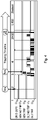
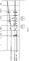
- FIG. 4 shows an example of the trip signal for the new overpressure relief flap apparatus termed "NEW TRIP" against that for an existing trip signal shown as "OLD TRIP". This shows how vibrations that affect the previous device have been mitigated in the new overpressure relief flap apparatus described here.
- the measured total tripping time of new overpressure relief flap apparatus (limiter), with respect to initiation of a short-circuit current (measured in CB compartment) is 68ms, including the opening time of the flap and a maximum opening time of the circuit breaker (60ms). The requirement is less or equal to 100ms, which has been met.
- Fig. 5 serves to explain the problems caused by vibrations in existing systems, showing debouncing of the mobile contact of a microswitch during switching. Vibrations of the mobile contact slow the coil response on a voltage step unit, and thus prolong charging time. This so-called debouncing of mobile contact previously caused several voltage interruptions as shown in Fig. 5 , where interruptions of a duration 100 ⁇ s and longer, cause current drop in the charging characteristic (see. events 1 and 2), and to an interrupted trigger signal.
- the new overpressure relief flap apparatus described here overcomes these issues.
- a tripping signal is the protection relay and electronic tripping coil inside a circuit breaker. These devices check the number of disturbances in the signal and their time duration. After exceeding a filter time, the binary state change and signal enter the logic.
- An input filter can delay tripping of circuit breaker because of disturbances in the incoming signal caused by vibrations, and therefore as the new overpressure relief flap apparatus addresses the disturbances caused on the trigger signal, such processing is improved.
Landscapes
- Physics & Mathematics (AREA)
- Fluid Mechanics (AREA)
- Engineering & Computer Science (AREA)
- Power Engineering (AREA)
- Driving Mechanisms And Operating Circuits Of Arc-Extinguishing High-Tension Switches (AREA)
- Breakers (AREA)
- Safety Valves (AREA)
Abstract
Description
- The present invention relates to an overpressure relief flap apparatus for a medium or high voltage switchgear, and to medium or high voltage switchgear having such an overpressure relief flap apparatus.
- Fortunately, flash-overs inside medium or high voltage switchgear happen rarely, but they do occur for a number of different reasons. The consequences for personnel, equipment and process may then be devastating.
- Switchgear failure through for example cable end box or busbar failure, causes a rapid expansion of air, gases and, in the case of oil filled switchgear, liquid. To mitigate this, the expanded air, gases and liquid is vented out of an overpressure relief flap within the switchgear. At the same time a switchgear circuit breaker is tripped, to make the switchgear safe.
- Currently Ith limiters (also called microswitches) are installed on the overpressure relieve flap. In case of an electrical arc or flash-over, the air pressure inside the panel rapidly increases and opens the flap as discussed above. A microswitch operates with the flap, changing the system status to OFF and at the same time providing a tripping signal for a circuit breaker. However, there are sources of vibrations during flap travel or movement, which interrupts the tripping signal.
- Thus in the current design (a microswitch / Ith limiter) is attached to flap, and vibrations are transmitted to the mobile or moveable contact of the Ith limiter microswitch during flap operation. This leads to interruption of the tripping signal. The sources of vibrations are:
- deaccelerating of the overpressure relief flap at the dead point (the mobile contact of the limiter microswitch has momentum that overcomes the force of the spring pushing the mobile contact to a solid "tripping" position, and this process leads to deceleration of the overpressure relief flap and to vibrations). This relates to protection of bus bar compartment or all compartments in case of no arc duct installation;
- impact of the Ith limiter microswitch on the side of arc duct. It relates to protection of circuit breaker and cable compartment in case of arc duct installation.
- Attempting to mitigate vibrations through tightening of the microswitch actuator can be problematic. This is because the reaction time of the Ith limiter microswitch depends on its setting. Tightening of the microswitch actuator can lead to a reduction in reaction time.
- There is a need to provide for an improved way of providing a trip signal during an electrical arc event or flash-over for a medium or high voltage switchgear.
- Therefore, it would be advantageous to have improved means for providing a trip signal during an electrical arc event or flash-over for a medium or high voltage switchgear. The object of the present invention is solved with the subject matter of the independent claims, wherein further embodiments are incorporated in the dependent claims.
- In a first aspect, there is provided an overpressure relief flap apparatus for a medium or high voltage switchgear. The apparatus comprises:
- a lever; and
- a microswitch.
- The lever is attached to an overpressure relief flap of a compartment of a switchgear. The microswitch is mounted to a frame of the compartment of the switchgear. When activated the microswitch is configured to transmit a trip signal to a circuit breaker of the switchgear. The lever is configured to activate the switch when the overpressure relief flap opens.
- In other words, a new overpressure relief flap apparatus design uses a microswitch or limiter embedded in a metal housing and a lever operating it. The Limiter (microswitch) is installed on the panel frame, whilst the lever is installed on the overpressure relieve flap. Vibrations are then not transmitted to the limiter during flap operation.
- In this way the effect of vibrations that can affect the tripping time signal are suppressed, because they are not transferred to the microswitch or limiter. In this manner, because vibrations are suppressed that would otherwise be transferred to a moveable or mobile contact of a microswitch or limiter, and uninterrupted trigger signal for a circuit breaker is provided in the situation when there is an electrical arc.
- Thus, during opening of the overpressure relief flap, for example during the first 30ms of an electrical arc, the effect of vibrations that can affect the signal transmitted by the microswitch are mitigated and the overall reaction time of the apparatus in tripping a circuit breaker is improved.
- Faster set-up and testing of the circuit breaker trip system, due to operation of an overpressure relief flap, is also provided. Additionally, the new design is significantly cheaper than previous designs.
- The trip signal as well as being used to trip the circuit breaker can be used for other purposes, such as being used to indicate that there has been an event leading to opening of the overpressure relief flap.
- In an example, an overtravel distance of the microswitch is less than 1mm.
- Thus, a contact of the microswitch moves a distance after which it activates (termed pretravel) and can then move a further distance known as the overtravel distance and this distance is kept to a minimum whilst still ensuring that switching operation takes place, thereby providing a short bouncing time and reducing the effect of vibrations.
- A microswitch having a contact with a small overtravel distance ensures that one can easily and correctly set up the limiter microswitch.
- In an example, the overtravel distance of the microswitch is approximately 0.9mm.
- In an example, the microswitch is mounted to the frame of the compartment via at least one damping component.
- In an example, the at least one damping component comprises at least one ethylene propylene diene monomer (EPDM) rubber.
- In other words, the microswitch is mounted or inserted to or into the frame of a compartment of a switchgear and is isolated from the frame/chassis by EPDM rubbers.
- In an example, the microswitch is located within a case, and the microswitch is spaced from at least one wall of the case by the at least one damping component. The case is attached to the frame of the compartment of the switchgear.
- In an example, wherein the case comprises metal.
- In an example, the lever comprises metal.
- In an example, the lever comprises one or more slotted mounted holes, oriented such that the lever can be moveably repositioned closer to or further away from the microswitch.
- In this manner. The position of the lever can be easily adjusted with respect to the microswitch, thereby making set-up easier.
- In an example, the lever is configured to enable a user to activate the microswitch with the lever when the overpressure relief flap is in a closed position.
- In an example, the lever is configured to bend to enable the user to activate the microswitch with the lever when the overpressure relief flap is in a closed position.
- In an example, a force required by the user to activate the microswitch with the lever when the overpressure relief flap is closed is less than 20N.
- In this manner, the overpressure relief flap apparatus can be efficiently tested to ensure integrity of the protection function.
- In a second aspect, there is provided a medium or high voltage switchgear comprising an overpressure relief flap apparatus according to the first aspect.
- In an example, the switchgear comprises a circuit breaker. The circuit breaker is configured to be tripped upon receipt of the trip signal transmitted from the microswitch of the overpressure relief flap apparatus.
- The above aspects and examples will become apparent from and be elucidated with reference to the embodiments described hereinafter.
- Exemplary embodiments will be described in the following with reference to the following drawings:
-
Fig. 1 shows an example of an overpressure relief flap apparatus; -
Fig. 2 shows a part of an overpressure relief flap apparatus; -
Fig. 3 shows a part of an overpressure relief flap apparatus; -
Fig. 4 shows an example of the trip signal for the overpressure relief flap apparatus of -
Figs. 1-3 in comparison to a previous system; and -
Fig. 4 shows a trip signal for a previous system. -
Figs. 1-3 show examples of an overpressure relief flap apparatus for a medium or high voltage switchgear. - These figures show an overpressure relief flap apparatus for a medium or high voltage switchgear. The apparatus comprises a
lever 4, and amicroswitch 1. The lever is shown in detail inFig. 3 and the microswitch is shown along with other components in detail inFig. 2 . The lever is attached to an overpressure relief flap of a compartment of a switchgear, as shown inFig. 1 . The overpressure relief flap is not shown in full detail inFig. 1 for reasons of clarity. The microswitch is mounted to a frame of the compartment of the switchgear, as shown inFig. 1 . The full compartment is not shown inFig. 1 again for reasons of clarity, but it is clear that these components are positioned such that when the overpressure relief flap opens, the lever contacts the microswitch to activate it. When activated the microswitch is configured to transmit a trip signal to a circuit breaker of the switchgear. The circuit breaker is not shown. The lever is configured to activate the switch when the overpressure relief flap opens. - According to an example, an overtravel distance of the microswitch is less than 1mm.
- According to an example, the overtravel distance of the microswitch is approximately 0.9mm.
- According to an example, the microswitch is mounted to the frame of the compartment via at least one damping
component 3. - According to an example, the at least one damping component comprises at least one ethylene propylene diene monomer (EPDM) rubber.
- According to an example, the microswitch is located within a
case 2. The microswitch is spaced from at least one wall of the case by the at least one damping component. The case is attached to the frame of the compartment of the switchgear. - According to an example, the case comprises metal.
- According to an example, the lever comprises metal.
- In an example, the metal is stainless steel. In an example, the metal is stainless steel 1.4310.
- According to an example, the lever comprises one or more slotted mounted holes. These are located in a base of the lever, and are oriented such that the lever can be moveably repositioned closer to or further away from the microswitch.
- According to an example, the lever is configured to enable a user to activate the microswitch with the lever when the overpressure relief flap is in a closed position.
- According to an example, the lever is configured to bend to enable the user to activate the microswitch with the lever when the overpressure relief flap is in a closed position.
- According to an example, a force required by the user to activate the microswitch with the lever when the overpressure relief flap is closed is less than 20N.
- In an example, an arm part of the lever is connected to the base part of the lever that is attached to the overpressure relief flap. The arm part extend away from the base part at an angle. In the example the angle is 65 degrees, and can be other angles. In an example, the lever is attached to the overpressure relief flap via the base part, and the arm part is angled toward the microswitch location.
- As discussed, in this way a medium or high voltage switchgear can have an overpressure relief flap apparatus as discussed above, and provides for improved way trip signal during an electrical arc event or flash-over for a medium or high voltage switchgear that can be used to trip a circuit breaker for example.
- According to an example, the switchgear comprises a circuit breaker, and wherein the circuit breaker is configured to be tripped upon receipt of the trip signal transmitted from the microswitch of the overpressure relief flap apparatus.
- Continuing with the figures,
Fig. 1 and explaining details of a specific embodiment amicroswitch 1 is used. This is a miniature Crouzet 831616 Wide contact gap microswitch that is resistant to vibrations. The microswitch is inserted in themetal case 2 and isolated byEPDM rubbers 3 from the chassis of the case. The case is itself mounted to a frame of a compartment of a medium voltage or high voltage adjacent to an overpressure relief flap, and thus the microswitch in addition to being resistant to vibrations is made more resistant to the effects of vibrations caused through mounting on the frame of the compartment and vibrationally isolating it through the use of damping EPDM rubbers. Alever 4 is used to operate the microswitch, and this is installed on the overpressure relieve flap itself. For fast setting and testing of the tripping function, the lever is made from stainless spring steel 1.4310 and can be operated by hand to activate the microswitch with a force (F < 20N).Fig. 2 shows specific details of how the microswitch is located to the case, and it is clear how the case can then be mounted to the frame of the switchgear compartment.Fig. 3 then shows specific details of the lever, again showing how it can be mounted to the overpressure relief flap and where slotted mounting slots provide adjustment means. - During an electrical arc, rapidly raised pressure (<10ms) cause the overpressure relieve flap to open upon which the lever is installed, and leading to operation of the microswitch. Electrical signal delivered to a protection circuit, trip a switchgear circuit breaker. This design suppresses vibrations transferred to the microswitch mobile or moveable contact during opening of the flap i.e. first 30ms of electrical arc and therefore speeds up reaction time.
Fig. 4 shows an example of the trip signal for the new overpressure relief flap apparatus termed "NEW TRIP" against that for an existing trip signal shown as "OLD TRIP". This shows how vibrations that affect the previous device have been mitigated in the new overpressure relief flap apparatus described here. - It is to be noted that the measured total tripping time of new overpressure relief flap apparatus (limiter), with respect to initiation of a short-circuit current (measured in CB compartment) is 68ms, including the opening time of the flap and a maximum opening time of the circuit breaker (60ms). The requirement is less or equal to 100ms, which has been met.
-
Fig. 5 serves to explain the problems caused by vibrations in existing systems, showing debouncing of the mobile contact of a microswitch during switching. Vibrations of the mobile contact slow the coil response on a voltage step unit, and thus prolong charging time. This so-called debouncing of mobile contact previously caused several voltage interruptions as shown inFig. 5 , where interruptions of a duration 100 µs and longer, cause current drop in the charging characteristic (see.events 1 and 2), and to an interrupted trigger signal. The new overpressure relief flap apparatus described here overcomes these issues. - The following examples provide further details on the overpressure relief flap apparatus:
- Example 1: An overpressure relief flap apparatus for a medium or high voltage switchgear, the apparatus comprising:
- a lever (4); and
- a microswitch (1);
- wherein, the lever is attached to an overpressure relief flap of a compartment of a switchgear;
- wherein, the microswitch is mounted to a frame of the compartment of the switchgear;
- wherein, when activated the microswitch is configured to transmit a trip signal to a circuit breaker of the switchgear; and
- wherein, the lever is configured to activate the switch when the overpressure relief flap opens.
- Example 2: The overpressure relief flap apparatus according to example 1, wherein an overtravel distance of the microswitch is less than 1mm.
- Example 3: The overpressure relief flap apparatus according to example 2, wherein the overtravel distance of the microswitch is approximately 0.9mm.
- Example 4: The overpressure relief flap apparatus according to any of examples 1-3, wherein the microswitch is mounted to the frame of the compartment via at least one damping component (3).
- Example 5: The overpressure relief flap apparatus according to example 4, wherein the at least one damping component comprises at least one ethylene propylene diene monomer (EPDM) rubber.
- Example 6: The overpressure relief flap apparatus according to any of examples 4-5, wherein the microswitch is located within a case (2), wherein the microswitch is spaced from at least one wall of the case by the at least one damping component, and wherein the case is attached to the frame of the compartment of the switchgear.
- Example 7: The overpressure relief flap apparatus according to example 6, wherein the case comprises metal.
- Example 8: The overpressure relief flap apparatus according to any of examples 1-7, wherein the lever comprises metal.
- Example 9: The overpressure relief flap apparatus according to any of examples 1-8, wherein the lever comprises one or more slotted mounted holes, oriented such that the lever can be moveably repositioned closer to or further away from the microswitch.
- Example 10: The overpressure relief flap apparatus according to any of examples 1-8, wherein the lever is configured to enable a user to activate the microswitch with the lever when the overpressure relief flap is in a closed position.
- Example 11: The overpressure relief flap apparatus according to example 10, wherein the lever is configured to bend to enable the user to activate the microswitch with the lever when the overpressure relief flap is in a closed position.
- Example 12: the overpressure relief flap apparatus according to any of examples 10-11, wherein a force required by the user to activate the microswitch with the lever when the overpressure relief flap is closed is less than 20N.
- Example 13: A medium or high voltage switchgear comprising an overpressure relief flap apparatus according to any of examples 1-12.
- Example 14: The medium or high voltage switchgear according to example 13, wherein the switchgear comprises a circuit breaker, and wherein the circuit breaker is configured to be tripped upon receipt of the trip signal transmitted from the microswitch of the overpressure relief flap apparatus.
- It is to be noted that another method of processing a tripping signal is the protection relay and electronic tripping coil inside a circuit breaker. These devices check the number of disturbances in the signal and their time duration. After exceeding a filter time, the binary state change and signal enter the logic. An input filter can delay tripping of circuit breaker because of disturbances in the incoming signal caused by vibrations, and therefore as the new overpressure relief flap apparatus addresses the disturbances caused on the trigger signal, such processing is improved.
-
- 1 Microswitch
- 2 Metal case
- 3 Damping component - e.g. EPDM rubber
- 4 Lever
Claims (15)
- An overpressure relief flap apparatus for a medium or high voltage switchgear, the apparatus comprising:- a lever (4); and- a microswitch (1);wherein, the lever is attached to an overpressure relief flap of a compartment of a switchgear;wherein, the microswitch is mounted to a frame of the compartment of the switchgear;wherein, when activated the microswitch is configured to transmit a trip signal to a circuit breaker of the switchgear;wherein, the lever is configured to activate the switch when the overpressure relief flap opens; andwherein the lever is configured to enable a user to activate the microswitch with the lever when the overpressure relief flap is in a closed position.
- Overpressure relief flap apparatus according to claim 1, wherein an overtravel distance of the microswitch is less than 1mm.
- Overpressure relief flap apparatus according to claim 2, wherein the overtravel distance of the microswitch is approximately 0.9mm.
- Overpressure relief flap apparatus according to any of claims 1-3, wherein the lever comprises metal.
- Overpressure relief flap apparatus according to any of claims 1-4, wherein the lever comprises one or more slotted mounted holes, oriented such that the lever can be moveably repositioned closer to or further away from the microswitch.
- Overpressure relief flap apparatus according to any of claims 1-5, wherein the lever is configured to bend to enable the user to activate the microswitch with the lever when the overpressure relief flap is in a closed position.
- Overpressure relief flap apparatus according to any of claims 1-6, wherein a force required by the user to activate the microswitch with the lever when the overpressure relief flap is closed is less than 20N.
- An overpressure relief flap apparatus for a medium or high voltage switchgear, the apparatus comprising:- a lever (4); and- a microswitch (1);wherein, the lever is attached to an overpressure relief flap of a compartment of a switchgear;wherein, the microswitch is mounted to a frame of the compartment of the switchgear;wherein, when activated the microswitch is configured to transmit a trip signal to a circuit breaker of the switchgear;wherein, the lever is configured to activate the switch when the overpressure relief flap opens;wherein an overtravel distance of the microswitch is less than 1mm; andwherein the overtravel distance of the microswitch is approximately 0.9mm.
- Overpressure relief flap apparatus according to claim 8, wherein the lever comprises metal.
- Overpressure relief flap apparatus according to any of claims 8-9, wherein the lever comprises one or more slotted mounted holes, oriented such that the lever can be moveably repositioned closer to or further away from the microswitch.
- Overpressure relief flap apparatus according to any of claims 8-10, wherein the lever is configured to enable a user to activate the microswitch with the lever when the overpressure relief flap is in a closed position.
- Overpressure relief flap apparatus according to claim 11, wherein the lever is configured to bend to enable the user to activate the microswitch with the lever when the overpressure relief flap is in a closed position.
- Overpressure relief flap apparatus according to any of claims 11-12, wherein a force required by the user to activate the microswitch with the lever when the overpressure relief flap is closed is less than 20N.
- A medium or high voltage switchgear comprising an overpressure relief flap apparatus according to any of claims 1-7 or an overpressure relief flap apparatus according to any of claims 8-13.
- Medium or high voltage switchgear according to claim 14, wherein the switchgear comprises a circuit breaker, and wherein the circuit breaker is configured to be tripped upon receipt of the trip signal transmitted from the microswitch of the overpressure relief flap apparatus.
Priority Applications (2)
| Application Number | Priority Date | Filing Date | Title |
|---|---|---|---|
| ES22181261T ES3032954T3 (en) | 2018-12-17 | 2018-12-17 | Overpressure relief flap apparatus for a medium or high voltage switchgear |
| EP22181261.3A EP4109481B1 (en) | 2018-12-17 | 2018-12-17 | Overpressure relief flap apparatus for a medium or high voltage switchgear |
Applications Claiming Priority (2)
| Application Number | Priority Date | Filing Date | Title |
|---|---|---|---|
| EP22181261.3A EP4109481B1 (en) | 2018-12-17 | 2018-12-17 | Overpressure relief flap apparatus for a medium or high voltage switchgear |
| EP18213060.9A EP3671788B1 (en) | 2018-12-17 | 2018-12-17 | Overpressure relief flap apparatus for a medium or high voltage switchgear |
Related Parent Applications (2)
| Application Number | Title | Priority Date | Filing Date |
|---|---|---|---|
| EP18213060.9A Division EP3671788B1 (en) | 2018-12-17 | 2018-12-17 | Overpressure relief flap apparatus for a medium or high voltage switchgear |
| EP18213060.9A Division-Into EP3671788B1 (en) | 2018-12-17 | 2018-12-17 | Overpressure relief flap apparatus for a medium or high voltage switchgear |
Publications (2)
| Publication Number | Publication Date |
|---|---|
| EP4109481A1 true EP4109481A1 (en) | 2022-12-28 |
| EP4109481B1 EP4109481B1 (en) | 2025-03-26 |
Family
ID=64744440
Family Applications (2)
| Application Number | Title | Priority Date | Filing Date |
|---|---|---|---|
| EP22181261.3A Active EP4109481B1 (en) | 2018-12-17 | 2018-12-17 | Overpressure relief flap apparatus for a medium or high voltage switchgear |
| EP18213060.9A Active EP3671788B1 (en) | 2018-12-17 | 2018-12-17 | Overpressure relief flap apparatus for a medium or high voltage switchgear |
Family Applications After (1)
| Application Number | Title | Priority Date | Filing Date |
|---|---|---|---|
| EP18213060.9A Active EP3671788B1 (en) | 2018-12-17 | 2018-12-17 | Overpressure relief flap apparatus for a medium or high voltage switchgear |
Country Status (3)
| Country | Link |
|---|---|
| EP (2) | EP4109481B1 (en) |
| CN (1) | CN111326367B (en) |
| ES (1) | ES3032954T3 (en) |
Families Citing this family (1)
| Publication number | Priority date | Publication date | Assignee | Title |
|---|---|---|---|---|
| EP3952043A1 (en) | 2020-08-04 | 2022-02-09 | ABB Schweiz AG | Arc apparatus for an air insulated switchgear |
Citations (3)
| Publication number | Priority date | Publication date | Assignee | Title |
|---|---|---|---|---|
| US2773146A (en) * | 1954-11-23 | 1956-12-04 | Westinghouse Electric Corp | Pressure switch |
| WO2001016984A1 (en) * | 1999-08-30 | 2001-03-08 | Eaton Corporation | Circuit breaker with two piece bell accessory lever with overtravel |
| DE102009010229A1 (en) * | 2009-02-24 | 2010-08-26 | Siemens Aktiengesellschaft | Tripping device for electrical switching arrangement, has switch, which is operated by pressure, where electrical signal of converter is provided with operating element |
Family Cites Families (2)
| Publication number | Priority date | Publication date | Assignee | Title |
|---|---|---|---|---|
| CN100568435C (en) * | 2006-12-19 | 2009-12-09 | 詹奇峰 | Automatic pneumatic switch for air compressor |
| EP2169795A1 (en) * | 2008-09-26 | 2010-03-31 | Eaton Electric B.V. | Switching installation with arc protection and arc protection method |
-
2018
- 2018-12-17 EP EP22181261.3A patent/EP4109481B1/en active Active
- 2018-12-17 EP EP18213060.9A patent/EP3671788B1/en active Active
- 2018-12-17 ES ES22181261T patent/ES3032954T3/en active Active
-
2019
- 2019-12-16 CN CN201911294334.3A patent/CN111326367B/en active Active
Patent Citations (3)
| Publication number | Priority date | Publication date | Assignee | Title |
|---|---|---|---|---|
| US2773146A (en) * | 1954-11-23 | 1956-12-04 | Westinghouse Electric Corp | Pressure switch |
| WO2001016984A1 (en) * | 1999-08-30 | 2001-03-08 | Eaton Corporation | Circuit breaker with two piece bell accessory lever with overtravel |
| DE102009010229A1 (en) * | 2009-02-24 | 2010-08-26 | Siemens Aktiengesellschaft | Tripping device for electrical switching arrangement, has switch, which is operated by pressure, where electrical signal of converter is provided with operating element |
Also Published As
| Publication number | Publication date |
|---|---|
| EP4109481B1 (en) | 2025-03-26 |
| CN111326367A (en) | 2020-06-23 |
| ES3032954T3 (en) | 2025-07-29 |
| EP3671788B1 (en) | 2022-08-31 |
| CN111326367B (en) | 2023-01-03 |
| EP3671788A1 (en) | 2020-06-24 |
Similar Documents
| Publication | Publication Date | Title |
|---|---|---|
| US8492672B2 (en) | Insulated arc flash arrester | |
| US6141192A (en) | Arcing fault protection system for a switchgear enclosure | |
| US8138862B2 (en) | Double break installation switchgear | |
| JP3589061B2 (en) | Vacuum switchgear and method for opening and closing vacuum switchgear | |
| US7986061B2 (en) | Electrical switching device | |
| EP3956916B1 (en) | Guiding pull ring | |
| EP4109481B1 (en) | Overpressure relief flap apparatus for a medium or high voltage switchgear | |
| EP3987558B1 (en) | Switch-disconnector with current detection | |
| EP3104385B1 (en) | Retaining assembly for a circuit breaker contact system | |
| KR102095408B1 (en) | Arc Eliminator | |
| US20090008229A1 (en) | Contact system for a short-circuiting device in a medium-voltage or high-voltage switchboard plant | |
| US10665410B2 (en) | Circuit breaker including active arc control features | |
| US20200112159A1 (en) | Arc flash detection apparatus and electrical system including the same | |
| EP3690907A1 (en) | Narrow profile circuit breaker with arc interruption | |
| EP4235989A1 (en) | Gas-insulated switchgear | |
| EP3073507B1 (en) | Apparatus for auxiliary contact of circuit breaker | |
| US9576753B2 (en) | Moveable contact arm releases latch plate engagement in a circuit breaker | |
| US9947486B2 (en) | Switch unit, in particular a circuit breaker | |
| US9595404B2 (en) | Electrical switching apparatus including an adjustable damper assembly | |
| KR20160097036A (en) | Gas insulation switch | |
| KR20230099135A (en) | High Speed Earthing Switch of Gas Insulated Switchgear and Gas Insulated Switchgear having the same | |
| KR100576307B1 (en) | High pressure equipment opening and closing rebound prevention device | |
| Gentsch et al. | New Ultra Fast Earthing Switch (UFES) device based on the vacuum switching principle | |
| US9741512B2 (en) | Switchgear system, and electrical switching apparatus assembly and maintaining method therefor | |
| KR20160001271U (en) | Gas insulated switchgear |
Legal Events
| Date | Code | Title | Description |
|---|---|---|---|
| PUAI | Public reference made under article 153(3) epc to a published international application that has entered the european phase |
Free format text: ORIGINAL CODE: 0009012 |
|
| STAA | Information on the status of an ep patent application or granted ep patent |
Free format text: STATUS: THE APPLICATION HAS BEEN PUBLISHED |
|
| AC | Divisional application: reference to earlier application |
Ref document number: 3671788 Country of ref document: EP Kind code of ref document: P |
|
| AK | Designated contracting states |
Kind code of ref document: A1 Designated state(s): AL AT BE BG CH CY CZ DE DK EE ES FI FR GB GR HR HU IE IS IT LI LT LU LV MC MK MT NL NO PL PT RO RS SE SI SK SM TR |
|
| STAA | Information on the status of an ep patent application or granted ep patent |
Free format text: STATUS: REQUEST FOR EXAMINATION WAS MADE |
|
| 17P | Request for examination filed |
Effective date: 20230322 |
|
| RBV | Designated contracting states (corrected) |
Designated state(s): AL AT BE BG CH CY CZ DE DK EE ES FI FR GB GR HR HU IE IS IT LI LT LU LV MC MK MT NL NO PL PT RO RS SE SI SK SM TR |
|
| GRAP | Despatch of communication of intention to grant a patent |
Free format text: ORIGINAL CODE: EPIDOSNIGR1 |
|
| STAA | Information on the status of an ep patent application or granted ep patent |
Free format text: STATUS: GRANT OF PATENT IS INTENDED |
|
| INTG | Intention to grant announced |
Effective date: 20241021 |
|
| GRAS | Grant fee paid |
Free format text: ORIGINAL CODE: EPIDOSNIGR3 |
|
| GRAA | (expected) grant |
Free format text: ORIGINAL CODE: 0009210 |
|
| STAA | Information on the status of an ep patent application or granted ep patent |
Free format text: STATUS: THE PATENT HAS BEEN GRANTED |
|
| AC | Divisional application: reference to earlier application |
Ref document number: 3671788 Country of ref document: EP Kind code of ref document: P |
|
| AK | Designated contracting states |
Kind code of ref document: B1 Designated state(s): AL AT BE BG CH CY CZ DE DK EE ES FI FR GB GR HR HU IE IS IT LI LT LU LV MC MK MT NL NO PL PT RO RS SE SI SK SM TR |
|
| REG | Reference to a national code |
Ref country code: GB Ref legal event code: FG4D |
|
| REG | Reference to a national code |
Ref country code: CH Ref legal event code: EP |
|
| REG | Reference to a national code |
Ref country code: DE Ref legal event code: R096 Ref document number: 602018080628 Country of ref document: DE |
|
| REG | Reference to a national code |
Ref country code: IE Ref legal event code: FG4D |
|
| PG25 | Lapsed in a contracting state [announced via postgrant information from national office to epo] |
Ref country code: RS Free format text: LAPSE BECAUSE OF FAILURE TO SUBMIT A TRANSLATION OF THE DESCRIPTION OR TO PAY THE FEE WITHIN THE PRESCRIBED TIME-LIMIT Effective date: 20250626 |
|
| PG25 | Lapsed in a contracting state [announced via postgrant information from national office to epo] |
Ref country code: FI Free format text: LAPSE BECAUSE OF FAILURE TO SUBMIT A TRANSLATION OF THE DESCRIPTION OR TO PAY THE FEE WITHIN THE PRESCRIBED TIME-LIMIT Effective date: 20250326 |
|
| REG | Reference to a national code |
Ref country code: LT Ref legal event code: MG9D |
|
| PG25 | Lapsed in a contracting state [announced via postgrant information from national office to epo] |
Ref country code: NO Free format text: LAPSE BECAUSE OF FAILURE TO SUBMIT A TRANSLATION OF THE DESCRIPTION OR TO PAY THE FEE WITHIN THE PRESCRIBED TIME-LIMIT Effective date: 20250626 |
|
| PG25 | Lapsed in a contracting state [announced via postgrant information from national office to epo] |
Ref country code: HR Free format text: LAPSE BECAUSE OF FAILURE TO SUBMIT A TRANSLATION OF THE DESCRIPTION OR TO PAY THE FEE WITHIN THE PRESCRIBED TIME-LIMIT Effective date: 20250326 |
|
| PG25 | Lapsed in a contracting state [announced via postgrant information from national office to epo] |
Ref country code: LV Free format text: LAPSE BECAUSE OF FAILURE TO SUBMIT A TRANSLATION OF THE DESCRIPTION OR TO PAY THE FEE WITHIN THE PRESCRIBED TIME-LIMIT Effective date: 20250326 |
|
| PG25 | Lapsed in a contracting state [announced via postgrant information from national office to epo] |
Ref country code: BG Free format text: LAPSE BECAUSE OF FAILURE TO SUBMIT A TRANSLATION OF THE DESCRIPTION OR TO PAY THE FEE WITHIN THE PRESCRIBED TIME-LIMIT Effective date: 20250326 Ref country code: GR Free format text: LAPSE BECAUSE OF FAILURE TO SUBMIT A TRANSLATION OF THE DESCRIPTION OR TO PAY THE FEE WITHIN THE PRESCRIBED TIME-LIMIT Effective date: 20250627 |
|
| REG | Reference to a national code |
Ref country code: ES Ref legal event code: FG2A Ref document number: 3032954 Country of ref document: ES Kind code of ref document: T3 Effective date: 20250729 |
|
| REG | Reference to a national code |
Ref country code: NL Ref legal event code: MP Effective date: 20250326 |
|
| PG25 | Lapsed in a contracting state [announced via postgrant information from national office to epo] |
Ref country code: NL Free format text: LAPSE BECAUSE OF FAILURE TO SUBMIT A TRANSLATION OF THE DESCRIPTION OR TO PAY THE FEE WITHIN THE PRESCRIBED TIME-LIMIT Effective date: 20250326 |
|
| PG25 | Lapsed in a contracting state [announced via postgrant information from national office to epo] |
Ref country code: SE Free format text: LAPSE BECAUSE OF FAILURE TO SUBMIT A TRANSLATION OF THE DESCRIPTION OR TO PAY THE FEE WITHIN THE PRESCRIBED TIME-LIMIT Effective date: 20250326 |
|
| REG | Reference to a national code |
Ref country code: AT Ref legal event code: MK05 Ref document number: 1779823 Country of ref document: AT Kind code of ref document: T Effective date: 20250326 |
|
| PG25 | Lapsed in a contracting state [announced via postgrant information from national office to epo] |
Ref country code: SM Free format text: LAPSE BECAUSE OF FAILURE TO SUBMIT A TRANSLATION OF THE DESCRIPTION OR TO PAY THE FEE WITHIN THE PRESCRIBED TIME-LIMIT Effective date: 20250326 |
|
| PG25 | Lapsed in a contracting state [announced via postgrant information from national office to epo] |
Ref country code: PT Free format text: LAPSE BECAUSE OF FAILURE TO SUBMIT A TRANSLATION OF THE DESCRIPTION OR TO PAY THE FEE WITHIN THE PRESCRIBED TIME-LIMIT Effective date: 20250728 |
|
| PG25 | Lapsed in a contracting state [announced via postgrant information from national office to epo] |
Ref country code: PL Free format text: LAPSE BECAUSE OF FAILURE TO SUBMIT A TRANSLATION OF THE DESCRIPTION OR TO PAY THE FEE WITHIN THE PRESCRIBED TIME-LIMIT Effective date: 20250326 |
|
| PG25 | Lapsed in a contracting state [announced via postgrant information from national office to epo] |
Ref country code: AT Free format text: LAPSE BECAUSE OF FAILURE TO SUBMIT A TRANSLATION OF THE DESCRIPTION OR TO PAY THE FEE WITHIN THE PRESCRIBED TIME-LIMIT Effective date: 20250326 |
|
| PG25 | Lapsed in a contracting state [announced via postgrant information from national office to epo] |
Ref country code: EE Free format text: LAPSE BECAUSE OF FAILURE TO SUBMIT A TRANSLATION OF THE DESCRIPTION OR TO PAY THE FEE WITHIN THE PRESCRIBED TIME-LIMIT Effective date: 20250326 |
|
| PG25 | Lapsed in a contracting state [announced via postgrant information from national office to epo] |
Ref country code: RO Free format text: LAPSE BECAUSE OF FAILURE TO SUBMIT A TRANSLATION OF THE DESCRIPTION OR TO PAY THE FEE WITHIN THE PRESCRIBED TIME-LIMIT Effective date: 20250326 |
|
| PG25 | Lapsed in a contracting state [announced via postgrant information from national office to epo] |
Ref country code: SK Free format text: LAPSE BECAUSE OF FAILURE TO SUBMIT A TRANSLATION OF THE DESCRIPTION OR TO PAY THE FEE WITHIN THE PRESCRIBED TIME-LIMIT Effective date: 20250326 |
|
| PG25 | Lapsed in a contracting state [announced via postgrant information from national office to epo] |
Ref country code: IS Free format text: LAPSE BECAUSE OF FAILURE TO SUBMIT A TRANSLATION OF THE DESCRIPTION OR TO PAY THE FEE WITHIN THE PRESCRIBED TIME-LIMIT Effective date: 20250726 |
|
| REG | Reference to a national code |
Ref country code: DE Ref legal event code: R097 Ref document number: 602018080628 Country of ref document: DE |
|
| PGFP | Annual fee paid to national office [announced via postgrant information from national office to epo] |
Ref country code: DE Payment date: 20251211 Year of fee payment: 8 |
|
| PG25 | Lapsed in a contracting state [announced via postgrant information from national office to epo] |
Ref country code: DK Free format text: LAPSE BECAUSE OF FAILURE TO SUBMIT A TRANSLATION OF THE DESCRIPTION OR TO PAY THE FEE WITHIN THE PRESCRIBED TIME-LIMIT Effective date: 20250326 |
|
| PGFP | Annual fee paid to national office [announced via postgrant information from national office to epo] |
Ref country code: IT Payment date: 20251223 Year of fee payment: 8 |
|
| PGFP | Annual fee paid to national office [announced via postgrant information from national office to epo] |
Ref country code: FR Payment date: 20251229 Year of fee payment: 8 |
|
| PG25 | Lapsed in a contracting state [announced via postgrant information from national office to epo] |
Ref country code: CZ Free format text: LAPSE BECAUSE OF FAILURE TO SUBMIT A TRANSLATION OF THE DESCRIPTION OR TO PAY THE FEE WITHIN THE PRESCRIBED TIME-LIMIT Effective date: 20250326 |
|
| PLBE | No opposition filed within time limit |
Free format text: ORIGINAL CODE: 0009261 |
|
| STAA | Information on the status of an ep patent application or granted ep patent |
Free format text: STATUS: NO OPPOSITION FILED WITHIN TIME LIMIT |
|
| REG | Reference to a national code |
Ref country code: CH Ref legal event code: L10 Free format text: ST27 STATUS EVENT CODE: U-0-0-L10-L00 (AS PROVIDED BY THE NATIONAL OFFICE) Effective date: 20260211 |
|
| 26N | No opposition filed |
Effective date: 20260105 |
|
| PGFP | Annual fee paid to national office [announced via postgrant information from national office to epo] |
Ref country code: ES Payment date: 20260130 Year of fee payment: 8 |