EP4109427A1 - Paper sheet handling device - Google Patents
Paper sheet handling device Download PDFInfo
- Publication number
- EP4109427A1 EP4109427A1 EP20920209.2A EP20920209A EP4109427A1 EP 4109427 A1 EP4109427 A1 EP 4109427A1 EP 20920209 A EP20920209 A EP 20920209A EP 4109427 A1 EP4109427 A1 EP 4109427A1
- Authority
- EP
- European Patent Office
- Prior art keywords
- section
- banknote
- conveyance
- taking
- paper sheet
- Prior art date
- Legal status (The legal status is an assumption and is not a legal conclusion. Google has not performed a legal analysis and makes no representation as to the accuracy of the status listed.)
- Granted
Links
Images






Classifications
-
- G—PHYSICS
- G07—CHECKING-DEVICES
- G07D—HANDLING OF COINS OR VALUABLE PAPERS, e.g. TESTING, SORTING BY DENOMINATIONS, COUNTING, DISPENSING, CHANGING OR DEPOSITING
- G07D11/00—Devices accepting coins; Devices accepting, dispensing, sorting or counting valuable papers
- G07D11/10—Mechanical details
- G07D11/14—Inlet or outlet ports
-
- G—PHYSICS
- G07—CHECKING-DEVICES
- G07D—HANDLING OF COINS OR VALUABLE PAPERS, e.g. TESTING, SORTING BY DENOMINATIONS, COUNTING, DISPENSING, CHANGING OR DEPOSITING
- G07D11/00—Devices accepting coins; Devices accepting, dispensing, sorting or counting valuable papers
- G07D11/40—Device architecture, e.g. modular construction
-
- B—PERFORMING OPERATIONS; TRANSPORTING
- B65—CONVEYING; PACKING; STORING; HANDLING THIN OR FILAMENTARY MATERIAL
- B65H—HANDLING THIN OR FILAMENTARY MATERIAL, e.g. SHEETS, WEBS, CABLES
- B65H2301/00—Handling processes for sheets or webs
- B65H2301/40—Type of handling process
- B65H2301/43—Gathering; Associating; Assembling
- B65H2301/431—Features with regard to the collection, nature, sequence and/or the making thereof
- B65H2301/4314—Making packets of bundles of banknotes or the like in correct sequence
-
- G—PHYSICS
- G07—CHECKING-DEVICES
- G07D—HANDLING OF COINS OR VALUABLE PAPERS, e.g. TESTING, SORTING BY DENOMINATIONS, COUNTING, DISPENSING, CHANGING OR DEPOSITING
- G07D11/00—Devices accepting coins; Devices accepting, dispensing, sorting or counting valuable papers
- G07D11/10—Mechanical details
- G07D11/12—Containers for valuable papers
- G07D11/13—Containers for valuable papers with internal means for handling valuable papers
-
- G—PHYSICS
- G07—CHECKING-DEVICES
- G07D—HANDLING OF COINS OR VALUABLE PAPERS, e.g. TESTING, SORTING BY DENOMINATIONS, COUNTING, DISPENSING, CHANGING OR DEPOSITING
- G07D2211/00—Paper-money handling devices
Definitions
- the present invention relates to a paper sheet handling apparatus.
- a paper sheet insertion/withdrawal apparatus which includes: a first moving member between a pair of moving members which sandwich paper sheets inserted by a customer, the first moving member sandwiching the paper sheets from a side close to a feeding unit and moving the paper sheets from a position where the paper sheets are inserted into the feeding unit; rollers of the feeding unit, which protrude from a gap on the first moving member to a storage space of the paper sheets and convey the paper sheets; and a shield member driven by a motor to close the gap when the first moving member is located at the position where the paper sheets are inserted and to retreat when the first moving member moves to the feeding unit (for example, refer to Patent Literature 1).
- Patent Literature 1 JP 2015-156130 A
- a banknote insertion/withdrawal unit is disposed in order to insert a banknote to be deposited and in order to take out a banknote to be withdrawn.
- a banknote insertion/withdrawal unit including: a stage and a roof which are arranged to face each other with an insertion space interposed therebetween, the insertion space having paper sheets inserted from an insertion port; and a conveyance section that conveys the paper sheets inserted into this insertion space in a state of protruding from an opening portion of the stage toward the insertion space.
- the opening portion When the opening portion is provided in the stage as described above, a foreign object enters an inside of the apparatus from the insertion space through the opening portion of the stage. Accordingly, if the opening portion of the stage is closed by arranging the above-mentioned shield member and motor in order to prevent the entry of the foreign object from the insertion space, then the motor is required, and in addition, a power transmission mechanism that transmits power from the motor to the shield member is required. Therefore, a structure of the banknote insertion/withdrawal unit will be complicated.
- a paper sheet handling apparatus includes: a first facing section and a second facing section which are arranged so as to face each other with an insertion space interposed therebetween, the insertion space having a paper sheet inserted from an insertion port; and a conveyance section that, in a state of protruding from a first opening portion of the first facing section toward the insertion space, conveys the paper sheet inserted into the insertion space, wherein the first facing section includes a first shutter that openably closes the first opening portion, the first facing section is disposed so as to be movable, in a facing direction where the first facing section and the second facing section face each other, to an insertion position at a time when the paper sheet is inserted and a conveyance position at a time when the paper sheet is conveyed by the conveyance section, and the first facing section and the conveyance section include first shutter opening/closing units which open the first opening portion by meshing with each other to open the first shutter when the first facing section moves from the insertion position to the conveyance position.
- the entry of the foreign object from the insertion space into which the paper sheets are inserted from the insertion port can be prevented.
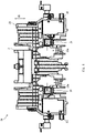
- Fig. 1 is a left side view illustrating an internal configuration of the automatic transaction apparatus 100.
- up/down, front/rear and left/right directions illustrated in Fig. 1 and Figs. 2A to 4B which will be mentioned later are merely examples in a case where a customer side of the automatic transaction apparatus 100 is in the front direction; however, for example, the up/down direction is a vertical direction, and the front/rear direction and the left/right direction are horizontal directions.
- the automatic transaction apparatus 100 illustrated in Fig. 1 is, for example, an ATM, a bill recycle unit (BRU), a cash dispenser (CD), a teller cash recycler (TCR), or the like, and includes a main body unit 110, an intermediate conveyance section 120, and a storage unit 130.
- the main body unit 110 and the storage unit 130 are arranged in different spaces with a partition (not shown) interposed therebetween, and the intermediate conveyance section 120 conveys a banknote B (see Fig. 2A ) so as to penetrate the above-described partition.
- the banknote B is an example of paper sheets.
- the main body unit 110 includes a banknote insertion/withdrawal unit 1, conveyance sections 111 and 113, an identification unit 112, a temporarily holding unit 114, and a reject unit 115.
- the banknote insertion/withdrawal unit 1 includes a stage 10, a roof 20, a pusher 30, a taking-in conveyance section 40, a discharge conveyance section 50, a front panel 60, a shutter 70, a first contact section 80 (see Fig. 3A ), and a banknote receiving section 90 (see Fig. 9 ). Note that only the banknote insertion/withdrawal unit 1 may be regarded as an example of the paper sheet handling apparatus.
- the stage 10, the roof 20, the pusher 30, the taking-in conveyance section 40, the first contact section 80, and the banknote receiving section 90 will be described later with reference to Figs. 3A to 3C , Figs. 4A and 4B , and Figs. 5 to 9 .
- the taking-in conveyance section 40 conveys the banknote B, which is inserted between the stage 10 and the pusher 30, thereby taking the banknote B into the automatic transaction apparatus 100.
- the discharge conveyance section 50 discharges the banknote B to between the roof 20 and the pusher 30.
- the front panel 60 On an upper front surface of the automatic transaction apparatus 100, the front panel 60 is disposed to be inclined with respect to the vertical direction and the horizontal direction so as to be located rearward as going upward.
- the front panel 60 is provided with an insertion/taking-out port 61.
- the shutter 70 openably closes the insertion/taking-out port 61. Note that, in Fig. 1 , the shutter 70 in an opened state is illustrated by a solid line, and the shutter 70 in a closed state is illustrated by a dotted line.
- the conveyance section 111 conveys the banknote B from the banknote insertion/withdrawal unit 1 to the identification unit 112, and conveys the banknote B between the identification unit 112 and the intermediate conveyance section 120.
- the identification unit 112 determines authenticity, dirt, corner bent and the like of the banknote B.
- the conveyance section 113 conveys the banknote B between the identification unit 112 and the temporarily holding unit 114, and conveys the banknote B from the identification unit 112 to the banknote insertion/withdrawal unit 1.
- the temporarily holding unit 114 temporarily stores the banknote B that is inserted into the banknote insertion/withdrawal unit 1 and determined to be normal in the identification unit 112.
- the reject unit 115 stores a banknote B, which is not to be returned, among such banknotes B determined to be abnormal in the identification unit 112.
- the intermediate conveyance section 120 conveys the banknote B between the main body unit 110 and the storage unit 130.
- the storage unit 130 is disposed below the main body unit 110, and includes a plurality of banknote storage cassettes 131, 132, 133, 134, and 135, and a storage conveyance section 136.
- the plurality of banknote storage cassettes 131 to 135 store, for example, such banknotes B of which money types are different from one another.
- the banknote storage cassettes 131 to 135 are capable of discharging the banknotes B stored therein. Therefore, the banknotes B stored in the banknote storage cassettes 131 to 135 are used for withdrawal.
- the storage conveyance section 136 conveys the banknotes B between the intermediate conveyance section 120 and the respective banknote storage cassettes 131 to 135.
- Figs. 2A to 2C are explanatory views for explaining conveyance routes R1 to R4 of the automatic transaction apparatus 100 for the banknotes B.
- banknotes B inserted into the banknote insertion/withdrawal unit 1 are conveyed to the identification unit 112 by the taking-in conveyance section 40 and the conveyance section 111. Moreover, such banknotes B determined to be normal in the identification unit 112 are conveyed to the temporarily holding unit 114 by the conveyance section 113.
- banknotes B (counterfeit banknotes and the like) determined to be abnormal in the identification unit 112 are returned to the banknote insertion/withdrawal unit 1 by the conveyance section 113 and the discharge conveyance section 50.
- banknotes B temporarily stored in the temporarily holding unit 114 are conveyed to the respective banknote storage cassettes 131 to 135 by the conveyance section 113, the identification unit 112, the conveyance section 111, the intermediate conveyance section 120, and the storage conveyance section 136.
- the banknotes B stored in the respective banknote storage cassettes 131 to 135 are discharged, at the time of withdrawal, to the banknote insertion/withdrawal unit 1 by the storage conveyance section 136, the intermediate conveyance section 120, the conveyance section 111, the identification unit 112, the conveyance section 113, and the discharge conveyance section 50.
- Figs. 3A to 3C are explanatory views for explaining the banknote inserting operation of the banknote insertion/withdrawal unit 1.
- Figs. 4A and 4B are explanatory views for explaining the remaining banknote taking-in operation of the banknote insertion/withdrawal unit 1.
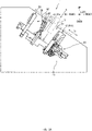
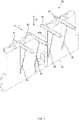
- Fig. 5 is a view of the stage 10 when viewed from a direction V in Fig. 3B .
- Fig. 6 is a view of the stage 10 when viewed from a direction VI in Fig. 3C .
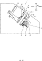
- Fig. 7 is a view of the pusher 30 when viewed from a direction VII in Fig. 4A .
- Fig. 8 is a view of the pusher 30 when viewed from a direction VIII in Fig. 4B .
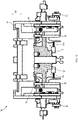
- Fig. 9 is a perspective view illustrating the banknote receiving section 90.
- the stage 10 and the roof 20 are arranged so as to face each other with an insertion space S1 interposed therebetween.
- the banknote B is inserted from the insertion/taking-out port 61 of the front panel 60, which is shown by a chain double-dashed line in each of Figs. 3A to 4B .
- a facing direction D1 where the stage 10 and the roof 20 face each other is perpendicular to the insertion/taking-out direction D2, and is inclined in the vertical direction and the horizontal direction so as to be located upward as going rearward.
- the stage 10 includes a stage main body 11, two first shutters 12 (hatched portions), two gears 13, two gears 14, and two racks 15. Note that the stage 10 is an example of a first facing section.
- the stage 10 is disposed so as to be movable to an insertion position P11 (see Figs. 3A and 3B ) at the time when the banknote B is inserted and a conveyance position P12 (see Fig. 3C ) at the time when the banknote B is conveyed by pick rollers 41 in the facing direction D1 where the stage 10 and the roof 20 face each other.
- the stage main body 11 is provided with two first opening portions 11a penetrated by the pick rollers 41 of the taking-in conveyance section 40 to be described later.
- the two first shutters 12 openably close the first opening portions 11a.
- the two gears 13 are provided on left and right end portions on a lower end of the stage 10 (the stage main body 11). At the time when the stage 10 moves from the insertion position P11 illustrated in Figs. 3A and 3B to the conveyance position P12 illustrated in Fig. 3C , the two gears 13 rotate by meshing with two racks 42 of the taking-in conveyance section 40 to be described later.
- the two gears 14 rotate following the rotation of the two gears 13.
- the two racks 15 move up and down following the rotation of the two gears 14.
- the two racks 15 are provided integrally with the first shutters 12, or are fixed to the first shutters 12.
- the two gears 13 rotate by meshing with the two racks 42 of the taking-in conveyance section 40, whereby the two gears 14 rotate, the two racks 15 ascend, and the two first shutters 12 ascend.
- the two first shutters 12 open so as to open the two first opening portions 11a.
- the two gears 13 reversely rotate by meshing with the two racks 42 of the taking-in conveyance section 40, whereby the two gears 14 reversely rotate, the two racks 15 descend, and the two first shutters 12 descend.
- the two first shutters 12 close the two first opening portions 11a.
- the two gears 13, the two gears 14 and the two racks 15 in the stage 10 are an example of a first shutter opening/closing unit provided in the stage 10.
- the two racks 42 of the taking-in conveyance section 40 are an example of a first shutter opening/closing unit provided int he taking-in conveyance section 40.
- an opening/closing direction of the two first shutters 12 is not limited to the up/down direction, and may be the left/right direction. Further, the two first shutters 12 may move not upward but downward when opening. As described above, the opening/closing direction of the first shutters 12 is arbitrary. Moreover, though two pieces of the first opening portions 11a are provided according to the number of pick rollers 41, the number may be one, or may be three or more. Further, when the first shutter 12 that is single closes a plurality of the first opening portions 11a, the number of first shutters 12 may be smaller than the number of first opening portions 11a.
- the roof 20 is movable in the facing direction D1. Note that the roof 20 is an example of a second facing section.
- the pusher 30 includes a movable member 31, a rotating shaft 32, a pusher main body 33, two second shutters 34 (hatched portions), two rollers 35, two gears 36, and two racks 37.
- the pusher 30 is an example of a partition section disposed between the stage 10 and the roof 20 so as to be movable in the facing direction D1 of the stage 10 and the roof 20.
- the pusher 30 forms, with the stage 10, the insertion space S1 into which the banknote B is inserted from the insertion/taking-out port 61.
- the pusher 30 forms, with the roof 20, a taking-out space S2 in which the banknote B is taken out from the insertion/taking-out port 61.
- the pusher 30 includes a movable member 31 that is provided on a tip end thereof close to the insertion/taking-out port 61 and is movable toward both of the stage 10 (see Fig. 4A ) and the roof 20 (see Fig. 3A ).
- this movable member 31 is recommended to be provided, for example, on only a part of the vicinity of the center of the pusher 30 (the pusher main body 33) in the left/right direction (the left/right direction also in Fig. 7 ) that intersects the facing direction D1 and the insertion/taking-out direction D2.
- the movable member 31 is supported so as to be rotatable about the rotating shaft 32 taken as a rotating center. Moreover, by an elastic body such as a torsion spring, the movable member 31 is recommended to be urged so as to continue to be parallel to the stage 10 and the roof 20.
- a pressed protrusion 31a that protrudes downward (toward the stage 10) is provided.
- the pusher main body 33 is provided with two second opening portions 33a penetrated by the two pick rollers 41 of the taking-in conveyance section 40 to be described later.
- the two second shutters 34 openably close the second opening portions 33a.
- the two rollers 35 are provided on left and right end portions on a lower end of the pusher 30 (the pusher main body 33).
- the two rollers 35 are pressurized toward the center in the left/right direction by guides (not shown).
- the two rollers 35 are released from such a pressurized state brought by the guides (not shown), and move so as to separate from each other in the left/right direction.
- the two gears 36 rotate in conjunction with motions of the two rollers 35 to separate from each other in the left/right direction.
- the two racks 37 move in the left/right direction following the rotation of the two gears 36.
- the two racks 37 are provided integrally with the second shutters 34, or are fixed to the second shutters 34.
- the two rollers 35, the two gears 36 and the two racks 37 in the pusher 30 are an example of a second shutter opening/closing unit that opens and closes the second shutters 34.
- an opening/closing direction of the two second shutters 34 is not limited to the left/right direction, and may be the up/down direction. Moreover, when opening, the two second shutters 34 may move not in such a mutually separating direction but in a mutually approaching direction. As described above, the opening/closing direction of the second shutters 34 is arbitrary. Moreover, though two pieces of the second opening portions 33a are provided according to the number of pick rollers 41, the number may be one, or may be three or more. Further, when the second shutter 34 that is single closes a plurality of the second opening portions 33a, the number of second shutters 34 may be smaller than the number of second opening portions 33a.
- the pusher 30 does not have to be disposed.
- the two rollers 35 may be provided with guides (not shown) so as to be pressurized toward the center in the left/right direction by the remaining banknote conveyance position P20, and the two second shutters 34 may be provided so as to open when the two rollers 35 are in the pressurized state.
- the taking-in conveyance section 40 illustrated in Fig. 3B includes the pick rollers 41 and the racks 42. Though not shown in Fig. 3B , two pieces of the pick rollers 41 and two pieces of the racks 42 are arranged.
- the two pick rollers 41 convey the banknote B inserted into this insertion space S1.
- the taking-in conveyance section 40 is an example of a conveyance section that conveys the banknote B, which is inserted into the insertion space S1, in the state of protruding to the insertion space S1 from the first opening portions 11a of the stage 10.
- the two pick rollers 41 convey the banknote B that remains in the taking-out space S2.
- the taking-in conveyance section 40 may be disposed not on the stage 10 but on the roof 20.
- the first opening portions 11a and the first shutters 12 are disposed not on the stage 10 but on the roof 20.
- the stage 10 is located below the insertion space S1 and the taking-out space S2. Accordingly, as compared with such a case where the first opening portions are provided in the roof 20, a foreign object is apt to enter the inside of the banknote insertion/withdrawal unit 1 from the first opening portions 11a of the stage 10.
- the banknote B is conveyed in a state where the taking-in conveyance section 40 is disposed not on the roof 20 but on the stage 10 and protrudes to the insertion space S1 from the first opening portion 11a of the stage 10.
- the first shutters 12 which openably close the first opening portions 11a are disposed, and accordingly, the foreign object can be prevented from falling to the inside of the banknote insertion/withdrawal unit 1 from the first opening portions 11a.
- the first contact section 80 is a protrusion that is provided behind the insertion/taking-out port 61 and protrudes downward from the back surface of the front panel 60.
- the banknote receiving section 90 includes four support members 91, a base portion 92, and four reinforcement portions 93.
- the banknote receiving section 90 is disposed so as to be movable in the insertion/taking-out direction D2, that is, in the direction of approaching and separating from the taking-out port 61.
- the support members 91 are arms which support the banknote B.
- the support members 91 are arranged in the taking-out space S2 so as to face the insertion/taking-out port 61 as illustrated in Fig. 4A .
- the four support members 91 are fixed to the base portion 92.
- the base portion 92 is provided with a recessed portion 92a for avoiding interference with the pusher 30.
- the four reinforcement portions 93 are provided between the respective support members 91 and the base portion 92, and exhibit a triangular plate shape.
- the pusher 30 forms the insertion space S1 with the stage 10.
- the movable member 31 moves so as to be inclined toward the roof 20 by coming into contact with the first contact section 80 and being pressed against elastic force of the above-described elastic body.
- the insertion space S1 (between the pusher 30 and the stage 10) is widened toward the insertion/taking-out port 61, and accordingly, it is made easy for a customer to insert the banknote B.
- the movable member 31 may move so as to be inclined toward the roof 20 by, for example, power of driving means (not shown).
- the pusher 30 moves toward the stage 10, and sandwiches the banknote B with the stage 10.
- the stage 10 moves to the conveyance position P12, which is close to the taking-in conveyance section 40, diagonally downward toward the front.
- the two first shutters 12 of the stage 10 open, and the first opening portions 11a are exposed.
- the banknote B is conveyed toward the conveyance section 111 illustrated in Fig. 1 by the taking-in conveyance section 40.
- the discharge-scheduled number of banknotes B are conveyed to between the pusher 30 and the roof 20 by the discharge conveyance section 50 illustrated in Fig. 1 , and thereafter, as illustrated in Fig. 4A , the pusher 30 moves toward the stage 10 together with the roof 20.
- the pusher 30 forms the taking-out space S2 with the roof 20.
- the movable member 31 moves so as to be inclined toward the stage 10 in such a manner that the pressed protrusion 31a comes into contact with the stage 10 and is pressed against the elastic force of the above-described elastic body.
- the taking-out space S2 (between the pusher 30 and the roof 20) is widened toward the insertion/taking-out port 61, and accordingly, it is made easy for the customer to take out such a banknote B.
- the stage 10 functions as an example of a second contact section that moves the movable member 31 toward the stage 10 by coming into contact with the movable member 31.
- the movable member 31 may move so as to be inclined toward the stage 10 by, for example, the power of the driving means (not shown).
- the movable member 31 may move so as to be inclined toward the stage 10 by coming into contact with a second contact section other than the stage 10.
- the movable member 31 may come into contact with the stage 10 (the second contact section) by a portion thereof other than the pressed protrusion 31a.
- the support member 90 that supports the banknote B moves toward the insertion/taking-out port 61. Then, the customer takes out the banknote B.
- the stage 10 moves to the conveyance position P12 diagonally downward toward the front, and in addition, the pusher 30 moves to the remaining banknote conveyance position P20 diagonally downward toward the front.
- the two first shutters 12 of the stage 10 open, and the first opening portions 11a are exposed.
- the two second shutters 34 of the pusher 30 open, and the second opening portions 33a are exposed.
- the roof 20 also moves diagonally downward toward the front so as to sandwich the banknote B left between the roof 20 and the pusher 30.
- the automatic transaction apparatus 100 as an example of the paper sheet handling apparatus includes: the stage 10 (an example of the first facing section) and the roof 20 (an example of the second facing section), which are arranged so as to face each other with the insertion space S1 interposed therebetween, the insertion space S1 receiving the insertion of the banknote B (an example of the paper sheets) from the insertion/taking-out port 61 (an example of the taking-out port); and the taking-in conveyance section 40 (an example of the conveyance section) that conveys the banknote B, which is inserted into the insertion space S1, in a state of protruding to this insertion space S1 from the first opening portions 11a of the stage 10.
- the stage 10 includes the first shutters 12 which openably close the first opening portions 11a.
- the stage 10 is disposed so as to be movable to the insertion position P11 at the time when the banknote B is inserted and the conveyance position P12 at the time when the banknote B is conveyed by the taking-in conveyance section 40 in the facing direction D1 where this stage 10 and the roof 20 face each other.
- the stage 10 and the taking-in conveyance section 40 include the first shutter opening/closing units (for example, the two gears 13, the two gears 14, and the two racks 15, and the two racks 42) which open the first opening portions 11a by meshing with each other to open the first shutters 12 when the stage 10 moves from the insertion position P11 to the conveyance position P12.
- the first shutters 12 which close the first opening portions 11a are disposed, whereby the foreign object can be prevented from entering the inside of the banknote insertion/withdrawal unit 1 from the insertion space S1 of the banknote B through the first opening portions 11a.
- first shutters 12 can be opened/closed in such a manner that the gears 13 of the stage 10 and the racks 42 of the 40 mesh with each other, and accordingly, arrangement of driving means such as a motor, a power transmission mechanism that transmits power from the driving means to the first shutters 12, and the like can be omitted.
- driving means such as a motor, a power transmission mechanism that transmits power from the driving means to the first shutters 12, and the like
- the entry of the foreign object from the insertion space S1 into which the banknote B (the paper sheet) is inserted from the insertion/taking-out port 61 (the insertion port) can be prevented.
- the banknote insertion/withdrawal unit 1 includes the pusher 30 as an example of the partition section.
- This pusher 30 is disposed so as to be movable in the facing direction D1 where the stage 10 and the roof 20 face each other, forms the insertion space S1 with the stage 10, and forms, with the roof 20, the taking-out space S2 in which the banknote B is taken out from the insertion/taking-out port 61.
- the taking-in conveyance section 40 conveys the banknote B, which is left in the taking-out space S2, in a state of protruding to this taking-out space S2 from the first opening portions 11a of the stage 10 and the second opening portions 33a of the pusher 30, and the pusher 30 includes the second shutters 34 which openably close the second opening portions 33a.
- the foreign object can be prevented from entering the inside of the banknote insertion/withdrawal unit 1 from the insertion space S1 of the banknote B through the second opening portions 33a.
- the pusher 30 is disposed so as to be movable to the remaining banknote conveyance position P20 at the time when the banknote B left in the taking-out space S2 is conveyed by the taking-in conveyance section 40.
- the pusher 30 includes the second shutter opening/closing unit (for example, the two rollers 35, the two gears 36, and the two racks 37) which open the second opening portions 33a by opening the second shutters 34 when this pusher 30 is located at the remaining banknote conveyance position P20.
- the pusher 30 is provided with the second opening portions 33a as described above, whereby the banknote B left in the taking-out space S2 can be conveyed by the taking-in conveyance section 40. Moreover, the second shutters 34 are closed when the pusher 30 is located at the position other than the remaining banknote conveyance position P20, whereby the foreign object can be prevented from entering the inside of the banknote insertion/withdrawal unit 1 through the second opening portions 33a of the pusher 30.
- the present invention is not limited to the above-mentioned embodiment as it is, and can be embodied by modifying components thereof.
- a variety of inventions can be formed by appropriately combining the plurality of components disclosed in the present embodiment.
- varieties of modifications and applications can be made without departing from the spirit of the invention.
Landscapes
- Physics & Mathematics (AREA)
- General Physics & Mathematics (AREA)
- Sheets, Magazines, And Separation Thereof (AREA)
- Pile Receivers (AREA)
Abstract
Description
- The present invention relates to a paper sheet handling apparatus.
- Heretofore, a paper sheet insertion/withdrawal apparatus has been proposed, which includes: a first moving member between a pair of moving members which sandwich paper sheets inserted by a customer, the first moving member sandwiching the paper sheets from a side close to a feeding unit and moving the paper sheets from a position where the paper sheets are inserted into the feeding unit; rollers of the feeding unit, which protrude from a gap on the first moving member to a storage space of the paper sheets and convey the paper sheets; and a shield member driven by a motor to close the gap when the first moving member is located at the position where the paper sheets are inserted and to retreat when the first moving member moves to the feeding unit (for example, refer to Patent Literature 1).
- Patent Literature 1:
JP 2015-156130 A - Incidentally, in an automatic transaction apparatus such as an automated teller machine (ATM), a banknote insertion/withdrawal unit is disposed in order to insert a banknote to be deposited and in order to take out a banknote to be withdrawn. As such a banknote insertion/withdrawal unit as described above, there is a banknote insertion/withdrawal unit including: a stage and a roof which are arranged to face each other with an insertion space interposed therebetween, the insertion space having paper sheets inserted from an insertion port; and a conveyance section that conveys the paper sheets inserted into this insertion space in a state of protruding from an opening portion of the stage toward the insertion space.
- When the opening portion is provided in the stage as described above, a foreign object enters an inside of the apparatus from the insertion space through the opening portion of the stage. Accordingly, if the opening portion of the stage is closed by arranging the above-mentioned shield member and motor in order to prevent the entry of the foreign object from the insertion space, then the motor is required, and in addition, a power transmission mechanism that transmits power from the motor to the shield member is required. Therefore, a structure of the banknote insertion/withdrawal unit will be complicated.
- It is an object of the present invention to provide a paper sheet handling apparatus capable of preventing, by a simple configuration, entry of a foreign object from an insertion space into which paper sheets are inserted from an insertion port.
- A paper sheet handling apparatus according to the disclosure includes: a first facing section and a second facing section which are arranged so as to face each other with an insertion space interposed therebetween, the insertion space having a paper sheet inserted from an insertion port; and a conveyance section that, in a state of protruding from a first opening portion of the first facing section toward the insertion space, conveys the paper sheet inserted into the insertion space, wherein the first facing section includes a first shutter that openably closes the first opening portion, the first facing section is disposed so as to be movable, in a facing direction where the first facing section and the second facing section face each other, to an insertion position at a time when the paper sheet is inserted and a conveyance position at a time when the paper sheet is conveyed by the conveyance section, and the first facing section and the conveyance section include first shutter opening/closing units which open the first opening portion by meshing with each other to open the first shutter when the first facing section moves from the insertion position to the conveyance position.
- In accordance with the paper sheet handling apparatus according to the present disclosure, by a simple configuration, the entry of the foreign object from the insertion space into which the paper sheets are inserted from the insertion port can be prevented.
-
-
Fig. 1 is a left side view illustrating an internal configuration of an automatic transaction apparatus in an embodiment. -
Fig. 2A is an explanatory view (No. 1) for explaining a banknote conveyance route of the automatic transaction apparatus in the embodiment. -
Fig. 2B is an explanatory view (No. 2) for explaining the banknote conveyance route of the automatic transaction apparatus in the embodiment. -
Fig. 2C is an explanatory view (No. 3) for explaining the banknote conveyance route of the automatic transaction apparatus in the embodiment. -
Fig. 3A is an explanatory view (No. 1) for explaining a banknote inserting operation of a banknote insertion/withdrawal unit in the embodiment. -
Fig. 3B is an explanatory view (No. 2) for explaining the banknote inserting operation of the banknote insertion/withdrawal unit in the embodiment. -
Fig. 3C is an explanatory view (No. 3) for explaining the banknote inserting operation of the banknote insertion/withdrawal unit in the embodiment. -
Fig. 4A is an explanatory view (No. 1) for explaining a remaining banknote taking-in operation of the banknote insertion/withdrawal unit in the embodiment. -
Fig. 4B is an explanatory view (No. 2) for explaining the remaining banknote taking-in operation of the banknote insertion/withdrawal unit in the embodiment. -
Fig. 5 is a view of a stage in the embodiment when viewed from a direction V inFig. 3B . -
Fig. 6 is a view of the stage in the embodiment when viewed from a direction VI inFig. 3C . -
Fig. 7 is a view of a pusher in the embodiment when viewed from a direction VII inFig. 4A . -
Fig. 8 is a view of the pusher in the embodiment when viewed from a direction VIII inFig. 4B . -
Fig. 9 is a perspective view illustrating a banknote receiving section in the embodiment. - By taking an
automatic transaction apparatus 100 as an example, a description will be given of a paper sheet handling apparatus according to an embodiment of the present invention with reference to the drawings. -
Fig. 1 is a left side view illustrating an internal configuration of theautomatic transaction apparatus 100. - Note that up/down, front/rear and left/right directions illustrated in
Fig. 1 andFigs. 2A to 4B which will be mentioned later are merely examples in a case where a customer side of theautomatic transaction apparatus 100 is in the front direction; however, for example, the up/down direction is a vertical direction, and the front/rear direction and the left/right direction are horizontal directions. - The
automatic transaction apparatus 100 illustrated inFig. 1 is, for example, an ATM, a bill recycle unit (BRU), a cash dispenser (CD), a teller cash recycler (TCR), or the like, and includes amain body unit 110, anintermediate conveyance section 120, and astorage unit 130. As an example, themain body unit 110 and thestorage unit 130 are arranged in different spaces with a partition (not shown) interposed therebetween, and theintermediate conveyance section 120 conveys a banknote B (seeFig. 2A ) so as to penetrate the above-described partition. Note that the banknote B is an example of paper sheets. - The
main body unit 110 includes a banknote insertion/withdrawal unit 1,conveyance sections identification unit 112, a temporarily holdingunit 114, and areject unit 115. - The banknote insertion/
withdrawal unit 1 includes astage 10, aroof 20, apusher 30, a taking-inconveyance section 40, adischarge conveyance section 50, afront panel 60, ashutter 70, a first contact section 80 (seeFig. 3A ), and a banknote receiving section 90 (seeFig. 9 ). Note that only the banknote insertion/withdrawal unit 1 may be regarded as an example of the paper sheet handling apparatus. - The
stage 10, theroof 20, thepusher 30, the taking-inconveyance section 40, the first contact section 80, and thebanknote receiving section 90 will be described later with reference toFigs. 3A to 3C ,Figs. 4A and4B , andFigs. 5 to 9 . The taking-inconveyance section 40 conveys the banknote B, which is inserted between thestage 10 and thepusher 30, thereby taking the banknote B into theautomatic transaction apparatus 100. - The
discharge conveyance section 50 discharges the banknote B to between theroof 20 and thepusher 30. - On an upper front surface of the
automatic transaction apparatus 100, thefront panel 60 is disposed to be inclined with respect to the vertical direction and the horizontal direction so as to be located rearward as going upward. Thefront panel 60 is provided with an insertion/taking-outport 61. - The
shutter 70 openably closes the insertion/taking-outport 61. Note that, inFig. 1 , theshutter 70 in an opened state is illustrated by a solid line, and theshutter 70 in a closed state is illustrated by a dotted line. - The
conveyance section 111 conveys the banknote B from the banknote insertion/withdrawal unit 1 to theidentification unit 112, and conveys the banknote B between theidentification unit 112 and theintermediate conveyance section 120. - The
identification unit 112 determines authenticity, dirt, corner bent and the like of the banknote B. - The
conveyance section 113 conveys the banknote B between theidentification unit 112 and the temporarily holdingunit 114, and conveys the banknote B from theidentification unit 112 to the banknote insertion/withdrawal unit 1. - The temporarily holding
unit 114 temporarily stores the banknote B that is inserted into the banknote insertion/withdrawal unit 1 and determined to be normal in theidentification unit 112. - The
reject unit 115 stores a banknote B, which is not to be returned, among such banknotes B determined to be abnormal in theidentification unit 112. - The
intermediate conveyance section 120 conveys the banknote B between themain body unit 110 and thestorage unit 130. - The
storage unit 130 is disposed below themain body unit 110, and includes a plurality ofbanknote storage cassettes storage conveyance section 136. - The plurality of
banknote storage cassettes 131 to 135 store, for example, such banknotes B of which money types are different from one another. Thebanknote storage cassettes 131 to 135 are capable of discharging the banknotes B stored therein. Therefore, the banknotes B stored in thebanknote storage cassettes 131 to 135 are used for withdrawal. - The
storage conveyance section 136 conveys the banknotes B between theintermediate conveyance section 120 and the respectivebanknote storage cassettes 131 to 135. -
Figs. 2A to 2C are explanatory views for explaining conveyance routes R1 to R4 of theautomatic transaction apparatus 100 for the banknotes B. - First, as in the conveyance route R1 shown by a thick solid arrow in
Fig. 2A , such banknotes B inserted into the banknote insertion/withdrawal unit 1 are conveyed to theidentification unit 112 by the taking-inconveyance section 40 and theconveyance section 111. Moreover, such banknotes B determined to be normal in theidentification unit 112 are conveyed to the temporarily holdingunit 114 by theconveyance section 113. - Meanwhile, as in the conveyance route R2 shown by a thick dotted arrow in
Fig. 2A , such banknotes B (counterfeit banknotes and the like) determined to be abnormal in theidentification unit 112 are returned to the banknote insertion/withdrawal unit 1 by theconveyance section 113 and thedischarge conveyance section 50. - As in the conveyance route R3 shown by a thick solid arrow in
Fig. 2B , such banknotes B temporarily stored in the temporarily holdingunit 114 are conveyed to the respectivebanknote storage cassettes 131 to 135 by theconveyance section 113, theidentification unit 112, theconveyance section 111, theintermediate conveyance section 120, and thestorage conveyance section 136. - As in the conveyance route R4 shown by a thick solid arrow in
Fig. 2C , the banknotes B stored in the respectivebanknote storage cassettes 131 to 135 are discharged, at the time of withdrawal, to the banknote insertion/withdrawal unit 1 by thestorage conveyance section 136, theintermediate conveyance section 120, theconveyance section 111, theidentification unit 112, theconveyance section 113, and thedischarge conveyance section 50. - Next, a description will be given of a banknote inserting operation and remaining banknote taking-in operation of the banknote insertion/
withdrawal unit 1. -
Figs. 3A to 3C are explanatory views for explaining the banknote inserting operation of the banknote insertion/withdrawal unit 1. -
Figs. 4A and4B are explanatory views for explaining the remaining banknote taking-in operation of the banknote insertion/withdrawal unit 1. -
Fig. 5 is a view of thestage 10 when viewed from a direction V inFig. 3B . -
Fig. 6 is a view of thestage 10 when viewed from a direction VI inFig. 3C . -
Fig. 7 is a view of thepusher 30 when viewed from a direction VII inFig. 4A . -
Fig. 8 is a view of thepusher 30 when viewed from a direction VIII inFig. 4B . -
Fig. 9 is a perspective view illustrating thebanknote receiving section 90. - First, a description will be given of configurations of the
stage 10, theroof 20, thepusher 30, the first contact section 80, and thebanknote receiving section 90. - As illustrated in
Fig. 3A , thestage 10 and theroof 20 are arranged so as to face each other with an insertion space S1 interposed therebetween. Into this insertion space S1, the banknote B is inserted from the insertion/taking-outport 61 of thefront panel 60, which is shown by a chain double-dashed line in each ofFigs. 3A to 4B . - In parallel to an insertion/taking-out direction D2 where the banknote B is inserted and taken out, the
stage 10 and theroof 20 are arranged to be inclined in the vertical direction and the horizontal direction so as to be located upward as going forward. Therefore, a facing direction D1 where thestage 10 and theroof 20 face each other is perpendicular to the insertion/taking-out direction D2, and is inclined in the vertical direction and the horizontal direction so as to be located upward as going rearward. - As illustrated in
Fig. 5 , thestage 10 includes a stagemain body 11, two first shutters 12 (hatched portions), twogears 13, twogears 14, and tworacks 15. Note that thestage 10 is an example of a first facing section. - As illustrated in
Figs. 3A to 3C , thestage 10 is disposed so as to be movable to an insertion position P11 (seeFigs. 3A and3B ) at the time when the banknote B is inserted and a conveyance position P12 (seeFig. 3C ) at the time when the banknote B is conveyed bypick rollers 41 in the facing direction D1 where thestage 10 and theroof 20 face each other. - As illustrated in
Figs. 5 and6 , the stagemain body 11 is provided with twofirst opening portions 11a penetrated by thepick rollers 41 of the taking-inconveyance section 40 to be described later. - The two
first shutters 12 openably close thefirst opening portions 11a. - The two gears 13 are provided on left and right end portions on a lower end of the stage 10 (the stage main body 11). At the time when the
stage 10 moves from the insertion position P11 illustrated inFigs. 3A and3B to the conveyance position P12 illustrated inFig. 3C , the twogears 13 rotate by meshing with tworacks 42 of the taking-inconveyance section 40 to be described later. - The two gears 14 rotate following the rotation of the two gears 13.
- The two
racks 15 move up and down following the rotation of the two gears 14. The tworacks 15 are provided integrally with thefirst shutters 12, or are fixed to thefirst shutters 12. - Therefore, when the
stage 10 moves from the insertion position P11 illustrated inFigs. 3A and3B to the conveyance position P12 illustrated inFig. 3C , the twogears 13 rotate by meshing with the tworacks 42 of the taking-inconveyance section 40, whereby the twogears 14 rotate, the tworacks 15 ascend, and the twofirst shutters 12 ascend. Thus, as illustrated inFig. 6 , the twofirst shutters 12 open so as to open the twofirst opening portions 11a. - Meanwhile, when the
stage 10 moves from the conveyance position P12 illustrated inFig. 3C to the insertion position P11 illustrated inFigs. 3A and3B , the twogears 13 reversely rotate by meshing with the tworacks 42 of the taking-inconveyance section 40, whereby the twogears 14 reversely rotate, the tworacks 15 descend, and the twofirst shutters 12 descend. Thus, as illustrated inFig. 6 , the twofirst shutters 12 close the twofirst opening portions 11a. - Herein, the two
gears 13, the twogears 14 and the tworacks 15 in thestage 10 are an example of a first shutter opening/closing unit provided in thestage 10. Moreover, the tworacks 42 of the taking-inconveyance section 40 are an example of a first shutter opening/closing unit provided int he taking-inconveyance section 40. - Note that an opening/closing direction of the two
first shutters 12 is not limited to the up/down direction, and may be the left/right direction. Further, the twofirst shutters 12 may move not upward but downward when opening. As described above, the opening/closing direction of thefirst shutters 12 is arbitrary. Moreover, though two pieces of thefirst opening portions 11a are provided according to the number ofpick rollers 41, the number may be one, or may be three or more. Further, when thefirst shutter 12 that is single closes a plurality of thefirst opening portions 11a, the number offirst shutters 12 may be smaller than the number offirst opening portions 11a. - The
roof 20 is movable in the facing direction D1. Note that theroof 20 is an example of a second facing section. - As illustrated in
Fig. 7 , thepusher 30 includes amovable member 31, a rotatingshaft 32, a pushermain body 33, two second shutters 34 (hatched portions), tworollers 35, twogears 36, and tworacks 37. - As illustrated in
Fig. 3A , thepusher 30 is an example of a partition section disposed between thestage 10 and theroof 20 so as to be movable in the facing direction D1 of thestage 10 and theroof 20. Thepusher 30 forms, with thestage 10, the insertion space S1 into which the banknote B is inserted from the insertion/taking-outport 61. Further, as illustrated inFig. 4A , thepusher 30 forms, with theroof 20, a taking-out space S2 in which the banknote B is taken out from the insertion/taking-outport 61. - Moreover, the
pusher 30 includes amovable member 31 that is provided on a tip end thereof close to the insertion/taking-outport 61 and is movable toward both of the stage 10 (seeFig. 4A ) and the roof 20 (seeFig. 3A ). As illustrated inFig. 7 , thismovable member 31 is recommended to be provided, for example, on only a part of the vicinity of the center of the pusher 30 (the pusher main body 33) in the left/right direction (the left/right direction also inFig. 7 ) that intersects the facing direction D1 and the insertion/taking-out direction D2. - As illustrated in
Fig. 3A , themovable member 31 is supported so as to be rotatable about the rotatingshaft 32 taken as a rotating center. Moreover, by an elastic body such as a torsion spring, themovable member 31 is recommended to be urged so as to continue to be parallel to thestage 10 and theroof 20. In themovable member 31, on an opposite side thereof to the insertion/taking-outport 61 with the rotatingshaft 32 interposed therebetween, a pressedprotrusion 31a that protrudes downward (toward the stage 10) is provided. - As illustrated in
Figs. 7 and8 , the pushermain body 33 is provided with twosecond opening portions 33a penetrated by the twopick rollers 41 of the taking-inconveyance section 40 to be described later. - The two
second shutters 34 openably close thesecond opening portions 33a. - The two
rollers 35 are provided on left and right end portions on a lower end of the pusher 30 (the pusher main body 33). When thepusher 30 is located at a position other than a remaining banknote conveyance position P20 illustrated inFig. 4B , the tworollers 35 are pressurized toward the center in the left/right direction by guides (not shown). When thepusher 30 moves to the remaining banknote conveyance position P20 illustrated inFig. 4B , the tworollers 35 are released from such a pressurized state brought by the guides (not shown), and move so as to separate from each other in the left/right direction. - The two gears 36 rotate in conjunction with motions of the two
rollers 35 to separate from each other in the left/right direction. - The two
racks 37 move in the left/right direction following the rotation of the two gears 36. The tworacks 37 are provided integrally with thesecond shutters 34, or are fixed to thesecond shutters 34. - Therefore, when the
pusher 30 moves together with thestage 10 from the position at the time of insertion, which is illustrated inFig. 4A , to the remaining banknote conveyance position P20 illustrated inFig. 4B , the tworollers 35 are released from the pressurized state brought by the guides (not shown), whereby the twogears 36 rotate, and together with the twosecond shutters 34, the tworacks 37 move so as to separate from each other in the left/right direction. Thus, as illustrated inFig. 8 , thesecond shutters 34 open so as to open thesecond opening portions 33a. - Meanwhile, when the
pusher 30 moves from the remaining banknote conveyance position P20 illustrated inFig. 4B to the position at the time of insertion, which is illustrated inFig. 4A , the tworollers 35 move opposite to each other, whereby the twogears 36 move reversely, and together with the twosecond shutters 34, the tworacks 37 move so as to approach each other in the left/right direction. Thus, as illustrated inFig. 7 , thesecond shutters 34 close thesecond opening portions 33a. - Herein, the two
rollers 35, the twogears 36 and the tworacks 37 in thepusher 30 are an example of a second shutter opening/closing unit that opens and closes thesecond shutters 34. - Note that an opening/closing direction of the two
second shutters 34 is not limited to the left/right direction, and may be the up/down direction. Moreover, when opening, the twosecond shutters 34 may move not in such a mutually separating direction but in a mutually approaching direction. As described above, the opening/closing direction of thesecond shutters 34 is arbitrary. Moreover, though two pieces of thesecond opening portions 33a are provided according to the number ofpick rollers 41, the number may be one, or may be three or more. Further, when thesecond shutter 34 that is single closes a plurality of thesecond opening portions 33a, the number ofsecond shutters 34 may be smaller than the number ofsecond opening portions 33a. Moreover, when the banknote insertion/withdrawal unit 1 is used for only inserting the banknote B, thepusher 30 does not have to be disposed. Moreover, the tworollers 35 may be provided with guides (not shown) so as to be pressurized toward the center in the left/right direction by the remaining banknote conveyance position P20, and the twosecond shutters 34 may be provided so as to open when the tworollers 35 are in the pressurized state. - The taking-in
conveyance section 40 illustrated inFig. 3B includes thepick rollers 41 and theracks 42. Though not shown inFig. 3B , two pieces of thepick rollers 41 and two pieces of theracks 42 are arranged. - As illustrated in
Fig. 3C , in a state of protruding to the insertion space S1 (seeFig. 3A ) from the twofirst opening portions 11a of thestage 10, the twopick rollers 41 convey the banknote B inserted into this insertion space S1. Herein, the taking-inconveyance section 40 is an example of a conveyance section that conveys the banknote B, which is inserted into the insertion space S1, in the state of protruding to the insertion space S1 from thefirst opening portions 11a of thestage 10. - Moreover, as illustrated in
Fig. 4B , in a state of protruding to the taking-out space S2 (seeFig. 4A ) from the twofirst opening portions 11a (seeFig. 5 ) of thestage 10 and the twosecond opening portions 33a (seeFig. 7 ) of thepusher 30, the twopick rollers 41 convey the banknote B that remains in the taking-out space S2. - As illustrated in
Fig. 3C , the tworacks 42 mesh with the twogears 13 of thestage 10 as mentioned above. - Note that the taking-in
conveyance section 40 may be disposed not on thestage 10 but on theroof 20. In that case, thefirst opening portions 11a and thefirst shutters 12 are disposed not on thestage 10 but on theroof 20. - Incidentally, in the banknote insertion/
withdrawal unit 1, unlike theroof 20, thestage 10 is located below the insertion space S1 and the taking-out space S2. Accordingly, as compared with such a case where the first opening portions are provided in theroof 20, a foreign object is apt to enter the inside of the banknote insertion/withdrawal unit 1 from thefirst opening portions 11a of thestage 10. However, as in the present embodiment, there is a case where, due to restrictions on an apparatus structure of the banknote insertion/withdrawal unit 1, the banknote B is conveyed in a state where the taking-inconveyance section 40 is disposed not on theroof 20 but on thestage 10 and protrudes to the insertion space S1 from thefirst opening portion 11a of thestage 10. Particularly in this case, such a foreign object is apt to fall to the inside of the banknote insertion/withdrawal unit 1 from thefirst opening portions 11a. In the present embodiment, as mentioned above, thefirst shutters 12 which openably close thefirst opening portions 11a are disposed, and accordingly, the foreign object can be prevented from falling to the inside of the banknote insertion/withdrawal unit 1 from thefirst opening portions 11a. - As illustrated in
Fig. 3A , the first contact section 80 is a protrusion that is provided behind the insertion/taking-outport 61 and protrudes downward from the back surface of thefront panel 60. - As illustrated in
Fig. 9 , thebanknote receiving section 90 includes foursupport members 91, abase portion 92, and fourreinforcement portions 93. Thebanknote receiving section 90 is disposed so as to be movable in the insertion/taking-out direction D2, that is, in the direction of approaching and separating from the taking-outport 61. - The
support members 91 are arms which support the banknote B. Thesupport members 91 are arranged in the taking-out space S2 so as to face the insertion/taking-outport 61 as illustrated inFig. 4A . - The four
support members 91 are fixed to thebase portion 92. Thebase portion 92 is provided with a recessedportion 92a for avoiding interference with thepusher 30. - In order to reinforce the
support members 91, the fourreinforcement portions 93 are provided between therespective support members 91 and thebase portion 92, and exhibit a triangular plate shape. - A description will be given below of a flow of the banknote inserting operation and remaining banknote taking-in operation of the banknote insertion/
withdrawal unit 1. - As illustrated in
Fig. 3A , at the time when the banknote B is inserted, thepusher 30 forms the insertion space S1 with thestage 10. At this time, themovable member 31 moves so as to be inclined toward theroof 20 by coming into contact with the first contact section 80 and being pressed against elastic force of the above-described elastic body. Thus, the insertion space S1 (between thepusher 30 and the stage 10) is widened toward the insertion/taking-outport 61, and accordingly, it is made easy for a customer to insert the banknote B. Note that themovable member 31 may move so as to be inclined toward theroof 20 by, for example, power of driving means (not shown). - As illustrated in
Fig. 3B , after the insertion of the banknote B is completed, thepusher 30 moves toward thestage 10, and sandwiches the banknote B with thestage 10. Thereafter, as illustrated inFig. 3C , together with thepusher 30, thestage 10 moves to the conveyance position P12, which is close to the taking-inconveyance section 40, diagonally downward toward the front. Thus, as mentioned above, as illustrated inFig. 6 , the twofirst shutters 12 of thestage 10 open, and thefirst opening portions 11a are exposed. Then, in a state where the twopick rollers 41 of the taking-inconveyance section 40 protrude from the twofirst opening portions 11a provided in thestage 10, the banknote B is conveyed toward theconveyance section 111 illustrated inFig. 1 by the taking-inconveyance section 40. - At the time when the banknote B is withdrawn, the discharge-scheduled number of banknotes B are conveyed to between the
pusher 30 and theroof 20 by thedischarge conveyance section 50 illustrated inFig. 1 , and thereafter, as illustrated inFig. 4A , thepusher 30 moves toward thestage 10 together with theroof 20. At the time when such banknotes B are taken out, thepusher 30 forms the taking-out space S2 with theroof 20. At this time, themovable member 31 moves so as to be inclined toward thestage 10 in such a manner that the pressedprotrusion 31a comes into contact with thestage 10 and is pressed against the elastic force of the above-described elastic body. Thus, the taking-out space S2 (between thepusher 30 and the roof 20) is widened toward the insertion/taking-outport 61, and accordingly, it is made easy for the customer to take out such a banknote B. - Herein, the
stage 10 functions as an example of a second contact section that moves themovable member 31 toward thestage 10 by coming into contact with themovable member 31. Note that, as mentioned above, themovable member 31 may move so as to be inclined toward thestage 10 by, for example, the power of the driving means (not shown). Moreover, themovable member 31 may move so as to be inclined toward thestage 10 by coming into contact with a second contact section other than thestage 10. Further, themovable member 31 may come into contact with the stage 10 (the second contact section) by a portion thereof other than the pressedprotrusion 31a. - Thereafter, the
support member 90 that supports the banknote B moves toward the insertion/taking-outport 61. Then, the customer takes out the banknote B. - When the customer forgets to take out the banknote B, then as illustrated in
Fig. 4B , thestage 10 moves to the conveyance position P12 diagonally downward toward the front, and in addition, thepusher 30 moves to the remaining banknote conveyance position P20 diagonally downward toward the front. Thus, as mentioned above, as illustrated inFig. 6 , the twofirst shutters 12 of thestage 10 open, and thefirst opening portions 11a are exposed. Moreover, as illustrated inFig. 8 , the twosecond shutters 34 of thepusher 30 open, and thesecond opening portions 33a are exposed. Further, theroof 20 also moves diagonally downward toward the front so as to sandwich the banknote B left between theroof 20 and thepusher 30. - Thereafter, in a state where the two
pick rollers 41 of the taking-inconveyance section 40 protrude from the twofirst opening portions 11a provided in thestage 10 and the twosecond opening portions 33a of thepusher 30, the banknote B thus left is conveyed toward theconveyance section 111 illustrated inFig. 1 by the taking-inconveyance section 40. - In the present embodiment described above, the
automatic transaction apparatus 100 as an example of the paper sheet handling apparatus includes: the stage 10 (an example of the first facing section) and the roof 20 (an example of the second facing section), which are arranged so as to face each other with the insertion space S1 interposed therebetween, the insertion space S1 receiving the insertion of the banknote B (an example of the paper sheets) from the insertion/taking-out port 61 (an example of the taking-out port); and the taking-in conveyance section 40 (an example of the conveyance section) that conveys the banknote B, which is inserted into the insertion space S1, in a state of protruding to this insertion space S1 from thefirst opening portions 11a of thestage 10. Thestage 10 includes thefirst shutters 12 which openably close thefirst opening portions 11a. Thestage 10 is disposed so as to be movable to the insertion position P11 at the time when the banknote B is inserted and the conveyance position P12 at the time when the banknote B is conveyed by the taking-inconveyance section 40 in the facing direction D1 where thisstage 10 and theroof 20 face each other. Thestage 10 and the taking-inconveyance section 40 include the first shutter opening/closing units (for example, the twogears 13, the twogears 14, and the tworacks 15, and the two racks 42) which open thefirst opening portions 11a by meshing with each other to open thefirst shutters 12 when thestage 10 moves from the insertion position P11 to the conveyance position P12. - As described above, even if the
stage 10 is provided with thefirst opening portions 11a for allowing the penetration of the taking-in conveyance section 40 (the pick rollers 41), thefirst shutters 12 which close thefirst opening portions 11a are disposed, whereby the foreign object can be prevented from entering the inside of the banknote insertion/withdrawal unit 1 from the insertion space S1 of the banknote B through thefirst opening portions 11a. - Further, the
first shutters 12 can be opened/closed in such a manner that thegears 13 of thestage 10 and theracks 42 of the 40 mesh with each other, and accordingly, arrangement of driving means such as a motor, a power transmission mechanism that transmits power from the driving means to thefirst shutters 12, and the like can be omitted. - Hence, in accordance with the present embodiment, by a simple configuration, the entry of the foreign object from the insertion space S1 into which the banknote B (the paper sheet) is inserted from the insertion/taking-out port 61 (the insertion port) can be prevented.
- Moreover, in the present embodiment, the banknote insertion/
withdrawal unit 1 includes thepusher 30 as an example of the partition section. Thispusher 30 is disposed so as to be movable in the facing direction D1 where thestage 10 and theroof 20 face each other, forms the insertion space S1 with thestage 10, and forms, with theroof 20, the taking-out space S2 in which the banknote B is taken out from the insertion/taking-outport 61. The taking-inconveyance section 40 conveys the banknote B, which is left in the taking-out space S2, in a state of protruding to this taking-out space S2 from thefirst opening portions 11a of thestage 10 and thesecond opening portions 33a of thepusher 30, and thepusher 30 includes thesecond shutters 34 which openably close thesecond opening portions 33a. - Thus, the foreign object can be prevented from entering the inside of the banknote insertion/
withdrawal unit 1 from the insertion space S1 of the banknote B through thesecond opening portions 33a. - Moreover, in the present embodiment, the
pusher 30 is disposed so as to be movable to the remaining banknote conveyance position P20 at the time when the banknote B left in the taking-out space S2 is conveyed by the taking-inconveyance section 40. Moreover, thepusher 30 includes the second shutter opening/closing unit (for example, the tworollers 35, the twogears 36, and the two racks 37) which open thesecond opening portions 33a by opening thesecond shutters 34 when thispusher 30 is located at the remaining banknote conveyance position P20. - The
pusher 30 is provided with thesecond opening portions 33a as described above, whereby the banknote B left in the taking-out space S2 can be conveyed by the taking-inconveyance section 40. Moreover, thesecond shutters 34 are closed when thepusher 30 is located at the position other than the remaining banknote conveyance position P20, whereby the foreign object can be prevented from entering the inside of the banknote insertion/withdrawal unit 1 through thesecond opening portions 33a of thepusher 30. - Note that the present invention is not limited to the above-mentioned embodiment as it is, and can be embodied by modifying components thereof. For example, a variety of inventions can be formed by appropriately combining the plurality of components disclosed in the present embodiment. As described above, varieties of modifications and applications can be made without departing from the spirit of the invention.
-
- 1
- Banknote insertion/withdrawal unit
- 10
- Stage
- 11
- Stage main body
- 11a
- First opening portion
- 12
- First shutter
- 13, 14
- Gear
- 15
- Rack
- 20
- Roof
- 30
- Pusher
- 31
- Movable member
- 31a
- Pressed protrusion
- 32
- Rotating shaft
- 33
- Pusher main body
- 33a
- Second opening portion
- 34
- Second shutter
- 35
- Roller
- 36
- Gear
- 37
- Rack
- 40
- Taking-in conveyance section
- 41
- Pick roller
- 42
- Rack
- 50
- Discharge conveyance section
- 60
- Front panel
- 61
- Insertion/taking-out port
- 70
- Shutter
- 80
- First contact section
- 90
- Banknote receiving section
- 91
- Support member
- 92
- Base portion
- 92a
- Recessed portion
- 93
- Reinforcement portion
- 100
- Automatic transaction apparatus
- 110
- Main body unit
- 111
- Conveyance section
- 112
- Identification unit
- 113
- Conveyance section
- 114
- Temporarily holding unit
- 115
- Reject unit
- 120
- Intermediate conveyance section
- 130
- Storage unit
- 131 to 135
- Banknote storage cassette
- 136
- Storage conveyance section
- B
- Banknote
- D1
- Facing direction
- D2
- Insertion/taking-out direction
- P11
- Insertion position
- P12
- Conveyance position
- P20
- Remaining banknote conveyance position
- R1 to R4
- Conveyance route
- S1
- Insertion space
- S2
- Taking-out space
Claims (3)
- A paper sheet handling apparatus comprising:a first facing section and a second facing section which are arranged so as to face each other with an insertion space interposed therebetween, the insertion space having a paper sheet inserted from an insertion port; anda conveyance section that, in a state of protruding from a first opening portion of the first facing section toward the insertion space, conveys the paper sheet inserted into the insertion space, whereinthe first facing section includes a first shutter that openably closes the first opening portion,the first facing section is disposed so as to be movable, in a facing direction where the first facing section and the second facing section face each other, to an insertion position at a time when the paper sheet is inserted and a conveyance position at a time when the paper sheet is conveyed by the conveyance section, andthe first facing section and the conveyance section include first shutter opening/closing units which open the first opening portion by meshing with each other to open the first shutter when the first facing section moves from the insertion position to the conveyance position.
- The paper sheet handling apparatus according to claim 1, further comprisinga partition section that is disposed so as to be movable in the facing direction where the first facing section and the second facing section face each other, forms the insertion space with the first facing section, and forms, with the second facing section, a taking-out space in which the paper sheet is taken out from the insertion port, whereinthe conveyance section conveys, in a state of protruding to the taking-out space from the first opening portion of the first facing section and a second opening portion of the partition section, the paper sheet left in the taking-out space, andthe partition section includes a second shutter that openably closes the second opening portion.
- The paper sheet handling apparatus according to claim 2, whereinthe partition section is disposed so as to be movable to a remaining banknote conveyance position at a time when the paper sheet left in the taking-out space is conveyed by the conveyance section, andthe partition section includes a second shutter opening/closing unit that opens the second opening portion by opening the second shutter when the partition section is located at the remaining banknote conveyance position.
Applications Claiming Priority (1)
| Application Number | Priority Date | Filing Date | Title |
|---|---|---|---|
| PCT/JP2020/007243 WO2021166259A1 (en) | 2020-02-21 | 2020-02-21 | Paper sheet handling device |
Publications (3)
| Publication Number | Publication Date |
|---|---|
| EP4109427A1 true EP4109427A1 (en) | 2022-12-28 |
| EP4109427A4 EP4109427A4 (en) | 2023-11-22 |
| EP4109427B1 EP4109427B1 (en) | 2026-03-25 |
Family
ID=77390773
Family Applications (1)
| Application Number | Title | Priority Date | Filing Date |
|---|---|---|---|
| EP20920209.2A Active EP4109427B1 (en) | 2020-02-21 | 2020-02-21 | Paper sheet handling device |
Country Status (5)
| Country | Link |
|---|---|
| US (1) | US12536858B2 (en) |
| EP (1) | EP4109427B1 (en) |
| JP (1) | JP7196360B2 (en) |
| CN (1) | CN115136214B (en) |
| WO (1) | WO2021166259A1 (en) |
Families Citing this family (2)
| Publication number | Priority date | Publication date | Assignee | Title |
|---|---|---|---|---|
| JP7392198B2 (en) * | 2021-02-22 | 2023-12-05 | 富士通フロンテック株式会社 | Paper sheet handling equipment |
| JP7840627B2 (en) * | 2023-02-20 | 2026-04-06 | 株式会社富士通フロンテックシステムズ | Paper handling equipment |
Family Cites Families (16)
| Publication number | Priority date | Publication date | Assignee | Title |
|---|---|---|---|---|
| US4995195A (en) * | 1990-08-22 | 1991-02-26 | Olberding Gordon D | Automatic rear window |
| US5996314A (en) * | 1996-05-22 | 1999-12-07 | Currency Systems International, Inc. | Currency strapping machine |
| JP3631928B2 (en) | 1999-09-30 | 2005-03-23 | 富士通株式会社 | Paper sheet feeding unit and paper sheet handling apparatus |
| US7328897B2 (en) * | 2003-10-20 | 2008-02-12 | Zih Corp. | Card printer and method of printing on cards |
| JP4889456B2 (en) * | 2006-11-24 | 2012-03-07 | 日立オムロンターミナルソリューションズ株式会社 | Bill deposit / withdrawal apparatus and bill deposit / withdrawal apparatus control method |
| JP4973166B2 (en) * | 2006-12-11 | 2012-07-11 | 沖電気工業株式会社 | Banknote deposit / withdrawal mechanism |
| JP5332512B2 (en) * | 2008-10-29 | 2013-11-06 | 沖電気工業株式会社 | Banknote deposit / withdrawal mechanism |
| JP5474492B2 (en) * | 2009-11-05 | 2014-04-16 | グローリー株式会社 | Banknote deposit device |
| KR101094499B1 (en) * | 2010-08-03 | 2011-12-20 | 엘지엔시스(주) | Financial Automation Equipment |
| JP5795990B2 (en) * | 2012-05-14 | 2015-10-14 | 日立オムロンターミナルソリューションズ株式会社 | Paper sheet handling equipment and automatic transaction equipment |
| CN104134293B (en) * | 2013-04-30 | 2017-12-12 | 乐金信世股份有限公司 | Media processing device and finance device |
| JP6052059B2 (en) * | 2013-05-24 | 2016-12-27 | 沖電気工業株式会社 | Medium stacking apparatus and medium processing apparatus |
| JP6165652B2 (en) * | 2014-02-20 | 2017-07-19 | 富士通フロンテック株式会社 | Paper sheet loading / unloading device |
| JP6466072B2 (en) * | 2014-03-06 | 2019-02-06 | グローリー株式会社 | Paper sheet feeding device and paper sheet processing machine |
| CN104851185B (en) * | 2015-05-28 | 2017-06-23 | 广州广电运通金融电子股份有限公司 | A kind of Novel gate device |
| CN109285268B (en) * | 2018-10-18 | 2020-10-27 | 山东新北洋信息技术股份有限公司 | Shutter mechanism and cash recycling device |
-
2020
- 2020-02-21 CN CN202080097028.5A patent/CN115136214B/en active Active
- 2020-02-21 JP JP2022501588A patent/JP7196360B2/en active Active
- 2020-02-21 EP EP20920209.2A patent/EP4109427B1/en active Active
- 2020-02-21 WO PCT/JP2020/007243 patent/WO2021166259A1/en not_active Ceased
-
2022
- 2022-08-16 US US17/820,054 patent/US12536858B2/en active Active
Also Published As
| Publication number | Publication date |
|---|---|
| WO2021166259A1 (en) | 2021-08-26 |
| US20220392291A1 (en) | 2022-12-08 |
| JPWO2021166259A1 (en) | 2021-08-26 |
| CN115136214A (en) | 2022-09-30 |
| JP7196360B2 (en) | 2022-12-26 |
| US12536858B2 (en) | 2026-01-27 |
| EP4109427B1 (en) | 2026-03-25 |
| CN115136214B (en) | 2024-02-23 |
| EP4109427A4 (en) | 2023-11-22 |
Similar Documents
| Publication | Publication Date | Title |
|---|---|---|
| KR101502987B1 (en) | Bill storage box and bill handling device | |
| US9240106B2 (en) | Automatic transaction apparatus | |
| JP5500190B2 (en) | Media transaction equipment | |
| KR101089655B1 (en) | Paper sheet handling device | |
| EP2320392B1 (en) | Paper sheet handling machine | |
| US12536858B2 (en) | Paper sheet handling apparatus | |
| JP5553134B2 (en) | Media transaction equipment | |
| JP2016224869A (en) | Cash automatic transaction machine | |
| US12444262B2 (en) | Paper sheet handling apparatus | |
| EP3745366B1 (en) | Paper sheet processing device | |
| US20220392292A1 (en) | Paper sheet handling apparatus | |
| KR20100111244A (en) | Paper sheet handling device | |
| JP7253107B2 (en) | Paper sheet handling equipment | |
| JP7840627B2 (en) | Paper handling equipment | |
| JP6702040B2 (en) | Media processing device | |
| CN108292458A (en) | Media Handling Devices and Media Transaction Devices | |
| KR100264107B1 (en) | The bills box and aumated teller machine | |
| JP2000113279A (en) | Paper storage device | |
| WO2022176081A1 (en) | Paper sheet handling device |
Legal Events
| Date | Code | Title | Description |
|---|---|---|---|
| STAA | Information on the status of an ep patent application or granted ep patent |
Free format text: STATUS: THE INTERNATIONAL PUBLICATION HAS BEEN MADE |
|
| PUAI | Public reference made under article 153(3) epc to a published international application that has entered the european phase |
Free format text: ORIGINAL CODE: 0009012 |
|
| STAA | Information on the status of an ep patent application or granted ep patent |
Free format text: STATUS: REQUEST FOR EXAMINATION WAS MADE |
|
| 17P | Request for examination filed |
Effective date: 20220906 |
|
| AK | Designated contracting states |
Kind code of ref document: A1 Designated state(s): AL AT BE BG CH CY CZ DE DK EE ES FI FR GB GR HR HU IE IS IT LI LT LU LV MC MK MT NL NO PL PT RO RS SE SI SK SM TR |
|
| DAV | Request for validation of the european patent (deleted) | ||
| DAX | Request for extension of the european patent (deleted) | ||
| A4 | Supplementary search report drawn up and despatched |
Effective date: 20231020 |
|
| RIC1 | Information provided on ipc code assigned before grant |
Ipc: G07D 11/40 20190101ALI20231016BHEP Ipc: G07D 11/14 20190101AFI20231016BHEP |
|
| RAP1 | Party data changed (applicant data changed or rights of an application transferred) |
Owner name: FUJITSU FRONTECH LIMITED Owner name: FUJITSU FRONTECH SYSTEMS LIMITED |
|
| GRAP | Despatch of communication of intention to grant a patent |
Free format text: ORIGINAL CODE: EPIDOSNIGR1 |
|
| STAA | Information on the status of an ep patent application or granted ep patent |
Free format text: STATUS: GRANT OF PATENT IS INTENDED |
|
| RIC1 | Information provided on ipc code assigned before grant |
Ipc: G07D 11/14 20190101AFI20251001BHEP Ipc: G07D 11/40 20190101ALI20251001BHEP |
|
| INTG | Intention to grant announced |
Effective date: 20251022 |
|
| GRAS | Grant fee paid |
Free format text: ORIGINAL CODE: EPIDOSNIGR3 |
|
| GRAA | (expected) grant |
Free format text: ORIGINAL CODE: 0009210 |
|
| STAA | Information on the status of an ep patent application or granted ep patent |
Free format text: STATUS: THE PATENT HAS BEEN GRANTED |
|
| AK | Designated contracting states |
Kind code of ref document: B1 Designated state(s): AL AT BE BG CH CY CZ DE DK EE ES FI FR GB GR HR HU IE IS IT LI LT LU LV MC MK MT NL NO PL PT RO RS SE SI SK SM TR |
|
| REG | Reference to a national code |
Ref country code: CH Ref legal event code: F10 Free format text: ST27 STATUS EVENT CODE: U-0-0-F10-F00 (AS PROVIDED BY THE NATIONAL OFFICE) Effective date: 20260325 Ref country code: GB Ref legal event code: FG4D |
|
| REG | Reference to a national code |
Ref country code: DE Ref legal event code: R096 Ref document number: 602020069390 Country of ref document: DE |
|
| REG | Reference to a national code |
Ref country code: IE Ref legal event code: FG4D |