EP4109331A1 - Obstacle detection method and apparatus, computer device, and storage medium - Google Patents
Obstacle detection method and apparatus, computer device, and storage medium Download PDFInfo
- Publication number
- EP4109331A1 EP4109331A1 EP21881821.9A EP21881821A EP4109331A1 EP 4109331 A1 EP4109331 A1 EP 4109331A1 EP 21881821 A EP21881821 A EP 21881821A EP 4109331 A1 EP4109331 A1 EP 4109331A1
- Authority
- EP
- European Patent Office
- Prior art keywords
- obstacle
- target
- obstacles
- depth
- network
- Prior art date
- Legal status (The legal status is an assumption and is not a legal conclusion. Google has not performed a legal analysis and makes no representation as to the accuracy of the status listed.)
- Pending
Links
Images


Classifications
-
- G—PHYSICS
- G06—COMPUTING OR CALCULATING; COUNTING
- G06V—IMAGE OR VIDEO RECOGNITION OR UNDERSTANDING
- G06V10/00—Arrangements for image or video recognition or understanding
- G06V10/70—Arrangements for image or video recognition or understanding using pattern recognition or machine learning
- G06V10/82—Arrangements for image or video recognition or understanding using pattern recognition or machine learning using neural networks
-
- G—PHYSICS
- G06—COMPUTING OR CALCULATING; COUNTING
- G06V—IMAGE OR VIDEO RECOGNITION OR UNDERSTANDING
- G06V20/00—Scenes; Scene-specific elements
- G06V20/50—Context or environment of the image
- G06V20/56—Context or environment of the image exterior to a vehicle by using sensors mounted on the vehicle
- G06V20/58—Recognition of moving objects or obstacles, e.g. vehicles or pedestrians; Recognition of traffic objects, e.g. traffic signs, traffic lights or roads
-
- G—PHYSICS
- G01—MEASURING; TESTING
- G01C—MEASURING DISTANCES, LEVELS OR BEARINGS; SURVEYING; NAVIGATION; GYROSCOPIC INSTRUMENTS; PHOTOGRAMMETRY OR VIDEOGRAMMETRY
- G01C11/00—Photogrammetry or videogrammetry, e.g. stereogrammetry; Photographic surveying
- G01C11/04—Interpretation of pictures
-
- G—PHYSICS
- G05—CONTROLLING; REGULATING
- G05D—SYSTEMS FOR CONTROLLING OR REGULATING NON-ELECTRIC VARIABLES
- G05D1/00—Control of position, course, altitude or attitude of land, water, air or space vehicles, e.g. using automatic pilots
- G05D1/02—Control of position or course in two dimensions
- G05D1/021—Control of position or course in two dimensions specially adapted to land vehicles
- G05D1/0231—Control of position or course in two dimensions specially adapted to land vehicles using optical position detecting means
- G05D1/0246—Control of position or course in two dimensions specially adapted to land vehicles using optical position detecting means using a video camera in combination with image processing means
-
- G—PHYSICS
- G06—COMPUTING OR CALCULATING; COUNTING
- G06F—ELECTRIC DIGITAL DATA PROCESSING
- G06F18/00—Pattern recognition
- G06F18/20—Analysing
- G06F18/23—Clustering techniques
-
- G—PHYSICS
- G06—COMPUTING OR CALCULATING; COUNTING
- G06F—ELECTRIC DIGITAL DATA PROCESSING
- G06F18/00—Pattern recognition
- G06F18/20—Analysing
- G06F18/25—Fusion techniques
-
- G—PHYSICS
- G06—COMPUTING OR CALCULATING; COUNTING
- G06N—COMPUTING ARRANGEMENTS BASED ON SPECIFIC COMPUTATIONAL MODELS
- G06N3/00—Computing arrangements based on biological models
- G06N3/02—Neural networks
- G06N3/04—Architecture, e.g. interconnection topology
- G06N3/045—Combinations of networks
-
- G—PHYSICS
- G06—COMPUTING OR CALCULATING; COUNTING
- G06T—IMAGE DATA PROCESSING OR GENERATION, IN GENERAL
- G06T7/00—Image analysis
- G06T7/10—Segmentation; Edge detection
- G06T7/11—Region-based segmentation
-
- G—PHYSICS
- G06—COMPUTING OR CALCULATING; COUNTING
- G06T—IMAGE DATA PROCESSING OR GENERATION, IN GENERAL
- G06T7/00—Image analysis
- G06T7/10—Segmentation; Edge detection
- G06T7/149—Segmentation; Edge detection involving deformable models, e.g. active contour models
-
- G—PHYSICS
- G06—COMPUTING OR CALCULATING; COUNTING
- G06T—IMAGE DATA PROCESSING OR GENERATION, IN GENERAL
- G06T7/00—Image analysis
- G06T7/50—Depth or shape recovery
-
- G—PHYSICS
- G06—COMPUTING OR CALCULATING; COUNTING
- G06V—IMAGE OR VIDEO RECOGNITION OR UNDERSTANDING
- G06V10/00—Arrangements for image or video recognition or understanding
- G06V10/20—Image preprocessing
- G06V10/25—Determination of region of interest [ROI] or a volume of interest [VOI]
-
- G—PHYSICS
- G06—COMPUTING OR CALCULATING; COUNTING
- G06V—IMAGE OR VIDEO RECOGNITION OR UNDERSTANDING
- G06V10/00—Arrangements for image or video recognition or understanding
- G06V10/20—Image preprocessing
- G06V10/26—Segmentation of patterns in the image field; Cutting or merging of image elements to establish the pattern region, e.g. clustering-based techniques; Detection of occlusion
-
- G—PHYSICS
- G06—COMPUTING OR CALCULATING; COUNTING
- G06V—IMAGE OR VIDEO RECOGNITION OR UNDERSTANDING
- G06V10/00—Arrangements for image or video recognition or understanding
- G06V10/40—Extraction of image or video features
- G06V10/44—Local feature extraction by analysis of parts of the pattern, e.g. by detecting edges, contours, loops, corners, strokes or intersections; Connectivity analysis, e.g. of connected components
-
- G—PHYSICS
- G06—COMPUTING OR CALCULATING; COUNTING
- G06V—IMAGE OR VIDEO RECOGNITION OR UNDERSTANDING
- G06V10/00—Arrangements for image or video recognition or understanding
- G06V10/40—Extraction of image or video features
- G06V10/52—Scale-space analysis, e.g. wavelet analysis
-
- G—PHYSICS
- G06—COMPUTING OR CALCULATING; COUNTING
- G06V—IMAGE OR VIDEO RECOGNITION OR UNDERSTANDING
- G06V10/00—Arrangements for image or video recognition or understanding
- G06V10/70—Arrangements for image or video recognition or understanding using pattern recognition or machine learning
- G06V10/764—Arrangements for image or video recognition or understanding using pattern recognition or machine learning using classification, e.g. of video objects
-
- G—PHYSICS
- G06—COMPUTING OR CALCULATING; COUNTING
- G06V—IMAGE OR VIDEO RECOGNITION OR UNDERSTANDING
- G06V20/00—Scenes; Scene-specific elements
- G06V20/50—Context or environment of the image
- G06V20/56—Context or environment of the image exterior to a vehicle by using sensors mounted on the vehicle
-
- G—PHYSICS
- G06—COMPUTING OR CALCULATING; COUNTING
- G06N—COMPUTING ARRANGEMENTS BASED ON SPECIFIC COMPUTATIONAL MODELS
- G06N3/00—Computing arrangements based on biological models
- G06N3/02—Neural networks
- G06N3/04—Architecture, e.g. interconnection topology
- G06N3/0464—Convolutional networks [CNN, ConvNet]
-
- G—PHYSICS
- G06—COMPUTING OR CALCULATING; COUNTING
- G06N—COMPUTING ARRANGEMENTS BASED ON SPECIFIC COMPUTATIONAL MODELS
- G06N3/00—Computing arrangements based on biological models
- G06N3/02—Neural networks
- G06N3/08—Learning methods
- G06N3/09—Supervised learning
-
- G—PHYSICS
- G06—COMPUTING OR CALCULATING; COUNTING
- G06T—IMAGE DATA PROCESSING OR GENERATION, IN GENERAL
- G06T2207/00—Indexing scheme for image analysis or image enhancement
- G06T2207/10—Image acquisition modality
- G06T2207/10028—Range image; Depth image; 3D point clouds
-
- G—PHYSICS
- G06—COMPUTING OR CALCULATING; COUNTING
- G06T—IMAGE DATA PROCESSING OR GENERATION, IN GENERAL
- G06T2207/00—Indexing scheme for image analysis or image enhancement
- G06T2207/30—Subject of image; Context of image processing
- G06T2207/30248—Vehicle exterior or interior
- G06T2207/30252—Vehicle exterior; Vicinity of vehicle
- G06T2207/30261—Obstacle
Definitions
- This application relates to the field of computer technologies, and in particular, to an obstacle detection method and apparatus, a computer device, and a storage medium.
- the automatic driving technology relies on the cooperation of artificial intelligence, visual computation, radars, monitoring apparatuses, and global positioning systems, so that a computer system can automatically and safely control motor vehicles without active operations of human beings.
- distance detection may be performed on obstacles through sensors, and hazard levels of the obstacles relative to a vehicle may be determined based on distances from the obstacles to the vehicle obtained by the distance detection, so as to avoid obstacles with a relatively high hazard level in time, thereby realizing automatic driving.
- Embodiments of this application provide an obstacle detection method and apparatus, a computer device, and a storage medium, which can accurately detect obstacles.
- An obstacle detection method is provided.
- the method is performed by a computer device.
- the method includes:
- the apparatus includes:
- a computer device including a memory and one or more processors, the memory storing a computer-readable instruction, and the computer-readable instruction, when executed by the processor, causing the one or more processors to perform the following operations:
- One or more non-volatile readable storage media storing computer-readable instructions are provided, the computer-readable instructions, when executed by one or more processors, causing the one or more processors to perform the following operations:
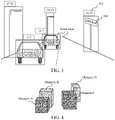
- An obstacle detection method provided in this application is performed by a computer device. Specifically, the method is applicable to an application environment shown in FIG. 1 .
- a target vehicle 102 communicates with a computer device 104 through a network.
- the target vehicle 102 acquires a road scene image of the road where the target vehicle is located, and uploads the acquired road scene image to the computer device 104.
- the computer device 104 performs obstacle recognition on the road scene image of the road where the target vehicle is located when acquiring the road scene image, to obtain region information and the depth-of-field information corresponding to each obstacle in the road scene image.
- the computer device 104 determines target obstacles in an occlusion relationship according to the region information corresponding to each obstacle, and determines a relative depth-of-field relationship between the target obstacles according to the depth-of-field information of the target obstacles.
- the computer device 104 acquires a ranging result of each obstacle collected by a ranging apparatus corresponding to the target vehicle, and determines, according to the relative depth-of-field relationship between the target obstacles and the ranging result of each obstacle, an obstacle detection result corresponding to the road where the target vehicle is located.
- the computer device 104 may deliver the obstacle detection result to the target vehicle 102, so that the target vehicle 102 avoids the obstacles in time according to the obstacle detection result.
- the target vehicle may be, but is not limited to, an autonomous vehicle.
- the computer device may be a terminal or a server.
- the terminal may be, but is not limited to, various personal computers, notebook computers, smart phones, tablet computers, and portable wearable devices.
- the server may be an independent physical server, a server cluster composed of a plurality of physical servers, a distributed system, or a cloud server that provides basic cloud computing services such as cloud storage, a network service, cloud communication, big data, and an artificial intelligence platform.
- the terminal and the server may be directly or indirectly connected through wired or wireless communication, which is not limited in this application.
- an obstacle detection method is provided.
- the method is applied to the computer device in FIG. 1 .
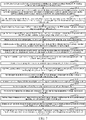
- Descriptions are made by using an example in which the computer device may be specifically a terminal or a server, including the following steps: S202: Acquire a road scene image of a road where a target vehicle is located.
- the road scene image is an image obtained by collecting scene information of the road.
- the road scene image can reflect a surrounding environment of the target vehicle, such as lanes and obstacles, including vehicles, pedestrians, street lights, traffic signs, and the like.
- the road scene image may be an image captured in real time by an image capture apparatus.
- the road scene image is analyzed in real time to obtain an obstacle detection result corresponding to the road where the target vehicle is located, so that the target vehicle can avoid obstacles in time based on the obstacle detection result.
- the computer device may receive road scene images uploaded by other computer devices to obtain the road scene image of the road where the target vehicle is located.
- the other computer devices may be the target vehicle or an image capture device associated with the target vehicle.
- the target vehicle When the target vehicle is in an automatic driving state, after capturing the real scene image by using the image capture apparatus to obtain the scene image of the road where the target vehicle is located, the target vehicle uploads the road scene image to the computer device, so that the computer device acquires the road scene image of the road where the target vehicle is located.
- the image capture apparatus may be a built-in image capture apparatus of the target vehicle, or may be an external image capture apparatus associated with the target vehicle.
- the target vehicle may be connected to an external image capture apparatus through a cable or a network.
- the image capture apparatus captures the image of the real scene, and transmits the captured image to the target vehicle.
- the built-in image capture apparatus may be a camera, and the external image capture apparatus associated with the target vehicle may be an image capture device carrying a camera, such as an unmanned aerial vehicle.
- the camera may be a monocular camera.
- the road scene image captured by the camera is a monocular image.
- the monocular image is a single image of a same scene, which may specifically be an RGB image.
- the camera is invoked to enable a scan mode, so as to scan in real time a target object in a field of view of the camera, and generate a road scene image in real time according to a specified frame rate.
- the field of view of the camera is a region where the camera can capture an image.
- S204 Perform obstacle recognition on the road scene image to obtain region information and depth-of-field information corresponding to each obstacle in the road scene image.
- the obstacle recognition means recognizing obstacles existing in the road scene image, including instance segmentation and depth-of-field prediction.
- Instance segmentation is a task of recognizing an outline of an object at a pixel level.
- the instance segmentation in this application means accurately segmenting obstacles of different classes in the road scene image, classifying all pixels in the image to determine a class of each pixel, so as to obtain a plurality of pixel regions, and distinguishing different obstacles in the pixel regions of a same class, so as to obtain region information corresponding to each obstacle in the road scene image.
- the depth-of-field prediction means predicting depth information of each obstacle in the road scene image, which may also be referred to as depth-of-field information.
- the depth-of-field information of the obstacle is a distance from the obstacle to the camera.
- the depth-of-field prediction specifically means predicting depth information of each pixel in the road scene image, and predicting the depth-of-field information corresponding to each obstacle based on the depth information of each pixel and the region information corresponding to each obstacle determined through the instance segmentation.
- FIG. 3 is a schematic diagram of an obstacle recognition result according to an embodiment. It can be seen that different obstacles correspond to different region information 302 and different depth information 304.
- the depth information is represented by a depth-of-field value obtained through the depth-of-field prediction.
- a smaller depth-of-field indicates a smaller distance from a corresponding obstacle to the target vehicle. That is to say, a relative magnitude of the depth-of-field value indicates a relative distance from the obstacle to the target vehicle.
- An obstacle recognition manner is not limited in the embodiments of this application, as long as the region information and the depth-of-field information corresponding to each obstacle can be obtained by performing obstacle recognition on the road scene image.
- a computer device performs obstacle recognition on the road scene image according to a pre-trained obstacle recognition model, to obtain the region information and the depth-of-field information corresponding to each obstacle in the road scene image.
- the pre-trained obstacle recognition model may include a convolutional neural network structure.
- the convolutional neural network may perform operations such as convolution calculation, normalization, and activation function calculation.
- a method for training an obstacle recognition model may be as follows: A training sample image and a training label corresponding to the training sample image are acquired. The training label is used for labeling a class to which each pixel in the corresponding training sample image belongs and corresponding depth-of-field information. Then parameters of the obstacle recognition model are initialized. The training sample image is input to the obstacle recognition model, to obtain predicted region information and predicted depth-of-field information corresponding to obstacles. Next, for a difference between the predicted region information and the predicted depth-of-field information and the training label, the parameters of the obstacle recognition model are optimized based on a gradient descent algorithm by using a loss function. The obstacle recognition model is iteratively trained according to the above method until a training stop condition is satisfied.
- the training stop condition may be that an iteration number reaches a specified number, or a variation of the loss function is less than a specified threshold.
- S206 Determine target obstacles in an occlusion relationship according to the region information corresponding to each obstacle, and determine a relative depth-of-field relationship between the target obstacles according to the depth-of-field information of the target obstacles.
- the target obstacles are those in the obstacles in the obtained road scene image in an occlusion relationship.
- the occlusion relationship indicates that corresponding region information of the target obstacles in the acquired road scene image intersects.
- the relative depth-of-field relationship indicates a distance of the target obstacle relative to the target vehicle. It may be understood that the distances between the target obstacles in an occlusion relationship and the target vehicle are different. That is to say, the depth-of-field information of each target obstacle is different. For example, if an obstacle A obscures an obstacle B, a distance from the obstacle A to the target vehicle is less than a distance from the obstacle B to the target vehicle. That is to say, compared with the obstacle B, the obstacle A is closer to the target vehicle. Relative distance relationships between different target obstacles and the target vehicle indicate the relative depth-of-field relationship between the target obstacles.
- the computer device performs obstacle recognition on the road scene image according to the pre-trained obstacle recognition model, to obtain the region information and the depth-of-field information corresponding to each obstacle in the road scene image, then determines whether the region information of different obstacles intersects based on the region information corresponding to each obstacle by using the obstacle recognition model, determines the obstacles corresponding to the region information intersecting each other as the target obstacles in an occlusion relationship, and determines relative distances from the target obstacles to the target vehicle according to the depth-of-field information of the target obstacles, to obtain the relative depth-of-field relationship between the target obstacles.
- the relative depth-of-field relationship between any two target obstacles may be expressed by a preset character. For example, “-1", “0", or “ 1” may be used to indicate the relative depth-of-field relationship between the target obstacles.
- the relative depth-of-field relationship between the obstacle A and the obstacle B is "-1 ", it indicates that the obstacle A obscures the obstacle B, which may be denoted as "(obstacle A, obstacle B, -1)".
- the relative depth-of-field relationship between the obstacle A and the obstacle B is "0"
- the relative depth-of-field relationship between the obstacle A and the obstacle B is "1" it indicates that the obstacle A is obscured by the obstacle B, which may be denoted as "(obstacle A, obstacle B, 1)".
- the relative depth-of-field relationship between two target obstacles is a smallest unit of the relative depth-of-field relationship between the target obstacles corresponding to the road scene image.
- the target obstacles in the road scene image shown in FIG. 4 include an obstacle A, an obstacle B, an obstacle C, and an obstacle D.
- a relative depth-of-field relationship between the target obstacles corresponding to the road scene image may be denoted as "(obstacle A, obstacle B, -1), (obstacle B, obstacle C, 0), and (obstacle C, obstacle D, 1)", indicating that the obstacle A obscures the obstacle B, there is no occlusion relationship between the obstacle B and the obstacle C, and the obstacle C obscures the obstacle D.
- S208 Acquire a ranging result of each obstacle collected by a ranging apparatus corresponding to the target vehicle.
- the ranging apparatus is an apparatus for measuring a distance from each obstacle to the target vehicle in a real scene.
- the real scene is a scene corresponding to the acquired road scene image.
- the ranging apparatus corresponding to the target vehicle may be integrated or installed on the target vehicle. This is not limited in this application.
- the ranging apparatus may be at least one of a camera or a radar.
- the camera may be a monocular camera, a binocular camera, a depth camera, a 3-dimensional (3 Dimensions, 3D) camera, or the like.
- the camera is invoked to enable a scan mode, so as to scan in real time a target object in a field of view of the camera, and generate, in real time according to a specified frame rate, ranging data for ranging.
- the ranging data may be specifically an obstacle image.
- the obstacle image may be a monocular image, a binocular image, a depth image, a 3 D image, or the like matching the ranging apparatus.
- the radar may be a radar system such as a lidar, a millimeter wave radar, or the like.
- the lidar is a radar system that detects feature data such as a position, a speed, an attitude, and a shape of a target object by emitting laser beams.
- the millimeter wave radar is a radar system that performs detection in a millimeter wave band.
- the radar system transmits a detection signal to the target object in real time, receives an echo signal reflected by the target object, and determines feature data of the target object based on a difference between the detection information and the echo signal.
- the radar system includes a plurality of transmitters and receivers, to obtain ranging data for ranging corresponding to the obstacles in the real scene.
- the ranging data may be specifically 3D point cloud data.
- the target vehicle may determine an estimated distance from each obstacle to the target vehicle based on the obtained ranging data, that is, obtain a ranging result of each obstacle, and upload the ranging result to the computer device, so that the computer device acquires the ranging result of each obstacle collected by the capture apparatus corresponding to the target vehicle.
- the target vehicle uploads the ranging data to the computer device.
- the computer device determines the estimated distance from each obstacle to the target vehicle based on the ranging data, so as to obtain the ranging result of each obstacle.
- the distance prediction model is a neural network model, including a monocular single-frame ranging model, a monocular multi-frame ranging model, a binocular stereo vision ranging model, a radar target detection and ranging model, a radar-monocular image fused ranging model, or the like.
- a monocular single-frame ranging method may be used to estimate the distance from the obstacle in the single-frame monocular image to the target vehicle, to obtain the ranging result.
- a monocular multi-frame ranging method may be used to estimate the distance from the obstacle in the multi-frame monocular image to the target vehicle, to obtain the ranging result.
- a binocular stereo vision ranging method may be used to estimate the distance from the obstacle in the binocular image to the target vehicle, to obtain the ranging result.
- the ranging data is 3D point cloud data collected by a radar
- a radar target detection and ranging algorithm is used to predict the distance from the target obstacle corresponding to the 3D point cloud data to the target vehicle based on the collected 3D point cloud data, to obtain the ranging result.
- the ranging data includes a monocular image captured by the monocular camera and the 3D point cloud data collected by the radar
- a radar-monocular image fused target detection and ranging algorithm is used to estimate the distance from the obstacle in the monocular image to the target vehicle based on the captured monocular image and the collected 3D point cloud data, to obtain the ranging result.
- S210 Determine, according to the relative depth-of-field relationship between the target obstacles and the ranging result of each obstacle, an obstacle detection result corresponding to the road where the target vehicle is located.
- the obstacle detection result may reflect the relative distance relationship between the obstacle corresponding to the road scene image and the target vehicle.
- the obstacle detection result is at least one of the relative depth-of-field relationship between the target obstacles, the ranging result of each obstacle, or a hazard level of each obstacle.
- the hazard level is a representation of a degree of hazard of the obstacle relative to the target vehicle. In a practical application scenario, the target vehicle needs to preferentially avoid the target obstacle with a higher hazard level.
- S210 includes: determining the hazard level of each obstacle according to the ranging result of each obstacle and the relative depth-of-field relationship between the target obstacles in the obstacles, and determining at least one of the relative depth-of-field relationship between the target obstacles, the ranging result of each obstacle, or the hazard level of each obstacle as the obstacle detection result corresponding to the road where the target vehicle is located.
- the hazard level of the target obstacle in any two target obstacles in an occlusion relationship that is obscured is lower than the hazard level of the target obstacle in the foreground. That is to say, the target obstacle in the two target obstacles in an occlusion relationship that is closer to the target vehicle has a higher hazard level.
- the determining, by the computer device, a hazard level of each obstacle according to the ranging result of each obstacle and the relative depth-of-field relationship between the target obstacles in the obstacles includes: determining an original hazard level corresponding to each obstacle according to the ranging result of each obstacle; correcting the original hazard levels of the target obstacles based on the relative depth-of-field relationship between the target obstacles in the obstacles, so as to obtain corresponding corrected hazard levels; and determining, according to the unadjusted original hazard levels of the obstacles and the corrected hazard levels of the target obstacles, a hazard level corresponding to each obstacle on the road where the target vehicle is located.
- the original hazard level matches the ranging result. It may be understood that an obstacle closer to the target vehicle means a higher hazard level to the target vehicle, that is, a higher original hazard level.
- the computer device determines distance intervals of the obstacles according to the ranging result of the obstacles from the target vehicle, acquires an original hazard level matching each distance interval, determines the original hazard levels as the original hazard levels of the obstacles, determines relative concern levels of the target obstacles based on the relative depth-of-field relationship between the target obstacles in the obstacles, corrects the original hazard levels of the target obstacles based on the relative concern levels to obtain corresponding corrected hazard levels, and determines the unadjusted original hazard levels of the obstacles and the corrected hazard levels of the target obstacles as the hazard levels respectively corresponding to the obstacles on the road where the target vehicle is located.
- the original hazard level matching the distance interval may be changed according to a changed travelling scene of the target vehicle.
- the travelling scene of the target vehicle includes a road scene and a weather scene.
- the road scene may be a common urban road, a bustling street, a highway, and the like, and the weather scene includes a sunny day, rainy and snowy days, a foggy day, and the like.
- the relative concern level of the target obstacle is concern levels of the target obstacles in an occlusion relationship relative to each other. For example, if the obstacle A obscures the obstacle B, the relative concern level of the obstacle A is a high concern level, and the relative concern level of the obstacle B is a low concern level.
- a specific manner of correcting the original hazard levels of the target obstacles based on the relative concern levels may be as follows: When the original hazard level matches the relative concern level, the original hazard level is determined as the corrected hazard level, and the original hazard level does not match the relative concern level, the original hazard level is corrected to a hazard level matching the relative concern level, and the hazard level matching the relative concern level is the corrected hazard level.
- an original hazard level of a detected obstacle at a distance less than 10 m from the target vehicle is determined as the high original hazard level (denoted as high), and an original hazard level of a detected obstacle at a distance greater than or equal to 10 m and less than 30 m from the target vehicle is determined as a medium original hazard level (denoted as medium), and an original hazard level of a detected obstacle at a distance greater than or equal to 30 m from the target vehicle is determined as a low original hazard level (denoted as low).
- the distances between the detected obstacles A and B to the target vehicle are both less than 10 m, the obstacles A and B are in an occlusion relationship, and a corresponding relative depth-of-field relationship is "(obstacle A, obstacle B, -1)". Therefore, it is determined that the original hazard levels of the obstacle A and the obstacle B are both the high original hazard level (denoted as high), and it is determined that the relative concern level of the obstacle A is the high concern level (denoted as high) and the relative concern level of the obstacle B is the low concern level (denoted as low).
- the high original hazard level of the obstacle A is not changed
- the original hazard level of the obstacle B is corrected from the high original hazard level to the low hazard level
- the original hazard levels of the detected obstacles other than the obstacle A and the obstacle B and the corrected hazard levels of the obstacle A and the obstacle B are determined as the hazard levels respectively corresponding to the obstacles on the road where the target vehicle is located.
- the computer device performs obstacle recognition on the acquired road scene image to obtain the region information and the depth-of-field information corresponding to each obstacle in the road scene image of the road where the target vehicle is located, determines the target obstacles in an occlusion relationship according to the region information corresponding to each obstacle, and determines the relative depth-of-field relationship between the target obstacles according to the depth-of-field information of the target obstacles.
- the obstacle detection result corresponding to the road where the target vehicle is located can still be accurately determined according to the relative depth-of-field relationship between the target obstacles and the ranging result of each obstacle, so that the obstacle with a relatively high hazard level can be avoided in time based on the accurate the obstacle detection result, thereby improving safety and reliability of automatic driving.
- This application further provides an application scenario where the above obstacle detection method is applied.
- the application of the obstacle detection method in this application scenario is as follows:
- the computer device After acquiring the road scene image of the road where the target vehicle is located, the computer device performs obstacle recognition on the road scene image by using the obstacle recognition model to obtain the region information and the depth-of-field information corresponding to each obstacle in the road scene image, and determines the relative depth-of-field relationship between the target obstacles in the obstacles in an occlusion relationship according to the region information corresponding to each obstacle.
- the computer device further receives the 3D point cloud data collected by the target vehicle through the radar, projects the 3D point cloud data to an image coordinate system to obtain a point cloud image, obtains the ranging result of each obstacle based on the point cloud image, that is, obtains the distance from each obstacle to the target vehicle, determines the original hazard level (including low, medium, and high) corresponding to each obstacle according to the distance, corrects the original hazard levels of the target obstacles in the obstacles according to the relative depth-of-field relationship between the target obstacles, to obtain the corrected hazard level of each target obstacle, determines the uncorrected original hazard levels of the obstacles and the corrected hazard levels of the target obstacle as the hazard levels of the target obstacles, and then outputs the ranging result of each obstacle, the relative depth-of-field relationship of the target obstacles, and the hazard level of each obstacle as the obstacle detection result, that is, outputs a 3 D physical distance, the depth-of-field relationship, and the hazard level of the obstacle.
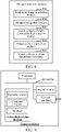
- S204 specifically includes the following steps.
- S502 Input the road scene image to an obstacle recognition model, the obstacle recognition model including a feature extraction network, an instance segmentation network, and a depth-of-field prediction network.
- the obstacle recognition model is a neural network model, which may specifically include a convolutional neural network structure.
- the convolutional neural network may perform operations such as convolution calculation, normalization, and activation function calculation.
- S504 Perform feature extraction on the road scene image by using the feature extraction network to obtain a plurality of feature maps corresponding to different scales.
- the feature extraction network is configured to perform feature extraction on the road scene image.
- the feature extraction network may include a feature extraction backbone network (Backbone) and a feature pyramid network (FPN).
- Backbone feature extraction backbone network
- FPN feature pyramid network
- the computer device inputs the road scene image to the feature extraction backbone network for processing by convolutional network layers of different scales in the feature extraction backbone network, to obtain a plurality of backbone feature maps corresponding to different scales; and inputs the backbone feature maps of different scales to the FPN for processing by the FPN, to obtain a plurality of feature maps corresponding to different scales.
- the FPN includes a plurality of upsampling modules. Each upsampling module is composed of an upsampling network layer, a normalization layer, and an activation layer. A number of upsampling modules is the same as a number of backbone feature maps of different scales extracted by the feature extraction backbone network.
- the convolutional network layers of different scales mean image sizes of the feature maps outputted by the convolutional network layers are different.
- the computer device inputs the plurality of backbone feature maps of different scales to the FPN, performs upsampling on each inputted backbone feature map by using the upsampling module of the FPN to amplify the backbone feature map, to obtain an amplified backbone feature map, and fuses the amplified backbone feature map with an input target backbone feature map to obtain a fused feature map of a corresponding scale, the target backbone feature map being a backbone feature map with a same scale as the amplified backbone feature map, thereby obtaining the plurality of feature maps corresponding to different scales.
- S506 Perform instance segmentation on the feature maps of different scales by using the instance segmentation network, to obtain the region information corresponding to each obstacle in the road scene image.
- the instance segmentation network is configured to perform instance segmentation on the obstacles in the road scene image, and specifically includes a region proposal network (RPN), a target classification network, and a target segmentation network.
- RPN region proposal network
- target classification network a target classification network
- target segmentation network a target segmentation network
- the computer device inputs the feature maps of different scales to the RPN for processing by a convolutional network layer of a preset scale in the RPN, to obtain candidate regions corresponding to the feature maps; predicts an obstacle class corresponding to each of the candidate regions by using the target classification network; and performs instance segmentation on the candidate regions based on the predicted obstacle classes to which the candidate regions belong, to obtain region information corresponding to each obstacle.
- the preset scale may include a plurality of different sizes, for example, the preset scale includes 3 ⁇ 3 and 1 ⁇ 1.
- a plurality of candidate boxes can be generated. A region included in each candidate box is the candidate region, so that the candidate region corresponding to each feature map is obtained.
- the feature map parts corresponding to the candidate regions are inputted to the target classification network by using a regional feature aggregation module (ROI Align), so as to classify the obstacles corresponding to the candidate regions by using the target classification network, to obtain the obstacle class corresponding to each candidate region, and the candidate region belonging to the obstacle class is inputted to the target segmentation network, to obtain the region information of the obstacle from the candidate region by using the target segmentation network.
- ROI Align regional feature aggregation module
- S508 Perform depth-of-field prediction on each obstacle based on the region information corresponding to each obstacle by using the depth-of-field prediction network, to obtain the depth-of-field information corresponding to each obstacle.
- the depth-of-field prediction network is configured to predict the depth-of-field information of each obstacle in the road scene image.
- the depth-of-field prediction network may be further configured to determine target obstacles in an occlusion relationship according to the region information corresponding to each obstacle, and determine relative depth-of-field information of the target obstacles according to the depth-of-field information of the target obstacles.
- the computer device predicts depth information of each pixel in the road scene image by using the depth-of-field prediction network, and predicts the depth-of-field information corresponding to each obstacle based on the depth information of each pixel and the region information corresponding to each obstacle determined through the instance segmentation.
- FIG. 6 is a schematic structural diagram of an obstacle recognition model according to an embodiment. It may be seen that the obstacle recognition model includes a feature extraction network, an instance segmentation network, and a depth-of-field prediction network (Relation Aware Head).
- the obstacle recognition model includes a feature extraction network, an instance segmentation network, and a depth-of-field prediction network (Relation Aware Head).
- the feature extraction network includes a feature extraction backbone network (Backbone) and an FPN.
- the instance segmentation network includes an RPN, a target classification network (Box head) and a target segmentation network (Mask head).
- the feature extraction backbone network (Backbone) includes convolution modules of different scales.
- Each convolution module includes a convolutional (Convolution) network layer a normalization layer (batch normalization, BN) and an activation layer (Relu).
- the FPN includes a plurality of upsampling modules.
- Each upsampling module is composed of an upsampling network layer (bilinear upsampling), a normalization layer, and an activation layer.
- a number of upsampling modules is the same as a number of backbone feature maps of different scales extracted by the feature extraction backbone network.
- the instance segmentation network includes an RPN, a target classification network (Box head) and a target segmentation network (Mask head).
- the RPN includes a plurality of convolution modules of a preset scale configured to extract candidate regions from the feature maps of different scales.
- the target classification network (Box head) includes a convolution module and a fully connected module, and is configured to predict a class of each candidate region and a candidate box position corresponding to each candidate region.
- the target segmentation network (Mask head) includes a plurality of convolution modules configured to perform non-linear transform on the candidate region to achieve instance segmentation of the obstacle.
- the depth-of-field prediction network includes convolution modules of different scales and a downsampling module, and is configured to predict the depth-of-field information of the obstacle corresponding to each candidate region, and determine the relative depth-of-field relationship between the target obstacles in an occlusion relationship.
- the feature extraction backbone network includes four convolution modules of different scales.
- An RGB image of W ⁇ H ⁇ C (W represents a length of the image, H represents a width of the image, and C represents a number of channels of the image) is inputted to the feature extraction backbone network.
- An image area of an image outputted by each convolution module is 1/4 of an image area of the inputted image, so that four backbone feature maps of different scales are obtained.
- the obtained four feature maps of different scales are inputted to the FPN.
- the FPN After obtaining the amplified backbone feature map, the FPN fuses the amplified backbone feature map with an input target backbone feature map to obtain four fused feature maps of different scales.
- the downsampling module of the FPN performs downsampling on the one of the four backbone feature maps of different scales that has a smallest scale to obtain a feature map of a new scale, thereby obtaining five feature maps of different scales by using the FPN.
- the RPN extracts candidate regions from the five feature maps of different scales and inputs the feature map parts corresponding to the candidate regions to the target classification network (Box head) by using the regional feature aggregation module (ROI align), outputs a to-be-detected-obstacle class if the candidate regions belong to the obstacle class, returns to a candidate box position (boundbox), and inputs the candidate regions to the target segmentation network (Mask head).
- the target segmentation network (Mask head) classifies the candidate regions into two classes: foreground and background, the foreground being an obstacle region, so as to extract the region information (Mask) of the obstacle, and uses the obstacle class outputted by the target classification network (Box head) as the obstacle class corresponding to the region information.
- a feature fusion module (concat) and a maximum pooling module (max polling) input a result of instance segmentation (that is, silent information of the obstacles and the obstacle class) to the depth-of-field prediction network (Relation Aware Head).
- the depth-of-field prediction network (Relation Aware Head) performs depth-of-field prediction on each obstacle based on the region information corresponding to each obstacle, and outputs a depth-of-field value corresponding to each obstacle.
- the computer device inputs the road scene image to the obstacle recognition model, the obstacle recognition model including the feature extraction network, the instance segmentation network, and the depth-of-field prediction network, performs feature extraction on the road scene image by using the feature extraction network to obtain the plurality of feature maps corresponding to different scales, and performs instance segmentation on the feature maps of different scales by using the instance segmentation network, to obtain the region information corresponding to each obstacle in the road scene image. Therefore, the region information can be accurately extracted for the obstacles of different scales in the road scene image, and depth-of-field prediction can be performed on each obstacle based on the region information corresponding to each obstacle by using the depth-of-field prediction network, so as to obtain the depth-of-field information corresponding to each obstacle. In this way, accurate acquisition of the region information and the depth information of the obstacles of different scales in road scene images is realized, thereby improving accuracy of obstacle detection.
- the step in which the computer device determines the target obstacles in an occlusion relationship according to the region information corresponding to each obstacle includes: acquiring a candidate region corresponding to each obstacle based on the region information corresponding to each obstacle during the obstacle recognition; calculating an overlapping ratio between the candidate regions corresponding to different obstacles; and determining, as the target obstacles in an occlusion relationship, the obstacles corresponding to the candidate regions with an overlapping ratio greater than an overlapping ratio threshold.
- the computer device obtains the candidate box corresponding to the candidate region when extracting the candidate region by using the RPN in the instance segmentation network, specifically, obtains a size and coordinates of the candidate box.
- the computer device determines the candidate region corresponding to each obstacle according to the region information corresponding to each obstacle, specifically, determines a candidate box corresponding to each obstacle, calculates an overlapping ratio between the candidate boxes corresponding to different obstacles based on sizes and coordinates of the candidate boxes, and determines, as the target obstacles in an occlusion relationship, the obstacles corresponding to the candidate regions with an overlapping ratio greater than an overlapping ratio threshold.
- the overlapping ratio threshold may be set according to an actual application scenario.
- the computer device acquires the candidate region corresponding to each obstacle based on the region information corresponding to each obstacle during the obstacle recognition, and calculates the overlapping ratio between the candidate regions corresponding to different obstacles, so that the target obstacles in an occlusion relationship can be determined based on the overlapping ratio between the candidate regions corresponding to the obstacles, and determination of the relative depth-of-field relationship between the target obstacles can be realized, thereby improving the accuracy of obstacle detection.
- the step in which the computer device determines the relative depth-of-field relationship between the target obstacles according to the depth-of-field information of the target obstacles includes: sorting the target obstacles by distance based on the depth-of-field information of the target obstacles, to obtain a corresponding depth-of-field sorting result; and determining the relative depth-of-field relationship between the target obstacles based on the depth-of-field sorting result.
- the depth-of-field information of each obstacle obtained by the computer device is a depth-of-field value.
- a magnitude of the depth-of-field value indicates a distance from the obstacle to the target vehicle. For example, a smaller depth-of-field value indicates a smaller distance from the obstacle to the target vehicle, and a larger depth-of-field value indicates a larger distance from the obstacle to the target vehicle.
- the computer device sorts the target obstacles based on the depth-of-field information of the target obstacles. Specifically, the computer device sorts the target obstacles according to the magnitudes of the depth-of-field values, to obtain the depth-of-field sorting result of the target obstacles.
- the computer device may express the relative depth-of-field relationship between any two target obstacles by a preset character. For example, “-1", "0", or "1" is used to indicate the relative depth-of-field relationship between the target obstacles.
- the computer device sorts the target obstacles based on the depth-of-field information of the target obstacles, to obtain the corresponding depth-of-field sorting result, and determines the relative depth-of-field relationship between the target obstacles based on the depth-of-field sorting result, and therefore accurately determines the obstacle detection result corresponding to the road where the target vehicle is located, thereby improving the accuracy of obstacle detection.
- the ranging apparatus includes at least one of a camera or a radar.
- the ranging result of each obstacle is determined in different manners based on the ranging data.
- a distance prediction model matching the ranging apparatus may be used to obtain the ranging result of each obstacle based on the ranging data.
- the data preprocessing manner matching the distance prediction model means the data preprocessing manner matching the ranging apparatus.
- the data preprocessing manner includes an image preprocessing manner or a point cloud data preprocessing manner.
- the image preprocessing manner may be at least one of image graying, geometric transformation, or image augmentation, and the point cloud data preprocessing may mean projecting point cloud data to a coordinate system to obtain a point cloud image.
- the ranging data is a monocular or binocular image captured by a camera
- the captured monocular or binocular image may be preprocessed in the image preprocessing manner to obtain a preprocessed monocular or binocular image.
- the collected image data is 3D point cloud data
- the 3D point cloud data may be preprocessed in the point cloud data preprocessing manner to obtain a point cloud image.
- the computer device acquires the ranging data collected by the ranging apparatus corresponding to the target vehicle, preprocesses the ranging data in the data preprocessing manner matching the ranging apparatus to obtain the preprocessed ranging data, and performs distance estimation on the preprocessed ranging data by using the distance prediction model matching the ranging apparatus, to obtain the ranging result of each obstacle, thereby improving the accuracy of obstacle detection.
- an obstacle detection method is further provided.
- the method is applied to the computer device 104 in FIG. 1 , for example.
- the method includes the following steps:
- This application further provides an application scenario where the above obstacle detection method is applied.
- the application of the obstacle detection method in this application scenario is as follows: During travelling of the target vehicle in the automatic driving state, the road scene image (which is a monocular image) of the road where the target vehicle is located is captured by using a monocular camera, and the road scene image is transmitted to a computer device.
- the road scene image can reflect a surrounding environment of the target vehicle, such as lanes and obstacles, including vehicles, pedestrians, street lights, traffic signs, and the like.
- 3D point cloud data of each obstacle on the road where the target vehicle is located is collected by using a radar, and the 3D point cloud data is transmitted to the computer device.
- the obstacle recognition model includes a feature extraction network, an instance segmentation network and a depth-of-field prediction network (Relation Aware Head).
- the feature extraction network includes a feature extraction backbone network (Backbone) and an FPN.
- the instance segmentation network includes an RPN, a target classification network (Box head) and a target segmentation network (Mask head).
- the plurality of backbone feature maps corresponding to different scales are obtained, and the backbone feature maps of different scales are inputted to the FPN for processing by the upsampling module and the downsampling module in the FPN, to obtain the plurality of feature maps corresponding to different scales, and the feature maps of different scales are inputted to the RPN for processing by the convolutional network layer of the preset scale in the RPN, to obtain the candidate region corresponding to each feature map, and the obstacle class corresponding to each candidate region is predicted by using the target classification network.
- Instance segmentation is performed on the candidate region based on the predicted obstacle class to which each candidate region belongs, to obtain the region information (mask) corresponding to each obstacle.
- Depth-of-field prediction is performed on each obstacle based on the region information corresponding to each obstacle by using the depth-of-field prediction network, to obtain the depth-of-field information corresponding to each obstacle, and a candidate region (a candidate box) corresponding to each obstacle is acquired based on the region information (mask) corresponding to each obstacle by using the depth-of-field prediction network during the obstacle recognition.
- the target obstacles in an occlusion relationship are determined based on the candidate regions, and depths of field of the target obstacles are sorted according to the predicted depth-of-field information of each obstacle, to obtain a depth-of-field sorting relationship between the target obstacles (that is, the relative depth-of-field relationship).
- the computer device After acquiring the 3D point cloud data of the obstacles on the road where the target vehicle is located, the computer device projects the 3D point cloud data to an image coordinate system to obtain a point cloud image, determines a distance from each obstacle to the target vehicle based on the point cloud image, and determines the original hazard level of each obstacle based on the distance from the target vehicle.
- the computer device After obtaining the depth-of-field sorting relationship between the target obstacles in the road scene image, the computer device corrects the original hazard levels of the target obstacles in the obstacles based on the depth-of-field sorting relationship, to obtain the corrected hazard levels of the target obstacles, and determines the uncorrected original hazard levels of the obstacles and the corrected hazard levels of the target obstacle as the hazard levels of the target obstacles.
- the target obstacle is obscured by other obstacles, it is determined that the corrected hazard level of the target obstacle is low. If the original hazard level of the target obstacle does not match the depth-of-field sorting result, the original hazard level of the obstacle is corrected based on the depth-of-field sorting result.
- the computer device After obtaining the hazard level of each obstacle, the computer device outputs the distance from each obstacle to the target vehicle, the depth-of-field sorting relationship between the obstacles, and the concern level of each obstacle as the obstacle detection result.
- FIG. 2 , FIG. 5 , and FIG. 7 are sequentially shown according to indication of an arrow, the steps are not necessarily sequentially performed according to a sequence indicated by the arrow. Unless clearly specified in this specification, there is no strict sequence limitation on the execution of the steps, and the steps may be performed in another sequence.
- at least some steps in FIG. 2 , FIG. 5 , and FIG. 7 may include a plurality of steps or a plurality of stages. The steps or the stages are not necessarily performed at the same moment, but may be performed at different moments. The steps or the stages are not necessarily performed in sequence, but may be performed in turn or alternately with another step or at least some of steps or stages of the another step.
- an obstacle detection apparatus which may be a software module, a hardware module, or a combination thereof to be incorporated as a part of a computer device.
- the apparatus specifically includes: a road scene image acquisition module 802, an obstacle recognition module 804, a relative depth-of-field relationship determination module 806, a ranging result acquisition module 808, and an obstacle detection result determination module 810.
- the road scene image acquisition module 802 is configured to acquire a road scene image of a road where a target vehicle is located.
- the obstacle recognition module 804 is configured to perform obstacle recognition on the road scene image to obtain region information and depth-of-field information corresponding to each obstacle in the road scene image.
- the relative depth-of-field relationship determination module 806 is configured to: determine target obstacles in an occlusion relationship according to the region information corresponding to each obstacle, and determine a relative depth-of-field relationship between the target obstacles according to the depth-of-field information of the target obstacles.
- the ranging result acquisition module 808 is configured to acquire a ranging result of each obstacle collected by a ranging apparatus corresponding to target vehicle.
- the obstacle detection result determination module 810 is configured to determine, according to the relative depth-of-field relationship between the target obstacles and the ranging result of each obstacle, an obstacle detection result corresponding to the road where the target vehicle is located.
- the road scene image acquisition module 802 is further configured to receive, in a case that the target vehicle is in an automatic driving state, a road scene image transmitted by an image capture apparatus corresponding to the target vehicle, the road scene image being an image of a real scene of the road where the target vehicle is located captured by the image capture apparatus.
- the obstacle detection result determination module 810 is further configured to: determine a hazard level of each obstacle according to the ranging result of each obstacle and the relative depth-of-field relationship between the target obstacles in the obstacles; and determine at least one of the relative depth-of-field relationship between the target obstacles, the ranging result of each obstacle, or the hazard level of each obstacle as the obstacle detection result corresponding to the road where the target vehicle is located.
- the obstacle detection result determination module 810 is further configured to: determine an original hazard level corresponding to each obstacle according to the ranging result of each obstacle; correct the original hazard levels of the target obstacles based on the relative depth-of-field relationship between the target obstacles in the obstacles, so as to obtain corresponding corrected hazard levels; and determine, according to the unadjusted original hazard levels of the obstacles and the corrected hazard levels of the target obstacles, a hazard level corresponding to each obstacle on the road where the target vehicle is located.
- obstacle recognition is performed on the acquired road scene image to obtain the region information and the depth-of-field information corresponding to each obstacle in the road scene image of the road where the target vehicle is located, the target obstacles in an occlusion relationship are determined according to the region information corresponding to each obstacle, and the relative depth-of-field relationship between the target obstacles is determined according to the depth-of-field information of the target obstacles.
- the obstacle detection result corresponding to the road where the target vehicle is located can still be accurately determined according to the relative depth-of-field relationship between the target obstacles and the ranging result of each obstacle, so that the obstacle with a relatively high hazard level can be avoided in time based on the accurate the obstacle detection result, thereby improving safety and reliability of automatic driving.
- the obstacle recognition module 804 is further configured to: input the road scene image to an obstacle recognition model, the obstacle recognition model including a feature extraction network, an instance segmentation network, and a depth-of-field prediction network; perform feature extraction on the road scene image by using the feature extraction network to obtain a plurality of feature maps corresponding to different scales; perform instance segmentation on the feature maps of different scales by using the instance segmentation network, to obtain the region information corresponding to each obstacle in the road scene image; and perform depth-of-field prediction on each obstacle based on the region information corresponding to each obstacle by using the depth-of-field prediction network, to obtain the depth-of-field information corresponding to each obstacle.
- the obstacle recognition model including a feature extraction network, an instance segmentation network, and a depth-of-field prediction network
- perform instance segmentation on the feature maps of different scales by using the instance segmentation network to obtain the region information corresponding to each obstacle
- the feature extraction network includes a feature extraction backbone network and an FPN
- the obstacle recognition module 804 is further configured to: input the road scene image to the feature extraction backbone network for processing by convolutional network layers of different scales in the feature extraction backbone network, to obtain a plurality of backbone feature maps corresponding to different scales; input the backbone feature maps of different scales to the FPN for processing by the FPN, to obtain a plurality of feature maps corresponding to different scales after.
- the instance segmentation network includes an RPN, a target classification network, and a target segmentation network
- the obstacle recognition module 804 is further configured to: input the feature maps of different scales to the RPN for processing by a convolutional network layer of a preset scale in the RPN, to obtain candidate regions corresponding to the feature maps; predict an obstacle class corresponding to each of the candidate regions by using the target classification network; and perform instance segmentation on the candidate regions based on the predicted obstacle classes to which the candidate regions belong, to obtain region information corresponding to each obstacle.
- the road scene image is inputted to the obstacle recognition model, the obstacle recognition model including the feature extraction network, the instance segmentation network, and the depth-of-field prediction network, feature extraction is performed on the road scene image by using the feature extraction network to obtain the plurality of feature maps corresponding to different scales, and instance segmentation is performed on the feature maps of different scales by using the instance segmentation network, to obtain the region information corresponding to each obstacle in the road scene image. Therefore, the region information can be accurately extracted for the obstacles of different scales in the road scene image, and depth-of-field prediction can be performed on each obstacle based on the region information corresponding to each obstacle by using the depth-of-field prediction network, so as to obtain the depth-of-field information corresponding to each obstacle. In this way, accurate acquisition of the region information and the depth information of the obstacles of different scales in road scene images is realized, thereby improving accuracy of obstacle detection.
- the relative depth-of-field relationship determination module 806 is further configured to: acquire a candidate region corresponding to each obstacle based on the region information corresponding to each obstacle during the obstacle recognition; calculate an overlapping ratio between the candidate regions corresponding to different obstacles; and determine, as target obstacles in an occlusion relationship, the obstacles corresponding to the candidate regions with an overlapping ratio greater than an overlapping ratio threshold.
- the candidate region corresponding to each obstacle is acquired based on the region information corresponding to each obstacle during the obstacle recognition, and the overlapping ratio between the candidate regions corresponding to different obstacles is calculated, so that the target obstacles in an occlusion relationship can be determined based on the overlapping ratio between the candidate regions corresponding to the obstacles, and determination of the relative depth-of-field relationship between the target obstacles can be realized, thereby improving the accuracy of obstacle detection.
- the relative depth-of-field relationship determination module 806 is further configured to: sort the target obstacles by distance based on the depth-of-field information of the target obstacles, to obtain a corresponding depth-of-field sorting result; and determine the relative depth-of-field relationship between the target obstacles based on the depth-of-field sorting result.
- the target obstacles are sorted based on the depth-of-field information of the target obstacles, to obtain the corresponding depth-of-field sorting result, and the relative depth-of-field relationship between the target obstacles is determined based on the depth-of-field sorting result, and therefore the obstacle detection result corresponding to the road where the target vehicle is located is accurately determined, thereby improving the accuracy of obstacle detection.
- the ranging apparatus includes at least one of a camera or a radar
- the ranging result acquisition module 808 is further configured to: acquire ranging data collected by the ranging apparatus corresponding to the target vehicle; preprocess the ranging data in a data preprocessing manner matching the ranging apparatus, to obtain preprocessed ranging data; and perform distance estimation on the preprocessed ranging data by using a distance prediction model matching the ranging apparatus, to obtain the ranging result of each obstacle.
- the ranging data collected by the ranging apparatus corresponding to the target vehicle is acquired, the ranging data in the data preprocessing manner matching the ranging apparatus is preprocessed to obtain the preprocessed ranging data, and distance estimation is performed on the preprocessed ranging data by using the distance prediction model matching the ranging apparatus, to obtain the ranging result of each obstacle, thereby improving the accuracy of obstacle detection.
- the modules in the foregoing obstacle detection apparatus may be implemented entirely or partially by software, hardware, or a combination thereof.
- the foregoing modules may be built in or independent of a processor of a computer device in a hardware form, or may be stored in a memory of the computer device in a software form, so that the processor invokes and performs an operation corresponding to each of the foregoing modules.
- a computer device is provided.
- the computer device may be a server, and an internal structure diagram thereof may be shown in FIG. 9 .
- the computer device includes a processor, a memory, and a network interface connected through a system bus.
- the processor of the computer device is configured to provide computing and control capabilities.
- the memory of the computer device includes a non-volatile storage medium and an internal memory.
- the non-volatile storage medium stores an operating system, a computer program, and a database.
- the internal memory provides an environment for running of the operating system and the computer programs in the non-volatile storage medium.
- the database of the computer device is configured to store data of a road scene image.
- the network interface of the computer device is configured to communicate with an external terminal through a network connection.
- the computer program is executed by the processor to implement an obstacle detection method.
- a computer device is provided.
- the computer device may be a terminal, and an internal structure diagram thereof may be shown in FIG. 10 .
- the computer device includes a processor, a memory, a communication interface, a display screen, and an input apparatus that are connected by using a system bus.
- the processor of the computer device is configured to provide computing and control capabilities.
- the memory of the computer device includes a non-volatile storage medium and an internal memory.
- the non-volatile storage medium stores an operating system and a computer program.
- the internal memory provides an environment for running of the operating system and the computer programs in the non-volatile storage medium.
- the communication interface of the computer device is used for wired or wireless communication with an external terminal.
- the wireless communication may be realized by Wi-Fi, an operator network, near field communication (NFC), or other technologies.
- the computer program is executed by the processor to implement an obstacle detection method.
- the display screen of the computer device may be a liquid crystal display screen or an electronic ink display screen.
- the input apparatus of the computer device may be a touch layer covering the display screen, or may be a key, a trackball, or a touch pad disposed on a housing of the computer device, or may be an external keyboard, a touch pad, a mouse, or the like.
- FIG. 9 or FIG. 10 is only a block diagram of a partial structure related to the solution of this application, and does not limit the computer device to which the solution of this application is applied.
- the computer device may include more or fewer components than those shown in the figure, or some components may be combined, or a different component deployment is used.
- a computer device including a memory and one or more processors, the memory storing computer-readable instructions, the computer-readable instructions, when executed by the one or more processors, causing the one or more processors to perform the steps of the foregoing method embodiments.
- one or more non-volatile readable storage media storing computer-readable instructions are provided, the computer-readable instructions, when executed by one or more processors, causing the one or more processors to perform the steps of the foregoing method embodiments.
- a computer program product or a computer program is provided, the computer program product or the computer program including computer instructions, the computer instructions being stored in a computer-readable storage medium.
- a processor of a computer device reads the computer instructions from the computer-readable storage medium and executes the computer instructions to cause the computer device to perform the steps of the foregoing method embodiments.
- any reference to a memory, a storage, a database, or another medium used in the embodiments provided in this application may include at least one of a non-volatile memory and a volatile memory.
- the non-volatile memory may include a read-only memory (ROM), a hard disk, a flash memory, and an optical memory.
- the volatile memory may include a random access memory (RAM) or an external high-speed cache.
- the RAM is available in a plurality of forms, such as a static RAM (SRAM), a dynamic RAM (DRAM), or the like.
Landscapes
- Engineering & Computer Science (AREA)
- Theoretical Computer Science (AREA)
- Physics & Mathematics (AREA)
- General Physics & Mathematics (AREA)
- Multimedia (AREA)
- Computer Vision & Pattern Recognition (AREA)
- Evolutionary Computation (AREA)
- Data Mining & Analysis (AREA)
- Artificial Intelligence (AREA)
- Software Systems (AREA)
- Computing Systems (AREA)
- General Health & Medical Sciences (AREA)
- Health & Medical Sciences (AREA)
- Life Sciences & Earth Sciences (AREA)
- General Engineering & Computer Science (AREA)
- Medical Informatics (AREA)
- Databases & Information Systems (AREA)
- Bioinformatics & Cheminformatics (AREA)
- Radar, Positioning & Navigation (AREA)
- Evolutionary Biology (AREA)
- Bioinformatics & Computational Biology (AREA)
- Remote Sensing (AREA)
- Biomedical Technology (AREA)
- Mathematical Physics (AREA)
- Computational Linguistics (AREA)
- Biophysics (AREA)
- Molecular Biology (AREA)
- Electromagnetism (AREA)
- Aviation & Aerospace Engineering (AREA)
- Automation & Control Theory (AREA)
- Traffic Control Systems (AREA)
- Image Analysis (AREA)
Abstract
Description
- This application claims priority to
Chinese Patent Application No. 2020111386275, entitled "OBSTACLE DETECTION METHOD AND APPARATUS, COMPUTER DEVICE, AND STORAGE MEDIUM" and filed with the China National Intellectual Property Administration on October 22, 2020 - This application relates to the field of computer technologies, and in particular, to an obstacle detection method and apparatus, a computer device, and a storage medium.
- As artificial intelligence technologies develop, an automatic driving technology emerged. The automatic driving technology relies on the cooperation of artificial intelligence, visual computation, radars, monitoring apparatuses, and global positioning systems, so that a computer system can automatically and safely control motor vehicles without active operations of human beings. Currently, distance detection may be performed on obstacles through sensors, and hazard levels of the obstacles relative to a vehicle may be determined based on distances from the obstacles to the vehicle obtained by the distance detection, so as to avoid obstacles with a relatively high hazard level in time, thereby realizing automatic driving.
- However, for two or more obstacles that are stuck or obscured, a relative positional relationship between the obstacles usually cannot be accurately determined in the above distance detection manner, resulting in inaccurate detection results of the obstacles.
- Embodiments of this application provide an obstacle detection method and apparatus, a computer device, and a storage medium, which can accurately detect obstacles.
- An obstacle detection method is provided. The method is performed by a computer device. The method includes:
- acquiring a road scene image of a road where a target vehicle is located;
- performing obstacle recognition on the road scene image to obtain region information and depth-of-field information corresponding to each obstacle in the road scene image;
- determining target obstacles in an occlusion relationship according to the region information corresponding to each obstacle, and determining a relative depth-of-field relationship between the target obstacles according to the depth-of-field information of the target obstacles;
- acquiring a ranging result of each obstacle collected by a ranging apparatus corresponding to the target vehicle; and
- determining, according to the relative depth-of-field relationship between the target obstacles and the ranging result of each obstacle, an obstacle detection result corresponding to the road where the target vehicle is located.
- An obstacle detection apparatus is provided. The apparatus includes:
- a road scene image acquisition module, configured to acquire a road scene image of a road where a target vehicle is located;
- an obstacle recognition module, configured to perform obstacle recognition on the road scene image to obtain region information and depth-of-field information corresponding to each obstacle in the road scene image;
- a relative depth-of-field relationship determination module, configured to: determine target obstacles in an occlusion relationship according to the region information corresponding to each obstacle, and determine a relative depth-of-field relationship between the target obstacles according to the depth-of-field information of the target obstacles;
- a ranging result acquisition module, configured to acquire a ranging result of each obstacle collected by a ranging apparatus corresponding to the target vehicle; and
- an obstacle detection result determination module, configured to determine, according to the relative depth-of-field relationship between the target obstacles and the ranging result of each obstacle, an obstacle detection result corresponding to the road where the target vehicle is located.
- A computer device, including a memory and one or more processors, the memory storing a computer-readable instruction, and the computer-readable instruction, when executed by the processor, causing the one or more processors to perform the following operations:
- acquiring a road scene image of a road where a target vehicle is located;
- performing obstacle recognition on the road scene image to obtain region information and depth-of-field information corresponding to each obstacle in the road scene image;
- determining target obstacles in an occlusion relationship according to the region information corresponding to each obstacle, and determining a relative depth-of-field relationship between the target obstacles according to the depth-of-field information of the target obstacles;
- acquiring a ranging result of each obstacle collected by a ranging apparatus corresponding to the target vehicle; and
- determining, according to the relative depth-of-field relationship between the target obstacles and the ranging result of each obstacle, an obstacle detection result corresponding to the road where the target vehicle is located.
- One or more non-volatile readable storage media storing computer-readable instructions are provided, the computer-readable instructions, when executed by one or more processors, causing the one or more processors to perform the following operations:
- acquiring a road scene image of a road where a target vehicle is located;
- performing obstacle recognition on the road scene image to obtain region information and depth-of-field information corresponding to each obstacle in the road scene image;
- determining target obstacles in an occlusion relationship according to the region information corresponding to each obstacle, and determining a relative depth-of-field relationship between the target obstacles according to the depth-of-field information of the target obstacles;
- acquiring a ranging result of each obstacle collected by a ranging apparatus corresponding to the target vehicle; and
- determining, according to the relative depth-of-field relationship between the target obstacles and the ranging result of each obstacle, an obstacle detection result corresponding to the road where the target vehicle is located.
- Details of one or more embodiments of this application are provided in the subsequent accompanying drawings and descriptions. Other features and advantages of this application become clearer from the specification, the accompanying drawings, and the claims.
- The accompanying drawings described herein are used for providing a further understanding of this application, and form part of this application. Exemplary embodiments of this application and descriptions thereof are used for explaining this application, and do not constitute any inappropriate limitation to this application. In the accompanying drawings:
-
FIG. 1 is an application environment diagram of an obstacle detection method according to an embodiment. -
FIG. 2 is a schematic flowchart of an obstacle detection method according to an embodiment. -
FIG. 3 is a schematic diagram of an obstacle recognition result according to an embodiment. -
FIG. 4 is a schematic diagram of obstacles in a road scene image according to an embodiment. -
FIG. 5 is a schematic flowchart of obstacle recognition steps according to an embodiment. -
FIG. 6 is a schematic structural diagram of an obstacle recognition model according to an embodiment. -
FIG. 7 is a schematic flowchart of an obstacle detection method according to another embodiment. -
FIG. 8 is a structural block diagram of an obstacle detection apparatus according to an embodiment. -
FIG. 9 is an internal structure diagram of a computer device according to an embodiment. -
FIG. 10 is an internal structure diagram of a computer device according to an embodiment. - To make the objectives, technical solutions, and advantages of this application clearer and more comprehensible, the following further describes this application in detail with reference to the accompanying drawings and the embodiments. It is to be understood that the specific embodiments described herein are only used for explaining this application, and are not used for limiting this application.
- The solutions provided in the embodiments of this application relate to technologies such as machine learning in artificial intelligence, which are specifically described by using the following embodiments. An obstacle detection method provided in this application is performed by a computer device. Specifically, the method is applicable to an application environment shown in
FIG. 1 . Atarget vehicle 102 communicates with acomputer device 104 through a network. Thetarget vehicle 102 acquires a road scene image of the road where the target vehicle is located, and uploads the acquired road scene image to thecomputer device 104. Thecomputer device 104 performs obstacle recognition on the road scene image of the road where the target vehicle is located when acquiring the road scene image, to obtain region information and the depth-of-field information corresponding to each obstacle in the road scene image. Thecomputer device 104 determines target obstacles in an occlusion relationship according to the region information corresponding to each obstacle, and determines a relative depth-of-field relationship between the target obstacles according to the depth-of-field information of the target obstacles. Thecomputer device 104 acquires a ranging result of each obstacle collected by a ranging apparatus corresponding to the target vehicle, and determines, according to the relative depth-of-field relationship between the target obstacles and the ranging result of each obstacle, an obstacle detection result corresponding to the road where the target vehicle is located. In addition, thecomputer device 104 may deliver the obstacle detection result to thetarget vehicle 102, so that thetarget vehicle 102 avoids the obstacles in time according to the obstacle detection result. - The target vehicle may be, but is not limited to, an autonomous vehicle. The computer device may be a terminal or a server. The terminal may be, but is not limited to, various personal computers, notebook computers, smart phones, tablet computers, and portable wearable devices. The server may be an independent physical server, a server cluster composed of a plurality of physical servers, a distributed system, or a cloud server that provides basic cloud computing services such as cloud storage, a network service, cloud communication, big data, and an artificial intelligence platform. The terminal and the server may be directly or indirectly connected through wired or wireless communication, which is not limited in this application.
- In an embodiment, as shown in
FIG. 2 , an obstacle detection method is provided. The method is applied to the computer device inFIG. 1 . Descriptions are made by using an example in which the computer device may be specifically a terminal or a server, including the following steps:
S202: Acquire a road scene image of a road where a target vehicle is located. - The road scene image is an image obtained by collecting scene information of the road. The road scene image can reflect a surrounding environment of the target vehicle, such as lanes and obstacles, including vehicles, pedestrians, street lights, traffic signs, and the like. The road scene image may be an image captured in real time by an image capture apparatus. During travelling of the target vehicle, the road scene image is analyzed in real time to obtain an obstacle detection result corresponding to the road where the target vehicle is located, so that the target vehicle can avoid obstacles in time based on the obstacle detection result.
- In an embodiment, the computer device may receive road scene images uploaded by other computer devices to obtain the road scene image of the road where the target vehicle is located. The other computer devices may be the target vehicle or an image capture device associated with the target vehicle.
- Specifically, When the target vehicle is in an automatic driving state, after capturing the real scene image by using the image capture apparatus to obtain the scene image of the road where the target vehicle is located, the target vehicle uploads the road scene image to the computer device, so that the computer device acquires the road scene image of the road where the target vehicle is located. The image capture apparatus may be a built-in image capture apparatus of the target vehicle, or may be an external image capture apparatus associated with the target vehicle. For example, the target vehicle may be connected to an external image capture apparatus through a cable or a network. The image capture apparatus captures the image of the real scene, and transmits the captured image to the target vehicle. The built-in image capture apparatus may be a camera, and the external image capture apparatus associated with the target vehicle may be an image capture device carrying a camera, such as an unmanned aerial vehicle. Specifically, the camera may be a monocular camera. Correspondingly, the road scene image captured by the camera is a monocular image. The monocular image is a single image of a same scene, which may specifically be an RGB image. Optionally, the camera is invoked to enable a scan mode, so as to scan in real time a target object in a field of view of the camera, and generate a road scene image in real time according to a specified frame rate. The field of view of the camera is a region where the camera can capture an image.
- S204: Perform obstacle recognition on the road scene image to obtain region information and depth-of-field information corresponding to each obstacle in the road scene image.
- The obstacle recognition means recognizing obstacles existing in the road scene image, including instance segmentation and depth-of-field prediction.
- Instance segmentation is a task of recognizing an outline of an object at a pixel level. The instance segmentation in this application means accurately segmenting obstacles of different classes in the road scene image, classifying all pixels in the image to determine a class of each pixel, so as to obtain a plurality of pixel regions, and distinguishing different obstacles in the pixel regions of a same class, so as to obtain region information corresponding to each obstacle in the road scene image.
- The depth-of-field prediction means predicting depth information of each obstacle in the road scene image, which may also be referred to as depth-of-field information. The depth-of-field information of the obstacle is a distance from the obstacle to the camera. In this application, the depth-of-field prediction specifically means predicting depth information of each pixel in the road scene image, and predicting the depth-of-field information corresponding to each obstacle based on the depth information of each pixel and the region information corresponding to each obstacle determined through the instance segmentation.
- For example, referring to
FIG. 3, FIG. 3 is a schematic diagram of an obstacle recognition result according to an embodiment. It can be seen that different obstacles correspond todifferent region information 302 anddifferent depth information 304. The depth information is represented by a depth-of-field value obtained through the depth-of-field prediction. A smaller depth-of-field indicates a smaller distance from a corresponding obstacle to the target vehicle. That is to say, a relative magnitude of the depth-of-field value indicates a relative distance from the obstacle to the target vehicle. - An obstacle recognition manner is not limited in the embodiments of this application, as long as the region information and the depth-of-field information corresponding to each obstacle can be obtained by performing obstacle recognition on the road scene image.
- In an embodiment, a computer device performs obstacle recognition on the road scene image according to a pre-trained obstacle recognition model, to obtain the region information and the depth-of-field information corresponding to each obstacle in the road scene image. The pre-trained obstacle recognition model may include a convolutional neural network structure. The convolutional neural network may perform operations such as convolution calculation, normalization, and activation function calculation.
- In an embodiment, a method for training an obstacle recognition model may be as follows: A training sample image and a training label corresponding to the training sample image are acquired. The training label is used for labeling a class to which each pixel in the corresponding training sample image belongs and corresponding depth-of-field information. Then parameters of the obstacle recognition model are initialized. The training sample image is input to the obstacle recognition model, to obtain predicted region information and predicted depth-of-field information corresponding to obstacles. Next, for a difference between the predicted region information and the predicted depth-of-field information and the training label, the parameters of the obstacle recognition model are optimized based on a gradient descent algorithm by using a loss function. The obstacle recognition model is iteratively trained according to the above method until a training stop condition is satisfied. The training stop condition may be that an iteration number reaches a specified number, or a variation of the loss function is less than a specified threshold.
- S206: Determine target obstacles in an occlusion relationship according to the region information corresponding to each obstacle, and determine a relative depth-of-field relationship between the target obstacles according to the depth-of-field information of the target obstacles.
- The target obstacles are those in the obstacles in the obtained road scene image in an occlusion relationship. The occlusion relationship indicates that corresponding region information of the target obstacles in the acquired road scene image intersects. The relative depth-of-field relationship indicates a distance of the target obstacle relative to the target vehicle. It may be understood that the distances between the target obstacles in an occlusion relationship and the target vehicle are different. That is to say, the depth-of-field information of each target obstacle is different. For example, if an obstacle A obscures an obstacle B, a distance from the obstacle A to the target vehicle is less than a distance from the obstacle B to the target vehicle. That is to say, compared with the obstacle B, the obstacle A is closer to the target vehicle. Relative distance relationships between different target obstacles and the target vehicle indicate the relative depth-of-field relationship between the target obstacles.
- In an embodiment, the computer device performs obstacle recognition on the road scene image according to the pre-trained obstacle recognition model, to obtain the region information and the depth-of-field information corresponding to each obstacle in the road scene image, then determines whether the region information of different obstacles intersects based on the region information corresponding to each obstacle by using the obstacle recognition model, determines the obstacles corresponding to the region information intersecting each other as the target obstacles in an occlusion relationship, and determines relative distances from the target obstacles to the target vehicle according to the depth-of-field information of the target obstacles, to obtain the relative depth-of-field relationship between the target obstacles.
- Specifically, the relative depth-of-field relationship between any two target obstacles may be expressed by a preset character. For example, "-1", "0", or " 1" may be used to indicate the relative depth-of-field relationship between the target obstacles. When the relative depth-of-field relationship between the obstacle A and the obstacle B is "-1 ", it indicates that the obstacle A obscures the obstacle B, which may be denoted as "(obstacle A, obstacle B, -1)". When the relative depth-of-field relationship between the obstacle A and the obstacle B is "0", it indicates that there is no occlusion relationship between the obstacle A and the obstacle B, which may be denoted as "(obstacle A, obstacle B, 0)". When the relative depth-of-field relationship between the obstacle A and the obstacle B is "1", it indicates that the obstacle A is obscured by the obstacle B, which may be denoted as "(obstacle A, obstacle B, 1)".
- It may be understood that the relative depth-of-field relationship between two target obstacles is a smallest unit of the relative depth-of-field relationship between the target obstacles corresponding to the road scene image. For example, the target obstacles in the road scene image shown in
FIG. 4 include an obstacle A, an obstacle B, an obstacle C, and an obstacle D. In this case, a relative depth-of-field relationship between the target obstacles corresponding to the road scene image may be denoted as "(obstacle A, obstacle B, -1), (obstacle B, obstacle C, 0), and (obstacle C, obstacle D, 1)", indicating that the obstacle A obscures the obstacle B, there is no occlusion relationship between the obstacle B and the obstacle C, and the obstacle C obscures the obstacle D. - S208: Acquire a ranging result of each obstacle collected by a ranging apparatus corresponding to the target vehicle.
- The ranging apparatus is an apparatus for measuring a distance from each obstacle to the target vehicle in a real scene. The real scene is a scene corresponding to the acquired road scene image. The ranging apparatus corresponding to the target vehicle may be integrated or installed on the target vehicle. This is not limited in this application.
- The ranging apparatus may be at least one of a camera or a radar. The camera may be a monocular camera, a binocular camera, a depth camera, a 3-dimensional (3 Dimensions, 3D) camera, or the like. Optionally, the camera is invoked to enable a scan mode, so as to scan in real time a target object in a field of view of the camera, and generate, in real time according to a specified frame rate, ranging data for ranging. The ranging data may be specifically an obstacle image. The obstacle image may be a monocular image, a binocular image, a depth image, a 3 D image, or the like matching the ranging apparatus. The radar may be a radar system such as a lidar, a millimeter wave radar, or the like. The lidar is a radar system that detects feature data such as a position, a speed, an attitude, and a shape of a target object by emitting laser beams. The millimeter wave radar is a radar system that performs detection in a millimeter wave band. The radar system transmits a detection signal to the target object in real time, receives an echo signal reflected by the target object, and determines feature data of the target object based on a difference between the detection information and the echo signal. The radar system includes a plurality of transmitters and receivers, to obtain ranging data for ranging corresponding to the obstacles in the real scene. The ranging data may be specifically 3D point cloud data.
- In an embodiment, after collecting the ranging data by using the ranging apparatus, the target vehicle may determine an estimated distance from each obstacle to the target vehicle based on the obtained ranging data, that is, obtain a ranging result of each obstacle, and upload the ranging result to the computer device, so that the computer device acquires the ranging result of each obstacle collected by the capture apparatus corresponding to the target vehicle.
- In an embodiment, after collecting the ranging data by using the ranging apparatus, the target vehicle uploads the ranging data to the computer device. After receiving the ranging data collected by the ranging apparatus, the computer device determines the estimated distance from each obstacle to the target vehicle based on the ranging data, so as to obtain the ranging result of each obstacle.
- Specifically, data types of the ranging data collected by different ranging apparatuses are different. Correspondingly, the ranging result of each obstacle is determined in different manners based on the ranging data. Specifically, a distance prediction model matching the ranging apparatus may be used to obtain the ranging result of each obstacle based on the ranging data. The distance prediction model is a neural network model, including a monocular single-frame ranging model, a monocular multi-frame ranging model, a binocular stereo vision ranging model, a radar target detection and ranging model, a radar-monocular image fused ranging model, or the like.
- For example, when the ranging data is a single-frame monocular image captured by a monocular camera, a monocular single-frame ranging method may be used to estimate the distance from the obstacle in the single-frame monocular image to the target vehicle, to obtain the ranging result. When the ranging data is a multi-frame monocular image captured by a monocular camera, a monocular multi-frame ranging method may be used to estimate the distance from the obstacle in the multi-frame monocular image to the target vehicle, to obtain the ranging result. When the ranging data is a binocular image captured by the binocular camera, a binocular stereo vision ranging method may be used to estimate the distance from the obstacle in the binocular image to the target vehicle, to obtain the ranging result. When the ranging data is 3D point cloud data collected by a radar, a radar target detection and ranging algorithm is used to predict the distance from the target obstacle corresponding to the 3D point cloud data to the target vehicle based on the collected 3D point cloud data, to obtain the ranging result. When the ranging data includes a monocular image captured by the monocular camera and the 3D point cloud data collected by the radar, a radar-monocular image fused target detection and ranging algorithm is used to estimate the distance from the obstacle in the monocular image to the target vehicle based on the captured monocular image and the collected 3D point cloud data, to obtain the ranging result.
- S210: Determine, according to the relative depth-of-field relationship between the target obstacles and the ranging result of each obstacle, an obstacle detection result corresponding to the road where the target vehicle is located.
- The obstacle detection result may reflect the relative distance relationship between the obstacle corresponding to the road scene image and the target vehicle. The obstacle detection result is at least one of the relative depth-of-field relationship between the target obstacles, the ranging result of each obstacle, or a hazard level of each obstacle. The hazard level is a representation of a degree of hazard of the obstacle relative to the target vehicle. In a practical application scenario, the target vehicle needs to preferentially avoid the target obstacle with a higher hazard level.
- In an embodiment, S210 includes: determining the hazard level of each obstacle according to the ranging result of each obstacle and the relative depth-of-field relationship between the target obstacles in the obstacles, and determining at least one of the relative depth-of-field relationship between the target obstacles, the ranging result of each obstacle, or the hazard level of each obstacle as the obstacle detection result corresponding to the road where the target vehicle is located.
- Specifically, the hazard level of the target obstacle in any two target obstacles in an occlusion relationship that is obscured is lower than the hazard level of the target obstacle in the foreground. That is to say, the target obstacle in the two target obstacles in an occlusion relationship that is closer to the target vehicle has a higher hazard level.
- In an embodiment, the determining, by the computer device, a hazard level of each obstacle according to the ranging result of each obstacle and the relative depth-of-field relationship between the target obstacles in the obstacles includes: determining an original hazard level corresponding to each obstacle according to the ranging result of each obstacle; correcting the original hazard levels of the target obstacles based on the relative depth-of-field relationship between the target obstacles in the obstacles, so as to obtain corresponding corrected hazard levels; and determining, according to the unadjusted original hazard levels of the obstacles and the corrected hazard levels of the target obstacles, a hazard level corresponding to each obstacle on the road where the target vehicle is located. The original hazard level matches the ranging result. It may be understood that an obstacle closer to the target vehicle means a higher hazard level to the target vehicle, that is, a higher original hazard level.
- Specifically, the computer device determines distance intervals of the obstacles according to the ranging result of the obstacles from the target vehicle, acquires an original hazard level matching each distance interval, determines the original hazard levels as the original hazard levels of the obstacles, determines relative concern levels of the target obstacles based on the relative depth-of-field relationship between the target obstacles in the obstacles, corrects the original hazard levels of the target obstacles based on the relative concern levels to obtain corresponding corrected hazard levels, and determines the unadjusted original hazard levels of the obstacles and the corrected hazard levels of the target obstacles as the hazard levels respectively corresponding to the obstacles on the road where the target vehicle is located. The original hazard level matching the distance interval may be changed according to a changed travelling scene of the target vehicle. The travelling scene of the target vehicle includes a road scene and a weather scene. The road scene may be a common urban road, a bustling street, a highway, and the like, and the weather scene includes a sunny day, rainy and snowy days, a foggy day, and the like. The relative concern level of the target obstacle is concern levels of the target obstacles in an occlusion relationship relative to each other. For example, if the obstacle A obscures the obstacle B, the relative concern level of the obstacle A is a high concern level, and the relative concern level of the obstacle B is a low concern level. A specific manner of correcting the original hazard levels of the target obstacles based on the relative concern levels may be as follows: When the original hazard level matches the relative concern level, the original hazard level is determined as the corrected hazard level, and the original hazard level does not match the relative concern level, the original hazard level is corrected to a hazard level matching the relative concern level, and the hazard level matching the relative concern level is the corrected hazard level.
- An example is used to describe the above embodiment. For example, when the target vehicle is travelling on a common urban road on a sunny day, assuming that a vehicle speed is 40 km/h in this scenario, an original hazard level of a detected obstacle at a distance less than 10 m from the target vehicle is determined as the high original hazard level (denoted as high), and an original hazard level of a detected obstacle at a distance greater than or equal to 10 m and less than 30 m from the target vehicle is determined as a medium original hazard level (denoted as medium), and an original hazard level of a detected obstacle at a distance greater than or equal to 30 m from the target vehicle is determined as a low original hazard level (denoted as low). The distances between the detected obstacles A and B to the target vehicle are both less than 10 m, the obstacles A and B are in an occlusion relationship, and a corresponding relative depth-of-field relationship is "(obstacle A, obstacle B, -1)". Therefore, it is determined that the original hazard levels of the obstacle A and the obstacle B are both the high original hazard level (denoted as high), and it is determined that the relative concern level of the obstacle A is the high concern level (denoted as high) and the relative concern level of the obstacle B is the low concern level (denoted as low). During correction of the original hazard levels of the obstacle A and the obstacle B based on the relative concern levels of the obstacle A and the obstacle B respectively, the high original hazard level of the obstacle A is not changed, the original hazard level of the obstacle B is corrected from the high original hazard level to the low hazard level, and the original hazard levels of the detected obstacles other than the obstacle A and the obstacle B and the corrected hazard levels of the obstacle A and the obstacle B are determined as the hazard levels respectively corresponding to the obstacles on the road where the target vehicle is located.
- In the above obstacle detection method, the computer device performs obstacle recognition on the acquired road scene image to obtain the region information and the depth-of-field information corresponding to each obstacle in the road scene image of the road where the target vehicle is located, determines the target obstacles in an occlusion relationship according to the region information corresponding to each obstacle, and determines the relative depth-of-field relationship between the target obstacles according to the depth-of-field information of the target obstacles. Therefore, after the ranging result of each obstacle collected by the ranging apparatus corresponding to the target vehicle is obtained, even in case of two or more target obstacles that are stuck or obscured, the obstacle detection result corresponding to the road where the target vehicle is located can still be accurately determined according to the relative depth-of-field relationship between the target obstacles and the ranging result of each obstacle, so that the obstacle with a relatively high hazard level can be avoided in time based on the accurate the obstacle detection result, thereby improving safety and reliability of automatic driving.
- This application further provides an application scenario where the above obstacle detection method is applied. Specifically, the application of the obstacle detection method in this application scenario is as follows:
- After acquiring the road scene image of the road where the target vehicle is located, the computer device performs obstacle recognition on the road scene image by using the obstacle recognition model to obtain the region information and the depth-of-field information corresponding to each obstacle in the road scene image, and determines the relative depth-of-field relationship between the target obstacles in the obstacles in an occlusion relationship according to the region information corresponding to each obstacle. The computer device further receives the 3D point cloud data collected by the target vehicle through the radar, projects the 3D point cloud data to an image coordinate system to obtain a point cloud image, obtains the ranging result of each obstacle based on the point cloud image, that is, obtains the distance from each obstacle to the target vehicle, determines the original hazard level (including low, medium, and high) corresponding to each obstacle according to the distance, corrects the original hazard levels of the target obstacles in the obstacles according to the relative depth-of-field relationship between the target obstacles, to obtain the corrected hazard level of each target obstacle, determines the uncorrected original hazard levels of the obstacles and the corrected hazard levels of the target obstacle as the hazard levels of the target obstacles, and then outputs the ranging result of each obstacle, the relative depth-of-field relationship of the target obstacles, and the hazard level of each obstacle as the obstacle detection result, that is, outputs a 3 D physical distance, the depth-of-field relationship, and the hazard level of the obstacle.
- In an embodiment, as shown in
FIG. 5 , S204 specifically includes the following steps. - S502: Input the road scene image to an obstacle recognition model, the obstacle recognition model including a feature extraction network, an instance segmentation network, and a depth-of-field prediction network.
- The obstacle recognition model is a neural network model, which may specifically include a convolutional neural network structure. The convolutional neural network may perform operations such as convolution calculation, normalization, and activation function calculation.
- S504: Perform feature extraction on the road scene image by using the feature extraction network to obtain a plurality of feature maps corresponding to different scales.
- The feature extraction network is configured to perform feature extraction on the road scene image. The feature extraction network may include a feature extraction backbone network (Backbone) and a feature pyramid network (FPN).
- In an embodiment, the computer device inputs the road scene image to the feature extraction backbone network for processing by convolutional network layers of different scales in the feature extraction backbone network, to obtain a plurality of backbone feature maps corresponding to different scales; and inputs the backbone feature maps of different scales to the FPN for processing by the FPN, to obtain a plurality of feature maps corresponding to different scales. The FPN includes a plurality of upsampling modules. Each upsampling module is composed of an upsampling network layer, a normalization layer, and an activation layer. A number of upsampling modules is the same as a number of backbone feature maps of different scales extracted by the feature extraction backbone network.
- Specifically, the convolutional network layers of different scales mean image sizes of the feature maps outputted by the convolutional network layers are different. After obtaining the plurality of backbone feature maps corresponding to different scales, the computer device inputs the plurality of backbone feature maps of different scales to the FPN, performs upsampling on each inputted backbone feature map by using the upsampling module of the FPN to amplify the backbone feature map, to obtain an amplified backbone feature map, and fuses the amplified backbone feature map with an input target backbone feature map to obtain a fused feature map of a corresponding scale, the target backbone feature map being a backbone feature map with a same scale as the amplified backbone feature map, thereby obtaining the plurality of feature maps corresponding to different scales.
- S506: Perform instance segmentation on the feature maps of different scales by using the instance segmentation network, to obtain the region information corresponding to each obstacle in the road scene image.
- The instance segmentation network is configured to perform instance segmentation on the obstacles in the road scene image, and specifically includes a region proposal network (RPN), a target classification network, and a target segmentation network.
- In an embodiment, the computer device inputs the feature maps of different scales to the RPN for processing by a convolutional network layer of a preset scale in the RPN, to obtain candidate regions corresponding to the feature maps; predicts an obstacle class corresponding to each of the candidate regions by using the target classification network; and performs instance segmentation on the candidate regions based on the predicted obstacle classes to which the candidate regions belong, to obtain region information corresponding to each obstacle.
- Specifically, the preset scale may include a plurality of different sizes, for example, the preset scale includes 3×3 and 1×1. After processing by the convolutional network layer of the preset scale in the RPN, a plurality of candidate boxes can be generated. A region included in each candidate box is the candidate region, so that the candidate region corresponding to each feature map is obtained. Then the feature map parts corresponding to the candidate regions are inputted to the target classification network by using a regional feature aggregation module (ROI Align), so as to classify the obstacles corresponding to the candidate regions by using the target classification network, to obtain the obstacle class corresponding to each candidate region, and the candidate region belonging to the obstacle class is inputted to the target segmentation network, to obtain the region information of the obstacle from the candidate region by using the target segmentation network.
- S508: Perform depth-of-field prediction on each obstacle based on the region information corresponding to each obstacle by using the depth-of-field prediction network, to obtain the depth-of-field information corresponding to each obstacle.
- The depth-of-field prediction network is configured to predict the depth-of-field information of each obstacle in the road scene image. In other embodiments of this application, the depth-of-field prediction network may be further configured to determine target obstacles in an occlusion relationship according to the region information corresponding to each obstacle, and determine relative depth-of-field information of the target obstacles according to the depth-of-field information of the target obstacles.
- Specifically, the computer device predicts depth information of each pixel in the road scene image by using the depth-of-field prediction network, and predicts the depth-of-field information corresponding to each obstacle based on the depth information of each pixel and the region information corresponding to each obstacle determined through the instance segmentation.
- In an embodiment, referring to
FIG. 6, FIG. 6 is a schematic structural diagram of an obstacle recognition model according to an embodiment. It may be seen that the obstacle recognition model includes a feature extraction network, an instance segmentation network, and a depth-of-field prediction network (Relation Aware Head). - The feature extraction network includes a feature extraction backbone network (Backbone) and an FPN. The instance segmentation network includes an RPN, a target classification network (Box head) and a target segmentation network (Mask head). The feature extraction backbone network (Backbone) includes convolution modules of different scales. Each convolution module includes a convolutional (Convolution) network layer a normalization layer (batch normalization, BN) and an activation layer (Relu). The FPN includes a plurality of upsampling modules. Each upsampling module is composed of an upsampling network layer (bilinear upsampling), a normalization layer, and an activation layer. A number of upsampling modules is the same as a number of backbone feature maps of different scales extracted by the feature extraction backbone network.
- The instance segmentation network includes an RPN, a target classification network (Box head) and a target segmentation network (Mask head). The RPN includes a plurality of convolution modules of a preset scale configured to extract candidate regions from the feature maps of different scales. The target classification network (Box head) includes a convolution module and a fully connected module, and is configured to predict a class of each candidate region and a candidate box position corresponding to each candidate region. The target segmentation network (Mask head) includes a plurality of convolution modules configured to perform non-linear transform on the candidate region to achieve instance segmentation of the obstacle.
- The depth-of-field prediction network (Relation Aware Head) includes convolution modules of different scales and a downsampling module, and is configured to predict the depth-of-field information of the obstacle corresponding to each candidate region, and determine the relative depth-of-field relationship between the target obstacles in an occlusion relationship.
- For example, still referring to
FIG. 6 , it is assumed that the feature extraction backbone network includes four convolution modules of different scales. An RGB image of W∗H∗C (W represents a length of the image, H represents a width of the image, and C represents a number of channels of the image) is inputted to the feature extraction backbone network. An image area of an image outputted by each convolution module is 1/4 of an image area of the inputted image, so that four backbone feature maps of different scales are obtained. The obtained four feature maps of different scales are inputted to the FPN. The upsampling module of the FPN performs upsampling processing on one of the four backbone feature maps of different scales that has a smallest scale to amplify the backbone feature map, to obtain an amplified backbone feature map, which is shown by the following formula:
- Wout is a length of the outputted image, Hout is a width of the outputted image, Win is a length of the inputted image, and Hin is a width of the inputted image. After obtaining the amplified backbone feature map, the FPN fuses the amplified backbone feature map with an input target backbone feature map to obtain four fused feature maps of different scales. The downsampling module of the FPN performs downsampling on the one of the four backbone feature maps of different scales that has a smallest scale to obtain a feature map of a new scale, thereby obtaining five feature maps of different scales by using the FPN.
- The RPN extracts candidate regions from the five feature maps of different scales and inputs the feature map parts corresponding to the candidate regions to the target classification network (Box head) by using the regional feature aggregation module (ROI align), outputs a to-be-detected-obstacle class if the candidate regions belong to the obstacle class, returns to a candidate box position (boundbox), and inputs the candidate regions to the target segmentation network (Mask head). The target segmentation network (Mask head) classifies the candidate regions into two classes: foreground and background, the foreground being an obstacle region, so as to extract the region information (Mask) of the obstacle, and uses the obstacle class outputted by the target classification network (Box head) as the obstacle class corresponding to the region information.
- A feature fusion module (concat) and a maximum pooling module (max polling) input a result of instance segmentation (that is, silent information of the obstacles and the obstacle class) to the depth-of-field prediction network (Relation Aware Head). The depth-of-field prediction network (Relation Aware Head) performs depth-of-field prediction on each obstacle based on the region information corresponding to each obstacle, and outputs a depth-of-field value corresponding to each obstacle.
- In the above embodiment, the computer device inputs the road scene image to the obstacle recognition model, the obstacle recognition model including the feature extraction network, the instance segmentation network, and the depth-of-field prediction network, performs feature extraction on the road scene image by using the feature extraction network to obtain the plurality of feature maps corresponding to different scales, and performs instance segmentation on the feature maps of different scales by using the instance segmentation network, to obtain the region information corresponding to each obstacle in the road scene image. Therefore, the region information can be accurately extracted for the obstacles of different scales in the road scene image, and depth-of-field prediction can be performed on each obstacle based on the region information corresponding to each obstacle by using the depth-of-field prediction network, so as to obtain the depth-of-field information corresponding to each obstacle. In this way, accurate acquisition of the region information and the depth information of the obstacles of different scales in road scene images is realized, thereby improving accuracy of obstacle detection.
- In an embodiment, the step in which the computer device determines the target obstacles in an occlusion relationship according to the region information corresponding to each obstacle includes: acquiring a candidate region corresponding to each obstacle based on the region information corresponding to each obstacle during the obstacle recognition; calculating an overlapping ratio between the candidate regions corresponding to different obstacles; and determining, as the target obstacles in an occlusion relationship, the obstacles corresponding to the candidate regions with an overlapping ratio greater than an overlapping ratio threshold.
- Specifically, during the obstacle recognition, the computer device obtains the candidate box corresponding to the candidate region when extracting the candidate region by using the RPN in the instance segmentation network, specifically, obtains a size and coordinates of the candidate box. The computer device determines the candidate region corresponding to each obstacle according to the region information corresponding to each obstacle, specifically, determines a candidate box corresponding to each obstacle, calculates an overlapping ratio between the candidate boxes corresponding to different obstacles based on sizes and coordinates of the candidate boxes, and determines, as the target obstacles in an occlusion relationship, the obstacles corresponding to the candidate regions with an overlapping ratio greater than an overlapping ratio threshold. The overlapping ratio threshold may be set according to an actual application scenario.
- In the above embodiment, the computer device acquires the candidate region corresponding to each obstacle based on the region information corresponding to each obstacle during the obstacle recognition, and calculates the overlapping ratio between the candidate regions corresponding to different obstacles, so that the target obstacles in an occlusion relationship can be determined based on the overlapping ratio between the candidate regions corresponding to the obstacles, and determination of the relative depth-of-field relationship between the target obstacles can be realized, thereby improving the accuracy of obstacle detection.
- In an embodiment, the step in which the computer device determines the relative depth-of-field relationship between the target obstacles according to the depth-of-field information of the target obstacles includes: sorting the target obstacles by distance based on the depth-of-field information of the target obstacles, to obtain a corresponding depth-of-field sorting result; and determining the relative depth-of-field relationship between the target obstacles based on the depth-of-field sorting result.
- Specifically, the depth-of-field information of each obstacle obtained by the computer device is a depth-of-field value. A magnitude of the depth-of-field value indicates a distance from the obstacle to the target vehicle. For example, a smaller depth-of-field value indicates a smaller distance from the obstacle to the target vehicle, and a larger depth-of-field value indicates a larger distance from the obstacle to the target vehicle. The computer device sorts the target obstacles based on the depth-of-field information of the target obstacles. Specifically, the computer device sorts the target obstacles according to the magnitudes of the depth-of-field values, to obtain the depth-of-field sorting result of the target obstacles. After determining the relative depth-of-field relationship between the target obstacles based on the depth-of-field sorting result, the computer device may express the relative depth-of-field relationship between any two target obstacles by a preset character. For example, "-1", "0", or "1" is used to indicate the relative depth-of-field relationship between the target obstacles.
- In the above embodiment, the computer device sorts the target obstacles based on the depth-of-field information of the target obstacles, to obtain the corresponding depth-of-field sorting result, and determines the relative depth-of-field relationship between the target obstacles based on the depth-of-field sorting result, and therefore accurately determines the obstacle detection result corresponding to the road where the target vehicle is located, thereby improving the accuracy of obstacle detection.
- In an embodiment, the computer device acquires the ranging result of each obstacle collected by the ranging apparatus corresponding to the target vehicle includes: acquiring ranging data collected by the ranging apparatus corresponding to the target vehicle; preprocessing the ranging data in a data preprocessing manner matching the ranging apparatus, to obtain preprocessed ranging data; and performing distance estimation on the preprocessed ranging data by using a distance prediction model matching the ranging apparatus, to obtain the ranging result of each obstacle. The ranging apparatus includes at least one of a camera or a radar.
- Specifically, data types of the ranging data collected by the ranging apparatus is different. Correspondingly, the ranging result of each obstacle is determined in different manners based on the ranging data. Specifically, a distance prediction model matching the ranging apparatus may be used to obtain the ranging result of each obstacle based on the ranging data. Before the ranging result is acquired by using the distance prediction model, the ranging data is required to be preprocessed in a data preprocessing manner matching the distance prediction model. The data preprocessing manner matching the distance prediction model means the data preprocessing manner matching the ranging apparatus. The data preprocessing manner includes an image preprocessing manner or a point cloud data preprocessing manner. The image preprocessing manner may be at least one of image graying, geometric transformation, or image augmentation, and the point cloud data preprocessing may mean projecting point cloud data to a coordinate system to obtain a point cloud image.
- For example, when the ranging data is a monocular or binocular image captured by a camera, the captured monocular or binocular image may be preprocessed in the image preprocessing manner to obtain a preprocessed monocular or binocular image. When the collected image data is 3D point cloud data, the 3D point cloud data may be preprocessed in the point cloud data preprocessing manner to obtain a point cloud image.
- In the above embodiment, the computer device acquires the ranging data collected by the ranging apparatus corresponding to the target vehicle, preprocesses the ranging data in the data preprocessing manner matching the ranging apparatus to obtain the preprocessed ranging data, and performs distance estimation on the preprocessed ranging data by using the distance prediction model matching the ranging apparatus, to obtain the ranging result of each obstacle, thereby improving the accuracy of obstacle detection.
- In an embodiment, as shown in
FIG. 7 , an obstacle detection method is further provided. The method is applied to thecomputer device 104 inFIG. 1 , for example. The method includes the following steps: - S702: Receive, in a case that a target vehicle is in an automatic driving state, a road scene image transmitted by an image capture apparatus corresponding to the target vehicle.
- S704: Input the road scene image to an obstacle recognition model, the obstacle recognition model including a feature extraction network, an instance segmentation network, and a depth-of-field prediction network; the feature extraction network including a feature extraction backbone network and an FPN; and the instance segmentation network including an RPN, a target classification network, and a target segmentation network.
- S706: Input the road scene image to the feature extraction backbone network for processing by convolutional network layers of different scales in the feature extraction backbone network, to obtain a plurality of backbone feature maps corresponding to different scales.
- S708: Input the backbone feature maps of different scales to the FPN for processing by the FPN, to obtain a plurality of feature maps corresponding to different scales.
- S710: Input the feature maps of different scales to the RPN for processing by a convolutional network layer of a preset scale in the RPN, to obtain candidate regions corresponding to the feature maps.
- S712: Predict an obstacle class corresponding to each of the candidate regions by using the target classification network.
- S714: Perform instance segmentation on the candidate regions based on the predicted obstacle classes to which the candidate regions belong, to obtain region information corresponding to each obstacle.
- S716: Perform depth-of-field prediction on each obstacle based on the region information corresponding to each obstacle by using the depth-of-field prediction network, to obtain the depth-of-field information corresponding to each obstacle.
- S718: Acquire a candidate region corresponding to each obstacle based on the region information corresponding to each obstacle during the obstacle recognition.
- S720: Calculate an overlapping ratio between the candidate regions corresponding to different obstacles.
- S722: Determine, as target obstacles in an occlusion relationship, the obstacles corresponding to the candidate regions with an overlapping ratio greater than an overlapping ratio threshold.
- S724: Sort the target obstacles by distance based on the depth-of-field information of the target obstacles, to obtain a corresponding depth-of-field sorting result.
- S726: Determine a relative depth-of-field relationship between the target obstacles based on the depth-of-field sorting result.
- S728: Acquire ranging data collected by a ranging apparatus corresponding to the target vehicle.
- S730: Preprocess the ranging data in a data preprocessing manner matching the ranging apparatus, to obtain preprocessed ranging data.
- S732: Perform distance estimation on the preprocessed ranging data by using a distance prediction model matching the ranging apparatus, to obtain a ranging result of each obstacle.
- S734: Determine a hazard level of each obstacle according to the ranging result of each obstacle and the relative depth-of-field relationship between the target obstacles in the obstacles.
- S736: Determine at least one of the relative depth-of-field relationship between the target obstacles, the ranging result of each obstacle, or the hazard level of each obstacle as an obstacle detection result corresponding to a road where the target vehicle is located.
- This application further provides an application scenario where the above obstacle detection method is applied. Specifically, the application of the obstacle detection method in this application scenario is as follows:
During travelling of the target vehicle in the automatic driving state, the road scene image (which is a monocular image) of the road where the target vehicle is located is captured by using a monocular camera, and the road scene image is transmitted to a computer device. The road scene image can reflect a surrounding environment of the target vehicle, such as lanes and obstacles, including vehicles, pedestrians, street lights, traffic signs, and the like. In addition, 3D point cloud data of each obstacle on the road where the target vehicle is located is collected by using a radar, and the 3D point cloud data is transmitted to the computer device. - After acquiring the road scene image of the target vehicle, the computer device inputs the road scene image to the obstacle recognition model. The obstacle recognition model includes a feature extraction network, an instance segmentation network and a depth-of-field prediction network (Relation Aware Head). The feature extraction network includes a feature extraction backbone network (Backbone) and an FPN. The instance segmentation network includes an RPN, a target classification network (Box head) and a target segmentation network (Mask head). After processing by convolutional network layers of different scales in the feature extraction backbone network, the plurality of backbone feature maps corresponding to different scales are obtained, and the backbone feature maps of different scales are inputted to the FPN for processing by the upsampling module and the downsampling module in the FPN, to obtain the plurality of feature maps corresponding to different scales, and the feature maps of different scales are inputted to the RPN for processing by the convolutional network layer of the preset scale in the RPN, to obtain the candidate region corresponding to each feature map, and the obstacle class corresponding to each candidate region is predicted by using the target classification network. Instance segmentation is performed on the candidate region based on the predicted obstacle class to which each candidate region belongs, to obtain the region information (mask) corresponding to each obstacle. Depth-of-field prediction is performed on each obstacle based on the region information corresponding to each obstacle by using the depth-of-field prediction network, to obtain the depth-of-field information corresponding to each obstacle, and a candidate region (a candidate box) corresponding to each obstacle is acquired based on the region information (mask) corresponding to each obstacle by using the depth-of-field prediction network during the obstacle recognition. The target obstacles in an occlusion relationship are determined based on the candidate regions, and depths of field of the target obstacles are sorted according to the predicted depth-of-field information of each obstacle, to obtain a depth-of-field sorting relationship between the target obstacles (that is, the relative depth-of-field relationship).
- After acquiring the 3D point cloud data of the obstacles on the road where the target vehicle is located, the computer device projects the 3D point cloud data to an image coordinate system to obtain a point cloud image, determines a distance from each obstacle to the target vehicle based on the point cloud image, and determines the original hazard level of each obstacle based on the distance from the target vehicle. After obtaining the depth-of-field sorting relationship between the target obstacles in the road scene image, the computer device corrects the original hazard levels of the target obstacles in the obstacles based on the depth-of-field sorting relationship, to obtain the corrected hazard levels of the target obstacles, and determines the uncorrected original hazard levels of the obstacles and the corrected hazard levels of the target obstacle as the hazard levels of the target obstacles. Specifically, if the target obstacle is obscured by other obstacles, it is determined that the corrected hazard level of the target obstacle is low. If the original hazard level of the target obstacle does not match the depth-of-field sorting result, the original hazard level of the obstacle is corrected based on the depth-of-field sorting result.
- After obtaining the hazard level of each obstacle, the computer device outputs the distance from each obstacle to the target vehicle, the depth-of-field sorting relationship between the obstacles, and the concern level of each obstacle as the obstacle detection result.
- It is to be understood that, although the steps in the
FIG. 2 ,FIG. 5 , andFIG. 7 are sequentially shown according to indication of an arrow, the steps are not necessarily sequentially performed according to a sequence indicated by the arrow. Unless clearly specified in this specification, there is no strict sequence limitation on the execution of the steps, and the steps may be performed in another sequence. In addition, at least some steps inFIG. 2 ,FIG. 5 , andFIG. 7 may include a plurality of steps or a plurality of stages. The steps or the stages are not necessarily performed at the same moment, but may be performed at different moments. The steps or the stages are not necessarily performed in sequence, but may be performed in turn or alternately with another step or at least some of steps or stages of the another step. - In an embodiment, as shown in
FIG. 8 , an obstacle detection apparatus is provided, which may be a software module, a hardware module, or a combination thereof to be incorporated as a part of a computer device. The apparatus specifically includes: a road sceneimage acquisition module 802, anobstacle recognition module 804, a relative depth-of-fieldrelationship determination module 806, a rangingresult acquisition module 808, and an obstacle detectionresult determination module 810. - The road scene
image acquisition module 802 is configured to acquire a road scene image of a road where a target vehicle is located. - The
obstacle recognition module 804 is configured to perform obstacle recognition on the road scene image to obtain region information and depth-of-field information corresponding to each obstacle in the road scene image. - The relative depth-of-field
relationship determination module 806 is configured to: determine target obstacles in an occlusion relationship according to the region information corresponding to each obstacle, and determine a relative depth-of-field relationship between the target obstacles according to the depth-of-field information of the target obstacles. - The ranging
result acquisition module 808 is configured to acquire a ranging result of each obstacle collected by a ranging apparatus corresponding to target vehicle. - The obstacle detection
result determination module 810 is configured to determine, according to the relative depth-of-field relationship between the target obstacles and the ranging result of each obstacle, an obstacle detection result corresponding to the road where the target vehicle is located. - In an embodiment, the road scene
image acquisition module 802 is further configured to receive, in a case that the target vehicle is in an automatic driving state, a road scene image transmitted by an image capture apparatus corresponding to the target vehicle, the road scene image being an image of a real scene of the road where the target vehicle is located captured by the image capture apparatus. - In an embodiment, the obstacle detection
result determination module 810 is further configured to: determine a hazard level of each obstacle according to the ranging result of each obstacle and the relative depth-of-field relationship between the target obstacles in the obstacles; and determine at least one of the relative depth-of-field relationship between the target obstacles, the ranging result of each obstacle, or the hazard level of each obstacle as the obstacle detection result corresponding to the road where the target vehicle is located. - In an embodiment, the obstacle detection
result determination module 810 is further configured to: determine an original hazard level corresponding to each obstacle according to the ranging result of each obstacle; correct the original hazard levels of the target obstacles based on the relative depth-of-field relationship between the target obstacles in the obstacles, so as to obtain corresponding corrected hazard levels; and determine, according to the unadjusted original hazard levels of the obstacles and the corrected hazard levels of the target obstacles, a hazard level corresponding to each obstacle on the road where the target vehicle is located. - In the above embodiment, obstacle recognition is performed on the acquired road scene image to obtain the region information and the depth-of-field information corresponding to each obstacle in the road scene image of the road where the target vehicle is located, the target obstacles in an occlusion relationship are determined according to the region information corresponding to each obstacle, and the relative depth-of-field relationship between the target obstacles is determined according to the depth-of-field information of the target obstacles. Therefore, after the ranging result of each obstacle collected by the ranging apparatus corresponding to the target vehicle is obtained, even in case of two or more target obstacles that are stuck or obscured, the obstacle detection result corresponding to the road where the target vehicle is located can still be accurately determined according to the relative depth-of-field relationship between the target obstacles and the ranging result of each obstacle, so that the obstacle with a relatively high hazard level can be avoided in time based on the accurate the obstacle detection result, thereby improving safety and reliability of automatic driving.
- In an embodiment, the
obstacle recognition module 804 is further configured to: input the road scene image to an obstacle recognition model, the obstacle recognition model including a feature extraction network, an instance segmentation network, and a depth-of-field prediction network; perform feature extraction on the road scene image by using the feature extraction network to obtain a plurality of feature maps corresponding to different scales; perform instance segmentation on the feature maps of different scales by using the instance segmentation network, to obtain the region information corresponding to each obstacle in the road scene image; and perform depth-of-field prediction on each obstacle based on the region information corresponding to each obstacle by using the depth-of-field prediction network, to obtain the depth-of-field information corresponding to each obstacle. - In an embodiment, the feature extraction network includes a feature extraction backbone network and an FPN, and the
obstacle recognition module 804 is further configured to: input the road scene image to the feature extraction backbone network for processing by convolutional network layers of different scales in the feature extraction backbone network, to obtain a plurality of backbone feature maps corresponding to different scales; input the backbone feature maps of different scales to the FPN for processing by the FPN, to obtain a plurality of feature maps corresponding to different scales after. - In an embodiment, the instance segmentation network includes an RPN, a target classification network, and a target segmentation network, and the
obstacle recognition module 804 is further configured to: input the feature maps of different scales to the RPN for processing by a convolutional network layer of a preset scale in the RPN, to obtain candidate regions corresponding to the feature maps; predict an obstacle class corresponding to each of the candidate regions by using the target classification network; and perform instance segmentation on the candidate regions based on the predicted obstacle classes to which the candidate regions belong, to obtain region information corresponding to each obstacle. - In the above embodiment, the road scene image is inputted to the obstacle recognition model, the obstacle recognition model including the feature extraction network, the instance segmentation network, and the depth-of-field prediction network, feature extraction is performed on the road scene image by using the feature extraction network to obtain the plurality of feature maps corresponding to different scales, and instance segmentation is performed on the feature maps of different scales by using the instance segmentation network, to obtain the region information corresponding to each obstacle in the road scene image. Therefore, the region information can be accurately extracted for the obstacles of different scales in the road scene image, and depth-of-field prediction can be performed on each obstacle based on the region information corresponding to each obstacle by using the depth-of-field prediction network, so as to obtain the depth-of-field information corresponding to each obstacle. In this way, accurate acquisition of the region information and the depth information of the obstacles of different scales in road scene images is realized, thereby improving accuracy of obstacle detection.
- In an embodiment, the relative depth-of-field
relationship determination module 806 is further configured to: acquire a candidate region corresponding to each obstacle based on the region information corresponding to each obstacle during the obstacle recognition; calculate an overlapping ratio between the candidate regions corresponding to different obstacles; and determine, as target obstacles in an occlusion relationship, the obstacles corresponding to the candidate regions with an overlapping ratio greater than an overlapping ratio threshold. - In the above embodiment, the candidate region corresponding to each obstacle is acquired based on the region information corresponding to each obstacle during the obstacle recognition, and the overlapping ratio between the candidate regions corresponding to different obstacles is calculated, so that the target obstacles in an occlusion relationship can be determined based on the overlapping ratio between the candidate regions corresponding to the obstacles, and determination of the relative depth-of-field relationship between the target obstacles can be realized, thereby improving the accuracy of obstacle detection.
- In an embodiment, the relative depth-of-field
relationship determination module 806 is further configured to: sort the target obstacles by distance based on the depth-of-field information of the target obstacles, to obtain a corresponding depth-of-field sorting result; and determine the relative depth-of-field relationship between the target obstacles based on the depth-of-field sorting result. - In the above embodiment, the target obstacles are sorted based on the depth-of-field information of the target obstacles, to obtain the corresponding depth-of-field sorting result, and the relative depth-of-field relationship between the target obstacles is determined based on the depth-of-field sorting result, and therefore the obstacle detection result corresponding to the road where the target vehicle is located is accurately determined, thereby improving the accuracy of obstacle detection.
- In an embodiment, the ranging apparatus includes at least one of a camera or a radar, and the ranging
result acquisition module 808 is further configured to: acquire ranging data collected by the ranging apparatus corresponding to the target vehicle; preprocess the ranging data in a data preprocessing manner matching the ranging apparatus, to obtain preprocessed ranging data; and perform distance estimation on the preprocessed ranging data by using a distance prediction model matching the ranging apparatus, to obtain the ranging result of each obstacle. - In the above embodiment, the ranging data collected by the ranging apparatus corresponding to the target vehicle is acquired, the ranging data in the data preprocessing manner matching the ranging apparatus is preprocessed to obtain the preprocessed ranging data, and distance estimation is performed on the preprocessed ranging data by using the distance prediction model matching the ranging apparatus, to obtain the ranging result of each obstacle, thereby improving the accuracy of obstacle detection.
- For a specific limitation on the obstacle detection apparatus, refer to the limitation on the obstacle detection method above. Details are not described herein again. The modules in the foregoing obstacle detection apparatus may be implemented entirely or partially by software, hardware, or a combination thereof. The foregoing modules may be built in or independent of a processor of a computer device in a hardware form, or may be stored in a memory of the computer device in a software form, so that the processor invokes and performs an operation corresponding to each of the foregoing modules.
- In an embodiment, a computer device is provided. The computer device may be a server, and an internal structure diagram thereof may be shown in
FIG. 9 . The computer device includes a processor, a memory, and a network interface connected through a system bus. The processor of the computer device is configured to provide computing and control capabilities. The memory of the computer device includes a non-volatile storage medium and an internal memory. The non-volatile storage medium stores an operating system, a computer program, and a database. The internal memory provides an environment for running of the operating system and the computer programs in the non-volatile storage medium. The database of the computer device is configured to store data of a road scene image. The network interface of the computer device is configured to communicate with an external terminal through a network connection. The computer program is executed by the processor to implement an obstacle detection method. - In an embodiment, a computer device is provided. The computer device may be a terminal, and an internal structure diagram thereof may be shown in
FIG. 10 . The computer device includes a processor, a memory, a communication interface, a display screen, and an input apparatus that are connected by using a system bus. The processor of the computer device is configured to provide computing and control capabilities. The memory of the computer device includes a non-volatile storage medium and an internal memory. The non-volatile storage medium stores an operating system and a computer program. The internal memory provides an environment for running of the operating system and the computer programs in the non-volatile storage medium. The communication interface of the computer device is used for wired or wireless communication with an external terminal. The wireless communication may be realized by Wi-Fi, an operator network, near field communication (NFC), or other technologies. The computer program is executed by the processor to implement an obstacle detection method. The display screen of the computer device may be a liquid crystal display screen or an electronic ink display screen. The input apparatus of the computer device may be a touch layer covering the display screen, or may be a key, a trackball, or a touch pad disposed on a housing of the computer device, or may be an external keyboard, a touch pad, a mouse, or the like. - A person skilled in the art may understand that the structure shown in
FIG. 9 orFIG. 10 is only a block diagram of a partial structure related to the solution of this application, and does not limit the computer device to which the solution of this application is applied. Specifically, the computer device may include more or fewer components than those shown in the figure, or some components may be combined, or a different component deployment is used. - In an embodiment, a computer device is further provided, including a memory and one or more processors, the memory storing computer-readable instructions, the computer-readable instructions, when executed by the one or more processors, causing the one or more processors to perform the steps of the foregoing method embodiments.
- In an embodiment, one or more non-volatile readable storage media storing computer-readable instructions are provided, the computer-readable instructions, when executed by one or more processors, causing the one or more processors to perform the steps of the foregoing method embodiments.
- In an embodiment, a computer program product or a computer program is provided, the computer program product or the computer program including computer instructions, the computer instructions being stored in a computer-readable storage medium. A processor of a computer device reads the computer instructions from the computer-readable storage medium and executes the computer instructions to cause the computer device to perform the steps of the foregoing method embodiments.
- A person of ordinary skill in the art may understand that all or some of procedures of the method in the foregoing embodiments may be implemented by a computer program by instructing relevant hardware. The program may be stored in a non-volatile computer-readable storage medium. When the program is executed, the procedures of the foregoing method embodiments may be implemented. Any reference to a memory, a storage, a database, or another medium used in the embodiments provided in this application may include at least one of a non-volatile memory and a volatile memory. For example, the non-volatile memory may include a read-only memory (ROM), a hard disk, a flash memory, and an optical memory. The volatile memory may include a random access memory (RAM) or an external high-speed cache. For the purpose of description instead of limitation, the RAM is available in a plurality of forms, such as a static RAM (SRAM), a dynamic RAM (DRAM), or the like.
- The technical features in the above embodiments may be randomly combined. For concise description, not all possible combinations of the technical features in the embodiment are described. However, provided that combinations of the technical features do not conflict with each other, the combinations of the technical features are considered as falling within the scope recorded in this specification.
- The foregoing embodiments only describe several implementations of this application, which are described specifically and in detail, but cannot be construed as a limitation to the patent scope of the present invention. For a person of ordinary skill in the art, several transformations and improvements can be made without departing from the idea of this application. These transformations and improvements belong to the protection scope of this application. Therefore, the protection scope of the patent of this application shall be subject to the appended claims.
Claims (20)
- An obstacle detection method, performed by a computer device, the method comprising:acquiring a road scene image of a road where a target vehicle is located;performing obstacle recognition on the road scene image to obtain region information and depth-of-field information corresponding to each obstacle in the road scene image;determining target obstacles in an occlusion relationship according to the region information corresponding to each obstacle, and determining a relative depth-of-field relationship between the target obstacles according to the depth-of-field information of the target obstacles;acquiring a ranging result of each obstacle collected by a ranging apparatus corresponding to the target vehicle; anddetermining, according to the relative depth-of-field relationship between the target obstacles and the ranging result of each obstacle, an obstacle detection result corresponding to the road where the target vehicle is located.
- The method according to claim 1, wherein the acquiring a road scene image of a road where a target vehicle is located comprises:
receiving, in a case that the target vehicle is in an automatic driving state, a road scene image transmitted by an image capture apparatus corresponding to the target vehicle, the road scene image being an image of a real scene of the road where the target vehicle is located captured by the image capture apparatus. - The method according to claim 1, wherein the performing obstacle recognition on the road scene image to obtain region information and depth-of-field information corresponding to each obstacle in the road scene image comprises:inputting the road scene image to an obstacle recognition model, the obstacle recognition model comprising a feature extraction network, an instance segmentation network, and a depth-of-field prediction network;performing feature extraction on the road scene image by using the feature extraction network to obtain a plurality of feature maps corresponding to different scales;performing instance segmentation on the feature maps of different scales by using the instance segmentation network, to obtain the region information corresponding to each obstacle in the road scene image; andperforming depth-of-field prediction on each obstacle based on the region information corresponding to each obstacle by using the depth-of-field prediction network, to obtain the depth-of-field information corresponding to each obstacle.
- The method according to claim 3, wherein the feature extraction network comprises a feature extraction backbone network and a feature pyramid network (FPN), and the performing feature extraction on the road scene image by using the feature extraction network to obtain a plurality of feature maps corresponding to different scales comprises:inputting the road scene image to the feature extraction backbone network for processing by convolutional network layers of different scales in the feature extraction backbone network, to obtain a plurality of backbone feature maps corresponding to different scales; andinputting the backbone feature maps of different scales to the FPN for processing by the FPN, to obtain a plurality of feature maps corresponding to different scales.
- The method according to claim 3, wherein the instance segmentation network comprises a region proposal network (RPN), a target classification network, and a target segmentation network, and the performing instance segmentation on the feature maps of different scales by using the instance segmentation network, to obtain the region information corresponding to each obstacle in the road scene image comprises:inputting the feature maps of different scales to the RPN for processing by a convolutional network layer of a preset scale in the RPN, to obtain candidate regions corresponding to the feature maps;predicting an obstacle class corresponding to each of the candidate regions by using the target classification network; andperforming instance segmentation on the candidate regions based on the predicted obstacle classes to which the candidate regions belong, to obtain region information corresponding to each obstacle.
- The method according to claim 1, wherein the determining target obstacles in an occlusion relationship according to the region information corresponding to each obstacle comprises:acquiring a candidate region corresponding to each obstacle based on the region information corresponding to each obstacle during the obstacle recognition;calculating an overlapping ratio between the candidate regions corresponding to different obstacles; anddetermining, as the target obstacles in an occlusion relationship, the obstacles corresponding to the candidate regions with an overlapping ratio greater than an overlapping ratio threshold.
- The method according to claim 1, wherein the determining a relative depth-of-field relationship between the target obstacles according to the depth-of-field information of the target obstacles comprises:sorting the target obstacles by distance based on the depth-of-field information of the target obstacles, to obtain a corresponding depth-of-field sorting result; anddetermining the relative depth-of-field relationship between the target obstacles based on the depth-of-field sorting result.
- The method according to claim 1, wherein the ranging apparatus comprises at least one of a camera or a radar, and the acquiring a ranging result of each obstacle collected by a ranging apparatus corresponding to the target vehicle comprises:acquiring ranging data collected by the ranging apparatus corresponding to the target vehicle;preprocessing the ranging data in a data preprocessing manner matching the ranging apparatus, to obtain preprocessed ranging data; andperforming distance estimation on the preprocessed ranging data by using a distance prediction model matching the ranging apparatus, to obtain the ranging result of each obstacle.
- The method according to any one of claims 1 to 8, wherein the determining, according to the relative depth-of-field relationship between the target obstacles and the ranging result of each obstacle, an obstacle detection result corresponding to the road where the target vehicle is located comprises:determining a hazard level of each obstacle according to the ranging result of each obstacle and the relative depth-of-field relationship between the target obstacles in the obstacles; anddetermining at least one of the relative depth-of-field relationship between the target obstacles, the ranging result of each obstacle, or the hazard level of each obstacle as the obstacle detection result corresponding to the road where the target vehicle is located.
- The method according to claim 9, wherein the determining a hazard level of each obstacle according to the ranging result of each obstacle and the relative depth-of-field relationship between the target obstacles in the obstacles comprises:determining an original hazard level corresponding to each obstacle according to the ranging result of each obstacle;correcting the original hazard levels of the target obstacles based on the relative depth-of-field relationship between the target obstacles in the obstacles, so as to obtain corresponding corrected hazard levels; anddetermining, according to the unadjusted original hazard levels of the obstacles and the corrected hazard levels of the target obstacles, a hazard level corresponding to each obstacle on the road where the target vehicle is located.
- An obstacle detection apparatus, comprising:a road scene image acquisition module, configured to acquire a road scene image of a road where a target vehicle is located;an obstacle recognition module, configured to perform obstacle recognition on the road scene image to obtain region information and depth-of-field information corresponding to each obstacle in the road scene image;a relative depth-of-field relationship determination module, configured to: determine target obstacles in an occlusion relationship according to the region information corresponding to each obstacle, and determine a relative depth-of-field relationship between the target obstacles according to the depth-of-field information of the target obstacles;a ranging result acquisition module, configured to acquire a ranging result of each obstacle collected by a ranging apparatus corresponding to the target vehicle; andan obstacle detection result determination module, configured to determine, according to the relative depth-of-field relationship between the target obstacles and the ranging result of each obstacle, an obstacle detection result corresponding to the road where the target vehicle is located.
- The apparatus according to claim 11, wherein the road scene image acquisition module is further configured to:
receive, in a case that the target vehicle is in an automatic driving state, a road scene image transmitted by an image capture apparatus corresponding to the target vehicle, the road scene image being an image of a real scene of the road where the target vehicle is located captured by the image capture apparatus. - The apparatus according to claim 11, wherein the obstacle recognition module is further configured to:input the road scene image to an obstacle recognition model, the obstacle recognition model comprising a feature extraction network, an instance segmentation network, and a depth-of-field prediction network;perform feature extraction on the road scene image by using the feature extraction network to obtain a plurality of feature maps corresponding to different scales;perform instance segmentation on the feature maps of different scales by using the instance segmentation network, to obtain the region information corresponding to each obstacle in the road scene image; andperform depth-of-field prediction on each obstacle based on the region information corresponding to each obstacle by using the depth-of-field prediction network, to obtain the depth-of-field information corresponding to each obstacle.
- The apparatus according to claim 13, wherein the feature extraction network comprises a feature extraction backbone network and a feature pyramid network (FPN), and the obstacle recognition module is further configured to:input the road scene image to the feature extraction backbone network for processing by convolutional network layers of different scales in the feature extraction backbone network, to obtain a plurality of backbone feature maps corresponding to different scales; andinput the backbone feature maps of different scales to the FPN for processing by the FPN, to obtain a plurality of feature maps corresponding to different scales.
- The apparatus according to claim 13, wherein the instance segmentation network comprises a region proposal network (RPN), a target classification network, and a target segmentation network, and the obstacle recognition module is further configured to:input the feature maps of different scales to the RPN for processing by a convolutional network layer of a preset scale in the RPN, to obtain candidate regions corresponding to the feature maps;predict an obstacle class corresponding to each of the candidate regions by using the target classification network; andperform instance segmentation on the candidate regions based on the predicted obstacle classes to which the candidate regions belong, to obtain region information corresponding to each obstacle.
- The apparatus according to claim 11, wherein the relative depth-of-field relationship determination module is further configured to:acquire a candidate region corresponding to each obstacle based on the region information corresponding to each obstacle during the obstacle recognition;calculate an overlapping ratio between the candidate regions corresponding to different obstacles; anddetermine, as the target obstacles in an occlusion relationship, the obstacles corresponding to the candidate regions with an overlapping ratio greater than an overlapping ratio threshold.
- The apparatus according to claim 11, wherein the relative depth-of-field relationship determination module is further configured to:sort the target obstacles by distance based on the depth-of-field information of the target obstacles, to obtain a corresponding depth-of-field sorting result; anddetermine the relative depth-of-field relationship between the target obstacles based on the depth-of-field sorting result.
- The apparatus according to claim 11, wherein the ranging apparatus comprises at least one of a camera or a radar, and the ranging result acquisition module is further configured to:acquire ranging data collected by the ranging apparatus corresponding to the target vehicle;preprocess the ranging data in a data preprocessing manner matching the ranging apparatus, to obtain preprocessed ranging data; andperform distance estimation on the preprocessed ranging data by using a distance prediction model matching the ranging apparatus, to obtain the ranging result of each obstacle.
- A computer device, comprising a memory and one or more processors, the memory storing computer-readable instructions, the computer-readable instructions, when executed by the processors, causing the one or more processors to perform the operations in the method according to any one of claims 1 to 10.
- One or more non-volatile readable storage media storing computer-readable instructions, the computer-readable instructions, when executed by one or more processors, causing the one or more processors to perform the operations in the method according to any one of claims 1 to 10.
Applications Claiming Priority (2)
| Application Number | Priority Date | Filing Date | Title |
|---|---|---|---|
| CN202011138627.5A CN112417967B (en) | 2020-10-22 | 2020-10-22 | Obstacle detection method, obstacle detection device, computer device, and storage medium |
| PCT/CN2021/120162 WO2022083402A1 (en) | 2020-10-22 | 2021-09-24 | Obstacle detection method and apparatus, computer device, and storage medium |
Publications (2)
| Publication Number | Publication Date |
|---|---|
| EP4109331A1 true EP4109331A1 (en) | 2022-12-28 |
| EP4109331A4 EP4109331A4 (en) | 2023-06-21 |
Family
ID=74840400
Family Applications (1)
| Application Number | Title | Priority Date | Filing Date |
|---|---|---|---|
| EP21881821.9A Pending EP4109331A4 (en) | 2020-10-22 | 2021-09-24 | OBSTACLE DETECTION METHOD AND APPARATUS, COMPUTER DEVICE AND INFORMATION MEDIA |
Country Status (5)
| Country | Link |
|---|---|
| US (1) | US12374126B2 (en) |
| EP (1) | EP4109331A4 (en) |
| JP (1) | JP7430277B2 (en) |
| CN (1) | CN112417967B (en) |
| WO (1) | WO2022083402A1 (en) |
Cited By (1)
| Publication number | Priority date | Publication date | Assignee | Title |
|---|---|---|---|---|
| CN117008131A (en) * | 2023-06-12 | 2023-11-07 | 中国第一汽车股份有限公司 | An obstacle vehicle identification method, device, equipment and storage medium |
Families Citing this family (53)
| Publication number | Priority date | Publication date | Assignee | Title |
|---|---|---|---|---|
| CN112417967B (en) * | 2020-10-22 | 2021-12-14 | 腾讯科技(深圳)有限公司 | Obstacle detection method, obstacle detection device, computer device, and storage medium |
| CN115512316B (en) * | 2021-06-04 | 2026-03-13 | 魔门塔(苏州)科技有限公司 | Method, apparatus and medium for multi-frame fusion of static obstacle grounding contour lines |
| CN113657277A (en) * | 2021-08-18 | 2021-11-16 | 南京佑驾科技有限公司 | A system and method for judging the occluded state of a vehicle |
| CN114537429B (en) * | 2021-08-23 | 2025-11-07 | 北京小米移动软件有限公司 | Vehicle control method and device, vehicle and storage medium |
| CN115731140A (en) * | 2021-08-25 | 2023-03-03 | 上海滴滴沃芽科技有限公司 | Image synthesis method, device, electronic device, storage medium and program product |
| CN113689589B (en) * | 2021-09-02 | 2023-04-21 | 广东电网有限责任公司 | Unmanned aerial vehicle-based cable line inspection method and device |
| CN113790761B (en) * | 2021-09-22 | 2023-08-04 | 腾讯科技(深圳)有限公司 | Driving end positioning method, device, computer equipment and storage medium |
| CN115984365B (en) * | 2021-10-14 | 2025-07-22 | 黄剑鸣 | Barrier early warning method |
| WO2023065313A1 (en) * | 2021-10-22 | 2023-04-27 | 深圳市速腾聚创科技有限公司 | Shielding relationship determination method and apparatus, and storage medium and electronic device |
| CN116152324A (en) * | 2021-11-19 | 2023-05-23 | 广东博智林机器人有限公司 | A method and device for training and applying a floor tile corner detection model |
| CN113902047B (en) * | 2021-12-10 | 2022-03-04 | 腾讯科技(深圳)有限公司 | Image element matching method, device, equipment and storage medium |
| CN114119757B (en) * | 2021-12-17 | 2025-07-25 | 腾讯科技(深圳)有限公司 | Image processing method, apparatus, device, medium, and computer program product |
| CN114396911B (en) * | 2021-12-21 | 2023-10-31 | 中汽创智科技有限公司 | Obstacle ranging method, device, equipment and storage medium |
| CN114274979B (en) * | 2022-01-07 | 2024-06-14 | 中国第一汽车股份有限公司 | Automatic driving target attention level judging method, device and storage medium |
| CN114429484B (en) * | 2022-01-21 | 2025-10-31 | 惠州Tcl移动通信有限公司 | Image processing method and device, intelligent equipment and storage medium |
| CN114429623A (en) * | 2022-01-28 | 2022-05-03 | 天津天瞳威势电子科技有限公司 | Vehicle information detection method, model training method and device and vehicle |
| CN114627443B (en) * | 2022-03-14 | 2023-06-09 | 小米汽车科技有限公司 | Target detection method, target detection device, storage medium, electronic equipment and vehicle |
| CN116797517A (en) * | 2022-03-16 | 2023-09-22 | 小米汽车科技有限公司 | Object detection method, device and vehicle |
| CN114677425B (en) * | 2022-03-17 | 2024-12-27 | 北京小马慧行科技有限公司 | Method and device for determining depth of field of an object |
| CN114740867B (en) * | 2022-05-10 | 2025-08-19 | 丰疆智能(深圳)有限公司 | Intelligent obstacle avoidance method and device based on binocular vision, robot and medium |
| CN114943950B (en) * | 2022-05-19 | 2024-11-01 | 安徽蔚来智驾科技有限公司 | Automatic driving target detection method, electronic equipment, medium and vehicle |
| CN114998245A (en) * | 2022-05-26 | 2022-09-02 | 上海倍肯智能科技有限公司 | Method for detecting galloping of power transmission line based on binocular distance measurement and image segmentation |
| CN114926818B (en) * | 2022-05-27 | 2025-07-15 | 杭州飞步科技有限公司 | Obstacle detection model evaluation method, device and computer storage medium |
| CN115049702A (en) * | 2022-05-30 | 2022-09-13 | 桂林电子科技大学 | Vehicle bimodal information adaptive fusion and target distance estimation method and device |
| CN114764911B (en) * | 2022-06-15 | 2022-09-23 | 小米汽车科技有限公司 | Obstacle information detection method, obstacle information detection device, electronic device, and storage medium |
| JP2024017894A (en) * | 2022-07-28 | 2024-02-08 | 株式会社日立製作所 | Task execution system, task execution method, and task execution program |
| CN115494513B (en) * | 2022-08-25 | 2025-07-04 | 北京小马慧行科技有限公司 | Method, device, computer equipment and storage medium for identifying missed objects |
| CN115331190B (en) * | 2022-09-30 | 2022-12-09 | 北京闪马智建科技有限公司 | Road hidden danger identification method and device based on radar vision fusion |
| CN115375985B (en) * | 2022-10-25 | 2023-03-24 | 杭州华橙软件技术有限公司 | Method for detecting non-limited category obstacles, and related network training method and device |
| CN118053136B (en) * | 2022-11-16 | 2025-03-18 | 华为技术有限公司 | Target detection method, device and storage medium |
| CN115797881B (en) * | 2022-12-26 | 2026-03-03 | 江苏大学 | Multi-task joint perception network model for traffic road surface information and detection method |
| CN115840459B (en) * | 2023-01-04 | 2023-05-16 | 北京科技大学 | Monocular vision obstacle avoidance system for ornithopter |
| CN116052121B (en) * | 2023-01-28 | 2023-06-27 | 上海芯算极科技有限公司 | Multi-sensing target detection fusion method and device based on distance estimation |
| CN116434166A (en) * | 2023-03-14 | 2023-07-14 | 北京百度网讯科技有限公司 | Target area identification method, device, equipment and storage medium |
| CN118671730A (en) * | 2023-03-16 | 2024-09-20 | 北京罗克维尔斯科技有限公司 | Target detection method, device, electronic device and storage medium |
| CN116416504B (en) * | 2023-03-16 | 2024-02-06 | 北京瑞拓电子技术发展有限公司 | Highway foreign object detection system and method based on vehicle collaboration |
| CN116012453B (en) * | 2023-03-28 | 2023-06-09 | 常州星宇车灯股份有限公司 | Monocular distance measuring method, device, equipment and medium for intelligent driving of vehicle and vehicle |
| CN116563817B (en) * | 2023-04-14 | 2024-02-20 | 禾多科技(北京)有限公司 | Obstacle information generation method, device, electronic equipment and computer-readable medium |
| CN116468635A (en) * | 2023-04-17 | 2023-07-21 | 烟台艾睿光电科技有限公司 | Target highlighting method and device, equipment, system and medium |
| CN116704473B (en) * | 2023-05-24 | 2024-03-08 | 禾多科技(北京)有限公司 | Obstacle information detection method, obstacle information detection device, electronic device, and computer-readable medium |
| CN116863120B (en) * | 2023-06-14 | 2026-02-17 | 北京理工大学 | A cross-view localization method based on applicable scenario judgment |
| CN116434151B (en) * | 2023-06-14 | 2023-08-29 | 云途信息科技(杭州)有限公司 | Pavement foreign matter identification method, device, computer equipment and storage medium |
| CN116824547B (en) * | 2023-07-28 | 2026-02-06 | 东风悦享科技有限公司 | Target detection method, system and storage medium based on occupied network |
| CN116872840A (en) * | 2023-08-04 | 2023-10-13 | 长城汽车股份有限公司 | Vehicle collision avoidance warning method, device, vehicle and storage medium |
| CN117079248B (en) * | 2023-08-07 | 2025-12-19 | 浙江大学 | All-weather automatic driving data generation method and system based on diffusion model |
| US20250242799A1 (en) * | 2024-01-30 | 2025-07-31 | Toyota Jidosha Kabushiki Kaisha | Intrusion-based collision avoidance |
| CN117934486B (en) * | 2024-03-25 | 2024-06-07 | 国网辽宁省电力有限公司电力科学研究院 | Transformer element detection method, device, electronic equipment and storage medium |
| CN118135542B (en) * | 2024-05-06 | 2024-08-09 | 武汉未来幻影科技有限公司 | Obstacle dynamic and static state judging method and related equipment thereof |
| CN118230294B (en) * | 2024-05-11 | 2024-08-16 | 深圳市金飞杰信息技术服务有限公司 | Urban sweeper road condition perception system and method based on Internet of Things |
| CN118644839B (en) * | 2024-08-08 | 2024-12-10 | 比亚迪股份有限公司 | Image determination method, storage medium, electronic device, program product and vehicle |
| CN119048587B (en) * | 2024-09-05 | 2025-02-18 | 北京市城捷建设工程有限公司 | Safety control method and computer equipment for lifter based on crank arm vehicle |
| WO2026053371A1 (en) * | 2024-09-06 | 2026-03-12 | Ntt株式会社 | Terminal identification device, terminal identification method, and program |
| CN121010958A (en) * | 2024-09-13 | 2025-11-25 | 深圳引望智能技术有限公司 | A method and apparatus for object detection |
Family Cites Families (62)
| Publication number | Priority date | Publication date | Assignee | Title |
|---|---|---|---|---|
| US7741961B1 (en) * | 2006-09-29 | 2010-06-22 | Canesta, Inc. | Enhanced obstacle detection and tracking for three-dimensional imaging systems used in motor vehicles |
| JP4775391B2 (en) * | 2008-03-18 | 2011-09-21 | 株式会社デンソー | Obstacle detection device |
| JP2015042952A (en) * | 2013-08-26 | 2015-03-05 | シャープ株式会社 | Obstacle detection device and electric vehicle |
| US9939253B2 (en) * | 2014-05-22 | 2018-04-10 | Brain Corporation | Apparatus and methods for distance estimation using multiple image sensors |
| US9892328B2 (en) * | 2014-06-18 | 2018-02-13 | Mobileye Vision Technologies Ltd. | Hazard detection from a camera in a scene with moving shadows |
| CN104537661A (en) * | 2014-12-26 | 2015-04-22 | 张长隆 | Monocular camera area measuring method and system |
| JP6662388B2 (en) * | 2015-11-27 | 2020-03-11 | 株式会社リコー | Image processing device, imaging device, device control system, distribution data generation method, and program |
| EP3413267B1 (en) * | 2016-02-05 | 2023-06-28 | Ricoh Company, Ltd. | Object detection device, device control system, objection detection method, and program |
| EP3422289A4 (en) * | 2016-02-23 | 2019-02-27 | Ricoh Company, Ltd. | IMAGE PROCESSING DEVICE, IMAGING DEVICE, MOBILE ENTITY DEVICE CONTROL SYSTEM, IMAGE PROCESSING METHOD, AND PROGRAM |
| US10137890B2 (en) * | 2016-06-28 | 2018-11-27 | Toyota Motor Engineering & Manufacturing North America, Inc. | Occluded obstacle classification for vehicles |
| CN106226050B (en) * | 2016-07-15 | 2019-02-01 | 北京航空航天大学 | A kind of TFDS fault picture automatic identifying method based on convolutional neural networks |
| US10248196B2 (en) * | 2016-08-23 | 2019-04-02 | Toyota Jidosha Kabushiki Kaisha | System for occlusion adjustment for in-vehicle augmented reality systems |
| US9959767B1 (en) * | 2016-11-03 | 2018-05-01 | GM Global Technology Operations LLC | Method and apparatus for warning of objects |
| JP2018092596A (en) * | 2016-11-30 | 2018-06-14 | 株式会社リコー | Information processing device, imaging device, apparatus control system, mobile body, information processing method, and program |
| FR3062223B1 (en) * | 2017-01-25 | 2019-04-19 | Valeo Schalter Und Sensoren Gmbh | DETECTING OBSTACLES IN THE ENVIRONMENT OF A MOTOR VEHICLE BY PROCESSING IMAGES |
| JP7017025B2 (en) * | 2017-03-08 | 2022-02-08 | 日本電気株式会社 | Autonomous mobile robots, control methods and control programs for autonomous mobile robots |
| US10678846B2 (en) * | 2017-03-10 | 2020-06-09 | Xerox Corporation | Instance-level image retrieval with a region proposal network |
| TWI672938B (en) * | 2017-03-31 | 2019-09-21 | 鈺立微電子股份有限公司 | Depth map generation device capable of calibrating occlusion |
| JP6565967B2 (en) * | 2017-05-12 | 2019-08-28 | トヨタ自動車株式会社 | Road obstacle detection device, method, and program |
| CN109145680B (en) * | 2017-06-16 | 2022-05-27 | 阿波罗智能技术(北京)有限公司 | Method, device and equipment for acquiring obstacle information and computer storage medium |
| JP6868699B2 (en) * | 2017-08-07 | 2021-05-12 | 日立Astemo株式会社 | Roadside object detection device, roadside object detection method and roadside object detection system |
| CN109425863A (en) | 2017-08-30 | 2019-03-05 | 苏州宝时得电动工具有限公司 | Obstacle detection method and device |
| US10783381B2 (en) * | 2017-08-31 | 2020-09-22 | Tusimple, Inc. | System and method for vehicle occlusion detection |
| DE102017215718B4 (en) * | 2017-09-07 | 2019-06-13 | Audi Ag | Method for evaluating an optical appearance in a vehicle environment and vehicle |
| CN108229366B (en) * | 2017-12-28 | 2021-12-14 | 北京航空航天大学 | Deep Learning Vehicle Obstacle Detection Method Based on Radar and Image Data Fusion |
| US11422561B2 (en) * | 2018-01-11 | 2022-08-23 | Toyota Jidosha Kabushiki Kaisha | Sensor system for multiple perspective sensor data sets |
| CN108416776B (en) * | 2018-03-16 | 2021-04-30 | 京东方科技集团股份有限公司 | Image recognition method, image recognition apparatus, computer product, and readable storage medium |
| CN108469825A (en) * | 2018-04-19 | 2018-08-31 | 河南科技学院 | A kind of intelligent patrol system and its construction method based on bus or train route collaboration |
| WO2019224162A1 (en) * | 2018-05-22 | 2019-11-28 | Starship Technologies Oü | Method and system for analyzing robot surroundings |
| CN108764186B (en) * | 2018-06-01 | 2021-10-26 | 合肥工业大学 | Figure occlusion contour detection method based on rotation deep learning |
| US10642275B2 (en) * | 2018-06-18 | 2020-05-05 | Zoox, Inc. | Occulsion aware planning and control |
| CN109084724A (en) * | 2018-07-06 | 2018-12-25 | 西安理工大学 | A kind of deep learning barrier distance measuring method based on binocular vision |
| CN119078812A (en) * | 2018-08-14 | 2024-12-06 | 御眼视觉技术有限公司 | System and method for navigation with safe distance |
| JP7052663B2 (en) * | 2018-09-26 | 2022-04-12 | トヨタ自動車株式会社 | Object detection device, object detection method and computer program for object detection |
| CN109271944B (en) * | 2018-09-27 | 2021-03-12 | 百度在线网络技术(北京)有限公司 | Obstacle detection method, obstacle detection device, electronic apparatus, vehicle, and storage medium |
| CN109212377B (en) * | 2018-09-27 | 2021-08-20 | 国网智能科技股份有限公司 | A method, device, and inspection robot for identifying obstacles in high-voltage lines |
| CN110147706B (en) * | 2018-10-24 | 2022-04-12 | 腾讯科技(深圳)有限公司 | Obstacle recognition method and device, storage medium, and electronic device |
| KR20210088565A (en) * | 2018-11-15 | 2021-07-14 | 소니 세미컨덕터 솔루션즈 가부시키가이샤 | Information processing devices, mobile devices and methods, and programs |
| US11037051B2 (en) * | 2018-11-28 | 2021-06-15 | Nvidia Corporation | 3D plane detection and reconstruction using a monocular image |
| US10824148B2 (en) * | 2018-12-14 | 2020-11-03 | Waymo Llc | Operating an autonomous vehicle according to road user reaction modeling with occlusions |
| CN109639896A (en) * | 2018-12-19 | 2019-04-16 | Oppo广东移动通信有限公司 | Obstruction detection method and device, storage medium and mobile terminal |
| US11182916B2 (en) * | 2018-12-28 | 2021-11-23 | Nvidia Corporation | Distance to obstacle detection in autonomous machine applications |
| WO2020150904A1 (en) * | 2019-01-22 | 2020-07-30 | SZ DJI Technology Co., Ltd. | Neural network based obstacle detection for mobile platforms, and associated systems and methods |
| US10956755B2 (en) * | 2019-02-19 | 2021-03-23 | Tesla, Inc. | Estimating object properties using visual image data |
| CN109948497B (en) * | 2019-03-12 | 2022-01-28 | 北京旷视科技有限公司 | Object detection method and device and electronic equipment |
| JP2020167441A (en) | 2019-03-28 | 2020-10-08 | ソニーセミコンダクタソリューションズ株式会社 | Solid-state image sensor and electronic equipment |
| CN109931946A (en) * | 2019-04-10 | 2019-06-25 | 福州大学 | Visual ranging navigation method for blind people based on Android smartphone |
| CN110070056B (en) * | 2019-04-25 | 2023-01-10 | 腾讯科技(深圳)有限公司 | Image processing method, device, storage medium and equipment |
| CN110427827A (en) * | 2019-07-08 | 2019-11-08 | 辽宁工程技术大学 | It is a kind of it is multiple dimensioned perception and Global motion planning under autonomous driving network |
| US11594041B2 (en) * | 2019-08-08 | 2023-02-28 | Nec Corporation | Obstacle detection in road scenes |
| WO2021026831A1 (en) * | 2019-08-14 | 2021-02-18 | 珊口(深圳)智能科技有限公司 | Mobile robot, and control method and control system therefor |
| US11302028B2 (en) * | 2019-10-30 | 2022-04-12 | Toyota Research Institute, Inc. | Variational 3D object detection |
| CN110942449B (en) * | 2019-10-30 | 2023-05-23 | 华南理工大学 | Vehicle detection method based on laser and vision fusion |
| US11120280B2 (en) * | 2019-11-15 | 2021-09-14 | Argo AI, LLC | Geometry-aware instance segmentation in stereo image capture processes |
| CN111291809B (en) * | 2020-02-03 | 2024-04-12 | 华为技术有限公司 | Processing device, method and storage medium |
| CN111339649B (en) * | 2020-02-20 | 2022-02-08 | 西南交通大学 | Simulation method, system and equipment for collecting vehicle track data |
| CN111460926B (en) * | 2020-03-16 | 2022-10-14 | 华中科技大学 | Video pedestrian detection method fusing multi-target tracking clues |
| CN111488812B (en) * | 2020-04-01 | 2022-02-22 | 腾讯科技(深圳)有限公司 | Obstacle position recognition method and device, computer equipment and storage medium |
| CN111680554A (en) * | 2020-04-29 | 2020-09-18 | 北京三快在线科技有限公司 | Depth estimation method and device for automatic driving scene and autonomous vehicle |
| CN111627057B (en) * | 2020-05-26 | 2024-06-07 | 孙剑 | Distance measurement method, device and server |
| CN111666921B (en) * | 2020-06-30 | 2022-05-20 | 腾讯科技(深圳)有限公司 | Vehicle control method, apparatus, computer device, and computer-readable storage medium |
| CN112417967B (en) * | 2020-10-22 | 2021-12-14 | 腾讯科技(深圳)有限公司 | Obstacle detection method, obstacle detection device, computer device, and storage medium |
-
2020
- 2020-10-22 CN CN202011138627.5A patent/CN112417967B/en active Active
-
2021
- 2021-09-24 WO PCT/CN2021/120162 patent/WO2022083402A1/en not_active Ceased
- 2021-09-24 EP EP21881821.9A patent/EP4109331A4/en active Pending
- 2021-09-24 JP JP2022564312A patent/JP7430277B2/en active Active
-
2022
- 2022-09-22 US US17/950,644 patent/US12374126B2/en active Active
Cited By (1)
| Publication number | Priority date | Publication date | Assignee | Title |
|---|---|---|---|---|
| CN117008131A (en) * | 2023-06-12 | 2023-11-07 | 中国第一汽车股份有限公司 | An obstacle vehicle identification method, device, equipment and storage medium |
Also Published As
| Publication number | Publication date |
|---|---|
| JP7430277B2 (en) | 2024-02-09 |
| EP4109331A4 (en) | 2023-06-21 |
| JP2023523243A (en) | 2023-06-02 |
| CN112417967A (en) | 2021-02-26 |
| US12374126B2 (en) | 2025-07-29 |
| US20230014874A1 (en) | 2023-01-19 |
| CN112417967B (en) | 2021-12-14 |
| WO2022083402A1 (en) | 2022-04-28 |
Similar Documents
| Publication | Publication Date | Title |
|---|---|---|
| US12374126B2 (en) | Obstacle detection method and apparatus, computer device, and storage medium | |
| EP3581890B1 (en) | Method and device for positioning | |
| US11669972B2 (en) | Geometry-aware instance segmentation in stereo image capture processes | |
| EP3881226B1 (en) | Object classification using extra-regional context | |
| CN109271944B (en) | Obstacle detection method, obstacle detection device, electronic apparatus, vehicle, and storage medium | |
| CN107272021B (en) | Object detection using radar and visually defined image detection areas | |
| CN113127583B (en) | Data transmission method and device | |
| EP3252658B1 (en) | Information processing apparatus and information processing method | |
| EP3876141A1 (en) | Object detection method, related device and computer storage medium | |
| EP2874097A2 (en) | Automatic scene parsing | |
| CN112906777A (en) | Target detection method and device, electronic equipment and storage medium | |
| CN113469045B (en) | Visual positioning method and system for unmanned integrated card, electronic equipment and storage medium | |
| EP4213128A1 (en) | Obstacle detection device, obstacle detection system, and obstacle detection method | |
| EP4528677A1 (en) | Autonomous-driving environmental perception method, medium and vehicle | |
| KR20190134303A (en) | Apparatus and method for image recognition | |
| CN112683228A (en) | Monocular camera ranging method and device | |
| CN117765724A (en) | Vehicle accident early warning methods, equipment and systems | |
| CN112837404A (en) | Method and device for constructing three-dimensional information of planar object | |
| CN118535459A (en) | Road testing method and system for autonomous driving | |
| CN118968468A (en) | Obstacle size recognition method and related equipment for vehicle-mounted video processing system | |
| HK40037982A (en) | Method and device for obstacle detection, computer apparatus and storage medium | |
| HK40037982B (en) | Method and device for obstacle detection, computer apparatus and storage medium | |
| KR102847168B1 (en) | Physical Facility Recognition Method for Detection Sensors in Autonomous Vehicles | |
| KR102847167B1 (en) | Building Method of Demonstration Learning Database for Physical Facility Recognition of Autonomous Vehicles | |
| US12423845B2 (en) | Method for obtaining depth images, electronic device, and storage medium |
Legal Events
| Date | Code | Title | Description |
|---|---|---|---|
| STAA | Information on the status of an ep patent application or granted ep patent |
Free format text: STATUS: THE INTERNATIONAL PUBLICATION HAS BEEN MADE |
|
| PUAI | Public reference made under article 153(3) epc to a published international application that has entered the european phase |
Free format text: ORIGINAL CODE: 0009012 |
|
| STAA | Information on the status of an ep patent application or granted ep patent |
Free format text: STATUS: REQUEST FOR EXAMINATION WAS MADE |
|
| 17P | Request for examination filed |
Effective date: 20220922 |
|
| AK | Designated contracting states |
Kind code of ref document: A1 Designated state(s): AL AT BE BG CH CY CZ DE DK EE ES FI FR GB GR HR HU IE IS IT LI LT LU LV MC MK MT NL NO PL PT RO RS SE SI SK SM TR |
|
| REG | Reference to a national code |
Ref country code: DE Ref legal event code: R079 Free format text: PREVIOUS MAIN CLASS: G06K0009000000 Ipc: G05D0001020000 |
|
| A4 | Supplementary search report drawn up and despatched |
Effective date: 20230522 |
|
| RIC1 | Information provided on ipc code assigned before grant |
Ipc: G06V 20/56 20220101ALI20230515BHEP Ipc: G06F 18/25 20230101ALI20230515BHEP Ipc: G06F 18/23 20230101ALI20230515BHEP Ipc: G06V 20/58 20220101ALI20230515BHEP Ipc: G06V 10/52 20220101ALI20230515BHEP Ipc: G06V 10/82 20220101ALI20230515BHEP Ipc: G06V 10/26 20220101ALI20230515BHEP Ipc: G06V 10/25 20220101ALI20230515BHEP Ipc: G01C 11/04 20060101ALI20230515BHEP Ipc: G05D 1/02 20200101AFI20230515BHEP |
|
| DAV | Request for validation of the european patent (deleted) | ||
| DAX | Request for extension of the european patent (deleted) | ||
| STAA | Information on the status of an ep patent application or granted ep patent |
Free format text: STATUS: EXAMINATION IS IN PROGRESS |
|
| 17Q | First examination report despatched |
Effective date: 20240801 |