EP2874097A2 - Automatic scene parsing - Google Patents
Automatic scene parsing Download PDFInfo
- Publication number
- EP2874097A2 EP2874097A2 EP20140191033 EP14191033A EP2874097A2 EP 2874097 A2 EP2874097 A2 EP 2874097A2 EP 20140191033 EP20140191033 EP 20140191033 EP 14191033 A EP14191033 A EP 14191033A EP 2874097 A2 EP2874097 A2 EP 2874097A2
- Authority
- EP
- European Patent Office
- Prior art keywords
- image
- patch
- points
- interest
- superpixels
- Prior art date
- Legal status (The legal status is an assumption and is not a legal conclusion. Google has not performed a legal analysis and makes no representation as to the accuracy of the status listed.)
- Withdrawn
Links
Images

Classifications
-
- G—PHYSICS
- G06—COMPUTING; CALCULATING OR COUNTING
- G06V—IMAGE OR VIDEO RECOGNITION OR UNDERSTANDING
- G06V20/00—Scenes; Scene-specific elements
- G06V20/35—Categorising the entire scene, e.g. birthday party or wedding scene
- G06V20/38—Outdoor scenes
- G06V20/39—Urban scenes
-
- G—PHYSICS
- G06—COMPUTING; CALCULATING OR COUNTING
- G06V—IMAGE OR VIDEO RECOGNITION OR UNDERSTANDING
- G06V20/00—Scenes; Scene-specific elements
- G06V20/60—Type of objects
- G06V20/64—Three-dimensional objects
-
- G—PHYSICS
- G06—COMPUTING; CALCULATING OR COUNTING
- G06T—IMAGE DATA PROCESSING OR GENERATION, IN GENERAL
- G06T7/00—Image analysis
- G06T7/10—Segmentation; Edge detection
- G06T7/11—Region-based segmentation
-
- G—PHYSICS
- G06—COMPUTING; CALCULATING OR COUNTING
- G06V—IMAGE OR VIDEO RECOGNITION OR UNDERSTANDING
- G06V20/00—Scenes; Scene-specific elements
- G06V20/10—Terrestrial scenes
-
- G—PHYSICS
- G06—COMPUTING; CALCULATING OR COUNTING
- G06V—IMAGE OR VIDEO RECOGNITION OR UNDERSTANDING
- G06V20/00—Scenes; Scene-specific elements
- G06V20/50—Context or environment of the image
- G06V20/56—Context or environment of the image exterior to a vehicle by using sensors mounted on the vehicle
-
- G—PHYSICS
- G06—COMPUTING; CALCULATING OR COUNTING
- G06T—IMAGE DATA PROCESSING OR GENERATION, IN GENERAL
- G06T2207/00—Indexing scheme for image analysis or image enhancement
- G06T2207/10—Image acquisition modality
- G06T2207/10028—Range image; Depth image; 3D point clouds
-
- G—PHYSICS
- G06—COMPUTING; CALCULATING OR COUNTING
- G06T—IMAGE DATA PROCESSING OR GENERATION, IN GENERAL
- G06T2207/00—Indexing scheme for image analysis or image enhancement
- G06T2207/20—Special algorithmic details
- G06T2207/20112—Image segmentation details
-
- G—PHYSICS
- G06—COMPUTING; CALCULATING OR COUNTING
- G06T—IMAGE DATA PROCESSING OR GENERATION, IN GENERAL
- G06T2207/00—Indexing scheme for image analysis or image enhancement
- G06T2207/30—Subject of image; Context of image processing
- G06T2207/30244—Camera pose
-
- G—PHYSICS
- G06—COMPUTING; CALCULATING OR COUNTING
- G06T—IMAGE DATA PROCESSING OR GENERATION, IN GENERAL
- G06T2207/00—Indexing scheme for image analysis or image enhancement
- G06T2207/30—Subject of image; Context of image processing
- G06T2207/30248—Vehicle exterior or interior
- G06T2207/30252—Vehicle exterior; Vicinity of vehicle
Definitions
- the present invention relates to image processing, and more particularly to a process of automatic scene parsing.
- Automatic scene parsing is a traditional computer vision problem.
- Automatic urban scene parsing refers to the process of segmentation and classifying of objects of interest in an image into predefined semantic labels, such as "building", "tree” or “road”. This typically involves a fixed number of object categories, each of which requires a training model for classifying image segments. While many techniques for two-dimensional (2D) object recognition have been proposed, the accuracy of these systems is to some extent unsatisfactory because 2D image cues are sensitive to varying imaging conditions such as lighting, shadow etc.
- the SFM technique adopted in scene parsing systems is known to be fragile in outdoor environment because of the difficulty in obtaining correct correspondence in cases of sparse texture or occlusion in the images.
- a method according to the invention is based on the idea of obtaining an image about at least one object of interest and a three-dimensional (3D) point cloud about said object of interest; aligning the 3D point cloud with the image; segmenting the image into a plurality of superpixels preserving a graph structure and spatial neighbourhood of pixel data of the image; associating the superpixels in the image with a subset of said 3D points, said subset of 3D points representing a planar patch in said object of interest; extracting a plurality of 3D features for each patch; and assigning at least one vector representing at least one 3D feature with a semantic label on the basis of at least one extracted 3D feature of the patch.
- the 3D point cloud is derived using Light Detection And Ranging (LiDAR) method.
- LiDAR Light Detection And Ranging
- the method further comprises establishing correspondences between at least one subset of 3D points and at least one superpixel of the image.
- the method further comprises segmenting the image into superpixels of substantially the same size.
- extracting a plurality of 3D features for each patch involves extracting camera pose independent features and camera location dependent features.
- the camera pose independent features include one or more of the following:
- the camera location dependent features include one or more of the following:
- the method further comprises using a trained classifier algorithm for assigning said at least one vector representing the 3D feature with the semantic label.
- the trained classifier algorithm is based on boosted decision trees, where a set of 3D features have been associated with manually labeled superpixels in training images during offline training.
- an apparatus comprising at least one processor, memory including computer program code, the memory and the computer program code configured to, with the at least one processor, cause the apparatus to at least:
- a computer readable storage medium stored with code thereon for use by an apparatus, which when executed by a processor, causes the apparatus to perform:
- Figure 1 shows a computer graphics system suitable to be used in image processing, for example in automatic scene parsing process according to an embodiment.
- the generalized structure of the computer graphics system will be explained in accordance with the functional blocks of the system. For a skilled man, it will be obvious that several functionalities can be carried out with a single physical device, e.g. all calculation procedures can be performed in a single processor, if desired.
- a data processing system of an apparatus according to an example of Fig. 1 includes a main processing unit 100, a memory 102, a storage device 104, an input device 106, an output device 108, and a graphics subsystem 110, which all are connected to each other via a data bus 112.
- the main processing unit 100 is a conventional processing unit arranged to process data within the data processing system.
- the memory 102, the storage device 104, the input device 106, and the output device 108 are conventional components as recognized by those skilled in the art.
- the memory 102 and storage device 104 store data within the data processing system 100.
- Computer program code resides in the memory 102 for implementing, for example, an automatic scene parsing process.
- the input device 106 inputs data into the system while the output device 108 receives data from the data processing system and forwards the data, for example to a display.
- the data bus 112 is a conventional data bus and while shown as a single line it may be a combination of a processor bus, a PCI bus, a graphical bus, and an ISA bus.
- the apparatus may be any conventional data processing device, such as a computer device, a personal computer, a server computer, a mobile phone, a smart phone or an Internet access device, for example Internet tablet computer.
- a computer device such as a personal computer, a server computer, a mobile phone, a smart phone or an Internet access device, for example Internet tablet computer.
- various processes of the scene parsing may be carried out in one or more processing devices; for example, entirely in one computer device, or in one server device or across multiple user devices
- the elements of the automatic scene parsing process may be implemented as a software component residing on one device or distributed across several devices, as mentioned above, for example so that the devices form a so-called cloud.
- Automatic scene parsing is a traditional computer vision problem.
- Automatic urban scene parsing refers to the process of segmentation and classifying of objects of interest in an image into predefined semantic labels, such as "building", “tree” or “road”. This typically involves a fixed number of object categories, each of which requires a training model for classifying image segments.
- FIG. 2 Representing images with a limited number of pixel groups rather than individual pixels, thus decreasing significantly the number of computation nodes with the image, as well as the computational complexity, is generally called superpixel segmentation, turbopixel segmentation or over-segmentation.
- Superpixels may be created in various ways, for example by grouping similarly colored or otherwise homogenous pixels via merging.
- an image about an object of interest and a three-dimensional (3D) point cloud about said object of interest is obtained (200) as an input for the process.
- the 3D point cloud is then aligned (202) with the two-dimensional image.
- the image is segmented (204) into superpixels preserving a graph structure and spatial neighbourhood of pixel data of the image.
- a plurality of superpixels, preferably each superpixel in the image is associated (206) with a subset of said 3D points, said subset of 3D points representing a planar patch in said object of interest.
- a plurality of 3D features are extracted (208) for each patch, and at least one vector representing a 3D feature is assigned (210) with a semantic label, such as "sky", "road”, “building”, etc., based on at least one extracted 3D feature.
- the 3D point cloud is derived using Light Detection And Ranging (LiDAR) method.
- LiDAR Light Detection And Ranging
- distances are measured by illuminating a target with a laser beam (e.g. ultraviolet, visible, or near-infrared light) and analyzing the reflected light.
- the resulting data is stored as point clouds.
- the LiDAR point clouds may be considered a set of vertices in a three-dimensional coordinate system, wherein a vertex may be represented by a planar patch defined by a 3D vector.
- Mobile Terrestrial LiDAR provides accurate, high-resolution 3D information (e.g. longitude, latitude, altitude) as well as reflectance properties of urban environment.
- a vehicle-based mobile mapping system may be used.
- Such a mobile mapping system may comprise at least a panoramic camera capable of capturing 360° panoramic view around the moving vehicle and a plurality (e.g. 4-8) of hi-resolution cameras, each arranged to capture a segment of the 360° panoramic view around the moving vehicle.
- the mobile mapping system may comprise a LiDAR unit for scanning the surroundings with a laser beam, analysing the reflected light and storing the results as point clouds.
- the LiDAR unit may comprise, for example, a LiDAR sensor consisting of 64 lasers mounted on upper and lower blocks with 32 lasers in each side and the entire unit spins.
- the LiDAR unit may generate and store, for example, 1.5 million points per second.
- the mobile mapping system may further comprise a satellite positioning unit, such as a GPS receiver, for determining the accurate location the moving vehicle and Inertial Measurement Unit (IMU) and Distance Measurement Instrument (DMI).
- IMU Inertial Measurement Unit
- DMI Distance Measurement Instrument
- the vehicle may be driven at the posted speed limit and the sensors are calibrated and synchronized to produce a coupled collection of high quality geo-referenced (i.e. latitude, longitude and altitude) data.
- the perspective camera image is generated by rendering the spherical panorama, for example with a view port of 2032 ⁇ 2032 pixels.
- correspondences between collections of 3D points and groups of 2D image pixels are established.
- every collection of 3D points is assumed to be sampled from a visible planar 3D object, i.e. a patch, and corresponding 2D projections are confined within a homogenous region, i.e. superpixels (SPs) of the image.
- SPs superpixels
- 3D Light Detection And Ranging (LiDAR) point clouds are often measured in a geographic coordinate system (i.e. longitude, latitude, altitude). Therefore, projecting a 3D LiDAR point on 2D image plane involves two more transformation steps, where the geographic coordinates are first transformed to Earth-Centered-Earth-Fixed coordinates (i.e. Geo-to-ECEF transformation) and then further to North-East-Down coordinates (i.e. ECEF-to-NED transformation). After these two transformations, a 3D point in the NED coordinate aligns to image plane by equation (2).
- images are segmented into superpixels of roughly the same size.
- a geometric-flow based technique disclosed e.g. in " TurboPixels: Fast Superpixels Using Geometric Flows," by A. Levinshtein, A. Stere, K. N. Kutulakos, D. J. Fleet, S. J. Dickinson, and K. Siddiqi; IEEE Trans. on Pattern Analysis and Machine Intelligence, vol. 31, no. 12, p. 2290-2297, 2009 .
- Sharp image edges are also well preserved by this method.
- the initial number of superpixels for each image may be set as 2500. In other words, while the number of pixels within a superpixel may vary, the average number of pixels within a superpixel would be approximately 1650 pixels/SP.
- those 3D points that are projected within a specific SP may be identified by using the projection step in equation (2) and necessary transformation steps. Assuming there is only one dominant 3D patch that associates with the given SP, the outlier 3D points that are far from the patch should be removed.
- the outlier removal method presented herein takes advantage of prior knowledge about urban scene environment and assumes that there are building facades along both sides of the street. While this assumption appears to be oversimplified, the experimental results have shown that the method performs quite well with various urban scenes.
- the simplified assumption enables to use a computationally lightweight method to remove outlier points for all SPs in one pass.
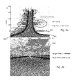
- two hyperbolic curves are fit to 3D points represented in a camera centered two-dimensional Z-u plane, as shown in Figure 3a.
- Figure 3a is a top view of the scene as 3D LiDAR points. 3D points that are far from camera center and behind these two hyperbolic curves 300, 302 are considered outliers and are thus removed. However, points with depth less than 50 meters (see the line 304) are kept because they may have significance when labelling roads or other near objects.
- Figure 3b illustrates a front camera view of the scene, where the occluded points in the bystreet located in the square 306, which correspond to line 304 in Figure 3a as having with depth more than 50 meters, will be deleted.
- extracting a plurality of 3D features for each patch involves extracting camera pose independent features and camera location dependent features.
- the camera pose independent features include one or more of the following:
- Surface normal may be extraced for each patch. Then an accurate method to compute the surface normal may be applied by fitting a plane to the 3D points in each patch. For example, the RANSAC algorithm may be used to remove outliers which may correspond to very "close" objects such as a pedestrian or a vehicle.
- Patch planarity may be defined as the average square distance of all 3D points from the best fitted plane computed by the RANSAC algorithm. This feature may be useful for distinguishing planar objects, such as buildings, from non-planar objects, such as trees.
- Density Some objects, such as road and sky, have lower density of point cloud as compared to others, such as trees and vegetation. Therefore, the number of 3D points in a patch may be used as a strong cue to distinguish different classes.
- LiDAR systems provide not only positioning information but also reflectance property, referred to as intensity, of laser scanned objects.
- the intensity feature may be used herein, in combination with other features, to classify 3D points. More specifically, the median intensity of points in each patch may be used to train the classifier.
- the camera location dependent features include one or more of the following:
- Depth to camera Depth information helps to distinguish objects, such that the 3D spatial location of each patch may be estimated.
- a trained classifier for assigning at least one vector representing a 3D feature with a semantic label, may be used.
- the training of the classifier may be offline training, which is based on boosted decision trees, where a set of 3D features are associated with manually labeled SPs in training images.
- the boosted decision trees have demonstrated superior classification accuracy and robustness in many multi-class classification tasks.
- An example of boosted decision tress is disclosed e.g. in " Logistic regression, adaboost and bregman distances," by M. Collins, R. Schapire, and Y. Singer; Machine Learning, vol. 48, no. 1-3, 2002 . Acting as weaker learners, decision trees automatically select features that are relevant to the given classification problem. Given different weights of training samples, multiple trees are trained to minimize average classification errors. Subsequently, boosting is done by logistic regression version of Adaboost to achieve higher accuracy with multiple trees combined together.
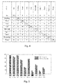
- the table in Figure 4 shows a confusion matrix resulting from the experiments, illustrating the identification accuracy in those 10 semantic object classes.
- the results show that for larger objects, such as sky, building, road, tree and sidewalk, the accuracy of correctly classifies superpixels was very high, 77 - 96 %, depending on the object.
- each semantic object class represents the accuracy, when the intensity feature is utilized in training samples, and the right-hand bar represents the accuracy without the intensity feature.
- the accuracy is improved when the intensity feature is utilized in training samples, but the most significant improvement is achieved for small objects, such as pedestrian and sign-symbol.
- the various embodiments may provide advantages over state of the art.
- the overall usage of 3D LiDAR point clouds for street view scene parsing improves parsing accuracies under challenging conditions such as varying lighting and urban structures.
- the improvement is achieved by circumventing error-prone 2D feature extraction and matching steps.
- the embodiments for registering 3D point cloud to 2D image plane enables to remove occluded points from behind the buildings in an efficient manner.
- the novel LiDAR point reflectance property, i.e. intensity feature for semantic scene parsing enables to combine both LiDAR intensity feature and geometric features such that more robust classification results may be obtained. Consequently, classifiers trained in one type of city and weather condition is now possible to be applied to a different scene structure with high accuracy.
- an apparatus may comprise circuitry and electronics for handling, receiving and transmitting data, computer program code in a memory, and a processor that, when running the computer program code, causes the terminal device to carry out the features of an embodiment.
Landscapes
- Engineering & Computer Science (AREA)
- Physics & Mathematics (AREA)
- General Physics & Mathematics (AREA)
- Theoretical Computer Science (AREA)
- Multimedia (AREA)
- Computer Vision & Pattern Recognition (AREA)
- Image Processing (AREA)
- Image Analysis (AREA)
- Image Generation (AREA)
Abstract
Description
- The present invention relates to image processing, and more particularly to a process of automatic scene parsing.
- Automatic scene parsing is a traditional computer vision problem. Automatic urban scene parsing refers to the process of segmentation and classifying of objects of interest in an image into predefined semantic labels, such as "building", "tree" or "road". This typically involves a fixed number of object categories, each of which requires a training model for classifying image segments. While many techniques for two-dimensional (2D) object recognition have been proposed, the accuracy of these systems is to some extent unsatisfactory because 2D image cues are sensitive to varying imaging conditions such as lighting, shadow etc.
- Many successful scene parsing techniques have used single 2D image appearance information, such as color, texture and shape. A drawback of single image feature extraction techniques is that they are sensitive to different image capturing conditions, such as lighting, camera viewpoint and scene structure. Recently, many efforts have been made to employ 3D scene features derived from single 2D images to achieve more accurate object recognition. Especially, when the input data is a video sequence, 3D cues can be extracted using Structure From Motion (SFM) techniques.
- However, the SFM technique adopted in scene parsing systems is known to be fragile in outdoor environment because of the difficulty in obtaining correct correspondence in cases of sparse texture or occlusion in the images.
- Now there has been invented an improved method and technical equipment implementing the method, by which the above problems are at least alleviated. Various aspects of the invention include a method, an apparatus and a computer program, which are characterized by what is stated in the independent claims. Various embodiments of the invention are disclosed in the dependent claims.
- According to a first aspect, a method according to the invention is based on the idea of obtaining an image about at least one object of interest and a three-dimensional (3D) point cloud about said object of interest; aligning the 3D point cloud with the image; segmenting the image into a plurality of superpixels preserving a graph structure and spatial neighbourhood of pixel data of the image; associating the superpixels in the image with a subset of said 3D points, said subset of 3D points representing a planar patch in said object of interest; extracting a plurality of 3D features for each patch; and assigning at least one vector representing at least one 3D feature with a semantic label on the basis of at least one extracted 3D feature of the patch.
- According to an embodiment, the 3D point cloud is derived using Light Detection And Ranging (LiDAR) method.
- According to an embodiment, the method further comprises establishing correspondences between at least one subset of 3D points and at least one superpixel of the image.
- According to an embodiment, the method further comprises segmenting the image into superpixels of substantially the same size.
- According to an embodiment, extracting a plurality of 3D features for each patch involves extracting camera pose independent features and camera location dependent features.
- According to an embodiment, the camera pose independent features include one or more of the following:
- height of the patch above ground;
- surface normal of the patch;
- patch planarity;
- density of 3D points in the patch;
- intensity of the patch defined as a function of reflectance of the light beams.
- According to an embodiment, the camera location dependent features include one or more of the following:
- horizontal distance of the patch to camera;
- depth information of the patch to camera.
- According to an embodiment, the method further comprises using a trained classifier algorithm for assigning said at least one vector representing the 3D feature with the semantic label.
- According to an embodiment, the trained classifier algorithm is based on boosted decision trees, where a set of 3D features have been associated with manually labeled superpixels in training images during offline training.
- According to a second aspect, there is provided an apparatus comprising at least one processor, memory including computer program code, the memory and the computer program code configured to, with the at least one processor, cause the apparatus to at least:
- obtain an image about at least one object of interest and a three-dimensional (3D) point cloud about said object of interest;
- align the 3D point cloud with the image;
- segment the image into a plurality of superpixels preserving a graph structure and spatial neighbourhood of pixel data of the image;
- associate the superpixels in the image with a subset of said 3D points, said subset of 3D points representing a planar patch in said object of interest;
- extract a plurality of 3D features for each patch; and
- assign at least one vector representing at least one 3D feature with a semantic label on the basis of at least one extracted 3D feature of the patch.
- According to a third aspect, there is provided a computer readable storage medium stored with code thereon for use by an apparatus, which when executed by a processor, causes the apparatus to perform:
- obtaining an image about at least one object of interest and a three-dimensional (3D) point cloud about said object of interest;
- aligning the 3D point cloud with the image;
- segmenting the image into a plurality of superpixels preserving a graph structure and spatial neighbourhood of pixel data of the image;
- associating the superpixels in the image with a subset of said 3D points, said subset of 3D points representing a planar patch in said object of interest;
- extracting a plurality of 3D features for each patch; and
- assigning at least one vector representing at least one 3D feature with a semantic label on the basis of at least one extracted 3D feature of the patch.
- These and other aspects of the invention and the embodiments related thereto will become apparent in view of the detailed disclosure of the embodiments further below.
- In the following, various embodiments of the invention will be described in more detail with reference to the appended drawings, in which
- Fig. 1
- show a computer graphics system suitable to be used in an automatic scene parsing process according to an embodiment;
- Fig. 2
- shows a flow chart of an automatic scene parsing process according to an embodiment of the invention;
- Figs. 3a, 3b
- illustrate an example of removing occluded points from the classification according to an embodiment of the invention;
- Fig. 4
- shows a table of identification accuracy in an experiment carried out according to an embodiment of the invention; and
- Fig. 5
- shows a table of the effect of an intensity feature used in an experiment carried out according to a further embodiment of the invention.
-
Figure 1 shows a computer graphics system suitable to be used in image processing, for example in automatic scene parsing process according to an embodiment. The generalized structure of the computer graphics system will be explained in accordance with the functional blocks of the system. For a skilled man, it will be obvious that several functionalities can be carried out with a single physical device, e.g. all calculation procedures can be performed in a single processor, if desired. A data processing system of an apparatus according to an example ofFig. 1 includes amain processing unit 100, amemory 102, astorage device 104, aninput device 106, anoutput device 108, and agraphics subsystem 110, which all are connected to each other via adata bus 112. - The
main processing unit 100 is a conventional processing unit arranged to process data within the data processing system. Thememory 102, thestorage device 104, theinput device 106, and theoutput device 108 are conventional components as recognized by those skilled in the art. Thememory 102 andstorage device 104 store data within thedata processing system 100. Computer program code resides in thememory 102 for implementing, for example, an automatic scene parsing process. Theinput device 106 inputs data into the system while theoutput device 108 receives data from the data processing system and forwards the data, for example to a display. Thedata bus 112 is a conventional data bus and while shown as a single line it may be a combination of a processor bus, a PCI bus, a graphical bus, and an ISA bus. Accordingly, a skilled man readily recognizes that the apparatus may be any conventional data processing device, such as a computer device, a personal computer, a server computer, a mobile phone, a smart phone or an Internet access device, for example Internet tablet computer. The input data of the automatic scene parsing process according to an embodiment and means for obtaining the input data are described further below. - It needs to be understood that different embodiments allow different parts to be carried out in different elements. For example, various processes of the scene parsing may be carried out in one or more processing devices; for example, entirely in one computer device, or in one server device or across multiple user devices The elements of the automatic scene parsing process may be implemented as a software component residing on one device or distributed across several devices, as mentioned above, for example so that the devices form a so-called cloud.
- Automatic scene parsing is a traditional computer vision problem. Automatic urban scene parsing refers to the process of segmentation and classifying of objects of interest in an image into predefined semantic labels, such as "building", "tree" or "road". This typically involves a fixed number of object categories, each of which requires a training model for classifying image segments.
- Many successful scene parsing techniques have used single 2D image appearance information, such as color, texture and shape. A drawback of single image feature extraction techniques is that they are sensitive to different image capturing conditions, such as lighting, camera viewpoint and scene structure. Recently, many efforts have been made to employ 3D scene features derived from single 2D images to achieve more accurate object recognition. Especially, when the input data is a video sequence, 3D cues can be extracted using Structure From Motion (SFM) techniques. Nevertheless, the SFM technique adopted in scene parsing systems is vulnerable in outdoor environment because of the difficulty in obtaining correct correspondence in cases of sparse texture or occlusion in the images.
- Herein below, a novel automatic scene parsing approach is presented, which takes advantage of 3D geometrical features of the object of interest, for which accurate, high-
resolution 3D information (e.g. longitude, latitude, altitude) as well as reflectance properties of urban environment in or around the object of interest may have been derived. - The method according to the embodiment is illustrated in
Figure 2 . Representing images with a limited number of pixel groups rather than individual pixels, thus decreasing significantly the number of computation nodes with the image, as well as the computational complexity, is generally called superpixel segmentation, turbopixel segmentation or over-segmentation. Superpixels may be created in various ways, for example by grouping similarly colored or otherwise homogenous pixels via merging. - In the method of
Figure 2 , an image about an object of interest and a three-dimensional (3D) point cloud about said object of interest is obtained (200) as an input for the process. The 3D point cloud is then aligned (202) with the two-dimensional image. Next, the image is segmented (204) into superpixels preserving a graph structure and spatial neighbourhood of pixel data of the image. A plurality of superpixels, preferably each superpixel in the image is associated (206) with a subset of said 3D points, said subset of 3D points representing a planar patch in said object of interest. A plurality of 3D features are extracted (208) for each patch, and at least one vector representing a 3D feature is assigned (210) with a semantic label, such as "sky", "road", "building", etc., based on at least one extracted 3D feature. - According to an embodiment, the 3D point cloud is derived using Light Detection And Ranging (LiDAR) method. In the LiDAR method, distances are measured by illuminating a target with a laser beam (e.g. ultraviolet, visible, or near-infrared light) and analyzing the reflected light. The resulting data is stored as point clouds. The LiDAR point clouds may be considered a set of vertices in a three-dimensional coordinate system, wherein a vertex may be represented by a planar patch defined by a 3D vector.
- Mobile Terrestrial LiDAR (MTL) provides accurate, high-
resolution 3D information (e.g. longitude, latitude, altitude) as well as reflectance properties of urban environment. For obtainingMTL 3D information about an environment, for example a vehicle-based mobile mapping system may be used. Such a mobile mapping system may comprise at least a panoramic camera capable of capturing 360° panoramic view around the moving vehicle and a plurality (e.g. 4-8) of hi-resolution cameras, each arranged to capture a segment of the 360° panoramic view around the moving vehicle. The mobile mapping system may comprise a LiDAR unit for scanning the surroundings with a laser beam, analysing the reflected light and storing the results as point clouds. The LiDAR unit may comprise, for example, a LiDAR sensor consisting of 64 lasers mounted on upper and lower blocks with 32 lasers in each side and the entire unit spins. The LiDAR unit may generate and store, for example, 1.5 million points per second. The mobile mapping system may further comprise a satellite positioning unit, such as a GPS receiver, for determining the accurate location the moving vehicle and Inertial Measurement Unit (IMU) and Distance Measurement Instrument (DMI). The vehicle may be driven at the posted speed limit and the sensors are calibrated and synchronized to produce a coupled collection of high quality geo-referenced (i.e. latitude, longitude and altitude) data. The perspective camera image is generated by rendering the spherical panorama, for example with a view port of 2032×2032 pixels. - According to an embodiment, for aligning a 3D point cloud and a 2D image with known viewing camera pose, correspondences between collections of 3D points and groups of 2D image pixels are established. In particular, every collection of 3D points is assumed to be sampled from a visible planar 3D object, i.e. a patch, and corresponding 2D projections are confined within a homogenous region, i.e. superpixels (SPs) of the image. While the 3D-2D projection between patches and SPs is straightforward for known geometrical configurations, it still remains a challenging task to deal with
outlier 3D points in a computationally efficient manner. - According to an embodiment, a 3D point is projected on a 2D image plane with a known viewing camera pose as follows: for a given viewing camera pose i.e. position and orientation, represented, respectively, by a 3×1 translation vector T and a 3×3 rotation matrix R, and a 3D point M=[X,Y,Z]t, expressed in a Euclidean world coordinate system, then the 2D image projection mp= [u, v]t of the point M is given by


- 3D Light Detection And Ranging (LiDAR) point clouds are often measured in a geographic coordinate system (i.e. longitude, latitude, altitude). Therefore, projecting a 3D LiDAR point on 2D image plane involves two more transformation steps, where the geographic coordinates are first transformed to Earth-Centered-Earth-Fixed coordinates (i.e. Geo-to-ECEF transformation) and then further to North-East-Down coordinates (i.e. ECEF-to-NED transformation). After these two transformations, a 3D point in the NED coordinate aligns to image plane by equation (2).
- According to an embodiment, images are segmented into superpixels of roughly the same size. Herein, a geometric-flow based technique disclosed e.g. in "TurboPixels: Fast Superpixels Using Geometric Flows," by A. Levinshtein, A. Stere, K. N. Kutulakos, D. J. Fleet, S. J. Dickinson, and K. Siddiqi; IEEE Trans. on Pattern Analysis and Machine Intelligence, vol. 31, no. 12, p. 2290-2297, 2009. Sharp image edges are also well preserved by this method. For example, if the input images have a resolution of 2032×2032 pixels, the initial number of superpixels for each image may be set as 2500. In other words, while the number of pixels within a superpixel may vary, the average number of pixels within a superpixel would be approximately 1650 pixels/SP.
- According to an embodiment, those 3D points that are projected within a specific SP may be identified by using the projection step in equation (2) and necessary transformation steps. Assuming there is only one dominant 3D patch that associates with the given SP, the
outlier 3D points that are far from the patch should be removed. - According to an embodiment, the outlier removal method presented herein takes advantage of prior knowledge about urban scene environment and assumes that there are building facades along both sides of the street. While this assumption appears to be oversimplified, the experimental results have shown that the method performs quite well with various urban scenes. The simplified assumption enables to use a computationally lightweight method to remove outlier points for all SPs in one pass.
- According to an embodiment, in the method two hyperbolic curves are fit to 3D points represented in a camera centered two-dimensional Z-u plane, as shown in
Figure 3a. Figure 3a is a top view of the scene as 3D LiDAR points. 3D points that are far from camera center and behind these twohyperbolic curves -
Figure 3b illustrates a front camera view of the scene, where the occluded points in the bystreet located in the square 306, which correspond toline 304 inFigure 3a as having with depth more than 50 meters, will be deleted. - According to an embodiment, the derivation of hyperbolic curves in this Z-u plane is due to the normalization of homogeneous coordinates:

hyperbolic curves Figure 3a . - According to an embodiment, extracting a plurality of 3D features for each patch involves extracting camera pose independent features and camera location dependent features.
- According to an embodiment, the camera pose independent features include one or more of the following:
- Height above ground: Given a collection of 3D points with known geographic coordinates, the median height of all points may be considered to be the height feature of the patch. The height information is independent of the camera pose and may be calculated by measuring the distance between points and the road ground. In contrast to 3D point clouds reconstructed with SFM technique, the advantage of LiDAR point cloud is that the exact measure of points' height is known and it is not necessary to use e.g. the computationally heavy RANSAC (RANdom SAmple Consensus) method to estimate the ground plane.
- Surface normal: Surface normal may be extraced for each patch. Then an accurate method to compute the surface normal may be applied by fitting a plane to the 3D points in each patch. For example, the RANSAC algorithm may be used to remove outliers which may correspond to very "close" objects such as a pedestrian or a vehicle.
- Planarity: Patch planarity may be defined as the average square distance of all 3D points from the best fitted plane computed by the RANSAC algorithm. This feature may be useful for distinguishing planar objects, such as buildings, from non-planar objects, such as trees.
- Density: Some objects, such as road and sky, have lower density of point cloud as compared to others, such as trees and vegetation. Therefore, the number of 3D points in a patch may be used as a strong cue to distinguish different classes.
- Intensity: LiDAR systems provide not only positioning information but also reflectance property, referred to as intensity, of laser scanned objects. The intensity feature may be used herein, in combination with other features, to classify 3D points. More specifically, the median intensity of points in each patch may be used to train the classifier.
- According to an embodiment, the camera location dependent features include one or more of the following:
- Horizontal distance to camera: The horizontal distance of the each patch to the camera is measured as a geographical feature.
- Depth to camera: Depth information helps to distinguish objects, such that the 3D spatial location of each patch may be estimated.
- According to an embodiment, for assigning at least one vector representing a 3D feature with a semantic label, a trained classifier may be used. According to an embodiment, the training of the classifier may be offline training, which is based on boosted decision trees, where a set of 3D features are associated with manually labeled SPs in training images.
- The boosted decision trees have demonstrated superior classification accuracy and robustness in many multi-class classification tasks. An example of boosted decision tress is disclosed e.g. in "Logistic regression, adaboost and bregman distances," by M. Collins, R. Schapire, and Y. Singer; Machine Learning, vol. 48, no. 1-3, 2002. Acting as weaker learners, decision trees automatically select features that are relevant to the given classification problem. Given different weights of training samples, multiple trees are trained to minimize average classification errors. Subsequently, boosting is done by logistic regression version of Adaboost to achieve higher accuracy with multiple trees combined together.
- A skilled man appreciates that any of the embodiments described above may be implemented as a combination with one or more of the other embodiments, unless there is explicitly or implicitly stated that certain embodiments are only alternatives to each other.
- The automatic scene parsing method and its embodiments as described above were tested in comprehensive experiments in three cities in different weather conditions and city landscapes. In the experiments, 20 decision trees were used, each of which had 10 leaf nodes, thus enabling to label 10 semantic object classes: building, tree, sky, car, sign-symbol, pedestrian, road, fence, sidewalk and water.
- The table in
Figure 4 shows a confusion matrix resulting from the experiments, illustrating the identification accuracy in those 10 semantic object classes. The results show that for larger objects, such as sky, building, road, tree and sidewalk, the accuracy of correctly classifies superpixels was very high, 77 - 96 %, depending on the object. - Applying SP based segmentation to relatively small objects, such as pedestrian and sign-symbol, often leads to insufficient number of training samples, and hence, low classification accuracies of about 10%. However, when using the LiDAR point reflectance property, i.e. intensity feature, for object classification, the accuracy may be significantly improved, even doubled to about 20%.
- This is illustrated in the table of
Figure 5 , where the left-hand bar for each semantic object class represents the accuracy, when the intensity feature is utilized in training samples, and the right-hand bar represents the accuracy without the intensity feature. In each semantic object class, the accuracy is improved when the intensity feature is utilized in training samples, but the most significant improvement is achieved for small objects, such as pedestrian and sign-symbol. - As confirmed by the experiments, the various embodiments may provide advantages over state of the art. The overall usage of 3D LiDAR point clouds for street view scene parsing improves parsing accuracies under challenging conditions such as varying lighting and urban structures. The improvement is achieved by circumventing error-prone 2D feature extraction and matching steps. Moreover, the embodiments for registering 3D point cloud to 2D image plane enables to remove occluded points from behind the buildings in an efficient manner. In addition, the novel LiDAR point reflectance property, i.e. intensity feature for semantic scene parsing, enables to combine both LiDAR intensity feature and geometric features such that more robust classification results may be obtained. Consequently, classifiers trained in one type of city and weather condition is now possible to be applied to a different scene structure with high accuracy.
- The various embodiments of the invention can be implemented with the help of computer program code that resides in a memory and causes the relevant apparatuses to carry out the invention. For example, an apparatus may comprise circuitry and electronics for handling, receiving and transmitting data, computer program code in a memory, and a processor that, when running the computer program code, causes the terminal device to carry out the features of an embodiment.
- It is obvious that the present invention is not limited solely to the above-presented embodiments, but it can be modified within the scope of the appended claims.
Claims (12)
- A method comprising:obtaining an image about at least one object of interest and a three-dimensional (3D) point cloud about said object of interest;aligning the 3D point cloud with the image;segmenting the image into a plurality of superpixels preserving a graph structure and spatial neighbourhood of pixel data of the image;associating the superpixels in the image with a subset of said 3D points, said subset of 3D points representing a planar patch in said object of interest;extracting a plurality of 3D features for each patch; andassigning at least one vector representing at least one 3D feature with a semantic label on the basis of at least one extracted 3D feature of the patch.
- The method according to claim 1, wherein the 3D point cloud is derived using Light Detection And Ranging (LiDAR) method.
- The method according to claim 1 or 2, the method further comprising:establishing correspondences between at least one subset of 3D points and at least one superpixel of the image.
- The method according to any preceding claim, the method further comprising:segmenting the image into superpixels of substantially the same size.
- The method according to any preceding claim, wherein extracting a plurality of 3D features for each patch involves extracting camera pose independent features and camera location dependent features.
- The method according to claim 5, wherein the camera pose independent features include one or more of the following:- height of the patch above ground;- surface normal of the patch;- patch planarity;- density of 3D points in the patch;- intensity of the patch defined as a function of reflectance of the light beams.
- The method according to claim 5, wherein the camera location dependent features include one or more of the following:- horizontal distance of the patch to camera;- depth information of the patch to camera.
- The method according to any preceding claim, the method further comprising:using a trained classifier algorithm for assigning said at least one vector representing the 3D feature with the semantic label.
- The method according to claim 8, wherein the trained classifier algorithm is based on boosted decision trees, where a set of 3D features have been associated with manually labeled superpixels in training images during offline training.
- An apparatus comprising at least one processor, memory including computer program code, the memory and the computer program code configured to, with the at least one processor, cause the apparatus to at least:obtain an image about at least one object of interest and a three-dimensional (3D) point cloud about said object of interest;align the 3D point cloud with the image;segment the image into a plurality of superpixels preserving a graph structure and spatial neighbourhood of pixel data of the image;associate the superpixels in the image with a subset of said 3D points, said subset of 3D points representing a planar patch in said object of interest;extract a plurality of 3D features for each patch; andassign at least one vector representing at least one 3D feature with a semantic label on the basis of at least one extracted 3D feature of the patch.
- An apparatus according to claim 10, wherein the apparatus is further configured to perform the method as claimed in any of the claims 2 to 9.
- A computer program product comprising program instructions which when executed by an apparatus cause the apparatus to perform the method as claimed in any of the claims 1 to 9.
Applications Claiming Priority (1)
| Application Number | Priority Date | Filing Date | Title |
|---|---|---|---|
| GB1320361.7A GB2520338A (en) | 2013-11-19 | 2013-11-19 | Automatic scene parsing |
Publications (2)
| Publication Number | Publication Date |
|---|---|
| EP2874097A2 true EP2874097A2 (en) | 2015-05-20 |
| EP2874097A3 EP2874097A3 (en) | 2015-07-29 |
Family
ID=49883807
Family Applications (1)
| Application Number | Title | Priority Date | Filing Date |
|---|---|---|---|
| EP14191033.1A Withdrawn EP2874097A3 (en) | 2013-11-19 | 2014-10-30 | Automatic scene parsing |
Country Status (3)
| Country | Link |
|---|---|
| US (1) | US20150138310A1 (en) |
| EP (1) | EP2874097A3 (en) |
| GB (1) | GB2520338A (en) |
Cited By (12)
| Publication number | Priority date | Publication date | Assignee | Title |
|---|---|---|---|---|
| CN103366250A (en) * | 2013-07-12 | 2013-10-23 | 中国科学院深圳先进技术研究院 | City appearance environment detection method and system based on three-dimensional live-action data |
| EP3156942A1 (en) * | 2015-10-16 | 2017-04-19 | Thomson Licensing | Scene labeling of rgb-d data with interactive option |
| CN106844610A (en) * | 2017-01-18 | 2017-06-13 | 上海交通大学 | A kind of distributed structured three-dimensional point cloud image processing method and system |
| CN107392176A (en) * | 2017-08-10 | 2017-11-24 | 华南理工大学 | A kind of high efficiency vehicle detection method based on kmeans |
| GB2553363A (en) * | 2016-09-05 | 2018-03-07 | Return To Scene Ltd | Method and system for recording spatial information |
| CN109978955A (en) * | 2019-03-11 | 2019-07-05 | 武汉环宇智行科技有限公司 | A kind of efficient mask method for combining laser point cloud and image |
| WO2019138597A1 (en) * | 2018-01-11 | 2019-07-18 | Mitsubishi Electric Corporation | System and method for assigning semantic label to three-dimensional point of point cloud |
| US10424065B2 (en) | 2016-06-10 | 2019-09-24 | The Board Of Trustees Of The Leland Stanford Junior University | Systems and methods for performing three-dimensional semantic parsing of indoor spaces |
| CN110807774A (en) * | 2019-09-30 | 2020-02-18 | 广东工业大学 | Point cloud classification and semantic segmentation method |
| US10712747B2 (en) * | 2016-01-18 | 2020-07-14 | Tencent Technology (Shenzhen) Company Limited | Data processing method, apparatus and terminal |
| WO2021004813A1 (en) * | 2019-07-08 | 2021-01-14 | Continental Automotive Gmbh | Method and mobile entity for detecting feature points in an image |
| CN116486283A (en) * | 2023-01-09 | 2023-07-25 | 深圳优立全息科技有限公司 | Real-time point cloud target detection method and device based on voxel division |
Families Citing this family (43)
| Publication number | Priority date | Publication date | Assignee | Title |
|---|---|---|---|---|
| US9704055B2 (en) | 2013-11-07 | 2017-07-11 | Autodesk, Inc. | Occlusion render mechanism for point clouds |
| JP6426968B2 (en) * | 2014-10-08 | 2018-11-21 | キヤノン株式会社 | INFORMATION PROCESSING APPARATUS AND METHOD THEREOF |
| US20160267669A1 (en) * | 2015-03-12 | 2016-09-15 | James W. Justice | 3D Active Warning and Recognition Environment (3D AWARE): A low Size, Weight, and Power (SWaP) LIDAR with Integrated Image Exploitation Processing for Diverse Applications |
| DE102015214743A1 (en) * | 2015-08-03 | 2017-02-09 | Audi Ag | Method and device in a motor vehicle for improved data fusion in an environment detection |
| CA2943068A1 (en) * | 2015-09-25 | 2017-03-25 | Logical Turn Services Inc. | Dimensional acquisition of packages |
| US10769806B2 (en) * | 2015-09-25 | 2020-09-08 | Logical Turn Services, Inc. | Dimensional acquisition of packages |
| US10451407B2 (en) * | 2015-11-23 | 2019-10-22 | The Boeing Company | System and method of analyzing a curved surface |
| US10424072B2 (en) * | 2016-03-01 | 2019-09-24 | Samsung Electronics Co., Ltd. | Leveraging multi cues for fine-grained object classification |
| KR102040156B1 (en) * | 2016-03-02 | 2019-11-05 | 한국전자통신연구원 | Apparatus and method for editing 3D data of a building |
| US10579860B2 (en) | 2016-06-06 | 2020-03-03 | Samsung Electronics Co., Ltd. | Learning model for salient facial region detection |
| US10210603B2 (en) * | 2016-10-17 | 2019-02-19 | Conduent Business Services Llc | Store shelf imaging system and method |
| KR102406502B1 (en) * | 2016-12-14 | 2022-06-10 | 현대자동차주식회사 | Apparatus and method for controlling narrow road driving of vehicle |
| US10354411B2 (en) * | 2016-12-20 | 2019-07-16 | Symbol Technologies, Llc | Methods, systems and apparatus for segmenting objects |
| CN111542860B (en) * | 2016-12-30 | 2024-08-27 | 辉达公司 | Sign and lane creation for high definition maps of autonomous vehicles |
| WO2018170472A1 (en) * | 2017-03-17 | 2018-09-20 | Honda Motor Co., Ltd. | Joint 3d object detection and orientation estimation via multimodal fusion |
| US10809380B2 (en) | 2017-05-15 | 2020-10-20 | Ouster, Inc. | Augmenting panoramic LIDAR results with color |
| JP7113283B2 (en) * | 2017-05-26 | 2022-08-05 | パナソニックIpマネジメント株式会社 | Imaging device, imaging system, vehicle driving control system, and image processing device |
| CN107492148B (en) * | 2017-08-17 | 2018-03-27 | 广东工业大学 | It is extensive without demarcation surface points cloud reconstruction face of cylinder method based on SVM and K Means |
| US10872228B1 (en) | 2017-09-27 | 2020-12-22 | Apple Inc. | Three-dimensional object detection |
| CN111819567A (en) * | 2018-03-01 | 2020-10-23 | 英特尔公司 | Method and apparatus for matching images using semantic features |
| US11768292B2 (en) * | 2018-03-14 | 2023-09-26 | Uatc, Llc | Three-dimensional object detection |
| US10540785B2 (en) * | 2018-05-30 | 2020-01-21 | Honeywell International Inc. | Compressing data points into polygons |
| US10445599B1 (en) * | 2018-06-13 | 2019-10-15 | Luminar Technologies, Inc. | Sensor system augmented with thermal sensor object confirmation |
| CN110638477B (en) * | 2018-06-26 | 2023-08-11 | 佳能医疗系统株式会社 | Medical image diagnosis device and alignment method |
| CN108961397B (en) * | 2018-07-05 | 2022-06-21 | 长春工程学院 | Tree-oriented three-dimensional point cloud data simplification method |
| CN110378359B (en) * | 2018-07-06 | 2021-11-05 | 北京京东尚科信息技术有限公司 | Image identification method and device |
| US11138762B2 (en) | 2018-07-11 | 2021-10-05 | Samsung Electronics Co., Ltd. | Visual quality of video based point cloud compression using one or more additional patches |
| US11067693B2 (en) | 2018-07-12 | 2021-07-20 | Toyota Research Institute, Inc. | System and method for calibrating a LIDAR and a camera together using semantic segmentation |
| US11100669B1 (en) | 2018-09-14 | 2021-08-24 | Apple Inc. | Multimodal three-dimensional object detection |
| WO2020072579A1 (en) | 2018-10-02 | 2020-04-09 | Futurewei Technologies, Inc. | Motion estimation using 3d auxiliary data |
| US11055546B2 (en) | 2018-12-18 | 2021-07-06 | Here Global B.V. | Automatic positioning of 2D image sign sightings in 3D space |
| US11113959B2 (en) * | 2018-12-28 | 2021-09-07 | Intel Corporation | Crowdsourced detection, identification and sharing of hazardous road objects in HD maps |
| CN109855624A (en) * | 2019-01-17 | 2019-06-07 | 宁波舜宇智能科技有限公司 | Navigation device and air navigation aid for AGV vehicle |
| CN110084840B (en) * | 2019-04-24 | 2022-05-13 | 阿波罗智能技术(北京)有限公司 | Point cloud registration method, device, server and computer readable medium |
| CN110232329B (en) * | 2019-05-23 | 2023-04-18 | 星际空间(天津)科技发展有限公司 | Point cloud classification method and device based on deep learning, storage medium and equipment |
| US10885386B1 (en) | 2019-09-16 | 2021-01-05 | The Boeing Company | Systems and methods for automatically generating training image sets for an object |
| US11113570B2 (en) | 2019-09-16 | 2021-09-07 | The Boeing Company | Systems and methods for automatically generating training image sets for an environment |
| US11195065B2 (en) | 2019-11-22 | 2021-12-07 | Samsung Electronics Co., Ltd. | System and method for joint image and lidar annotation and calibration |
| CN111325779B (en) * | 2020-02-07 | 2020-12-11 | 贝壳找房(北京)科技有限公司 | Point cloud registration method and device, electronic equipment and storage medium |
| US11375352B2 (en) | 2020-03-25 | 2022-06-28 | Intel Corporation | Devices and methods for updating maps in autonomous driving systems in bandwidth constrained networks |
| US11614514B2 (en) * | 2020-03-27 | 2023-03-28 | Intel Corporation | Apparatus, system and method of generating radar perception data |
| US11715299B1 (en) * | 2020-05-29 | 2023-08-01 | Apple Inc. | Semantic labeling of negative spaces |
| US11756317B2 (en) | 2020-09-24 | 2023-09-12 | Argo AI, LLC | Methods and systems for labeling lidar point cloud data |
Family Cites Families (6)
| Publication number | Priority date | Publication date | Assignee | Title |
|---|---|---|---|---|
| US7167871B2 (en) * | 2002-05-17 | 2007-01-23 | Xerox Corporation | Systems and methods for authoritativeness grading, estimation and sorting of documents in large heterogeneous document collections |
| US8751156B2 (en) * | 2004-06-30 | 2014-06-10 | HERE North America LLC | Method of operating a navigation system using images |
| US8179393B2 (en) * | 2009-02-13 | 2012-05-15 | Harris Corporation | Fusion of a 2D electro-optical image and 3D point cloud data for scene interpretation and registration performance assessment |
| US9117281B2 (en) * | 2011-11-02 | 2015-08-25 | Microsoft Corporation | Surface segmentation from RGB and depth images |
| EP2637139A1 (en) * | 2012-03-05 | 2013-09-11 | Thomson Licensing | Method and apparatus for bi-layer segmentation |
| CN103093191B (en) * | 2012-12-28 | 2016-06-15 | 中电科信息产业有限公司 | A kind of three dimensional point cloud is in conjunction with the object identification method of digital image data |
-
2013
- 2013-11-19 GB GB1320361.7A patent/GB2520338A/en not_active Withdrawn
-
2014
- 2014-10-30 EP EP14191033.1A patent/EP2874097A3/en not_active Withdrawn
- 2014-11-05 US US14/534,124 patent/US20150138310A1/en not_active Abandoned
Non-Patent Citations (1)
| Title |
|---|
| JAN SIEGEMUND: "Street Surfaces and Boundaries from Depth Image Sequences Using Probabilistic Models", 26 April 2013 (2013-04-26), BONN, XP055307715, Retrieved from the Internet <URL:http://hss.ulb.uni-bonn.de/2013/3436/3436.pdf> [retrieved on 20161005] * |
Cited By (16)
| Publication number | Priority date | Publication date | Assignee | Title |
|---|---|---|---|---|
| CN103366250A (en) * | 2013-07-12 | 2013-10-23 | 中国科学院深圳先进技术研究院 | City appearance environment detection method and system based on three-dimensional live-action data |
| EP3156942A1 (en) * | 2015-10-16 | 2017-04-19 | Thomson Licensing | Scene labeling of rgb-d data with interactive option |
| US10026017B2 (en) | 2015-10-16 | 2018-07-17 | Thomson Licensing | Scene labeling of RGB-D data with interactive option |
| US11320833B2 (en) | 2016-01-18 | 2022-05-03 | Tencent Technology (Shenzhen) Company Limited | Data processing method, apparatus and terminal |
| US10712747B2 (en) * | 2016-01-18 | 2020-07-14 | Tencent Technology (Shenzhen) Company Limited | Data processing method, apparatus and terminal |
| US10424065B2 (en) | 2016-06-10 | 2019-09-24 | The Board Of Trustees Of The Leland Stanford Junior University | Systems and methods for performing three-dimensional semantic parsing of indoor spaces |
| GB2553363B (en) * | 2016-09-05 | 2019-09-04 | Return To Scene Ltd | Method and system for recording spatial information |
| GB2553363A (en) * | 2016-09-05 | 2018-03-07 | Return To Scene Ltd | Method and system for recording spatial information |
| CN106844610A (en) * | 2017-01-18 | 2017-06-13 | 上海交通大学 | A kind of distributed structured three-dimensional point cloud image processing method and system |
| CN107392176A (en) * | 2017-08-10 | 2017-11-24 | 华南理工大学 | A kind of high efficiency vehicle detection method based on kmeans |
| WO2019138597A1 (en) * | 2018-01-11 | 2019-07-18 | Mitsubishi Electric Corporation | System and method for assigning semantic label to three-dimensional point of point cloud |
| CN109978955A (en) * | 2019-03-11 | 2019-07-05 | 武汉环宇智行科技有限公司 | A kind of efficient mask method for combining laser point cloud and image |
| CN109978955B (en) * | 2019-03-11 | 2021-03-19 | 武汉环宇智行科技有限公司 | Efficient marking method combining laser point cloud and image |
| WO2021004813A1 (en) * | 2019-07-08 | 2021-01-14 | Continental Automotive Gmbh | Method and mobile entity for detecting feature points in an image |
| CN110807774A (en) * | 2019-09-30 | 2020-02-18 | 广东工业大学 | Point cloud classification and semantic segmentation method |
| CN116486283A (en) * | 2023-01-09 | 2023-07-25 | 深圳优立全息科技有限公司 | Real-time point cloud target detection method and device based on voxel division |
Also Published As
| Publication number | Publication date |
|---|---|
| US20150138310A1 (en) | 2015-05-21 |
| GB201320361D0 (en) | 2014-01-01 |
| GB2520338A (en) | 2015-05-20 |
| EP2874097A3 (en) | 2015-07-29 |
Similar Documents
| Publication | Publication Date | Title |
|---|---|---|
| EP2874097A2 (en) | Automatic scene parsing | |
| US9846946B2 (en) | Objection recognition in a 3D scene | |
| JP7485749B2 (en) | Video-based localization and mapping method and system - Patents.com | |
| JP7190842B2 (en) | Information processing device, control method and program for information processing device | |
| JP7252943B2 (en) | Object detection and avoidance for aircraft | |
| US10049492B2 (en) | Method and apparatus for rendering facades of objects of interest from three-dimensional point clouds | |
| TWI798305B (en) | Systems and methods for updating highly automated driving maps | |
| US10546387B2 (en) | Pose determination with semantic segmentation | |
| Shin et al. | Vision-based navigation of an unmanned surface vehicle with object detection and tracking abilities | |
| US8872851B2 (en) | Augmenting image data based on related 3D point cloud data | |
| US9530235B2 (en) | Aligning panoramic imagery and aerial imagery | |
| US11430199B2 (en) | Feature recognition assisted super-resolution method | |
| WO2012084703A1 (en) | Detection and tracking of moving objects | |
| CN110148223B (en) | Method and system for concentrating and expressing surveillance video target in three-dimensional geographic scene model | |
| CN114692720B (en) | Image classification method, device, equipment and storage medium based on aerial view | |
| CN111928857B (en) | Method and related device for realizing SLAM positioning in dynamic environment | |
| Xiao et al. | Geo-spatial aerial video processing for scene understanding and object tracking | |
| CN112257668A (en) | Main and auxiliary road judging method and device, electronic equipment and storage medium | |
| CN114766039A (en) | Object detection method, object detection device, terminal device, and medium | |
| CN110827340B (en) | Map updating method, device and storage medium | |
| CN113496163A (en) | Obstacle identification method and device | |
| Zhou et al. | Fast road detection and tracking in aerial videos | |
| Babahajiani et al. | Semantic parsing of street scene images using 3d lidar point cloud | |
| Jende et al. | Low-level tie feature extraction of mobile mapping data (MLS/images) and aerial imagery | |
| Ying et al. | Fully Convolutional Networks tor Street Furniture Identification in Panorama Images. |
Legal Events
| Date | Code | Title | Description |
|---|---|---|---|
| PUAI | Public reference made under article 153(3) epc to a published international application that has entered the european phase |
Free format text: ORIGINAL CODE: 0009012 |
|
| 17P | Request for examination filed |
Effective date: 20141030 |
|
| AK | Designated contracting states |
Kind code of ref document: A2 Designated state(s): AL AT BE BG CH CY CZ DE DK EE ES FI FR GB GR HR HU IE IS IT LI LT LU LV MC MK MT NL NO PL PT RO RS SE SI SK SM TR |
|
| AX | Request for extension of the european patent |
Extension state: BA ME |
|
| PUAL | Search report despatched |
Free format text: ORIGINAL CODE: 0009013 |
|
| AK | Designated contracting states |
Kind code of ref document: A3 Designated state(s): AL AT BE BG CH CY CZ DE DK EE ES FI FR GB GR HR HU IE IS IT LI LT LU LV MC MK MT NL NO PL PT RO RS SE SI SK SM TR |
|
| AX | Request for extension of the european patent |
Extension state: BA ME |
|
| RIC1 | Information provided on ipc code assigned before grant |
Ipc: G06T 7/00 20060101ALI20150619BHEP Ipc: G06K 9/00 20060101AFI20150619BHEP |
|
| RAP1 | Party data changed (applicant data changed or rights of an application transferred) |
Owner name: NOKIA TECHNOLOGIES OY |
|
| R17P | Request for examination filed (corrected) |
Effective date: 20160129 |
|
| RBV | Designated contracting states (corrected) |
Designated state(s): AL AT BE BG CH CY CZ DE DK EE ES FI FR GB GR HR HU IE IS IT LI LT LU LV MC MK MT NL NO PL PT RO RS SE SI SK SM TR |
|
| 17Q | First examination report despatched |
Effective date: 20161011 |
|
| STAA | Information on the status of an ep patent application or granted ep patent |
Free format text: STATUS: THE APPLICATION IS DEEMED TO BE WITHDRAWN |
|
| 18D | Application deemed to be withdrawn |
Effective date: 20170222 |