EP4109089A2 - System and method for dual pulse-echo sub-surface detection - Google Patents
System and method for dual pulse-echo sub-surface detection Download PDFInfo
- Publication number
- EP4109089A2 EP4109089A2 EP22180255.6A EP22180255A EP4109089A2 EP 4109089 A2 EP4109089 A2 EP 4109089A2 EP 22180255 A EP22180255 A EP 22180255A EP 4109089 A2 EP4109089 A2 EP 4109089A2
- Authority
- EP
- European Patent Office
- Prior art keywords
- processor
- scan data
- transducer
- scan
- indication
- Prior art date
- Legal status (The legal status is an assumption and is not a legal conclusion. Google has not performed a legal analysis and makes no representation as to the accuracy of the status listed.)
- Granted
Links
Images

Classifications
-
- G—PHYSICS
- G01—MEASURING; TESTING
- G01N—INVESTIGATING OR ANALYSING MATERIALS BY DETERMINING THEIR CHEMICAL OR PHYSICAL PROPERTIES
- G01N29/00—Investigating or analysing materials by the use of ultrasonic, sonic or infrasonic waves; Visualisation of the interior of objects by transmitting ultrasonic or sonic waves through the object
- G01N29/44—Processing the detected response signal, e.g. electronic circuits specially adapted therefor
- G01N29/4472—Mathematical theories or simulation
-
- G—PHYSICS
- G01—MEASURING; TESTING
- G01N—INVESTIGATING OR ANALYSING MATERIALS BY DETERMINING THEIR CHEMICAL OR PHYSICAL PROPERTIES
- G01N29/00—Investigating or analysing materials by the use of ultrasonic, sonic or infrasonic waves; Visualisation of the interior of objects by transmitting ultrasonic or sonic waves through the object
- G01N29/04—Analysing solids
- G01N29/06—Visualisation of the interior, e.g. acoustic microscopy
- G01N29/0609—Display arrangements, e.g. colour displays
- G01N29/0645—Display representation or displayed parameters, e.g. A-, B- or C-Scan
-
- G—PHYSICS
- G01—MEASURING; TESTING
- G01N—INVESTIGATING OR ANALYSING MATERIALS BY DETERMINING THEIR CHEMICAL OR PHYSICAL PROPERTIES
- G01N29/00—Investigating or analysing materials by the use of ultrasonic, sonic or infrasonic waves; Visualisation of the interior of objects by transmitting ultrasonic or sonic waves through the object
- G01N29/04—Analysing solids
- G01N29/043—Analysing solids in the interior, e.g. by shear waves
-
- G—PHYSICS
- G01—MEASURING; TESTING
- G01N—INVESTIGATING OR ANALYSING MATERIALS BY DETERMINING THEIR CHEMICAL OR PHYSICAL PROPERTIES
- G01N29/00—Investigating or analysing materials by the use of ultrasonic, sonic or infrasonic waves; Visualisation of the interior of objects by transmitting ultrasonic or sonic waves through the object
- G01N29/04—Analysing solids
- G01N29/07—Analysing solids by measuring propagation velocity or propagation time of acoustic waves
-
- G—PHYSICS
- G01—MEASURING; TESTING
- G01N—INVESTIGATING OR ANALYSING MATERIALS BY DETERMINING THEIR CHEMICAL OR PHYSICAL PROPERTIES
- G01N29/00—Investigating or analysing materials by the use of ultrasonic, sonic or infrasonic waves; Visualisation of the interior of objects by transmitting ultrasonic or sonic waves through the object
- G01N29/04—Analysing solids
- G01N29/11—Analysing solids by measuring attenuation of acoustic waves
-
- G—PHYSICS
- G01—MEASURING; TESTING
- G01N—INVESTIGATING OR ANALYSING MATERIALS BY DETERMINING THEIR CHEMICAL OR PHYSICAL PROPERTIES
- G01N29/00—Investigating or analysing materials by the use of ultrasonic, sonic or infrasonic waves; Visualisation of the interior of objects by transmitting ultrasonic or sonic waves through the object
- G01N29/22—Details, e.g. general constructional or apparatus details
- G01N29/26—Arrangements for orientation or scanning by relative movement of the head and the sensor
- G01N29/265—Arrangements for orientation or scanning by relative movement of the head and the sensor by moving the sensor relative to a stationary material
-
- G—PHYSICS
- G01—MEASURING; TESTING
- G01N—INVESTIGATING OR ANALYSING MATERIALS BY DETERMINING THEIR CHEMICAL OR PHYSICAL PROPERTIES
- G01N29/00—Investigating or analysing materials by the use of ultrasonic, sonic or infrasonic waves; Visualisation of the interior of objects by transmitting ultrasonic or sonic waves through the object
- G01N29/22—Details, e.g. general constructional or apparatus details
- G01N29/28—Details, e.g. general constructional or apparatus details providing acoustic coupling, e.g. water
-
- G—PHYSICS
- G01—MEASURING; TESTING
- G01N—INVESTIGATING OR ANALYSING MATERIALS BY DETERMINING THEIR CHEMICAL OR PHYSICAL PROPERTIES
- G01N29/00—Investigating or analysing materials by the use of ultrasonic, sonic or infrasonic waves; Visualisation of the interior of objects by transmitting ultrasonic or sonic waves through the object
- G01N29/44—Processing the detected response signal, e.g. electronic circuits specially adapted therefor
- G01N29/4409—Processing the detected response signal, e.g. electronic circuits specially adapted therefor by comparison
- G01N29/4427—Processing the detected response signal, e.g. electronic circuits specially adapted therefor by comparison with stored values, e.g. threshold values
-
- G—PHYSICS
- G01—MEASURING; TESTING
- G01N—INVESTIGATING OR ANALYSING MATERIALS BY DETERMINING THEIR CHEMICAL OR PHYSICAL PROPERTIES
- G01N29/00—Investigating or analysing materials by the use of ultrasonic, sonic or infrasonic waves; Visualisation of the interior of objects by transmitting ultrasonic or sonic waves through the object
- G01N29/44—Processing the detected response signal, e.g. electronic circuits specially adapted therefor
- G01N29/4445—Classification of defects
-
- G—PHYSICS
- G01—MEASURING; TESTING
- G01N—INVESTIGATING OR ANALYSING MATERIALS BY DETERMINING THEIR CHEMICAL OR PHYSICAL PROPERTIES
- G01N29/00—Investigating or analysing materials by the use of ultrasonic, sonic or infrasonic waves; Visualisation of the interior of objects by transmitting ultrasonic or sonic waves through the object
- G01N29/44—Processing the detected response signal, e.g. electronic circuits specially adapted therefor
- G01N29/4481—Neural networks
-
- G—PHYSICS
- G06—COMPUTING OR CALCULATING; COUNTING
- G06N—COMPUTING ARRANGEMENTS BASED ON SPECIFIC COMPUTATIONAL MODELS
- G06N20/00—Machine learning
Definitions
- the present disclosure is directed to the improved process of automatic defect recognition for the automatic inspection of engine parts using immersion pulse-echo inspection technology.
- Aerospace engine components may incur defects or imperfections during the manufacturing process.
- NDT Non- destructive testing
- Inspection methods include, but are not limited to, visual inspection, X- Ray, thermography, and ultrasonic testing. It is particularly difficult to inspect components that have an internal structure using only external observations. Forms of flaws such as porosity and inclusions in metallic parts are particularly difficult to detect. These types of defects can grow and damage the part in service.
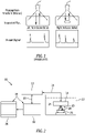
- Such internal defects are often detected by some form of excitation of the structure (ultrasonic, thermoacoustic, and the like), sensing of the excitation, and manual interpretation of the sensor signals, see for example Fig. 1 . This manual inspection process is tedious, time consuming, and error prone.
- a system for detecting a sub-surface defect comprising a transducer fluidly coupled to a part located in a tank containing a liquid configured to transmit ultrasonic energy, the transducer configured to scan the part to create scan data of the scanned part; a pulser/receiver coupled to the transducer configured to receive and transmit the scan data; a processor in electronic communication with the pulser/receiver, the processor configured to communicate with the pulser/receiver and collect the scan data; and the processor configured to detect the subsurface defect; a tangible, non-transitory memory configured to communicate with the processor, the tangible, non-transitory memory having instructions stored therein that, in response to execution by the processor, cause the processor to perform operations comprising: receiving, by the processor, the scan data for the part from the transducer; running, by the processor, a flaw detection algorithm; determining, by the processor, a part disposition; the part disposition is based on a confidence system that the processor uses to self
- the scan comprises transmitting ultrasonic energy to the part and receiving the ultrasonic energy from the part.
- the flaw detection algorithm is based on at least one inspection technique sheet.
- determining the part disposition is responsive to at least one of acceptance criteria defined in the technique sheet and the scan data.
- system further comprises providing, by the processor, further instructions to the transducer to maximize a signal-to-noise ratio to localize identified indications, wherein the indications represent at least one of a sensed flaw, defect, and discontinuity in the part.
- a system comprising a computer readable storage device readable by the system, tangibly embodying a program having a set of instructions executable by the system to perform the following steps for detecting a sub-surface defect, the set of instructions comprising: an instruction to receive scan data for a part from a transducer; an instruction to run a flaw detection algorithm; an instruction to determine a part disposition based on a confidence system that the processor uses to self-assess said part disposition; and an instruction to create a report.
- the scan data is selected from at least one of C-scans and A-scans.
- the flaw detection algorithm is based on at least one inspection technique sheet.
- the instruction to determine the part disposition is responsive to at least one of acceptance criteria defined in the technique sheet and the scan data.
- the system further comprises an instruction to the transducer to maximize a signal-to-noise ratio to localize identified indications, wherein the indications represent at least one of a sensed flaw, defect, and discontinuity in the part.
- a process for detecting a sub-surface defect by use of a system including a transducer fluidly coupled to a part located in a tank containing a liquid configured to transmit ultrasonic energy, the transducer configured to scan the part to create scan data of the scanned part; a pulser/receiver coupled to the transducer configured to receive and transmit the scan data; a processor coupled to the pulser/receiver, the processor configured to communicate with the pulser/receiver and collect the scan data; and the processor configured to detect the subsurface defect, a tangible, non-transitory memory configured to communicate with the processor, the tangible, non-transitory memory having instructions stored therein that, in response to execution by the processor, cause the processor to perform operations comprising: receiving, by the processor, the scan data for the part from the transducer, wherein the scan data comprises at least one of C-scan data and A-scan data; running, by the processor, a flaw detection algorithm; determining, by
- the process further comprises: analyzing, by the processor, C-scan data for quality issues, wherein upon an indication that the C-scan data is acceptable, the processor executes an algorithm to identify indications in the scan data.
- the process further comprises: analyzing, by the processor, an A-scan associated with the indication as additional scan data to identify quality issues in the scan data.
- the process further comprises: detecting, by the processor, that at least one of the C-scan data and the A-scan data is bad, executing, by the processor, an error handling loop to troubleshoot and resolve the quality issues in the scan data.
- the process further comprises: detecting, by the processor, that both of the C-scan data and the A-scan data are good, the indication is classified and sorted by a severity value.
- the process further comprises: confirming, by the processor, the indication by collecting additional A-scan data at different angulations of the transducer.
- the process further comprises: assessing, by the processor, a confirmed indication and providing a disposition for the indication; wherein the disposition comprises a combination of subject-matter- experts that identify features of interest in a detected indication that can be a defect, and a machine learning method that uses historical defect characteristics to get bounds that determine a likelihood of an indication to be a subsurface defect.
- the UT inspection system 10 includes several functional units, such as a pulser/receiver 12, transducer 14, and display devices 16.
- a pulser/receiver 12 is an electronic device that can produce high voltage electrical pulses 18.
- the transducer 14 drivesn by the pulser 12, the transducer 14 generates high frequency ultrasonic energy (sound energy) 20.
- the sound energy 20 is introduced and propagates in the form of waves through the materials in the UT tank 22, such as water 24, and the part being inspected 26, like an engine disk.
- a discontinuity 28 in the part 26 such as a crack, located in the wave path, a portion of the energy 20 will be reflected back from the discontinuity 28 surface.
- the transducer 14 can detect the reflected energy wave.
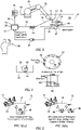
- the reflected wave signal is transformed into scan data 30 relayed in the form of an electrical signal 18 by the transducer 14 and relayed to a first processor 32 and displayed on a screen 16 (Computer 1 in Fig. 2 ).
- a second processor 34 (Computer 2 in Fig. 2 ) is configured to automatically analyze the scan data 30 to distinguish between actual part defects and spurious indications of defects.
- the first processor 32 is responsible for multiple functions. One of those functions includes sending scan plan information 36 to a robot controller 38.
- the first processor 32 can communicate with a motor controller 40.
- the motor controller 40 is configured to operate a motor 42 to rotate a turntable 44 supporting the inspected part 26.
- the first processor 32 can also receive scan signal data 30 from the pulser/receiver 12 received from the transducer 14 coupled to a robot 46 to be displayed for review by an inspector 48.
- the scan plan 36 contains instructions 50 for moving a robotic arm 52 and positioning the transducer 14 around the inspected part 26 for collection of scan data 30.
- the data 30 can be collected by scanning every surface 54 of the part 26 until the totality of surfaces 54 of the part 26 that cover the entirety of the part 26 volume have been scanned.
- the inspector 48 configures the scan by setting parameters 56 in a UT tank vendor software 58 installed on the first processor 32.
- the values of such parameters 56 depend on the inspected part 26; some parameters 56 and their representative values include water path length, that is, the distance between the tip of the transducer 14 and the inspected part 26 of for example, 100 mm.
- the pulser/receiver 12 produces outgoing electrical pulses 18 to the transducer 14 and receives/amplifies returning pulses 18 from the transducer 14.
- the robotic arm 52 aides in the translation (spatial coordinates) and angulation (tilting) of the transducer 14 according to the scan plan 36.
- a single transducer 14 generates and receives sound wave signals 20 that traverse the liquid medium 24 and the inspected part 26.
- the scanning procedure of one part surface 54 to generate the C-scan is depicted in Fig. 3 .
- a defect can be defined as a region of a material or a structure that has different physical properties from its neighborhood (causing a discontinuity in that region), and those differences in properties are not intended during manufacturing. Defects can occur during manufacturing or if the physical properties are altered over time.
- Some examples of defects detected by ultrasonic inspection are inclusions (e.g., non-metallic, metallic, reactive inclusions), or cracks.
- An indication is how those defects show up in the signals coming out from the immersion pulse-echo ultrasonic system.
- A-scan presentation is a one dimension, 1-D plot that displays the amount of received ultrasonic energy (vertical axis) as a function of time (horizontal axis).
- the B-scan presentation is a cross-sectional, two dimension, 2-D profile of the time-offlight (time travel or depth) of the sound energy in the vertical axis and the linear position of the transducer 14 in the horizontal axis.
- the C-scan presentation is also a 2-D plot that captures a plan-type view of the location and size of the part; plots for either relative signal amplitude or timeof-flight may be generated. Multiple presentation scans can be used together for more accurate determinations of the condition of the part 26.
- Detection of the subsurface defects 28 from the inspection data 30 is primarily performed by human inspectors 48 which is a labor intensive and error prone process leading to inconsistencies and cost of poor quality.
- Fig. 5(b) shows a system and method for automatic defect recognition (ADR) processor 66 for automatic inspection of engine parts 26 using immersion pulse-echo inspection technology as described above.
- the automatic defect recognition processor 66 can include one or more processors 66 (e.g., computer systems having a central processing unit and memory) for recording, processing and storing the data received.
- the processor 66 may include a general-purpose processor, a digital signal processor (DSP), an application specific integrated circuit (ASIC), a field programmable gate array (FPGA) or other programmable logic device, discrete gate or transistor logic, discrete hardware components, or any combination thereof.
- DSP digital signal processor
- ASIC application specific integrated circuit
- FPGA field programmable gate array
- the process is shown in Fig. 6 where the ADR processor 66 uses the communication with Sonic Tank block 68 to initiate the collection of data 30 from the inspection of the part 26 in the tank 22.
- the ADR processor 66 runs an indication (potential flaws) flaw detection algorithm 70 based on at least one inspection technique sheet 72.
- the ADR processor 66 further provides instructions to the transducer 14 to maximize a signal-to-noise ratio to localize identified indications more accurately.
- the indications can represent a sensed flaw or defect or discontinuity 28 in the part 26.
- a technique sheet 72 can be provided as an external input to the ADR processor 66 through the technique sheet specs block 74.
- the ADR processor 66 can issue a part level disposition 78 and automatically fills out quality notification (QN) reports 80 that can be communicated to the Factory 4.0 at block 82 for storage and archiving in quality databases 84 of the factory infrastructure 86.
- QN quality notification
- the ADR processor 66 can involve the human inspector 48 for assistance or/and verification of the detected indications 88. This is accomplished based on a confidence system that the ADR processor uses to self-assess its own disposition. The interaction of the human inspector with the ADR processor 66 is through a user interface 90.
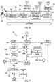
- FIG. 7 an exemplary automatic defect recognition system process flow diagram is shown.
- ADR processor 66 uses in the inspection process 92, C-scans and A-scans as detailed above.
- Fig. 7 shows the detailed flow of the processing of those scans 94 and description of situations requiring human 48 intervention (Inform Operator Block).
- the inspection process 92 starts at 96 by analyzing the C scan data for quality issues (for example, electrical noise, bubbles in the tank and the like). If the data is good, ADR processor 66 executes an algorithm to identify indications in the scan data at 98. At this point a second quality detector (per indication quality detector) 100 uses the A-scan associated with the identified indications as additional data to identify quality issues in the data.
- quality issues for example, electrical noise, bubbles in the tank and the like.
- the process 92 goes into an error handling loop 102 to troubleshoot and resolve the data quality issues. If any of the scan data defects (resulting from 96 or 100) can be automatically resolved 102, then ADR processor 66 will send a command to the sonic tank 22 for resolving this issue (for instance, brushing the surface in case of a bubble issue). After the automatic resolution is executed successfully, ADR processor 66 will request a rescan 104 from the sonic tank 22.
- the ADR processor 66 will involve the operator 48 at block 106 in order to perform some physical action (for example, brush bubbles off the part 26) before ADR processor 66 requests a rescan at 104.
- some physical action for example, brush bubbles off the part 26
- the process 92 will go into the error state where ADR processor will stop the current part inspection and move on to the next part.
- error handling mechanisms that take care of network issues that may arise and impact the communication of the ADR processor 66 and the sonic tank 22.
- the indications are classified and sorted by severity at block 108. Indications are further confirmed at block 110 by collecting additional A-scan data at different angulations of the transducer 14. Finally, at 112 the disposition and confidence module assesses each confirmed indication and comes up with a disposition, for example reject the part as the amplitude of at least one indication is above prescribed rejection threshold.
- An exemplary characteristic of the ADR processor 66 is the built-in confidence system 114 shown in "Disposition and Confidence Assessment" module 112 in Fig. 7 .
- the confidence 114 in ADR processor 66 disposition is a combination of subject-matter- experts (SME) that identify the features of interest 116 in a detected indication that can possibly be a defect 28, and machine learning methods 118 that use historical defect characteristics 120 to get bounds that determine likelihood of an indication 122 to be a real subsurface defect as shown in Fig. 8 .
- This knowledge provides the basis of the confidence system 114 that can provide a disposition such as high confidence pass/fail or low confidence pass/fail of the inspected part 26.
- the indication confidence model 122 depicted in Fig. 8 provides two outputs: 1) confidence: low or high and 2) a priority score which is a real number that provides a closeness metric of the evaluated indication to those indications from the historical training set 120.
- one metric that can be used as a priority score is a p-value of the statistical model learned by the machine learning (ML) process 118.
- the machine learning procedure 118 learns a statistical distribution function for the values , (for example, fitting mean and standard deviations of a multi-variate Gaussian distribution).
- a statistical distribution function for the values , (for example, fitting mean and standard deviations of a multi-variate Gaussian distribution).
- p-value 2Prob [Z>
- Fig. 9 provides a visual interpretation 122 of the p-value on a 1-D feature.
- the confidence/prioritization model 114 can be described from a statistical standpoint.
- a technical advantage of the process described for the confidence/scoring system 114 can be used for historical data analysis 120 to rank probability of a scanned part to have an ADR indication that is a real defect, hence human inspector 48 resources can be used efficiently for re-inspection purposes.
- Another technical advantage of the disclosed process can include an efficient automated process which minimizes user involvement and invokes that only when necessary.
- Another technical advantage of the disclosed process can include a unique method for confidence assessment along with indication scoring framework which allows for prioritization of user attention.
Landscapes
- Physics & Mathematics (AREA)
- General Physics & Mathematics (AREA)
- Pathology (AREA)
- Immunology (AREA)
- Health & Medical Sciences (AREA)
- Life Sciences & Earth Sciences (AREA)
- Chemical & Material Sciences (AREA)
- Analytical Chemistry (AREA)
- Biochemistry (AREA)
- General Health & Medical Sciences (AREA)
- Engineering & Computer Science (AREA)
- Acoustics & Sound (AREA)
- Signal Processing (AREA)
- Mathematical Physics (AREA)
- Theoretical Computer Science (AREA)
- Software Systems (AREA)
- Evolutionary Computation (AREA)
- Artificial Intelligence (AREA)
- Computer Vision & Pattern Recognition (AREA)
- Pure & Applied Mathematics (AREA)
- Mathematical Optimization (AREA)
- Data Mining & Analysis (AREA)
- Medical Informatics (AREA)
- Mathematical Analysis (AREA)
- Computing Systems (AREA)
- General Engineering & Computer Science (AREA)
- Algebra (AREA)
- Investigating Or Analyzing Materials By The Use Of Ultrasonic Waves (AREA)
Abstract
Description
- The present disclosure (invention) is directed to the improved process of automatic defect recognition for the automatic inspection of engine parts using immersion pulse-echo inspection technology.
- Aerospace engine components, may incur defects or imperfections during the manufacturing process. Non- destructive testing (NDT) inspections are performed during different stages of the manufacturing process to identify defective parts. Inspection methods include, but are not limited to, visual inspection, X- Ray, thermography, and ultrasonic testing. It is particularly difficult to inspect components that have an internal structure using only external observations. Forms of flaws such as porosity and inclusions in metallic parts are particularly difficult to detect. These types of defects can grow and damage the part in service. Such internal defects are often detected by some form of excitation of the structure (ultrasonic, thermoacoustic, and the like), sensing of the excitation, and manual interpretation of the sensor signals, see for example
Fig. 1 . This manual inspection process is tedious, time consuming, and error prone. - What is needed are automated or aided methods for detecting defects.
- In accordance with the present invention, there is provided a system for detecting a sub-surface defect comprising a transducer fluidly coupled to a part located in a tank containing a liquid configured to transmit ultrasonic energy, the transducer configured to scan the part to create scan data of the scanned part; a pulser/receiver coupled to the transducer configured to receive and transmit the scan data; a processor in electronic communication with the pulser/receiver, the processor configured to communicate with the pulser/receiver and collect the scan data; and the processor configured to detect the subsurface defect; a tangible, non-transitory memory configured to communicate with the processor, the tangible, non-transitory memory having instructions stored therein that, in response to execution by the processor, cause the processor to perform operations comprising: receiving, by the processor, the scan data for the part from the transducer; running, by the processor, a flaw detection algorithm; determining, by the processor, a part disposition; the part disposition is based on a confidence system that the processor uses to self-assess the part disposition; and creating, by the processor, a report.
- Optionally, the scan comprises transmitting ultrasonic energy to the part and receiving the ultrasonic energy from the part.
- Optionally, the flaw detection algorithm is based on at least one inspection technique sheet.
- Optionally, determining the part disposition is responsive to at least one of acceptance criteria defined in the technique sheet and the scan data.
- Optionally, the system further comprises providing, by the processor, further instructions to the transducer to maximize a signal-to-noise ratio to localize identified indications, wherein the indications represent at least one of a sensed flaw, defect, and discontinuity in the part.
- In accordance with the present invention, there is provided a system comprising a computer readable storage device readable by the system, tangibly embodying a program having a set of instructions executable by the system to perform the following steps for detecting a sub-surface defect, the set of instructions comprising: an instruction to receive scan data for a part from a transducer; an instruction to run a flaw detection algorithm; an instruction to determine a part disposition based on a confidence system that the processor uses to self-assess said part disposition; and an instruction to create a report.
- Optionally, the scan data is selected from at least one of C-scans and A-scans.
- Optionally, the flaw detection algorithm is based on at least one inspection technique sheet.
- Optionally, the instruction to determine the part disposition is responsive to at least one of acceptance criteria defined in the technique sheet and the scan data.
- Optionally, the system further comprises an instruction to the transducer to maximize a signal-to-noise ratio to localize identified indications, wherein the indications represent at least one of a sensed flaw, defect, and discontinuity in the part.
- In accordance with the present invention, there is provided a process for detecting a sub-surface defect by use of a system including a transducer fluidly coupled to a part located in a tank containing a liquid configured to transmit ultrasonic energy, the transducer configured to scan the part to create scan data of the scanned part; a pulser/receiver coupled to the transducer configured to receive and transmit the scan data; a processor coupled to the pulser/receiver, the processor configured to communicate with the pulser/receiver and collect the scan data; and the processor configured to detect the subsurface defect, a tangible, non-transitory memory configured to communicate with the processor, the tangible, non-transitory memory having instructions stored therein that, in response to execution by the processor, cause the processor to perform operations comprising: receiving, by the processor, the scan data for the part from the transducer, wherein the scan data comprises at least one of C-scan data and A-scan data; running, by the processor, a flaw detection algorithm; determining, by the processor, a part disposition; and creating, by the processor, a report.
- Optionally, the process further comprises: analyzing, by the processor, C-scan data for quality issues, wherein upon an indication that the C-scan data is acceptable, the processor executes an algorithm to identify indications in the scan data.
- Optionally, the process further comprises: analyzing, by the processor, an A-scan associated with the indication as additional scan data to identify quality issues in the scan data.
- Optionally, the process further comprises: detecting, by the processor, that at least one of the C-scan data and the A-scan data is bad, executing, by the processor, an error handling loop to troubleshoot and resolve the quality issues in the scan data.
- Optionally, the process further comprises: detecting, by the processor, that both of the C-scan data and the A-scan data are good, the indication is classified and sorted by a severity value.
- Optionally, the process further comprises: confirming, by the processor, the indication by collecting additional A-scan data at different angulations of the transducer.
- Optionally, the process further comprises: assessing, by the processor, a confirmed indication and providing a disposition for the indication; wherein the disposition comprises a combination of subject-matter- experts that identify features of interest in a detected indication that can be a defect, and a machine learning method that uses historical defect characteristics to get bounds that determine a likelihood of an indication to be a subsurface defect.
- Other details of the process are set forth in the following detailed description and the accompanying drawings wherein like reference numerals depict like elements.
-
-
Fig. 1 is a schematic of an exemplary manual inspection system. -
Fig. 2 is a schematic of an exemplary ultrasonic testing inspection system. -
Fig. 3 is a schematic of an exemplary ultrasonic testing inspection system. -
Fig. 4 is a schematic of exemplary surface scanning data generation. -
Figs. 5(a) and 5(b) is a schematic comparison of a human based inspection system and an exemplary automatic defect recognition system. -
Fig. 6 is a schematic of exemplary automatic defect recognition system modules. -
Fig. 7 is a schematic of an exemplary automatic defect recognition system workflow. -
Fig. 8 is a schematic of an exemplary automatic defect recognition system indication confidence model. -
Fig. 9 is a schematic of an exemplary machine learning model and p-value for a 1-D feature. - Referring now to
Fig. 2 , the exemplary ultrasonic testing (UT)inspection system 10 is shown. TheUT inspection system 10 includes several functional units, such as a pulser/receiver 12,transducer 14, anddisplay devices 16. A pulser/receiver 12 is an electronic device that can produce high voltageelectrical pulses 18. Driven by thepulser 12, thetransducer 14 generates high frequency ultrasonic energy (sound energy) 20. Thesound energy 20 is introduced and propagates in the form of waves through the materials in theUT tank 22, such aswater 24, and the part being inspected 26, like an engine disk. When there is adiscontinuity 28 in thepart 26, such as a crack, located in the wave path, a portion of theenergy 20 will be reflected back from thediscontinuity 28 surface. Thetransducer 14 can detect the reflected energy wave. The reflected wave signal is transformed intoscan data 30 relayed in the form of anelectrical signal 18 by thetransducer 14 and relayed to afirst processor 32 and displayed on a screen 16 (Computer 1 inFig. 2 ). A second processor 34 (Computer 2 inFig. 2 ) is configured to automatically analyze thescan data 30 to distinguish between actual part defects and spurious indications of defects. - A more detailed schematic of the interactions between
first processor 32 and theUT tank 22 is shown inFig. 3 . Thefirst processor 32 is responsible for multiple functions. One of those functions includes sendingscan plan information 36 to arobot controller 38. Thefirst processor 32 can communicate with amotor controller 40. Themotor controller 40 is configured to operate amotor 42 to rotate aturntable 44 supporting the inspectedpart 26. Thefirst processor 32 can also receivescan signal data 30 from the pulser/receiver 12 received from thetransducer 14 coupled to arobot 46 to be displayed for review by aninspector 48. - The
scan plan 36 containsinstructions 50 for moving arobotic arm 52 and positioning thetransducer 14 around the inspectedpart 26 for collection ofscan data 30. Thedata 30 can be collected by scanning everysurface 54 of thepart 26 until the totality ofsurfaces 54 of thepart 26 that cover the entirety of thepart 26 volume have been scanned. In order to generate ascan plan 36, theinspector 48 configures the scan by settingparameters 56 in a UT tank vendor software 58 installed on thefirst processor 32. The values ofsuch parameters 56 depend on theinspected part 26; someparameters 56 and their representative values include water path length, that is, the distance between the tip of thetransducer 14 and theinspected part 26 of for example, 100 mm. - The pulser/
receiver 12 produces outgoingelectrical pulses 18 to thetransducer 14 and receives/amplifies returningpulses 18 from thetransducer 14. Therobotic arm 52 aides in the translation (spatial coordinates) and angulation (tilting) of thetransducer 14 according to thescan plan 36. Asingle transducer 14 generates and receivessound wave signals 20 that traverse theliquid medium 24 and the inspectedpart 26. - Referring also to
Fig. 4 , the scan resolution in bothindex axis dimension 60 andscanning axis dimension 62 is shown. In an exemplary embodiment, a value of 0.5 mm each, ascan direction 64 of moving thetransducer 14 from the outer diameter (O.D.) to the inner diameter (I.D.) of theinspected part 26, the rotation speed of theturntable 44 supporting thepart 26, of for example 15 mm/s, and the gate (that is, an electronic means of selecting a segment of the time base range for monitoring or further processing) start and end positions of for example 5 mm and 30 mm, respectively, as well as its trigger level of 50% (that is, amplitude level above or below which the inspectedpart 26 is accepted or rejected) can be predetermined. The scanning procedure of onepart surface 54 to generate the C-scan is depicted inFig. 3 . - One of the main uses of the
UT inspection system 10 is for detecting and evaluating flaws or defects inphysical parts 26, such as turbine components of gas turbine engines. A defect can be defined as a region of a material or a structure that has different physical properties from its neighborhood (causing a discontinuity in that region), and those differences in properties are not intended during manufacturing. Defects can occur during manufacturing or if the physical properties are altered over time. Some examples of defects detected by ultrasonic inspection are inclusions (e.g., non-metallic, metallic, reactive inclusions), or cracks. An indication is how those defects show up in the signals coming out from the immersion pulse-echo ultrasonic system. Not all indications detected are defects because there might be false positives, but the premise from the inspection method is that all defects conforming to NDT specifications are detected as indications. Defect identification is performed by scanningparts 26 by pulser/receiver 12,transducer 14, anddisplay devices Ultrasonic data 30 of the scannedpart 26 can be formatted into three presentations: A-scan, B-scan, and C-scan. The A-scan presentation is a one dimension, 1-D plot that displays the amount of received ultrasonic energy (vertical axis) as a function of time (horizontal axis). The B-scan presentation is a cross-sectional, two dimension, 2-D profile of the time-offlight (time travel or depth) of the sound energy in the vertical axis and the linear position of thetransducer 14 in the horizontal axis. Lastly, the C-scan presentation is also a 2-D plot that captures a plan-type view of the location and size of the part; plots for either relative signal amplitude or timeof-flight may be generated. Multiple presentation scans can be used together for more accurate determinations of the condition of thepart 26. - Referring also to
Figs. 5a , an illustration of theinspection system 10, is shown. The sensitivity and the detection capability of thesystem 10 can be a result of the technology used for generating the inspection data. Detection of thesubsurface defects 28 from theinspection data 30 is primarily performed byhuman inspectors 48 which is a labor intensive and error prone process leading to inconsistencies and cost of poor quality. -
Fig. 5(b) shows a system and method for automatic defect recognition (ADR)processor 66 for automatic inspection ofengine parts 26 using immersion pulse-echo inspection technology as described above. The automaticdefect recognition processor 66 can include one or more processors 66 (e.g., computer systems having a central processing unit and memory) for recording, processing and storing the data received. Theprocessor 66 may include a general-purpose processor, a digital signal processor (DSP), an application specific integrated circuit (ASIC), a field programmable gate array (FPGA) or other programmable logic device, discrete gate or transistor logic, discrete hardware components, or any combination thereof. - The process is shown in
Fig. 6 where theADR processor 66 uses the communication withSonic Tank block 68 to initiate the collection ofdata 30 from the inspection of thepart 26 in thetank 22. After the data collection, theADR processor 66 runs an indication (potential flaws)flaw detection algorithm 70 based on at least oneinspection technique sheet 72. TheADR processor 66 further provides instructions to thetransducer 14 to maximize a signal-to-noise ratio to localize identified indications more accurately. The indications can represent a sensed flaw or defect ordiscontinuity 28 in thepart 26. Atechnique sheet 72 can be provided as an external input to theADR processor 66 through the technique sheet specs block 74. Using the acceptance criteria defined in thetechnique sheet 72 and detectedindications data 30, atblock 76 theADR processor 66 can issue apart level disposition 78 and automatically fills out quality notification (QN) reports 80 that can be communicated to the Factory 4.0 atblock 82 for storage and archiving inquality databases 84 of thefactory infrastructure 86. At certain points during the inspection, theADR processor 66 can involve thehuman inspector 48 for assistance or/and verification of the detectedindications 88. This is accomplished based on a confidence system that the ADR processor uses to self-assess its own disposition. The interaction of the human inspector with theADR processor 66 is through auser interface 90. - Referring also to
Fig. 7 , an exemplary automatic defect recognition system process flow diagram is shown. There can be two types of data thatADR processor 66 uses in theinspection process 92, C-scans and A-scans as detailed above.Fig. 7 shows the detailed flow of the processing of thosescans 94 and description of situations requiring human 48 intervention (Inform Operator Block). Theinspection process 92 starts at 96 by analyzing the C scan data for quality issues (for example, electrical noise, bubbles in the tank and the like). If the data is good,ADR processor 66 executes an algorithm to identify indications in the scan data at 98. At this point a second quality detector (per indication quality detector) 100 uses the A-scan associated with the identified indications as additional data to identify quality issues in the data. - If one of the quality detectors flags the data as bad, the
process 92 goes into anerror handling loop 102 to troubleshoot and resolve the data quality issues. If any of the scan data defects (resulting from 96 or 100) can be automatically resolved 102, thenADR processor 66 will send a command to thesonic tank 22 for resolving this issue (for instance, brushing the surface in case of a bubble issue). After the automatic resolution is executed successfully,ADR processor 66 will request arescan 104 from thesonic tank 22. On the other hand, if the scan data defects cannot be resolved automatically or the there was an issue with automatically resolving it, theADR processor 66 will involve theoperator 48 atblock 106 in order to perform some physical action (for example, brush bubbles off the part 26) beforeADR processor 66 requests a rescan at 104. In the case where the operator cannot resolve the issue or did not respond on time (at "Wait for operator" blocks), theprocess 92 will go into the error state where ADR processor will stop the current part inspection and move on to the next part. There are other error handling mechanisms that take care of network issues that may arise and impact the communication of theADR processor 66 and thesonic tank 22. - If both quality detectors pass the data, the indications are classified and sorted by severity at
block 108. Indications are further confirmed atblock 110 by collecting additional A-scan data at different angulations of thetransducer 14. Finally, at 112 the disposition and confidence module assesses each confirmed indication and comes up with a disposition, for example reject the part as the amplitude of at least one indication is above prescribed rejection threshold. - An exemplary characteristic of the
ADR processor 66 is the built-inconfidence system 114 shown in "Disposition and Confidence Assessment"module 112 inFig. 7 . Theconfidence 114 inADR processor 66 disposition is a combination of subject-matter- experts (SME) that identify the features ofinterest 116 in a detected indication that can possibly be adefect 28, andmachine learning methods 118 that usehistorical defect characteristics 120 to get bounds that determine likelihood of anindication 122 to be a real subsurface defect as shown inFig. 8 . This knowledge provides the basis of theconfidence system 114 that can provide a disposition such as high confidence pass/fail or low confidence pass/fail of the inspectedpart 26. Theindication confidence model 122 depicted inFig. 8 provides two outputs: 1) confidence: low or high and 2) a priority score which is a real number that provides a closeness metric of the evaluated indication to those indications from thehistorical training set 120. - In an exemplary embodiment one metric that can be used as a priority score is a p-value of the statistical model learned by the machine learning (ML)
process 118. For a given number N of features (N-dimensional features), using thehistorical inspection data 120, themachine learning procedure 118 learns a statistical distribution function for the values , (for example, fitting mean and standard deviations of a multi-variate Gaussian distribution). For an observed indication with feature values equal to Z0, one can use the p-value defined as p-value = 2Prob [Z>|z0|] as a measure of how close this indication is to a real defect model learned using ML. The higher the p-value, the closer the indication features are to the feature learned by the ML model, hence the closer the value is to a real defect or discontinuity. As an illustration for the p-value metric,Fig. 9 provides avisual interpretation 122 of the p-value on a 1-D feature. - The confidence/
prioritization model 114 can be described from a statistical standpoint. One can utilize themachine learning 118 process to learn a model for defects as a function of their features value; setup a null hypothesis (H0): ADR detected indication follows the ML distribution; test the statistic: features values; the threshold of significance: define confidence threshold (for example, 0.05); observation o: an indication detected by theADR system 66; Calculate p-value of observation O; reject the null hypothesis if the calculated p-value is below the threshold of significance and mark the indication as low confidence, or else accept the null hypothesis and mark the indication as high confidence. - A technical advantage of the process described for the confidence/
scoring system 114 can be used forhistorical data analysis 120 to rank probability of a scanned part to have an ADR indication that is a real defect, hencehuman inspector 48 resources can be used efficiently for re-inspection purposes. - Another technical advantage of the disclosed process can include an efficient automated process which minimizes user involvement and invokes that only when necessary.
- Another technical advantage of the disclosed process can include a unique method for confidence assessment along with indication scoring framework which allows for prioritization of user attention.
- There has been provided a process. While the process has been described in the context of specific embodiments thereof, other unforeseen alternatives, modifications, and variations may become apparent to those skilled in the art having read the foregoing description. Accordingly, it is intended to embrace those alternatives, modifications, and variations which fall within the broad scope of the appended claims.
Claims (15)
- A system for detecting a sub-surface defect (28) comprising:a transducer (14) fluidly coupled to a part (26) located in a tank (22) containing a liquid (24) configured to transmit ultrasonic energy (20), said transducer (14) configured to scan said part to create scan data (30) of the scanned part (26);a pulser/receiver (12) coupled to said transducer (14) configured to receive and transmit said scan data (30);a processor (32) in electronic communication with said pulser/receiver (12), said processor (32) configured to communicate with said pulser/receiver (12) and collect said scan data (30); and said processor (32) configured to detect said sub-surface defect (28);a tangible, non-transitory memory configured to communicate with said processor (32), the tangible, non-transitory memory having instructions stored therein that, in response to execution by the processor (32), cause the processor to perform operations comprising:receiving, by the processor (32), said scan data (30) for said part from said transducer (14);running, by the processor (32), a flaw detection algorithm;determining, by the processor (32), a part disposition wherein said part disposition is based on a confidence system (114) that the processor uses to self-assess said part disposition; andcreating, by the processor (32), a report.
- The system according to claim 1, wherein the scan comprises transmitting ultrasonic energy (20) to said part (26) and receiving said ultrasonic energy (20) from said part (26).
- The system according to claim 1 or 2, wherein said flaw detection algorithm is based on at least one inspection technique sheet (72) and wherein, optionally, determining said part disposition is responsive to at least one of acceptance criteria defined in the technique sheet (72) and the scan data (30) .
- The system according to claim 1, 2 or 3, further comprising:
providing, by the processor, further instructions to the transducer (14) to maximize a signal-to-noise ratio to localize identified indications, wherein the indications represent at least one of a sensed flaw, defect, and discontinuity (28) in the part (26). - A system comprising a computer readable storage device readable by the system, tangibly embodying a program having a set of instructions executable by the system to perform the following steps for detecting a sub-surface defect (28), the set of instructions comprising:an instruction to receive scan data (30) for a part from a transducer (14);an instruction to run a flaw detection algorithm;an instruction to determine a part disposition based on a confidence system (114) that the processor (32) uses to self-assess said part disposition; andan instruction to create a report.
- The system according to claim 5, wherein said scan data (30) is selected from at least one of C-scans and A-scans.
- The system according to claim 5 or 6, wherein said flaw detection algorithm is based on at least one inspection technique sheet (72) and
wherein, optionally, the instruction to determine said part disposition is responsive to at least one of acceptance criteria defined in the technique sheet (72) and the scan data (30). - The system according to claim 5, 6 or 7, further comprising:
an instruction to the transducer (14) to maximize a signal-to-noise ratio to localize identified indications, wherein the indications represent at least one of a sensed flaw, defect, and discontinuity (28) in the part (26). - A process for detecting a sub-surface defect by use of a system including a transducer (14) fluidly coupled to a part located in a tank (22) containing a liquid (24) configured to transmit ultrasonic energy (20), said transducer (14) configured to scan said part (26) to create scan data (30) of the scanned part (26); a pulser/receiver (12) coupled to said transducer (14) configured to receive and transmit said scan data (30); a processor (32) coupled to said pulser/receiver (12), said processor (32) configured to communicate with said pulser/receiver (12) and collect said scan data (30); and said processor (32) configured to detect said sub-surface defect (28), a tangible, non-transitory memory configured to communicate with said processor (32), the tangible, non-transitory memory having instructions stored therein that, in response to execution by the processor (32), cause the processor (32) to perform operations comprising:receiving, by the processor (32), said scan data (30) for said part (26) from said transducer (32), wherein said scan data (30) comprises at least one of C-scan data and A-scan data;running, by the processor (32), a flaw detection algorithm;determining, by the processor (32), a part disposition; andcreating, by the processor (32), a report.
- The process according to claim 9, further comprising:
analyzing, by the processor (32), C-scan data for quality issues, wherein upon an indication that said C-scan data is acceptable, the processor executes an algorithm to identify indications in the scan data (30). - The process according to claim 9 or 10, further comprising:
analyzing, by the processor (32), an A-scan associated with the indication as additional scan data (30) to identify quality issues in the scan data (30). - The process according to claim 9, 10 or 11, further comprising:
detecting, by the processor (32), that at least one of the C-scan data and the A-scan data is bad, executing, by the processor (32), an error handling loop to troubleshoot and resolve the quality issues in the scan data (30). - The process according to any of claims 9 to 12, further comprising:
detecting, by the processor (32), that both of the C-scan data and the A-scan data are good, the indication is classified and sorted by a severity value. - The process according to any of claims 9 to 13 further comprising:
confirming, by the processor (32), the indication by collecting additional A-scan data at different angulations of the transducer (14). - The process according to any of claims 9 to 14, further comprising:
assessing, by the processor (32), a confirmed indication and providing a disposition for the indication; wherein the disposition comprises a combination of subject-matter- experts that identify features of interest in a detected indication that can be a defect (38), and a machine learning method that uses historical defect characteristics to get bounds that determine a likelihood of an indication to be a subsurface defect (28).
Applications Claiming Priority (1)
| Application Number | Priority Date | Filing Date | Title |
|---|---|---|---|
| US17/352,964 US11913911B2 (en) | 2021-06-21 | 2021-06-21 | System and method for dual pulse-echo sub-surface detection |
Publications (3)
| Publication Number | Publication Date |
|---|---|
| EP4109089A2 true EP4109089A2 (en) | 2022-12-28 |
| EP4109089A3 EP4109089A3 (en) | 2023-01-25 |
| EP4109089B1 EP4109089B1 (en) | 2025-09-03 |
Family
ID=82160281
Family Applications (1)
| Application Number | Title | Priority Date | Filing Date |
|---|---|---|---|
| EP22180255.6A Active EP4109089B1 (en) | 2021-06-21 | 2022-06-21 | System and method for pulse-echo sub-surface detection |
Country Status (2)
| Country | Link |
|---|---|
| US (1) | US11913911B2 (en) |
| EP (1) | EP4109089B1 (en) |
Families Citing this family (1)
| Publication number | Priority date | Publication date | Assignee | Title |
|---|---|---|---|---|
| EP4703722A1 (en) * | 2024-09-03 | 2026-03-04 | Georg Fischer Rohrleitungssysteme AG | Weld evaluation |
Family Cites Families (18)
| Publication number | Priority date | Publication date | Assignee | Title |
|---|---|---|---|---|
| US3228234A (en) | 1963-01-02 | 1966-01-11 | Gen Electric | Ultrasonic inspection method |
| US4805459A (en) | 1988-02-29 | 1989-02-21 | Aerospace Testing Lab, Inc. | Ultrasonic testing method |
| US5445029A (en) | 1993-11-08 | 1995-08-29 | General Electric Co. | Calibration and flaw detection method for ultrasonic inspection of acoustically noisy materials |
| US7132617B2 (en) | 2002-02-20 | 2006-11-07 | Daimlerchrysler Corporation | Method and system for assessing quality of spot welds |
| EP1742047B1 (en) | 2004-04-26 | 2021-03-31 | Kabushiki Kaisha Toshiba | 3d ultrasonographic device |
| US7234354B2 (en) * | 2004-12-03 | 2007-06-26 | General Electric Company | Ultrasonic probe and inspection method and system |
| CA2593894C (en) | 2006-12-01 | 2016-11-08 | Roentgen Technische Dienst B.V. | A method for configuring an array of transducers in an ultrasonic test apparatus |
| DE102008002450B4 (en) | 2008-04-11 | 2022-06-23 | Waygate Technologies Usa, Lp | Method for the non-destructive testing of a test object using ultrasound and device for this |
| US9482645B2 (en) | 2013-05-17 | 2016-11-01 | General Electric Company | Ultrasonic detection method and ultrasonic analysis method |
| US11347191B2 (en) | 2015-07-29 | 2022-05-31 | Illinois Tool Works Inc. | System and method to facilitate welding software as a service |
| US10761066B2 (en) * | 2016-06-24 | 2020-09-01 | Kbr Wyle Services, Llc | Micro-resolution ultrasonic nondestructive imaging method |
| US10118111B2 (en) | 2016-08-13 | 2018-11-06 | The Boeing Company | Apparatus, system, and method for removing gas in an immersion ultrasonic process |
| US10875125B2 (en) | 2017-06-20 | 2020-12-29 | Lincoln Global, Inc. | Machine learning for weldment classification and correlation |
| US10928362B2 (en) | 2018-05-04 | 2021-02-23 | Raytheon Technologies Corporation | Nondestructive inspection using dual pulse-echo ultrasonics and method therefor |
| US11467129B2 (en) * | 2020-03-23 | 2022-10-11 | Olympus NDT Canada Inc. | NDT data referencing system |
| US11686707B2 (en) * | 2020-03-30 | 2023-06-27 | Verifi Technologies, Llc | System and method for real-time visualization of defects in a material |
| US20220018811A1 (en) * | 2020-07-14 | 2022-01-20 | Saudi Arabian Oil Company | Machine learning method for the denoising of ultrasound scans of composite slabs and pipes |
| US12203897B2 (en) * | 2021-03-01 | 2025-01-21 | Ecole De Technologie Superieure | Ultrasonic testing for defect detection |
-
2021
- 2021-06-21 US US17/352,964 patent/US11913911B2/en active Active
-
2022
- 2022-06-21 EP EP22180255.6A patent/EP4109089B1/en active Active
Also Published As
| Publication number | Publication date |
|---|---|
| US11913911B2 (en) | 2024-02-27 |
| US20220404319A1 (en) | 2022-12-22 |
| EP4109089A3 (en) | 2023-01-25 |
| EP4109089B1 (en) | 2025-09-03 |
Similar Documents
| Publication | Publication Date | Title |
|---|---|---|
| US7299697B2 (en) | Method and system for inspecting objects using ultrasound scan data | |
| US20090301202A1 (en) | Non-destructive testing, in particular for pipes during manufacture or in the finished state | |
| CN101903771A (en) | Especially for non-destructive testing of tubes during manufacture or in the finished state | |
| US11467129B2 (en) | NDT data referencing system | |
| CN101672829A (en) | Method for measuring parameter of omega welding seam defect | |
| EP4269999A1 (en) | Ultrasonic tomography method and system for evaluating pipeline corrosion | |
| CN117686588B (en) | Nondestructive monitoring system and method for welding quality of gas pipeline | |
| EP4109088B1 (en) | Automated scan data quality assessment in ultrasonic testing | |
| CN115930851A (en) | A method and device for detecting the melting width of a T-shaped electron beam weld | |
| EP4109089B1 (en) | System and method for pulse-echo sub-surface detection | |
| JP5150302B2 (en) | Ultrasonic inspection data evaluation apparatus and ultrasonic inspection data evaluation method | |
| US12265059B2 (en) | System and method for automated indication confirmation in ultrasonic testing | |
| KR101658122B1 (en) | Method and apparatus for displaying on a screen the state of welded sections measured using ultrasonic waves | |
| CN118641628A (en) | Ultrasonic testing method, nondestructive testing device and trajectory test block | |
| CN113899785A (en) | Detection method for lithium battery based on ultrasonic and infrared flaw detection | |
| JP7242579B2 (en) | Ultrasonic flaw detection system and ultrasonic flaw detection method | |
| KR102962535B1 (en) | System and method for nondestructive inspecting of water pipeline with ict | |
| CN119027419B (en) | Petroleum pipeline weld defect detection method based on image processing | |
| CN121476425B (en) | A cloud-based nondestructive testing data processing method | |
| US20260092898A1 (en) | Automated method and system for ultrasonically inspecting components | |
| Chen et al. | Research on ultrasonic TOFD scanning image weld defect detection method based on PyTorch | |
| US20260092897A1 (en) | Automated method and system for ultrasonically inspecting components | |
| JP5111588B2 (en) | Structural member inspection apparatus and structural member inspection method | |
| JP7455046B2 (en) | Underwater inspection equipment and underwater inspection method | |
| JP2002162390A (en) | Ultrasonic inspection apparatus and method |
Legal Events
| Date | Code | Title | Description |
|---|---|---|---|
| PUAI | Public reference made under article 153(3) epc to a published international application that has entered the european phase |
Free format text: ORIGINAL CODE: 0009012 |
|
| STAA | Information on the status of an ep patent application or granted ep patent |
Free format text: STATUS: THE APPLICATION HAS BEEN PUBLISHED |
|
| PUAL | Search report despatched |
Free format text: ORIGINAL CODE: 0009013 |
|
| AK | Designated contracting states |
Kind code of ref document: A2 Designated state(s): AL AT BE BG CH CY CZ DE DK EE ES FI FR GB GR HR HU IE IS IT LI LT LU LV MC MK MT NL NO PL PT RO RS SE SI SK SM TR |
|
| AK | Designated contracting states |
Kind code of ref document: A3 Designated state(s): AL AT BE BG CH CY CZ DE DK EE ES FI FR GB GR HR HU IE IS IT LI LT LU LV MC MK MT NL NO PL PT RO RS SE SI SK SM TR |
|
| RIC1 | Information provided on ipc code assigned before grant |
Ipc: G01N 29/44 20060101ALI20221220BHEP Ipc: G01N 29/11 20060101ALI20221220BHEP Ipc: G01N 29/07 20060101ALI20221220BHEP Ipc: G01N 29/06 20060101ALI20221220BHEP Ipc: G01N 29/04 20060101AFI20221220BHEP |
|
| STAA | Information on the status of an ep patent application or granted ep patent |
Free format text: STATUS: REQUEST FOR EXAMINATION WAS MADE |
|
| 17P | Request for examination filed |
Effective date: 20230724 |
|
| RBV | Designated contracting states (corrected) |
Designated state(s): AL AT BE BG CH CY CZ DE DK EE ES FI FR GB GR HR HU IE IS IT LI LT LU LV MC MK MT NL NO PL PT RO RS SE SI SK SM TR |
|
| RAP3 | Party data changed (applicant data changed or rights of an application transferred) |
Owner name: RTX CORPORATION |
|
| GRAP | Despatch of communication of intention to grant a patent |
Free format text: ORIGINAL CODE: EPIDOSNIGR1 |
|
| STAA | Information on the status of an ep patent application or granted ep patent |
Free format text: STATUS: GRANT OF PATENT IS INTENDED |
|
| INTG | Intention to grant announced |
Effective date: 20250303 |
|
| GRAS | Grant fee paid |
Free format text: ORIGINAL CODE: EPIDOSNIGR3 |
|
| RIN1 | Information on inventor provided before grant (corrected) |
Inventor name: EL CHAMIE, MAHMOUD Inventor name: SURANA, AMIT Inventor name: SCHULZE, CHRISTOPH Inventor name: ELKFRAWY, AYMAN Inventor name: BRANTLEY, JR., MATTHEW L. Inventor name: ERDINC, OZGUR |
|
| GRAA | (expected) grant |
Free format text: ORIGINAL CODE: 0009210 |
|
| STAA | Information on the status of an ep patent application or granted ep patent |
Free format text: STATUS: THE PATENT HAS BEEN GRANTED |
|
| AK | Designated contracting states |
Kind code of ref document: B1 Designated state(s): AL AT BE BG CH CY CZ DE DK EE ES FI FR GB GR HR HU IE IS IT LI LT LU LV MC MK MT NL NO PL PT RO RS SE SI SK SM TR |
|
| REG | Reference to a national code |
Ref country code: CH Ref legal event code: EP |
|
| REG | Reference to a national code |
Ref country code: DE Ref legal event code: R096 Ref document number: 602022020577 Country of ref document: DE |
|
| REG | Reference to a national code |
Ref country code: IE Ref legal event code: FG4D |
|
| REG | Reference to a national code |
Ref country code: NL Ref legal event code: MP Effective date: 20250903 |
|
| PG25 | Lapsed in a contracting state [announced via postgrant information from national office to epo] |
Ref country code: NO Free format text: LAPSE BECAUSE OF FAILURE TO SUBMIT A TRANSLATION OF THE DESCRIPTION OR TO PAY THE FEE WITHIN THE PRESCRIBED TIME-LIMIT Effective date: 20251203 |
|
| REG | Reference to a national code |
Ref country code: LT Ref legal event code: MG9D |
|
| PG25 | Lapsed in a contracting state [announced via postgrant information from national office to epo] |
Ref country code: FI Free format text: LAPSE BECAUSE OF FAILURE TO SUBMIT A TRANSLATION OF THE DESCRIPTION OR TO PAY THE FEE WITHIN THE PRESCRIBED TIME-LIMIT Effective date: 20250903 |
|
| PG25 | Lapsed in a contracting state [announced via postgrant information from national office to epo] |
Ref country code: HR Free format text: LAPSE BECAUSE OF FAILURE TO SUBMIT A TRANSLATION OF THE DESCRIPTION OR TO PAY THE FEE WITHIN THE PRESCRIBED TIME-LIMIT Effective date: 20250903 |
|
| PG25 | Lapsed in a contracting state [announced via postgrant information from national office to epo] |
Ref country code: GR Free format text: LAPSE BECAUSE OF FAILURE TO SUBMIT A TRANSLATION OF THE DESCRIPTION OR TO PAY THE FEE WITHIN THE PRESCRIBED TIME-LIMIT Effective date: 20251204 |
|
| PG25 | Lapsed in a contracting state [announced via postgrant information from national office to epo] |
Ref country code: SE Free format text: LAPSE BECAUSE OF FAILURE TO SUBMIT A TRANSLATION OF THE DESCRIPTION OR TO PAY THE FEE WITHIN THE PRESCRIBED TIME-LIMIT Effective date: 20250903 |
|
| PG25 | Lapsed in a contracting state [announced via postgrant information from national office to epo] |
Ref country code: LV Free format text: LAPSE BECAUSE OF FAILURE TO SUBMIT A TRANSLATION OF THE DESCRIPTION OR TO PAY THE FEE WITHIN THE PRESCRIBED TIME-LIMIT Effective date: 20250903 |
|
| PG25 | Lapsed in a contracting state [announced via postgrant information from national office to epo] |
Ref country code: BG Free format text: LAPSE BECAUSE OF FAILURE TO SUBMIT A TRANSLATION OF THE DESCRIPTION OR TO PAY THE FEE WITHIN THE PRESCRIBED TIME-LIMIT Effective date: 20250903 Ref country code: PL Free format text: LAPSE BECAUSE OF FAILURE TO SUBMIT A TRANSLATION OF THE DESCRIPTION OR TO PAY THE FEE WITHIN THE PRESCRIBED TIME-LIMIT Effective date: 20250903 |
|
| PG25 | Lapsed in a contracting state [announced via postgrant information from national office to epo] |
Ref country code: RS Free format text: LAPSE BECAUSE OF FAILURE TO SUBMIT A TRANSLATION OF THE DESCRIPTION OR TO PAY THE FEE WITHIN THE PRESCRIBED TIME-LIMIT Effective date: 20251203 |
|
| PG25 | Lapsed in a contracting state [announced via postgrant information from national office to epo] |
Ref country code: ES Free format text: LAPSE BECAUSE OF FAILURE TO SUBMIT A TRANSLATION OF THE DESCRIPTION OR TO PAY THE FEE WITHIN THE PRESCRIBED TIME-LIMIT Effective date: 20250903 |
|
| REG | Reference to a national code |
Ref country code: AT Ref legal event code: MK05 Ref document number: 1833604 Country of ref document: AT Kind code of ref document: T Effective date: 20250903 |
|
| PG25 | Lapsed in a contracting state [announced via postgrant information from national office to epo] |
Ref country code: NL Free format text: LAPSE BECAUSE OF FAILURE TO SUBMIT A TRANSLATION OF THE DESCRIPTION OR TO PAY THE FEE WITHIN THE PRESCRIBED TIME-LIMIT Effective date: 20250903 |
|
| PG25 | Lapsed in a contracting state [announced via postgrant information from national office to epo] |
Ref country code: SM Free format text: LAPSE BECAUSE OF FAILURE TO SUBMIT A TRANSLATION OF THE DESCRIPTION OR TO PAY THE FEE WITHIN THE PRESCRIBED TIME-LIMIT Effective date: 20250903 |
|
| PG25 | Lapsed in a contracting state [announced via postgrant information from national office to epo] |
Ref country code: AT Free format text: LAPSE BECAUSE OF FAILURE TO SUBMIT A TRANSLATION OF THE DESCRIPTION OR TO PAY THE FEE WITHIN THE PRESCRIBED TIME-LIMIT Effective date: 20250903 |
|
| PG25 | Lapsed in a contracting state [announced via postgrant information from national office to epo] |
Ref country code: IT Free format text: LAPSE BECAUSE OF FAILURE TO SUBMIT A TRANSLATION OF THE DESCRIPTION OR TO PAY THE FEE WITHIN THE PRESCRIBED TIME-LIMIT Effective date: 20250903 |
|
| PG25 | Lapsed in a contracting state [announced via postgrant information from national office to epo] |
Ref country code: IS Free format text: LAPSE BECAUSE OF FAILURE TO SUBMIT A TRANSLATION OF THE DESCRIPTION OR TO PAY THE FEE WITHIN THE PRESCRIBED TIME-LIMIT Effective date: 20260103 |
|
| PG25 | Lapsed in a contracting state [announced via postgrant information from national office to epo] |
Ref country code: PT Free format text: LAPSE BECAUSE OF FAILURE TO SUBMIT A TRANSLATION OF THE DESCRIPTION OR TO PAY THE FEE WITHIN THE PRESCRIBED TIME-LIMIT Effective date: 20260105 Ref country code: CZ Free format text: LAPSE BECAUSE OF FAILURE TO SUBMIT A TRANSLATION OF THE DESCRIPTION OR TO PAY THE FEE WITHIN THE PRESCRIBED TIME-LIMIT Effective date: 20250903 |
|
| PG25 | Lapsed in a contracting state [announced via postgrant information from national office to epo] |
Ref country code: SK Free format text: LAPSE BECAUSE OF FAILURE TO SUBMIT A TRANSLATION OF THE DESCRIPTION OR TO PAY THE FEE WITHIN THE PRESCRIBED TIME-LIMIT Effective date: 20250903 Ref country code: EE Free format text: LAPSE BECAUSE OF FAILURE TO SUBMIT A TRANSLATION OF THE DESCRIPTION OR TO PAY THE FEE WITHIN THE PRESCRIBED TIME-LIMIT Effective date: 20250903 |