EP4108908A1 - Main beam for fan blade and manufacturing method therefor - Google Patents
Main beam for fan blade and manufacturing method therefor Download PDFInfo
- Publication number
- EP4108908A1 EP4108908A1 EP20919545.2A EP20919545A EP4108908A1 EP 4108908 A1 EP4108908 A1 EP 4108908A1 EP 20919545 A EP20919545 A EP 20919545A EP 4108908 A1 EP4108908 A1 EP 4108908A1
- Authority
- EP
- European Patent Office
- Prior art keywords
- carbon fiber
- main beam
- inlays
- resin
- fiber pultruded
- Prior art date
- Legal status (The legal status is an assumption and is not a legal conclusion. Google has not performed a legal analysis and makes no representation as to the accuracy of the status listed.)
- Granted
Links
Images

Classifications
-
- F—MECHANICAL ENGINEERING; LIGHTING; HEATING; WEAPONS; BLASTING
- F03—MACHINES OR ENGINES FOR LIQUIDS; WIND, SPRING, OR WEIGHT MOTORS; PRODUCING MECHANICAL POWER OR A REACTIVE PROPULSIVE THRUST, NOT OTHERWISE PROVIDED FOR
- F03D—WIND MOTORS
- F03D1/00—Wind motors with rotation axis substantially parallel to the air flow entering the rotor
- F03D1/06—Rotors
- F03D1/065—Rotors characterised by their construction elements
- F03D1/0675—Rotors characterised by their construction elements of the blades
-
- B—PERFORMING OPERATIONS; TRANSPORTING
- B29—WORKING OF PLASTICS; WORKING OF SUBSTANCES IN A PLASTIC STATE IN GENERAL
- B29C—SHAPING OR JOINING OF PLASTICS; SHAPING OF MATERIAL IN A PLASTIC STATE, NOT OTHERWISE PROVIDED FOR; AFTER-TREATMENT OF THE SHAPED PRODUCTS, e.g. REPAIRING
- B29C70/00—Shaping composites, i.e. plastics material comprising reinforcements, fillers or preformed parts, e.g. inserts
- B29C70/04—Shaping composites, i.e. plastics material comprising reinforcements, fillers or preformed parts, e.g. inserts comprising reinforcements only, e.g. self-reinforcing plastics
- B29C70/06—Fibrous reinforcements only
- B29C70/10—Fibrous reinforcements only characterised by the structure of fibrous reinforcements, e.g. hollow fibres
- B29C70/16—Fibrous reinforcements only characterised by the structure of fibrous reinforcements, e.g. hollow fibres using fibres of substantial or continuous length
-
- B—PERFORMING OPERATIONS; TRANSPORTING
- B29—WORKING OF PLASTICS; WORKING OF SUBSTANCES IN A PLASTIC STATE IN GENERAL
- B29C—SHAPING OR JOINING OF PLASTICS; SHAPING OF MATERIAL IN A PLASTIC STATE, NOT OTHERWISE PROVIDED FOR; AFTER-TREATMENT OF THE SHAPED PRODUCTS, e.g. REPAIRING
- B29C70/00—Shaping composites, i.e. plastics material comprising reinforcements, fillers or preformed parts, e.g. inserts
- B29C70/04—Shaping composites, i.e. plastics material comprising reinforcements, fillers or preformed parts, e.g. inserts comprising reinforcements only, e.g. self-reinforcing plastics
- B29C70/28—Shaping operations therefor
- B29C70/40—Shaping or impregnating by compression not applied
- B29C70/50—Shaping or impregnating by compression not applied for producing articles of indefinite length, e.g. prepregs, sheet moulding compounds [SMC] or cross moulding compounds [XMC]
- B29C70/52—Pultrusion, i.e. forming and compressing by continuously pulling through a die
-
- B—PERFORMING OPERATIONS; TRANSPORTING
- B29—WORKING OF PLASTICS; WORKING OF SUBSTANCES IN A PLASTIC STATE IN GENERAL
- B29D—PRODUCING PARTICULAR ARTICLES FROM PLASTICS OR FROM SUBSTANCES IN A PLASTIC STATE
- B29D99/00—Subject matter not provided for in other groups of this subclass
- B29D99/0025—Producing blades or the like, e.g. blades for turbines, propellers, or wings
-
- B—PERFORMING OPERATIONS; TRANSPORTING
- B29—WORKING OF PLASTICS; WORKING OF SUBSTANCES IN A PLASTIC STATE IN GENERAL
- B29K—INDEXING SCHEME ASSOCIATED WITH SUBCLASSES B29B, B29C OR B29D, RELATING TO MOULDING MATERIALS OR TO MATERIALS FOR MOULDS, REINFORCEMENTS, FILLERS OR PREFORMED PARTS, e.g. INSERTS
- B29K2307/00—Use of elements other than metals as reinforcement
- B29K2307/04—Carbon
-
- B—PERFORMING OPERATIONS; TRANSPORTING
- B29—WORKING OF PLASTICS; WORKING OF SUBSTANCES IN A PLASTIC STATE IN GENERAL
- B29K—INDEXING SCHEME ASSOCIATED WITH SUBCLASSES B29B, B29C OR B29D, RELATING TO MOULDING MATERIALS OR TO MATERIALS FOR MOULDS, REINFORCEMENTS, FILLERS OR PREFORMED PARTS, e.g. INSERTS
- B29K2309/00—Use of inorganic materials not provided for in groups B29K2303/00 - B29K2307/00, as reinforcement
- B29K2309/08—Glass
-
- B—PERFORMING OPERATIONS; TRANSPORTING
- B29—WORKING OF PLASTICS; WORKING OF SUBSTANCES IN A PLASTIC STATE IN GENERAL
- B29L—INDEXING SCHEME ASSOCIATED WITH SUBCLASS B29C, RELATING TO PARTICULAR ARTICLES
- B29L2031/00—Other particular articles
- B29L2031/08—Blades for rotors, stators, fans, turbines or the like, e.g. screw propellers
- B29L2031/082—Blades, e.g. for helicopters
- B29L2031/085—Wind turbine blades
-
- F—MECHANICAL ENGINEERING; LIGHTING; HEATING; WEAPONS; BLASTING
- F05—INDEXING SCHEMES RELATING TO ENGINES OR PUMPS IN VARIOUS SUBCLASSES OF CLASSES F01-F04
- F05B—INDEXING SCHEME RELATING TO WIND, SPRING, WEIGHT, INERTIA OR LIKE MOTORS, TO MACHINES OR ENGINES FOR LIQUIDS COVERED BY SUBCLASSES F03B, F03D AND F03G
- F05B2230/00—Manufacture
- F05B2230/30—Manufacture with deposition of material
-
- F—MECHANICAL ENGINEERING; LIGHTING; HEATING; WEAPONS; BLASTING
- F05—INDEXING SCHEMES RELATING TO ENGINES OR PUMPS IN VARIOUS SUBCLASSES OF CLASSES F01-F04
- F05B—INDEXING SCHEME RELATING TO WIND, SPRING, WEIGHT, INERTIA OR LIKE MOTORS, TO MACHINES OR ENGINES FOR LIQUIDS COVERED BY SUBCLASSES F03B, F03D AND F03G
- F05B2280/00—Materials; Properties thereof
- F05B2280/60—Properties or characteristics given to material by treatment or manufacturing
- F05B2280/6003—Composites; e.g. fibre-reinforced
-
- F—MECHANICAL ENGINEERING; LIGHTING; HEATING; WEAPONS; BLASTING
- F05—INDEXING SCHEMES RELATING TO ENGINES OR PUMPS IN VARIOUS SUBCLASSES OF CLASSES F01-F04
- F05B—INDEXING SCHEME RELATING TO WIND, SPRING, WEIGHT, INERTIA OR LIKE MOTORS, TO MACHINES OR ENGINES FOR LIQUIDS COVERED BY SUBCLASSES F03B, F03D AND F03G
- F05B2280/00—Materials; Properties thereof
- F05B2280/60—Properties or characteristics given to material by treatment or manufacturing
- F05B2280/6013—Fibres
-
- Y—GENERAL TAGGING OF NEW TECHNOLOGICAL DEVELOPMENTS; GENERAL TAGGING OF CROSS-SECTIONAL TECHNOLOGIES SPANNING OVER SEVERAL SECTIONS OF THE IPC; TECHNICAL SUBJECTS COVERED BY FORMER USPC CROSS-REFERENCE ART COLLECTIONS [XRACs] AND DIGESTS
- Y02—TECHNOLOGIES OR APPLICATIONS FOR MITIGATION OR ADAPTATION AGAINST CLIMATE CHANGE
- Y02E—REDUCTION OF GREENHOUSE GAS [GHG] EMISSIONS, RELATED TO ENERGY GENERATION, TRANSMISSION OR DISTRIBUTION
- Y02E10/00—Energy generation through renewable energy sources
- Y02E10/70—Wind energy
- Y02E10/72—Wind turbines with rotation axis in wind direction
-
- Y—GENERAL TAGGING OF NEW TECHNOLOGICAL DEVELOPMENTS; GENERAL TAGGING OF CROSS-SECTIONAL TECHNOLOGIES SPANNING OVER SEVERAL SECTIONS OF THE IPC; TECHNICAL SUBJECTS COVERED BY FORMER USPC CROSS-REFERENCE ART COLLECTIONS [XRACs] AND DIGESTS
- Y02—TECHNOLOGIES OR APPLICATIONS FOR MITIGATION OR ADAPTATION AGAINST CLIMATE CHANGE
- Y02P—CLIMATE CHANGE MITIGATION TECHNOLOGIES IN THE PRODUCTION OR PROCESSING OF GOODS
- Y02P70/00—Climate change mitigation technologies in the production process for final industrial or consumer products
- Y02P70/50—Manufacturing or production processes characterised by the final manufactured product
Definitions
- the present invention generally relates to the field of wind turbine, in particular, to a main beam for wind turbine blade. Furthermore, the present invention relates to a method for manufacturing this main beam.
- the blades of the wind turbine are important components of the wind turbine to capture wind energy.
- the blades installed on the wind turbine hub are rotated by wind energy to generate lift, which is further converted into torque through the transmission chain in the nacelle to drive the generator to generate electricity.
- the larger the impeller composed of blades the more wind energy can be captured, so the blades of the wind turbine tend to be longer and longer.
- the blade main beam is the component that contributes about 90% of the swing stiffness, which basically determines the size of the headroom.
- Carbon fiber is a high-modulus, high-strength material, but at the same time, it is expensive. Therefore, how to reasonably introduce carbon fibers into the blades to increase the headroom margin and minimize the cost of the blades is an important research topic for major wind power companies. Due to the high cost of the pure carbon fiber main beam and the long time to return the cost of one-time investment, a variety of hybrid carbon fiber materials emerge as the times require. Hybrid carbon fiber materials are formed by adding a certain amount of carbon fiber to traditional glass fiber materials. Hybrid carbon fiber materials may try to balance performance and cost.
- the current hybrid carbon fiber materials mainly have the following limitations:
- the mixing method of hybrid carbon fiber materials is mostly carried out at the material scale. For example, carbon fiber and glass fiber are mixed and woven in the same fabric layer in different proportions of fiber bundles, or a layer of carbon fiber and a layer of glass fiber are mixed. This mixing manner is extremely lack of design freedom, and the proportion of fiber mixing is completely controlled by the material supplier. For different types of blades, only fixed mixing ratio materials can be selected, which cannot meet the needs of customization for each model.
- Carbon-glass hybrid materials that is, a mixture of carbon fiber and glass fiber
- an infusion process that is, multi-layered carbon-glass hybrid fabrics are superimposed and infused together, or several layers of carbon fiber and several layers of glass fiber cloth are superimposed and infused together.
- the infusion process of this material is prone to defects such as bubbles and wrinkles, which greatly compromise the final properties.
- a main beam for wind turbine blade comprising:
- main beam refers to the elongated structure on both sides of the blade for reinforcing the blade. Usually, the main beams on both sides are connected with webs located inside the blade to support the inner space of the blade.
- overlay refers to a structure with a certain shape embedded in the main beam.
- carbon fiber pultruded sheet refers to a material made of carbon fiber impregnated with an infusion material
- carbon fiber pultruded body refers to a composite body composed of a plurality of carbon fiber pultruded sheets and the infusion material between them.
- the inlay, the carbon fiber pultruded body in the main beam and the overlay form a continuous main beam surface, if necessary, having the desired curvature.
- the term "impregnate” refers to the infusing of an infusion material into an infusion object and at least partially bonding therewith and finally curing.
- the glass fiber infusion material between the carbon fiber pultruded sheets can be the second infusion material, that is, the infusing of the carbon fiber pultruded sheet and the infusing of the second infusion material can be performed in the same process, which can save the process.
- the glass fiber infusion material between the carbon fiber pultruded sheets may also be different from the second infusion material and be infused in a different process from the second infusion material.
- the carbon fiber pultruded sheets and inlays may be arranged adjacent to each other in a direction perpendicular to the thickness of the main beam, such as in the length and width directions of the main beam, to form the coverage area of the main beam.
- the carbon fiber pultruded sheets and the inlays are strip-like structures
- the carbon fiber pultruded sheets and the inlays may be arranged adjacent to each other in the chord direction of the main beam.
- chord direction refers to the direction perpendicular to the thickness of the main beam and perpendicular to the length of the blade.
- the one or more carbon fiber pultruded sheets comprise a plurality of carbon fiber pultruded sheets, and a glass fiber infusion material is provided between at least two of the plurality of carbon fiber pultruded sheets.
- the carbon fiber pultruded bodies has m of the carbon fiber pultruded sheets, and the main beam has n of the carbon fiber pultruded bodies, p of the inlays, and q of the overlays, wherein m, n, p, q are integers from 1 to 100.
- the one or more inlays may be placed on one or both sides of each of the carbon fiber pultruded bodies, respectively. Not only can the number of the inlays be adjusted, but also the stiffness and flexibility of the inlays can be adjusted to achieve the desired drapability after secondary infusion with the carbon fiber pultrude bodies to better form the desired curved surface.
- the first infusion material comprises one or more of the following: thermosetting epoxy resin, vinyl resin, unsaturated polyester resin, phenolic resin, and thermoplastic resin.
- thermosetting epoxy resin vinyl resin
- unsaturated polyester resin unsaturated polyester resin
- phenolic resin unsaturated polyester resin
- thermoplastic resin thermoplastic resin
- the thermoplastic resin comprises one or more of the following: polypropylene resin, polyethylene resin, polyvinyl chloride resin, polystyrene resin, acrylonitrile-butadiene-styrene copolymer resin, polyamide resin, polyetheretherketone resin, and polyphenylene sulfide resin.
- polypropylene resin polyethylene resin
- polyvinyl chloride resin polystyrene resin
- acrylonitrile-butadiene-styrene copolymer resin polyamide resin
- polyetheretherketone resin polyphenylene sulfide resin
- the overlay comprises glass fiber fabric or glass fiber non-woven fabric.
- the inlay comprises one or more of the following: PVC foam, PET foam, PMI foam, wood, honeycomb sandwich material, glass fiber pultruded sheet, glass fiber fabric, glass fiber non-woven fabric, and glass fiber yarn.
- PVC foam polyvinyl chloride
- PET foam PET foam
- PMI foam polymethyl methacrylate
- wood polymethyl methacrylate
- honeycomb sandwich material glass fiber pultruded sheet
- glass fiber fabric glass fiber non-woven fabric
- glass fiber yarn glass fiber yarn.
- Other inlay materials are also conceivable under the teachings of the present invention.
- the second infusion material comprises one or more of the following: thermosetting epoxy resin, vinyl resin, unsaturated polyester resin, phenolic resin, and thermoplastic resin.
- the thermoplastic resin comprises one or more of the following: polypropylene resin, polyethylene resin, polyvinyl chloride resin, polystyrene resin, acrylonitrile-butadiene-styrene copolymer resin, polyamide resin, polyetheretherketone resin, and polyphenylene sulfide resin.
- the inlays comprise:
- the overlays only need to cover the carbon fiber pultruded bodies, thereby providing more mobility in the thickness direction of the main beam; secondly, since the inlays are composed of the main body and the transition portion in the thickness direction of the main beam, more mobility is provided in the direction perpendicular to the thickness direction of the main beam, such as the chord direction; the mobility facilitates the formation of the desired surface shape, such as a curved surface, of the main beam material prior to infusing, and thus the surface shape can be cured and maintained after infusing.
- the cross-section of the main body of the inlays is rectangular and the cross-section of the transition portion of the inlays is triangular.
- different shapes of the main body of the inlays and the transition portion of the inlays can be adopted.
- the shape of the main body of the inlays and the transition portion of the inlays may be determined according to the desired final shape of the main beam.
- the foregoing object is solved by a method for manufacturing the main beam for wind turbine blade, the method comprises the following steps:
- arranging the one or more inlays adjacent to the carbon fiber pultruded bodies in the direction perpendicular to the thickness direction of the main beam comprises the following steps:
- the overlays only need to cover the carbon fiber pultruded bodies, thereby providing more mobility in the thickness direction of the main beam; secondly, since the inlays are composed of the main body and the transition in the thickness direction of the main beam, more mobility is provided in the direction perpendicular to the thickness direction of the main beam, such as the chord direction; the mobility facilitates the formation of the desired surface shape, such as a curved surface, of the main beam material prior to infusing, and thus can cure to maintain the surface shape after infusing.
- arranging the one or more inlays adjacent to the carbon fiber pultruded bodies in the direction perpendicular to the thickness direction of the main beam comprises the following steps: placing the inlays on both sides of each of the carbon fiber pultruded bodies to form a continuous composite.
- providing the one or more carbon fiber pultruded bodies comprises the following steps:
- the present invention has at least the following beneficial effects: (1) the invention better solves the problems of air bubbles and wrinkles in the carbon fiber mixed material through two infusions, that is, the infusion of the carbon fiber pultruded body and the infusion of the main beam. This is because in the present invention, only the carbon fiber pultruded body is formed by infusing multiple stacks, and the second infusion is mainly used for the secondary infusion of the infused carbon fiber pultruded body and the inlay. This process is less prone to bubbles and wrinkles, as significantly fewer layers are to be infused in this process compared to the prior art laminates in which carbon fiber sheets and glass fiber layers are arranged on top of each other.
- the carbon fiber pultruded body replaces most of the hybrid fiber stacks, the risk of defects such as air bubbles and wrinkles in the main beam is greatly reduced.
- the drapability of the main beam made is improved, so that it can better fit the mold and form a desired shape, such as a curved surface.
- the material, rigidity, flexibility, shape and other parameters of the inlay can be easily adjusted, various physical and dimensional characteristics of the main beam, such as rigidity, thickness, width, etc., can be easily and accurately adjusted.
- Carbon-glass mixing can be carried out at the scale of blade structure design, and is not restricted by material suppliers.
- the mixing ratio and form can be freely adjusted with different blade models.
- carbon fiber adopts pultrusion process
- glass fiber can be in the form of glass fiber cloth. Through secondary infusion and curing together, it is ensured that the carbon fiber is used in the form of pultrusion, thereby improving the performance of the main beam.
- the quantifiers "a” and “an” do not exclude the scenario of multiple elements.
- Fig. 1A shows a first embodiment according to the present invention.
- the main beam 100 comprises the following components:
- a carbon fiber pultruded body 11 which has a plurality of carbon fiber pultruded sheets 101a and a second infusion material 101b, wherein the carbon fiber pultruded sheets 101a are arranged to overlap each other in the thickness direction A of the main beam 100 and are spaced apart by the second infusion material 101b.
- the second infusion material 101b is, for example, glass fiber fabric or non-woven fabric.
- the glass fiber infusion material between the carbon fiber pultruded sheets 101a is the second infusion material 101b, that is to say, the infusion of the carbon fiber pultruded sheet 101a and the infusion of the second infusion material are the same process, which can save process.
- the glass fiber infusion material between the carbon fiber pultruded sheets 101a may also be different from the second infusion material 101b, and be infused in a different process from the second infusion material.
- the carbon fiber pultruded sheet 101a is, for example, formed by curing a certain amount of carbon fibers using a first infusion material (not shown).
- the first infusion material of the carbon fiber pultruded sheet 101b may comprise, for example, one or more of the following: thermosetting epoxy resin, vinyl resin, unsaturated polyester resin, phenolic resin, and thermoplastic resin.
- the thermoplastic resin may comprise, for example, one or more of the following: polypropylene resin, polyethylene resin, polyvinyl chloride resin, polystyrene resin, acrylonitrile-butadiene-styrene copolymer resin, polyamide resin, polyetheretherketone resin, and polyphenylene sulfide resin.
- An inlay 102 which is arranged adjacent to the carbon fiber pultruded body 101 in a direction perpendicular to the thickness direction of the main beam 100, such as the chord direction B of the main beam 100.
- chord direction refers to the direction perpendicular to the thickness of the main beam and perpendicular to the length of the blade.
- the inlay 102 is arranged between and flush with the two carbon fiber pultruded bodies 12.
- the inlay 102 may have a thickness difference with the carbon fiber pultruded body 12, and the thickness difference may be compensated for by the transition portion of the inlay or the overlay.
- the inlay 102 may comprise, for example, one or more of the following: PVC foam, PET foam, PMI foam, wood, honeycomb sandwich material, glass fiber pultruded sheet, glass fiber fabric, glass fiber non-woven fabric, and glass fiber yarn.
- Parameters of the inlay 102 such as material, rigidity, flexibility, shape, etc., can be adjusted according to the specific application, whereby various physical and dimensional characteristics of the main beam, such as rigidity, thickness, width, etc., can be easily and accurately adjusted.
- An overlay 103 which covers the carbon fiber pultruded body and/or the inlay on both sides of the main beam 100 in the thickness direction A.
- the overlay 103 may comprise, for example, a glass fiber fabric or a glass fiber nonwoven fabric.
- the overlay 103 is used, for example, to form the surface of the wind turbine blade and to protect the inner material from the external environment damage.
- two overlays 103 are shown, which cover both the carbon fiber pultruded body 101 and the inlay 102 on both sides of the main beam 100 in the thickness direction A, respectively.
- the overlay 103 may only cover the carbon fiber pultruded body 101.
- a second infusion material 101b which impregnates the carbon fiber pultruded bodies, the inlays and the overlays.
- the second infusion material may comprise, for example, one or more of the following: thermosetting epoxy resin, vinyl resin, unsaturated polyester resin, phenolic resin, and thermoplastic resin.
- the thermoplastic resin may comprise, for example, one or more of the following: polypropylene resin, polyethylene resin, polyvinyl chloride resin, polystyrene resin, acrylonitrile-butadiene-styrene copolymer resin, polyamide resin, polyetheretherketone resin, and polyphenylene sulfide resin.
- the main beam 100 By selecting the materials and properties of the inlay 102, the drapability of the main beam 100 can be improved while maintaining the rigidity of the main beam 100, and defects, such as air bubbles and wrinkles, in the main beam 100 can be basically avoided. Therefore, the main beam 100 according to the present invention has a great technical improvement compared to the conventional main beam.
- Fig. 1b shows a second embodiment according to the present invention.
- each inlay 102 has a smaller width than that in the first embodiment, thereby providing greater stiffness and better drapability.
- smaller width inlays 102 may also be arranged, thereby providing greater stiffness and better drapability.
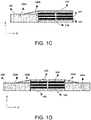
- Fig. 1C shows a third embodiment according to the present invention.
- the inlay 102 comprises:
- a main body of the inlay 102a the thickness d1 of which is smaller than the sum D of the thicknesses of the adjacent carbon fiber pultruded body 101 and the over 102.
- the cross section of main body of the inlay 102a may be rectangular, for example.
- the cross section of the transition portion of the inlay 102b is, for example, triangular.
- the overlay 103 By arranging the main body of the inlay 102a and the transition portion of the inlay 102b, a better drapability of the main beam can be achieved. This is because, first of all, in the case where there is an transition portion of the inlay 102b on the upper part of the inlay 102, the overlay 103 only needs to cover the carbon fiber pultruded body 101, thereby providing more mobility in the thickness direction A of the main beam 100; next, since the inlay 102 is composed of a plurality of parts of the main body of the inlay 102a and the transition portion of the inlay 102b in the thickness direction of the main beam 100, more mobility is provided in the direction perpendicular to the thickness direction of the main beam, such as the chord direction B of the main beam 100; these mobilities facilitate the formation of the desired surface shape, such as a curved surface, of the main beam material prior to infusion, so that curing after infusion maintains the surface shape.
- Fig. ID shows a fourth embodiment according to the present invention.
- the difference between the fourth embodiment and the third embodiment is that main body of the inlay 102a and transition portion of the inlay 102b are arranged on both sides of the carbon fiber pultruded body 101 to form a symmetrical shape transition.
- This symmetrical shape transition is favorable for forming a thickened portion of the material of the main beam, and the thickening portion is favorable for forming a special curved surface of the main beam or compensating for weak parts of the material.
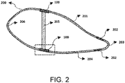
- Fig. 2 shows a schematic diagram of a wind turbine blade 200 employing the main beam 100 according to the present invention.
- the blade 200 has a leading edge 206 and a trailing edge 203.
- the part of the blade 200 between the leading edge 206 and the trailing edge 203 is divided into a windward side 201 and a leeward side 204.
- a trailing edge beam 202 is positioned near the trailing edge 203 to increase trailing edge strength.
- the main beam 100 is arranged on the windward side 201 and the leeward side 204, respectively, between the leading edge 206 of the blade and the trailing edge 203 of the blade.
- the main beams 100 are connected by webs 205 to increase the stability of the blade and prevent inward collapse.
- the rigidity of the blade 200 can be improved, and the drapability of the material of the main beam can be enhanced, thereby improving the aerodynamic performance and service life of the blade.
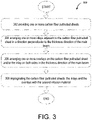
- Fig. 3 shows a process flow of a method 300 for manufacturing the main beam for wind turbine blade according to the present invention.
- each carbon fiber pultruded body comprising multiple carbon fiber pultruded sheets, the carbon fiber pultruded sheets are stacked in the thickness direction, wherein the carbon fiber pultruded sheets are formed by curing a first infusion material, wherein a glass fiber infusion material is arranged between every two carbon fiber pultruded sheets;
- step 304 arranging one or more inlays adjacent to the carbon fiber pultruded body in a direction perpendicular to the thickness direction of the main beam;
- step 306 arranging one or more overlays on the carbon fiber pultruded body and/or the inlay on both sides in the thickness direction of the main beam;
- step 308 impregnating the carbon fiber pultruded bodies, the inlays and the overlays with the second infusion material.
- the present invention has at least the following beneficial effects: (1) the invention better solves the problems of air bubbles and wrinkles in the carbon fiber mixed material through two infusions, that is, the infusion of the carbon fiber pultruded body and the infusion of the main beam. This is because in the present invention, only the carbon fiber pultruded body is formed by infusing multiple stacks, and the second infusion is mainly used for the secondary infusion of the infused carbon fiber pultruded body and the inlay. This process is less prone to bubbles and wrinkles, as significantly fewer layers are to be infused in this process compared to the prior art laminates in which carbon fiber sheets and glass fiber layers are arranged on top of each other.
- the carbon fiber pultruded body replaces most of the hybrid fiber stacks, the risk of defects such as air bubbles and wrinkles in the main beam is greatly reduced.
- the drapability of the main beam made is improved, so that it can better fit the mold and form a desired shape, such as a curved surface.
- the material, rigidity, flexibility, shape and other parameters of the inlay can be easily adjusted, various physical and dimensional characteristics of the main beam, such as rigidity, thickness, width, etc., can be easily and accurately adjusted.
- Carbon-glass mixing can be carried out at the scale of blade structure design, and is not restricted by material suppliers.
- the mixing ratio and form can be freely adjusted with different blade models.
- carbon fiber adopts pultrusion process
- glass fiber can be in the form of glass fiber cloth. Through secondary infusion and curing together, it is ensured that the carbon fiber is used in the form of pultrusion, thereby improving the performance of the main beam.
Landscapes
- Engineering & Computer Science (AREA)
- Mechanical Engineering (AREA)
- Chemical & Material Sciences (AREA)
- Sustainable Development (AREA)
- Life Sciences & Earth Sciences (AREA)
- Composite Materials (AREA)
- Sustainable Energy (AREA)
- Combustion & Propulsion (AREA)
- General Engineering & Computer Science (AREA)
- Textile Engineering (AREA)
- Moulding By Coating Moulds (AREA)
- Wind Motors (AREA)
- Structures Of Non-Positive Displacement Pumps (AREA)
Abstract
Description
- The present invention generally relates to the field of wind turbine, in particular, to a main beam for wind turbine blade. Furthermore, the present invention relates to a method for manufacturing this main beam.
- In recent years, as countries pay more attention to the environment, a rapid development trend is shown in the field of clean energy around the world. The clean energy, as a new type of energy, has the advantages of wide distribution, renewable energy and less environmental pollution compared with traditional fossil fuels. As the most potential representative of clean energy, the application of wind turbines is increasing and is expected to further replace traditional fossil energy.
- The blades of the wind turbine are important components of the wind turbine to capture wind energy. The blades installed on the wind turbine hub are rotated by wind energy to generate lift, which is further converted into torque through the transmission chain in the nacelle to drive the generator to generate electricity. Under the same circumstances, the larger the impeller composed of blades, the more wind energy can be captured, so the blades of the wind turbine tend to be longer and longer.
- As the blades get longer and longer, the headroom (the distance from the tip of the wind turbine blade to the tower, which is an important safety indicator) is becoming a bottleneck, and it is imperative to develop new blade materials or blade designs to improve the headroom. The blade main beam is the component that contributes about 90% of the swing stiffness, which basically determines the size of the headroom.
- Carbon fiber is a high-modulus, high-strength material, but at the same time, it is expensive. Therefore, how to reasonably introduce carbon fibers into the blades to increase the headroom margin and minimize the cost of the blades is an important research topic for major wind power companies. Due to the high cost of the pure carbon fiber main beam and the long time to return the cost of one-time investment, a variety of hybrid carbon fiber materials emerge as the times require. Hybrid carbon fiber materials are formed by adding a certain amount of carbon fiber to traditional glass fiber materials. Hybrid carbon fiber materials may try to balance performance and cost.
- However, the current hybrid carbon fiber materials mainly have the following limitations:
- 1. the mixing method of hybrid carbon fiber materials is mostly carried out at the material scale. For example, carbon fiber and glass fiber are mixed and woven in the same fabric layer in different proportions of fiber bundles, or a layer of carbon fiber and a layer of glass fiber are mixed. This mixing manner is extremely lack of design freedom, and the proportion of fiber mixing is completely controlled by the material supplier. For different types of blades, only fixed mixing ratio materials can be selected, which cannot meet the needs of customization for each model.
- 2. the final mechanical properties of carbon fiber are greatly affected by the process, so a stable process route is crucial to the performance stability of the final product. Carbon-glass hybrid materials (that is, a mixture of carbon fiber and glass fiber) generally use an infusion process, that is, multi-layered carbon-glass hybrid fabrics are superimposed and infused together, or several layers of carbon fiber and several layers of glass fiber cloth are superimposed and infused together. However, the infusion process of this material is prone to defects such as bubbles and wrinkles, which greatly compromise the final properties.
- There is a need for a new wind turbine main beam or main beam material that at least partially eliminates the above limitations.
- It is an object of the present invention to provide a main beam for wind turbine blade and a manufacturing method thereof, through the main beam and/or the method, various properties of the blade, such as stiffness, can be adjusted while reducing the amount of carbon fiber. At the same time, the drapability of the main beam to the curved mold is improved and defects such as bubbles and wrinkles are reduced, thereby improving the required stiffness and service life of the main beam.
- In a first aspect of the present invention, this object is solved by a main beam for wind turbine blade, comprising:
- one or more carbon fiber pultruded bodies, each of the carbon fiber pultruded bodies comprising one or more carbon fiber pultruded sheets, the carbon fiber pultruded sheets are stacked along a thickness direction of carbon fiber pultruded bodies, wherein the carbon fiber pultruded sheets are formed by curing a first infusion material;
- one or more inlays, which are arranged adjacent to the carbon fiber pultruded bodies in a direction perpendicular to a thickness direction of the main beam;
- one or more overlays, which cover the carbon fiber pultruded bodies and/or the inlays on both sides in the thickness direction of the main beam; and
- a second infusion material, which impregnates the carbon fiber pultruded bodies, the inlays and the overlays.
- In the context of the present invention, the term "main beam" refers to the elongated structure on both sides of the blade for reinforcing the blade. Usually, the main beams on both sides are connected with webs located inside the blade to support the inner space of the blade. The term "inlay" refers to a structure with a certain shape embedded in the main beam. The term "carbon fiber pultruded sheet" refers to a material made of carbon fiber impregnated with an infusion material, and the term "carbon fiber pultruded body" refers to a composite body composed of a plurality of carbon fiber pultruded sheets and the infusion material between them. Preferably, the inlay, the carbon fiber pultruded body in the main beam and the overlay form a continuous main beam surface, if necessary, having the desired curvature. The term "impregnate" refers to the infusing of an infusion material into an infusion object and at least partially bonding therewith and finally curing. In addition, the glass fiber infusion material between the carbon fiber pultruded sheets can be the second infusion material, that is, the infusing of the carbon fiber pultruded sheet and the infusing of the second infusion material can be performed in the same process, which can save the process. However, the glass fiber infusion material between the carbon fiber pultruded sheets may also be different from the second infusion material and be infused in a different process from the second infusion material. The carbon fiber pultruded sheets and inlays may be arranged adjacent to each other in a direction perpendicular to the thickness of the main beam, such as in the length and width directions of the main beam, to form the coverage area of the main beam. In the case where the carbon fiber pultruded sheets and the inlays are strip-like structures, the carbon fiber pultruded sheets and the inlays may be arranged adjacent to each other in the chord direction of the main beam. Here, the term "chord direction" refers to the direction perpendicular to the thickness of the main beam and perpendicular to the length of the blade.
- In a preferred embodiment of the present invention, the one or more carbon fiber pultruded sheets comprise a plurality of carbon fiber pultruded sheets, and a glass fiber infusion material is provided between at least two of the plurality of carbon fiber pultruded sheets.
- In an extended embodiment of the present invention, the carbon fiber pultruded bodies has m of the carbon fiber pultruded sheets, and the main beam has n of the carbon fiber pultruded bodies, p of the inlays, and q of the overlays, wherein m, n, p, q are integers from 1 to 100. For example, the one or more inlays may be placed on one or both sides of each of the carbon fiber pultruded bodies, respectively. Not only can the number of the inlays be adjusted, but also the stiffness and flexibility of the inlays can be adjusted to achieve the desired drapability after secondary infusion with the carbon fiber pultrude bodies to better form the desired curved surface.
- In an extended embodiment of the present invention, the first infusion material comprises one or more of the following: thermosetting epoxy resin, vinyl resin, unsaturated polyester resin, phenolic resin, and thermoplastic resin. Other infusion material is also conceivable under the teachings of the present invention.
- In an extended embodiment of the present invention, the thermoplastic resin comprises one or more of the following: polypropylene resin, polyethylene resin, polyvinyl chloride resin, polystyrene resin, acrylonitrile-butadiene-styrene copolymer resin, polyamide resin, polyetheretherketone resin, and polyphenylene sulfide resin. Other thermoplastic resin is also conceivable under the teachings of the present invention.
- In an extended embodiment of the present invention, the overlay comprises glass fiber fabric or glass fiber non-woven fabric.
- In an extended embodiment of the present invention, the inlay comprises one or more of the following: PVC foam, PET foam, PMI foam, wood, honeycomb sandwich material, glass fiber pultruded sheet, glass fiber fabric, glass fiber non-woven fabric, and glass fiber yarn. Other inlay materials are also conceivable under the teachings of the present invention.
- In an extended embodiment of the present invention, the second infusion material comprises one or more of the following: thermosetting epoxy resin, vinyl resin, unsaturated polyester resin, phenolic resin, and thermoplastic resin.
- In an extended embodiment of the present invention, the thermoplastic resin comprises one or more of the following: polypropylene resin, polyethylene resin, polyvinyl chloride resin, polystyrene resin, acrylonitrile-butadiene-styrene copolymer resin, polyamide resin, polyetheretherketone resin, and polyphenylene sulfide resin.
- In a preferred embodiment of the present invention, the inlays comprise:
- a main body of the inlays, the thickness d1 of which is less than or equal to the sum D of the thicknesses of the adjacent carbon fiber pultruded bodies and the overlays; and
- a transition portion of the inlays, the thickness d2 of which varies between zero and D-d1, wherein the transition portion of the inlays is arranged between the main body of the inlay and the adjacent carbon fiber pultruded bodies to form a thickness transition.
- Through this preferred embodiment, better drapability of the main beam can be achieved. The reason is that, firstly, when there is a transition portion on the upper part of the inlays, the overlays only need to cover the carbon fiber pultruded bodies, thereby providing more mobility in the thickness direction of the main beam; secondly, since the inlays are composed of the main body and the transition portion in the thickness direction of the main beam, more mobility is provided in the direction perpendicular to the thickness direction of the main beam, such as the chord direction; the mobility facilitates the formation of the desired surface shape, such as a curved surface, of the main beam material prior to infusing, and thus the surface shape can be cured and maintained after infusing.
- In an extended embodiment of the present invention, the cross-section of the main body of the inlays is rectangular and the cross-section of the transition portion of the inlays is triangular. According to different applications, different shapes of the main body of the inlays and the transition portion of the inlays can be adopted. For example, the shape of the main body of the inlays and the transition portion of the inlays may be determined according to the desired final shape of the main beam.
- In a second aspect of the present invention, the foregoing object is solved by a method for manufacturing the main beam for wind turbine blade, the method comprises the following steps:
- providing one or more carbon fiber pultruded bodies, each of the carbon fiber pultruded bodies comprising one or more carbon fiber pultruded sheets, the carbon fiber pultruded sheets are stacked along a thickness direction, wherein the carbon fiber pultruded sheets are formed by curing a first infusion material, wherein a glass fiber infusion material is arranged between every two of the carbon fiber pultruded sheets;
- arranging one or more inlays adjacent to the carbon fiber pultruded bodies in the direction perpendicular to the thickness direction of the main beam;
- arranging one or more overlays on the carbon fiber pultruded bodies and/or the inlays on both sides in the thickness direction of the main beam; and
- impregnating the carbon fiber pultruded bodies, the inlays and the overlays with a second infusion material.
- In a preferred embodiment of the present invention, arranging the one or more inlays adjacent to the carbon fiber pultruded bodies in the direction perpendicular to the thickness direction of the main beam comprises the following steps:
- disposing a main body of the inlays adjacent to the fiber pultruded bodies, wherein the thickness d1 of the main body of the inlays is less than or equal to the sum D of the thicknesses of the adjacent carbon fiber pultruded bodies and the overlays; and
- arranging a transition portion of the inlays between the main body of the inlays and the adjacent carbon fiber pultruded bodies to form the transition portion of the inlay with a thickness transition, wherein the thickness d2 of the transition of the inlays varies between zero and D-d1.
- Through this preferred embodiment, better drapability of the main beam can be achieved. The reason is that, firstly, when there is a transition on the upper part of the inlays, the overlays only need to cover the carbon fiber pultruded bodies, thereby providing more mobility in the thickness direction of the main beam; secondly, since the inlays are composed of the main body and the transition in the thickness direction of the main beam, more mobility is provided in the direction perpendicular to the thickness direction of the main beam, such as the chord direction; the mobility facilitates the formation of the desired surface shape, such as a curved surface, of the main beam material prior to infusing, and thus can cure to maintain the surface shape after infusing.
- In an extended embodiment of the present invention, arranging the one or more inlays adjacent to the carbon fiber pultruded bodies in the direction perpendicular to the thickness direction of the main beam comprises the following steps:
placing the inlays on both sides of each of the carbon fiber pultruded bodies to form a continuous composite. - In an extended embodiment of the present invention, providing the one or more carbon fiber pultruded bodies comprises the following steps:
- arranging one or more carbon fiber pultruded sheets stacked with each other along the thickness direction, wherein the carbon fiber pultruded sheets have been impregnated and cured with the first infusion material; and
- setting a glass fiber infusion layer between every two of the carbon fiber pultruded sheets for secondary infusion.
- The present invention has at least the following beneficial effects: (1) the invention better solves the problems of air bubbles and wrinkles in the carbon fiber mixed material through two infusions, that is, the infusion of the carbon fiber pultruded body and the infusion of the main beam. This is because in the present invention, only the carbon fiber pultruded body is formed by infusing multiple stacks, and the second infusion is mainly used for the secondary infusion of the infused carbon fiber pultruded body and the inlay. This process is less prone to bubbles and wrinkles, as significantly fewer layers are to be infused in this process compared to the prior art laminates in which carbon fiber sheets and glass fiber layers are arranged on top of each other. Since the carbon fiber pultruded body replaces most of the hybrid fiber stacks, the risk of defects such as air bubbles and wrinkles in the main beam is greatly reduced. (2) In the present invention, by laying the carbon fiber pultruded body and the inlay in contact with each other, the drapability of the main beam made is improved, so that it can better fit the mold and form a desired shape, such as a curved surface. (3) Since the material, rigidity, flexibility, shape and other parameters of the inlay can be easily adjusted, various physical and dimensional characteristics of the main beam, such as rigidity, thickness, width, etc., can be easily and accurately adjusted. (4) Carbon-glass mixing can be carried out at the scale of blade structure design, and is not restricted by material suppliers. The mixing ratio and form can be freely adjusted with different blade models. At the same time, carbon fiber adopts pultrusion process, and glass fiber can be in the form of glass fiber cloth. Through secondary infusion and curing together, it is ensured that the carbon fiber is used in the form of pultrusion, thereby improving the performance of the main beam.
- The present invention is further described below with reference to the accompanying drawings in conjunction with specific embodiments.
-
Fig. 1A- Fig.1D shows various embodiments of the main beams according to the present invention. -
Fig. 2 shows a schematic diagram of a wind turbine employing the main beam according to the present invention. -
Fig. 3 shows a process flow of a method for manufacturing the main beam for wind turbine blade according to the present invention. - It should be noted that various components in the various figures may be shown exaggerated for illustration purposes and not necessarily to correct scale. In the various figures, identical or functionally identical components are provided with the same reference numerals.
- In the present invention, unless otherwise specified, "arranged on," "arranged over," and "arranged over" do not exclude the case where there is an intermediate between the two. In addition, "arranged on or above" only means the relative positional relationship between two components, and in certain circumstances, such as after reversing the product direction, it can also be converted to "arranged under or below", and vice versa.
- In the present invention, each embodiment is only intended to illustrate the solution of the present invention, and should not be construed as limiting.
- In the present invention, unless otherwise specified, the quantifiers "a" and "an" do not exclude the scenario of multiple elements.
- It should also be pointed out here that, in the embodiments of the present invention, for the sake of clarity and simplicity, only a part of the components or assemblies may be shown, but those of ordinary skill in the art can understand that, under the teaching of the present invention, required parts or components may be added according to specific scenarios.
- It should also be pointed out that within the scope of the present invention, the terms "same", "equal" and "equal to" do not mean that the two values are absolutely equal, but allow a certain reasonable error, that is, the phrases also encompass "substantially the same", "substantially equal", "substantially equal to". By analogy, in the present invention, the terms "perpendicular to", "parallel to" and the like in the table direction also encompass the meanings of "substantially perpendicular to" and "substantially parallel to".
- In addition, the numbering of the steps of each method of the present invention does not limit the execution order of the method steps. Unless otherwise indicated, the various method steps may be performed in a different order.
- The present invention is further described below with reference to the accompanying drawings in conjunction with specific embodiments.
-
Fig. 1A shows a first embodiment according to the present invention. - In the first embodiment, the
main beam 100 has n carbon fiber pultrudedbodies 101, p inlays 102 and q overlays 103, where n=2, p=1, and q=2. It should be noted that the numbers of n, p, q are only exemplary, and in other embodiments, different values of n, p, q may also be set. - Specifically, the
main beam 100 comprises the following components: - A carbon fiber pultruded body 11, which has a plurality of carbon fiber pultruded
sheets 101a and asecond infusion material 101b, wherein the carbon fiber pultrudedsheets 101a are arranged to overlap each other in the thickness direction A of themain beam 100 and are spaced apart by thesecond infusion material 101b. Thesecond infusion material 101b is, for example, glass fiber fabric or non-woven fabric. In this embodiment, the glass fiber infusion material between the carbon fiber pultrudedsheets 101a is thesecond infusion material 101b, that is to say, the infusion of the carbon fiber pultrudedsheet 101a and the infusion of the second infusion material are the same process, which can save process. However, in other embodiments, the glass fiber infusion material between the carbon fiber pultrudedsheets 101a may also be different from thesecond infusion material 101b, and be infused in a different process from the second infusion material. Here, the carbon fiber pultrudedsheet 101a is, for example, formed by curing a certain amount of carbon fibers using a first infusion material (not shown). The first infusion material of the carbon fiber pultrudedsheet 101b may comprise, for example, one or more of the following: thermosetting epoxy resin, vinyl resin, unsaturated polyester resin, phenolic resin, and thermoplastic resin. The thermoplastic resin may comprise, for example, one or more of the following: polypropylene resin, polyethylene resin, polyvinyl chloride resin, polystyrene resin, acrylonitrile-butadiene-styrene copolymer resin, polyamide resin, polyetheretherketone resin, and polyphenylene sulfide resin. - An
inlay 102, which is arranged adjacent to the carbon fiber pultrudedbody 101 in a direction perpendicular to the thickness direction of themain beam 100, such as the chord direction B of themain beam 100. Here, the term "chord direction" refers to the direction perpendicular to the thickness of the main beam and perpendicular to the length of the blade. Here, theinlay 102 is arranged between and flush with the two carbon fiber pultruded bodies 12. In other embodiments, theinlay 102 may have a thickness difference with the carbon fiber pultruded body 12, and the thickness difference may be compensated for by the transition portion of the inlay or the overlay. Theinlay 102 may comprise, for example, one or more of the following: PVC foam, PET foam, PMI foam, wood, honeycomb sandwich material, glass fiber pultruded sheet, glass fiber fabric, glass fiber non-woven fabric, and glass fiber yarn. Parameters of theinlay 102, such as material, rigidity, flexibility, shape, etc., can be adjusted according to the specific application, whereby various physical and dimensional characteristics of the main beam, such as rigidity, thickness, width, etc., can be easily and accurately adjusted. - An
overlay 103, which covers the carbon fiber pultruded body and/or the inlay on both sides of themain beam 100 in the thickness direction A. Theoverlay 103 may comprise, for example, a glass fiber fabric or a glass fiber nonwoven fabric. Theoverlay 103 is used, for example, to form the surface of the wind turbine blade and to protect the inner material from the external environment damage. Here, twooverlays 103 are shown, which cover both the carbon fiber pultrudedbody 101 and theinlay 102 on both sides of themain beam 100 in the thickness direction A, respectively. In other embodiments, theoverlay 103 may only cover the carbon fiber pultrudedbody 101. - A
second infusion material 101b, which impregnates the carbon fiber pultruded bodies, the inlays and the overlays. The second infusion material may comprise, for example, one or more of the following: thermosetting epoxy resin, vinyl resin, unsaturated polyester resin, phenolic resin, and thermoplastic resin. The thermoplastic resin may comprise, for example, one or more of the following: polypropylene resin, polyethylene resin, polyvinyl chloride resin, polystyrene resin, acrylonitrile-butadiene-styrene copolymer resin, polyamide resin, polyetheretherketone resin, and polyphenylene sulfide resin. - By selecting the materials and properties of the
inlay 102, the drapability of themain beam 100 can be improved while maintaining the rigidity of themain beam 100, and defects, such as air bubbles and wrinkles, in themain beam 100 can be basically avoided. Therefore, themain beam 100 according to the present invention has a great technical improvement compared to the conventional main beam. -
Fig. 1b shows a second embodiment according to the present invention. - In the second embodiment, the
main beam 100 has n stacks of carbon fiber pultrudedbodies 101, p inlays 102 and q overlays 103, where n=3, p=3, q=2. It should be noted that the numbers of n, p, q are only exemplary, and in other embodiments, different values of n, p, q may also be set. - In the second embodiment, a plurality of
inlays 102 are arranged, and eachinlay 102 has a smaller width than that in the first embodiment, thereby providing greater stiffness and better drapability. In other embodiments, smaller width inlays 102 may also be arranged, thereby providing greater stiffness and better drapability. -
Fig. 1C shows a third embodiment according to the present invention. - In the third embodiment, the
inlay 102 comprises: - A main body of the
inlay 102a, the thickness d1 of which is smaller than the sum D of the thicknesses of the adjacent carbon fiber pultrudedbody 101 and the over 102. The cross section of main body of theinlay 102a may be rectangular, for example. - A transition portion of the
inlay 102b, the thickness d2 of which varies between zero and D-dl, where the transition portion of theinlay 102b is arranged between the main body of the inlay and the adjacent carbon fiber pultruded body to form a thickness transition. The cross section of the transition portion of theinlay 102b is, for example, triangular. - By arranging the main body of the
inlay 102a and the transition portion of theinlay 102b, a better drapability of the main beam can be achieved. This is because, first of all, in the case where there is an transition portion of theinlay 102b on the upper part of theinlay 102, theoverlay 103 only needs to cover the carbon fiber pultrudedbody 101, thereby providing more mobility in the thickness direction A of themain beam 100; next, since theinlay 102 is composed of a plurality of parts of the main body of theinlay 102a and the transition portion of theinlay 102b in the thickness direction of themain beam 100, more mobility is provided in the direction perpendicular to the thickness direction of the main beam, such as the chord direction B of themain beam 100; these mobilities facilitate the formation of the desired surface shape, such as a curved surface, of the main beam material prior to infusion, so that curing after infusion maintains the surface shape. - Fig. ID shows a fourth embodiment according to the present invention.
- The difference between the fourth embodiment and the third embodiment is that main body of the
inlay 102a and transition portion of theinlay 102b are arranged on both sides of the carbon fiber pultrudedbody 101 to form a symmetrical shape transition. This symmetrical shape transition is favorable for forming a thickened portion of the material of the main beam, and the thickening portion is favorable for forming a special curved surface of the main beam or compensating for weak parts of the material. -
Fig. 2 shows a schematic diagram of awind turbine blade 200 employing themain beam 100 according to the present invention. - As shown in
Fig. 2 , theblade 200 has aleading edge 206 and a trailingedge 203. The part of theblade 200 between theleading edge 206 and the trailingedge 203 is divided into awindward side 201 and aleeward side 204. A trailingedge beam 202 is positioned near the trailingedge 203 to increase trailing edge strength. Themain beam 100 is arranged on thewindward side 201 and theleeward side 204, respectively, between theleading edge 206 of the blade and the trailingedge 203 of the blade. Themain beams 100 are connected bywebs 205 to increase the stability of the blade and prevent inward collapse. With themain beam 100 of the present invention, the rigidity of theblade 200 can be improved, and the drapability of the material of the main beam can be enhanced, thereby improving the aerodynamic performance and service life of the blade. -
Fig. 3 shows a process flow of amethod 300 for manufacturing the main beam for wind turbine blade according to the present invention. - At step 302, providing one or more carbon fiber pultruded bodies, each carbon fiber pultruded body comprising multiple carbon fiber pultruded sheets, the carbon fiber pultruded sheets are stacked in the thickness direction, wherein the carbon fiber pultruded sheets are formed by curing a first infusion material, wherein a glass fiber infusion material is arranged between every two carbon fiber pultruded sheets;
- At step 304, arranging one or more inlays adjacent to the carbon fiber pultruded body in a direction perpendicular to the thickness direction of the main beam;
- At step 306, arranging one or more overlays on the carbon fiber pultruded body and/or the inlay on both sides in the thickness direction of the main beam; and
- At step 308, impregnating the carbon fiber pultruded bodies, the inlays and the overlays with the second infusion material.
- The present invention has at least the following beneficial effects: (1) the invention better solves the problems of air bubbles and wrinkles in the carbon fiber mixed material through two infusions, that is, the infusion of the carbon fiber pultruded body and the infusion of the main beam. This is because in the present invention, only the carbon fiber pultruded body is formed by infusing multiple stacks, and the second infusion is mainly used for the secondary infusion of the infused carbon fiber pultruded body and the inlay. This process is less prone to bubbles and wrinkles, as significantly fewer layers are to be infused in this process compared to the prior art laminates in which carbon fiber sheets and glass fiber layers are arranged on top of each other. Since the carbon fiber pultruded body replaces most of the hybrid fiber stacks, the risk of defects such as air bubbles and wrinkles in the main beam is greatly reduced. (2) In the present invention, by laying the carbon fiber pultruded body and the inlay in contact with each other, the drapability of the main beam made is improved, so that it can better fit the mold and form a desired shape, such as a curved surface. (3) Since the material, rigidity, flexibility, shape and other parameters of the inlay can be easily adjusted, various physical and dimensional characteristics of the main beam, such as rigidity, thickness, width, etc., can be easily and accurately adjusted. (4) Carbon-glass mixing can be carried out at the scale of blade structure design, and is not restricted by material suppliers. The mixing ratio and form can be freely adjusted with different blade models. At the same time, carbon fiber adopts pultrusion process, and glass fiber can be in the form of glass fiber cloth. Through secondary infusion and curing together, it is ensured that the carbon fiber is used in the form of pultrusion, thereby improving the performance of the main beam.
- While some embodiments of the invention have been described in this document, those skilled in the art will appreciate that these embodiments are shown by way of example only. Numerous modifications, alternatives and improvements will occur to those skilled in the art under the teachings of this invention without departing from the scope of this invention. It is intended that the appended claims define the scope of the invention and that methods and structures within the scope of these claims themselves and their equivalents be covered thereby.
Claims (17)
- A main beam for wind turbine blade, comprising:one or more carbon fiber pultruded bodies, each of the carbon fiber pultruded bodies comprising one or more carbon fiber pultruded sheets, the carbon fiber pultruded sheets are stacked along a thickness direction of the carbon fiber pultruded bodies, wherein the carbon fiber pultruded sheets are formed by curing a first infusion material;one or more inlays, which are arranged adjacent to the carbon fiber pultruded bodies in a direction perpendicular to a thickness direction of the main beam;one or more overlays, which cover the carbon fiber pultruded bodies and/or the inlays on both sides in the thickness direction of the main beam; anda second infusion material, which impregnates the carbon fiber pultruded bodies, the inlays and the overlays.
- The main beam according to claim 1, wherein the one or more carbon fiber pultruded sheets comprise a plurality of carbon fiber pultruded sheets, and a glass fiber infusion material is provided between at least two of the plurality of carbon fiber pultruded sheets.
- The main beam according to claim 2, wherein the glass fiber infusion material and the second infusion material are the same material.
- The main beam according to claim 1, wherein the carbon fiber pultruded bodies have m of the carbon fiber pultruded sheets, and the main beam has n of the carbon fiber pultruded bodies, p of the inlays, and q of the overlays, wherein m, n, p, q are integers from 1 to 100.
- The main beam according to claim 1, wherein the first infusion material comprises one or more of the following: thermosetting epoxy resin, vinyl resin, unsaturated polyester resin, phenolic resin, and thermoplastic resin.
- The main beam according to claim 5, wherein the thermoplastic resin comprises one or more of the following: polypropylene resin, polyethylene resin, polyvinyl chloride resin, polystyrene resin, acrylonitrile-butadiene-styrene copolymer resin, polyamide resin, polyetheretherketone resin, and polyphenylene sulfide resin.
- The main beam according to claim 1, wherein each of the overlays comprises glass fiber fabric or glass fiber non-woven fabric.
- The main beam according to claim 1, wherein each of the inlays comprises one or more of the following: PVC foam, PET foam, PMI foam, wood, honeycomb sandwich material, glass fiber pultruded sheet, glass fiber fabric, glass fiber non-woven fabric, and glass fiber yarn.
- The main beam according to claim 1, wherein the second infusion material comprises one or more of the following: thermosetting epoxy resin, vinyl resin, unsaturated polyester resin, phenolic resin, thermoplastic resin.
- The main beam according to claim 9, wherein the thermoplastic resin comprises one or more of the following: polypropylene resin, polyethylene resin, polyvinyl chloride resin, polystyrene resin, acrylonitrile-butadiene-styrene copolymer resin, polyamide resin, polyetheretherketone resin, polyphenylene sulfide resin.
- The main beam according to claim 1, wherein the inlays comprise:a main body of the inlays, the thickness d1 of which is less than or equal to the sum D of the thicknesses of the adjacent carbon fiber pultruded bodies and the overlays; anda transition portion of the inlays, the thickness d2 of which varies between zero and D-d1, wherein the transition portion of the inlays is arranged between the main body of the inlays and the adjacent carbon fiber pultruded bodies to form a thickness transition.
- The main beam according to claim 11, wherein the cross-section of the main body of the inlays is rectangular and the cross-section of the transition portion of the inlays is triangular.
- A method for manufacturing the main beam for wind turbine blade, comprising the following steps:providing one or more carbon fiber pultruded bodies, each of the carbon fiber pultruded bodies comprising one or more carbon fiber pultruded sheets, the carbon fiber pultruded sheets are stacked along a thickness direction, wherein the carbon fiber pultruded sheets are formed by curing a first infusion material, wherein a glass fiber infusion material is arranged between every two of the carbon fiber pultruded sheets;arranging one or more inlays adjacent to the carbon fiber pultruded bodies in a direction perpendicular to a thickness direction of the main beam;arranging one or more overlays on the carbon fiber pultruded bodies and/or the inlays on both sides in the thickness direction of the main beam; andimpregnating the carbon fiber pultruded bodies, the inlays and the overlays with a second infusion material.
- The method according to claim 13, wherein arranging the one or more inlays adjacent to the carbon fiber pultruded bodies in the direction perpendicular to the thickness direction of the main beam comprises the following steps:disposing a main body of the inlays adjacent to the fiber pultruded bodies, wherein the thickness d1 of the main body of the inlays is less than the sum D of the thicknesses of the adjacent carbon fiber pultruded bodies and the overlays; andarranging a transition portion of the inlays between the main body of the inlays and the adjacent carbon fiber pultruded bodies to form the transition portion of the inlays with a thickness transition, wherein the thickness d2 of the transition portion of the inlays varies between zero and D-d1.
- The method according to claim 13 or 14, wherein arranging the one or more inlays adjacent to the carbon fiber pultruded bodies in the direction perpendicular to the thickness direction of the main beam comprises the following steps:
placing the inlays on both sides of each of the carbon fiber pultruded bodies to form a continuous composite. - The method according to claim 12, wherein providing the one or more carbon fiber pultruded bodies comprises the following steps:arranging the one or more carbon fiber pultruded sheets stacked with each other along the thickness direction, wherein the carbon fiber pultruded sheets have been impregnated and cured with the first infusion material; andsetting a glass fiber infusion layer between every two of the carbon fiber pultruded sheets for secondary infusion.
- A wind turbine, comprising the main beam according to one of claims 1 to 11.
Priority Applications (1)
| Application Number | Priority Date | Filing Date | Title |
|---|---|---|---|
| RS20250924A RS67232B1 (en) | 2020-02-18 | 2020-02-18 | Main beam for wind turbine blade and manufacturing method thereof |
Applications Claiming Priority (1)
| Application Number | Priority Date | Filing Date | Title |
|---|---|---|---|
| PCT/CN2020/075678 WO2021163875A1 (en) | 2020-02-18 | 2020-02-18 | Main beam for fan blade and manufacturing method therefor |
Publications (4)
| Publication Number | Publication Date |
|---|---|
| EP4108908A1 true EP4108908A1 (en) | 2022-12-28 |
| EP4108908A4 EP4108908A4 (en) | 2023-03-29 |
| EP4108908C0 EP4108908C0 (en) | 2025-07-23 |
| EP4108908B1 EP4108908B1 (en) | 2025-07-23 |
Family
ID=77391400
Family Applications (1)
| Application Number | Title | Priority Date | Filing Date |
|---|---|---|---|
| EP20919545.2A Active EP4108908B1 (en) | 2020-02-18 | 2020-02-18 | Main beam for wind turbine blade and manufacturing method thereof |
Country Status (9)
| Country | Link |
|---|---|
| US (1) | US11905921B2 (en) |
| EP (1) | EP4108908B1 (en) |
| CN (1) | CN113544379A (en) |
| AU (1) | AU2020430267B2 (en) |
| ES (1) | ES3040236T3 (en) |
| PL (1) | PL4108908T3 (en) |
| RS (1) | RS67232B1 (en) |
| SA (1) | SA522440165B1 (en) |
| WO (1) | WO2021163875A1 (en) |
Families Citing this family (6)
| Publication number | Priority date | Publication date | Assignee | Title |
|---|---|---|---|---|
| CN113738572B (en) * | 2021-10-13 | 2023-08-08 | 吉林重通成飞新材料股份公司 | Wind-powered electricity generation blade girder, wind-powered electricity generation blade |
| CN114571749B (en) * | 2022-01-24 | 2023-04-25 | 国电联合动力技术有限公司 | Three-dimensional reinforcement prefabricated member of wind power blade and preparation method thereof |
| CN116423871B (en) * | 2023-04-14 | 2026-04-10 | 洛阳双瑞风电叶片有限公司 | A method for integral casting of pultruded main beam for wind turbine blades |
| CN117382221B (en) * | 2023-10-17 | 2024-06-14 | 中材科技(阳江)风电叶片有限公司 | Interlayer pouring structure and pouring method of carbon pultrusion girder of wind power blade |
| CN117162561B (en) * | 2023-11-02 | 2024-03-22 | 中材科技风电叶片股份有限公司 | Thermoplastic composite girder forming method and wind power blade girder |
| CN120363505B (en) * | 2025-06-23 | 2025-10-28 | 内蒙古工业大学 | Application of three-dimensional orthogonal carbon glass hybrid composite material structure to wind power blade |
Family Cites Families (11)
| Publication number | Priority date | Publication date | Assignee | Title |
|---|---|---|---|---|
| GB201007336D0 (en) * | 2010-04-30 | 2010-06-16 | Blade Dynamics Ltd | A modular structural composite beam |
| US20140271217A1 (en) * | 2013-03-15 | 2014-09-18 | Modular Wind Energy, Inc. | Efficient wind turbine blade design and associated manufacturing methods using rectangular spars and segmented shear web |
| CN103817955A (en) * | 2014-02-28 | 2014-05-28 | 中材科技风电叶片股份有限公司 | Manufacturing method for composite spar cap for wind power blade |
| GB2528850A (en) * | 2014-07-31 | 2016-02-10 | Vestas Wind Sys As | Improvements relating to reinforcing structures for wind turbine blades |
| US9951750B2 (en) * | 2015-07-30 | 2018-04-24 | General Electric Company | Rotor blade with interior shelf for a flat plate spar cap |
| EP3327281A4 (en) * | 2015-09-03 | 2019-05-15 | Sekisui Plastics Co., Ltd. | WHEEL BLADE |
| US10107257B2 (en) * | 2015-09-23 | 2018-10-23 | General Electric Company | Wind turbine rotor blade components formed from pultruded hybrid-resin fiber-reinforced composites |
| US10422316B2 (en) * | 2016-08-30 | 2019-09-24 | General Electric Company | Pre-cured rotor blade components having areas of variable stiffness |
| US10465653B2 (en) * | 2017-06-21 | 2019-11-05 | General Electric Company | Wind turbine blade with hybrid spar cap and associated method for making |
| US10619622B2 (en) * | 2017-06-21 | 2020-04-14 | General Electric Company | Wind turbine blade with hybrid spar cap and associated method for making |
| CN108284623A (en) * | 2018-01-29 | 2018-07-17 | 江苏金风科技有限公司 | Manufacturing process of blade components |
-
2020
- 2020-02-18 AU AU2020430267A patent/AU2020430267B2/en active Active
- 2020-02-18 EP EP20919545.2A patent/EP4108908B1/en active Active
- 2020-02-18 PL PL20919545.2T patent/PL4108908T3/en unknown
- 2020-02-18 CN CN202080003501.9A patent/CN113544379A/en active Pending
- 2020-02-18 ES ES20919545T patent/ES3040236T3/en active Active
- 2020-02-18 US US17/795,541 patent/US11905921B2/en active Active
- 2020-02-18 WO PCT/CN2020/075678 patent/WO2021163875A1/en not_active Ceased
- 2020-02-18 RS RS20250924A patent/RS67232B1/en unknown
-
2022
- 2022-08-14 SA SA522440165A patent/SA522440165B1/en unknown
Also Published As
| Publication number | Publication date |
|---|---|
| WO2021163875A1 (en) | 2021-08-26 |
| EP4108908C0 (en) | 2025-07-23 |
| RS67232B1 (en) | 2025-10-31 |
| BR112022016449A2 (en) | 2022-10-04 |
| AU2020430267A1 (en) | 2022-09-15 |
| PL4108908T3 (en) | 2025-10-20 |
| US20230074942A1 (en) | 2023-03-09 |
| EP4108908B1 (en) | 2025-07-23 |
| SA522440165B1 (en) | 2024-08-15 |
| AU2020430267B2 (en) | 2024-03-14 |
| CN113544379A (en) | 2021-10-22 |
| US11905921B2 (en) | 2024-02-20 |
| EP4108908A4 (en) | 2023-03-29 |
| ES3040236T3 (en) | 2025-10-29 |
Similar Documents
| Publication | Publication Date | Title |
|---|---|---|
| EP4108908B1 (en) | Main beam for wind turbine blade and manufacturing method thereof | |
| CN109098929B (en) | Wind turbine blade with hybrid spar cap and associated method of manufacture | |
| EP2309124B1 (en) | Windmill vane and wind power generator utilizing the same | |
| JP6105619B2 (en) | Wind turbine blade | |
| CN114286891B (en) | Main beam for fan blade and manufacturing method thereof | |
| US10723089B2 (en) | Method of manufacturing a composite laminate structure of a wind turbine blade part and related wind turbine blade part | |
| CN105799184A (en) | Methods of manufacturing rotor blade components for a wind turbine | |
| US20180156190A1 (en) | Wind turbine rotor blade | |
| KR20110100192A (en) | Wind turbine blades and wind turbine generator using the same | |
| EP4205958B1 (en) | Wind turbine blade having improved trailing edge structure and fabrication method therefor | |
| WO2017108692A1 (en) | Wind turbine blades and related methods of manufacturing | |
| US20230182405A1 (en) | Pultruded bibre-reinforced strip for a reinforced structure, such as a spar cap | |
| WO2021214726A1 (en) | Wind turbine blade with reinforcing structure | |
| EP4251410B1 (en) | Flow- enhancing fabric, spar cap and wind turbine blade and method for manufacturing a spar cap and wind turbine blade | |
| US12044205B2 (en) | Optimized interlayer for a spar cap for a wind turbine blade | |
| EP4283115A1 (en) | An improved flow enhancing fabric, spar cap and wind turbine blade | |
| CN115596604A (en) | Multi-web structure modularized wind power blade | |
| CN113738572A (en) | Novel wind-powered electricity generation blade girder, wind-powered electricity generation blade | |
| JP2009074421A (en) | Axial-flow wind turbine blades | |
| EP4229294B1 (en) | Wind turbine blade with reinforcing structure | |
| CN116428104B (en) | Wind turbine blade main beam structure, wind turbine blade and wind turbine generator set | |
| BR112022016449B1 (en) | WIND TURBINE, MAIN BEAM FOR WIND TURBINE BLADE AND METHOD OF MANUFACTURING THE SAME | |
| CN114616368A (en) | Fiber fabric for blade perfusion and fan blade thereof | |
| AU2022475347B2 (en) | A web, a wind turbine blade and a manufacturing method thereof | |
| US20240399678A1 (en) | Spar cap for a wind turbine blade |
Legal Events
| Date | Code | Title | Description |
|---|---|---|---|
| STAA | Information on the status of an ep patent application or granted ep patent |
Free format text: STATUS: THE INTERNATIONAL PUBLICATION HAS BEEN MADE |
|
| PUAI | Public reference made under article 153(3) epc to a published international application that has entered the european phase |
Free format text: ORIGINAL CODE: 0009012 |
|
| STAA | Information on the status of an ep patent application or granted ep patent |
Free format text: STATUS: REQUEST FOR EXAMINATION WAS MADE |
|
| 17P | Request for examination filed |
Effective date: 20220711 |
|
| AK | Designated contracting states |
Kind code of ref document: A1 Designated state(s): AL AT BE BG CH CY CZ DE DK EE ES FI FR GB GR HR HU IE IS IT LI LT LU LV MC MK MT NL NO PL PT RO RS SE SI SK SM TR |
|
| A4 | Supplementary search report drawn up and despatched |
Effective date: 20230224 |
|
| RIC1 | Information provided on ipc code assigned before grant |
Ipc: F03D 1/06 20060101AFI20230220BHEP |
|
| DAV | Request for validation of the european patent (deleted) | ||
| DAX | Request for extension of the european patent (deleted) | ||
| GRAP | Despatch of communication of intention to grant a patent |
Free format text: ORIGINAL CODE: EPIDOSNIGR1 |
|
| STAA | Information on the status of an ep patent application or granted ep patent |
Free format text: STATUS: GRANT OF PATENT IS INTENDED |
|
| INTG | Intention to grant announced |
Effective date: 20250221 |
|
| GRAS | Grant fee paid |
Free format text: ORIGINAL CODE: EPIDOSNIGR3 |
|
| GRAA | (expected) grant |
Free format text: ORIGINAL CODE: 0009210 |
|
| STAA | Information on the status of an ep patent application or granted ep patent |
Free format text: STATUS: THE PATENT HAS BEEN GRANTED |
|
| RAP1 | Party data changed (applicant data changed or rights of an application transferred) |
Owner name: ENVISION ENERGY TECHNOLOGY PTE LTD. |
|
| AK | Designated contracting states |
Kind code of ref document: B1 Designated state(s): AL AT BE BG CH CY CZ DE DK EE ES FI FR GB GR HR HU IE IS IT LI LT LU LV MC MK MT NL NO PL PT RO RS SE SI SK SM TR |
|
| REG | Reference to a national code |
Ref country code: GB Ref legal event code: FG4D |
|
| REG | Reference to a national code |
Ref country code: CH Ref legal event code: EP |
|
| REG | Reference to a national code |
Ref country code: IE Ref legal event code: FG4D |
|
| REG | Reference to a national code |
Ref country code: DE Ref legal event code: R096 Ref document number: 602020055246 Country of ref document: DE |
|
| U01 | Request for unitary effect filed |
Effective date: 20250821 |
|
| U07 | Unitary effect registered |
Designated state(s): AT BE BG DE DK EE FI FR IT LT LU LV MT NL PT RO SE SI Effective date: 20250828 |
|
| REG | Reference to a national code |
Ref country code: ES Ref legal event code: FG2A Ref document number: 3040236 Country of ref document: ES Kind code of ref document: T3 Effective date: 20251029 |
|
| PG25 | Lapsed in a contracting state [announced via postgrant information from national office to epo] |
Ref country code: IS Free format text: LAPSE BECAUSE OF FAILURE TO SUBMIT A TRANSLATION OF THE DESCRIPTION OR TO PAY THE FEE WITHIN THE PRESCRIBED TIME-LIMIT Effective date: 20251123 |
|
| PG25 | Lapsed in a contracting state [announced via postgrant information from national office to epo] |
Ref country code: NO Free format text: LAPSE BECAUSE OF FAILURE TO SUBMIT A TRANSLATION OF THE DESCRIPTION OR TO PAY THE FEE WITHIN THE PRESCRIBED TIME-LIMIT Effective date: 20251023 |
|
| PG25 | Lapsed in a contracting state [announced via postgrant information from national office to epo] |
Ref country code: HR Free format text: LAPSE BECAUSE OF FAILURE TO SUBMIT A TRANSLATION OF THE DESCRIPTION OR TO PAY THE FEE WITHIN THE PRESCRIBED TIME-LIMIT Effective date: 20250723 |
|
| PG25 | Lapsed in a contracting state [announced via postgrant information from national office to epo] |
Ref country code: GR Free format text: LAPSE BECAUSE OF FAILURE TO SUBMIT A TRANSLATION OF THE DESCRIPTION OR TO PAY THE FEE WITHIN THE PRESCRIBED TIME-LIMIT Effective date: 20251024 |
|
| U20 | Renewal fee for the european patent with unitary effect paid |
Year of fee payment: 7 Effective date: 20260209 |
|
| PG25 | Lapsed in a contracting state [announced via postgrant information from national office to epo] |
Ref country code: SM Free format text: LAPSE BECAUSE OF FAILURE TO SUBMIT A TRANSLATION OF THE DESCRIPTION OR TO PAY THE FEE WITHIN THE PRESCRIBED TIME-LIMIT Effective date: 20250723 |
|
| PGFP | Annual fee paid to national office [announced via postgrant information from national office to epo] |
Ref country code: GB Payment date: 20260128 Year of fee payment: 7 |
|
| PGFP | Annual fee paid to national office [announced via postgrant information from national office to epo] |
Ref country code: ES Payment date: 20260305 Year of fee payment: 7 |
|
| PGFP | Annual fee paid to national office [announced via postgrant information from national office to epo] |
Ref country code: RS Payment date: 20260123 Year of fee payment: 7 |
|
| PG25 | Lapsed in a contracting state [announced via postgrant information from national office to epo] |
Ref country code: CZ Free format text: LAPSE BECAUSE OF FAILURE TO SUBMIT A TRANSLATION OF THE DESCRIPTION OR TO PAY THE FEE WITHIN THE PRESCRIBED TIME-LIMIT Effective date: 20250723 |
|
| PGFP | Annual fee paid to national office [announced via postgrant information from national office to epo] |
Ref country code: PL Payment date: 20260219 Year of fee payment: 7 |
|
| PG25 | Lapsed in a contracting state [announced via postgrant information from national office to epo] |
Ref country code: SK Free format text: LAPSE BECAUSE OF FAILURE TO SUBMIT A TRANSLATION OF THE DESCRIPTION OR TO PAY THE FEE WITHIN THE PRESCRIBED TIME-LIMIT Effective date: 20250723 |