EP4108839A1 - Protective canopy, earth working machine and method for changing position of the protective canopy - Google Patents
Protective canopy, earth working machine and method for changing position of the protective canopy Download PDFInfo
- Publication number
- EP4108839A1 EP4108839A1 EP22179183.3A EP22179183A EP4108839A1 EP 4108839 A1 EP4108839 A1 EP 4108839A1 EP 22179183 A EP22179183 A EP 22179183A EP 4108839 A1 EP4108839 A1 EP 4108839A1
- Authority
- EP
- European Patent Office
- Prior art keywords
- canopy
- linkage
- protective
- base
- canopy body
- Prior art date
- Legal status (The legal status is an assumption and is not a legal conclusion. Google has not performed a legal analysis and makes no representation as to the accuracy of the status listed.)
- Pending
Links
Images



Classifications
-
- E—FIXED CONSTRUCTIONS
- E04—BUILDING
- E04H—BUILDINGS OR LIKE STRUCTURES FOR PARTICULAR PURPOSES; SWIMMING OR SPLASH BATHS OR POOLS; MASTS; FENCING; TENTS OR CANOPIES, IN GENERAL
- E04H1/00—Buildings or groups of buildings for dwelling or office purposes; General layout, e.g. modular co-ordination or staggered storeys
- E04H1/12—Small buildings or other erections for limited occupation, erected in the open air or arranged in buildings, e.g. kiosks, waiting shelters for bus stops or for filling stations, roofs for railway platforms, watchmen's huts or dressing cubicles
- E04H1/1205—Small buildings erected in the open air
- E04H1/1238—Shelters for engines, e.g. electrical meter housings
-
- E—FIXED CONSTRUCTIONS
- E02—HYDRAULIC ENGINEERING; FOUNDATIONS; SOIL SHIFTING
- E02F—DREDGING; SOIL-SHIFTING
- E02F9/00—Component parts of dredgers or soil-shifting machines, not restricted to one of the kinds covered by groups E02F3/00 - E02F7/00
- E02F9/16—Cabins, platforms, or the like, for drivers
- E02F9/163—Structures to protect drivers, e.g. cabins, doors for cabins; Falling object protection structure [FOPS]; Roll over protection structure [ROPS]
-
- B—PERFORMING OPERATIONS; TRANSPORTING
- B60—VEHICLES IN GENERAL
- B60J—WINDOWS, WINDSCREENS, NON-FIXED ROOFS, DOORS, OR SIMILAR DEVICES FOR VEHICLES; REMOVABLE EXTERNAL PROTECTIVE COVERINGS SPECIALLY ADAPTED FOR VEHICLES
- B60J7/00—Non-fixed roofs; Roofs with movable panels, e.g. rotary sunroofs
- B60J7/08—Non-fixed roofs; Roofs with movable panels, e.g. rotary sunroofs of non-sliding type, i.e. movable or removable roofs or panels, e.g. let-down tops or roofs capable of being easily detached or of assuming a collapsed or inoperative position
- B60J7/16—Non-fixed roofs; Roofs with movable panels, e.g. rotary sunroofs of non-sliding type, i.e. movable or removable roofs or panels, e.g. let-down tops or roofs capable of being easily detached or of assuming a collapsed or inoperative position non-foldable and rigid, e.g. a one-piece hard-top or a single rigid roof panel
- B60J7/1628—Non-fixed roofs; Roofs with movable panels, e.g. rotary sunroofs of non-sliding type, i.e. movable or removable roofs or panels, e.g. let-down tops or roofs capable of being easily detached or of assuming a collapsed or inoperative position non-foldable and rigid, e.g. a one-piece hard-top or a single rigid roof panel for covering the passenger compartment
- B60J7/1664—Non-fixed roofs; Roofs with movable panels, e.g. rotary sunroofs of non-sliding type, i.e. movable or removable roofs or panels, e.g. let-down tops or roofs capable of being easily detached or of assuming a collapsed or inoperative position non-foldable and rigid, e.g. a one-piece hard-top or a single rigid roof panel for covering the passenger compartment of convertible vehicles
- B60J7/1692—Non-fixed roofs; Roofs with movable panels, e.g. rotary sunroofs of non-sliding type, i.e. movable or removable roofs or panels, e.g. let-down tops or roofs capable of being easily detached or of assuming a collapsed or inoperative position non-foldable and rigid, e.g. a one-piece hard-top or a single rigid roof panel for covering the passenger compartment of convertible vehicles the roof being movable by a linkage system
-
- E—FIXED CONSTRUCTIONS
- E01—CONSTRUCTION OF ROADS, RAILWAYS, OR BRIDGES
- E01C—CONSTRUCTION OF, OR SURFACES FOR, ROADS, SPORTS GROUNDS, OR THE LIKE; MACHINES OR AUXILIARY TOOLS FOR CONSTRUCTION OR REPAIR
- E01C21/00—Apparatus or processes for surface soil stabilisation for road building or like purposes, e.g. mixing local aggregate with binder
-
- E—FIXED CONSTRUCTIONS
- E01—CONSTRUCTION OF ROADS, RAILWAYS, OR BRIDGES
- E01C—CONSTRUCTION OF, OR SURFACES FOR, ROADS, SPORTS GROUNDS, OR THE LIKE; MACHINES OR AUXILIARY TOOLS FOR CONSTRUCTION OR REPAIR
- E01C23/00—Auxiliary devices or arrangements for constructing, repairing, reconditioning, or taking-up road or like surfaces
- E01C23/06—Devices or arrangements for working the finished surface; Devices for repairing or reconditioning the surface of damaged paving; Recycling in place or on the road
- E01C23/08—Devices or arrangements for working the finished surface; Devices for repairing or reconditioning the surface of damaged paving; Recycling in place or on the road for roughening or patterning; for removing the surface down to a predetermined depth high spots or material bonded to the surface, e.g. markings; for maintaining earth roads, clay courts or like surfaces by means of surface working tools, e.g. scarifiers, levelling blades
- E01C23/085—Devices or arrangements for working the finished surface; Devices for repairing or reconditioning the surface of damaged paving; Recycling in place or on the road for roughening or patterning; for removing the surface down to a predetermined depth high spots or material bonded to the surface, e.g. markings; for maintaining earth roads, clay courts or like surfaces by means of surface working tools, e.g. scarifiers, levelling blades using power-driven tools, e.g. vibratory tools
- E01C23/088—Rotary tools, e.g. milling drums
-
- E—FIXED CONSTRUCTIONS
- E04—BUILDING
- E04B—GENERAL BUILDING CONSTRUCTIONS; WALLS, e.g. PARTITIONS; ROOFS; FLOORS; CEILINGS; INSULATION OR OTHER PROTECTION OF BUILDINGS
- E04B1/00—Constructions in general; Structures which are not restricted either to walls, e.g. partitions, or floors or ceilings or roofs
- E04B1/343—Structures characterised by movable, separable, or collapsible parts, e.g. for transport
-
- E—FIXED CONSTRUCTIONS
- E04—BUILDING
- E04B—GENERAL BUILDING CONSTRUCTIONS; WALLS, e.g. PARTITIONS; ROOFS; FLOORS; CEILINGS; INSULATION OR OTHER PROTECTION OF BUILDINGS
- E04B1/00—Constructions in general; Structures which are not restricted either to walls, e.g. partitions, or floors or ceilings or roofs
- E04B1/38—Connections for building structures in general
- E04B1/388—Separate connecting elements
-
- E—FIXED CONSTRUCTIONS
- E04—BUILDING
- E04B—GENERAL BUILDING CONSTRUCTIONS; WALLS, e.g. PARTITIONS; ROOFS; FLOORS; CEILINGS; INSULATION OR OTHER PROTECTION OF BUILDINGS
- E04B1/00—Constructions in general; Structures which are not restricted either to walls, e.g. partitions, or floors or ceilings or roofs
- E04B1/38—Connections for building structures in general
- E04B1/58—Connections for building structures in general of bar-shaped building elements
-
- E—FIXED CONSTRUCTIONS
- E21—EARTH OR ROCK DRILLING; MINING
- E21C—MINING OR QUARRYING
- E21C47/00—Machines for obtaining or the removal of materials in open-pit mines
-
- E—FIXED CONSTRUCTIONS
- E01—CONSTRUCTION OF ROADS, RAILWAYS, OR BRIDGES
- E01C—CONSTRUCTION OF, OR SURFACES FOR, ROADS, SPORTS GROUNDS, OR THE LIKE; MACHINES OR AUXILIARY TOOLS FOR CONSTRUCTION OR REPAIR
- E01C2301/00—Machine characteristics, parts or accessories not otherwise provided for
- E01C2301/30—Cabin details
Definitions
- the invention relates to a protective canopy having a canopy body, which is switchable between a first position and a second position, a canopy base, a first linkage and a second linkage for connecting the canopy body to the canopy base, each of the first linkage and the second linkage is pivotally connected to both the canopy body and the canopy base, respectively, and pivot axes formed at the pivoting connection positions between each of the first and second linkage and each of the canopy body and the canopy base are parallel to each other, such that the canopy body is switchable relative to the canopy base between the first position and the second position by manipulating the first and/or second linkages and/or the canopy body.
- the invention further relates to an earth working machine, which including an operator's platform and the protective canopy which is switchable between a first position and a second position, the protective canopy is arranged corresponding to the operator's platform for protecting the operator.
- the invention further relates to a method for controlling position of the protective canopy, including steps of extending and retracting the canopy body of the protective canopy relative to the operator's platform of the earth working machine.
- a protective canopy is provided above the operator's platform to protect the operator from sun or rain.
- the change of position of the protective canopy arranged on the construction machine is implemented by means of a bearing mechanism, such as sliding bearings and rolling contact bearing also referred to as ball screw.
- a bearing mechanism such as sliding bearings and rolling contact bearing also referred to as ball screw.
- the position change structure implemented by a sliding bearing makes the protective canopy get stuck very frequently and easily during the position changing, and it requires considerable force to make the protective canopy move.
- the position change structure implemented by a rolling contact bearing requires les force, the cost of the rolling contact bearing is very high.
- the object of the invention is therefore to refine the protective canopy recited previously in such a way that the position of the canopy body can be better changed with less force and at a lower cost than canopy of construction machine of the existing art.
- the protective canopy comprises a canopy body, which is switchable between a first position and a second position, a canopy base, which is stationary, a first linkage and a second linkage for connecting the canopy body to the canopy base, each of the first linkage and the second linkage is pivotally connected to both the canopy body and the canopy base, respectively, and pivot axes formed at the pivoting connection positions between each of the first and second linkage and each of the canopy body and the canopy base are parallel to each other, such that the canopy body is switchable relative to the canopy base between the first position and the second position by manipulating the first and/or second linkages and/or the canopy body.
- the first linkage, the second linkage, the canopy body and the canopy base can constitute a four-bar linkage mechanism, which makes the position of the canopy body can be better changed with less force and at a lower cost than canopy of construction machine of the existing art.
- the protective canopy according to the present invention has a first position and a second position, and the switching of the protective canopy according to the present invention between the first operating position and the second transport position is achieved by a four-bar linkage mechanism formed by the canopy body of the protective canopy, the canopy base, the first linkage and the second linkage together.
- the canopy body of the protective canopy and the canopy base are connected by means of the first linkage and the second linkage, wherein the first linkage being pivotally connected to each of the canopy body and the canopy base, respectively, and the second linkage being similarly pivotally connected to each of the canopy body and the canopy base, respectively, and the pivot axes at the connection points between the first linkage and each of the canopy body and the canopy base and the pivot axes at the connection points between the second linkage and each of the canopy body and the canopy base parallel to each other, such that the canopy body, the canopy base, the first linkage and the second linkage together form a four-bar linkage mechanism capable of being manipulated.
- the canopy can be switched with respect to the canopy base between the first position and the second position.
- the protective canopy of the present invention has no intermediate position but only the transport (very left) and the operating (very right) position, but the positions of the canopy according to the present invention can be better changed with less force and at a lower cost than canopy of construction machine of the existing art.
- the protective canopy can further comprise at least one manipulation component, which can be capable of driving at least one of the first linkage, the second linkage and the canopy body, the canopy body is switchable relative to the canopy base between the first position and the second position by manipulating the manipulation component.
- the at least one manipulation component can be attached to the first linkage and/or the second linkage, and the at least one manipulation component and corresponding linkage can form a lever structure with a pivoting point where they are connected.
- the manipulation component is attached to one of the first and second linkage, and the manipulation component together with the corresponding linkage forms a lever structure, wherein a pivoting connection point formed by the pivoting connection between the corresponding linkage and one of the canopy body and the canopy base acts as a fulcrum of the lever structure.
- the at least one manipulation component is attached to the first and second linkage, respectively, and the manipulation component and the linkage to which the manipulation component form a lever structure.
- the at least one manipulation component can comprise a connecting section connected to the first and/or the second linkage and a force-application section connected to the connecting section
- the connecting section of the at least one manipulation component can be in the line of two pivotally connection points of the linkage to which the at least one manipulation component can be attached
- the force-application section can be at an angle of 100-150° to the connecting section.
- the second linkage has a first pivoting connection point pivotally connected to the canopy body and a second pivoting connection point pivotally connected to the canopy base, the line between the first pivoting connection point and the second pivoting connection point being at an angle with the force-application section of the manipulation component, which ranges from 100-150°.
- the force-application section is at an angle ( ⁇ ) of 120-130° to the connecting section. In some more preferred embodiments, the angle is 120°, 125°, or 130°. This involves the advantage that in this range of angle, a smaller force is required to drive the corresponding linkage to which the manipulation component is attached.
- the at least one manipulation component can be integrated with the first and/or second linkage.
- the manipulation component is integrated with one of the first and second linkage. This involves the advantage of enabling the manipulation component to be manufactured, installed, and used integrated with the corresponding linkage to which the manipulation component is attached, which not only provides better structural strength, but also reduces the number of parts required, ease of installation and use, as well as cost reduction.
- the at least one manipulation component can be hydraulic, electric, or pneumatic driving devices, which can act directly on at least one of the first linkage, the second linkage and the canopy body, or drives at least one of the first linkage, the second linkage and the canopy body through an indirect driving mechanism.
- the manipulation component is connected to the first and/or second linkage by an additional pivoting connection, for example the manipulation component forms a new pivoting-related structure with the first and/or second linkage, which allows the first and/or second linkage to be driven for a movement.
- both the first linkage and the second linkage can be bent outwardly, respectively. This involves the advantage of facilitating the movement of the canopy between the first position and the second position and facilitating the transmission of the driving force introduced by the manipulation component between the linkages and the canopy body.
- the canopy body can abut against the canopy base at both the first position and the second position of the canopy body. This involves the advantage that the canopy body can be stopped in its desired positions by abutting against the canopy base, without the need for additional stopping elements.
- the canopy body can be provided with a connection member moving along with the canopy body, the first linkage and the second linkage can each be pivotally connected to the connection member.
- the connection member is integrated with the canopy body.
- the attachment member is attached to the canopy body by existing known mechanical connecting means, such as welding or bolting.
- connection member of the canopy body can abut against the canopy base at both the first position and the second position of the canopy body.
- first linkage can be pivotally connected to the canopy base by a first shaft
- second linkage can be pivotally connected to the canopy base by a second shaft
- the connection member can abut against the first shaft at the first position and can abut against the second shaft at the second position.
- the bottom edge of connection member can be provided with one opening, each of the first shaft and the second shaft can be accommodated in the opening at the first position and the second position of the canopy body, respectively.
- a pair of the first linkage and a pair of the second linkage can be provided on two opposite sides of the canopy base and the connection member, respectively.
- the protective canopy can further comprise a locking device for locking the canopy body at its first and second position.
- the locking device can be arranged on the canopy body and can move along with the canopy body, and two locking holes can be arranged on the canopy base for cooperating with the locking device when the canopy body reaches its first and second positions, respectively.
- the locking device is arranged on the canopy base, and the locking holes for cooperating with the locking device are arranged on the canopy body.
- the locking device can be a spring-loaded pull in latch, which can comprise a housing, a pin and a spring element, the pin is moveable between an original position and an extracted position, the spring element can not be compressed when the pin is in the original position, while it can be compressed when the pin is in the extracted position.
- the housing is arranged on the canopy body, the pin is arranged in the housing, and the spring is arranged in the housing for providing load-force to the pin, and the pin has an original position (also referred to as a closing position) and an extracted position (also referred to as an opening position) where the pin is held stationary on the housing against the load of the spring element, and the pin is capable of being returned to its original position by the action of the spring element when the pin is released from its extracted position.
- an original position also referred to as a closing position
- an extracted position also referred to as an opening position
- the pin of the locking device When the canopy body reaches its first position and second position, the pin of the locking device is in its original position and is inserting into the corresponding locking hole, so that the canopy body is locked in its first position and second position.
- at least one radial stop can be provided on the pin, and the pin can be kept at the extracted position by rotating the pin to make the stop engaged with corresponding part in the housing.
- the pin can be pulled outwards in the direction of its longitudinal axis and then be rotated around the longitudinal axis, so that the stop of the pin fits into a corresponding part in the housing, such as a positioning portion provided at the end of the housing or inside the housing, so that the pin is positioned in its extracted position that allows the canopy body to be unlocked.
- the operator can switch the pin of the locking device from its original position to its extracted position. Now the canopy is free to be shifted from its first operating position to second transport position or vice versa.
- two switch elements can be provided on the canopy base and arranged near to the movement trajectory of the pin when the canopy body moves from the first position to the second position and vice versa. During the movement of the canopy body from the first position to the second position and from the second position to the first position, the two switch elements enable the pin to be released from its extracted position, respectively.
- the pin has a wing which can be radially extended from the end of the pin, and when the wing can contact with the switch elements, it can trigger the pin to rotate so that the pin can be released from the extracted portion.
- the pin is capable of being toggled to rotate by the engagement between the wing and the corresponding switch element, so that the pin is capable of being released from its extracted position when the canopy reaches its final position.
- the wing of the pin of the locking device has to pass the two switch elements, respectively.
- the corresponding switch element will engage the wing of the pin of the locking device and will enable the pin to rotate, resulting in the pin being able to be released from its extracted position when the canopy reaches its final position, i.e., the first operating position and the second transport position.
- the spring element cannot push out the pin instantly before the canopy reaches its final position, i.e., there is no corresponding hole in the intermediate position where the pin can go in. Therefore, only when the final position is reached, the spring can push the pin out and into the corresponding locking hole and close the latch, i.e., fix the canopy in its final position.
- the switch elements are a L-shaped flags, wherein at least a vertical portion of the L-shaped flag will contact the wing of the pin of the locking device during the movement of the canopy body, such that the pin is driven to rotate and then capable of being released from its extracted position when the canopy body reaches its final position.
- the first position can be an extended operating position of the canopy body
- the second position can be a retracted transport position of the canopy body relative to the extended operating position
- the present invention further provides an earth working machine, the earth working machine can comprise operator's platform and the protective canopy according to the above mentioned, the protective canopy can be arranged corresponding to the operator's platform for protecting the operator.
- the canopy body of the protective canopy can be switchable between the first position and the second position with respect to the operator's platform in the horizontal direction of the earth working machine.
- the first position can be an extended operating position where the canopy body of the protective canopy can protrude from the lateral outer side of machine frame of the earth working machine
- the second position can be a retracted transport position where the canopy body of the protective canopy does not protrude outside the footprint of the earth working machine. That is, the canopy body of the protective canopy protrudes from the lateral outer side of machine frame of the earth working machine when the canopy body is extended to the operating position, and the canopy body of the protective canopy does not protrude outside the footprint of the earth working machine when the canopy body is retracted to the transport position.
- the protective canopy of the earth working machine is shiftable from transport position where it does not protrude outside the footprint of the machine to the operating position where it protrude from the lateral outer side (also referred to so called zero-extension side, which in a preferred embodiment is the right hand side of the machine) of machine frame of the earth working machine to better cover the operator from sun and rain.
- the protective canopy of the earth working machine has no intermediate position but only the transport (very left) and the operating (very right) position. This involves the advantage of providing an effortless and cost-effective way of switching the canopy body between its first position and its second position.
- the earth working machine can be a road milling machine, recycler, stabilizer or surface miner.
- the invention can further relate to a method for changing position of a protective canopy of earth working machine, the above-mentioned protective canopy can be arranged corresponding to the operator's platform for protecting the operator, the method can comprise steps of extending and retracting the canopy body of the protective canopy relative to the operator's platform of the earth working.
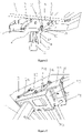
- Fig.1 shows a perspective view of an embodiment of operator's platform of an earth working machine having a protective canopy 1, in which the protective canopy 1 is in the state of an extended operating position.
- Fig.2 shows a perspective view of an embodiment of operator's platform according to Fig.1 , in which the protective canopy 1 is in the state of a retracted transport position.
- the earth working machine is a road milling machine, recycler, stabilizer, or surface miner.
- the earth working machine has an operator's platform 2 and a protective canopy 1, the protective canopy 1 is connected to the operator's platform 2 of the earth working machine through a support, for example a supporting column 11 arranged in the substantially vertical direction of the machine as shown in Figs 1 and 2 .
- the support serves as a part of the base of the protective canopy 1, or is set independently of the base of the protective canopy 1.
- the protective canopy 1 has a canopy body 3, the canopy body 3 has a first position and a second position, wherein the first position is an extended operating position where the canopy body 3 of the protective canopy 1 protrudes from the lateral outer side of machine frame of the earth working machine, and the second position is a retracted transport position where the canopy body 3 of the protective canopy 1 does not protrude outside the footprint of the earth working machine.
- the protective canopy 1 is switchable relative to the operator's platform 2 between the extended operating position and the retracted transport position in the horizontal direction of the earth working machine, such that protecting an operator of the earth working machine from sun or rain.
- the canopy body 3 of the protective canopy 1 protrudes from the lateral outer side of machine frame of the earth working machine when the canopy body 3 is extended to the operating position, and the canopy body 3 of the protective canopy 1 does not protrude outside the footprint of the earth working machine when the canopy body 3 is retracted to the transport position.
- the protective canopy 1 of the earth working machine has no intermediate position but only the transport (very left) and the operating (very right) position, but the positions of the canopy according to the present invention can be better changed with less force and at a lower cost than canopy of construction machine of the prior art.
- the protective canopy 1 further comprises a canopy base 4, which is stationary, a first linkage 5 and a second linkage 6 for connecting the canopy body 3 to the canopy base 4.
- the first linkage 5, the second linkage 6, the canopy body 3 and the canopy base 4 constitutes a four-bar linkage mechanism.
- the switching of the protective canopy 1 according to the present invention between the first operating position and the second transport position is achieved by the four-bar linkage mechanism.
- first linkage 5 being pivotally connected to each of the canopy body 3 and the canopy base 4, respectively
- second linkage 6 being similarly pivotally connected to each of the canopy body 3 and the canopy base 4, respectively
- the pivot axes at the connection points between the first linkage 5 and each of the canopy body 3 and the canopy base 4 and the pivot axis at the connection points between the second linkage 6 and each of the canopy body 3 and the canopy base 4 are parallel to each other, such that the canopy body 3, the canopy base 4, the first linkage 5 and the second linkage 6 together form a four-bar linkage mechanism capable of being manipulated.
- both the first linkage 5 and the second linkage 6 are bent outwardly, respectively, and the protective canopy 1 further comprises one manipulation component integrated with the second linkage 6.
- the manipulation component and the second linkage 6 form a lever structure with a pivoting point where they are connected.
- the manipulation component comprises a connecting section 12 connected to the second linkage 6 and a force-application section 13 connected to the connecting section 12.
- the canopy body 3 is provided with a connection member 9 moving along with the canopy body 3, the first linkage 5 and the second linkage 6 are each pivotally connected to the connection member 9.
- the connection member 9 is integrated with the canopy body 3.
- the first linkage 5 is pivotally connected to the canopy base 4 by a first shaft 18, and the second linkage 6 is pivotally connected to the canopy base 4 by a second shaft 19, the connection member 9 abuts against the first shaft 18 at the first position and abuts against the second shaft 19 at the second position.
- the bottom edge of connection member 9 is provided with one opening 17, each of the first shaft 18 and the second shaft 19 is accommodated in the opening 17 at the first position and the second position of the canopy body 3, respectively.
- the canopy base 4 comprises a base member 10, the first linkage 5 and the second linkage 6 are provided on opposite sides of the base member 10 and the connection member 9, respectively.
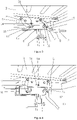
- Fig.3 shows the details of an embodiment of the protective canopy 1 according to the present invention, in which the protective canopy 1 is in the state of an extended operating position.
- Fig.4 shows the details of an embodiment of the protective canopy 1 according to the present invention, in which the protective canopy 1 is in the state of switching from an extended operating position to a retracted transport position.
- Fig.5 shows the details of an embodiment of the protective canopy 1 according to the present invention, in which the protective canopy 1 is in a retracted transport position.
- the canopy body 3 of the protective canopy 1 can be switched from the extended operating position to the retracted transport position, and vice versa.
- the four-bar linkage mechanism capable of being manipulated and formed by the canopy body 3, the canopy base 4, the first linkage 5 and the second linkage 6.
- the first linkage 5 being pivotally connected to each of the canopy body 3 and the canopy base 4, respectively
- the second linkage 6 being similarly pivotally connected to each of the canopy body 3 and the canopy base 4, respectively.
- the connecting section 12 of the manipulation component is in the line of two pivotally connection points of the second linkage 6, and the force-application section 13 is at an angle of about 130° to the connecting section 12. In another embodiment, the angle may also be 100°, 120°, 125°, 135° or 150°.
- the operator can hold the force-application section 13 of the manipulation component by hand, and then apply force to the force-application section 13 to drive the second linkage 6, which in turn drives the first linkage 5 and the canopy body 3 to move, and finally realize the movement of the canopy body 3 from the operating position to the transport position or form the transport position to the operating position.
- first linkages 5, 5a are provided on opposite sides of the base member 10 and the connection member 9
- second linkages 6, 6a are provided on opposite sides of the base member 10 and the connection member 9.
- Figs. 3-5 show the first linkage 5 and the second linkage 6 on one side of the canopy body 3 and the canopy base 4.
- Fig.6 shows the first linkage 5a and the second linkage 6a on the other side of the canopy body 3 and the canopy base 4.
- connection member 9 comprises a first upper side 21 and a second upper side 22 parallel to the first upper side 21, first linkage 5 and second linkage 6 are pivotally connected to the first upper side 21, and the first linkage 5a and the second linkage 6a are pivotally connected to the second upper side 22.
- the base member 10 comprises a first lower side 23, a second lower side 24 parallel to the first lower side and a top plate portion 25 connecting the top of the first lower side and the second lower side, the second ends of one first linkage 5 and one second linkage 6 are pivotally connected to the first lower side 23, and the second ends of the other first linkage 5a and the other second linkage 6a are pivotally connected to the second lower side 24.
- the protective canopy 1 further comprises a locking device 14 for locking the canopy body 3 at its first and second position.
- the locking device 14 is arranged on the canopy body 3 and moves along with the canopy body 3, and two locking holes 7, 7a are arranged on the canopy base 4 for cooperating with the locking device 14 when the canopy body 3 reaches its first and second positions, respectively.
- the locking device 14 is arranged on the canopy base 4, and the locking holes for cooperating with the locking device 14 are arranged on the canopy body 3.
- the locking holes are elongated holes.
- the locking device 14 is a spring-loaded pull in latch, which comprises a housing 26, a pin 27 and a spring element 28.
- the housing 26 can be fixed to the canopy body 3.
- the pin 27 is arranged in the housing 26, and the spring 28 is arranged in the housing 26 for providing load-force to the pin 27.
- the pin 27 is movable between an original position (also referred to as a closing position) and an extracted position (also referred to as an opening position).
- the pin 27 When the pin 27 is pulled, the pin is moving in the housing 26 and the spring element 28 is compressed. In case the pin 27 is pulled and the stop 29 is moved along the receiving slot 30 in the housing to a particular position, the pin 27 can be rotated to make at least one radial stop 29 provided on the pin 27 accommodated in corresponding part, such as the positioning portion (not shown in the figures) provided on the end surface of the housing 26. In this approach, the pin is hold in the extracted position and cannot return back to the original position. If the pin is rotated to make the radial stop 29 leave positioning portion, the force of the spring element 28 makes the pin 27 return to the original position.
- the operator can switch the pin 27 of the locking device 14 from its original position to its extracted position. Now the canopy body 3 is free to be shifted from its first operating position to second transport position or vice versa.
- the pin 27 In the extracted position, the pin 27 is held stationary on the housing 26 against the load of the spring element 28. In case the pin 27 is rotated and its stop 29 is moved to the position of the opening of the receiving slot 30 at the end of the housing, the pin 27 is capable of being returned to its original position by the action of the spring element 28.
- the pin 27 of the locking device When the canopy body reaches its first position and second position, the pin 27 of the locking device is in its original position and is inserting into the corresponding locking hole, so that the canopy body is locked in its first position and second position.
- two switch elements 15, 16 are provided on the canopy base, and arranged near to the movement trajectory of the pin when the canopy body moves from the first position to the second position and vice versa. During the movement of the canopy body 3 from the first position to the second position and from the second position to the first position, the two switch elements 15, 16 enable the pin 27 to be released from its extracted position, respectively.
- the pin 27 has a wing 31 which is radially extended from the end of the pin, and when the wing contacts with the switch elements, it triggers the pin to rotate so that the pin is released from the extracted position.
- the pin 27 is capable of being toggled to rotate by the engagement of the wing 31 and the corresponding switch element 15, 16, so that the pin 27 is capable of being released from its extracted position when the canopy reaches its final position.
- the spring element 28 cannot push out the pin 27 instantly before the canopy reaches its final position, i.e., there is no corresponding hole in the intermediate position where the pin 27 can go in. Therefore, only when the final position is reached, the spring 28 can push the pin 27 out and into the corresponding locking hole and close the latch, i.e., fix the canopy body 3 in its final position.
- the switch elements 15, 16 are a L-shaped flags, wherein at least a vertical portion of the L-shaped flag will contact the wing 31 of the pin 27 of the locking device 14 during the movement of the canopy body 3, such that the pin 27 is driven to rotate and then capable of being released from its extracted position when the canopy body 3 reaches its final position.
Landscapes
- Engineering & Computer Science (AREA)
- Architecture (AREA)
- Civil Engineering (AREA)
- Structural Engineering (AREA)
- Mining & Mineral Resources (AREA)
- Electromagnetism (AREA)
- Physics & Mathematics (AREA)
- General Engineering & Computer Science (AREA)
- Mechanical Engineering (AREA)
- Life Sciences & Earth Sciences (AREA)
- Geology (AREA)
- Geochemistry & Mineralogy (AREA)
- General Life Sciences & Earth Sciences (AREA)
- Body Structure For Vehicles (AREA)
Abstract
Description
- The invention relates to a protective canopy having a canopy body, which is switchable between a first position and a second position, a canopy base, a first linkage and a second linkage for connecting the canopy body to the canopy base, each of the first linkage and the second linkage is pivotally connected to both the canopy body and the canopy base, respectively, and pivot axes formed at the pivoting connection positions between each of the first and second linkage and each of the canopy body and the canopy base are parallel to each other, such that the canopy body is switchable relative to the canopy base between the first position and the second position by manipulating the first and/or second linkages and/or the canopy body. The invention further relates to an earth working machine, which including an operator's platform and the protective canopy which is switchable between a first position and a second position, the protective canopy is arranged corresponding to the operator's platform for protecting the operator. The invention further relates to a method for controlling position of the protective canopy, including steps of extending and retracting the canopy body of the protective canopy relative to the operator's platform of the earth working machine.
- Regarding a construction machine, such as an earth working machine, a protective canopy is provided above the operator's platform to protect the operator from sun or rain. In the state of the art, the change of position of the protective canopy arranged on the construction machine is implemented by means of a bearing mechanism, such as sliding bearings and rolling contact bearing also referred to as ball screw. However, the position change structure implemented by a sliding bearing makes the protective canopy get stuck very frequently and easily during the position changing, and it requires considerable force to make the protective canopy move. Although the position change structure implemented by a rolling contact bearing requires les force, the cost of the rolling contact bearing is very high.
- Therefore, there is a great need for a protective canopy position change structure that can easily cause the protective canopy to change position with less force and at a lower cost.
- The object of the invention is therefore to refine the protective canopy recited previously in such a way that the position of the canopy body can be better changed with less force and at a lower cost than canopy of construction machine of the existing art. In addition, it is an object of the invention to provide an earth working machine having such protective canopy, making the operator of the machine be better protected.
- According to the present invention the objects are achieved following features of the protective canopy.
- The protective canopy comprises a canopy body, which is switchable between a first position and a second position, a canopy base, which is stationary, a first linkage and a second linkage for connecting the canopy body to the canopy base, each of the first linkage and the second linkage is pivotally connected to both the canopy body and the canopy base, respectively, and pivot axes formed at the pivoting connection positions between each of the first and second linkage and each of the canopy body and the canopy base are parallel to each other, such that the canopy body is switchable relative to the canopy base between the first position and the second position by manipulating the first and/or second linkages and/or the canopy body.
- According to the protective canopy of the present invention, the first linkage, the second linkage, the canopy body and the canopy base can constitute a four-bar linkage mechanism, which makes the position of the canopy body can be better changed with less force and at a lower cost than canopy of construction machine of the existing art.
- Unlike the protective canopy recited previously in the background of the present invention, the protective canopy according to the present invention has a first position and a second position, and the switching of the protective canopy according to the present invention between the first operating position and the second transport position is achieved by a four-bar linkage mechanism formed by the canopy body of the protective canopy, the canopy base, the first linkage and the second linkage together. Specifically, the canopy body of the protective canopy and the canopy base are connected by means of the first linkage and the second linkage, wherein the first linkage being pivotally connected to each of the canopy body and the canopy base, respectively, and the second linkage being similarly pivotally connected to each of the canopy body and the canopy base, respectively, and the pivot axes at the connection points between the first linkage and each of the canopy body and the canopy base and the pivot axes at the connection points between the second linkage and each of the canopy body and the canopy base parallel to each other, such that the canopy body, the canopy base, the first linkage and the second linkage together form a four-bar linkage mechanism capable of being manipulated. By manipulating at least one of the canopy body, the first linkage and the second linkage, the canopy can be switched with respect to the canopy base between the first position and the second position.
- This involves the advantage that, compared to the existing art, the protective canopy of the present invention has no intermediate position but only the transport (very left) and the operating (very right) position, but the positions of the canopy according to the present invention can be better changed with less force and at a lower cost than canopy of construction machine of the existing art.
- According to the protective canopy of the present invention, the protective canopy can further comprise at least one manipulation component, which can be capable of driving at least one of the first linkage, the second linkage and the canopy body, the canopy body is switchable relative to the canopy base between the first position and the second position by manipulating the manipulation component.
- According to the protective canopy of the present invention, the at least one manipulation component can be attached to the first linkage and/or the second linkage, and the at least one manipulation component and corresponding linkage can form a lever structure with a pivoting point where they are connected. This involves the advantage of providing an effortless and cost-effective way of switching the canopy body between its first position and its second position. In a preferred embodiment, the manipulation component is attached to one of the first and second linkage, and the manipulation component together with the corresponding linkage forms a lever structure, wherein a pivoting connection point formed by the pivoting connection between the corresponding linkage and one of the canopy body and the canopy base acts as a fulcrum of the lever structure. Alternatively, the at least one manipulation component is attached to the first and second linkage, respectively, and the manipulation component and the linkage to which the manipulation component form a lever structure.
- According to the protective canopy of the present invention, the at least one manipulation component can comprise a connecting section connected to the first and/or the second linkage and a force-application section connected to the connecting section, the connecting section of the at least one manipulation component can be in the line of two pivotally connection points of the linkage to which the at least one manipulation component can be attached, and the force-application section can be at an angle of 100-150° to the connecting section. Here this will be illustrated based on the case where the manipulation component is attached to the second linkage. Specifically, the second linkage has a first pivoting connection point pivotally connected to the canopy body and a second pivoting connection point pivotally connected to the canopy base, the line between the first pivoting connection point and the second pivoting connection point being at an angle with the force-application section of the manipulation component, which ranges from 100-150°. In a preferred embodiment, the force-application section is at an angle (α) of 120-130° to the connecting section. In some more preferred embodiments, the angle is 120°, 125°, or 130°. This involves the advantage that in this range of angle, a smaller force is required to drive the corresponding linkage to which the manipulation component is attached.
- According to the protective canopy of the present invention, the at least one manipulation component can be integrated with the first and/or second linkage. In a preferred embodiment, the manipulation component is integrated with one of the first and second linkage. This involves the advantage of enabling the manipulation component to be manufactured, installed, and used integrated with the corresponding linkage to which the manipulation component is attached, which not only provides better structural strength, but also reduces the number of parts required, ease of installation and use, as well as cost reduction.
- Alternatively, according to the protective canopy of the present invention, the at least one manipulation component can be hydraulic, electric, or pneumatic driving devices, which can act directly on at least one of the first linkage, the second linkage and the canopy body, or drives at least one of the first linkage, the second linkage and the canopy body through an indirect driving mechanism. In another alternatively embodiment, the manipulation component is connected to the first and/or second linkage by an additional pivoting connection, for example the manipulation component forms a new pivoting-related structure with the first and/or second linkage, which allows the first and/or second linkage to be driven for a movement.
- According to the protective canopy of the present invention, both the first linkage and the second linkage can be bent outwardly, respectively. This involves the advantage of facilitating the movement of the canopy between the first position and the second position and facilitating the transmission of the driving force introduced by the manipulation component between the linkages and the canopy body.
- According to the protective canopy of the present invention, the canopy body can abut against the canopy base at both the first position and the second position of the canopy body. This involves the advantage that the canopy body can be stopped in its desired positions by abutting against the canopy base, without the need for additional stopping elements.
- According to the protective canopy of the present invention, the canopy body can be provided with a connection member moving along with the canopy body, the first linkage and the second linkage can each be pivotally connected to the connection member. In a preferred embodiment, the connection member is integrated with the canopy body. Alternatively, the attachment member is attached to the canopy body by existing known mechanical connecting means, such as welding or bolting.
- According to the protective canopy of the present invention, the connection member of the canopy body can abut against the canopy base at both the first position and the second position of the canopy body.
- Alternatively, the first linkage can be pivotally connected to the canopy base by a first shaft, and the second linkage can be pivotally connected to the canopy base by a second shaft, the connection member can abut against the first shaft at the first position and can abut against the second shaft at the second position. In a preferred embodiment, the bottom edge of connection member can be provided with one opening, each of the first shaft and the second shaft can be accommodated in the opening at the first position and the second position of the canopy body, respectively.
- According to the protective canopy of the present invention, a pair of the first linkage and a pair of the second linkage can be provided on two opposite sides of the canopy base and the connection member, respectively.
- According to the protective canopy of the present invention, the protective canopy can further comprise a locking device for locking the canopy body at its first and second position. In a preferred embodiment, the locking device can be arranged on the canopy body and can move along with the canopy body, and two locking holes can be arranged on the canopy base for cooperating with the locking device when the canopy body reaches its first and second positions, respectively. Alternatively, the locking device is arranged on the canopy base, and the locking holes for cooperating with the locking device are arranged on the canopy body.
- According to the protective canopy of the present invention, the locking device can be a spring-loaded pull in latch, which can comprise a housing, a pin and a spring element, the pin is moveable between an original position and an extracted position, the spring element can not be compressed when the pin is in the original position, while it can be compressed when the pin is in the extracted position. Specifically, the housing is arranged on the canopy body, the pin is arranged in the housing, and the spring is arranged in the housing for providing load-force to the pin, and the pin has an original position (also referred to as a closing position) and an extracted position (also referred to as an opening position) where the pin is held stationary on the housing against the load of the spring element, and the pin is capable of being returned to its original position by the action of the spring element when the pin is released from its extracted position.
- When the canopy body reaches its first position and second position, the pin of the locking device is in its original position and is inserting into the corresponding locking hole, so that the canopy body is locked in its first position and second position. In a preferred embodiment, at least one radial stop can be provided on the pin, and the pin can be kept at the extracted position by rotating the pin to make the stop engaged with corresponding part in the housing. The pin can be pulled outwards in the direction of its longitudinal axis and then be rotated around the longitudinal axis, so that the stop of the pin fits into a corresponding part in the housing, such as a positioning portion provided at the end of the housing or inside the housing, so that the pin is positioned in its extracted position that allows the canopy body to be unlocked. Therefore, before shifting the canopy from its first position to second position and from its second position to first position, the operator can switch the pin of the locking device from its original position to its extracted position. Now the canopy is free to be shifted from its first operating position to second transport position or vice versa.
- According to the protective canopy of the present invention, two switch elements can be provided on the canopy base and arranged near to the movement trajectory of the pin when the canopy body moves from the first position to the second position and vice versa. During the movement of the canopy body from the first position to the second position and from the second position to the first position, the two switch elements enable the pin to be released from its extracted position, respectively.
- According to the protective canopy of the present invention, the pin has a wing which can be radially extended from the end of the pin, and when the wing can contact with the switch elements, it can trigger the pin to rotate so that the pin can be released from the extracted portion. During the movement of the canopy body from the first position to the second position and from the second position to the first position, the pin is capable of being toggled to rotate by the engagement between the wing and the corresponding switch element, so that the pin is capable of being released from its extracted position when the canopy reaches its final position.
- As soon as the canopy body leaves it final position, the wing of the pin of the locking device has to pass the two switch elements, respectively. The corresponding switch element will engage the wing of the pin of the locking device and will enable the pin to rotate, resulting in the pin being able to be released from its extracted position when the canopy reaches its final position, i.e., the first operating position and the second transport position. According to the protective canopy of the present invention, the spring element cannot push out the pin instantly before the canopy reaches its final position, i.e., there is no corresponding hole in the intermediate position where the pin can go in. Therefore, only when the final position is reached, the spring can push the pin out and into the corresponding locking hole and close the latch, i.e., fix the canopy in its final position.
- In a preferred embodiment, the switch elements are a L-shaped flags, wherein at least a vertical portion of the L-shaped flag will contact the wing of the pin of the locking device during the movement of the canopy body, such that the pin is driven to rotate and then capable of being released from its extracted position when the canopy body reaches its final position.
- According to the protective canopy of the present invention, the first position can be an extended operating position of the canopy body, and the second position can be a retracted transport position of the canopy body relative to the extended operating position.
- The present invention further provides an earth working machine, the earth working machine can comprise operator's platform and the protective canopy according to the above mentioned, the protective canopy can be arranged corresponding to the operator's platform for protecting the operator.
- According to the earth working machine of the present invention, the canopy body of the protective canopy can be switchable between the first position and the second position with respect to the operator's platform in the horizontal direction of the earth working machine.
- According to the earth working machine of the present invention, the first position can be an extended operating position where the canopy body of the protective canopy can protrude from the lateral outer side of machine frame of the earth working machine, and the second position can be a retracted transport position where the canopy body of the protective canopy does not protrude outside the footprint of the earth working machine. That is, the canopy body of the protective canopy protrudes from the lateral outer side of machine frame of the earth working machine when the canopy body is extended to the operating position, and the canopy body of the protective canopy does not protrude outside the footprint of the earth working machine when the canopy body is retracted to the transport position. This involves the advantage that the protective canopy of the earth working machine according to the present invention is shiftable from transport position where it does not protrude outside the footprint of the machine to the operating position where it protrude from the lateral outer side (also referred to so called zero-extension side, which in a preferred embodiment is the right hand side of the machine) of machine frame of the earth working machine to better cover the operator from sun and rain. The protective canopy of the earth working machine has no intermediate position but only the transport (very left) and the operating (very right) position. This involves the advantage of providing an effortless and cost-effective way of switching the canopy body between its first position and its second position.
- According to the earth working machine of the present invention, the earth working machine can be a road milling machine, recycler, stabilizer or surface miner.
- The invention can further relate to a method for changing position of a protective canopy of earth working machine, the above-mentioned protective canopy can be arranged corresponding to the operator's platform for protecting the operator, the method can comprise steps of extending and retracting the canopy body of the protective canopy relative to the operator's platform of the earth working.
- Embodiments of the present invention are explained in more detail below with reference to the Figures,
- in which:
-
Fig.1 shows a perspective view of an embodiment of operator's platform of an earth working machine having a protective canopy, in which the protective canopy is in the state of an extended operating position, -
Fig.2 shows a perspective view of an embodiment of operator's platform according toFig.1 , in which the protective canopy is in the state of a retracted transport position, -
Fig.3 shows the details of an embodiment of the protective canopy according to the present invention, in which the protective canopy is in the state of an extended operating position, -
Fig.4 shows the details of an embodiment of the protective canopy according to the present invention, in which the protective canopy is in the state of switching from an extended operating position to a retracted transport position, -
Fig.5 shows the details of an embodiment of the protective canopy according to the present invention, in which the protective canopy is in the state of a retracted transport position, -
Fig.6 shows the details of protective canopy viewed from the bottom of the base, in which additional first and second linkages located on the opposite side of protective base with respect to the manipulation component are shown, -
Fig.7 shows the details of the locking device in a cross-section view, wherein the pin of the locking device is in its original position, -
Fig.8 shows the details of the locking device in a cross-section view, wherein the pin of the locking device is in its extracted position. -
Fig.1 shows a perspective view of an embodiment of operator's platform of an earth working machine having a protective canopy 1, in which the protective canopy 1 is in the state of an extended operating position.Fig.2 shows a perspective view of an embodiment of operator's platform according toFig.1 , in which the protective canopy 1 is in the state of a retracted transport position. In the present embodiment, the earth working machine is a road milling machine, recycler, stabilizer, or surface miner. - As shown in
figures 1-2 , the earth working machine has an operator'splatform 2 and a protective canopy 1, the protective canopy 1 is connected to the operator'splatform 2 of the earth working machine through a support, for example a supportingcolumn 11 arranged in the substantially vertical direction of the machine as shown inFigs 1 and2 . The support serves as a part of the base of the protective canopy 1, or is set independently of the base of the protective canopy 1. - As shown in
figures 1-2 , the protective canopy 1 has acanopy body 3, thecanopy body 3 has a first position and a second position, wherein the first position is an extended operating position where thecanopy body 3 of the protective canopy 1 protrudes from the lateral outer side of machine frame of the earth working machine, and the second position is a retracted transport position where thecanopy body 3 of the protective canopy 1 does not protrude outside the footprint of the earth working machine. The protective canopy 1 is switchable relative to the operator'splatform 2 between the extended operating position and the retracted transport position in the horizontal direction of the earth working machine, such that protecting an operator of the earth working machine from sun or rain. In the present embodiment, thecanopy body 3 of the protective canopy 1 protrudes from the lateral outer side of machine frame of the earth working machine when thecanopy body 3 is extended to the operating position, and thecanopy body 3 of the protective canopy 1 does not protrude outside the footprint of the earth working machine when thecanopy body 3 is retracted to the transport position. The protective canopy 1 of the earth working machine has no intermediate position but only the transport (very left) and the operating (very right) position, but the positions of the canopy according to the present invention can be better changed with less force and at a lower cost than canopy of construction machine of the prior art. - As shown in the
figures 1-2 , the protective canopy 1 further comprises acanopy base 4, which is stationary, afirst linkage 5 and asecond linkage 6 for connecting thecanopy body 3 to thecanopy base 4. In the present embodiment, thefirst linkage 5, thesecond linkage 6, thecanopy body 3 and thecanopy base 4 constitutes a four-bar linkage mechanism. The switching of the protective canopy 1 according to the present invention between the first operating position and the second transport position is achieved by the four-bar linkage mechanism. Specifically, thefirst linkage 5 being pivotally connected to each of thecanopy body 3 and thecanopy base 4, respectively, and thesecond linkage 6 being similarly pivotally connected to each of thecanopy body 3 and thecanopy base 4, respectively, and the pivot axes at the connection points between thefirst linkage 5 and each of thecanopy body 3 and thecanopy base 4 and the pivot axis at the connection points between thesecond linkage 6 and each of thecanopy body 3 and thecanopy base 4 are parallel to each other, such that thecanopy body 3, thecanopy base 4, thefirst linkage 5 and thesecond linkage 6 together form a four-bar linkage mechanism capable of being manipulated. - As shown in the
figures 1-2 , both thefirst linkage 5 and thesecond linkage 6 are bent outwardly, respectively, and the protective canopy 1 further comprises one manipulation component integrated with thesecond linkage 6. The manipulation component and thesecond linkage 6 form a lever structure with a pivoting point where they are connected. Specifically, the manipulation component comprises a connectingsection 12 connected to thesecond linkage 6 and a force-application section 13 connected to the connectingsection 12. - As shown in the
figures 1-2 , thecanopy body 3 is provided with aconnection member 9 moving along with thecanopy body 3, thefirst linkage 5 and thesecond linkage 6 are each pivotally connected to theconnection member 9. In the present embodiment, theconnection member 9 is integrated with thecanopy body 3. Thefirst linkage 5 is pivotally connected to thecanopy base 4 by afirst shaft 18, and thesecond linkage 6 is pivotally connected to thecanopy base 4 by asecond shaft 19, theconnection member 9 abuts against thefirst shaft 18 at the first position and abuts against thesecond shaft 19 at the second position. In the present embodiment, the bottom edge ofconnection member 9 is provided with oneopening 17, each of thefirst shaft 18 and thesecond shaft 19 is accommodated in theopening 17 at the first position and the second position of thecanopy body 3, respectively. Moreover, in the present embodiment, thecanopy base 4 comprises abase member 10, thefirst linkage 5 and thesecond linkage 6 are provided on opposite sides of thebase member 10 and theconnection member 9, respectively. -
Fig.3 shows the details of an embodiment of the protective canopy 1 according to the present invention, in which the protective canopy 1 is in the state of an extended operating position.Fig.4 shows the details of an embodiment of the protective canopy 1 according to the present invention, in which the protective canopy 1 is in the state of switching from an extended operating position to a retracted transport position.Fig.5 shows the details of an embodiment of the protective canopy 1 according to the present invention, in which the protective canopy 1 is in a retracted transport position. As shown inFigs 3-5 , thecanopy body 3 of the protective canopy 1 can be switched from the extended operating position to the retracted transport position, and vice versa. This is achieved by the four-bar linkage mechanism capable of being manipulated and formed by thecanopy body 3, thecanopy base 4, thefirst linkage 5 and thesecond linkage 6. Thefirst linkage 5 being pivotally connected to each of thecanopy body 3 and thecanopy base 4, respectively, and thesecond linkage 6 being similarly pivotally connected to each of thecanopy body 3 and thecanopy base 4, respectively. By manipulating at least one of thecanopy body 3, thefirst linkage 5 and thesecond linkage 6, the canopy can be switched with respect to thecanopy base 4 between the extended operating position and the retracted transport position. - As shown in
figure 3 , the connectingsection 12 of the manipulation component is in the line of two pivotally connection points of thesecond linkage 6, and the force-application section 13 is at an angle of about 130° to the connectingsection 12. In another embodiment, the angle may also be 100°, 120°, 125°, 135° or 150°. The operator can hold the force-application section 13 of the manipulation component by hand, and then apply force to the force-application section 13 to drive thesecond linkage 6, which in turn drives thefirst linkage 5 and thecanopy body 3 to move, and finally realize the movement of thecanopy body 3 from the operating position to the transport position or form the transport position to the operating position. - As shown in the
figures 3-6 , twofirst linkages base member 10 and theconnection member 9, and twosecond linkages 6, 6a are provided on opposite sides of thebase member 10 and theconnection member 9.Figs. 3-5 show thefirst linkage 5 and thesecond linkage 6 on one side of thecanopy body 3 and thecanopy base 4.Fig.6 shows thefirst linkage 5a and the second linkage 6a on the other side of thecanopy body 3 and thecanopy base 4. - As shown in
Figs. 1-6 , theconnection member 9 comprises a firstupper side 21 and a secondupper side 22 parallel to the firstupper side 21,first linkage 5 andsecond linkage 6 are pivotally connected to the firstupper side 21, and thefirst linkage 5a and the second linkage 6a are pivotally connected to the secondupper side 22. Thebase member 10 comprises a firstlower side 23, a secondlower side 24 parallel to the first lower side and atop plate portion 25 connecting the top of the first lower side and the second lower side, the second ends of onefirst linkage 5 and onesecond linkage 6 are pivotally connected to the firstlower side 23, and the second ends of the otherfirst linkage 5a and the other second linkage 6a are pivotally connected to the secondlower side 24. - Differing from the embodiment as shown in
figures 1-2 , in the present embodiment as shown in thefigures 3-5 , the protective canopy 1 further comprises alocking device 14 for locking thecanopy body 3 at its first and second position. In a preferred embodiment, the lockingdevice 14 is arranged on thecanopy body 3 and moves along with thecanopy body 3, and two lockingholes canopy base 4 for cooperating with the lockingdevice 14 when thecanopy body 3 reaches its first and second positions, respectively. Alternatively, the lockingdevice 14 is arranged on thecanopy base 4, and the locking holes for cooperating with the lockingdevice 14 are arranged on thecanopy body 3. Preferably, the locking holes are elongated holes. -
Fig.7 shows the details of the locking device in a cross-section view, wherein the pin of the locking device is in its original position.Fig.8 shows the details of the locking device in a cross-section view, wherein the pin of the locking device is in its extracted position. As shown infigures 7-8 , the lockingdevice 14 is a spring-loaded pull in latch, which comprises ahousing 26, apin 27 and aspring element 28. Thehousing 26 can be fixed to thecanopy body 3. Thepin 27 is arranged in thehousing 26, and thespring 28 is arranged in thehousing 26 for providing load-force to thepin 27. Thepin 27 is movable between an original position (also referred to as a closing position) and an extracted position (also referred to as an opening position). When thepin 27 is pulled, the pin is moving in thehousing 26 and thespring element 28 is compressed. In case thepin 27 is pulled and thestop 29 is moved along the receivingslot 30 in the housing to a particular position, thepin 27 can be rotated to make at least oneradial stop 29 provided on thepin 27 accommodated in corresponding part, such as the positioning portion (not shown in the figures) provided on the end surface of thehousing 26. In this approach, the pin is hold in the extracted position and cannot return back to the original position. If the pin is rotated to make theradial stop 29 leave positioning portion, the force of thespring element 28 makes thepin 27 return to the original position. That is, before shifting the canopy from its first position to second position and from its second position to first position, the operator can switch thepin 27 of thelocking device 14 from its original position to its extracted position. Now thecanopy body 3 is free to be shifted from its first operating position to second transport position or vice versa. - In the extracted position, the
pin 27 is held stationary on thehousing 26 against the load of thespring element 28. In case thepin 27 is rotated and itsstop 29 is moved to the position of the opening of the receivingslot 30 at the end of the housing, thepin 27 is capable of being returned to its original position by the action of thespring element 28. When the canopy body reaches its first position and second position, thepin 27 of the locking device is in its original position and is inserting into the corresponding locking hole, so that the canopy body is locked in its first position and second position. - As shown in the
figures 3-5 , twoswitch elements canopy body 3 from the first position to the second position and from the second position to the first position, the twoswitch elements pin 27 to be released from its extracted position, respectively. - As shown in
figures 3-5 and7, thepin 27 has awing 31 which is radially extended from the end of the pin, and when the wing contacts with the switch elements, it triggers the pin to rotate so that the pin is released from the extracted position. During the movement of thecanopy body 3 from the first position to the second position and from the second position to the first position, thepin 27 is capable of being toggled to rotate by the engagement of thewing 31 and thecorresponding switch element pin 27 is capable of being released from its extracted position when the canopy reaches its final position. According to the protective canopy of the present invention, thespring element 28 cannot push out thepin 27 instantly before the canopy reaches its final position, i.e., there is no corresponding hole in the intermediate position where thepin 27 can go in. Therefore, only when the final position is reached, thespring 28 can push thepin 27 out and into the corresponding locking hole and close the latch, i.e., fix thecanopy body 3 in its final position. - As shown in the
figures 3-5 , theswitch elements wing 31 of thepin 27 of thelocking device 14 during the movement of thecanopy body 3, such that thepin 27 is driven to rotate and then capable of being released from its extracted position when thecanopy body 3 reaches its final position.
Claims (15)
- A protective canopy (1), characterized in that
the protective canopy (1) comprises:a canopy body (3), which is switchable between a first position and a second position,a canopy base (4), anda first linkage (5) and a second linkage (6) for connecting the canopy body (3) to the canopy base (4),each of the first linkage (5) and the second linkage (6) is pivotally connected to both the canopy body (3) and the canopy base (4) respectively, and pivot axes formed at the pivoting connection positions between each of the first and second linkage and each of the canopy body (3) and the canopy base (4) are parallel to each other, such that the canopy body (3) is switchable relative to the canopy base (4) between the first position and the second position by manipulating the first and/or second linkages and/or the canopy body (3). - The protective canopy (1) according to claim 1, characterized in that the first linkage (5), the second linkage (6), the canopy body (3) and the canopy base (4) constitute a four-bar linkage mechanism.
- The protective canopy (1) according to claim 1 or 2, characterized in that the protective canopy (1) further comprises at least one manipulation component (8), which is capable of driving at least one of the first linkage (5), the second linkage (6) and the canopy body (3), the canopy body (3) is switchable relative to the canopy base (4) between the first position and the second position by manipulating the manipulation component (8).
- The protective canopy (1) according to claim 3, characterized in that the at least one manipulation component (8) is attached to the first linkage (5) and/or the second linkage (6), and the at least one manipulation component (8) and corresponding linkage form a lever structure with a pivoting point where they are connected and/or
the at least one manipulation component (8) is hydraulic, electric, or pneumatic driving devices, which acts directly on at least one of the first linkage (5), the second linkage (6) and the canopy body (3), or drives at least one of the first linkage (5), the second linkage (6) and the canopy body (3) through an indirect driving mechanism. - The protective canopy (1) according to claim 4, characterized in thatthe at least one manipulation component (8) comprises a connecting section (12) connected to the first and/or the second linkage (6) and a force-application section (13) connected to the connecting section (12), the connecting section (12) of the at least one manipulation component (8) is in the line (L) of two pivotally connection points of the linkage to which the at least one manipulation component (8) is attached, and the force-application section (13) is at an angle (α) of 100-150°, preferably of 120-130° to the connecting section (12)and/or the at least one manipulation component (8) is integrated with the first and/or second linkage.
- The protective canopy (1) according to any one of claims 1-5, characterized in thatboth the first linkage (5) and the second linkage (6) are bent outwardly and/orthe canopy body (3) abuts against the canopy base (4) at both the first position and the second position of the canopy body (3) and/orthe canopy body (3) is provided with a connection member (9) moving along with the canopy body (3), the first linkage (5) and the second linkage (6) are each pivotally connected to the connection member (9), wherein preferably the connection member (9) abuts against the canopy base (4) at both the first position and the second position of the canopy body (3).
- The protective canopy (1) according to claim 6, characterized in that the first linkage (5) is pivotally connected to the canopy base (4) by a first shaft (18), and the second linkage (6) is pivotally connected to the canopy base (4) by a second shaft (19), the connection member (9) abuts against the first shaft (18) at the first position and abuts against the second shaft (19) at the second position.
- The protection canopy according to claim 7, characterized in that
the bottom edge of connection member (9) is provided with one opening (17), the first shaft (18) or the second shaft (19) is accommodated in the opening (17) at the first position and the second position of the canopy body, respectively. - The protective canopy (1) according to claim 6-8, characterized in that
a pair of the first linkage (5) and a pair of the second linkage (6) are provided on two opposite sides of the canopy base (4) and the connection member (9), respectively. - The protective canopy (1) according to any one of claims 1-9, characterized in that the protective canopy (1) further comprises a locking device (14) for locking the canopy body (3) at its first and second positions,
wherein preferably- the locking device (14) is arranged on the canopy body (3) and moves along with the canopy body (3)- and/or two locking holes (7, 7a) are provided on the canopy base (4) for cooperating with the locking device (14). - The protective canopy (1) according to claim 10, characterized in thatthe locking device (14) comprises a housing (26), a pin (27) and a spring element (28), the pin (27) is moveable between an original position and an extracted position, the spring element (28) is not compressed when the pin (27) is in the original position, while compressed when the pin (27) is in the extracted position wherein preferably- the pin (27) has a stop (29) provided thereon, and the pin (27) can be kept at the extracted position by rotating the pin (27) to make the stop (29) engaged with corresponding part in the housingand/or two switch elements (15, 16) are provided on the canopy base (4) and arranged near to the movement trajectory of the pin (27) when the canopy body (3) moves from the first position to the second position and vice versa.
- The protective canopy (1) according to any one of claims 1-11, characterized in that
the first position is an extended operating position of the canopy body (3), and the second position is a retracted transport position of the canopy body (3) relative to the extended operating position. - A earth working machine, characterized in that
the earth working machine comprises operator's platform and the protective canopy (1) according to any one of claims 1-23, the protective canopy (1) is arranged corresponding to the operator's platform for protecting the operator, wherein preferably the canopy body (3) of the protective canopy (1) is switchable between the first position and the second position with respect to the operator's platform in the horizontal direction of the earth working machine. - The earth working machine according to claim 13, characterized in that the earth working machine is a road milling machine, recycler, stabilizer or surface miner.
- A method for changing position of a protective canopy (1) of earth working machine, characterized in thatthe protective canopy (1) is the protective canopy (1) according to any one of claims 1-14, the protective canopy (1) is arranged corresponding to the operator's platform for protecting the operator,the method comprises steps of extending and retracting the canopy body (3) of the protective canopy (1) relative to the operator's platform of the earth working.
Applications Claiming Priority (1)
| Application Number | Priority Date | Filing Date | Title |
|---|---|---|---|
| CN202110666833.1A CN115478712B (en) | 2021-06-16 | 2021-06-16 | Protective roof, floor processing machine and method for changing the position of a protective roof |
Publications (1)
| Publication Number | Publication Date |
|---|---|
| EP4108839A1 true EP4108839A1 (en) | 2022-12-28 |
Family
ID=82067416
Family Applications (1)
| Application Number | Title | Priority Date | Filing Date |
|---|---|---|---|
| EP22179183.3A Pending EP4108839A1 (en) | 2021-06-16 | 2022-06-15 | Protective canopy, earth working machine and method for changing position of the protective canopy |
Country Status (3)
| Country | Link |
|---|---|
| US (1) | US12054911B2 (en) |
| EP (1) | EP4108839A1 (en) |
| CN (1) | CN115478712B (en) |
Citations (3)
| Publication number | Priority date | Publication date | Assignee | Title |
|---|---|---|---|---|
| US3713688A (en) * | 1970-10-27 | 1973-01-30 | Hyster Co | Multiple position overhead guard |
| US3917310A (en) * | 1973-11-24 | 1975-11-04 | Caterpillar Tractor Co | Collapsible canopy assembly |
| US20140035344A1 (en) * | 2012-07-31 | 2014-02-06 | Caterpillar Paving Products Inc. | Folding Canopy for Cold Planer Machine |
Family Cites Families (7)
| Publication number | Priority date | Publication date | Assignee | Title |
|---|---|---|---|---|
| US7152903B2 (en) * | 2004-01-30 | 2006-12-26 | Westendorf Manufacturing Co., Inc. | Tractor, a canopy assembly, and a method for attaching a canopy assembly to a tractor |
| US7775229B2 (en) * | 2008-08-29 | 2010-08-17 | Bravo Sports | Canopy with one or more side awnings |
| GB201122102D0 (en) * | 2011-12-22 | 2012-02-01 | Dmg Global Ltd | A canopy |
| US10597897B2 (en) * | 2016-07-26 | 2020-03-24 | Shengyong Yang | Collapsible canopy with a self locking central lock |
| DE102017221053A1 (en) * | 2017-11-24 | 2019-05-29 | Wirtgen Gmbh | Soil cultivation machine with together with a protective roof raised and lowered disc assembly |
| CN109972480A (en) * | 2019-04-29 | 2019-07-05 | 陈建军 | A kind of engineering driving vehicle and paver |
| JP7403438B2 (en) * | 2020-12-24 | 2023-12-22 | 株式会社クボタ | work vehicle |
-
2021
- 2021-06-16 CN CN202110666833.1A patent/CN115478712B/en active Active
-
2022
- 2022-06-07 US US17/834,655 patent/US12054911B2/en active Active
- 2022-06-15 EP EP22179183.3A patent/EP4108839A1/en active Pending
Patent Citations (3)
| Publication number | Priority date | Publication date | Assignee | Title |
|---|---|---|---|---|
| US3713688A (en) * | 1970-10-27 | 1973-01-30 | Hyster Co | Multiple position overhead guard |
| US3917310A (en) * | 1973-11-24 | 1975-11-04 | Caterpillar Tractor Co | Collapsible canopy assembly |
| US20140035344A1 (en) * | 2012-07-31 | 2014-02-06 | Caterpillar Paving Products Inc. | Folding Canopy for Cold Planer Machine |
Also Published As
| Publication number | Publication date |
|---|---|
| CN115478712B (en) | 2025-06-24 |
| US20220403618A1 (en) | 2022-12-22 |
| US12054911B2 (en) | 2024-08-06 |
| CN115478712A (en) | 2022-12-16 |
Similar Documents
| Publication | Publication Date | Title |
|---|---|---|
| US4623160A (en) | Extensible step assembly for vehicles | |
| US10676033B1 (en) | Deployable step assembly for vehicles | |
| CN101676491B (en) | Protective roof structure for the driver stand of a construction machine | |
| US11560118B2 (en) | Drive assembly for driving a vehicle flap | |
| EP1276624B1 (en) | Rod on rail power liftgate drive mechanism | |
| US12214742B2 (en) | Drive device having a coupling device for a vehicle flap | |
| EP4108839A1 (en) | Protective canopy, earth working machine and method for changing position of the protective canopy | |
| KR20080000757A (en) | Shackle assembly | |
| US7100962B2 (en) | Convertible roof bow control mechanism | |
| CN2629192Y (en) | Operating device for loading switch | |
| CN116696170B (en) | A car door hinge structure that integrates scissor-opening and swing-opening mechanisms. | |
| CN111933476A (en) | Interlocking structure used between circuit breaker operating mechanism and three-station operating mechanism | |
| EP1818493B1 (en) | A mechanism for opening a closure | |
| CN107237560B (en) | Auxiliary lock device for auxiliary lock door | |
| US20220048369A1 (en) | Top compartment lid assembly comprising a link assembly and a locking assembly | |
| EP4001573A1 (en) | Plug door device | |
| CN102306909B (en) | Valve self-locking mechanism of metal enclosed switch equipment | |
| US20170191240A1 (en) | Work Tool Coupler Engagement System | |
| CN109653620B (en) | Door lock structure of working bucket, working bucket and fire engine | |
| CN117366040B (en) | Interlocking device and mining equipment operation valve group applying same | |
| EP2487298A1 (en) | A contamination cover apparatus for a work machine | |
| JP2001323679A (en) | Vehicle restraining device in unmanned parking lot | |
| CN115230770B (en) | Novel front end opening and closing mechanism for motor train unit and motor train unit | |
| CN219106895U (en) | Door closing interlocking mechanism of chassis truck | |
| CN223290850U (en) | A lock with secondary protection function and air conditioning unit |
Legal Events
| Date | Code | Title | Description |
|---|---|---|---|
| PUAI | Public reference made under article 153(3) epc to a published international application that has entered the european phase |
Free format text: ORIGINAL CODE: 0009012 |
|
| STAA | Information on the status of an ep patent application or granted ep patent |
Free format text: STATUS: THE APPLICATION HAS BEEN PUBLISHED |
|
| AK | Designated contracting states |
Kind code of ref document: A1 Designated state(s): AL AT BE BG CH CY CZ DE DK EE ES FI FR GB GR HR HU IE IS IT LI LT LU LV MC MK MT NL NO PL PT RO RS SE SI SK SM TR |
|
| STAA | Information on the status of an ep patent application or granted ep patent |
Free format text: STATUS: REQUEST FOR EXAMINATION WAS MADE |
|
| 17P | Request for examination filed |
Effective date: 20230628 |
|
| RBV | Designated contracting states (corrected) |
Designated state(s): AL AT BE BG CH CY CZ DE DK EE ES FI FR GB GR HR HU IE IS IT LI LT LU LV MC MK MT NL NO PL PT RO RS SE SI SK SM TR |
|
| STAA | Information on the status of an ep patent application or granted ep patent |
Free format text: STATUS: EXAMINATION IS IN PROGRESS |
|
| 17Q | First examination report despatched |
Effective date: 20250724 |