EP4108594B1 - Pawl-latching devices - Google Patents
Pawl-latching devices Download PDFInfo
- Publication number
- EP4108594B1 EP4108594B1 EP22173084.9A EP22173084A EP4108594B1 EP 4108594 B1 EP4108594 B1 EP 4108594B1 EP 22173084 A EP22173084 A EP 22173084A EP 4108594 B1 EP4108594 B1 EP 4108594B1
- Authority
- EP
- European Patent Office
- Prior art keywords
- pawl
- wall
- channel
- latching device
- strap
- Prior art date
- Legal status (The legal status is an assumption and is not a legal conclusion. Google has not performed a legal analysis and makes no representation as to the accuracy of the status listed.)
- Active
Links
Images





Classifications
-
- B—PERFORMING OPERATIONS; TRANSPORTING
- B65—CONVEYING; PACKING; STORING; HANDLING THIN OR FILAMENTARY MATERIAL
- B65D—CONTAINERS FOR STORAGE OR TRANSPORT OF ARTICLES OR MATERIALS, e.g. BAGS, BARRELS, BOTTLES, BOXES, CANS, CARTONS, CRATES, DRUMS, JARS, TANKS, HOPPERS, FORWARDING CONTAINERS; ACCESSORIES, CLOSURES, OR FITTINGS THEREFOR; PACKAGING ELEMENTS; PACKAGES
- B65D63/00—Flexible elongated elements, e.g. straps, for bundling or supporting articles
- B65D63/10—Non-metallic straps, tapes, or bands; Filamentary elements, e.g. strings, threads or wires; Joints between ends thereof
- B65D63/1018—Joints produced by application of integral securing members, e.g. buckles, wedges, tongue and slot, locking head and teeth or the like
- B65D63/1027—Joints produced by application of integral securing members, e.g. buckles, wedges, tongue and slot, locking head and teeth or the like the integral securing member being formed as a female and male locking member, e.g. locking head and locking teeth, or the like
-
- B—PERFORMING OPERATIONS; TRANSPORTING
- B65—CONVEYING; PACKING; STORING; HANDLING THIN OR FILAMENTARY MATERIAL
- B65D—CONTAINERS FOR STORAGE OR TRANSPORT OF ARTICLES OR MATERIALS, e.g. BAGS, BARRELS, BOTTLES, BOXES, CANS, CARTONS, CRATES, DRUMS, JARS, TANKS, HOPPERS, FORWARDING CONTAINERS; ACCESSORIES, CLOSURES, OR FITTINGS THEREFOR; PACKAGING ELEMENTS; PACKAGES
- B65D63/00—Flexible elongated elements, e.g. straps, for bundling or supporting articles
- B65D63/10—Non-metallic straps, tapes, or bands; Filamentary elements, e.g. strings, threads or wires; Joints between ends thereof
- B65D63/1018—Joints produced by application of integral securing members, e.g. buckles, wedges, tongue and slot, locking head and teeth or the like
- B65D63/1027—Joints produced by application of integral securing members, e.g. buckles, wedges, tongue and slot, locking head and teeth or the like the integral securing member being formed as a female and male locking member, e.g. locking head and locking teeth, or the like
- B65D63/1063—Joints produced by application of integral securing members, e.g. buckles, wedges, tongue and slot, locking head and teeth or the like the integral securing member being formed as a female and male locking member, e.g. locking head and locking teeth, or the like the female locking member being provided with at least one plastic barb
- B65D63/1072—Joints produced by application of integral securing members, e.g. buckles, wedges, tongue and slot, locking head and teeth or the like the integral securing member being formed as a female and male locking member, e.g. locking head and locking teeth, or the like the female locking member being provided with at least one plastic barb the barb having a plurality of serrations
-
- B—PERFORMING OPERATIONS; TRANSPORTING
- B65—CONVEYING; PACKING; STORING; HANDLING THIN OR FILAMENTARY MATERIAL
- B65D—CONTAINERS FOR STORAGE OR TRANSPORT OF ARTICLES OR MATERIALS, e.g. BAGS, BARRELS, BOTTLES, BOXES, CANS, CARTONS, CRATES, DRUMS, JARS, TANKS, HOPPERS, FORWARDING CONTAINERS; ACCESSORIES, CLOSURES, OR FITTINGS THEREFOR; PACKAGING ELEMENTS; PACKAGES
- B65D2563/00—Flexible elongated elements, e.g. straps for bundling or supporting atricles
- B65D2563/10—Non-metallic straps, tapes or bands; Filamentary elements, e.g. strings, threads, wires; Joints between ends thereof
- B65D2563/101—Details of non-metallic straps, tapes or bands
- B65D2563/103—Details of non-metallic straps, tapes or bands details of the male locking member, e.g. locking teeth on the strap
-
- B—PERFORMING OPERATIONS; TRANSPORTING
- B65—CONVEYING; PACKING; STORING; HANDLING THIN OR FILAMENTARY MATERIAL
- B65D—CONTAINERS FOR STORAGE OR TRANSPORT OF ARTICLES OR MATERIALS, e.g. BAGS, BARRELS, BOTTLES, BOXES, CANS, CARTONS, CRATES, DRUMS, JARS, TANKS, HOPPERS, FORWARDING CONTAINERS; ACCESSORIES, CLOSURES, OR FITTINGS THEREFOR; PACKAGING ELEMENTS; PACKAGES
- B65D2563/00—Flexible elongated elements, e.g. straps for bundling or supporting atricles
- B65D2563/10—Non-metallic straps, tapes or bands; Filamentary elements, e.g. strings, threads, wires; Joints between ends thereof
- B65D2563/101—Details of non-metallic straps, tapes or bands
- B65D2563/107—Details of non-metallic straps, tapes or bands having a release mechanism, e.g. reusable bundling straps
Definitions
- Pawl-latching devices e.g., cable ties, clips, clamps
- elongated items e.g., wires, cables, hoses, tubing, conduits
- a variety of different types of defects may occur in molded parts produced using conventional injection molding processes.
- a first type of defect is often referred to as a "warpage defect” or "warp.”
- a molded part that includes uneven wall thicknesses may experience a warpage defect because of stresses in step transitions (e.g., part wall sections) between the varying wall thicknesses, where the slower cooling of a thicker portion of the molded part, which is located adjacent to a thinner portion of the molded part (which cools faster), results in the warping of the thinner portion of the molded part.
- the thick sections will shrink more than the thin sections, causing the thin sections to be pulled towards (warp towards) the thick sections.
- a second type of defect is often referred to as a "sink” or "sink mark.”
- the plastic first solidifies at the surface of the mold, and then the solidification moves inward into the part until the entire part has solidified.
- the thicker the part the longer the part will take to solidify.
- the centers of the thickest portions of the part may still be molten when the part is ejected from the mold.
- an inward pulling stress can develop that results in sinks defined on the outer surfaces of the part. Defects in molded parts, particularly those that occur in functional features, may affect the performance of the part.
- a manufacturer may spend considerable time monitoring the quality of the parts ejected from the molds to determine if such deformities exist and what changes to the molding process are needed to prevent such deformities.
- These changes may include, for example, adjusting (e.g., increasing) the hold time, adjusting the holding pressure, adjusting a cooling temperature of the molds, and the like. Such changes may result in a slowing of the production of parts and may result in reduced production quantities output.
- warp and sink defects in pawl teeth profiles are undesirable because they impact the visual appearance of the products produced. Further, as discussed above, such warps and sinks could further result in poor product performance issues, for example, by potentially reducing the pawl teeth-to-strap serration engagement, possibly lowering the retention strength provided by the pawl-latching device when secured around elongate items.
- Publication GB 1 519 233 A discloses an example of a pawl-latching device.
- This document describes techniques and apparatuses directed at improved pawl-latching devices.
- a pawl-latching device that includes an elongated strap with a plurality of serrations and a head.
- the head includes a slot, a pawl, and a pivot member.
- the slot extends through the head and includes a first channel conjoined with a second channel.
- the first channel is configured to receive the elongated strap.
- the pawl is disposed within the second channel of the slot, positioned internally to the head.
- the pawl includes a front side, a first side, a second side, a back side, a top side, and a bottom side.
- the pawl further has multiple pawl teeth defined in the front side that are configured to engage the plurality of serrations on the elongated strap when the elongated strap is disposed within the first channel.
- the pawl connects to the head at a hinged connection.
- the hinged connection defines a hinge axis relative to the head for the pawl to rotate about.
- the pivot member is defined in the bottom side of the pawl.
- the pivot member has a stop surface configured to contact a rear wall of the second channel when the elongated strap is disposed within the first channel and the pawl teeth engage the plurality of serrations in the elongated strap.
- the pivot member has a first side opposite a second side, and a notch in a center portion defined between the first side and the second side.
- the head further comprises the hinged connection, the hinged connection connecting the back side of the pawl to the head at the second channel of the slot.
- This document describes techniques and apparatuses for improved injection molded pawl-latching devices. Aspects of the present disclosure further address technical problems associated with warpage defects and sinks of pawl teeth profiles, and in particular, may enable one or more of maintaining of pawl teeth-to-strap serration engagement of pawl-latching devices, maintaining the retention strength provided by the pawl-latching device when secured around elongate items, decreasing manufacturing costs associated with injection molded pawl-latching devices, and/or increasing the production speed of injection molded pawl-latching devices.
- An example pawl-latching device includes a head end and a tail end.
- the head end includes a locking head and the tail end includes an elongated strap that extends from the locking head.
- the elongated strap may be configured for insertion through the locking head to form a loop (e.g., a loop around a bundle of elongate objects).
- the term "bundle" used herein refers to any object or objects that may be secured by a pawl-latching device.
- a bundle which is securable via an example pawl-latching device, include a bundle of wires, cables, lines, hoses, tubing, conduit, or other objects (e.g., elongate objects) that need securing. Additional example implementations of securing a bundle include securing vines to trellises, small trees to stakes, animal fencing to poles, etc.
- the locking head includes a pawl mechanism configured for engaging strap serrations defined on the elongated strap, thereby retaining the strap relative to the locking head.
- the locking head may include a release feature (e.g., unlocking tab, unlocking lever) configured to permit the pawl mechanism to be released from engagement with the strap serrations of the strap, thereby enabling the pawl-latching device to be removed from securing the bundle.
- the release feature may be configured to enable an operator to digitally manipulate (e.g., utilizing a finger of the operator, utilizing a tool) the release feature to disengage the pawl teeth on the pawl from engagement with the strap serrations. Disengagement of the pawl teeth from the strap serrations permits the elongated strap to be withdrawn from the locking head and the pawl-latching device to be removed from securing the bundle.
- the pawl-latching device may be formed to include at least one notch defined in a portion of the pivot member of the pawl for reducing warpage defects and sinks of pawl teeth profiles of the pawl.
- the pawl-latching device may be formed to include an open cavity defined in the bottom of the pawl for reducing warpage defects and sinks of pawl teeth profiles of the pawl.
- the pawl-latching device may be formed to provide a generally uniform wall thickness in the pawl for reducing warpage defects and sinks of pawl teeth profiles of the pawl.
- the pawl-latching device may be formed with a release feature structure configured for reducing warpage defects and sinks of pawl teeth profiles of the pawl.
- the pawl-latching device may be formed to include a strut and channels defined on a back side of the pawl for reducing warpage defects and sinks of pawl teeth profiles of the pawl.
- the pawl-latching device may be formed to include downwardly extending channels defined within the body of the pawl that defines a beam therebetween for reducing warpage defects and sinks of pawl teeth profiles of the pawl.
- One or more of these pawl-latching devices may reduce the occurrence of warpage defects and sinks of pawl teeth profiles in injection molded pawl-latching devices, thereby improving pawl-to-strap-serration engagement strength (also referred to as loop tensile strength) relative to conventional cable-tie pawls.
- pawl-to-strap-serration engagement strength also referred to as loop tensile strength
- FIGs. 1-7B illustrate a first example implementation of an injection molded pawl-latching device 100 (e.g., cable-tie assembly) configured for reducing warpage defects and sinks of pawl teeth profiles.
- the pawl-latching device 100 includes an elongated strap 102 (or band) having a head end 104, and a tail end 106 that is opposite the head end 104.
- the pawl-latching device 100 also includes a locking head 108 integrally connected to the head end 104 of the strap 102.
- the strap 102 also includes a plurality of serrations on at least one lengthwise side of the strap 102, which may be configured to engage a pawl mechanism 110 within the locking head 108.
- the plurality of serrations are illustrated in FIG. 6B as serrations 602, which are disposed on a bottom side of the strap 102.
- the pawl mechanism 110 is disposed within an interior of the locking head 108.
- the pawl-latching device 100 described herein is merely an example in which the pawl-latching device can be implemented; any suitable pawl-latching device can be used to implement the pawl-latching device, such as clips and clamps.
- the locking head 108 has a top side 202 and a bottom side 204, with a slot 206 defined therebetween.
- the slot 206 has a first channel 208 and a second channel 210 conjoined with the first channel 208.
- the slot 206 extends through the locking head 108.
- the first channel 208 may be configured to receive the elongated strap 102, such as the tail end 106 of the strap 102.
- the slot 206 may include a rear wall 232 opposite a front wall 234.
- the pawl mechanism 110 may be disposed within the second channel 210 of the slot 206 such that when the strap 102 is disposed within the first channel 208, the pawl mechanism 110 engages the strap 102 to allow unidirectional movement of the strap 102 through the first channel 208 in a first direction and resist movement of the strap 102 in an opposite direction.
- the locking head 108 may further include a buckle 212 defining a buckle channel 214 through the locking head 108.
- the buckle 212 provides an alternative attachment point, for example, as a slot configured to receive the elongated strap of another pawl-latching device (not illustrated).
- the pawl mechanism 110 includes a pawl 216 connected to (e.g., tethered inside) the locking head 108, and forming a hinged connection 218 within the second channel 210 of the slot 206.
- the hinged connection 218 defines a hinge axis (H), as illustrated in FIG. 4 .
- the pawl 216 may be configured to pivot relative to the locking head 108 at the hinge axis, as illustrated in FIG. 6B .
- the pawl 216 may be disposed within the second channel 210 of the slot 206 and positioned internally to the locking head 108.
- the pawl 216 includes multiple pawl teeth 220 defined on a front side 222 of the pawl 216.
- the pawl teeth 220 face the first channel 208.
- the pawl teeth 220 include protrusions extending from the pawl 216 toward the first channel 208 and may be angled toward one end of the first channel 208, such as toward the top side 202 (outer surface) of the locking head 108.
- the pawl teeth 220 may be configured to engage the plurality of serrations 602 (illustrated in FIG. 6B ) on the tail end 106 of the elongated strap 102 when a portion of the tail end 106 of the elongated strap 102 is disposed within the first channel 208, as illustrated in FIG. 6A and FIG. 6B .
- the pawl 216 further includes a back side 224 opposite the front side 222, a first side 226 opposite a second side 228, and a top side 230 opposite a bottom side 302.
- a pivot member 304 is defined at or in the bottom side 302 of the pawl 216.
- the pivot member 304 may function to stop the bottom of the pawl from moving beyond the vertical ledge where hinge is attached when moderate strap tension is applied, may anchor the base of the pawl against the ledge, may reinforce the thin hinge for increased strap tension, may transform into a fulcrum or pivot for further pawl rotation at higher applied loop tension, and may add additional wedging to the pawl for optimal applied tension (at this highest tension level the pivot compresses and deforms and the hinges stretches, and the pivot provides a cam effect).
- the pivot member 304 having a stop surface 306 configured to contact the rear wall 232 of the slot 206 (e.g., second channel 210) (e.g., a ledge of the pawl hinge) when the elongated strap 102 is disposed within the first channel 208 and the pawl teeth 220 engage the plurality of serrations 602 in the elongated strap 102 under load (e.g., when the strap is moderately tensioned around a bundle), as illustrated in FIG. 6B .
- the pivot member 304 has a length (L). The length may extend such that it is generally parallel to the hinge axis (H).
- the pivot member 304 may be a single element or may be divided (e.g., bifurcated, notched) into two or more segments.
- the pivot member 304 has left side 308 opposite a right side 310, with a center portion 312 defined therebetween.
- the pivot member 304 further includes a notch 314, which may be defined along the length in the center portion 312.
- the notch 314 may be radial to the hinge axis (H). The inclusion of the notch 314 in the pivot member 304 may result in the avoidance of geometry that contributes to sinking and warping, while enabling the pivot member 304 to function to limit the rotation of the pawl 216 relative to the locking head 108.
- the pawl 216 may be positioned internal to the locking head 108 such that the pawl 216 (e.g., the release feature 236 of the pawl 216) does not extend above the top side 202 of the locking head 108 (e.g., the pawl 216 does not protrude longitudinally out of the slot 206/second channel 210) and/or such that the pawl 216 (e.g., bottom side 302, pivot member 304) does not extend below a bottom side 204 of the locking head 108 (e.g., the pawl 216 does not protrude longitudinally out of the slot 206/second channel 210).
- the pawl 216 e.g., the release feature 236 of the pawl 216
- the release feature 236 may be generally flush with or recessed below the top side 202 of the locking head 108 and the pawl 216 at least substantially contained within the locking head 108. In other aspects (not illustrated), one or more of the pawl or release feature may extend beyond the top side of the locking head, such that the pawl and/or locking head protrudes longitudinally out of the second channel.
- the pawl 216 may include the release feature 236 defined by a walled structure 238 integrally connected to the pawl 216 at the top side 230 of the pawl 216.
- the walled structure 238 may be spaced apart from at least one of the front side 222 of the pawl 216 to define a recess 240 for receiving a tip of a user's finger (further illustrated in FIGs. 7A and 7B ), the tip of a release tool (e.g., an industry-standard flat-blade screwdriver), or another object usable to release the pawl mechanism 110 from engagement with the strap serrations 602 of the elongated strap 102.
- Any suitable shape for the walled structure 238 can be used. In FIGs.
- the walled structure 238 is illustrated as a multi-walled structure (e.g., three-walled structure) having a fore wall 242, a first side wall 248, and a second side wall 250.
- the fore wall 242 is merged with upper portions of the first side wall 248 and the second side wall 250 to form a U-shaped structure defining a feature channel 502 defined in the back wall 246 of the release feature 236 extending to the back side 224 of the pawl 216.
- the presence of the feature channel 502 may result in the avoidance of geometry that contributes to sinking and warping.
- the walled structure 238 may be a single wall, may include two walls forming a V-shape, may include four or more walls forming a shape suitable to fit the contour of the release tool, and the like.
- the release feature 236 extends from the top side 230 of the pawl 216.
- the release feature 236 e.g., the walled structure 2348 may be spaced apart from one or more of the front side 222, the first side 226, and the second side 228 of the pawl 216.
- the spacing of the release feature 236 (e.g., the walled structure 238) apart from one or more of the front side 222, the second side 228, or the first side 226 may result in the avoidance of geometry that contributes to sinking and warping.
- the first side wall 248 and the second side wall 250 may extend from the top side 230 of the pawl 216 along the back side 224 of the pawl 216 to the hinged connection 218.
- the elongated first side wall 248 and elongated second side wall 250 may function as struts configured to reinforce the connection between the pawl 216 and the hinged connection 218 to provide increased wedging strength during high-loop tensile-strength applications.
- the first side wall 248 may define a first strut 252 on the back side 224 of the pawl 216, the first strut 252 extending from the hinged connection 218 to the top side 230 of the pawl 216.
- the second side wall 250 may define a second strut 254 on the back side 224 of the pawl 216, the second strut 254 extending from the hinged connection 218 to the top side 230 of the pawl 216.
- the second strut 254 may be spaced apart from the first strut 252, defining at least one channel 256 therebetween.
- the fore wall 242 may also be configured to reinforce the first side wall 248 and second side wall 250 to provide increased wedging strength during high-loop tensile-strength applications.
- integration of the first side wall 248, the second side wall 250, and the fore wall 242 provides reinforcement strength to the fore wall 242 for disengaging the pawl teeth 220 when the pawl teeth 220 are compressively engaged with the serrations 602 on the tail end 106 of the strap 102 and a user's finger or a release tool applies a force against the fore wall 242 of the release feature 236 to move the pawl 216 away from the strap 102.
- FIGs. 6A and 6B illustrate the pawl teeth 220 engaging the serrations 602 on the tail end 106 of the elongated strap 102 when a portion of the tail end 106 of the strap 102 disposed within the first channel 208 when the pawl-latching device 100 is secured around a bundle 604.
- the strap 102 of the pawl-latching device 100 is illustrated wrapped around the bundle 604, and the tail end 106 of the strap 102 is inserted through the first channel 208 in a first direction, such that serrations 602 on the strap 102 face the pawl teeth 220 of the pawl 216 located in the second channel 210.
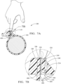
- FIGs. 7A and 7B illustrate an example operation of the release of the pawl mechanism 110 where the tip of a finger of a user is pressed against the release feature 236, causing the pawl 216 to hinge at the hinged connection 218 relative to the locking head 108, disengaging the pawl teeth 220 of the pawl 216 from the serrations 602 of the tail end 106 of the pawl-latching device 100.
- the tip of a release tool e.g., an industry-standard flat-blade screwdriver
- another object may be used to release the pawl mechanism 110 from engagement with the strap serrations 602 of the elongated strap 102.
- FIGs. 8-14B illustrate a second example implementation of an injection molded pawl-latching device 800 configured for reducing warpage defects and sinks of pawl teeth profiles.
- the second example implementation is similar to the first example implementation of a pawl-latching device 100 illustrated in FIGs. 1-7B and described above, except as detailed below.
- the pawl-latching device 800 includes an elongated strap 102, a head end 104, a tail end 106 (having a plurality of serrations 602 (illustrated in FIG.
- a locking head 108 having a top side 202, a bottom side 204, a slot 206, a first channel 208, a second channel 210, a rear wall 232, and a front wall 234), and a buckle 212 (having a buckle channel 214).
- the pawl-latching device 800 further includes a pawl mechanism 810 within the locking head 108.
- the pawl mechanism 810 having a pawl 816 with pawl teeth 820, a front side 822, a back side 824, a first side 826, a second side 828, a top side 830, a bottom side 802, a pivot member 804, a stop surface 806, a pivot member left side 808, a pivot member right side 811, a pivot member center portion 812, and a pivot member notch 814.
- a notch may not be present in the pivot member.
- the pawl 816 is connected to (e.g., tethered inside) the locking head 108, forming a hinged connection 818 within the second channel 210 of the slot 206.
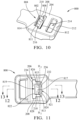
- the hinged connection 818 defines a hinge axis (H 2 ), as illustrated in FIG. 11 .
- the pawl 816 may be configured to pivot about the hinge axis, relative to the locking head 108, as illustrated in FIG. 14B .
- the inclusion of the notch 814 in the pivot member 804 may prevent sinking and warping, while enabling the pivot member 804 to function to enhance the rotation of the pawl 816 relative to the locking head 108.
- the pawl teeth 820 of the pawl-latching device 800 may be configured to engage the plurality of serrations 602 on the tail end 106 of the elongated strap 102 when a portion of the tail end 106 of the elongated strap 102 may be disposed within the first channel 208. For example, when the pawl-latching device 800 is secured around a bundle 604, as illustrated in FIGs. 14A and 14B .
- the strap 102 of the pawl-latching device 800 is configured to wrap around the bundle 604, and the tail end 106 of the strap 102 may be inserted through the first channel 208 in a first direction such that serrations 602 on the strap 102 face the pawl teeth 820 of the pawl 816 located in the second channel 210.
- the strap 102 moves longitudinally through the first channel 208 (as indicated by arrow 1406 in FIG.
- the angled portion of the serrations 602 engage the angled portion of the pawl teeth 820 on the pawl 816, causing the pawl 816 to rotate away from the strap 102 about its hinged connection 818 to the locking head 108 (as indicated by arrow 1408 in FIG. 14B ).
- the pawl 816 may include a release feature 836 (e.g., release feature 236 in FIG. 2 ).
- the release feature 836 may be defined by an unlocking tab 838 extending from the top side 830 of the pawl 816, spaced apart from at least one of the front side 822, the second side 828, and the first side 826 of the pawl 816.
- the spacing of the unlocking tab 838 apart from one or more of the front side 822, the second side 828, or the first side 826 may prevent, or otherwise result in the avoidance of geometry that contributes to, sinking and warping. Any suitable shape for the unlocking tab 838 can be used. In FIGs.
- the unlocking tab 838 is illustrated as a single wall.
- the unlocking tab 838 may be a multi-walled structure (e.g., a three-walled structure having a fore wall, a first side wall, and a second side wall), with the fore wall merged with upper portions of the first side wall and the second side wall to form a U-shaped structure defined around at least one feature channel in the back face of the release feature extending to the back side of the pawl, as illustrated with respect to the aspect of FIGs. 1-7B .
- the unlocking tab 838 may be in the shape of an "I" beam.
- the unlocking tab 838 may include two walls forming a V-shape, may include four or more walls forming a shape suitable to fit the contour of the release tool, and the like.
- the unlocking tab 838 may be spaced apart from the front side 822 of the pawl 816 to define a recess 840 for receiving a tip of a user's finger (as illustrated in FIGs. 7A and 7B with respect to pawl-latching device 100), the tip of a release tool (e.g., an industry-standard flat-blade screwdriver) or another object usable to release the pawl mechanism 810 from engagement with the strap serrations 602 of the elongated strap 102.
- a release tool e.g., an industry-standard flat-blade screwdriver
- the top side 830 may be generally flush with or recessed below a top side 202 of the locking head and the pawl 816 is at least substantially contained within the locking head 108.
- one or more of the pawl or release feature may extend beyond the top side of the locking head, such that the pawl and/or locking head protrudes longitudinally out of the second channel.
- a first channel 813 and a second channel 815 may be defined in the pawl 816.
- the first channel 813 extends from the top side 830, towards the bottom side 802 of the pawl 816.
- the second channel 815 extends from the top side 830, towards the bottom side 802 of the pawl 816.
- the first channel 813 and the second channel 815 define a support wall 817 therebetween, the support wall 817 connecting at a first end with a front portion 819 of the pawl 816 and at a second end with a rear portion 821 of the pawl 816.
- the pawl teeth 820 may be defined in the front portion 819.
- the pawl 816 includes an I-shaped beam structure.
- the inclusion of the first channel 813 and the second channel 815 may prevent a change in geometry that contributes to sinking and warping.
- the support wall 817 may function to reinforce front portion 819 relative to the rear portion 821 to provide increased wedging strength during high-loop tensile-strength applications. This may provide reinforcement strength to the pawl 816 for disengaging the pawl teeth 820, such as, when the pawl teeth 820 are compressively engaged with the serrations 602 on the tail end 106 of the strap 102 and a user's finger or a release tool applies a force against the release feature 836 to move the pawl 216 away from the strap 102.
- the pawl mechanism 810 of the pawl-latching device 800 may be configured to operate similarly to the release of the pawl mechanism 110 of the pawl-latching device 100 illustrated in FIGs. 7A and 7B , where the tip of a finger of a user is illustrated pressed against the release feature, causing the pawl to hinge at the hinged connection relative to the locking head and disengaging the pawl teeth of the pawl from the serrations of the tail end of the pawl-latching device.
- the tip of a release tool e.g., an industry-standard flat-blade screwdriver
- another object may be usable in lieu of the tip of a finger of a user.
- FIGs. 15-20B illustrate a third example implementation of an injection molded pawl-latching device 1500 configured for reducing warpage defects and sinks of pawl teeth profiles.
- the third example implementation is similar to the first example implementation of a pawl-latching device 100 illustrated in FIGs. 1-7B and described above, except as detailed below.
- the pawl-latching device 1500 includes an elongated strap 102, a head end 104, a tail end 106 (having a plurality of serrations 602), and a locking head 108 (having a top side 202, a bottom side 204, a slot 206, a first channel 208, a second channel 210, a rear wall 232, and a front wall 234).
- the pawl-latching device 1500 further includes a pawl mechanism 1510 within the locking head 108.
- the pawl mechanism 1510 having a pawl 1516 with pawl teeth 1520, a front side 1522, a back side 1524, a first side 1526, a second side 1528, a top side 1530, a bottom side 1502, a pivot member 1504, a stop surface 1506, a pivot member left side 1508, a pivot member right side 1511, a pivot member center portion 1512, and a pivot member notch 1514.
- a notch may not be present in the pivot member.
- the pawl 1516 is connected to (e.g., tethered inside) the locking head 108, forming a hinged connection 1518 within the second channel 210 of the slot 206.
- the hinged connection 1518 defines a hinge axis (H 3 ), as illustrated in FIG. 18 .
- the pawl 1516 may be configured to pivot relative to the locking head 108 at the hinge axis, as illustrated in FIG. 20B .
- the inclusion of the pivot member notch 1514 in the pivot member 1504 may result in the avoidance of geometry that contributes to sinking and warping, while enabling the pivot member 1504 to function to limit the rotation of the pawl 1516 relative to the locking head 108.
- the pawl-latching device 1500 may include an open cavity 1550 defined in the pawl 1516, for example, as illustrated in FIGs. 17 , 19, and 20B .
- the open cavity 1550 may extend from an open bottom 1552 in the notch 1514 into the pawl 1516 in the direction of the top side 1530 of the pawl 1516.
- the open cavity 1550 may include a top wall 1554 defined in a top portion 1556 of the pawl 1516, the top wall 1554 opposite the open bottom 1552.
- the open cavity 1550 may further include a back wall 1558 opposite a front wall 1560 and a first side wall 1562 opposite a second side wall 1564.
- the back wall 1558, the front wall 1560, the first side wall 1562, and the second side wall 1564 connect to the top wall 1554 to define the open cavity 1550.
- a thickness of the back wall 1558 may be generally uniform with a thickness of at least one of the front wall 1560, the first side wall 1562, or the second side wall 1564.
- a thickness of the first side wall 1562 may be generally uniform, with a thickness of at least one of the back wall 1558, the front wall 1560, or the second side wall 1564.
- the thicknesses of the back wall 1558, the front wall 1560, the first side wall 1562, and the second side wall 1564 are generally uniform.
- the inclusion of the open cavity 1550 in the pawl 1516 may result in the avoidance of geometry that contributes to sinking and warping.
- the pawl teeth 1520 of the pawl-latching device 1500 may be configured to engage the plurality of serrations 602 on the tail end 106 of the elongated strap 102 when a portion of the tail end 106 of the elongated strap 102 is disposed within the first channel 208. For example, when the pawl-latching device 1500 is secured around a bundle 604, as illustrated in FIGs. 20A and 20B .
- the strap 102 of the pawl-latching device 1500 is configured to wrap around the bundle 604, and the tail end 106 of the strap 102 is inserted through the first channel 208 in a first direction such that serrations 602 on the strap 102 face the pawl teeth 1520 of the pawl 1516 located in the second channel 210.
- the angled portion of the serrations 602 engage the angled portion of the pawl teeth 1520 on the pawl 1516, causing the pawl 1516 to rotate away from the strap 102 about its hinged connection 1518 to the locking head 108 (as indicated by arrow 2008 in FIG. 20B ).
- the pawl 1516 may include a release feature 1536 (e.g., release feature 236 in FIG. 2 ).
- the release feature 1536 may be defined by a flange 1538 extending from the top side 1530 of the pawl 1516, spaced apart from at least one of the front side 1522, the second side 1528, and the first side 1526 of the pawl 1516.
- the spacing of the flange 1538 apart from one or more of the front side 1522, the second side 1528, or the first side 1526 may result in the avoidance of geometry that contributes to sinking and warping. Any suitable shape for the flange 1538 can be used. In FIGs.
- the flange 1538 is illustrated as a single wall.
- the flange 1538 may be a multi-walled structure (e.g., a three-walled structure having a fore wall, a first side wall, and a second side wall), with the fore wall merged with upper portions of the first side wall and the second side wall to form a U-shaped structure defining at least one feature channel in the back face of the release feature extending to the back side of the pawl, as illustrated with respect to the aspect of FIGs. 1-7B .
- the flange 1538 may include two walls forming a V-shape, may include four or more walls forming a shape suitable to fit the contour of the release tool, and the like.
- the top side 1530 may be generally flush with or recessed below a top side 202 of the locking head and the pawl 1516 is at least substantially contained within the locking head 108.
- one or more of the pawl or release feature may extend beyond the top side of the locking head, such that the pawl and/or locking head protrudes longitudinally out of the second channel.
- the flange 1538 may be spaced apart from the front side 1522 of the pawl 1516 to define a recess 1540 for receiving a tip of a user's finger (as illustrated in FIGs. 7A and 7B with respect to pawl-latching device 100), the tip of a release tool (e.g., an industry-standard flat-blade screwdriver) or another object usable to release the pawl mechanism 1510 from engagement with the strap serrations 602 of the elongated strap 102.
- the pawl mechanism 1510 of the pawl-latching device 1500 may be configured to operate similarly to the release of the pawl mechanism 110 of the pawl-latching device 100 illustrated in FIGs.
- the tip of a finger of a user is illustrated pressed against the release feature, causing the pawl to hinge at the hinged connection relative to the locking head and disengaging the pawl teeth of the pawl from the serrations of the tail end of the pawl-latching device.
- the tip of a release tool e.g., an industry-standard flat-blade screwdriver
- another object may be usable in lieu of the tip of a finger of a user.
- a portion of the tail end 106 of the pawl-latching device 100 may be removed, for example, by a tension and cutoff cable tie tool or other such installation tool (not illustrated).
- a tension and cutoff cable tie tool or other such installation tool (not illustrated).
- an installation tool can be used to apply tension to the pawl-latching device and also shear off excess length of the strap that extends above the top side of the locking head.
- Such an installation tool may operate by applying tension to the pawl-latching device by pulling the strap while pushing on the top side of the locking head and using a blade to shear the strap.
- the pawl rotates toward the strap, enabling the pawl teeth on the pawl to engage the serrations on the strap and secure the pawl-latching device in place. Because the pawl-latching device is tensioned around the bundle, when the strap is sheared, the remaining strap tension is momentarily released until the pawl teeth engage serrations on the strap; thereby moving the strap in a reverse direction through the first channel and toward the bundle.
- the installation tool can shear the strap substantially flush with the top side of the locking head to substantially remove any protruding, sharp edges on the strap that could pose a risk of injury to a user or damage to adjacent routed bundles, hoses, etc.
- "at least one of: a, b, or c” is intended to cover a, b, c, a-b, a-c, b-c, and a-b-c, as well as any combination with multiples of the same element (e.g., a-a, a-a-a, a-a-b, a-a-c, a-b-b, a-c-c, b-b, b-b-b, b-b-c, c-c, and c-c-c or any other ordering of a, b, and c).
Landscapes
- Engineering & Computer Science (AREA)
- Mechanical Engineering (AREA)
- Clamps And Clips (AREA)
- Package Frames And Binding Bands (AREA)
- Buckles (AREA)
- Casings For Electric Apparatus (AREA)
Description
- Pawl-latching devices (e.g., cable ties, clips, clamps) are plastic injection molded parts that have a long history of use for securing elongated items (e.g., wires, cables, hoses, tubing, conduits) in a bundle. A variety of different types of defects may occur in molded parts produced using conventional injection molding processes.
- A first type of defect is often referred to as a "warpage defect" or "warp." A molded part that includes uneven wall thicknesses may experience a warpage defect because of stresses in step transitions (e.g., part wall sections) between the varying wall thicknesses, where the slower cooling of a thicker portion of the molded part, which is located adjacent to a thinner portion of the molded part (which cools faster), results in the warping of the thinner portion of the molded part. The thick sections will shrink more than the thin sections, causing the thin sections to be pulled towards (warp towards) the thick sections. A second type of defect is often referred to as a "sink" or "sink mark." As a molded part cools, the plastic first solidifies at the surface of the mold, and then the solidification moves inward into the part until the entire part has solidified. The thicker the part, the longer the part will take to solidify. As a result, the centers of the thickest portions of the part may still be molten when the part is ejected from the mold. During cooling of the thickest portions of a molded part, an inward pulling stress can develop that results in sinks defined on the outer surfaces of the part. Defects in molded parts, particularly those that occur in functional features, may affect the performance of the part.
- To avoid these types of defects, a manufacturer may spend considerable time monitoring the quality of the parts ejected from the molds to determine if such deformities exist and what changes to the molding process are needed to prevent such deformities. These changes may include, for example, adjusting (e.g., increasing) the hold time, adjusting the holding pressure, adjusting a cooling temperature of the molds, and the like. Such changes may result in a slowing of the production of parts and may result in reduced production quantities output.
- In the molding of pawl-latching devices, warp and sink defects in pawl teeth profiles are undesirable because they impact the visual appearance of the products produced. Further, as discussed above, such warps and sinks could further result in poor product performance issues, for example, by potentially reducing the pawl teeth-to-strap serration engagement, possibly lowering the retention strength provided by the pawl-latching device when secured around elongate items.
- Publication
GB 1 519 233 A - This document describes techniques and apparatuses directed at improved pawl-latching devices.
- In an aspect, disclosed is a pawl-latching device that includes an elongated strap with a plurality of serrations and a head. The head includes a slot, a pawl, and a pivot member. The slot extends through the head and includes a first channel conjoined with a second channel. The first channel is configured to receive the elongated strap. The pawl is disposed within the second channel of the slot, positioned internally to the head. The pawl includes a front side, a first side, a second side, a back side, a top side, and a bottom side. The pawl further has multiple pawl teeth defined in the front side that are configured to engage the plurality of serrations on the elongated strap when the elongated strap is disposed within the first channel. The pawl connects to the head at a hinged connection. The hinged connection defines a hinge axis relative to the head for the pawl to rotate about. The pivot member is defined in the bottom side of the pawl. The pivot member has a stop surface configured to contact a rear wall of the second channel when the elongated strap is disposed within the first channel and the pawl teeth engage the plurality of serrations in the elongated strap. The pivot member has a first side opposite a second side, and a notch in a center portion defined between the first side and the second side. The head further comprises the hinged connection, the hinged connection connecting the back side of the pawl to the head at the second channel of the slot.
- The details of one or more aspects of techniques and apparatuses directed at improved pawl-latching devices are described with reference to the following Drawings, in which the use of the same numbers in different instances may indicate like features and/or components.
-
FIG. 1 is a top, perspective view of a first example implementation of an improved pawl-latching device according to implementations described herein; -
FIG. 2 is a partial, top perspective view of the pawl-latching device ofFIG. 1 ; -
FIG. 3 is a partial, bottom perspective view of the pawl-latching device ofFIG. 1 ; -
FIG. 4 is a top plan view of the locking head of the pawl-latching device ofFIG. 1 ; -
FIG. 5 is a side sectional view of the locking head ofFIG. 4 , taken along section line 5-5; -
FIG. 6A is a side sectional looped and tensioning view of the pawl-latching device ofFIG. 1 ; -
FIG. 6B is an enlarged view of the pawl-latching device illustrated inFIG. 6A , enlarged for magnification purposes; -
FIG. 7A is a side sectional looped view of the pawl-latching device ofFIG. 6A , illustrating an operation of the release feature; -
FIG. 7B is an enlarged view of the pawl-latching device illustrated inFIG. 7A , enlarged for magnification purposes; -
FIG. 8 is a top perspective view of a second example implementation of an improved pawl-latching device according to implementations described herein -
FIG. 9 is a partial, top perspective view of the pawl-latching device ofFIG. 8 ; -
FIG. 10 is a partial, bottom perspective view of the pawl-latching device ofFIG. 8 ; -
FIG. 11 is a top plan view of the locking head of the pawl-latching device ofFIG. 8 ; -
FIG. 12 is a side sectional view of the locking head ofFIG. 11 , taken along section line 12-12; -
FIG. 13 is a side sectional view of the locking head ofFIG. 11 , taken along section line 13-13; -
FIG. 14A is a side sectional looped and tensioning view of the pawl-latching device ofFIG. 8 ; -
FIG. 14B is an enlarged view of the pawl-latching device illustrated inFIG. 14A , enlarged for magnification purposes; -
FIG. 15 is a top perspective view of a third example implementation of an improved pawl-latching device according to implementations described herein; -
FIG. 16 is a partial, top perspective view of the pawl-latching device ofFIG. 15 ; -
FIG. 17 is a partial, bottom perspective view of the pawl-latching device ofFIG. 15 ; -
FIG. 18 is a top plan view of the locking head of the pawl-latching device ofFIG. 15 ; -
FIG. 19 is a side sectional view of the locking head ofFIG. 18 , taken along section line 19-19; -
FIG. 20A is a side sectional looped and tensioning view of the pawl-latching device ofFIG. 15 ; and -
FIG. 20B is an enlarged view of the pawl-latching device illustrated inFIG. 20A , enlarged for magnification purposes. - This document describes techniques and apparatuses for improved injection molded pawl-latching devices. Aspects of the present disclosure further address technical problems associated with warpage defects and sinks of pawl teeth profiles, and in particular, may enable one or more of maintaining of pawl teeth-to-strap serration engagement of pawl-latching devices, maintaining the retention strength provided by the pawl-latching device when secured around elongate items, decreasing manufacturing costs associated with injection molded pawl-latching devices, and/or increasing the production speed of injection molded pawl-latching devices.
- An example pawl-latching device is described herein that includes a head end and a tail end. The head end includes a locking head and the tail end includes an elongated strap that extends from the locking head. The elongated strap may be configured for insertion through the locking head to form a loop (e.g., a loop around a bundle of elongate objects). The term "bundle" used herein refers to any object or objects that may be secured by a pawl-latching device. Common examples of a bundle, which is securable via an example pawl-latching device, include a bundle of wires, cables, lines, hoses, tubing, conduit, or other objects (e.g., elongate objects) that need securing. Additional example implementations of securing a bundle include securing vines to trellises, small trees to stakes, animal fencing to poles, etc. The locking head includes a pawl mechanism configured for engaging strap serrations defined on the elongated strap, thereby retaining the strap relative to the locking head. The locking head may include a release feature (e.g., unlocking tab, unlocking lever) configured to permit the pawl mechanism to be released from engagement with the strap serrations of the strap, thereby enabling the pawl-latching device to be removed from securing the bundle. The release feature may be configured to enable an operator to digitally manipulate (e.g., utilizing a finger of the operator, utilizing a tool) the release feature to disengage the pawl teeth on the pawl from engagement with the strap serrations. Disengagement of the pawl teeth from the strap serrations permits the elongated strap to be withdrawn from the locking head and the pawl-latching device to be removed from securing the bundle.
- The pawl-latching device may be formed to include at least one notch defined in a portion of the pivot member of the pawl for reducing warpage defects and sinks of pawl teeth profiles of the pawl. In addition, the pawl-latching device may be formed to include an open cavity defined in the bottom of the pawl for reducing warpage defects and sinks of pawl teeth profiles of the pawl. Further, the pawl-latching device may be formed to provide a generally uniform wall thickness in the pawl for reducing warpage defects and sinks of pawl teeth profiles of the pawl. In aspects, the pawl-latching device may be formed with a release feature structure configured for reducing warpage defects and sinks of pawl teeth profiles of the pawl. In other aspects, the pawl-latching device may be formed to include a strut and channels defined on a back side of the pawl for reducing warpage defects and sinks of pawl teeth profiles of the pawl. In further aspects, the pawl-latching device may be formed to include downwardly extending channels defined within the body of the pawl that defines a beam therebetween for reducing warpage defects and sinks of pawl teeth profiles of the pawl. One or more of these pawl-latching devices, as described in detail below, may reduce the occurrence of warpage defects and sinks of pawl teeth profiles in injection molded pawl-latching devices, thereby improving pawl-to-strap-serration engagement strength (also referred to as loop tensile strength) relative to conventional cable-tie pawls. These are but a few examples of how the described techniques and apparatuses may be used to reduce warpage defects and sinks of pawl teeth profiles in injection molded pawl-latching devices. Other examples and implementations are described throughout this document.
-
FIGs. 1-7B illustrate a first example implementation of an injection molded pawl-latching device 100 (e.g., cable-tie assembly) configured for reducing warpage defects and sinks of pawl teeth profiles. The pawl-latchingdevice 100 includes an elongated strap 102 (or band) having ahead end 104, and atail end 106 that is opposite thehead end 104. The pawl-latchingdevice 100 also includes a lockinghead 108 integrally connected to thehead end 104 of thestrap 102. Thestrap 102 also includes a plurality of serrations on at least one lengthwise side of thestrap 102, which may be configured to engage apawl mechanism 110 within the lockinghead 108. For example, the plurality of serrations are illustrated inFIG. 6B asserrations 602, which are disposed on a bottom side of thestrap 102. As is described in more detail below, thepawl mechanism 110 is disposed within an interior of the lockinghead 108. The pawl-latchingdevice 100 described herein is merely an example in which the pawl-latching device can be implemented; any suitable pawl-latching device can be used to implement the pawl-latching device, such as clips and clamps. - The locking
head 108 has atop side 202 and abottom side 204, with aslot 206 defined therebetween. Theslot 206 has afirst channel 208 and asecond channel 210 conjoined with thefirst channel 208. Theslot 206 extends through the lockinghead 108. Thefirst channel 208 may be configured to receive theelongated strap 102, such as thetail end 106 of thestrap 102. Theslot 206 may include arear wall 232 opposite afront wall 234. Thepawl mechanism 110 may be disposed within thesecond channel 210 of theslot 206 such that when thestrap 102 is disposed within thefirst channel 208, thepawl mechanism 110 engages thestrap 102 to allow unidirectional movement of thestrap 102 through thefirst channel 208 in a first direction and resist movement of thestrap 102 in an opposite direction. The lockinghead 108 may further include abuckle 212 defining abuckle channel 214 through the lockinghead 108. Thebuckle 212 provides an alternative attachment point, for example, as a slot configured to receive the elongated strap of another pawl-latching device (not illustrated). - The
pawl mechanism 110 includes apawl 216 connected to (e.g., tethered inside) the lockinghead 108, and forming a hingedconnection 218 within thesecond channel 210 of theslot 206. The hingedconnection 218 defines a hinge axis (H), as illustrated inFIG. 4 . Thepawl 216 may be configured to pivot relative to the lockinghead 108 at the hinge axis, as illustrated inFIG. 6B . Thepawl 216 may be disposed within thesecond channel 210 of theslot 206 and positioned internally to the lockinghead 108. Thepawl 216 includesmultiple pawl teeth 220 defined on afront side 222 of thepawl 216. Thepawl teeth 220 face thefirst channel 208. Thepawl teeth 220 include protrusions extending from thepawl 216 toward thefirst channel 208 and may be angled toward one end of thefirst channel 208, such as toward the top side 202 (outer surface) of the lockinghead 108. Thepawl teeth 220 may be configured to engage the plurality of serrations 602 (illustrated inFIG. 6B ) on thetail end 106 of theelongated strap 102 when a portion of thetail end 106 of theelongated strap 102 is disposed within thefirst channel 208, as illustrated inFIG. 6A and FIG. 6B . Thepawl 216 further includes aback side 224 opposite thefront side 222, afirst side 226 opposite a second side 228, and atop side 230 opposite abottom side 302. - A
pivot member 304 is defined at or in thebottom side 302 of thepawl 216. Thepivot member 304 may function to stop the bottom of the pawl from moving beyond the vertical ledge where hinge is attached when moderate strap tension is applied, may anchor the base of the pawl against the ledge, may reinforce the thin hinge for increased strap tension, may transform into a fulcrum or pivot for further pawl rotation at higher applied loop tension, and may add additional wedging to the pawl for optimal applied tension (at this highest tension level the pivot compresses and deforms and the hinges stretches, and the pivot provides a cam effect). - The
pivot member 304 having astop surface 306 configured to contact therear wall 232 of the slot 206 (e.g., second channel 210) (e.g., a ledge of the pawl hinge) when theelongated strap 102 is disposed within thefirst channel 208 and thepawl teeth 220 engage the plurality ofserrations 602 in theelongated strap 102 under load (e.g., when the strap is moderately tensioned around a bundle), as illustrated inFIG. 6B . InFIG. 3 , thepivot member 304 has a length (L). The length may extend such that it is generally parallel to the hinge axis (H). Thepivot member 304 may be a single element or may be divided (e.g., bifurcated, notched) into two or more segments. In the aspect illustrated inFig. 3 , thepivot member 304 has leftside 308 opposite aright side 310, with acenter portion 312 defined therebetween. Thepivot member 304 further includes anotch 314, which may be defined along the length in thecenter portion 312. In aspects, thenotch 314 may be radial to the hinge axis (H). The inclusion of thenotch 314 in thepivot member 304 may result in the avoidance of geometry that contributes to sinking and warping, while enabling thepivot member 304 to function to limit the rotation of thepawl 216 relative to the lockinghead 108. - The
pawl 216 may be positioned internal to the lockinghead 108 such that the pawl 216 (e.g., therelease feature 236 of the pawl 216) does not extend above thetop side 202 of the locking head 108 (e.g., thepawl 216 does not protrude longitudinally out of theslot 206/second channel 210) and/or such that the pawl 216 (e.g.,bottom side 302, pivot member 304) does not extend below abottom side 204 of the locking head 108 (e.g., thepawl 216 does not protrude longitudinally out of theslot 206/second channel 210). In such a configuration, illustrated inFIGs. 1-7B , therelease feature 236 may be generally flush with or recessed below thetop side 202 of the lockinghead 108 and thepawl 216 at least substantially contained within the lockinghead 108. In other aspects (not illustrated), one or more of the pawl or release feature may extend beyond the top side of the locking head, such that the pawl and/or locking head protrudes longitudinally out of the second channel. - The
pawl 216 may include therelease feature 236 defined by awalled structure 238 integrally connected to thepawl 216 at thetop side 230 of thepawl 216. Thewalled structure 238 may be spaced apart from at least one of thefront side 222 of thepawl 216 to define arecess 240 for receiving a tip of a user's finger (further illustrated inFIGs. 7A and 7B ), the tip of a release tool (e.g., an industry-standard flat-blade screwdriver), or another object usable to release thepawl mechanism 110 from engagement with thestrap serrations 602 of theelongated strap 102. Any suitable shape for thewalled structure 238 can be used. InFIGs. 1-7B , thewalled structure 238 is illustrated as a multi-walled structure (e.g., three-walled structure) having afore wall 242, afirst side wall 248, and asecond side wall 250. In aspects, thefore wall 242 is merged with upper portions of thefirst side wall 248 and thesecond side wall 250 to form a U-shaped structure defining afeature channel 502 defined in theback wall 246 of therelease feature 236 extending to theback side 224 of thepawl 216. The presence of thefeature channel 502 may result in the avoidance of geometry that contributes to sinking and warping. In other examples, thewalled structure 238 may be a single wall, may include two walls forming a V-shape, may include four or more walls forming a shape suitable to fit the contour of the release tool, and the like. - The
release feature 236 extends from thetop side 230 of thepawl 216. The release feature 236 (e.g., the walled structure 238) may be spaced apart from one or more of thefront side 222, thefirst side 226, and the second side 228 of thepawl 216. The spacing of the release feature 236 (e.g., the walled structure 238) apart from one or more of thefront side 222, the second side 228, or thefirst side 226 may result in the avoidance of geometry that contributes to sinking and warping. - The
first side wall 248 and thesecond side wall 250 may extend from thetop side 230 of thepawl 216 along theback side 224 of thepawl 216 to the hingedconnection 218. The elongatedfirst side wall 248 and elongatedsecond side wall 250 may function as struts configured to reinforce the connection between thepawl 216 and the hingedconnection 218 to provide increased wedging strength during high-loop tensile-strength applications. For example, thefirst side wall 248 may define afirst strut 252 on theback side 224 of thepawl 216, thefirst strut 252 extending from the hingedconnection 218 to thetop side 230 of thepawl 216. Likewise, thesecond side wall 250 may define asecond strut 254 on theback side 224 of thepawl 216, thesecond strut 254 extending from the hingedconnection 218 to thetop side 230 of thepawl 216. In aspects, thesecond strut 254 may be spaced apart from thefirst strut 252, defining at least onechannel 256 therebetween. Thefore wall 242 may also be configured to reinforce thefirst side wall 248 andsecond side wall 250 to provide increased wedging strength during high-loop tensile-strength applications. Further, integration of thefirst side wall 248, thesecond side wall 250, and thefore wall 242 provides reinforcement strength to thefore wall 242 for disengaging thepawl teeth 220 when thepawl teeth 220 are compressively engaged with theserrations 602 on thetail end 106 of thestrap 102 and a user's finger or a release tool applies a force against thefore wall 242 of therelease feature 236 to move thepawl 216 away from thestrap 102. -
FIGs. 6A and 6B illustrate thepawl teeth 220 engaging theserrations 602 on thetail end 106 of theelongated strap 102 when a portion of thetail end 106 of thestrap 102 disposed within thefirst channel 208 when the pawl-latchingdevice 100 is secured around abundle 604. Thestrap 102 of the pawl-latchingdevice 100 is illustrated wrapped around thebundle 604, and thetail end 106 of thestrap 102 is inserted through thefirst channel 208 in a first direction, such thatserrations 602 on thestrap 102 face thepawl teeth 220 of thepawl 216 located in thesecond channel 210. In such a configuration, as thestrap 102 moves longitudinally through the first channel 208 (as indicated by arrow 606), the angled portion of theserrations 602 engage the angled portion of thepawl teeth 220 on thepawl 216, causing thepawl 216 to rotate away from thestrap 102 about its hingedconnection 218 to the lockinghead 108, as indicated byarrow 608. -
FIGs. 7A and 7B illustrate an example operation of the release of thepawl mechanism 110 where the tip of a finger of a user is pressed against therelease feature 236, causing thepawl 216 to hinge at the hingedconnection 218 relative to the lockinghead 108, disengaging thepawl teeth 220 of thepawl 216 from theserrations 602 of thetail end 106 of the pawl-latchingdevice 100. In aspects, the tip of a release tool (e.g., an industry-standard flat-blade screwdriver) or another object may be used to release thepawl mechanism 110 from engagement with thestrap serrations 602 of theelongated strap 102. -
FIGs. 8-14B illustrate a second example implementation of an injection molded pawl-latchingdevice 800 configured for reducing warpage defects and sinks of pawl teeth profiles. The second example implementation is similar to the first example implementation of a pawl-latchingdevice 100 illustrated inFIGs. 1-7B and described above, except as detailed below. Thus, the pawl-latchingdevice 800 includes anelongated strap 102, ahead end 104, a tail end 106 (having a plurality of serrations 602 (illustrated inFIG. 14B )), a locking head 108 (having atop side 202, abottom side 204, aslot 206, afirst channel 208, asecond channel 210, arear wall 232, and a front wall 234), and a buckle 212 (having a buckle channel 214). - The pawl-latching
device 800 further includes apawl mechanism 810 within the lockinghead 108. Thepawl mechanism 810 having apawl 816 withpawl teeth 820, afront side 822, aback side 824, afirst side 826, asecond side 828, atop side 830, abottom side 802, apivot member 804, astop surface 806, a pivot member leftside 808, a pivot memberright side 811, a pivotmember center portion 812, and apivot member notch 814. In aspects, a notch may not be present in the pivot member. - The
pawl 816 is connected to (e.g., tethered inside) the lockinghead 108, forming a hingedconnection 818 within thesecond channel 210 of theslot 206. The hingedconnection 818 defines a hinge axis (H2), as illustrated inFIG. 11 . Thepawl 816 may be configured to pivot about the hinge axis, relative to the lockinghead 108, as illustrated inFIG. 14B . The inclusion of thenotch 814 in thepivot member 804 may prevent sinking and warping, while enabling thepivot member 804 to function to enhance the rotation of thepawl 816 relative to the lockinghead 108. - The
pawl teeth 820 of the pawl-latchingdevice 800 may be configured to engage the plurality ofserrations 602 on thetail end 106 of theelongated strap 102 when a portion of thetail end 106 of theelongated strap 102 may be disposed within thefirst channel 208. For example, when the pawl-latchingdevice 800 is secured around abundle 604, as illustrated inFIGs. 14A and 14B . Thestrap 102 of the pawl-latchingdevice 800 is configured to wrap around thebundle 604, and thetail end 106 of thestrap 102 may be inserted through thefirst channel 208 in a first direction such thatserrations 602 on thestrap 102 face thepawl teeth 820 of thepawl 816 located in thesecond channel 210. In such a configuration, as thestrap 102 moves longitudinally through the first channel 208 (as indicated byarrow 1406 inFIG. 14A ), the angled portion of theserrations 602 engage the angled portion of thepawl teeth 820 on thepawl 816, causing thepawl 816 to rotate away from thestrap 102 about its hingedconnection 818 to the locking head 108 (as indicated byarrow 1408 inFIG. 14B ). - The
pawl 816 may include a release feature 836 (e.g.,release feature 236 inFIG. 2 ). In the aspect illustrated inFIGs. 8-14B , therelease feature 836 may be defined by an unlockingtab 838 extending from thetop side 830 of thepawl 816, spaced apart from at least one of thefront side 822, thesecond side 828, and thefirst side 826 of thepawl 816. The spacing of the unlockingtab 838 apart from one or more of thefront side 822, thesecond side 828, or thefirst side 826 may prevent, or otherwise result in the avoidance of geometry that contributes to, sinking and warping. Any suitable shape for the unlockingtab 838 can be used. InFIGs. 8-14B , the unlockingtab 838 is illustrated as a single wall. The unlockingtab 838 may be a multi-walled structure (e.g., a three-walled structure having a fore wall, a first side wall, and a second side wall), with the fore wall merged with upper portions of the first side wall and the second side wall to form a U-shaped structure defined around at least one feature channel in the back face of the release feature extending to the back side of the pawl, as illustrated with respect to the aspect ofFIGs. 1-7B . In other examples, the unlockingtab 838 may be in the shape of an "I" beam. In further examples, the unlockingtab 838 may include two walls forming a V-shape, may include four or more walls forming a shape suitable to fit the contour of the release tool, and the like. The unlockingtab 838 may be spaced apart from thefront side 822 of thepawl 816 to define arecess 840 for receiving a tip of a user's finger (as illustrated inFIGs. 7A and 7B with respect to pawl-latching device 100), the tip of a release tool (e.g., an industry-standard flat-blade screwdriver) or another object usable to release thepawl mechanism 810 from engagement with thestrap serrations 602 of theelongated strap 102. - In the configuration illustrated in
FIGs. 8-14B , thetop side 830 may be generally flush with or recessed below atop side 202 of the locking head and thepawl 816 is at least substantially contained within the lockinghead 108. In other aspects (not illustrated), one or more of the pawl or release feature may extend beyond the top side of the locking head, such that the pawl and/or locking head protrudes longitudinally out of the second channel. - In the aspect illustrated in
FIGs. 8-14B , afirst channel 813 and asecond channel 815 may be defined in thepawl 816. Thefirst channel 813 extends from thetop side 830, towards thebottom side 802 of thepawl 816. Thesecond channel 815 extends from thetop side 830, towards thebottom side 802 of thepawl 816. Thefirst channel 813 and thesecond channel 815 define asupport wall 817 therebetween, thesupport wall 817 connecting at a first end with afront portion 819 of thepawl 816 and at a second end with arear portion 821 of thepawl 816. Thepawl teeth 820 may be defined in thefront portion 819. In such a configuration, thepawl 816 includes an I-shaped beam structure. - The inclusion of the
first channel 813 and thesecond channel 815 may prevent a change in geometry that contributes to sinking and warping. Thesupport wall 817 may function to reinforcefront portion 819 relative to therear portion 821 to provide increased wedging strength during high-loop tensile-strength applications. This may provide reinforcement strength to thepawl 816 for disengaging thepawl teeth 820, such as, when thepawl teeth 820 are compressively engaged with theserrations 602 on thetail end 106 of thestrap 102 and a user's finger or a release tool applies a force against therelease feature 836 to move thepawl 216 away from thestrap 102. - The
pawl mechanism 810 of the pawl-latchingdevice 800 may be configured to operate similarly to the release of thepawl mechanism 110 of the pawl-latchingdevice 100 illustrated inFIGs. 7A and 7B , where the tip of a finger of a user is illustrated pressed against the release feature, causing the pawl to hinge at the hinged connection relative to the locking head and disengaging the pawl teeth of the pawl from the serrations of the tail end of the pawl-latching device. In aspects, the tip of a release tool (e.g., an industry-standard flat-blade screwdriver) or another object may be usable in lieu of the tip of a finger of a user. -
FIGs. 15-20B illustrate a third example implementation of an injection molded pawl-latchingdevice 1500 configured for reducing warpage defects and sinks of pawl teeth profiles. The third example implementation is similar to the first example implementation of a pawl-latchingdevice 100 illustrated inFIGs. 1-7B and described above, except as detailed below. Thus, the pawl-latchingdevice 1500 includes anelongated strap 102, ahead end 104, a tail end 106 (having a plurality of serrations 602), and a locking head 108 (having atop side 202, abottom side 204, aslot 206, afirst channel 208, asecond channel 210, arear wall 232, and a front wall 234). - The pawl-latching
device 1500 further includes apawl mechanism 1510 within the lockinghead 108. Thepawl mechanism 1510 having apawl 1516 withpawl teeth 1520, afront side 1522, aback side 1524, afirst side 1526, asecond side 1528, atop side 1530, abottom side 1502, apivot member 1504, a stop surface 1506, a pivot member leftside 1508, a pivot memberright side 1511, a pivotmember center portion 1512, and apivot member notch 1514. In aspects, a notch may not be present in the pivot member. - The
pawl 1516 is connected to (e.g., tethered inside) the lockinghead 108, forming a hingedconnection 1518 within thesecond channel 210 of theslot 206. The hingedconnection 1518 defines a hinge axis (H3), as illustrated inFIG. 18 . Thepawl 1516 may be configured to pivot relative to the lockinghead 108 at the hinge axis, as illustrated inFIG. 20B . The inclusion of thepivot member notch 1514 in thepivot member 1504 may result in the avoidance of geometry that contributes to sinking and warping, while enabling thepivot member 1504 to function to limit the rotation of thepawl 1516 relative to the lockinghead 108. - In aspects, the pawl-latching
device 1500 may include anopen cavity 1550 defined in thepawl 1516, for example, as illustrated inFIGs. 17 ,19, and 20B . Theopen cavity 1550 may extend from an open bottom 1552 in thenotch 1514 into thepawl 1516 in the direction of thetop side 1530 of thepawl 1516. Theopen cavity 1550 may include atop wall 1554 defined in atop portion 1556 of thepawl 1516, thetop wall 1554 opposite theopen bottom 1552. Theopen cavity 1550 may further include aback wall 1558 opposite afront wall 1560 and afirst side wall 1562 opposite asecond side wall 1564. In aspects, theback wall 1558, thefront wall 1560, thefirst side wall 1562, and thesecond side wall 1564 connect to thetop wall 1554 to define theopen cavity 1550. A thickness of theback wall 1558 may be generally uniform with a thickness of at least one of thefront wall 1560, thefirst side wall 1562, or thesecond side wall 1564. A thickness of thefirst side wall 1562 may be generally uniform, with a thickness of at least one of theback wall 1558, thefront wall 1560, or thesecond side wall 1564. In aspects, the thicknesses of theback wall 1558, thefront wall 1560, thefirst side wall 1562, and thesecond side wall 1564 are generally uniform. The inclusion of theopen cavity 1550 in thepawl 1516 may result in the avoidance of geometry that contributes to sinking and warping. - The
pawl teeth 1520 of the pawl-latchingdevice 1500 may be configured to engage the plurality ofserrations 602 on thetail end 106 of theelongated strap 102 when a portion of thetail end 106 of theelongated strap 102 is disposed within thefirst channel 208. For example, when the pawl-latchingdevice 1500 is secured around abundle 604, as illustrated inFIGs. 20A and 20B . Thestrap 102 of the pawl-latchingdevice 1500 is configured to wrap around thebundle 604, and thetail end 106 of thestrap 102 is inserted through thefirst channel 208 in a first direction such thatserrations 602 on thestrap 102 face thepawl teeth 1520 of thepawl 1516 located in thesecond channel 210. In such a configuration, as thestrap 102 moves longitudinally through the first channel 208 (as indicated byarrow 2006 inFIG. 20A ), the angled portion of theserrations 602 engage the angled portion of thepawl teeth 1520 on thepawl 1516, causing thepawl 1516 to rotate away from thestrap 102 about its hingedconnection 1518 to the locking head 108 (as indicated byarrow 2008 inFIG. 20B ). - The
pawl 1516 may include a release feature 1536 (e.g.,release feature 236 inFIG. 2 ). In the aspect illustrated inFIGs. 15-20B , therelease feature 1536 may be defined by aflange 1538 extending from thetop side 1530 of thepawl 1516, spaced apart from at least one of thefront side 1522, thesecond side 1528, and thefirst side 1526 of thepawl 1516. The spacing of theflange 1538 apart from one or more of thefront side 1522, thesecond side 1528, or thefirst side 1526 may result in the avoidance of geometry that contributes to sinking and warping. Any suitable shape for theflange 1538 can be used. InFIGs. 15-20B , theflange 1538 is illustrated as a single wall. Theflange 1538 may be a multi-walled structure (e.g., a three-walled structure having a fore wall, a first side wall, and a second side wall), with the fore wall merged with upper portions of the first side wall and the second side wall to form a U-shaped structure defining at least one feature channel in the back face of the release feature extending to the back side of the pawl, as illustrated with respect to the aspect ofFIGs. 1-7B . In other examples, theflange 1538 may include two walls forming a V-shape, may include four or more walls forming a shape suitable to fit the contour of the release tool, and the like. - In the configuration illustrated in
FIGs. 15-20B , thetop side 1530 may be generally flush with or recessed below atop side 202 of the locking head and thepawl 1516 is at least substantially contained within the lockinghead 108. In other aspects (not illustrated), one or more of the pawl or release feature may extend beyond the top side of the locking head, such that the pawl and/or locking head protrudes longitudinally out of the second channel. - The
flange 1538 may be spaced apart from thefront side 1522 of thepawl 1516 to define arecess 1540 for receiving a tip of a user's finger (as illustrated inFIGs. 7A and 7B with respect to pawl-latching device 100), the tip of a release tool (e.g., an industry-standard flat-blade screwdriver) or another object usable to release thepawl mechanism 1510 from engagement with thestrap serrations 602 of theelongated strap 102. Thepawl mechanism 1510 of the pawl-latchingdevice 1500 may be configured to operate similarly to the release of thepawl mechanism 110 of the pawl-latchingdevice 100 illustrated inFIGs. 7A and 7B , where the tip of a finger of a user is illustrated pressed against the release feature, causing the pawl to hinge at the hinged connection relative to the locking head and disengaging the pawl teeth of the pawl from the serrations of the tail end of the pawl-latching device. In aspects, the tip of a release tool (e.g., an industry-standard flat-blade screwdriver) or another object may be usable in lieu of the tip of a finger of a user. - After a pawl-latching
device 100 is secured around thebundle 604 and tensioned, a portion of thetail end 106 of the pawl-latchingdevice 100 may be removed, for example, by a tension and cutoff cable tie tool or other such installation tool (not illustrated). For example, an installation tool can be used to apply tension to the pawl-latching device and also shear off excess length of the strap that extends above the top side of the locking head. Such an installation tool may operate by applying tension to the pawl-latching device by pulling the strap while pushing on the top side of the locking head and using a blade to shear the strap. In such an operation, the pawl rotates toward the strap, enabling the pawl teeth on the pawl to engage the serrations on the strap and secure the pawl-latching device in place. Because the pawl-latching device is tensioned around the bundle, when the strap is sheared, the remaining strap tension is momentarily released until the pawl teeth engage serrations on the strap; thereby moving the strap in a reverse direction through the first channel and toward the bundle. Further, because the pawl and the release feature are positioned internally to the locking head, the installation tool can shear the strap substantially flush with the top side of the locking head to substantially remove any protruding, sharp edges on the strap that could pose a risk of injury to a user or damage to adjacent routed bundles, hoses, etc. - While various aspects of pawl-latching devices are described in the foregoing description and illustrated in the drawings, it is to be understood that this disclosure is not limited thereto but may be variously embodied to practice within the scope of the following claims. From the foregoing description, it will be apparent that various changes may be made without departing from the scope of the disclosure as defined by the following claims. Further, the specific features and methods disclosed are example implementations of pawl-latching devices, and other equivalent features and methods are intended to be within the scope of the appended claims. Additionally, various different aspects are described, and it is to be appreciated that each described aspect can be implemented independently or in connection with one or more other described aspects or parts thereof.
- The use of "or" and grammatically related terms indicates non-exclusive alternatives without limitation unless the context clearly dictates otherwise. As used herein, a phrase referring to "at least one of" a list of items refers to any combination of those items, including single members. As an example, "at least one of: a, b, or c" is intended to cover a, b, c, a-b, a-c, b-c, and a-b-c, as well as any combination with multiples of the same element (e.g., a-a, a-a-a, a-a-b, a-a-c, a-b-b, a-c-c, b-b, b-b-b, b-b-c, c-c, and c-c-c or any other ordering of a, b, and c).
Claims (15)
- A pawl-latching device (100; 800; 1500) comprising:an elongated strap (102) comprising a plurality of serrations (602); anda head (108), the head comprising:characterised in that the pivot member has a notch (314; 814; 1514) in a center portion (312; 812; 1512) defined between the first side (308; 808; 1508) and the second side (310; 811; 1511).a slot (206) that extends through the head (108), the slot including a first channel (208) conjoined with a second channel (210), the first channel (208) configured to receive the elongated strap (102);a pawl (216; 816; 1516) disposed within the second channel (210) of the slot (206), the pawl positioned internally to the head (108), the pawl comprising:a front side (222; 822; 1522), a first side (226; 826; 1526), a second side (228; 828; 1528), a back side (224; 824; 1524), a top side (230; 830; 1530), and a bottom side (302; 802; 1502);the pawl (216; 816; 1516) having multiple pawl teeth (220; 820; 1520) defined in the front side (222; 822; 1522), and configured to engage the plurality of serrations (602) on the elongated strap (102) when the elongated strap is disposed within the first channel (208);the pawl (216; 816; 1516) connected to the head (108) at a hinged connection (218; 818; 1518), wherein the hinged connection defines a hinge axis relative to the head (108) for the pawl (216; 816; 1516) to pivot about; anda pivot member (304; 804; 1504) defined in the bottom side (302; 802; 1502), the pivot member having a stop surface (306; 806; 1506) configured to contact a rear wall (232) of the second channel (210) when the elongated strap (102) is disposed within the first channel (208) and the pawl teeth (220; 820; 1520) engage the plurality of serrations (602) in the elongated strap (102), the pivot member (304; 804; 1504) having a first side (308; 808; 1508) opposite a second side (310; 811; 1511); andthe hinged connection (218; 818; 1518), the hinged connection connecting the back side (224; 824; 1524) of the pawl (216; 816; 1516) to the head (108) at the second channel (210) of the slot (206),
- The pawl-latching device of claim 1, wherein the pivot member (304; 804; 1504) has a length that extends generally parallel to the hinge axis.
- The pawl-latching device of claim 2, wherein the notch (314; 814; 1514) is defined along the length in the center portion (312; 812; 1512).
- The pawl-latching device of claim 1, further comprising,
an open cavity (1550) defined in the pawl (1516), and that extends into the pawl (1516), from the notch (1514), and in a direction of the top side (1530) of the pawl (1516). - The pawl-latching device of claim 4, wherein the open cavity (1550) further comprises:
a top wall (1554) defined in a top portion (1556) of the pawl (1516), and opposite an open bottom (1552) in the notch (1514), wherein connected to the top wall (1554) the open cavity (1550) further comprises:a back wall (1558) opposite a front wall (1560); anda first side wall (1562) opposite a second side wall (1564). - The pawl-latching device of claim 5,wherein a thickness of the back wall (1558) is generally uniform with a thickness of at least one of the front wall (1560), the first side wall (1562), or the second side wall (1564); orwherein a thickness of the first side wall (1562) is generally uniform with a thickness of at least one of the back wall (1558), the front wall (1560), or the second side wall (1564).
- The pawl-latching device of claim 6, wherein the thicknesses of the back wall (1558), the front wall (1560), the first side wall (1562), and the second side wall (1564) are generally uniform.
- The pawl-latching device of claim 1, wherein the pawl (216; 816; 1516) further comprises:
a release feature (236; 836; 1536) that extends from the top side (230; 830; 1530) of the pawl (216; 816; 1516) spaced apart from the front side (222; 822; 1522), the second side (228; 828; 1528), and the first side (226; 826; 1526) of the pawl (216; 816; 1516). - The pawl-latching device of claim 8, wherein the top side (230; 830; 1530) is recessed below the top side (202) of the head (108).
- The pawl-latching device of claim 9, wherein the release feature (236; 836; 1536) is recessed below the top side (202) of the head (108).
- The pawl-latching device of claim 8, wherein the release feature (236) further comprises:a fore wall (242) that faces a front wall (234) of the slot (206);a back wall (246) that faces the rear wall (232) of the slot (206); anda feature channel (502) defined in the back wall (246).
- The pawl-latching device of claim 11, wherein the release feature (236) is generally U-shaped.
- The pawl-latching device of claim 1, further comprising:
a first strut (252) on the back side (224) of the pawl (216), and that extends from the hinged connection (218) to the top side (230) of the pawl (216). - The pawl-latching device of claim 13, further comprising:
a second strut (254) on the back side (224) of the pawl (216), and that extends from the hinged connection (218) to the top side (230) of the pawl (216), wherein the second strut (254) is spaced apart from the first strut (252), and defines a channel (256) therebetween. - The pawl-latching device of claim 1, wherein the pawl (816) further comprises:a first channel (813) defined in the pawl (816), the first channel (813) that extends from the top side (830) towards the bottom side (802) of the pawl (816); anda second channel (815) defined in the pawl (816), the second channel that extends from the top side (830) towards the bottom side (802) of the pawl (816),wherein the first channel (813) and the second channel (815) define a support wall (817) therebetween, the support wall connects at a first end with a front portion (819) of the pawl (816), the support wall (817) connects at a second end with a rear portion (821) of the pawl (816).
Priority Applications (1)
| Application Number | Priority Date | Filing Date | Title |
|---|---|---|---|
| EP24217943.0A EP4501811A3 (en) | 2021-06-22 | 2022-05-12 | Pawl-latching devices |
Applications Claiming Priority (4)
| Application Number | Priority Date | Filing Date | Title |
|---|---|---|---|
| US202163213606P | 2021-06-22 | 2021-06-22 | |
| US202163214142P | 2021-06-23 | 2021-06-23 | |
| US202163257047P | 2021-10-18 | 2021-10-18 | |
| US17/659,767 US11738922B2 (en) | 2021-06-22 | 2022-04-19 | Pawl-latching devices |
Related Child Applications (2)
| Application Number | Title | Priority Date | Filing Date |
|---|---|---|---|
| EP24217943.0A Division EP4501811A3 (en) | 2021-06-22 | 2022-05-12 | Pawl-latching devices |
| EP24217943.0A Division-Into EP4501811A3 (en) | 2021-06-22 | 2022-05-12 | Pawl-latching devices |
Publications (2)
| Publication Number | Publication Date |
|---|---|
| EP4108594A1 EP4108594A1 (en) | 2022-12-28 |
| EP4108594B1 true EP4108594B1 (en) | 2025-01-22 |
Family
ID=81648475
Family Applications (2)
| Application Number | Title | Priority Date | Filing Date |
|---|---|---|---|
| EP24217943.0A Pending EP4501811A3 (en) | 2021-06-22 | 2022-05-12 | Pawl-latching devices |
| EP22173084.9A Active EP4108594B1 (en) | 2021-06-22 | 2022-05-12 | Pawl-latching devices |
Family Applications Before (1)
| Application Number | Title | Priority Date | Filing Date |
|---|---|---|---|
| EP24217943.0A Pending EP4501811A3 (en) | 2021-06-22 | 2022-05-12 | Pawl-latching devices |
Country Status (3)
| Country | Link |
|---|---|
| US (2) | US11738922B2 (en) |
| EP (2) | EP4501811A3 (en) |
| CN (2) | CN115504097B (en) |
Families Citing this family (4)
| Publication number | Priority date | Publication date | Assignee | Title |
|---|---|---|---|---|
| US11738922B2 (en) | 2021-06-22 | 2023-08-29 | HellermanTyton Corporation | Pawl-latching devices |
| WO2024015083A1 (en) * | 2021-08-12 | 2024-01-18 | Kml Holding Group Llc | Unlockable tie apparatus |
| US12253197B2 (en) | 2022-06-21 | 2025-03-18 | Hellermanntyton Corporation | Bi-directional buttonhead ties |
| US20240360922A1 (en) * | 2023-04-28 | 2024-10-31 | Hellermanntyton Corporation | Cable Tie Cradle Mount Fixings |
Family Cites Families (82)
| Publication number | Priority date | Publication date | Assignee | Title |
|---|---|---|---|---|
| US3258819A (en) | 1964-09-21 | 1966-07-05 | Weckesser Co | Cable clamp |
| US3537146A (en) | 1968-08-06 | 1970-11-03 | Panduit Corp | Integral one-piece cable tie |
| US3965538A (en) * | 1969-05-05 | 1976-06-29 | Panduit Corporation | Integral cable tie |
| US3908233A (en) * | 1969-07-03 | 1975-09-30 | Panduit Corp | Releasable one-piece cable tie |
| US3872547A (en) * | 1970-08-25 | 1975-03-25 | Panduit Corp | One-piece cable tie |
| GB1427051A (en) | 1973-08-31 | 1976-03-03 | Bowthorpe Hellermann Ltd | Cable ties |
| US3824654A (en) | 1973-12-20 | 1974-07-23 | Korin Ltd | Connector or an adjuster |
| FR2264413B1 (en) | 1974-03-12 | 1978-06-30 | Bowthorpe Hellermann Ltd | |
| ES205314Y (en) | 1974-08-14 | 1976-06-01 | Aparellaje Electrico, S. A. | FLANGE. |
| JPS5521604Y2 (en) | 1975-07-01 | 1980-05-24 | ||
| US4135749A (en) * | 1977-01-19 | 1979-01-23 | Panduit Corp. | Cable tie |
| GB1519233A (en) | 1977-02-08 | 1978-07-26 | Bowthorpe Hellermann Ltd | Cable tie |
| GB2024915B (en) | 1978-06-30 | 1982-06-16 | Bowthorpe Hellermann Ltd | Panel-fixing cable tie |
| JPS5848424B2 (en) | 1980-01-08 | 1983-10-28 | 株式会社 サト−ゴ−セ− | Binding stopper |
| FR2513328A1 (en) | 1981-09-23 | 1983-03-25 | Legrand Sa | TIGHTENING NECK |
| DE8314534U1 (en) | 1983-05-17 | 1983-08-18 | Paul Hellermann Gmbh, 2080 Pinneberg | Tensioning strap especially for binding elongated objects |
| JPH0419940Y2 (en) | 1985-04-26 | 1992-05-07 | ||
| US4805856A (en) | 1987-12-29 | 1989-02-21 | Panduit Corp. | Cable mount |
| US5205328A (en) | 1992-03-18 | 1993-04-27 | Panduit Corp. | Portable cable tie tool |
| US5193250A (en) | 1992-04-30 | 1993-03-16 | Panduit Corp. | Releasable cable tie |
| US5267373A (en) | 1992-10-30 | 1993-12-07 | Panduit Corp. | Cable tie with strap tip guide ramp |
| US5759004A (en) | 1993-04-20 | 1998-06-02 | Panduit Corp. | MLT bent leg pushmount |
| US5440786A (en) * | 1993-06-04 | 1995-08-15 | Sorensen; Soren C. | Injection molding of cable ties with a mold having an enhanced core section |
| US5386615A (en) | 1993-10-06 | 1995-02-07 | Panduit Corp. | Buttonhead tie with split centering pilot |
| US5794461A (en) | 1995-10-13 | 1998-08-18 | The Mckinley Group | Key operable restraining device |
| US5669253A (en) | 1996-06-21 | 1997-09-23 | Higgins; Scott W. | Locking strap |
| US5966781A (en) | 1997-09-12 | 1999-10-19 | Tyton Hellermann Corporation | Dual spacing clamp tie |
| US6347435B1 (en) | 2000-02-25 | 2002-02-19 | Avery Dennison Corporation | Rivet tie for coupling together two or more objects |
| US6533226B2 (en) | 2000-09-14 | 2003-03-18 | Hellermanntyton Corporation | Saddle mount |
| EP1231157A1 (en) | 2001-02-12 | 2002-08-14 | Hellermann Tyton GmbH | Device and method for tying cable bundles and method for making bands |
| US6530126B2 (en) | 2001-05-15 | 2003-03-11 | Panduit Corp. | Low thread force cable tie with anchored locking device |
| JP2005045902A (en) | 2003-07-28 | 2005-02-17 | Nippon Pop Rivets & Fasteners Ltd | Fastener for long member such as wire harness |
| US6898825B1 (en) | 2003-08-18 | 2005-05-31 | Scott R. Charest | Hose clamp |
| US7017237B2 (en) | 2003-12-02 | 2006-03-28 | Thomas & Betts International, Inc. | High performance cable tie |
| US6981725B2 (en) * | 2004-01-29 | 2006-01-03 | E. J. Brooks Company | Pull seal with bi-directional locking arrangement |
| CN1973137B (en) | 2004-04-09 | 2011-01-12 | 艾利丹尼森公司 | Push-in fasteners and cable ties with push-in fasteners |
| DE202004018890U1 (en) | 2004-12-07 | 2005-02-17 | Buckel, Hartmut | Cable tie is produced with two fixing points to allow use in securing two different objects or cables |
| JP4257288B2 (en) | 2004-12-16 | 2009-04-22 | ポップリベット・ファスナー株式会社 | Clamp for long member |
| CN101180488A (en) * | 2005-04-20 | 2008-05-14 | 艾利丹尼森公司 | Cable Ties with Fir Tree Fixation |
| US20070023586A1 (en) | 2005-07-28 | 2007-02-01 | Hellermann Tyton Corporation | Harness clamp tie |
| US7676892B2 (en) | 2006-01-27 | 2010-03-16 | Delphi Technologies, Inc. | Tie device with cam action lock pawl |
| JP4134195B2 (en) | 2006-04-12 | 2008-08-13 | 株式会社和真 | Fixture |
| KR200431100Y1 (en) | 2006-09-05 | 2006-11-14 | 경신공업 주식회사 | Band cable for fixing wire harness |
| US20100186197A1 (en) | 2007-01-31 | 2010-07-29 | Calsonic Kansei Corporation | Harness clip structure |
| US7774905B2 (en) * | 2007-02-14 | 2010-08-17 | Hellermanntyton Corporation | Element of a cable tie strap |
| CN201023819Y (en) * | 2007-04-13 | 2008-02-20 | 长虹塑料有限公司 | Detachable binding belt |
| CN201109575Y (en) * | 2007-07-30 | 2008-09-03 | 高绪坤 | Ratcher type fastening arrangement |
| KR101386522B1 (en) | 2007-07-31 | 2014-04-18 | 에스케이텔레콤 주식회사 | Method and System for performing video call using of communication terminal without camera |
| DE102008032247B4 (en) | 2008-07-01 | 2012-03-29 | Newfrey Llc | fastening device |
| AU2009270321B2 (en) | 2008-07-16 | 2013-06-27 | Robert Baird Watson | Improved cable tie |
| JP5168694B2 (en) | 2008-12-24 | 2013-03-21 | ポップリベット・ファスナー株式会社 | clip |
| WO2010096197A1 (en) | 2009-02-23 | 2010-08-26 | Avery Dennison Corporation | Cable tie |
| US8281461B2 (en) | 2009-06-05 | 2012-10-09 | Hellermanntyton Corporation | Button head tie |
| US9127486B2 (en) | 2010-01-25 | 2015-09-08 | Vision Industries Group, Inc. | Sash window and door transportation clip assembly |
| CN102398726B (en) | 2010-09-07 | 2013-07-17 | 健和兴端子股份有限公司 | Belt improved construction |
| CN102398727B (en) | 2010-09-09 | 2013-07-10 | 健和兴端子股份有限公司 | Retractable drawstring |
| CN202670383U (en) | 2012-05-29 | 2013-01-16 | 浙江吉利汽车研究院有限公司杭州分公司 | Detachable cable tie |
| CN102765546B (en) * | 2012-08-09 | 2015-05-13 | 宏泰电器有限公司 | Reinforced cable tie capable of being unfastened |
| US9021681B2 (en) | 2012-09-27 | 2015-05-05 | Thomas Dale Owen | Mountable cable tie with fine adjustment and method of use thereof |
| PT106674B (en) | 2012-11-27 | 2015-09-30 | Eduardo Henrique Rodrigues Pereira | ADJUSTABLE MULTIPURPOSE CLAMP WITH DOUBLE THREE |
| CN203186799U (en) | 2013-01-21 | 2013-09-11 | 徐志春 | Binding belt of opening and closing structure |
| GB201302566D0 (en) * | 2013-02-14 | 2013-03-27 | Rapstrap Ltd | Cable tie strips |
| CN203237579U (en) | 2013-03-05 | 2013-10-16 | 上海易扣精密件制造有限公司 | Round hole fixed type releasable strapping tape |
| US9328484B2 (en) | 2013-05-31 | 2016-05-03 | Caterpillar Inc. | Retainer systems for ground engaging tools |
| GB201312685D0 (en) | 2013-07-16 | 2013-08-28 | Id & C Ltd | Fastening Device |
| CN204815098U (en) | 2015-06-24 | 2015-12-02 | 山东省千佛山医院 | Disposable syringe annex |
| US20180080580A1 (en) | 2016-09-22 | 2018-03-22 | Henry Trevor Coulter | Preformed and reusable bundling strap |
| US10480688B2 (en) * | 2016-11-14 | 2019-11-19 | Abb Schweiz Ag | High strength single piece cable tie locking mechanism |
| CN109484767A (en) | 2017-09-13 | 2019-03-19 | 黄铭德 | The method and its construction that single band a plurality of can use |
| HUE058703T2 (en) | 2018-02-02 | 2022-09-28 | Shenzhen Swift Automation Tech Co Ltd | Material feeding, distributing, and pushing mechanism of tying tool, automated tying tool, and automated tying method |
| US11697515B2 (en) | 2018-02-02 | 2023-07-11 | Shenzhen Swift Automation Technology Co., Ltd. | Slide block-based positioning mechanism and automatic tie tool having the same |
| US20190248521A1 (en) | 2018-02-12 | 2019-08-15 | Panduit Corp. | Portable Cable Tie Tool |
| CN108625819B (en) | 2018-05-22 | 2023-10-13 | 河南理工大学 | A fixed hole sealing and leak plugging integrated device for gas drainage |
| DE102018123427A1 (en) * | 2018-09-24 | 2020-03-26 | ABUS August Bremicker Söhne KG | Bolt lock |
| TW202021878A (en) * | 2018-12-05 | 2020-06-16 | 顧飛龍 | Cable tie structure |
| CN209729760U (en) | 2019-05-07 | 2019-12-03 | 华通机电股份有限公司 | Dual power automatic transfer switch |
| US11027902B2 (en) * | 2019-06-12 | 2021-06-08 | Hellermanntyton Corporation | Integrated release feature for pawl-latching devices |
| TWI715493B (en) * | 2020-05-11 | 2021-01-01 | 宏正自動科技股份有限公司 | Cable tie |
| US11738922B2 (en) | 2021-06-22 | 2023-08-29 | HellermanTyton Corporation | Pawl-latching devices |
| EP4147994A1 (en) | 2021-09-13 | 2023-03-15 | HellermannTyton s.a.s. | Hybrid cable tie |
| EP4183699A1 (en) | 2021-10-21 | 2023-05-24 | Hellermann Tyton GmbH | Automatic bundling tool device for bundling a bundling good by means of differently shaped one-piece-ties |
| US12253197B2 (en) | 2022-06-21 | 2025-03-18 | Hellermanntyton Corporation | Bi-directional buttonhead ties |
-
2022
- 2022-04-19 US US17/659,767 patent/US11738922B2/en active Active
- 2022-05-12 EP EP24217943.0A patent/EP4501811A3/en active Pending
- 2022-05-12 EP EP22173084.9A patent/EP4108594B1/en active Active
- 2022-05-20 CN CN202210556584.5A patent/CN115504097B/en active Active
- 2022-05-20 CN CN202411092119.6A patent/CN118770752A/en active Pending
-
2023
- 2023-07-11 US US18/350,443 patent/US11952186B2/en active Active
Also Published As
| Publication number | Publication date |
|---|---|
| CN115504097B (en) | 2024-08-02 |
| CN118770752A (en) | 2024-10-15 |
| US11738922B2 (en) | 2023-08-29 |
| US20230348159A1 (en) | 2023-11-02 |
| CN115504097A (en) | 2022-12-23 |
| US11952186B2 (en) | 2024-04-09 |
| EP4501811A3 (en) | 2025-04-09 |
| US20220402667A1 (en) | 2022-12-22 |
| EP4501811A2 (en) | 2025-02-05 |
| EP4108594A1 (en) | 2022-12-28 |
Similar Documents
| Publication | Publication Date | Title |
|---|---|---|
| EP4108594A1 (en) | Pawl-latching devices | |
| EP2070835B1 (en) | Cable tie having detachable tail | |
| JP4278344B2 (en) | Cable tie with wide constriction | |
| JP4119682B2 (en) | Low profile cable tie with pre-bent strap | |
| FR2742489A1 (en) | FLEXIBLE FASTENERS AND, PARTICULARLY, PARALLEL INPUT TYPE FASTENERS | |
| US11027902B2 (en) | Integrated release feature for pawl-latching devices | |
| JP6554362B2 (en) | Belt clamp | |
| US12253197B2 (en) | Bi-directional buttonhead ties | |
| KR20000005356A (en) | Merchandise pairing tie | |
| US6044524A (en) | Removal of injection-molded cable tie from mold | |
| US6594867B1 (en) | Device at a bundle tie | |
| US20160061356A1 (en) | Fastner with Reusable Insert Fastening Element | |
| US20070033772A1 (en) | Releasable in-line cable tie | |
| EP0598845B1 (en) | Cable tie with hollow pawl sections | |
| US20110061209A1 (en) | Cable tie | |
| EP4296188A1 (en) | Bi-directional buttonhead tie | |
| JPH10318439A (en) | Suspension structure and plastic hanger | |
| KR200467862Y1 (en) | Band cable | |
| JPH10316160A (en) | Fixed band | |
| JP2004090278A (en) | Injection mold | |
| JP2024041150A (en) | Binding band holding member and method for fixing objects to a wall using the same | |
| DE29515493U1 (en) | cable ties |
Legal Events
| Date | Code | Title | Description |
|---|---|---|---|
| PUAI | Public reference made under article 153(3) epc to a published international application that has entered the european phase |
Free format text: ORIGINAL CODE: 0009012 |
|
| STAA | Information on the status of an ep patent application or granted ep patent |
Free format text: STATUS: THE APPLICATION HAS BEEN PUBLISHED |
|
| AK | Designated contracting states |
Kind code of ref document: A1 Designated state(s): AL AT BE BG CH CY CZ DE DK EE ES FI FR GB GR HR HU IE IS IT LI LT LU LV MC MK MT NL NO PL PT RO RS SE SI SK SM TR |
|
| STAA | Information on the status of an ep patent application or granted ep patent |
Free format text: STATUS: REQUEST FOR EXAMINATION WAS MADE |
|
| 17P | Request for examination filed |
Effective date: 20230213 |
|
| RBV | Designated contracting states (corrected) |
Designated state(s): AL AT BE BG CH CY CZ DE DK EE ES FI FR GB GR HR HU IE IS IT LI LT LU LV MC MK MT NL NO PL PT RO RS SE SI SK SM TR |
|
| GRAP | Despatch of communication of intention to grant a patent |
Free format text: ORIGINAL CODE: EPIDOSNIGR1 |
|
| STAA | Information on the status of an ep patent application or granted ep patent |
Free format text: STATUS: GRANT OF PATENT IS INTENDED |
|
| RIC1 | Information provided on ipc code assigned before grant |
Ipc: B65D 63/10 20060101AFI20240827BHEP |
|
| INTG | Intention to grant announced |
Effective date: 20240918 |
|
| GRAS | Grant fee paid |
Free format text: ORIGINAL CODE: EPIDOSNIGR3 |
|
| GRAA | (expected) grant |
Free format text: ORIGINAL CODE: 0009210 |
|
| STAA | Information on the status of an ep patent application or granted ep patent |
Free format text: STATUS: THE PATENT HAS BEEN GRANTED |
|
| P01 | Opt-out of the competence of the unified patent court (upc) registered |
Free format text: CASE NUMBER: APP_64661/2024 Effective date: 20241206 |
|
| AK | Designated contracting states |
Kind code of ref document: B1 Designated state(s): AL AT BE BG CH CY CZ DE DK EE ES FI FR GB GR HR HU IE IS IT LI LT LU LV MC MK MT NL NO PL PT RO RS SE SI SK SM TR |
|
| REG | Reference to a national code |
Ref country code: GB Ref legal event code: FG4D |
|
| REG | Reference to a national code |
Ref country code: CH Ref legal event code: EP |
|
| REG | Reference to a national code |
Ref country code: IE Ref legal event code: FG4D |
|
| REG | Reference to a national code |
Ref country code: DE Ref legal event code: R096 Ref document number: 602022009719 Country of ref document: DE |
|
| REG | Reference to a national code |
Ref country code: NL Ref legal event code: MP Effective date: 20250122 |
|
| PG25 | Lapsed in a contracting state [announced via postgrant information from national office to epo] |
Ref country code: NL Free format text: LAPSE BECAUSE OF FAILURE TO SUBMIT A TRANSLATION OF THE DESCRIPTION OR TO PAY THE FEE WITHIN THE PRESCRIBED TIME-LIMIT Effective date: 20250122 |
|
| PG25 | Lapsed in a contracting state [announced via postgrant information from national office to epo] |
Ref country code: RS Free format text: LAPSE BECAUSE OF FAILURE TO SUBMIT A TRANSLATION OF THE DESCRIPTION OR TO PAY THE FEE WITHIN THE PRESCRIBED TIME-LIMIT Effective date: 20250422 |
|
| PG25 | Lapsed in a contracting state [announced via postgrant information from national office to epo] |
Ref country code: FI Free format text: LAPSE BECAUSE OF FAILURE TO SUBMIT A TRANSLATION OF THE DESCRIPTION OR TO PAY THE FEE WITHIN THE PRESCRIBED TIME-LIMIT Effective date: 20250122 |
|
| PG25 | Lapsed in a contracting state [announced via postgrant information from national office to epo] |
Ref country code: PL Free format text: LAPSE BECAUSE OF FAILURE TO SUBMIT A TRANSLATION OF THE DESCRIPTION OR TO PAY THE FEE WITHIN THE PRESCRIBED TIME-LIMIT Effective date: 20250122 |
|
| PGFP | Annual fee paid to national office [announced via postgrant information from national office to epo] |
Ref country code: DE Payment date: 20250422 Year of fee payment: 4 |
|
| PG25 | Lapsed in a contracting state [announced via postgrant information from national office to epo] |
Ref country code: ES Free format text: LAPSE BECAUSE OF FAILURE TO SUBMIT A TRANSLATION OF THE DESCRIPTION OR TO PAY THE FEE WITHIN THE PRESCRIBED TIME-LIMIT Effective date: 20250122 |
|
| REG | Reference to a national code |
Ref country code: LT Ref legal event code: MG9D |
|
| PG25 | Lapsed in a contracting state [announced via postgrant information from national office to epo] |
Ref country code: NO Free format text: LAPSE BECAUSE OF FAILURE TO SUBMIT A TRANSLATION OF THE DESCRIPTION OR TO PAY THE FEE WITHIN THE PRESCRIBED TIME-LIMIT Effective date: 20250422 Ref country code: IS Free format text: LAPSE BECAUSE OF FAILURE TO SUBMIT A TRANSLATION OF THE DESCRIPTION OR TO PAY THE FEE WITHIN THE PRESCRIBED TIME-LIMIT Effective date: 20250522 |
|
| REG | Reference to a national code |
Ref country code: AT Ref legal event code: MK05 Ref document number: 1761332 Country of ref document: AT Kind code of ref document: T Effective date: 20250122 |
|
| PG25 | Lapsed in a contracting state [announced via postgrant information from national office to epo] |
Ref country code: HR Free format text: LAPSE BECAUSE OF FAILURE TO SUBMIT A TRANSLATION OF THE DESCRIPTION OR TO PAY THE FEE WITHIN THE PRESCRIBED TIME-LIMIT Effective date: 20250122 |
|
| PG25 | Lapsed in a contracting state [announced via postgrant information from national office to epo] |
Ref country code: LV Free format text: LAPSE BECAUSE OF FAILURE TO SUBMIT A TRANSLATION OF THE DESCRIPTION OR TO PAY THE FEE WITHIN THE PRESCRIBED TIME-LIMIT Effective date: 20250122 Ref country code: PT Free format text: LAPSE BECAUSE OF FAILURE TO SUBMIT A TRANSLATION OF THE DESCRIPTION OR TO PAY THE FEE WITHIN THE PRESCRIBED TIME-LIMIT Effective date: 20250522 |
|
| PGFP | Annual fee paid to national office [announced via postgrant information from national office to epo] |
Ref country code: FR Payment date: 20250404 Year of fee payment: 4 |
|
| PG25 | Lapsed in a contracting state [announced via postgrant information from national office to epo] |
Ref country code: BG Free format text: LAPSE BECAUSE OF FAILURE TO SUBMIT A TRANSLATION OF THE DESCRIPTION OR TO PAY THE FEE WITHIN THE PRESCRIBED TIME-LIMIT Effective date: 20250122 Ref country code: GR Free format text: LAPSE BECAUSE OF FAILURE TO SUBMIT A TRANSLATION OF THE DESCRIPTION OR TO PAY THE FEE WITHIN THE PRESCRIBED TIME-LIMIT Effective date: 20250423 |
|
| PG25 | Lapsed in a contracting state [announced via postgrant information from national office to epo] |
Ref country code: AT Free format text: LAPSE BECAUSE OF FAILURE TO SUBMIT A TRANSLATION OF THE DESCRIPTION OR TO PAY THE FEE WITHIN THE PRESCRIBED TIME-LIMIT Effective date: 20250122 |
|
| PG25 | Lapsed in a contracting state [announced via postgrant information from national office to epo] |
Ref country code: SE Free format text: LAPSE BECAUSE OF FAILURE TO SUBMIT A TRANSLATION OF THE DESCRIPTION OR TO PAY THE FEE WITHIN THE PRESCRIBED TIME-LIMIT Effective date: 20250122 |
|
| PG25 | Lapsed in a contracting state [announced via postgrant information from national office to epo] |
Ref country code: SM Free format text: LAPSE BECAUSE OF FAILURE TO SUBMIT A TRANSLATION OF THE DESCRIPTION OR TO PAY THE FEE WITHIN THE PRESCRIBED TIME-LIMIT Effective date: 20250122 |
|
| PG25 | Lapsed in a contracting state [announced via postgrant information from national office to epo] |
Ref country code: DK Free format text: LAPSE BECAUSE OF FAILURE TO SUBMIT A TRANSLATION OF THE DESCRIPTION OR TO PAY THE FEE WITHIN THE PRESCRIBED TIME-LIMIT Effective date: 20250122 |
|
| PG25 | Lapsed in a contracting state [announced via postgrant information from national office to epo] |
Ref country code: IT Free format text: LAPSE BECAUSE OF FAILURE TO SUBMIT A TRANSLATION OF THE DESCRIPTION OR TO PAY THE FEE WITHIN THE PRESCRIBED TIME-LIMIT Effective date: 20250122 |
|
| PG25 | Lapsed in a contracting state [announced via postgrant information from national office to epo] |
Ref country code: EE Free format text: LAPSE BECAUSE OF FAILURE TO SUBMIT A TRANSLATION OF THE DESCRIPTION OR TO PAY THE FEE WITHIN THE PRESCRIBED TIME-LIMIT Effective date: 20250122 Ref country code: CZ Free format text: LAPSE BECAUSE OF FAILURE TO SUBMIT A TRANSLATION OF THE DESCRIPTION OR TO PAY THE FEE WITHIN THE PRESCRIBED TIME-LIMIT Effective date: 20250122 |
|
| REG | Reference to a national code |
Ref country code: DE Ref legal event code: R097 Ref document number: 602022009719 Country of ref document: DE |
|
| PG25 | Lapsed in a contracting state [announced via postgrant information from national office to epo] |
Ref country code: RO Free format text: LAPSE BECAUSE OF FAILURE TO SUBMIT A TRANSLATION OF THE DESCRIPTION OR TO PAY THE FEE WITHIN THE PRESCRIBED TIME-LIMIT Effective date: 20250122 |
|
| PG25 | Lapsed in a contracting state [announced via postgrant information from national office to epo] |
Ref country code: SK Free format text: LAPSE BECAUSE OF FAILURE TO SUBMIT A TRANSLATION OF THE DESCRIPTION OR TO PAY THE FEE WITHIN THE PRESCRIBED TIME-LIMIT Effective date: 20250122 |
|
| PLBE | No opposition filed within time limit |
Free format text: ORIGINAL CODE: 0009261 |
|
| STAA | Information on the status of an ep patent application or granted ep patent |
Free format text: STATUS: NO OPPOSITION FILED WITHIN TIME LIMIT |
|
| REG | Reference to a national code |
Ref country code: CH Ref legal event code: L10 Free format text: ST27 STATUS EVENT CODE: U-0-0-L10-L00 (AS PROVIDED BY THE NATIONAL OFFICE) Effective date: 20251203 |
|
| REG | Reference to a national code |
Ref country code: CH Ref legal event code: H13 Free format text: ST27 STATUS EVENT CODE: U-0-0-H10-H13 (AS PROVIDED BY THE NATIONAL OFFICE) Effective date: 20251223 |
|
| 26N | No opposition filed |
Effective date: 20251023 |
|
| PG25 | Lapsed in a contracting state [announced via postgrant information from national office to epo] |
Ref country code: LU Free format text: LAPSE BECAUSE OF NON-PAYMENT OF DUE FEES Effective date: 20250512 |
|
| PG25 | Lapsed in a contracting state [announced via postgrant information from national office to epo] |
Ref country code: CH Free format text: LAPSE BECAUSE OF NON-PAYMENT OF DUE FEES Effective date: 20250531 |
|
| REG | Reference to a national code |
Ref country code: BE Ref legal event code: MM Effective date: 20250531 |
|
| PG25 | Lapsed in a contracting state [announced via postgrant information from national office to epo] |
Ref country code: MC Free format text: LAPSE BECAUSE OF FAILURE TO SUBMIT A TRANSLATION OF THE DESCRIPTION OR TO PAY THE FEE WITHIN THE PRESCRIBED TIME-LIMIT Effective date: 20250122 |
|
| PGFP | Annual fee paid to national office [announced via postgrant information from national office to epo] |
Ref country code: GB Payment date: 20260313 Year of fee payment: 5 |
|
| PG25 | Lapsed in a contracting state [announced via postgrant information from national office to epo] |
Ref country code: IE Free format text: LAPSE BECAUSE OF NON-PAYMENT OF DUE FEES Effective date: 20250512 |
|
| PG25 | Lapsed in a contracting state [announced via postgrant information from national office to epo] |
Ref country code: BE Free format text: LAPSE BECAUSE OF NON-PAYMENT OF DUE FEES Effective date: 20250531 |