EP4108529B1 - A method for controlling propulsion of a heavy-duty vehicle - Google Patents
A method for controlling propulsion of a heavy-duty vehicle Download PDFInfo
- Publication number
- EP4108529B1 EP4108529B1 EP21181576.6A EP21181576A EP4108529B1 EP 4108529 B1 EP4108529 B1 EP 4108529B1 EP 21181576 A EP21181576 A EP 21181576A EP 4108529 B1 EP4108529 B1 EP 4108529B1
- Authority
- EP
- European Patent Office
- Prior art keywords
- wheel
- shaft
- shaft slip
- slip
- speed
- Prior art date
- Legal status (The legal status is an assumption and is not a legal conclusion. Google has not performed a legal analysis and makes no representation as to the accuracy of the status listed.)
- Active
Links
Images


Classifications
-
- B—PERFORMING OPERATIONS; TRANSPORTING
- B60—VEHICLES IN GENERAL
- B60W—CONJOINT CONTROL OF VEHICLE SUB-UNITS OF DIFFERENT TYPE OR DIFFERENT FUNCTION; CONTROL SYSTEMS SPECIALLY ADAPTED FOR HYBRID VEHICLES; ROAD VEHICLE DRIVE CONTROL SYSTEMS FOR PURPOSES NOT RELATED TO THE CONTROL OF A PARTICULAR SUB-UNIT
- B60W30/00—Purposes of road vehicle drive control systems not related to the control of a particular sub-unit, e.g. of systems using conjoint control of vehicle sub-units
- B60W30/18—Propelling the vehicle
- B60W30/18181—Propulsion control with common controlling member for different functions
-
- B—PERFORMING OPERATIONS; TRANSPORTING
- B60—VEHICLES IN GENERAL
- B60W—CONJOINT CONTROL OF VEHICLE SUB-UNITS OF DIFFERENT TYPE OR DIFFERENT FUNCTION; CONTROL SYSTEMS SPECIALLY ADAPTED FOR HYBRID VEHICLES; ROAD VEHICLE DRIVE CONTROL SYSTEMS FOR PURPOSES NOT RELATED TO THE CONTROL OF A PARTICULAR SUB-UNIT
- B60W30/00—Purposes of road vehicle drive control systems not related to the control of a particular sub-unit, e.g. of systems using conjoint control of vehicle sub-units
- B60W30/02—Control of vehicle driving stability
-
- B—PERFORMING OPERATIONS; TRANSPORTING
- B60—VEHICLES IN GENERAL
- B60K—ARRANGEMENT OR MOUNTING OF PROPULSION UNITS OR OF TRANSMISSIONS IN VEHICLES; ARRANGEMENT OR MOUNTING OF PLURAL DIVERSE PRIME-MOVERS IN VEHICLES; AUXILIARY DRIVES FOR VEHICLES; INSTRUMENTATION OR DASHBOARDS FOR VEHICLES; ARRANGEMENTS IN CONNECTION WITH COOLING, AIR INTAKE, GAS EXHAUST OR FUEL SUPPLY OF PROPULSION UNITS IN VEHICLES
- B60K17/00—Arrangement or mounting of transmissions in vehicles
- B60K17/04—Arrangement or mounting of transmissions in vehicles characterised by arrangement, location or kind of gearing
- B60K17/16—Arrangement or mounting of transmissions in vehicles characterised by arrangement, location or kind of gearing of differential gearing
-
- B—PERFORMING OPERATIONS; TRANSPORTING
- B60—VEHICLES IN GENERAL
- B60K—ARRANGEMENT OR MOUNTING OF PROPULSION UNITS OR OF TRANSMISSIONS IN VEHICLES; ARRANGEMENT OR MOUNTING OF PLURAL DIVERSE PRIME-MOVERS IN VEHICLES; AUXILIARY DRIVES FOR VEHICLES; INSTRUMENTATION OR DASHBOARDS FOR VEHICLES; ARRANGEMENTS IN CONNECTION WITH COOLING, AIR INTAKE, GAS EXHAUST OR FUEL SUPPLY OF PROPULSION UNITS IN VEHICLES
- B60K17/00—Arrangement or mounting of transmissions in vehicles
- B60K17/22—Arrangement or mounting of transmissions in vehicles characterised by arrangement, location, or type of main drive shafting, e.g. cardan shaft
-
- B—PERFORMING OPERATIONS; TRANSPORTING
- B60—VEHICLES IN GENERAL
- B60K—ARRANGEMENT OR MOUNTING OF PROPULSION UNITS OR OF TRANSMISSIONS IN VEHICLES; ARRANGEMENT OR MOUNTING OF PLURAL DIVERSE PRIME-MOVERS IN VEHICLES; AUXILIARY DRIVES FOR VEHICLES; INSTRUMENTATION OR DASHBOARDS FOR VEHICLES; ARRANGEMENTS IN CONNECTION WITH COOLING, AIR INTAKE, GAS EXHAUST OR FUEL SUPPLY OF PROPULSION UNITS IN VEHICLES
- B60K28/00—Safety devices for propulsion-unit control, specially adapted for, or arranged in, vehicles, e.g. preventing fuel supply or ignition in the event of potentially dangerous conditions
- B60K28/10—Safety devices for propulsion-unit control, specially adapted for, or arranged in, vehicles, e.g. preventing fuel supply or ignition in the event of potentially dangerous conditions responsive to conditions relating to the vehicle
- B60K28/16—Safety devices for propulsion-unit control, specially adapted for, or arranged in, vehicles, e.g. preventing fuel supply or ignition in the event of potentially dangerous conditions responsive to conditions relating to the vehicle responsive to, or preventing, spinning or skidding of wheels
-
- B—PERFORMING OPERATIONS; TRANSPORTING
- B60—VEHICLES IN GENERAL
- B60T—VEHICLE BRAKE CONTROL SYSTEMS OR PARTS THEREOF; BRAKE CONTROL SYSTEMS OR PARTS THEREOF, IN GENERAL; ARRANGEMENT OF BRAKING ELEMENTS ON VEHICLES IN GENERAL; PORTABLE DEVICES FOR PREVENTING UNWANTED MOVEMENT OF VEHICLES; VEHICLE MODIFICATIONS TO FACILITATE COOLING OF BRAKES
- B60T8/00—Arrangements for adjusting wheel-braking force to meet varying vehicular or ground-surface conditions, e.g. limiting or varying distribution of braking force
- B60T8/17—Using electrical or electronic regulation means to control braking
- B60T8/1701—Braking or traction control means specially adapted for particular types of vehicles
- B60T8/1708—Braking or traction control means specially adapted for particular types of vehicles for lorries or tractor-trailer combinations
-
- B—PERFORMING OPERATIONS; TRANSPORTING
- B60—VEHICLES IN GENERAL
- B60T—VEHICLE BRAKE CONTROL SYSTEMS OR PARTS THEREOF; BRAKE CONTROL SYSTEMS OR PARTS THEREOF, IN GENERAL; ARRANGEMENT OF BRAKING ELEMENTS ON VEHICLES IN GENERAL; PORTABLE DEVICES FOR PREVENTING UNWANTED MOVEMENT OF VEHICLES; VEHICLE MODIFICATIONS TO FACILITATE COOLING OF BRAKES
- B60T8/00—Arrangements for adjusting wheel-braking force to meet varying vehicular or ground-surface conditions, e.g. limiting or varying distribution of braking force
- B60T8/17—Using electrical or electronic regulation means to control braking
- B60T8/171—Detecting parameters used in the regulation; Measuring values used in the regulation
-
- B—PERFORMING OPERATIONS; TRANSPORTING
- B60—VEHICLES IN GENERAL
- B60T—VEHICLE BRAKE CONTROL SYSTEMS OR PARTS THEREOF; BRAKE CONTROL SYSTEMS OR PARTS THEREOF, IN GENERAL; ARRANGEMENT OF BRAKING ELEMENTS ON VEHICLES IN GENERAL; PORTABLE DEVICES FOR PREVENTING UNWANTED MOVEMENT OF VEHICLES; VEHICLE MODIFICATIONS TO FACILITATE COOLING OF BRAKES
- B60T8/00—Arrangements for adjusting wheel-braking force to meet varying vehicular or ground-surface conditions, e.g. limiting or varying distribution of braking force
- B60T8/17—Using electrical or electronic regulation means to control braking
- B60T8/175—Brake regulation specially adapted to prevent excessive wheel spin during vehicle acceleration, e.g. for traction control
-
- B—PERFORMING OPERATIONS; TRANSPORTING
- B60—VEHICLES IN GENERAL
- B60T—VEHICLE BRAKE CONTROL SYSTEMS OR PARTS THEREOF; BRAKE CONTROL SYSTEMS OR PARTS THEREOF, IN GENERAL; ARRANGEMENT OF BRAKING ELEMENTS ON VEHICLES IN GENERAL; PORTABLE DEVICES FOR PREVENTING UNWANTED MOVEMENT OF VEHICLES; VEHICLE MODIFICATIONS TO FACILITATE COOLING OF BRAKES
- B60T8/00—Arrangements for adjusting wheel-braking force to meet varying vehicular or ground-surface conditions, e.g. limiting or varying distribution of braking force
- B60T8/32—Arrangements for adjusting wheel-braking force to meet varying vehicular or ground-surface conditions, e.g. limiting or varying distribution of braking force responsive to a speed condition, e.g. acceleration or deceleration
- B60T8/72—Arrangements for adjusting wheel-braking force to meet varying vehicular or ground-surface conditions, e.g. limiting or varying distribution of braking force responsive to a speed condition, e.g. acceleration or deceleration responsive to a difference between a speed condition, e.g. deceleration, and a fixed reference
- B60T8/76—Arrangements for adjusting wheel-braking force to meet varying vehicular or ground-surface conditions, e.g. limiting or varying distribution of braking force responsive to a speed condition, e.g. acceleration or deceleration responsive to a difference between a speed condition, e.g. deceleration, and a fixed reference two or more sensing means from different wheels indicative of the same type of speed condition
-
- B—PERFORMING OPERATIONS; TRANSPORTING
- B60—VEHICLES IN GENERAL
- B60W—CONJOINT CONTROL OF VEHICLE SUB-UNITS OF DIFFERENT TYPE OR DIFFERENT FUNCTION; CONTROL SYSTEMS SPECIALLY ADAPTED FOR HYBRID VEHICLES; ROAD VEHICLE DRIVE CONTROL SYSTEMS FOR PURPOSES NOT RELATED TO THE CONTROL OF A PARTICULAR SUB-UNIT
- B60W10/00—Conjoint control of vehicle sub-units of different type or different function
- B60W10/04—Conjoint control of vehicle sub-units of different type or different function including control of propulsion units
-
- B—PERFORMING OPERATIONS; TRANSPORTING
- B60—VEHICLES IN GENERAL
- B60W—CONJOINT CONTROL OF VEHICLE SUB-UNITS OF DIFFERENT TYPE OR DIFFERENT FUNCTION; CONTROL SYSTEMS SPECIALLY ADAPTED FOR HYBRID VEHICLES; ROAD VEHICLE DRIVE CONTROL SYSTEMS FOR PURPOSES NOT RELATED TO THE CONTROL OF A PARTICULAR SUB-UNIT
- B60W10/00—Conjoint control of vehicle sub-units of different type or different function
- B60W10/12—Conjoint control of vehicle sub-units of different type or different function including control of differentials
- B60W10/16—Axle differentials, e.g. for dividing torque between left and right wheels
-
- B—PERFORMING OPERATIONS; TRANSPORTING
- B60—VEHICLES IN GENERAL
- B60W—CONJOINT CONTROL OF VEHICLE SUB-UNITS OF DIFFERENT TYPE OR DIFFERENT FUNCTION; CONTROL SYSTEMS SPECIALLY ADAPTED FOR HYBRID VEHICLES; ROAD VEHICLE DRIVE CONTROL SYSTEMS FOR PURPOSES NOT RELATED TO THE CONTROL OF A PARTICULAR SUB-UNIT
- B60W30/00—Purposes of road vehicle drive control systems not related to the control of a particular sub-unit, e.g. of systems using conjoint control of vehicle sub-units
- B60W30/18—Propelling the vehicle
- B60W30/18009—Propelling the vehicle related to particular drive situations
- B60W30/18027—Drive off, accelerating from standstill
-
- B—PERFORMING OPERATIONS; TRANSPORTING
- B60—VEHICLES IN GENERAL
- B60W—CONJOINT CONTROL OF VEHICLE SUB-UNITS OF DIFFERENT TYPE OR DIFFERENT FUNCTION; CONTROL SYSTEMS SPECIALLY ADAPTED FOR HYBRID VEHICLES; ROAD VEHICLE DRIVE CONTROL SYSTEMS FOR PURPOSES NOT RELATED TO THE CONTROL OF A PARTICULAR SUB-UNIT
- B60W30/00—Purposes of road vehicle drive control systems not related to the control of a particular sub-unit, e.g. of systems using conjoint control of vehicle sub-units
- B60W30/18—Propelling the vehicle
- B60W30/18172—Preventing, or responsive to skidding of wheels
-
- B—PERFORMING OPERATIONS; TRANSPORTING
- B60—VEHICLES IN GENERAL
- B60W—CONJOINT CONTROL OF VEHICLE SUB-UNITS OF DIFFERENT TYPE OR DIFFERENT FUNCTION; CONTROL SYSTEMS SPECIALLY ADAPTED FOR HYBRID VEHICLES; ROAD VEHICLE DRIVE CONTROL SYSTEMS FOR PURPOSES NOT RELATED TO THE CONTROL OF A PARTICULAR SUB-UNIT
- B60W40/00—Estimation or calculation of non-directly measurable driving parameters for road vehicle drive control systems not related to the control of a particular sub unit, e.g. by using mathematical models
- B60W40/02—Estimation or calculation of non-directly measurable driving parameters for road vehicle drive control systems not related to the control of a particular sub unit, e.g. by using mathematical models related to ambient conditions
- B60W40/06—Road conditions
- B60W40/072—Curvature of the road
-
- B—PERFORMING OPERATIONS; TRANSPORTING
- B60—VEHICLES IN GENERAL
- B60W—CONJOINT CONTROL OF VEHICLE SUB-UNITS OF DIFFERENT TYPE OR DIFFERENT FUNCTION; CONTROL SYSTEMS SPECIALLY ADAPTED FOR HYBRID VEHICLES; ROAD VEHICLE DRIVE CONTROL SYSTEMS FOR PURPOSES NOT RELATED TO THE CONTROL OF A PARTICULAR SUB-UNIT
- B60W40/00—Estimation or calculation of non-directly measurable driving parameters for road vehicle drive control systems not related to the control of a particular sub unit, e.g. by using mathematical models
- B60W40/10—Estimation or calculation of non-directly measurable driving parameters for road vehicle drive control systems not related to the control of a particular sub unit, e.g. by using mathematical models related to vehicle motion
- B60W40/105—Speed
-
- B—PERFORMING OPERATIONS; TRANSPORTING
- B60—VEHICLES IN GENERAL
- B60W—CONJOINT CONTROL OF VEHICLE SUB-UNITS OF DIFFERENT TYPE OR DIFFERENT FUNCTION; CONTROL SYSTEMS SPECIALLY ADAPTED FOR HYBRID VEHICLES; ROAD VEHICLE DRIVE CONTROL SYSTEMS FOR PURPOSES NOT RELATED TO THE CONTROL OF A PARTICULAR SUB-UNIT
- B60W40/00—Estimation or calculation of non-directly measurable driving parameters for road vehicle drive control systems not related to the control of a particular sub unit, e.g. by using mathematical models
- B60W40/12—Estimation or calculation of non-directly measurable driving parameters for road vehicle drive control systems not related to the control of a particular sub unit, e.g. by using mathematical models related to parameters of the vehicle itself, e.g. tyre models
-
- G—PHYSICS
- G06—COMPUTING OR CALCULATING; COUNTING
- G06F—ELECTRIC DIGITAL DATA PROCESSING
- G06F9/00—Arrangements for program control, e.g. control units
- G06F9/06—Arrangements for program control, e.g. control units using stored programs, i.e. using an internal store of processing equipment to receive or retain programs
-
- B—PERFORMING OPERATIONS; TRANSPORTING
- B60—VEHICLES IN GENERAL
- B60T—VEHICLE BRAKE CONTROL SYSTEMS OR PARTS THEREOF; BRAKE CONTROL SYSTEMS OR PARTS THEREOF, IN GENERAL; ARRANGEMENT OF BRAKING ELEMENTS ON VEHICLES IN GENERAL; PORTABLE DEVICES FOR PREVENTING UNWANTED MOVEMENT OF VEHICLES; VEHICLE MODIFICATIONS TO FACILITATE COOLING OF BRAKES
- B60T2201/00—Particular use of vehicle brake systems; Special systems using also the brakes; Special software modules within the brake system controller
- B60T2201/14—Electronic locking-differential
-
- B—PERFORMING OPERATIONS; TRANSPORTING
- B60—VEHICLES IN GENERAL
- B60T—VEHICLE BRAKE CONTROL SYSTEMS OR PARTS THEREOF; BRAKE CONTROL SYSTEMS OR PARTS THEREOF, IN GENERAL; ARRANGEMENT OF BRAKING ELEMENTS ON VEHICLES IN GENERAL; PORTABLE DEVICES FOR PREVENTING UNWANTED MOVEMENT OF VEHICLES; VEHICLE MODIFICATIONS TO FACILITATE COOLING OF BRAKES
- B60T2240/00—Monitoring, detecting wheel/tyre behaviour; counteracting thereof
- B60T2240/02—Longitudinal grip
-
- B—PERFORMING OPERATIONS; TRANSPORTING
- B60—VEHICLES IN GENERAL
- B60T—VEHICLE BRAKE CONTROL SYSTEMS OR PARTS THEREOF; BRAKE CONTROL SYSTEMS OR PARTS THEREOF, IN GENERAL; ARRANGEMENT OF BRAKING ELEMENTS ON VEHICLES IN GENERAL; PORTABLE DEVICES FOR PREVENTING UNWANTED MOVEMENT OF VEHICLES; VEHICLE MODIFICATIONS TO FACILITATE COOLING OF BRAKES
- B60T2240/00—Monitoring, detecting wheel/tyre behaviour; counteracting thereof
- B60T2240/06—Wheel load; Wheel lift
-
- B—PERFORMING OPERATIONS; TRANSPORTING
- B60—VEHICLES IN GENERAL
- B60T—VEHICLE BRAKE CONTROL SYSTEMS OR PARTS THEREOF; BRAKE CONTROL SYSTEMS OR PARTS THEREOF, IN GENERAL; ARRANGEMENT OF BRAKING ELEMENTS ON VEHICLES IN GENERAL; PORTABLE DEVICES FOR PREVENTING UNWANTED MOVEMENT OF VEHICLES; VEHICLE MODIFICATIONS TO FACILITATE COOLING OF BRAKES
- B60T2250/00—Monitoring, detecting, estimating vehicle conditions
- B60T2250/04—Vehicle reference speed; Vehicle body speed
-
- B—PERFORMING OPERATIONS; TRANSPORTING
- B60—VEHICLES IN GENERAL
- B60T—VEHICLE BRAKE CONTROL SYSTEMS OR PARTS THEREOF; BRAKE CONTROL SYSTEMS OR PARTS THEREOF, IN GENERAL; ARRANGEMENT OF BRAKING ELEMENTS ON VEHICLES IN GENERAL; PORTABLE DEVICES FOR PREVENTING UNWANTED MOVEMENT OF VEHICLES; VEHICLE MODIFICATIONS TO FACILITATE COOLING OF BRAKES
- B60T2270/00—Further aspects of brake control systems not otherwise provided for
- B60T2270/20—ASR control systems
- B60T2270/213—Driving off under Mu-split conditions
-
- B—PERFORMING OPERATIONS; TRANSPORTING
- B60—VEHICLES IN GENERAL
- B60T—VEHICLE BRAKE CONTROL SYSTEMS OR PARTS THEREOF; BRAKE CONTROL SYSTEMS OR PARTS THEREOF, IN GENERAL; ARRANGEMENT OF BRAKING ELEMENTS ON VEHICLES IN GENERAL; PORTABLE DEVICES FOR PREVENTING UNWANTED MOVEMENT OF VEHICLES; VEHICLE MODIFICATIONS TO FACILITATE COOLING OF BRAKES
- B60T2270/00—Further aspects of brake control systems not otherwise provided for
- B60T2270/86—Optimizing braking by using ESP vehicle or tyre model
-
- B—PERFORMING OPERATIONS; TRANSPORTING
- B60—VEHICLES IN GENERAL
- B60W—CONJOINT CONTROL OF VEHICLE SUB-UNITS OF DIFFERENT TYPE OR DIFFERENT FUNCTION; CONTROL SYSTEMS SPECIALLY ADAPTED FOR HYBRID VEHICLES; ROAD VEHICLE DRIVE CONTROL SYSTEMS FOR PURPOSES NOT RELATED TO THE CONTROL OF A PARTICULAR SUB-UNIT
- B60W10/00—Conjoint control of vehicle sub-units of different type or different function
- B60W10/18—Conjoint control of vehicle sub-units of different type or different function including control of braking systems
- B60W10/184—Conjoint control of vehicle sub-units of different type or different function including control of braking systems with wheel brakes
-
- B—PERFORMING OPERATIONS; TRANSPORTING
- B60—VEHICLES IN GENERAL
- B60W—CONJOINT CONTROL OF VEHICLE SUB-UNITS OF DIFFERENT TYPE OR DIFFERENT FUNCTION; CONTROL SYSTEMS SPECIALLY ADAPTED FOR HYBRID VEHICLES; ROAD VEHICLE DRIVE CONTROL SYSTEMS FOR PURPOSES NOT RELATED TO THE CONTROL OF A PARTICULAR SUB-UNIT
- B60W50/00—Details of control systems for road vehicle drive control not related to the control of a particular sub-unit, e.g. process diagnostic or vehicle driver interfaces
- B60W2050/0001—Details of the control system
- B60W2050/0002—Automatic control, details of type of controller or control system architecture
-
- B—PERFORMING OPERATIONS; TRANSPORTING
- B60—VEHICLES IN GENERAL
- B60W—CONJOINT CONTROL OF VEHICLE SUB-UNITS OF DIFFERENT TYPE OR DIFFERENT FUNCTION; CONTROL SYSTEMS SPECIALLY ADAPTED FOR HYBRID VEHICLES; ROAD VEHICLE DRIVE CONTROL SYSTEMS FOR PURPOSES NOT RELATED TO THE CONTROL OF A PARTICULAR SUB-UNIT
- B60W2300/00—Indexing codes relating to the type of vehicle
- B60W2300/12—Trucks; Load vehicles
-
- B—PERFORMING OPERATIONS; TRANSPORTING
- B60—VEHICLES IN GENERAL
- B60W—CONJOINT CONTROL OF VEHICLE SUB-UNITS OF DIFFERENT TYPE OR DIFFERENT FUNCTION; CONTROL SYSTEMS SPECIALLY ADAPTED FOR HYBRID VEHICLES; ROAD VEHICLE DRIVE CONTROL SYSTEMS FOR PURPOSES NOT RELATED TO THE CONTROL OF A PARTICULAR SUB-UNIT
- B60W2300/00—Indexing codes relating to the type of vehicle
- B60W2300/14—Tractor-trailers, i.e. combinations of a towing vehicle and one or more towed vehicles, e.g. caravans; Road trains
- B60W2300/145—Semi-trailers
-
- B—PERFORMING OPERATIONS; TRANSPORTING
- B60—VEHICLES IN GENERAL
- B60W—CONJOINT CONTROL OF VEHICLE SUB-UNITS OF DIFFERENT TYPE OR DIFFERENT FUNCTION; CONTROL SYSTEMS SPECIALLY ADAPTED FOR HYBRID VEHICLES; ROAD VEHICLE DRIVE CONTROL SYSTEMS FOR PURPOSES NOT RELATED TO THE CONTROL OF A PARTICULAR SUB-UNIT
- B60W2300/00—Indexing codes relating to the type of vehicle
- B60W2300/17—Construction vehicles, e.g. graders, excavators
-
- B—PERFORMING OPERATIONS; TRANSPORTING
- B60—VEHICLES IN GENERAL
- B60W—CONJOINT CONTROL OF VEHICLE SUB-UNITS OF DIFFERENT TYPE OR DIFFERENT FUNCTION; CONTROL SYSTEMS SPECIALLY ADAPTED FOR HYBRID VEHICLES; ROAD VEHICLE DRIVE CONTROL SYSTEMS FOR PURPOSES NOT RELATED TO THE CONTROL OF A PARTICULAR SUB-UNIT
- B60W2520/00—Input parameters relating to overall vehicle dynamics
- B60W2520/10—Longitudinal speed
-
- B—PERFORMING OPERATIONS; TRANSPORTING
- B60—VEHICLES IN GENERAL
- B60W—CONJOINT CONTROL OF VEHICLE SUB-UNITS OF DIFFERENT TYPE OR DIFFERENT FUNCTION; CONTROL SYSTEMS SPECIALLY ADAPTED FOR HYBRID VEHICLES; ROAD VEHICLE DRIVE CONTROL SYSTEMS FOR PURPOSES NOT RELATED TO THE CONTROL OF A PARTICULAR SUB-UNIT
- B60W2520/00—Input parameters relating to overall vehicle dynamics
- B60W2520/26—Wheel slip
- B60W2520/266—Slip values between left and right wheel
-
- B—PERFORMING OPERATIONS; TRANSPORTING
- B60—VEHICLES IN GENERAL
- B60W—CONJOINT CONTROL OF VEHICLE SUB-UNITS OF DIFFERENT TYPE OR DIFFERENT FUNCTION; CONTROL SYSTEMS SPECIALLY ADAPTED FOR HYBRID VEHICLES; ROAD VEHICLE DRIVE CONTROL SYSTEMS FOR PURPOSES NOT RELATED TO THE CONTROL OF A PARTICULAR SUB-UNIT
- B60W2520/00—Input parameters relating to overall vehicle dynamics
- B60W2520/28—Wheel speed
-
- B—PERFORMING OPERATIONS; TRANSPORTING
- B60—VEHICLES IN GENERAL
- B60W—CONJOINT CONTROL OF VEHICLE SUB-UNITS OF DIFFERENT TYPE OR DIFFERENT FUNCTION; CONTROL SYSTEMS SPECIALLY ADAPTED FOR HYBRID VEHICLES; ROAD VEHICLE DRIVE CONTROL SYSTEMS FOR PURPOSES NOT RELATED TO THE CONTROL OF A PARTICULAR SUB-UNIT
- B60W2540/00—Input parameters relating to occupants
- B60W2540/18—Steering angle
-
- B—PERFORMING OPERATIONS; TRANSPORTING
- B60—VEHICLES IN GENERAL
- B60W—CONJOINT CONTROL OF VEHICLE SUB-UNITS OF DIFFERENT TYPE OR DIFFERENT FUNCTION; CONTROL SYSTEMS SPECIALLY ADAPTED FOR HYBRID VEHICLES; ROAD VEHICLE DRIVE CONTROL SYSTEMS FOR PURPOSES NOT RELATED TO THE CONTROL OF A PARTICULAR SUB-UNIT
- B60W2710/00—Output or target parameters relating to a particular sub-units
- B60W2710/06—Combustion engines, Gas turbines
-
- B—PERFORMING OPERATIONS; TRANSPORTING
- B60—VEHICLES IN GENERAL
- B60W—CONJOINT CONTROL OF VEHICLE SUB-UNITS OF DIFFERENT TYPE OR DIFFERENT FUNCTION; CONTROL SYSTEMS SPECIALLY ADAPTED FOR HYBRID VEHICLES; ROAD VEHICLE DRIVE CONTROL SYSTEMS FOR PURPOSES NOT RELATED TO THE CONTROL OF A PARTICULAR SUB-UNIT
- B60W2710/00—Output or target parameters relating to a particular sub-units
- B60W2710/08—Electric propulsion units
-
- B—PERFORMING OPERATIONS; TRANSPORTING
- B60—VEHICLES IN GENERAL
- B60Y—INDEXING SCHEME RELATING TO ASPECTS CROSS-CUTTING VEHICLE TECHNOLOGY
- B60Y2200/00—Type of vehicle
- B60Y2200/10—Road Vehicles
- B60Y2200/14—Trucks; Load vehicles, Busses
- B60Y2200/145—Haulage vehicles, trailing trucks
-
- B—PERFORMING OPERATIONS; TRANSPORTING
- B60—VEHICLES IN GENERAL
- B60Y—INDEXING SCHEME RELATING TO ASPECTS CROSS-CUTTING VEHICLE TECHNOLOGY
- B60Y2200/00—Type of vehicle
- B60Y2200/10—Road Vehicles
- B60Y2200/14—Trucks; Load vehicles, Busses
- B60Y2200/148—Semi-trailers, articulated vehicles
-
- B—PERFORMING OPERATIONS; TRANSPORTING
- B60—VEHICLES IN GENERAL
- B60Y—INDEXING SCHEME RELATING TO ASPECTS CROSS-CUTTING VEHICLE TECHNOLOGY
- B60Y2200/00—Type of vehicle
- B60Y2200/40—Special vehicles
- B60Y2200/41—Construction vehicles, e.g. graders, excavators
Definitions
- the present invention relates to methods and control units for ensuring safe and efficient vehicle motion management of a heavy-duty vehicle.
- the methods are particularly suitable for use with cargo transporting vehicles, such as trucks and semi-trailers.
- the invention can, however, also be applied in other types of heavy-duty vehicles, e.g., in construction equipment and in mining vehicles, as well as in cars.
- Heavy-duty vehicles such as trucks and semi-trailer vehicles, are designed to carry heavy loads.
- the heavily laden vehicles must be able to start from standstill also in uphill conditions and accelerate reliably on various types of road surfaces.
- Excessive wheel slip occurs when too much torque is applied to an axle, or to a wheel compared to what is supported by the current road friction and normal load of the wheel. Excessive wheel slip is undesired since it results in an unpredictable vehicle behavior, increased tyre wear, loss of tractive force, and also in an energy inefficient operation.
- a differential drive arrangement allows a single power source, such as a combustion engine or an electric machine, to power both wheels on a driven axle.
- An open differential drive arrangement distributes torque evenly over the driven axle.
- the power transferred to the wheels will differ. This problem may become especially pronounced in so-called split friction conditions, where severely sub-optimal propulsion can be experienced.
- EP1396402B1 discloses a method for controlling motion of a heavy-duty vehicle, where the vehicle comprises an open differential driven axle, and where the vehicle wheel forces are controlled based on a wheel slip target.
- US2018134156 discusses a reduction of the target slip value in response to a large wheel speed difference.
- EP3569436A1 discloses a method for control of speed, traction, and slip in a vehicle by influencing a driving engine torque of the vehicle.
- This object is at least in part obtained by a method for controlling propulsion of a heavy-duty vehicle, where the heavy-duty vehicle comprises a drive shaft connected to a differential drive arrangement arranged to evenly distribute torque between a left wheel and a right wheel of a driven axle.
- the method comprises configuring a nominal shaft slip of the drive shaft in dependence of a desired longitudinal wheel force to be generated by the driven axle, wherein a shaft slip is indicative of a difference between a current vehicle velocity and a vehicle velocity corresponding to the rotation speed of the drive shaft.
- the method also comprises obtaining a rotation speed of the left wheel and a rotation speed of the right wheel, as function of a current shaft slip of the driven axle, and estimating a peak shaft slip value associated with an open differential peak longitudinal force of the driven axle, based on the current shaft slip and on the corresponding obtained speeds of the left and right wheels.
- the method further comprises controlling propulsion of the heavy-duty vehicle unit by setting the current shaft slip of the drive shaft based on the configured nominal shaft slip adjusted in dependence of the estimated peak shaft slip value.
- a relationship between shaft slip and longitudinal wheel force is given by an inverse tyre model.
- the method may then comprise initially obtaining this inverse tyre model.
- the inverse tyre model describes a functional relationship between shaft slip and generated longitudinal wheel force over the driven axle.
- This inverse tyre model may be pre-configured or adapted in run-time.
- the model may be a low complexity model involving just a linear relationship and a peak point, or a more accurate model. Additional input parameters may be used to increase the model accuracy, such as parameters related to vehicle type, tyre properties, tyre wear, temperature, and so on.
- the methods described herein are applicable with a wide range of different tyre models of varying complexity, which is an advantage.
- the speed of the left wheel and the speed of the right wheel are obtained from respective wheel axle speed sensors.
- Wheel axle speed sensors are relatively low cost sensors and also robust.
- a wheel speed sensor may be realized using various physical principles, such as a Hall effect sensor, or using magnetic markers.
- Acoustic sensors may also be used to determine wheel speed.
- the peak shaft slip value is estimated as a shaft slip value where a magnitude of a difference between the speed of the left wheel and the speed of the right wheel crosses a pre-configured first threshold. It has been realized that a robust way to determine the obtainable peak shaft slip is to monitor wheel speed difference over the axle, optionally compensated for vehicle curvature or steering wheel angle.
- the peak shaft slip value can be identified as the shaft slip value where the wheel speeds start to diverge significantly.
- the peak shaft slip value is estimated based on correlating a change in shaft slip with a corresponding change in wheel speed of the slowest spinning wheel out of the left wheel and the right wheel.
- the peak shaft slip value may be estimated as a shaft slip value where the correlation between shaft speed change and wheel speed change turns from positive to negative.
- the peak shaft slip value is normally the operating point where the slower spinning of the two wheels start to decrease in wheel speed or wheel slip with an increase in shaft slip. In other words, when the slower spinning wheel no longer increases its speed in response to an increase in shaft slip, the peak shaft slip operating point has likely been passed.
- the peak shaft slip value may be advantageously estimated as the shaft slip value which maximizes the smaller of the obtained speed of the left wheel and the obtained speed of the right wheel.
- the method also comprises controlling the shaft slip of the drive shaft by reducing the nominal shaft slip of the drive shaft to a value below the peak shaft slip value in case the nominal shaft slip exceeds the peak shaft slip.
- This control strategy is likely to maintain traction in case of a sudden change in traction condition.
- the vehicle may then maintain momentum in, e.g., an uphill drive scenario, which is an advantage.
- the control based on shaft slip may be implemented as a low latency control, compared to traditional traction control systems which may be more slow to react, and which may require larger margins before triggered.
- the method also comprises controlling the shaft slip of the drive shaft to be equal to the peak shaft slip value.
- This control strategy provides optimal traction, in a sense. It may be used with advantage during launch and in scenarios where maximum traction force without brake intervention is desired.
- the drive shaft slip is controlled according to a bandwidth constraint, where the bandwidth constraint is smaller for a decreasing controlled shaft slip compared to an increasing drive shaft slip. This means that shaft slip is fast to decrease and slow to increase, providing a responsive yet robust control of the heavy-duty vehicle.
- the method further comprises triggering a service brake traction control intervention procedure in case the magnitude of the difference between the speed of the left wheel and the speed of the right wheel exceeds a pre-determined second threshold.
- the herein disclosed methods are advantageously combined with traditional traction control systems based on friction brake intervention.
- control units vehicle units, computer programs, computer readable media, and computer program products associated with the above discussed advantages.
- FIG. 1 illustrates a heavy-duty vehicle 100.
- This particular example comprises a tractor unit 110 which is arranged to tow a trailer unit 120.
- the tractor 110 comprises a vehicle electronic control unit (ECU) 130 arranged to control various functions of the vehicle 100.
- the ECU may be arranged to perform a vehicle motion management (VMM) function comprising control of wheel slip, vehicle unit stability, and so on.
- VMM vehicle motion management
- the trailer unit 120 optionally also comprises an ECU 140, which then controls one or more functions on the trailer 120.
- the ECU or ECUs may be communicatively coupled, e.g., via wireless link, to a remote server 150.
- This remote server may be arranged to perform configuration of the ECU, and to provide various forms of data to the ECU 130, such as providing data regarding the make and type of tyres mounted on the vehicle 100, and information related to a relationship between generated wheel force and wheel slip, i.e., an inverse tyre model, as will be discussed in more detail below in connection to Figure 3 .
- the vehicle combination 100 may of course also comprise additional vehicle units, such as one or more dolly units and more than one trailer unit.
- additional vehicle units such as one or more dolly units and more than one trailer unit.
- the techniques disclosed herein are applicable to rigid trucks, and also to passenger cars, although the main benefit of the proposed technique is obtained when used with heavy-duty vehicles for cargo transport.
- a trailer 120 (and also a dolly unit) may be self-powered, i.e., comprise an on-board power source for generating propulsion torque based on control signals generated by the trailer ECU 140, and/or by the tractor ECU 130.
- the techniques disclosed herein may be performed separately by the tractor 110, separately by the trailer 120 (or dolly), or by a combination of the tractor 110 and trailer 120.
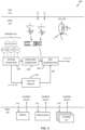
- FIG. 2 schematically illustrates functionality 200 for controlling a left wheel 270 and a right wheel 280 of a driven axle 246 by some example motion support devices (MSDs), here comprising friction brakes 255, 265 (such as disc brakes or drum brakes) and a propulsion device 240 such as an electric machine (EM) or a combustion engine (CE).
- MMDs motion support devices
- the friction brakes 255, 265 and the propulsion device 240 are examples of wheel torque generating devices, which may also be referred to as actuators and which can be controlled by one or more motion support device control units 250, 260.
- the service brakes SB1, SB2 are assumed to be controlled by respective wheel end module (WEM) controllers 250, 260, while the propulsion device 240 comprises an integrated control unit not shown in Figure 2 .
- WEM wheel end module
- the propulsion device 240 is connected to the driven axle 246 via a differential drive arrangement 245.
- This differential drive arrangement may, e.g., be an open differential which distributes torque evenly over the two wheels.
- the drive shaft speed ⁇ 0 is the average of the wheel axle speeds ⁇ 1 , ⁇ 2 (disregarding any gear ratios in-between). If one of the wheels 270, 280 suddenly experiences reduced friction, or a reduction in normal force F z acting on the wheel, then the wheel speed of that wheel increases while the speed of the other wheel decreases. This often means that overall propulsion force decreases, since neither of the wheels are operating in its desired operating point with respect to wheel speed (one is spinning too fast, while the other is rotating at a wheel speed below the optimal point).
- Each wheel 270, 280 is associated with a wheel speed sensor 275, 285, which continuously determines the current rotational velocity ⁇ 1 , ⁇ 2 of the respective wheel. There is also a sensor which determines the drive shaft rotation speed ⁇ 0 .
- the drive shaft speed sensor may be integrated with an electric machine, or arranged separately from the propulsion unit 240 in connection to the shaft 241, e.g., in the form of a Hall sensor or the like.
- This wheel speed and shaft speed information 276, 286 is fed back to the different control units, such as the control unit of the EM/CE, and the control unit of the friction brakes 250, 260.
- the wheel speed and shaft speed data may also be fed back to the VMM module 220.
- a control unit or module having access to vehicle velocity (optionally translated into a velocity in the coordinate system of a given wheel), and wheel speed data, may determine wheel slip very accurately, and with fast update rate. This allows the different actuators to perform very fast and accurate slip control, fast enough to respond in case the vehicle suddenly experiences change in friction conditions on one or both wheels 270, 280 or the driven axle 246.
- Propulsion of a heavy-duty vehicle like the vehicle 100 has traditionally been handled using control loops based on torque requests from the control unit 130 to the various actuators.
- the torque-based control loops of a heavy-duty vehicle are normally associated with time constants on the order of 10 ms or so. This means that there is considerable delay from the configuration of a given torque until the feedback from the vehicle motion sensors are fed back to the control unit that generated the request. In some scenarios this time constant reduces overall vehicle control bandwidth to a point where the startability and overall vehicle motion management of the heavy-duty vehicle may be negatively affected, especially when road friction is uneven at the different wheels.
- a traffic situation management (TSM) function 210 plans driving operations with a time horizon of, e.g., 1-10 seconds or so. This time frame corresponds to, e.g., the time it takes for the vehicle 100 to negotiate a curve.
- the vehicle maneuvers, planned and executed by the TSM can be associated with acceleration profiles and curvature profiles which describe a desired vehicle velocity and turning for a given maneuver.
- the TSM continuously requests the desired acceleration profiles a req and curvature profiles c req from the VMM function 220 which performs force allocation to meet the requests from the TSM in a safe and robust manner, based at least in part based on capability reports (CAP) received from the various MSD control units.
- CAP capability reports
- Desired acceleration profiles and curvature profiles may optionally be determined based on input from a driver via a human machine interface of the heavy-duty vehicle via normal control input devices such as a steering wheel, accelerator pedal and brake pedal, although the techniques disclosed herein are just as applicable with autonomous or semi-autonomous vehicles.
- the exact methods used for determining the acceleration profiles and curvature profiles is not within scope of the present invention and will therefore not be discussed in more detail herein.
- Both the friction brakes 255, 265 and the propulsion device 240 interact with the road surface via the tyres on the wheels 270, 280.
- the tyre properties and behavioral characteristics have an impact on how the different control actions by the friction brakes and the propulsion device generate vehicle motion.
- a tyre is subject to a longitudinal force F x , a lateral force F y , and a normal force F z .
- the normal force F z is key to determining some important vehicle properties. For instance, the normal force to a large extent determines the achievable longitudinal tyre force F x by the wheel since, normally, F x ⁇ ⁇ F z , where ⁇ is a friction coefficient associated with a road friction condition. This and other important relationships related to wheel force and wheel slip is described in, e.g., " Tyre and vehicle dynamics", Elsevier Ltd. 2012, ISBN 978-0-08-097016-5, by Hans Pacejka.
- a software-based tyre model is optionally comprised in the system.
- This tyre model provides information about the tyre currently mounted on the wheel, its properties, and behavioral characteristics.
- the tyre model may, as mentioned above, be implemented as a look-up table or other type of function.
- the tyre model is parameterized, i.e., defined, by one or more tyre parameters. This means that the function itself varies in dependence of the tyre properties.
- the tyre model can be used to model various relationships, such as a relationship or mapping between wheel slip and generated wheel force, and/or a mapping between tyre wear rate and vehicle state such as tyre normal load, vehicle speed, and wheel slip. It is appreciated that the present invention is not limited to any particular form of tyre model structure. Rather, it is appreciated that many different types of mathematical and/or experimentally based functions and mappings can be used as the tyre model.
- the tyre model can be used to define a relationship between longitudinal tyre force F x for a given wheel and an equivalent longitudinal wheel slip for the wheel.
- Longitudinal wheel slip ⁇ x relates to a difference between wheel rotational velocity and speed over ground and will be discussed in more detail below.
- Wheel, axle or shaft rotation speed ⁇ is a rotational speed given in units of, e.g., rotations per minute (rpm) or angular velocity in terms radians/second (rad/sec) or degrees/second (deg/sec).
- rpm rotations per minute
- rad/sec angular velocity in terms radians/second
- deg/sec degrees/second
- R is an effective wheel radius in meters
- ⁇ x is the angular velocity of the wheel
- v x is the longitudinal speed of the wheel (in the coordinate system of the wheel).
- A is bounded between -1 and 1 and quantifies how much the wheel is slipping with respect to the road surface.
- Wheel slip is, in essence, a speed difference measured between the wheel and the vehicle.
- the herein disclosed techniques can be adapted for use with any type of wheel slip definition. It is also appreciated that a wheel slip value is equivalent to a wheel speed value given a velocity of the wheel over the surface, in
- the present invention relates primarily to longitudinal wheel slip, although it is appreciated that the two are connected, mainly since the ability to generate lateral wheel force depends strongly on the longitudinal wheel slip.
- a shaft slip ⁇ , ⁇ K ⁇ 0 ⁇ v x max K ⁇ 0 v x
- the shaft slip is a measure of the difference between the rotational speed of the drive shaft 241 compared o the speed of the vehicle over ground, accounting for factors such as gear ratios, wheel diameters, and the like.
- a positive shaft slip means that at least some positive longitudinal force is being generated. In order for a wheel (or tyre) to produce a wheel force, slip must occur.
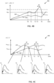
- FIG. 3 shows a graph 300 illustrating an example of achievable longitudinal tyre forces F x1 , F x2 , for the two wheels of an open differential driven axle, as function of wheel slip.
- the longitudinal tyre force shows an almost linearly increasing part 310 for small wheel slips, followed by a part 320 with more non-linear behavior for larger wheel slips. It is desirable to maintain vehicle operation in the linear region 310, where the obtainable longitudinal force in response to an applied brake or propulsion command is easier to predict.
- the product of road friction coefficient and normal force is larger for the left wheel 270 compared to the right wheel 280, i.e., the peak force ⁇ 1 F z 1 , which can be supported by the left wheel 270 is much larger than the peak force supported by the right wheel 280 ⁇ 2 F z 2 .
- the two wheel speeds ⁇ 1 , ⁇ 2 are likely to differ by variable amounts.
- the shaft slip value ⁇ 01 This relatively low shaft slip of about 0.02 is well within the linear operating range 310 for both tyres, and the wheel slips 330 caused by the shaft slip ⁇ 01 are therefore similar.
- the right wheel slip 350 will pass over its peak force point, while the left wheel slip 340 still has not reached full longitudinal force potential.
- the applied force on the shaft cannot be increased much beyond this point since it will merely increase the wheel slip of the right wheel and start to reduce the wheel slip of the left wheel (and the generated longitudinal force).
- a shaft slip ⁇ 03 is configured, then the force generated by both wheels has decreased compared to the shaft slip ⁇ 02 , since the wheel slip 360 of the left wheel is severely sub-optimal, and so is the wheel slip 370 of the right wheel.
- the right wheel 280 is about to spin out of control.
- the proposed control methods are able to quickly respond to a change in traction conditions, and prevent the vehicle from coming to a stand-still in, e.g., a hill, from which it could be very difficult to start again.
- the herein disclosed techniques present a valuable complement to the traditional traction control systems, and should not be seen as an alternative to traction control using friction brakes to transfer torque from one side to the other of a differential drive arrangement.
- the wheel speeds are monitored in order to see how wheel speed develops in response to changes in configured shaft slip.
- the wheel speed difference is monitored, and a large wheel speed difference is taken as indication that the peak shaft slip value has been exceeded.
- the correlation between a change in shaft slip and a change in wheel speeds is used.
- the two principles of estimation can be used in parallel in order to increase robustness.
- the two approaches to estimating the peak shaft slip value can also be used together, e.g., by weighting the two estimates together into a joint estimate.
- a traction control system can be triggered by a fast increase in the shaft slip limit, or shaft slip setting. If there is a difference in normal force or friction coefficient, then a large axle slip setting will cause a large wheel speed difference, which is likely to trigger traction control intervention.
- the flow chart in Figure 8A summarizes the proposed control methods.
- a method for controlling propulsion of a heavy-duty vehicle 100, 110, 120 where the heavy-duty vehicle 100, 110, 120 comprises a drive shaft 241 connected to a differential drive arrangement 245 arranged to evenly distribute torque between a left wheel 270 and a right wheel 280 of a driven axle 246.
- the method comprises configuring S1 a nominal shaft slip ⁇ 0 of the drive shaft 241 in dependence of a desired longitudinal wheel force F x to be generated by the driven axle 246.
- a shaft slip ⁇ is indicative of a difference between a current vehicle velocity v x and a vehicle velocity corresponding to the rotation speed ⁇ 0 of the drive shaft 241, as discussed above.
- the relationship between shaft slip ⁇ and longitudinal wheel force F x may be given by an inverse tyre model 300, such as that discussed in connection to Figure 3 , and the method may comprise initially obtaining S0 this inverse tyre model.
- the tyre model may, e.g., be configured at the factory, or updated continuously in dependence of vehicle type and overall condition. As mentioned above, the tyres play an important part in the realization of the tyre model, hence, a current state of the tyres may be accounted for when determining the tyre model.
- the tyre model may be obtained from the remote server 150, in response to uploading a current vehicle state.
- the vehicle may gather data about, e.g., current load, tyre state, an other vehicle parameters and send this to the remote server 150.
- the remote server 150 may then process the data and determine an inverse tyre model that accurately describes the current relationship between wheel or drive axle slip and generated longitudinal force. This processing may also be performed locally, by the ECU 130 or by the ECU 140.
- an advantage of performing the processing by the server 150 is that the data from other vehicles can also be used in constructing the tyre model, leading to a more accurate model.
- one or both ECUs 130, 140 are configured to feed wheel speed difference data to the remote server 150 via the wireless link. This allows the remote server to maintain a map of split- ⁇ locations, where a vehicle risks experiencing sub-optimal traction. The remote server 150 may then send out warning to other vehicles approaching such locations. A vehicle approaching a location where another vehicle has experienced sub-optimal traction may, e.g., adjust speed and avoid stopping in an uphill slope.
- the method also comprises obtaining S2 a rotation speed ⁇ 1 of the left wheel and a rotation speed ⁇ 2 of the right wheel, as function of a current shaft slip ⁇ of the driven axle 246.
- the wheel speeds may be obtained from wheel speed sensors 275, 285 as separate values. However, some aspects of the herein disclosed methods only require wheel speed difference.
- the data from the sensors 275, 285 may be pre-processed, perhaps by filtering to suppress measurement noise.
- the wheel speed data or the wheel speed difference data is time aligned with the current axle slip, such that at each point in time, there is a possibility to investigate which wheel speeds that were generated by a given current axle slip.
- control unit performing the method may detect, e.g., an increase in wheel speed difference and can then respond by reducing the drive shaft slip in order to maintain traction.
- This response time can be made very short, especially if the methods are being performed at the MSD layer 230, close to the actuators and to the wheels.
- the method comprises estimating S3 a peak shaft slip value ⁇ max associated with an open differential peak longitudinal force F x,max of the driven axle 246, based on the current shaft slip ⁇ and on the corresponding obtained speeds ⁇ 1 , ⁇ 2 of the left and right wheels.
- ⁇ max a peak shaft slip value associated with an open differential peak longitudinal force F x,max of the driven axle 246, based on the current shaft slip ⁇ and on the corresponding obtained speeds ⁇ 1 , ⁇ 2 of the left and right wheels.
- the method also comprises controlling S4 propulsion of the heavy-duty vehicle unit 100, 110, 120 by setting the current shaft slip ⁇ of the drive shaft 241 based on the configured nominal shaft slip ⁇ 0 adjusted in dependence of the estimated peak shaft slip value ⁇ max .
- the method comprises controlling S41 the shaft slip ⁇ of the drive shaft 241 by reducing the nominal shaft slip ⁇ 0 of the drive shaft 241 to a value below the peak shaft slip value ⁇ max in case the nominal shaft slip ⁇ 0 exceeds the peak shaft slip ⁇ max .
- This is akin to using the peak shaft slip as a slip limit which is no to be exceeded. This essentially means that a dynamic shaft slip limit is implemented, which will be adjusted very rapidly in response to changing friction conditions.
- the nominal shaft slip is used for controlling drive shaft speed as long as the nominal shaft slip is below the peak shaft slip ⁇ max .
- the methods can also be used with advantage to maximize tractive force, e.g., when launching a heavy-duty vehicle from stand-still or from a low speed.
- the method may comprise controlling S42 the shaft slip ⁇ of the drive shaft 241 to be equal to the peak shaft slip value ⁇ max , i.e., the peak shaft slip value is used as the nominal shaft slip.
- the peak shaft slip value ⁇ max can, as mentioned above, be estimated S31 as a shaft slip value where a magnitude of a difference between the speed ⁇ 1 of the left wheel and the speed ⁇ 2 of the right wheel crosses a pre-configured first threshold Th1.
- Th1 a pre-configured first threshold
- the curve 410 represents example wheel speed difference while the curve 420 represents corresponding example configured shaft slip.
- the vehicle is accelerated, perhaps from stand-still.
- the shaft slip is increased as some rate.
- the wheel speeds start to diverge, perhaps due to variation in friction at the two wheels, or different normal loads.
- the two wheels may also have differently work tyres.
- the wheel speed difference breaches a pre-determined first threshold Th1.
- Th1 the peak shaft slip value
- the shaft slip is immediately reduced.
- the reduction in shaft slip has brought the wheel slip difference back below the first threshold Th1, which means that the shaft slip can again be increased carefully.
- the first threshold is once again breached, whereupon the shaft slip is again reduced. This periodic behavior is then maintained, and the configured shaft slip will fluctuate about the peak shaft slip value.
- the obtained speed ⁇ 1 of the left wheel and the obtained speed ⁇ 2 of the right wheel is adjusted S33 based on a vehicle path curvature c req and/or on a vehicle steering angle ⁇ .
- the adjustment may be based on a model of the vehicle, which may simply be a look-up table with adjustment values listed as function of vehicle steering angle.
- aspects of the herein disclosed methods also comprise triggering S5 a service brake traction control intervention procedure in case the magnitude of the difference between the speed ⁇ 1 of the left wheel and the speed ⁇ 2 of the right wheel exceeds a pre-determined second threshold Th2.
- Th2 a pre-determined second threshold
- the wheel speed difference is shown as curve 440 and the shaft slip is shown as curve 450.
- the wheel speed difference breaches the second threshold Th2, where the traction control system kicks in, albeit after a delay d1. This activation generates a strong reduction in wheel speed difference.
- the shaft slip control is inactivated, since now additional shaft slip can be applied.
- the peak shaft slip value ⁇ max can also be estimated S32 based on correlating a change in shaft slip with a corresponding change in wheel speed of the slowest spinning wheel out of the left wheel 270 and the right wheel 280.
- the peak shaft slip value ⁇ max is then estimated as a shaft slip value where the correlation between shaft speed change and wheel speed change turns from positive to negative.
- both approaches to estimating the peak shaft slip value can be used jointly, and the results merged, possibly after weighting.
- the graph 460 in Figure 4C shows an example operation of the second approach.
- the curve 470 illustrates example wheel speed of the slower spinning wheel out of the left wheel 270 and the right wheel 280.
- the curve 480 illustrates the current shaft slip of the drive shaft 241.
- the vehicle is initially accelerated, and the shaft slip is therefore increased.
- This increase in shaft slip causes an increase in the wheel speed of the slower spinning wheel.
- the correlation between change in shaft slip and change in wheel speed is positive at first, i.e., an increase in shaft slip results in an increase in wheel speed, and a decrease in shaft slip results in a corresponding decrease in wheel speed.
- correlation between shaft slip and wheel slip can also be used in the correlation analysis.
- the correlation between shaft speed change and wheel speed change turns from positive to negative, i.e., the wheel speed starts to decrease despite the shaft slip still increasing. This behavior, as discussed above, indicates that the other wheel has passed its peak, and that the increase in wheel speed of the faster spinning wheel results in a decrease in wheel speed of the slower spinning wheel.
- the peak shaft slip value can be estimated as the shaft slip value which maximizes the smaller of the obtained speed of the left wheel and the obtained speed of the right wheel.
- the control then comprises adjusting the shaft slip and monitoring what happens with the wheel speeds as the shaft slip is changed. For instance, if when shaft slip is increased and the lowest speed wheel's slip increases and the high speed wheel's slip increases then continue to increase the shaft slip since this will generate more traction force, however, if shaft slip is increased and the low speed wheel decreases slip, then the shaft slip should be decreased since further increase in shaft slip will lead to reduced traction force. If shaft slip is instead decreased and both wheels decrease in slip, then shaft slip should be increased for more traction force.
- control comprises applying a probing shaft slip control pattern involving both increase and decrease in shaft slip, in order to determine the gradient of the longitudinal force with respect the shaft slip.
- a probing shaft slip control pattern involving both increase and decrease in shaft slip, in order to determine the gradient of the longitudinal force with respect the shaft slip.
- This probing pattern of the shaft slip may be a sinusoidal or sawtooth pattern comprising increases and decreases in wheel slip according to a pre-determined pattern.
- the probing pattern may be applied in response to detecting a divergence in wheel slip.
- the probing pattern may also be applied regularly during vehicle launch.
- the magnitude of w determines the bandwidth constraint. A large w allows for rapid convergence, and vice versa.
- the magnitude of w may be selected as a function of the rate of change in the wheel speed difference, i.e., if ⁇ 1 k ⁇ ⁇ 2 k ⁇ ⁇ 1 k + 1 ⁇ ⁇ 2 k + 1 then wheel speed difference is increasing and w is then selected larger compared to the case where ⁇ 1 k ⁇ ⁇ 2 k > ⁇ 1 k + 1 ⁇ ⁇ 2 k + 1
- the drive shaft slip is controlled S43 according to a bandwidth constraint, where the bandwidth constraint is smaller for a decreasing controlled shaft slip compared to an increasing drive shaft slip ⁇ .
- Figure 8B illustrates a method for launching a heavy-duty vehicle 100 from stand-still, where the heavy-duty vehicle 100, 110, 120 comprises a drive shaft 241 connected to a differential drive arrangement 245 arranged to evenly distribute torque between a left wheel 270 and a right wheel 280 of a driven axle 246.
- the method comprises increasing Sb1 a rotation speed ⁇ 0 of the drive shaft 241 at a pre-determined rate of increase, obtaining Sb2 a rotation speed ⁇ 1 of the left wheel and a rotation speed ⁇ 2 of the right wheel, as function of a current shaft slip ⁇ of the driven axle 246, wherein a shaft slip is indicative of a difference between a current vehicle velocity v x and a vehicle velocity corresponding to the rotation speed ⁇ 0 of the drive shaft 241, and estimating Sb3 a peak shaft slip value ⁇ max associated with an open differential peak longitudinal force F x,max of the driven axle 246, based on the current shaft slip ⁇ and on the corresponding obtained speeds ⁇ 1 , ⁇ 2 of the left and right wheels, and maintaining Sb4 rotation speed ⁇ 0 of the drive shaft 241 to generate a shaft slip ⁇ equal to the peak shaft slip value ⁇ max .
- FIG 5 shows an example of a vehicle control stack 500 comprising the above-mentioned TSM 210 and VMM 220 functions, where the proposed technique may be implemented with advantage.
- Sensors 510 arranged to provide data about the vehicle environment provides input to the overall control stack 500, and a connection to remote processing resources, such as cloud-based processing resources like the remote server 150 in Figure 1 are also optionally comprised in the control stack.
- remote processing resources such as cloud-based processing resources like the remote server 150 in Figure 1 are also optionally comprised in the control stack.
- the VMM function 210 operates with a time horizon of about 0,1-1,5 seconds or so, and continuously transforms the acceleration profiles a req and curvature profiles c req into control commands for controlling vehicle motion functions, actuated by the different MSDs of the vehicle 100 which report back capabilities to the VMM, which in turn are used as constraints in the vehicle control.
- the accuracy of this control is improved by means of the advanced tyre models 380 discussed herein.
- the VMM function 210 performs vehicle state or motion estimation 520, i.e., the VMM function 210 continuously determines a vehicle state s (often a vector variable) comprising positions, speeds, accelerations, yaw motions, normal forces and articulation angles of the different units in the vehicle combination by monitoring vehicle state and behavior using various sensors 510 arranged on the vehicle 100, often but not always in connection to the MSDs.
- vehicle state s often a vector variable
- the result of the motion estimation 520 i.e., the estimated vehicle state s, is input to a global force generation module 530 which determines the required global forces on the vehicle units which need to be generated in order to meet the motion requests from the TSM 210.
- An MSD coordination function 540 allocates, e.g., wheel forces and coordinates other MSDs such as steering and suspension. The coordinated MSDs then together provide the desired lateral Fy and longitudinal Fx forces on the vehicle units, as well as the required moments Mz, to obtain the desired motion by the vehicle combination 100.
- the MSD coordination function 540 may output any of wheel slips ⁇ i , wheel rotation speeds ⁇ , and/or steering angles ⁇ l to the different MSDs.
- a peak-slip detector module 550 is arranged to monitor wheel speeds and to perform some or all of the different methods discussed herein.
- the peak-slip detector may also be arranged to intervene in case the wheel speeds diverge and or start to exhibit inverse proportional relationship with the shaft slip. When this happens, a control signal can be sent to the MSD coordination module 540 which will reduce the configured shaft slip in response to the control signal 560.
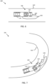
- Figure 6 illustrates an example split- ⁇ scenario 600, where a heavy-duty vehicle 100 drives straight on a road 610 in a forward direction with vehicle velocity v x 620.
- a region of low friction 630 is encountered by the right wheels of the vehicle 100.
- the right-hand side wheels may start to spin faster than the left-hand side wheels, giving rise to the sub-optimal operating points illustrated in Figure 3 , i.e., where one wheel is to the right of the nominal desired slip and the other wheel is to the left of the desired operating point.
- the herein proposed techniques will then quickly step in and reduce the shaft slip down to a level where the speed of the spinning wheel is reduced, thus improving overall traction very fast, much faster than would have been possible using legacy traction control system based on slow torque-based control of service brakes.
- the methods proposed herein also act in a more continuous manner, and may be configured to activate already at small wheel speed differences. Traction control system often require larger wheel speed differences before they kick in, due to robustness reasons.
- FIG. 7 illustrates another example scenario 700, but now the vehicle is cornering, i.e., follows a path associated with a curvature.
- the curvature itself gives rise to a difference in wheel speeds.
- This wheel speed difference is preferably accounted for by the method, i.e., such wheel speed differences due to planned curve taking will optionally not result in a modified shaft slip.
- the vehicle 100 encounters a region 630 of low friction, which causes the wheel speed difference to deviate from that expected from the curvature, which may cause a reduction in shaft slip request to the propulsion device.
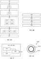
- FIG. 9 schematically illustrates, in terms of a number of functional units, the components of a control unit 900 according to embodiments of the discussions herein, such as any of the VUCs 130, 140.
- This control unit 900 may be comprised in the articulated vehicle 100.
- Processing circuitry 910 is provided using any combination of one or more of a suitable central processing unit CPU, multiprocessor, microcontroller, digital signal processor DSP, etc., capable of executing software instructions stored in a computer program product, e.g. in the form of a storage medium 930.
- the processing circuitry 910 may further be provided as at least one application specific integrated circuit ASIC, or field programmable gate array FPGA.
- the processing circuitry 910 is configured to cause the control unit 900 to perform a set of operations, or steps, such as the methods discussed in connection to Figure 8A and Figure 8B .
- the storage medium 930 may store the set of operations
- the processing circuitry 910 may be configured to retrieve the set of operations from the storage medium 930 to cause the control unit 700 to perform the set of operations.
- the set of operations may be provided as a set of executable instructions.
- the processing circuitry 910 is thereby arranged to execute methods as herein disclosed.
- control unit 130 arranged to control propulsion of a heavy-duty vehicle 100, where the heavy-duty vehicle 100 comprises a differential drive arrangement 245 arranged in connection to a driven axle 246 with a left wheel 270 and a right wheel 280.
- the storage medium 930 may also comprise persistent storage, which, for example, can be any single one or combination of magnetic memory, optical memory, solid state memory or even remotely mounted memory.
- the control unit 700 may further comprise an interface 920 for communications with at least one external device.
- the interface 920 may comprise one or more transmitters and receivers, comprising analogue and digital components and a suitable number of ports for wireline or wireless communication.
- the processing circuitry 910 controls the general operation of the control unit 700, e.g., by sending data and control signals to the interface 920 and the storage medium 930, by receiving data and reports from the interface 920, and by retrieving data and instructions from the storage medium 930.
- Other components, as well as the related functionality, of the control node are omitted in order not to obscure the concepts presented herein.
- Figure 10 illustrates a computer readable medium 1010 carrying a computer program comprising program code means 1020 for performing the methods illustrated in Figures 8A-B , when said program product is run on a computer.
- the computer readable medium and the code means may together form a computer program product 1000.
Landscapes
- Engineering & Computer Science (AREA)
- Transportation (AREA)
- Mechanical Engineering (AREA)
- Automation & Control Theory (AREA)
- Combustion & Propulsion (AREA)
- Chemical & Material Sciences (AREA)
- Physics & Mathematics (AREA)
- Mathematical Physics (AREA)
- Software Systems (AREA)
- Theoretical Computer Science (AREA)
- General Physics & Mathematics (AREA)
- General Engineering & Computer Science (AREA)
- Regulating Braking Force (AREA)
- Control Of Driving Devices And Active Controlling Of Vehicle (AREA)
Priority Applications (5)
| Application Number | Priority Date | Filing Date | Title |
|---|---|---|---|
| EP21181576.6A EP4108529B1 (en) | 2021-06-24 | 2021-06-24 | A method for controlling propulsion of a heavy-duty vehicle |
| JP2022090797A JP2023004904A (ja) | 2021-06-24 | 2022-06-03 | 大型車の推進を制御するための方法 |
| CN202210629083.5A CN115593389A (zh) | 2021-06-24 | 2022-06-06 | 用于控制重型车辆的推进的方法 |
| KR1020220069954A KR20230000958A (ko) | 2021-06-24 | 2022-06-09 | 대형 차량의 추진력 제어 방법 |
| US17/806,199 US12221088B2 (en) | 2021-06-24 | 2022-06-09 | Method for controlling propulsion of a heavy-duty vehicle |
Applications Claiming Priority (1)
| Application Number | Priority Date | Filing Date | Title |
|---|---|---|---|
| EP21181576.6A EP4108529B1 (en) | 2021-06-24 | 2021-06-24 | A method for controlling propulsion of a heavy-duty vehicle |
Publications (3)
| Publication Number | Publication Date |
|---|---|
| EP4108529A1 EP4108529A1 (en) | 2022-12-28 |
| EP4108529C0 EP4108529C0 (en) | 2024-10-30 |
| EP4108529B1 true EP4108529B1 (en) | 2024-10-30 |
Family
ID=76999574
Family Applications (1)
| Application Number | Title | Priority Date | Filing Date |
|---|---|---|---|
| EP21181576.6A Active EP4108529B1 (en) | 2021-06-24 | 2021-06-24 | A method for controlling propulsion of a heavy-duty vehicle |
Country Status (5)
| Country | Link |
|---|---|
| US (1) | US12221088B2 (enExample) |
| EP (1) | EP4108529B1 (enExample) |
| JP (1) | JP2023004904A (enExample) |
| KR (1) | KR20230000958A (enExample) |
| CN (1) | CN115593389A (enExample) |
Families Citing this family (7)
| Publication number | Priority date | Publication date | Assignee | Title |
|---|---|---|---|---|
| IT202300013944A1 (it) * | 2023-07-04 | 2025-01-04 | Stellantis Europe Spa | Procedimento per calcolare un trasferimento di coppia preventivo fra ruote di un medesimo assale in condizioni di bassa velocità |
| CN119428709A (zh) * | 2023-07-28 | 2025-02-14 | 比亚迪股份有限公司 | 一种用于四轮独立驱动车辆的车速估算方法、系统、计算机可读存储介质、电子设备及车辆 |
| US12459520B2 (en) * | 2023-08-28 | 2025-11-04 | Fca Us Llc | Control of vehicle on loose surfaces |
| WO2025103567A1 (en) * | 2023-11-13 | 2025-05-22 | Volvo Truck Corporation | Road slope based wheel slip control for open differentials |
| WO2025103566A1 (en) * | 2023-11-13 | 2025-05-22 | Volvo Truck Corporation | Road slope based actuator control for open differentials |
| CN117719361B (zh) * | 2023-12-19 | 2024-05-24 | 湖南铁华精斧汽车集团股份有限公司 | 一种新能源半挂车驱动控制方法及系统 |
| US20250333063A1 (en) * | 2024-04-26 | 2025-10-30 | Fca Us Llc | Driving condition determination and communication system with connected vehicles |
Family Cites Families (16)
| Publication number | Priority date | Publication date | Assignee | Title |
|---|---|---|---|---|
| DE19849322B4 (de) * | 1998-10-26 | 2014-09-11 | Robert Bosch Gmbh | Verfahren und Vorrichtung zur Schätzung des maximal absetzbaren Antriebsmoments bei einem Kraftfahrzeug |
| US6542806B1 (en) * | 2001-05-24 | 2003-04-01 | Brunswick Corporation | Optimal tractive force control method for ground vehicles |
| DE10234606B4 (de) * | 2002-07-30 | 2021-12-16 | Robert Bosch Gmbh | Verfahren und Vorrichtung zur Stabilisierung eines Fahrzeugs |
| JP2004090886A (ja) | 2002-09-04 | 2004-03-25 | Advics:Kk | 車両のトラクション制御装置 |
| AU2003205686A1 (en) * | 2003-01-27 | 2004-08-23 | Nira Dynamics Ab | Method, system and computer program product for wheel slip control |
| DE102006007740B4 (de) * | 2006-02-20 | 2014-01-02 | Knorr-Bremse Systeme für Nutzfahrzeuge GmbH | Verfahren und Vorrichtung zur Regelung des Antriebsschlupfes angetriebener Räder eines Fahrzeugs mit der Motordrehzahl als Stellgröße |
| GB201308807D0 (en) * | 2013-05-16 | 2013-07-03 | Jaguar Land Rover Ltd | Vehicle traction control |
| JP6236672B2 (ja) * | 2013-09-26 | 2017-11-29 | 日立オートモティブシステムズ株式会社 | 電動車両の制御装置 |
| WO2016095825A1 (zh) * | 2014-12-16 | 2016-06-23 | 比亚迪股份有限公司 | 电动车辆、电动车辆的主动安全控制系统及其控制方法 |
| JP6219883B2 (ja) | 2015-05-22 | 2017-10-25 | 株式会社アドヴィックス | 車両用制御装置 |
| US10974705B2 (en) * | 2016-06-15 | 2021-04-13 | Volvo Truck Corporation | Wheel controller for a vehicle |
| DE102017000547A1 (de) * | 2017-01-21 | 2018-07-26 | Wabco Gmbh | Verfahren zur Verzögerung eines Anhängefahrzeugs, Radmodul zur Durchführung des Verfahrens sowie Fahrzeugkombination mit einem solchen Radmodul |
| GB2560590B (en) * | 2017-03-17 | 2020-02-12 | Jaguar Land Rover Ltd | Improvements in traction control to aid launch in friction-limited terrains |
| EP3569436B1 (en) * | 2018-05-17 | 2022-05-11 | Bayerische Motoren Werke Aktiengesellschaft | Traction control system |
| SE542777C2 (en) * | 2018-07-03 | 2020-07-07 | Scania Cv Ab | A method for controlling a powertrain, a control arrangement for controlling a powertrain, a powertrain, a vehicle, a computer program and a computer-readable medium. |
| KR102791587B1 (ko) * | 2020-10-07 | 2025-04-03 | 현대자동차주식회사 | 차량의 휠 슬립 제어 방법 |
-
2021
- 2021-06-24 EP EP21181576.6A patent/EP4108529B1/en active Active
-
2022
- 2022-06-03 JP JP2022090797A patent/JP2023004904A/ja active Pending
- 2022-06-06 CN CN202210629083.5A patent/CN115593389A/zh active Pending
- 2022-06-09 KR KR1020220069954A patent/KR20230000958A/ko active Pending
- 2022-06-09 US US17/806,199 patent/US12221088B2/en active Active
Also Published As
| Publication number | Publication date |
|---|---|
| US20220410853A1 (en) | 2022-12-29 |
| CN115593389A (zh) | 2023-01-13 |
| EP4108529C0 (en) | 2024-10-30 |
| KR20230000958A (ko) | 2023-01-03 |
| JP2023004904A (ja) | 2023-01-17 |
| EP4108529A1 (en) | 2022-12-28 |
| US12221088B2 (en) | 2025-02-11 |
Similar Documents
| Publication | Publication Date | Title |
|---|---|---|
| EP4108529B1 (en) | A method for controlling propulsion of a heavy-duty vehicle | |
| EP3851346B1 (en) | An inverse tyre model for advanced vehicle motion management | |
| EP4090548B1 (en) | A differential electrical drive arrangement for heavy duty vehicles | |
| EP4219252B1 (en) | A method for controlling a heavy-duty vehicle | |
| US12391260B2 (en) | Redundant vehicle control systems based on tire sensors—load estimation | |
| JP2023035900A (ja) | 動的に構成されたサイドスリップ限界に基づく車両制御 | |
| EP4330097B1 (en) | Vehicle control based on dynamically configured longitudinal wheel slip limits | |
| JP2024541857A (ja) | 大型車両向け逆タイヤモデルブースト機能 | |
| US20220063575A1 (en) | Vehicle motion management with a redundant wheel control safety net function | |
| US12030477B2 (en) | Redundant vehicle control systems based on tire sensors | |
| US12434676B2 (en) | Wheel slip-based motion control for heavy-duty vehicles | |
| EP4355602B1 (en) | A method for controlling propulsion of a heavy-duty vehicle | |
| US20250050851A1 (en) | Robust actuator control methods for heavy-duty vehicle motion management | |
| US20250058766A1 (en) | Predictive heavy-duty vehicle motion management based on environment sensing | |
| JP2024541380A (ja) | 大型車両の加速及び減速のための車輪スリップベースの制御 | |
| JP2025504885A (ja) | 大型車両運動支援装置の能力フィードバック |
Legal Events
| Date | Code | Title | Description |
|---|---|---|---|
| PUAI | Public reference made under article 153(3) epc to a published international application that has entered the european phase |
Free format text: ORIGINAL CODE: 0009012 |
|
| STAA | Information on the status of an ep patent application or granted ep patent |
Free format text: STATUS: THE APPLICATION HAS BEEN PUBLISHED |
|
| AK | Designated contracting states |
Kind code of ref document: A1 Designated state(s): AL AT BE BG CH CY CZ DE DK EE ES FI FR GB GR HR HU IE IS IT LI LT LU LV MC MK MT NL NO PL PT RO RS SE SI SK SM TR |
|
| STAA | Information on the status of an ep patent application or granted ep patent |
Free format text: STATUS: REQUEST FOR EXAMINATION WAS MADE |
|
| 17P | Request for examination filed |
Effective date: 20230411 |
|
| RBV | Designated contracting states (corrected) |
Designated state(s): AL AT BE BG CH CY CZ DE DK EE ES FI FR GB GR HR HU IE IS IT LI LT LU LV MC MK MT NL NO PL PT RO RS SE SI SK SM TR |
|
| GRAP | Despatch of communication of intention to grant a patent |
Free format text: ORIGINAL CODE: EPIDOSNIGR1 |
|
| STAA | Information on the status of an ep patent application or granted ep patent |
Free format text: STATUS: GRANT OF PATENT IS INTENDED |
|
| RIC1 | Information provided on ipc code assigned before grant |
Ipc: B60W 30/18 20120101ALI20240606BHEP Ipc: B60T 8/175 20060101AFI20240606BHEP |
|
| INTG | Intention to grant announced |
Effective date: 20240627 |
|
| GRAS | Grant fee paid |
Free format text: ORIGINAL CODE: EPIDOSNIGR3 |
|
| GRAA | (expected) grant |
Free format text: ORIGINAL CODE: 0009210 |
|
| STAA | Information on the status of an ep patent application or granted ep patent |
Free format text: STATUS: THE PATENT HAS BEEN GRANTED |
|
| AK | Designated contracting states |
Kind code of ref document: B1 Designated state(s): AL AT BE BG CH CY CZ DE DK EE ES FI FR GB GR HR HU IE IS IT LI LT LU LV MC MK MT NL NO PL PT RO RS SE SI SK SM TR |
|
| REG | Reference to a national code |
Ref country code: GB Ref legal event code: FG4D |
|
| REG | Reference to a national code |
Ref country code: CH Ref legal event code: EP |
|
| REG | Reference to a national code |
Ref country code: IE Ref legal event code: FG4D |
|
| REG | Reference to a national code |
Ref country code: DE Ref legal event code: R096 Ref document number: 602021020882 Country of ref document: DE |
|
| U01 | Request for unitary effect filed |
Effective date: 20241118 |
|
| U07 | Unitary effect registered |
Designated state(s): AT BE BG DE DK EE FI FR IT LT LU LV MT NL PT RO SE SI Effective date: 20241122 |
|
| PG25 | Lapsed in a contracting state [announced via postgrant information from national office to epo] |
Ref country code: IS Free format text: LAPSE BECAUSE OF FAILURE TO SUBMIT A TRANSLATION OF THE DESCRIPTION OR TO PAY THE FEE WITHIN THE PRESCRIBED TIME-LIMIT Effective date: 20250228 Ref country code: HR Free format text: LAPSE BECAUSE OF FAILURE TO SUBMIT A TRANSLATION OF THE DESCRIPTION OR TO PAY THE FEE WITHIN THE PRESCRIBED TIME-LIMIT Effective date: 20241030 |
|
| PG25 | Lapsed in a contracting state [announced via postgrant information from national office to epo] |
Ref country code: ES Free format text: LAPSE BECAUSE OF FAILURE TO SUBMIT A TRANSLATION OF THE DESCRIPTION OR TO PAY THE FEE WITHIN THE PRESCRIBED TIME-LIMIT Effective date: 20241030 |
|
| PG25 | Lapsed in a contracting state [announced via postgrant information from national office to epo] |
Ref country code: NO Free format text: LAPSE BECAUSE OF FAILURE TO SUBMIT A TRANSLATION OF THE DESCRIPTION OR TO PAY THE FEE WITHIN THE PRESCRIBED TIME-LIMIT Effective date: 20250130 |
|
| PG25 | Lapsed in a contracting state [announced via postgrant information from national office to epo] |
Ref country code: GR Free format text: LAPSE BECAUSE OF FAILURE TO SUBMIT A TRANSLATION OF THE DESCRIPTION OR TO PAY THE FEE WITHIN THE PRESCRIBED TIME-LIMIT Effective date: 20250131 |
|
| PG25 | Lapsed in a contracting state [announced via postgrant information from national office to epo] |
Ref country code: PL Free format text: LAPSE BECAUSE OF FAILURE TO SUBMIT A TRANSLATION OF THE DESCRIPTION OR TO PAY THE FEE WITHIN THE PRESCRIBED TIME-LIMIT Effective date: 20241030 |
|
| PG25 | Lapsed in a contracting state [announced via postgrant information from national office to epo] |
Ref country code: RS Free format text: LAPSE BECAUSE OF FAILURE TO SUBMIT A TRANSLATION OF THE DESCRIPTION OR TO PAY THE FEE WITHIN THE PRESCRIBED TIME-LIMIT Effective date: 20250130 |
|
| PG25 | Lapsed in a contracting state [announced via postgrant information from national office to epo] |
Ref country code: SM Free format text: LAPSE BECAUSE OF FAILURE TO SUBMIT A TRANSLATION OF THE DESCRIPTION OR TO PAY THE FEE WITHIN THE PRESCRIBED TIME-LIMIT Effective date: 20241030 |
|
| PG25 | Lapsed in a contracting state [announced via postgrant information from national office to epo] |
Ref country code: SK Free format text: LAPSE BECAUSE OF FAILURE TO SUBMIT A TRANSLATION OF THE DESCRIPTION OR TO PAY THE FEE WITHIN THE PRESCRIBED TIME-LIMIT Effective date: 20241030 |
|
| PG25 | Lapsed in a contracting state [announced via postgrant information from national office to epo] |
Ref country code: CZ Free format text: LAPSE BECAUSE OF FAILURE TO SUBMIT A TRANSLATION OF THE DESCRIPTION OR TO PAY THE FEE WITHIN THE PRESCRIBED TIME-LIMIT Effective date: 20241030 |
|
| U20 | Renewal fee for the european patent with unitary effect paid |
Year of fee payment: 5 Effective date: 20250624 |
|
| PLBE | No opposition filed within time limit |
Free format text: ORIGINAL CODE: 0009261 |
|
| STAA | Information on the status of an ep patent application or granted ep patent |
Free format text: STATUS: NO OPPOSITION FILED WITHIN TIME LIMIT |
|
| 26N | No opposition filed |
Effective date: 20250731 |