EP4108477A1 - Aircraft tire - Google Patents
Aircraft tire Download PDFInfo
- Publication number
- EP4108477A1 EP4108477A1 EP21756892.2A EP21756892A EP4108477A1 EP 4108477 A1 EP4108477 A1 EP 4108477A1 EP 21756892 A EP21756892 A EP 21756892A EP 4108477 A1 EP4108477 A1 EP 4108477A1
- Authority
- EP
- European Patent Office
- Prior art keywords
- antenna
- aircraft tire
- tire
- aircraft
- rfid tag
- Prior art date
- Legal status (The legal status is an assumption and is not a legal conclusion. Google has not performed a legal analysis and makes no representation as to the accuracy of the status listed.)
- Granted
Links
Images



Classifications
-
- G—PHYSICS
- G06—COMPUTING OR CALCULATING; COUNTING
- G06K—GRAPHICAL DATA READING; PRESENTATION OF DATA; RECORD CARRIERS; HANDLING RECORD CARRIERS
- G06K19/00—Record carriers for use with machines and with at least a part designed to carry digital markings
- G06K19/06—Record carriers for use with machines and with at least a part designed to carry digital markings characterised by the kind of the digital marking, e.g. shape, nature, code
- G06K19/067—Record carriers with conductive marks, printed circuits or semiconductor circuit elements, e.g. credit or identity cards also with resonating or responding marks without active components
- G06K19/07—Record carriers with conductive marks, printed circuits or semiconductor circuit elements, e.g. credit or identity cards also with resonating or responding marks without active components with integrated circuit chips
- G06K19/077—Constructional details, e.g. mounting of circuits in the carrier
- G06K19/07749—Constructional details, e.g. mounting of circuits in the carrier the record carrier being capable of non-contact communication, e.g. constructional details of the antenna of a non-contact smart card
- G06K19/07758—Constructional details, e.g. mounting of circuits in the carrier the record carrier being capable of non-contact communication, e.g. constructional details of the antenna of a non-contact smart card arrangements for adhering the record carrier to further objects or living beings, functioning as an identification tag
- G06K19/07764—Constructional details, e.g. mounting of circuits in the carrier the record carrier being capable of non-contact communication, e.g. constructional details of the antenna of a non-contact smart card arrangements for adhering the record carrier to further objects or living beings, functioning as an identification tag the adhering arrangement making the record carrier attachable to a tyre
-
- B—PERFORMING OPERATIONS; TRANSPORTING
- B60—VEHICLES IN GENERAL
- B60C—VEHICLE TYRES; TYRE INFLATION; TYRE CHANGING; CONNECTING VALVES TO INFLATABLE ELASTIC BODIES IN GENERAL; DEVICES OR ARRANGEMENTS RELATED TO TYRES
- B60C19/00—Tyre parts or constructions not otherwise provided for
-
- B—PERFORMING OPERATIONS; TRANSPORTING
- B60—VEHICLES IN GENERAL
- B60C—VEHICLE TYRES; TYRE INFLATION; TYRE CHANGING; CONNECTING VALVES TO INFLATABLE ELASTIC BODIES IN GENERAL; DEVICES OR ARRANGEMENTS RELATED TO TYRES
- B60C19/00—Tyre parts or constructions not otherwise provided for
- B60C19/003—Balancing means attached to the tyre
-
- B—PERFORMING OPERATIONS; TRANSPORTING
- B60—VEHICLES IN GENERAL
- B60C—VEHICLE TYRES; TYRE INFLATION; TYRE CHANGING; CONNECTING VALVES TO INFLATABLE ELASTIC BODIES IN GENERAL; DEVICES OR ARRANGEMENTS RELATED TO TYRES
- B60C9/00—Reinforcements or ply arrangement of pneumatic tyres
- B60C9/18—Structure or arrangement of belts or breakers, crown-reinforcing or cushioning layers
- B60C9/20—Structure or arrangement of belts or breakers, crown-reinforcing or cushioning layers built-up from rubberised plies each having all cords arranged substantially parallel
-
- B—PERFORMING OPERATIONS; TRANSPORTING
- B60—VEHICLES IN GENERAL
- B60C—VEHICLE TYRES; TYRE INFLATION; TYRE CHANGING; CONNECTING VALVES TO INFLATABLE ELASTIC BODIES IN GENERAL; DEVICES OR ARRANGEMENTS RELATED TO TYRES
- B60C11/00—Tyre tread bands; Tread patterns; Anti-skid inserts
-
- B—PERFORMING OPERATIONS; TRANSPORTING
- B60—VEHICLES IN GENERAL
- B60C—VEHICLE TYRES; TYRE INFLATION; TYRE CHANGING; CONNECTING VALVES TO INFLATABLE ELASTIC BODIES IN GENERAL; DEVICES OR ARRANGEMENTS RELATED TO TYRES
- B60C19/00—Tyre parts or constructions not otherwise provided for
- B60C2019/004—Tyre sensors other than for detecting tyre pressure
-
- B—PERFORMING OPERATIONS; TRANSPORTING
- B60—VEHICLES IN GENERAL
- B60C—VEHICLE TYRES; TYRE INFLATION; TYRE CHANGING; CONNECTING VALVES TO INFLATABLE ELASTIC BODIES IN GENERAL; DEVICES OR ARRANGEMENTS RELATED TO TYRES
- B60C2200/00—Tyres specially adapted for particular applications
- B60C2200/02—Tyres specially adapted for particular applications for aircrafts
Definitions
- the present invention relates to an aircraft tire mainly used for an airliner or the like.
- An aircraft tire is managed by attaching the RFID tag to the aircraft tire, and writing and reading information related to the tire.
- Patent Literature 1 discloses a structure of an aircraft tire in which the RFID is embedded in a crown region thereof and a dipole antenna is disposed in an axial direction.
- Patent Literature 1 U.S. Patent Application Publication No. 2011/0226401
- the above-described conventional aircraft tire may have a problem that a communication performance deteriorates due to attenuation of electromagnetic waves or the like caused by a large tire width.
- An object of the present invention is to provide an aircraft tire that improves RIFD tag communication performance even when a size is 21 inches or larger.
- an aircraft tire (T) has a pair of bead sections (100), sidewall sections (104) extending from outer side in a radial direction of the bead section, and a tread section (106) extending between the sidewall sections;
- the aircraft tire includes an RFID tag (10) having a tag main body (11) configured to store information about the aircraft tire, and an antenna (A1, A2) extended from the tag main body; wherein, in a tread surface view, the antenna is disposed such that an extending direction (D1) of the antenna is parallel to a tire width direction or intersects the tire width direction (D2) within a predetermined angle range, and the aircraft tire satisfies a relationship 0.1 ⁇ L/W ⁇ 0.2, where a width of the aircraft tire is denoted as "W” and a total length of the antenna in the extending direction of the antenna is denoted as "L”, and when a diameter of the aircraft tire is 21 inches or more.
- the communication performance of the RFID tag can be improved by satisfying the above relationship to reduce attenuation of electromagnetic waves or the like, even when the size thereof is 21 inches or more.
- FIGS. 1 to 9 An aircraft tire T according to an embodiment of one or more embodiments will be described with reference to FIGS. 1 to 9 .
- FIGS. 1 and 2 An example of a configuration of an aircraft tire T will be described with reference to FIGS. 1 and 2 .
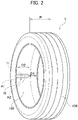
- FIG. 1 is a cross-sectional view in a tread width direction illustrating a schematic configuration of the aircraft tire T according to one or more embodiments; and FIG. 2 is a perspective view illustrating a schematic configuration of the aircraft tire T.
- the aircraft tire T includes a bead section 100 to be in contact with a wheel 150, a carcass 101 as a frame of the aircraft tire T, a plurality of belt parts 103 disposed on an outer side in a tire radial direction of the carcass 101, and a tread section 106 disposed on an outer side in the tire radial direction of the belt part 103 and configured to be in contact with a road surface.
- a sidewall section 104 extending from an outer side in a radial direction of a pair of the bead sections 100.
- a tire inner surface 102 of the aircraft tire T is provided with an RFID tag 10 including an IC chip 11 as a tag main body configured to store information (information such as serial number, size, and proper internal pressure) about the aircraft tire T and antennas A1 and A2 extended from the IC chip 11.
- information information such as serial number, size, and proper internal pressure
- the RFID tag 10 is formed by sealing the IC chip 11 and the antennas A1 and A2 within a rubber patch 12, and is attached to the tire inner surface 102 by an adhesive.
- the antennas A1 and A2 are disposed such that their extending direction D1 is parallel to a tire width direction D2 or intersects the tire width direction D2 within a predetermined angle range (For example, within 5 degrees) in a tread surface view.
- the aircraft tire satisfies a relationship 0.1 ⁇ L/W ⁇ 0.2, where a width of the aircraft tire is denoted as "W” and a total length (LI, L2) of the antennas in the extending direction D1 is "L", and when a diameter of the aircraft tire T is 21 inches or more.
- a RFID reader/writer 200 illustrated in FIG. 1 is configured to transmit and receive information to and from the RFID tag 10.
- the RFID reader/writer 200 includes a communication antenna 201 and an information display part 202 having a liquid crystal display, etc.; and the RFID reader/writer 200 is configured to display and review information (information such as serial number, size, and proper internal pressure) about the aircraft tire T read from the RFID tag 10.
- the RFID tag 10 When a balance patch is provided on the tire inner surface 102, the RFID tag 10 is disposed circumferentially apart from the balance patch. Thus, the RFID tag 10 can be provided in the aircraft tire T while maintaining the balance of the aircraft tire T.
- the belt part 103 disposed in the tread section 106 may be made of a non-metal material. With such a configuration, the attenuation of electromagnetic waves between the RFID tag 10 and the RFID reader/writer 200 or the like may reduce, thereby may improve the communication performance.
- the bead section 100 can function as an antenna, and the communication performance is further improved. Moreover, the sensitivity of the RFID tag 10 is enhanced by the reflection of the electromagnetic wave at the bead section 100.
- FIG. 3 is a schematic configuration diagram illustrating a configuration example of an RFID tag 10 to be applied to the aircraft tire T according to the present embodiment
- FIG. 4 is a block diagram illustrating an internal configuration of the RFID tag 10.
- the RFID tag 10 is formed by sealing the IC chip 11 and the antennas A1 and A2 within the rubber patch 12.
- An adhesive layer is provided on a back surface of the patch 12 so as to be attached to the tire inner surface 102.
- the RFID tag 10 includes the antennas A1, A2, a transmitter/receiver (transceiver) 301 including an RF circuit and a power supply circuit, a CPU 302 as a controller, a memory 303 including a nonvolatile memory ROM, and a memory 304 including a volatile memory (RAM).
- a transmitter/receiver (transceiver) 301 including an RF circuit and a power supply circuit
- a CPU 302 as a controller
- a memory 303 including a nonvolatile memory ROM
- a memory 304 including a volatile memory (RAM).
- the antennas A1 and A2 communicate with the RFID reader/writer 200 and the like.
- the antennas A1 and A2 also serve as power receiving devices configured to feed electrical power to the transmitter/receiver 301 or the like depending on radio signals from the RFID reader/writer 200 or the like.
- the transmitter/receiver 301 modulates/demodulates data transmitted/received by the RF circuit, and feeds electrical power to the CPU 302 or the like by the power supply circuit.
- the CPU 302 performs processing such as responding to data (Serial number, size, proper internal pressure, etc.) about the aircraft tire T or a unique ID recorded in the memory 303.
- the memory 304 is used as a work area of the CPU 302.
- Antennas A1 and A2 illustrated in FIG. 3 are formed to be a so-called dipole antenna in which antenna lines having linear shape and same length (LI, L2) extends from right and left ends of the IC chip 11.
- the antenna wire may be formed of a coil winding.
- the antenna A3 illustrated in FIG. 5 (a) is a so-called monopole antenna in which an antenna line having a linear shape and having a length L3 extends from a right end of the IC chip 11.
- the antenna wire may be formed of a coil winding.
- the antennas A4 a and A4b of the RFID tag 10b illustrated in FIG. 5 (b) are formed to be a so-called dipole antenna in which antenna lines having wavy-line shape extends from left and right ends of the IC chip 11.
- the distances L4 and L5 from the end of the IC chip 11 to the ends of the antennas A4a and A4b are made the same.
- Measurement examples of communication distance of the RFID tags 10 will be described with reference to FIGS. 6 and 7 .
- FIG. 6 is a graph depicting communication distances of experimental RFID tags (A) to (C) or the like for an aircraft tire (21 inches) according to the present embodiment
- FIG. 7 is a graph depicting communication distances of experimental RFID tags (A) to (C) or the like for an aircraft tire (15 inches) according to a comparative example.
- three experimental RFID tags (A) to (C) with different lengths of the antennas (antenna width) A1 and A2 are prepared as the RFID tag 10 having a dipole antenna illustrated in FIG. 3 .
- a length of antennas (antenna width) of the experimental RFID tag (A) is 60 mm
- a length of the antenna (antenna width) of the experimental RFID tag (B) is 70 mm
- a length of antenna (antenna width) of the experimental RFID tag (C) is 50 mm.
- An aircraft tire (15 inches) as a comparative example and the aircraft tire (21 inches) are prepared, and the experimental RFID tags (A) to (C) are attached to the tire inner surface 102 as illustrated in FIG. 2 such that the extending direction D1 of the antennas A1 and A2 are parallel to the tire width direction D2 or intersect the tire width direction D2 within a predetermined angle range (For example, within 5 degrees), and the communication distance readable by the RFID reader/writer 200 are measured.
- a predetermined angle range For example, within 5 degrees
- the communication distance of the experimental RFID tag (A) is approximately 96 cm
- the communication distance of the experimental RFID tag (B) is approximately 87 cm
- the communication distance of the experimental RFID tag (C) is approximately 270 cm.
- the communication distance of the experimental RFID tag (A) is approximately 38 cm
- the communication distance of the experimental RFID tag (B) is approximately 3 cm
- the communication distance of the experimental RFID tag (C) is approximately 32 cm.
- items (a) to (c) in FIGS. 6 and 7 depict communication distances that are measured in the aircraft tire when the experimental RFID tags (A) to (C) are provided along a circumferential direction of the aircraft tire as a reference.
- the communication distance tends to be longer when the experimental RFID tags (A) to (C) are provided along the width direction than when the experimental RFID tags (A) to (C) are provided along the circumferential direction.
- the communication distance tends to be longer when the experimental RFID tags (A) to (C) are provided along the circumferential direction than when the experimental RFID tags (A) to (C) are provided along the width direction.
- the aircraft tire (21 inches) having relatively large diameter has a longer communication distance than the aircraft tire (15 inches) having relatively small diameter.
- FIG. 8 is a table comparing a value L (antenna width)/W (tire width) of the aircraft tire T (21 inches) according to the present embodiment and the value L (antenna width)/W (tire width) of the aircraft tire (15 inches) according to the comparative example; and
- FIG. 9 is a graph depicting a relationship between the value L (antenna width)/W (tire width) and the communication distance in the aircraft tire T (21 inches) and the value L (antenna width)/W (tire width) and the communication distance in the aircraft tire (15 inches) according to the comparative example.
- the value L/W with an antenna width of 60 mm is 0.16129 and the communication distance is 96 cm.
- the value L/W is 0.120773 and the communication distance is 116 cm.
- the value L/W is 0.310881 and the communication distance is 38 cm.
- the L/W is 0.259067, and the communication distance is 32 cm.
- FIG. 9 depicts a graph in which the values described above are plotted with the vertical axis representing the communication distance (cm) and the horizontal axis representing the value L/W.
- the aircraft tire T with diameter 21 inches according to the present embodiment is superior to the aircraft tire according to the comparative example (15 inch) in terms of the communication distance.
- the value L/W converges to a range of 0.1 to 0.2.
- the aircraft tire T includes an RFID tag 10 having an IC chip 11 configured to store information about the aircraft tire and antennas A1 and A2 extended from the IC chip 11; wherein, in a tread surface view, the antennas A1 and A2 are disposed such that the extending direction D1 of the antennas A1 and A2 are parallel to the tire width direction or intersects the tire width direction D2 within the predetermined angle range, and when the relationship 0.1 ⁇ L/W ⁇ 0.2 is satisfied, where the width dimension of the aircraft tire is denoted as "W" and the total length of the antenna in the extending direction is denoted as "L", and when the diameter of the aircraft tire T is 21 inches or more, the communication performance improves.
- the total antenna length (L) (antenna width) is short with respect to the tire width (W), so that the antenna characteristics may deteriorate.
- L/W is greater than 0.2, the total antenna length (L) (antenna width) is long with respect to the tire width (W), resulting in a disadvantage that workability and mountability at the time of mounting the antenna may deteriorate.
- the antenna can be configured of a monopole antenna or a dipole antenna exhibiting a linear shape or wavy line shape, various types of RFID tags can be employed.
- the RFID tag 10 can be attached to the tire inner surface 102, it can be brought close to the bead section 100, and communication property may be further improved by functioning the bead section 100 as an antenna. Further, the sensitivity of the RFID tag 10 can be enhanced by the reflection of the electromagnetic wave by the bead section 100.
- the RFID tag 10 may be disposed to be circumferentially apart from the balance patch provided on the tire inner surface, the RFID tag 10 may be provided in a state where the balance of the aircraft tire T is maintained.
- the belt part 103 disposed in the tread section 106 is made of a non-metal material, the attenuation of electromagnetic waves or the like between the RFID tag 10 and the RFID reader/writer 200 may be reduced and the communication performance may be improved.
Landscapes
- Engineering & Computer Science (AREA)
- Mechanical Engineering (AREA)
- Computer Hardware Design (AREA)
- Microelectronics & Electronic Packaging (AREA)
- Physics & Mathematics (AREA)
- General Physics & Mathematics (AREA)
- Theoretical Computer Science (AREA)
- Tires In General (AREA)
- Details Of Aerials (AREA)
Abstract
Description
- The present invention relates to an aircraft tire mainly used for an airliner or the like.
- Contactless RFID (Radio Frequency Identification) tags configured to write and read information using electromagnetic waves are widely used.
- An aircraft tire is managed by attaching the RFID tag to the aircraft tire, and writing and reading information related to the tire.
- For example, Patent Literature 1 discloses a structure of an aircraft tire in which the RFID is embedded in a crown region thereof and a dipole antenna is disposed in an axial direction.
- Patent Literature 1:
U.S. Patent Application Publication No. 2011/0226401 - However, when a size (diameter) of the tire is large, for example, 21 inches or more, the above-described conventional aircraft tire may have a problem that a communication performance deteriorates due to attenuation of electromagnetic waves or the like caused by a large tire width.
- An object of the present invention is to provide an aircraft tire that improves RIFD tag communication performance even when a size is 21 inches or larger.
- One or more embodiments of an aircraft tire (T) according to present invention has a pair of bead sections (100), sidewall sections (104) extending from outer side in a radial direction of the bead section, and a tread section (106) extending between the sidewall sections; the aircraft tire includes an RFID tag (10) having a tag main body (11) configured to store information about the aircraft tire, and an antenna (A1, A2) extended from the tag main body; wherein, in a tread surface view, the antenna is disposed such that an extending direction (D1) of the antenna is parallel to a tire width direction or intersects the tire width direction (D2) within a predetermined angle range, and the aircraft tire satisfies a relationship 0.1< L/W <0.2, where a width of the aircraft tire is denoted as "W" and a total length of the antenna in the extending direction of the antenna is denoted as "L", and when a diameter of the aircraft tire is 21 inches or more.
- According to such a configuration, the communication performance of the RFID tag can be improved by satisfying the above relationship to reduce attenuation of electromagnetic waves or the like, even when the size thereof is 21 inches or more.
-
-
FIG. 1 is a cross-sectional view in a tread width direction illustrating a schematic configuration of an aircraft tire according to one or more embodiments. -
FIG. 2 is a perspective view illustrating a schematic configuration of the aircraft tire according to the one or more embodiments. -
FIG. 3 is a schematic configuration diagram illustrating a configuration example of an RFID tag to be applied to the aircraft tire according to the one or more embodiments. -
FIG. 4 is a block diagram illustrating an internal configuration of the RFID tag to be applied to the aircraft tire according to the one or more embodiments. -
FIGS. 5 (a) is a schematic configuration diagram illustrating other configuration examples of RFID tags to be applied to the aircraft tire according to some embodiments. -
FIGS. 5 (b) is a schematic configuration diagram illustrating other configuration examples of RFID tags to be applied to the aircraft tire according to some embodiments. -
FIG. 6 is a graph depicting communication distances of experimental RFID tags (A) to (C) or the like for the aircraft tire (21 inches) according to the embodiments. -
FIG. 7 is a graph depicting communication distances of experimental RFID tags (A) to (C) or the like for an aircraft tire (15 inches) according to comparative examples. -
FIG. 8 is a table comparing a value L (antenna width)/W (tire width) of the aircraft tire (21 inches) according to the present embodiment and the value L/W of the aircraft tire (15 inches) according to the comparative examples. -
FIG. 9 is a graph depicting a relationship between the value L (antenna width)/W (tire width) and the communication distance in the aircraft tire (21 inches) according to the present embodiment and the aircraft tire (15 inches) according to the comparative examples. - An aircraft tire T according to an embodiment of one or more embodiments will be described with reference to
FIGS. 1 to 9 . - In the following drawings, the same or similar parts are denoted by the same or similar numerals. However, it should be noted that the drawings are schematic, and the ratio of each dimension and the like may be different from the actual figures.
- Therefore, specific dimensions should be determined in consideration of the following description. Further, it is needless to say that portions having different dimensional relationships and ratios among the drawings are included.
- An example of a configuration of an aircraft tire T will be described with reference to
FIGS. 1 and2 . -
FIG. 1 is a cross-sectional view in a tread width direction illustrating a schematic configuration of the aircraft tire T according to one or more embodiments; andFIG. 2 is a perspective view illustrating a schematic configuration of the aircraft tire T. - The aircraft tire T includes a
bead section 100 to be in contact with awheel 150, acarcass 101 as a frame of the aircraft tire T, a plurality ofbelt parts 103 disposed on an outer side in a tire radial direction of thecarcass 101, and atread section 106 disposed on an outer side in the tire radial direction of thebelt part 103 and configured to be in contact with a road surface. Asidewall section 104 extending from an outer side in a radial direction of a pair of thebead sections 100. - As illustrated in
FIG. 1 , a tireinner surface 102 of the aircraft tire T according to the present embodiment is provided with anRFID tag 10 including anIC chip 11 as a tag main body configured to store information (information such as serial number, size, and proper internal pressure) about the aircraft tire T and antennas A1 and A2 extended from theIC chip 11. - More specifically, the
RFID tag 10 is formed by sealing theIC chip 11 and the antennas A1 and A2 within arubber patch 12, and is attached to the tireinner surface 102 by an adhesive. - As illustrated in
FIG. 2 , the antennas A1 and A2 are disposed such that their extending direction D1 is parallel to a tire width direction D2 or intersects the tire width direction D2 within a predetermined angle range (For example, within 5 degrees) in a tread surface view. - Further, the aircraft tire satisfies a relationship 0.1< L/W <0.2, where a width of the aircraft tire is denoted as "W" and a total length (LI, L2) of the antennas in the extending direction D1 is "L", and when a diameter of the aircraft tire T is 21 inches or more.
- A RFID reader/
writer 200 illustrated inFIG. 1 is configured to transmit and receive information to and from theRFID tag 10. - The RFID reader/
writer 200 includes acommunication antenna 201 and aninformation display part 202 having a liquid crystal display, etc.; and the RFID reader/writer 200 is configured to display and review information (information such as serial number, size, and proper internal pressure) about the aircraft tire T read from theRFID tag 10. - With such a configuration, when the diameter of the aircraft tire T is 21 inches or more, the attenuation of electromagnetic waves in the aircraft tire T reduces and improves the communication performance of the RFID tag. Measurement examples for reviewing the communication performance of the aircraft tire T will be described later.
- When a balance patch is provided on the tire
inner surface 102, theRFID tag 10 is disposed circumferentially apart from the balance patch. Thus, theRFID tag 10 can be provided in the aircraft tire T while maintaining the balance of the aircraft tire T. - The
belt part 103 disposed in thetread section 106 may be made of a non-metal material. With such a configuration, the attenuation of electromagnetic waves between theRFID tag 10 and the RFID reader/writer 200 or the like may reduce, thereby may improve the communication performance. - Further, by attaching the
RFID tag 10 to the tireinner surface 102, thebead section 100 can function as an antenna, and the communication performance is further improved. Moreover, the sensitivity of theRFID tag 10 is enhanced by the reflection of the electromagnetic wave at thebead section 100. - Referring to
FIGS. 3 and 4 , a configuration example of theRFID tag 10 applicable to the aircraft tire T according to the present embodiment will be described. -
FIG. 3 is a schematic configuration diagram illustrating a configuration example of anRFID tag 10 to be applied to the aircraft tire T according to the present embodiment; andFIG. 4 is a block diagram illustrating an internal configuration of theRFID tag 10. - As illustrated in
FIG. 3 , theRFID tag 10 is formed by sealing theIC chip 11 and the antennas A1 and A2 within therubber patch 12. An adhesive layer is provided on a back surface of thepatch 12 so as to be attached to the tireinner surface 102. - As illustrated in
FIG. 4 , theRFID tag 10 includes the antennas A1, A2, a transmitter/receiver (transceiver) 301 including an RF circuit and a power supply circuit, aCPU 302 as a controller, amemory 303 including a nonvolatile memory ROM, and amemory 304 including a volatile memory (RAM). - The antennas A1 and A2 communicate with the RFID reader/
writer 200 and the like. The antennas A1 and A2 also serve as power receiving devices configured to feed electrical power to the transmitter/receiver 301 or the like depending on radio signals from the RFID reader/writer 200 or the like. - The transmitter/
receiver 301 modulates/demodulates data transmitted/received by the RF circuit, and feeds electrical power to theCPU 302 or the like by the power supply circuit. - In accordance with the command received from the antennas A1 and A2, the
CPU 302 performs processing such as responding to data (Serial number, size, proper internal pressure, etc.) about the aircraft tire T or a unique ID recorded in thememory 303. - The
memory 304 is used as a work area of theCPU 302. - Referring to
FIGS. 3 and5 , a configuration example of the antenna in theRFID tag 10 will be described. - Antennas A1 and A2 illustrated in
FIG. 3 are formed to be a so-called dipole antenna in which antenna lines having linear shape and same length (LI, L2) extends from right and left ends of theIC chip 11. The antenna wire may be formed of a coil winding. - In the antennas A1 and A2 illustrated in
FIG. 3 , the parameter L under the relationship of 0.1 < L/W < 0.2 is expressed by L = L1 + L2. - The antenna A3 illustrated in
FIG. 5 (a) is a so-called monopole antenna in which an antenna line having a linear shape and having a length L3 extends from a right end of theIC chip 11. The antenna wire may be formed of a coil winding. - In the antenna A3 of a
RFID tag 10a illustrated inFIG. 5 (a) , the parameter L in the relationship of 0.1 < L/W < 0.2 is expressed by L = L3. - The antennas A4 a and A4b of the
RFID tag 10b illustrated inFIG. 5 (b) are formed to be a so-called dipole antenna in which antenna lines having wavy-line shape extends from left and right ends of theIC chip 11. - The distances L4 and L5 from the end of the
IC chip 11 to the ends of the antennas A4a and A4b are made the same. - In the antennas A4a and A4b illustrated in
FIG. 5(b) , the parameter L under the relationship of 0.1 < L/W < 0.2 is expressed by L = L4 + L5. - Measurement examples of communication distance of the RFID tags 10 will be described with reference to
FIGS. 6 and 7 . -
FIG. 6 is a graph depicting communication distances of experimental RFID tags (A) to (C) or the like for an aircraft tire (21 inches) according to the present embodiment; andFIG. 7 is a graph depicting communication distances of experimental RFID tags (A) to (C) or the like for an aircraft tire (15 inches) according to a comparative example. - For measurements, three experimental RFID tags (A) to (C) with different lengths of the antennas (antenna width) A1 and A2 are prepared as the
RFID tag 10 having a dipole antenna illustrated inFIG. 3 . - Here, a length of antennas (antenna width) of the experimental RFID tag (A) is 60 mm, a length of the antenna (antenna width) of the experimental RFID tag (B) is 70 mm, and a length of antenna (antenna width) of the experimental RFID tag (C) is 50 mm.
- An aircraft tire (15 inches) as a comparative example and the aircraft tire (21 inches) are prepared, and the experimental RFID tags (A) to (C) are attached to the tire
inner surface 102 as illustrated inFIG. 2 such that the extending direction D1 of the antennas A1 and A2 are parallel to the tire width direction D2 or intersect the tire width direction D2 within a predetermined angle range (For example, within 5 degrees), and the communication distance readable by the RFID reader/writer 200 are measured. - With the aircraft tire (21 inches), the communication distance of the experimental RFID tag (A) is approximately 96 cm, the communication distance of the experimental RFID tag (B) is approximately 87 cm, and the communication distance of the experimental RFID tag (C) is approximately 270 cm.
- By contrast, with the aircraft tire (15 inches), the communication distance of the experimental RFID tag (A) is approximately 38 cm, the communication distance of the experimental RFID tag (B) is approximately 3 cm, and the communication distance of the experimental RFID tag (C) is approximately 32 cm.
- Note that items (a) to (c) in
FIGS. 6 and 7 depict communication distances that are measured in the aircraft tire when the experimental RFID tags (A) to (C) are provided along a circumferential direction of the aircraft tire as a reference. - According to these graphs, in the case of the aircraft tire (21 inches), the communication distance tends to be longer when the experimental RFID tags (A) to (C) are provided along the width direction than when the experimental RFID tags (A) to (C) are provided along the circumferential direction.
- By contrast, in the case of the aircraft tire (15 inches), the communication distance tends to be longer when the experimental RFID tags (A) to (C) are provided along the circumferential direction than when the experimental RFID tags (A) to (C) are provided along the width direction.
- As described above, when the experimental RFID tags (A) to (C) are attached to the tire
inner surface 102 such that the extending direction D1 of the antennas A1 and A2 are parallel to the tire width direction D2 or intersect the tire width direction D2 within a predetermined angle range (For example, within 5 degrees), the aircraft tire (21 inches) having relatively large diameter has a longer communication distance than the aircraft tire (15 inches) having relatively small diameter. - Referring to
FIGS. 8 and 9 , a relationship between the communication distance and "L/W" will be described with respect to the aircraft tire T (21 inches) provided with theRFID tag 10 and the aircraft tire for a comparative example (15 inches). -
FIG. 8 is a table comparing a value L (antenna width)/W (tire width) of the aircraft tire T (21 inches) according to the present embodiment and the value L (antenna width)/W (tire width) of the aircraft tire (15 inches) according to the comparative example; andFIG. 9 is a graph depicting a relationship between the value L (antenna width)/W (tire width) and the communication distance in the aircraft tire T (21 inches) and the value L (antenna width)/W (tire width) and the communication distance in the aircraft tire (15 inches) according to the comparative example. - As described in
FIG. 8 , for the aircraft tire with adiameter 21 inches (radial) and atire width 372 mm equipped with an antenna with an antenna width of 60 mm, the value L/W with an antenna width of 60 mm is 0.16129 and the communication distance is 96 cm. - For the aircraft tire with a
diameter 21 inches (radial) and atire width 372 mm equipped with an antenna with an antenna width of 50 mm the value L/W is 0.134409 and the communication distance is 270 cm. - For the aircraft tire with a
diameter 21 inches (bias) and atire width 414 mm equipped with an antenna with an antenna width of 60 mm the value L/W is 0.144928 and the communication distance is 98 cm. - For the aircraft tire with a
diameter 21 inches (bias) and atire width 414 mm equipped with an antenna with an antenna width of 50 mm the value L/W is 0.120773 and the communication distance is 116 cm. - By contrast, for the aircraft tire with a
diameter 15 inches and atire width 193 mm equipped with an antenna with an antenna width of 60 mm, the value L/W is 0.310881 and the communication distance is 38 cm. - For the aircraft tire with a
diameter 15 inches and atire width 193 mm equipped with an antenna with an antenna width of 50 mm, the L/W is 0.259067, and the communication distance is 32 cm. -
FIG. 9 depicts a graph in which the values described above are plotted with the vertical axis representing the communication distance (cm) and the horizontal axis representing the value L/W. - As can be seen from
FIG. 9 , the aircraft tire T withdiameter 21 inches according to the present embodiment is superior to the aircraft tire according to the comparative example (15 inch) in terms of the communication distance. - It can also be seen that in the aircraft tire T (21 inches) according to the present embodiment, the value L/W converges to a range of 0.1 to 0.2.
- Accordingly, in the case where the diameter of the aircraft tire is 21 inches or more, and where the width size of the aircraft tire is denoted as "W" and the sum of the lengths of the antennas in the extending direction is denoted as "L", a relationship 0.1 < L/W < 0.2 is satisfied.
- According to the above-described embodiment, the following effects are obtained.
- That is, the aircraft tire T according to the present embodiment includes an
RFID tag 10 having anIC chip 11 configured to store information about the aircraft tire and antennas A1 and A2 extended from theIC chip 11; wherein, in a tread surface view, the antennas A1 and A2 are disposed such that the extending direction D1 of the antennas A1 and A2 are parallel to the tire width direction or intersects the tire width direction D2 within the predetermined angle range, and when the relationship 0.1< L/W <0.2 is satisfied, where the width dimension of the aircraft tire is denoted as "W" and the total length of the antenna in the extending direction is denoted as "L", and when the diameter of the aircraft tire T is 21 inches or more, the communication performance improves. - When the value L/W is smaller than 0.1, the total antenna length (L) (antenna width) is short with respect to the tire width (W), so that the antenna characteristics may deteriorate.
- If L/W is greater than 0.2, the total antenna length (L) (antenna width) is long with respect to the tire width (W), resulting in a disadvantage that workability and mountability at the time of mounting the antenna may deteriorate.
- Since the antenna can be configured of a monopole antenna or a dipole antenna exhibiting a linear shape or wavy line shape, various types of RFID tags can be employed.
- Since the
RFID tag 10 can be attached to the tireinner surface 102, it can be brought close to thebead section 100, and communication property may be further improved by functioning thebead section 100 as an antenna. Further, the sensitivity of theRFID tag 10 can be enhanced by the reflection of the electromagnetic wave by thebead section 100. - Since the
RFID tag 10 may be disposed to be circumferentially apart from the balance patch provided on the tire inner surface, theRFID tag 10 may be provided in a state where the balance of the aircraft tire T is maintained. - Further, since the
belt part 103 disposed in thetread section 106 is made of a non-metal material, the attenuation of electromagnetic waves or the like between theRFID tag 10 and the RFID reader/writer 200 may be reduced and the communication performance may be improved. - Although the aircraft tire T of the present invention has been described above based on the illustrated embodiment, the present invention is not limited thereto, and the configuration of each part can be replaced with any configuration having a similar function.
-
- T
- AIRCRAFT TIRE
- A1, A2, A3, A4a, A4b
- ANTENNA
- D1
- EXTENSION DIRECTION
- D2
- TIRE WIDTH DIRECTION
- 10
- RFID TAG
- 11
- TAG MAIN BODY (IC CHIP)
- 100
- BEAD SECTION
- 102
- TIRE INNER SURFACE
- 104
- SIDEWALL SECTION
- 106
- TREAD SECTION
Claims (5)
- An aircraft tire having a pair of bead sections, sidewall sections extending from outer side in a radial direction of the bead sections, and a tread section extending between the sidewall sections, the aircraft tire comprising:an RFID tag comprising: a tag main body configured to store information about the aircraft tire, and an antenna extended from the tag main body, whereinin a tread surface view, the antenna is disposed such that an extending direction of the antenna is parallel to a tire width direction or intersects the tire width direction within a predetermined angle range, andthe aircraft tire satisfies a configuration 0.1< L/W <0.2, where a width of the aircraft tire is denoted as "W" and a total length of the antenna in the extending direction of the antenna is denoted as "L", and when a diameter of the aircraft tire is 21 inches or more.
- The aircraft tire according to claim 1, wherein the antenna comprises a monopole antenna or a dipole antenna that has a linear shape or wavy line shape.
- The aircraft tire according to claim 1 or 2, wherein the RFID tag is attached to a tire inner surface.
- The aircraft tire according to claim 3, wherein the RFID tag is disposed circumferentially apart form a balance patch provided on the tire inner surface.
- The aircraft tire according to any one of claims 1 to 4, wherein a belt part disposed in the tread section is made of a non-metal material.
Applications Claiming Priority (2)
| Application Number | Priority Date | Filing Date | Title |
|---|---|---|---|
| JP2020025382A JP7457519B2 (en) | 2020-02-18 | 2020-02-18 | aircraft tires |
| PCT/JP2021/005712 WO2021166909A1 (en) | 2020-02-18 | 2021-02-16 | Aircraft tire |
Publications (3)
| Publication Number | Publication Date |
|---|---|
| EP4108477A1 true EP4108477A1 (en) | 2022-12-28 |
| EP4108477A4 EP4108477A4 (en) | 2023-08-02 |
| EP4108477B1 EP4108477B1 (en) | 2025-07-30 |
Family
ID=77392271
Family Applications (1)
| Application Number | Title | Priority Date | Filing Date |
|---|---|---|---|
| EP21756892.2A Active EP4108477B1 (en) | 2020-02-18 | 2021-02-16 | Aircraft tire |
Country Status (4)
| Country | Link |
|---|---|
| US (1) | US12236302B2 (en) |
| EP (1) | EP4108477B1 (en) |
| JP (1) | JP7457519B2 (en) |
| WO (1) | WO2021166909A1 (en) |
Cited By (1)
| Publication number | Priority date | Publication date | Assignee | Title |
|---|---|---|---|---|
| EP4610063A1 (en) * | 2024-02-28 | 2025-09-03 | Sumitomo Rubber Industries, Ltd. | Pneumatic tire |
Families Citing this family (2)
| Publication number | Priority date | Publication date | Assignee | Title |
|---|---|---|---|---|
| JP7457520B2 (en) * | 2020-02-18 | 2024-03-28 | 株式会社ブリヂストン | aircraft tires |
| TWI885569B (en) * | 2023-11-08 | 2025-06-01 | 系統電子工業股份有限公司 | Tire pressure detector wake-up device |
Family Cites Families (80)
| Publication number | Priority date | Publication date | Assignee | Title |
|---|---|---|---|---|
| US5432518A (en) * | 1993-06-15 | 1995-07-11 | Texas Instruments Incorporated | Closed slot antenna having outer and inner magnetic loops |
| US7190319B2 (en) * | 2001-10-29 | 2007-03-13 | Forster Ian J | Wave antenna wireless communication device and method |
| WO2003038747A2 (en) * | 2001-10-29 | 2003-05-08 | Marconi Intellectual Property (Us) Inc | Wave antenna wireless communication device |
| US6630910B2 (en) * | 2001-10-29 | 2003-10-07 | Marconi Communications Inc. | Wave antenna wireless communication device and method |
| US20030179086A1 (en) * | 2002-03-25 | 2003-09-25 | Lear Corporation | System for remote tire pressure monitoring with low frequency initiation antenna |
| AU2003233003A1 (en) * | 2002-04-24 | 2003-11-10 | Marconi Intellectual Property (Us) Inc | Wireless communication device |
| US7023347B2 (en) * | 2002-08-02 | 2006-04-04 | Symbol Technologies, Inc. | Method and system for forming a die frame and for transferring dies therewith |
| US7106173B2 (en) * | 2003-01-03 | 2006-09-12 | Battelle Memorial Institute | Tags, wireless communication systems, tag communication methods, and wireless communications methods |
| DE60335830D1 (en) * | 2003-02-19 | 2011-03-03 | Michelin Soc Tech | TIRE ELECTRONICS WITH A MULTI FREQUENCY ANTENNA |
| US7186308B2 (en) | 2003-10-09 | 2007-03-06 | Michelin Recherche Et Technique S.A. | System and method for providing tire electronics mounting patches |
| US20050274448A1 (en) * | 2004-06-10 | 2005-12-15 | Lettieri Joseph C | Tire surface preparation and apparatus for transponder installation |
| US7205898B2 (en) * | 2004-10-04 | 2007-04-17 | Dixon Paul F | RFID tags |
| KR100630823B1 (en) * | 2004-11-02 | 2006-10-02 | 주식회사 현대오토넷 | Radio wave identification tag device for tire in radio wave identification system |
| US7545328B2 (en) * | 2004-12-08 | 2009-06-09 | Electronics And Telecommunications Research Institute | Antenna using inductively coupled feeding method, RFID tag using the same and antenna impedance matching method thereof |
| DE102005005221A1 (en) * | 2005-02-03 | 2006-08-10 | Continental Aktiengesellschaft | vehicle tires |
| US8624740B2 (en) * | 2005-02-04 | 2014-01-07 | Philip Morris Usa Inc. | Controllable RFID card |
| US7570169B2 (en) * | 2005-03-15 | 2009-08-04 | The Regents Of The University Of California | Environmentally sensitive reconfigurable antenna |
| JP4453582B2 (en) * | 2005-03-16 | 2010-04-21 | 富士通株式会社 | RFID tag |
| US20060289525A1 (en) * | 2005-03-17 | 2006-12-28 | Hovorka George B | Microwave leakage indicator card |
| JP4087859B2 (en) * | 2005-03-25 | 2008-05-21 | 東芝テック株式会社 | Wireless tag |
| US7893813B2 (en) * | 2005-07-28 | 2011-02-22 | Intermec Ip Corp. | Automatic data collection device, method and article |
| US7598867B2 (en) * | 2005-09-01 | 2009-10-06 | Alien Technology Corporation | Techniques for folded tag antennas |
| JP4871579B2 (en) * | 2005-12-01 | 2012-02-08 | 東芝テック株式会社 | Wireless tag adjustment system |
| US7586410B2 (en) * | 2006-03-09 | 2009-09-08 | Zih Corp. | RFID UHF stripline coupler |
| CN101501709B (en) * | 2006-05-12 | 2011-09-28 | 康菲德斯合股公司 | A method for manufacturing products comprising transponders |
| DE102006055744A1 (en) * | 2006-11-25 | 2008-05-29 | Atmel Germany Gmbh | Antenna for rear scatter-based passive or semi passive transponder of radio frequency identification system, has branch with section connected with another section, where thin layer of branch and integrated circuit are formed on substrate |
| CN101743666B (en) * | 2007-07-18 | 2013-04-03 | 富士通株式会社 | Wireless tag and manufacturing method of the wireless tag |
| DE102007041752A1 (en) * | 2007-09-04 | 2009-03-05 | Bielomatik Leuze Gmbh + Co Kg | Chip module for an RFID system |
| EP2039536A1 (en) * | 2007-09-18 | 2009-03-25 | Carnehammar, Lars Bertil | Method, apparatus and system for processing of vehicle tyres |
| JP2009075687A (en) * | 2007-09-19 | 2009-04-09 | Hitachi Ltd | RFID tag |
| ES2390526T3 (en) * | 2007-10-19 | 2012-11-13 | Petratec International Ltd. | Special RFIDA tag for use near conductive objects |
| JP5267463B2 (en) * | 2008-03-03 | 2013-08-21 | 株式会社村田製作所 | Wireless IC device and wireless communication system |
| CN102017343B (en) * | 2008-04-29 | 2013-11-06 | 米其林研究和技术股份有限公司 | In-plane RFID antenna |
| US8102021B2 (en) * | 2008-05-12 | 2012-01-24 | Sychip Inc. | RF devices |
| US8058998B2 (en) * | 2008-09-11 | 2011-11-15 | Wistron Neweb Corporation | Elongated twin feed line RFID antenna with distributed radiation perturbations |
| FR2937284B1 (en) * | 2008-10-20 | 2010-11-19 | Michelin Soc Tech | INSTRUMENT PNEUMATIC AND PNEUMATIC BODY |
| US8098161B2 (en) * | 2008-12-01 | 2012-01-17 | Raytheon Company | Radio frequency identification inlay with improved readability |
| WO2010081019A2 (en) * | 2009-01-08 | 2010-07-15 | President & Fellows Of Harvard Colloge | All-optical logic gates and methods for their fabrication |
| JP2010269670A (en) | 2009-05-20 | 2010-12-02 | Bridgestone Corp | Radio communication device and tire including the same |
| JP5421662B2 (en) | 2009-06-10 | 2014-02-19 | 株式会社ブリヂストン | WIRELESS COMMUNICATION DEVICE AND PNEUMATIC TIRE HAVING WIRELESS COMMUNICATION DEVICE |
| US8231060B2 (en) * | 2009-07-02 | 2012-07-31 | Cooper Tire & Rubber Company | Tire antenna for RFID |
| US8878652B2 (en) * | 2009-11-13 | 2014-11-04 | Zih Corp. | Encoding module, associated encoding element, connector, printer-encoder and access control system |
| TWI446269B (en) * | 2009-12-03 | 2014-07-21 | 財團法人工業技術研究院 | Wireless communication device |
| US9385420B2 (en) * | 2010-02-12 | 2016-07-05 | Cooper Tire & Rubber Company | Wireless antenna for RFID tires |
| FR2956616A1 (en) | 2010-02-23 | 2011-08-26 | Michelin Soc Tech | PNEUMATIC COMPRISING AN ELECTRONIC MEMBER |
| US8947236B2 (en) * | 2011-01-18 | 2015-02-03 | Avery Dennison Corporation | Sensing properties of a material loading a UHF RFID tag by analysis of the complex reflection backscatter at different frequencies and power levels |
| TWI474953B (en) * | 2012-05-23 | 2015-03-01 | 台灣積層工業股份有限公司 | Packaging bags with external stickers |
| JP6028435B2 (en) * | 2012-07-23 | 2016-11-16 | 富士通株式会社 | RFID tag |
| DE102012216577B4 (en) * | 2012-09-17 | 2023-04-20 | Bayerische Motoren Werke Aktiengesellschaft | Storing tire information in a tire sensor |
| MX359464B (en) * | 2012-11-13 | 2018-09-28 | Cooper Tire & Rubber Co | Product such as a tire with rfid tag with rubber, elastomer, or polymer antenna. |
| RU166712U1 (en) * | 2012-12-20 | 2016-12-10 | Зхонгксуе ЮАН | ANTENNA WITH RADIO FREQUENCY IDENTIFICATION, INCLUDED IN THE COMPOSITION OF AN ELECTRONIC INFORMATION UNIT |
| US9248709B2 (en) * | 2013-06-13 | 2016-02-02 | Infineon Technologies Ag | RFID-tag, a TPMS device, a tire, a receiver device and a method for providing information related to identification of a tire |
| WO2015138431A2 (en) * | 2014-03-10 | 2015-09-17 | Itire, Llc | Smart tag assembly for mounting on an object to be tracked |
| DE102014110936A1 (en) * | 2014-08-01 | 2016-02-04 | Infineon Technologies Ag | Apparatus, element, passive element, methods and computer programs for obtaining tire properties |
| US20160075189A1 (en) * | 2014-09-12 | 2016-03-17 | The Goodyear Tire & Rubber Company | Tire tread wear sensor system |
| US10268940B2 (en) * | 2014-10-01 | 2019-04-23 | Ohio State Innovation Foundation | Stretchable broad impedance bandwidth RFID devices |
| US9418492B2 (en) * | 2014-11-06 | 2016-08-16 | The Goodyear Tire & Rubber Company | Mobile phone enabled data processing system |
| US9892296B2 (en) * | 2014-11-12 | 2018-02-13 | Joseph E. Kovarik | Method and system for autonomous vehicles |
| JP2017013521A (en) | 2015-06-26 | 2017-01-19 | 株式会社ブリヂストン | Reclaimed pneumatic radial tire for aircraft |
| JP6612141B2 (en) | 2016-01-25 | 2019-11-27 | 株式会社ブリヂストン | RFID tag built-in tire |
| TWI626790B (en) * | 2016-08-18 | 2018-06-11 | 創新聯合科技股份有限公司 | Long-distance radio frequency electronic identification tire structure |
| FR3059606A1 (en) * | 2016-12-05 | 2018-06-08 | Compagnie Generale Des Etablissements Michelin | RADIO FREQUENCY COMMUNICATION MODULE FOR TIRES |
| FR3060821A1 (en) * | 2016-12-20 | 2018-06-22 | Compagnie Generale Des Etablissements Michelin | METHOD FOR DETERMINING THE WEAR CONDITION OF A TIRE FOR AIRCRAFT |
| US20190244074A1 (en) * | 2018-02-02 | 2019-08-08 | FineLine Technologies | Foam-based rfid label |
| KR102162631B1 (en) * | 2018-06-28 | 2020-10-07 | (주)알판트 | Permanent Attached On Surface Tire UHF Band RFID Tag And Their Manufacturing Methods |
| JP6686109B1 (en) * | 2018-11-26 | 2020-04-22 | Toyo Tire株式会社 | tire |
| FR3089454A3 (en) * | 2018-12-05 | 2020-06-12 | Michelin & Cie | Pneumatic tire for Civil Engineering vehicles, comprising a crown reinforcement with reinforced metal reinforcements |
| IT201900002337A1 (en) * | 2019-02-18 | 2020-08-18 | Bridgestone Europe Nv Sa | PERFECTED RFID DEVICE FOR TIRES |
| US10990869B2 (en) * | 2019-04-23 | 2021-04-27 | Palo Alto Research Center Incorporated | Tag system implementing a normal-on antenna and methods of use |
| US11697258B2 (en) * | 2019-08-22 | 2023-07-11 | FineLine Technologies | Chemically treated, RFID equipped mesh tire labels and methods of making and using the same for identification and tracking purposes during and post-tire manufacture |
| FR3101170B1 (en) * | 2019-09-25 | 2022-08-05 | Michelin & Cie | pneumatic EQUIPPED with a radiofrequency transponder |
| FR3104068B1 (en) * | 2019-12-04 | 2024-03-08 | Michelin & Cie | Pneumatic equipped with a radio frequency transponder |
| CA3163887A1 (en) * | 2019-12-06 | 2021-06-10 | Camso Inc. | Systems and methods for monitoring wheel assemblies |
| IT202000012595A1 (en) * | 2020-05-27 | 2021-11-27 | Bridgestone Europe Nv Sa | IMPROVED RFID SENSOR DEVICE WITH PATCH TYPE ANTENNA FOR TIRES |
| CN111428846B (en) * | 2020-05-28 | 2024-11-26 | 青岛海威物联科技有限公司 | RFID tag and processing method thereof |
| JP7599903B2 (en) * | 2020-10-27 | 2024-12-16 | Toyo Tire株式会社 | tire |
| JP7603422B2 (en) * | 2020-11-20 | 2024-12-20 | Toyo Tire株式会社 | tire |
| FR3116470B1 (en) * | 2020-11-25 | 2022-12-23 | Safran Landing Systems | Method for monitoring the operating parameters of the tires of an aircraft |
| US11021021B1 (en) * | 2020-12-01 | 2021-06-01 | The Goodyear Tire & Rubber Company | RFID tag secured to a tire |
| JP7447938B2 (en) * | 2022-06-24 | 2024-03-12 | 住友ゴム工業株式会社 | Heavy load tires |
-
2020
- 2020-02-18 JP JP2020025382A patent/JP7457519B2/en active Active
-
2021
- 2021-02-16 US US17/800,259 patent/US12236302B2/en active Active
- 2021-02-16 WO PCT/JP2021/005712 patent/WO2021166909A1/en not_active Ceased
- 2021-02-16 EP EP21756892.2A patent/EP4108477B1/en active Active
Cited By (1)
| Publication number | Priority date | Publication date | Assignee | Title |
|---|---|---|---|---|
| EP4610063A1 (en) * | 2024-02-28 | 2025-09-03 | Sumitomo Rubber Industries, Ltd. | Pneumatic tire |
Also Published As
| Publication number | Publication date |
|---|---|
| JP2021130344A (en) | 2021-09-09 |
| EP4108477B1 (en) | 2025-07-30 |
| EP4108477A4 (en) | 2023-08-02 |
| WO2021166909A1 (en) | 2021-08-26 |
| US12236302B2 (en) | 2025-02-25 |
| US20230078891A1 (en) | 2023-03-16 |
| JP7457519B2 (en) | 2024-03-28 |
Similar Documents
| Publication | Publication Date | Title |
|---|---|---|
| EP4108477B1 (en) | Aircraft tire | |
| JP6612141B2 (en) | RFID tag built-in tire | |
| CN101878479B (en) | Metallic pipe managed by wireless ic tag, and the wireless ic tag | |
| US20120249306A1 (en) | Rf-id tag and rf-id communication system | |
| EP2525441A1 (en) | Miniaturized radio-frequency identification tag and microstrip patch antenna thereof | |
| KR100630823B1 (en) | Radio wave identification tag device for tire in radio wave identification system | |
| US20180264898A1 (en) | Tire comprising a passive transponder and method for reading the data | |
| WO2019065377A1 (en) | Rf tag antenna, rf tag, and rf tag having conductive body formed therein | |
| US11984656B2 (en) | RF tag antenna, RF tag, tire provided with RF tag, and tire with built-in RF tag | |
| KR101126672B1 (en) | Metal tag antena | |
| KR101605191B1 (en) | Multiple Attachments RFID tag With Dual Loop Operated In The UHF Band | |
| EP4108478A1 (en) | Tire for aircraft | |
| JP2021002254A (en) | Rf tag label and rf tag label attached rubber-based product | |
| JP6930776B2 (en) | RF tag antenna and RF tag, RF tag sponge member, RF tag silent tire, RF tag tire | |
| KR100867853B1 (en) | RFID antennas and RDF tags | |
| WO2016049844A1 (en) | Radio frequency identification (rfid) tag | |
| US7671807B2 (en) | High-directional wide-bandwidth antenna | |
| KR100862477B1 (en) | RFID tag | |
| US7542003B2 (en) | Contactless label with Y-shaped omnidirectional antenna | |
| CN221175433U (en) | Liquid-resistant and metal-resistant ultrahigh frequency tag | |
| SE1950795A1 (en) | A UHF RFID tag | |
| CN201112559Y (en) | A Small Area High Performance Electronic Tag Antenna | |
| KR101139719B1 (en) | Noncontact tag antenna mountable on metallic surface | |
| KR20080065405A (en) | RFID tag | |
| WO2020075732A1 (en) | Rf tag for embedding in tire, and rf-tagged tire |
Legal Events
| Date | Code | Title | Description |
|---|---|---|---|
| STAA | Information on the status of an ep patent application or granted ep patent |
Free format text: STATUS: THE INTERNATIONAL PUBLICATION HAS BEEN MADE |
|
| PUAI | Public reference made under article 153(3) epc to a published international application that has entered the european phase |
Free format text: ORIGINAL CODE: 0009012 |
|
| STAA | Information on the status of an ep patent application or granted ep patent |
Free format text: STATUS: REQUEST FOR EXAMINATION WAS MADE |
|
| 17P | Request for examination filed |
Effective date: 20220916 |
|
| AK | Designated contracting states |
Kind code of ref document: A1 Designated state(s): AL AT BE BG CH CY CZ DE DK EE ES FI FR GB GR HR HU IE IS IT LI LT LU LV MC MK MT NL NO PL PT RO RS SE SI SK SM TR |
|
| DAV | Request for validation of the european patent (deleted) | ||
| DAX | Request for extension of the european patent (deleted) | ||
| A4 | Supplementary search report drawn up and despatched |
Effective date: 20230703 |
|
| RIC1 | Information provided on ipc code assigned before grant |
Ipc: B60C 9/20 20060101ALI20230627BHEP Ipc: B60C 9/18 20060101ALI20230627BHEP Ipc: B60C 19/00 20060101AFI20230627BHEP |
|
| STAA | Information on the status of an ep patent application or granted ep patent |
Free format text: STATUS: EXAMINATION IS IN PROGRESS |
|
| 17Q | First examination report despatched |
Effective date: 20240726 |
|
| GRAP | Despatch of communication of intention to grant a patent |
Free format text: ORIGINAL CODE: EPIDOSNIGR1 |
|
| STAA | Information on the status of an ep patent application or granted ep patent |
Free format text: STATUS: GRANT OF PATENT IS INTENDED |
|
| INTG | Intention to grant announced |
Effective date: 20250228 |
|
| P01 | Opt-out of the competence of the unified patent court (upc) registered |
Free format text: CASE NUMBER: APP_16565/2025 Effective date: 20250404 |
|
| GRAS | Grant fee paid |
Free format text: ORIGINAL CODE: EPIDOSNIGR3 |
|
| GRAA | (expected) grant |
Free format text: ORIGINAL CODE: 0009210 |
|
| STAA | Information on the status of an ep patent application or granted ep patent |
Free format text: STATUS: THE PATENT HAS BEEN GRANTED |
|
| AK | Designated contracting states |
Kind code of ref document: B1 Designated state(s): AL AT BE BG CH CY CZ DE DK EE ES FI FR GB GR HR HU IE IS IT LI LT LU LV MC MK MT NL NO PL PT RO RS SE SI SK SM TR |
|
| REG | Reference to a national code |
Ref country code: GB Ref legal event code: FG4D |
|
| REG | Reference to a national code |
Ref country code: CH Ref legal event code: EP |
|
| REG | Reference to a national code |
Ref country code: DE Ref legal event code: R096 Ref document number: 602021035154 Country of ref document: DE |
|
| REG | Reference to a national code |
Ref country code: IE Ref legal event code: FG4D |
|
| REG | Reference to a national code |
Ref country code: NL Ref legal event code: MP Effective date: 20250730 |
|
| REG | Reference to a national code |
Ref country code: AT Ref legal event code: MK05 Ref document number: 1818564 Country of ref document: AT Kind code of ref document: T Effective date: 20250730 |
|
| PG25 | Lapsed in a contracting state [announced via postgrant information from national office to epo] |
Ref country code: PT Free format text: LAPSE BECAUSE OF FAILURE TO SUBMIT A TRANSLATION OF THE DESCRIPTION OR TO PAY THE FEE WITHIN THE PRESCRIBED TIME-LIMIT Effective date: 20251202 |
|
| PG25 | Lapsed in a contracting state [announced via postgrant information from national office to epo] |
Ref country code: IS Free format text: LAPSE BECAUSE OF FAILURE TO SUBMIT A TRANSLATION OF THE DESCRIPTION OR TO PAY THE FEE WITHIN THE PRESCRIBED TIME-LIMIT Effective date: 20251130 |
|
| PG25 | Lapsed in a contracting state [announced via postgrant information from national office to epo] |
Ref country code: NO Free format text: LAPSE BECAUSE OF FAILURE TO SUBMIT A TRANSLATION OF THE DESCRIPTION OR TO PAY THE FEE WITHIN THE PRESCRIBED TIME-LIMIT Effective date: 20251030 |
|
| REG | Reference to a national code |
Ref country code: LT Ref legal event code: MG9D |
|
| PG25 | Lapsed in a contracting state [announced via postgrant information from national office to epo] |
Ref country code: AT Free format text: LAPSE BECAUSE OF FAILURE TO SUBMIT A TRANSLATION OF THE DESCRIPTION OR TO PAY THE FEE WITHIN THE PRESCRIBED TIME-LIMIT Effective date: 20250730 |
|
| PG25 | Lapsed in a contracting state [announced via postgrant information from national office to epo] |
Ref country code: FI Free format text: LAPSE BECAUSE OF FAILURE TO SUBMIT A TRANSLATION OF THE DESCRIPTION OR TO PAY THE FEE WITHIN THE PRESCRIBED TIME-LIMIT Effective date: 20250730 |
|
| PG25 | Lapsed in a contracting state [announced via postgrant information from national office to epo] |
Ref country code: HR Free format text: LAPSE BECAUSE OF FAILURE TO SUBMIT A TRANSLATION OF THE DESCRIPTION OR TO PAY THE FEE WITHIN THE PRESCRIBED TIME-LIMIT Effective date: 20250730 Ref country code: NL Free format text: LAPSE BECAUSE OF FAILURE TO SUBMIT A TRANSLATION OF THE DESCRIPTION OR TO PAY THE FEE WITHIN THE PRESCRIBED TIME-LIMIT Effective date: 20250730 |
|
| PG25 | Lapsed in a contracting state [announced via postgrant information from national office to epo] |
Ref country code: GR Free format text: LAPSE BECAUSE OF FAILURE TO SUBMIT A TRANSLATION OF THE DESCRIPTION OR TO PAY THE FEE WITHIN THE PRESCRIBED TIME-LIMIT Effective date: 20251031 |
|
| PG25 | Lapsed in a contracting state [announced via postgrant information from national office to epo] |
Ref country code: SE Free format text: LAPSE BECAUSE OF FAILURE TO SUBMIT A TRANSLATION OF THE DESCRIPTION OR TO PAY THE FEE WITHIN THE PRESCRIBED TIME-LIMIT Effective date: 20250730 |
|
| PG25 | Lapsed in a contracting state [announced via postgrant information from national office to epo] |
Ref country code: LV Free format text: LAPSE BECAUSE OF FAILURE TO SUBMIT A TRANSLATION OF THE DESCRIPTION OR TO PAY THE FEE WITHIN THE PRESCRIBED TIME-LIMIT Effective date: 20250730 |
|
| PG25 | Lapsed in a contracting state [announced via postgrant information from national office to epo] |
Ref country code: PL Free format text: LAPSE BECAUSE OF FAILURE TO SUBMIT A TRANSLATION OF THE DESCRIPTION OR TO PAY THE FEE WITHIN THE PRESCRIBED TIME-LIMIT Effective date: 20250730 Ref country code: BG Free format text: LAPSE BECAUSE OF FAILURE TO SUBMIT A TRANSLATION OF THE DESCRIPTION OR TO PAY THE FEE WITHIN THE PRESCRIBED TIME-LIMIT Effective date: 20250730 |
|
| PG25 | Lapsed in a contracting state [announced via postgrant information from national office to epo] |
Ref country code: RS Free format text: LAPSE BECAUSE OF FAILURE TO SUBMIT A TRANSLATION OF THE DESCRIPTION OR TO PAY THE FEE WITHIN THE PRESCRIBED TIME-LIMIT Effective date: 20251030 |
|
| PG25 | Lapsed in a contracting state [announced via postgrant information from national office to epo] |
Ref country code: ES Free format text: LAPSE BECAUSE OF FAILURE TO SUBMIT A TRANSLATION OF THE DESCRIPTION OR TO PAY THE FEE WITHIN THE PRESCRIBED TIME-LIMIT Effective date: 20250730 |
|
| PG25 | Lapsed in a contracting state [announced via postgrant information from national office to epo] |
Ref country code: SM Free format text: LAPSE BECAUSE OF FAILURE TO SUBMIT A TRANSLATION OF THE DESCRIPTION OR TO PAY THE FEE WITHIN THE PRESCRIBED TIME-LIMIT Effective date: 20250730 |
|
| PG25 | Lapsed in a contracting state [announced via postgrant information from national office to epo] |
Ref country code: DK Free format text: LAPSE BECAUSE OF FAILURE TO SUBMIT A TRANSLATION OF THE DESCRIPTION OR TO PAY THE FEE WITHIN THE PRESCRIBED TIME-LIMIT Effective date: 20250730 |
|
| PGFP | Annual fee paid to national office [announced via postgrant information from national office to epo] |
Ref country code: DE Payment date: 20260218 Year of fee payment: 6 |
|
| PG25 | Lapsed in a contracting state [announced via postgrant information from national office to epo] |
Ref country code: IT Free format text: LAPSE BECAUSE OF FAILURE TO SUBMIT A TRANSLATION OF THE DESCRIPTION OR TO PAY THE FEE WITHIN THE PRESCRIBED TIME-LIMIT Effective date: 20250730 |
|
| PGFP | Annual fee paid to national office [announced via postgrant information from national office to epo] |
Ref country code: FR Payment date: 20260219 Year of fee payment: 6 |
|
| PG25 | Lapsed in a contracting state [announced via postgrant information from national office to epo] |
Ref country code: CZ Free format text: LAPSE BECAUSE OF FAILURE TO SUBMIT A TRANSLATION OF THE DESCRIPTION OR TO PAY THE FEE WITHIN THE PRESCRIBED TIME-LIMIT Effective date: 20250730 |
|
| PG25 | Lapsed in a contracting state [announced via postgrant information from national office to epo] |
Ref country code: EE Free format text: LAPSE BECAUSE OF FAILURE TO SUBMIT A TRANSLATION OF THE DESCRIPTION OR TO PAY THE FEE WITHIN THE PRESCRIBED TIME-LIMIT Effective date: 20250730 Ref country code: SK Free format text: LAPSE BECAUSE OF FAILURE TO SUBMIT A TRANSLATION OF THE DESCRIPTION OR TO PAY THE FEE WITHIN THE PRESCRIBED TIME-LIMIT Effective date: 20250730 |
|
| REG | Reference to a national code |
Ref country code: DE Ref legal event code: R097 Ref document number: 602021035154 Country of ref document: DE |
|
| PLBE | No opposition filed within time limit |
Free format text: ORIGINAL CODE: 0009261 |
|
| STAA | Information on the status of an ep patent application or granted ep patent |
Free format text: STATUS: NO OPPOSITION FILED WITHIN TIME LIMIT |
|
| REG | Reference to a national code |
Ref country code: CH Ref legal event code: L10 Free format text: ST27 STATUS EVENT CODE: U-0-0-L10-L00 (AS PROVIDED BY THE NATIONAL OFFICE) Effective date: 20260611 |
|
| PG25 | Lapsed in a contracting state [announced via postgrant information from national office to epo] |
Ref country code: LT Free format text: LAPSE BECAUSE OF FAILURE TO SUBMIT A TRANSLATION OF THE DESCRIPTION OR TO PAY THE FEE WITHIN THE PRESCRIBED TIME-LIMIT Effective date: 20250730 |
|
| 26N | No opposition filed |
Effective date: 20260501 |