EP4108473A1 - Motorcycle tire - Google Patents
Motorcycle tire Download PDFInfo
- Publication number
- EP4108473A1 EP4108473A1 EP21756925.0A EP21756925A EP4108473A1 EP 4108473 A1 EP4108473 A1 EP 4108473A1 EP 21756925 A EP21756925 A EP 21756925A EP 4108473 A1 EP4108473 A1 EP 4108473A1
- Authority
- EP
- European Patent Office
- Prior art keywords
- tire
- width direction
- belt
- carcass
- end portion
- Prior art date
- Legal status (The legal status is an assumption and is not a legal conclusion. Google has not performed a legal analysis and makes no representation as to the accuracy of the status listed.)
- Pending
Links
- 239000011324 bead Substances 0.000 claims abstract description 36
- 210000000006 pectoral fin Anatomy 0.000 description 38
- 230000000052 comparative effect Effects 0.000 description 9
- 239000000463 material Substances 0.000 description 6
- 238000012360 testing method Methods 0.000 description 6
- 230000003014 reinforcing effect Effects 0.000 description 5
- 239000004760 aramid Substances 0.000 description 4
- 229920003235 aromatic polyamide Polymers 0.000 description 4
- 239000004952 Polyamide Substances 0.000 description 3
- 230000000694 effects Effects 0.000 description 3
- 229920002647 polyamide Polymers 0.000 description 3
- 238000011156 evaluation Methods 0.000 description 2
- 239000000945 filler Substances 0.000 description 2
- 229920000139 polyethylene terephthalate Polymers 0.000 description 2
- 239000005020 polyethylene terephthalate Substances 0.000 description 2
- 238000005096 rolling process Methods 0.000 description 2
- 241000254043 Melolonthinae Species 0.000 description 1
- 239000004677 Nylon Substances 0.000 description 1
- 229920000297 Rayon Polymers 0.000 description 1
- 238000010521 absorption reaction Methods 0.000 description 1
- 230000001010 compromised effect Effects 0.000 description 1
- 230000002349 favourable effect Effects 0.000 description 1
- 239000000835 fiber Substances 0.000 description 1
- 239000002657 fibrous material Substances 0.000 description 1
- 238000000034 method Methods 0.000 description 1
- 229920001778 nylon Polymers 0.000 description 1
- 230000002093 peripheral effect Effects 0.000 description 1
- 239000011112 polyethylene naphthalate Substances 0.000 description 1
- -1 polyethylene terephthalate Polymers 0.000 description 1
- 239000002964 rayon Substances 0.000 description 1
- 230000002787 reinforcement Effects 0.000 description 1
- 230000001953 sensory effect Effects 0.000 description 1
- 230000035939 shock Effects 0.000 description 1
- 238000013112 stability test Methods 0.000 description 1
- 230000001629 suppression Effects 0.000 description 1
Images

Classifications
-
- B—PERFORMING OPERATIONS; TRANSPORTING
- B60—VEHICLES IN GENERAL
- B60C—VEHICLE TYRES; TYRE INFLATION; TYRE CHANGING; CONNECTING VALVES TO INFLATABLE ELASTIC BODIES IN GENERAL; DEVICES OR ARRANGEMENTS RELATED TO TYRES
- B60C9/00—Reinforcements or ply arrangement of pneumatic tyres
- B60C9/02—Carcasses
- B60C9/04—Carcasses the reinforcing cords of each carcass ply arranged in a substantially parallel relationship
- B60C9/06—Carcasses the reinforcing cords of each carcass ply arranged in a substantially parallel relationship the cords extend diagonally from bead to bead and run in opposite directions in each successive carcass ply, i.e. bias angle ply
-
- B—PERFORMING OPERATIONS; TRANSPORTING
- B60—VEHICLES IN GENERAL
- B60C—VEHICLE TYRES; TYRE INFLATION; TYRE CHANGING; CONNECTING VALVES TO INFLATABLE ELASTIC BODIES IN GENERAL; DEVICES OR ARRANGEMENTS RELATED TO TYRES
- B60C15/00—Tyre beads, e.g. ply turn-up or overlap
- B60C15/0009—Tyre beads, e.g. ply turn-up or overlap features of the carcass terminal portion
- B60C15/0036—Tyre beads, e.g. ply turn-up or overlap features of the carcass terminal portion with high ply turn-up, i.e. folded around the bead core and terminating radially above the point of maximum section width
- B60C15/0045—Tyre beads, e.g. ply turn-up or overlap features of the carcass terminal portion with high ply turn-up, i.e. folded around the bead core and terminating radially above the point of maximum section width with ply turn-up up to the belt edges, i.e. folded around the bead core and extending to the belt edges
-
- B—PERFORMING OPERATIONS; TRANSPORTING
- B60—VEHICLES IN GENERAL
- B60C—VEHICLE TYRES; TYRE INFLATION; TYRE CHANGING; CONNECTING VALVES TO INFLATABLE ELASTIC BODIES IN GENERAL; DEVICES OR ARRANGEMENTS RELATED TO TYRES
- B60C15/00—Tyre beads, e.g. ply turn-up or overlap
- B60C15/06—Flipper strips, fillers, or chafing strips and reinforcing layers for the construction of the bead
-
- B—PERFORMING OPERATIONS; TRANSPORTING
- B60—VEHICLES IN GENERAL
- B60C—VEHICLE TYRES; TYRE INFLATION; TYRE CHANGING; CONNECTING VALVES TO INFLATABLE ELASTIC BODIES IN GENERAL; DEVICES OR ARRANGEMENTS RELATED TO TYRES
- B60C15/00—Tyre beads, e.g. ply turn-up or overlap
- B60C15/06—Flipper strips, fillers, or chafing strips and reinforcing layers for the construction of the bead
- B60C15/0628—Flipper strips, fillers, or chafing strips and reinforcing layers for the construction of the bead comprising a bead reinforcing layer
- B60C15/0632—Flipper strips, fillers, or chafing strips and reinforcing layers for the construction of the bead comprising a bead reinforcing layer using flippers in contact with and wrapped around the bead core and, at least partially, in contact with the bead filler
-
- B—PERFORMING OPERATIONS; TRANSPORTING
- B60—VEHICLES IN GENERAL
- B60C—VEHICLE TYRES; TYRE INFLATION; TYRE CHANGING; CONNECTING VALVES TO INFLATABLE ELASTIC BODIES IN GENERAL; DEVICES OR ARRANGEMENTS RELATED TO TYRES
- B60C15/00—Tyre beads, e.g. ply turn-up or overlap
- B60C15/06—Flipper strips, fillers, or chafing strips and reinforcing layers for the construction of the bead
- B60C15/0628—Flipper strips, fillers, or chafing strips and reinforcing layers for the construction of the bead comprising a bead reinforcing layer
- B60C15/0635—Flipper strips, fillers, or chafing strips and reinforcing layers for the construction of the bead comprising a bead reinforcing layer using chippers between the carcass layer and chafer rubber wrapped around the bead
-
- B—PERFORMING OPERATIONS; TRANSPORTING
- B60—VEHICLES IN GENERAL
- B60C—VEHICLE TYRES; TYRE INFLATION; TYRE CHANGING; CONNECTING VALVES TO INFLATABLE ELASTIC BODIES IN GENERAL; DEVICES OR ARRANGEMENTS RELATED TO TYRES
- B60C3/00—Tyres characterised by the transverse section
- B60C3/04—Tyres characterised by the transverse section characterised by the relative dimensions of the section, e.g. low profile
-
- B—PERFORMING OPERATIONS; TRANSPORTING
- B60—VEHICLES IN GENERAL
- B60C—VEHICLE TYRES; TYRE INFLATION; TYRE CHANGING; CONNECTING VALVES TO INFLATABLE ELASTIC BODIES IN GENERAL; DEVICES OR ARRANGEMENTS RELATED TO TYRES
- B60C9/00—Reinforcements or ply arrangement of pneumatic tyres
- B60C9/02—Carcasses
- B60C9/0207—Carcasses comprising an interrupted ply, i.e. where the carcass ply does not continuously extend from bead to bead but is interrupted, e.g. at the belt area, into two or more portions of the same ply
-
- B—PERFORMING OPERATIONS; TRANSPORTING
- B60—VEHICLES IN GENERAL
- B60C—VEHICLE TYRES; TYRE INFLATION; TYRE CHANGING; CONNECTING VALVES TO INFLATABLE ELASTIC BODIES IN GENERAL; DEVICES OR ARRANGEMENTS RELATED TO TYRES
- B60C9/00—Reinforcements or ply arrangement of pneumatic tyres
- B60C9/18—Structure or arrangement of belts or breakers, crown-reinforcing or cushioning layers
-
- B—PERFORMING OPERATIONS; TRANSPORTING
- B60—VEHICLES IN GENERAL
- B60C—VEHICLE TYRES; TYRE INFLATION; TYRE CHANGING; CONNECTING VALVES TO INFLATABLE ELASTIC BODIES IN GENERAL; DEVICES OR ARRANGEMENTS RELATED TO TYRES
- B60C15/00—Tyre beads, e.g. ply turn-up or overlap
- B60C15/0009—Tyre beads, e.g. ply turn-up or overlap features of the carcass terminal portion
- B60C2015/009—Height of the carcass terminal portion defined in terms of a numerical value or ratio in proportion to section height
-
- B—PERFORMING OPERATIONS; TRANSPORTING
- B60—VEHICLES IN GENERAL
- B60C—VEHICLE TYRES; TYRE INFLATION; TYRE CHANGING; CONNECTING VALVES TO INFLATABLE ELASTIC BODIES IN GENERAL; DEVICES OR ARRANGEMENTS RELATED TO TYRES
- B60C15/00—Tyre beads, e.g. ply turn-up or overlap
- B60C15/06—Flipper strips, fillers, or chafing strips and reinforcing layers for the construction of the bead
- B60C15/0603—Flipper strips, fillers, or chafing strips and reinforcing layers for the construction of the bead characterised by features of the bead filler or apex
- B60C2015/061—Dimensions of the bead filler in terms of numerical values or ratio in proportion to section height
-
- B—PERFORMING OPERATIONS; TRANSPORTING
- B60—VEHICLES IN GENERAL
- B60C—VEHICLE TYRES; TYRE INFLATION; TYRE CHANGING; CONNECTING VALVES TO INFLATABLE ELASTIC BODIES IN GENERAL; DEVICES OR ARRANGEMENTS RELATED TO TYRES
- B60C2200/00—Tyres specially adapted for particular applications
- B60C2200/10—Tyres specially adapted for particular applications for motorcycles, scooters or the like
-
- B—PERFORMING OPERATIONS; TRANSPORTING
- B60—VEHICLES IN GENERAL
- B60C—VEHICLE TYRES; TYRE INFLATION; TYRE CHANGING; CONNECTING VALVES TO INFLATABLE ELASTIC BODIES IN GENERAL; DEVICES OR ARRANGEMENTS RELATED TO TYRES
- B60C9/00—Reinforcements or ply arrangement of pneumatic tyres
- B60C9/02—Carcasses
- B60C9/04—Carcasses the reinforcing cords of each carcass ply arranged in a substantially parallel relationship
- B60C9/08—Carcasses the reinforcing cords of each carcass ply arranged in a substantially parallel relationship the cords extend transversely from bead to bead, i.e. radial ply
-
- Y—GENERAL TAGGING OF NEW TECHNOLOGICAL DEVELOPMENTS; GENERAL TAGGING OF CROSS-SECTIONAL TECHNOLOGIES SPANNING OVER SEVERAL SECTIONS OF THE IPC; TECHNICAL SUBJECTS COVERED BY FORMER USPC CROSS-REFERENCE ART COLLECTIONS [XRACs] AND DIGESTS
- Y10—TECHNICAL SUBJECTS COVERED BY FORMER USPC
- Y10T—TECHNICAL SUBJECTS COVERED BY FORMER US CLASSIFICATION
- Y10T152/00—Resilient tires and wheels
- Y10T152/10—Tires, resilient
- Y10T152/10495—Pneumatic tire or inner tube
- Y10T152/10819—Characterized by the structure of the bead portion of the tire
- Y10T152/10837—Bead characterized by the radial extent of apex, flipper or chafer into tire sidewall
Definitions
- This invention relates to a motorcycle tire (hereinafter also referred to simply as "tire"), and more specifically, to a pneumatic tire for motorcycles in which a side portion is improved.
- the basic structure of a motorcycle tire includes at least one carcass ply extending toroidally between a pair of bead portions as a skeleton and at least one belt layer arranged outside the tire radial direction of the carcass ply as a reinforcing member of a tread portion.
- Patent Document 1 discloses, for the purpose of solving lack of lateral force and lack of durability caused by lack of rigidity of a side portion, a motorcycle pneumatic radial tire in which a flipper layer is arranged on the outside of a carcass ply, folded around a bead core from the inside to the outside of the tire, the folded end of which terminates between the carcass ply and the belt layer.
- Patent Document 2 discloses a motorcycle pneumatic bias tire, wherein for a carcass layer formed by at least two carcass plies, cords of carcass plies have a predetermined difference in initial tensile resistance, end count, and constant load intermediate elongation and are inclined in opposite directions to the tire equator at a predetermined angle with respect to each other, for the purpose of enabling both tire case rigidity and tire case flexibility to improve ground contact and handling stability.
- motorcycle tires that support such vehicles are also required to cope with this.
- motorcycle tires mounted on large motorcycles which are subject to high loads and torques, are required to have sufficient longitudinal rigidity, excellent handling stability, and excellent durability.
- the present inventor found that the above-described problem can be solved by arranging a flipper between a carcass and a bead core, and by rolling up an outer side end portion of the flipper in the tire width direction to the inner side in the tire width direction from an end portion of a belt layer in the tire width direction, thereby completing the present invention.
- the present invention is a motorcycle tire including a carcass as a skeleton composed of at least one carcass ply extending toroidally between a pair of bead portions and folded and engaged around a pair of bead cores embedded in each of the pair of bead portions and a belt composed of at least one belt layer arranged on the outer side of the carcass in the tire radial direction, wherein a flipper is arranged between the carcass and the bead core to wrap the bead core from the inside in the tire radial direction, and an outer side end portion of the flipper in the tire width direction extends to the inside in the tire width direction from an end portion of the belt in the tire width direction.
- an outer end portion of the carcass in the tire width direction extends to the inner side in the tire width direction from the end portion of the belt in the tire width direction.
- a height FH of an inner end portion of the flipper in the tire width direction is lower than a height SWH of the tire maximum width position, and it is more preferable that the ratio of the height FH of the inner end portion of the flipper in the tire width direction to the height SWH of the tire maximum width position is from 30% to less than 100%.
- the ratio of an overlap width FL between the belt and the flipper to an overlap width CL between the belt and the carcass, measured along the tire surface in the tire width direction, is in the range of from 25% to 80%.
- the tire of the present invention is particularly suitable as a bias tire.
- the dimensions of a tire are those measured under no load, with the tire mounted on rims specified in the industrial standards in effect in a region where the tire is produced and used, and filled with an internal pressure specified in such industrial standards.
- the above-described industry standards are, for example, JATMA (Japan Automobile Tyre Manufacturers Association) YEAR BOOK in Japan, ETRTO (European Tyre and Rim Technical Organisation) STANDARD MANUAL in Europe, and TRA (THE TIRE and RIM ASSOCIATION INC.) YEAR BOOK in the United States.
- the above-described configuration enables realization of a motorcycle tire having excellent handling stability and durability.
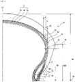
- FIG. 1 shows a sectional view in the width direction illustrating one example of a motorcycle tire of the present invention.
- FIG. 2 shows one side of the sectional view in the width direction of the motorcycle tire of FIG. 1 .
- a motorcycle tire 10 of the present invention has a tread portion 11 forming a ground contact area, and a pair of sidewall portions 12 and bead portions 13 extending from both ends thereof to the inside in the tire radial direction, respectively.
- the tire 10 of the present invention illustrated in the figure, includes a carcass 2 as a skeleton composed of at least one, two carcass plies 2a, 2b in the example shown, which extend toroidally between a pair of bead portions 13 and are folded and engaged around a pair of bead cores 1 respectively embedded in the pair of bead portions 13. Furthermore, a belt 3 composed of at least one, and in the example illustrated, three belt layers 3a-3c are arranged on the outer side of the carcass 2 in the tire radial direction.
- the present invention is characterized in that a flipper 4 is arranged between a carcass 2 and a bead core 1 to wrap the bead core 1 from the inner side in the tire radial direction, and an outer side end portion 4o of the flipper 4 in the tire width direction is rolled up to a tread portion 11 and extends to the inner side in the tire width direction from an end portion 3x of the belt 3 in the tire width direction.
- such a configuration can increase the rigidity of side portions to improve the handling stability of motorcycles and increase the durability of tires. Since side rigidity is increased by arrangement of the flipper 4, appropriate shock absorption can be maintained, and ride comfort is not compromised. This enables realization of a tire having increased longitudinal rigidity suitable also for large motorcycles, which are subject to much higher loads and torques than conventional tires.
- an outer side end portion 4o of the flipper 4 in the tire width direction is extended to the inner side of the tire width direction from the end portion 3x of the belt 3 in the tire width direction because the positions of the end portions of members are not coincident in the tire width direction to suppress stress concentration.
- a belt layer is made up of three pieces in the example illustrated, and can be made up of at least one piece, preferably two or more, and more preferably three or more, for example, one to five pieces, and particularly two to three pieces.
- the end portion 3x of the above-described belt 3 in the tire width direction means the end portion of the innermost belt 3a in the tire width direction that is the innermost in the tire radial direction and adjacent to a carcass 2 among belt layers 3a to 3c, as illustrated in the figure.
- the outer end portion 2o of the carcass 2 in the tire width direction preferably extends to the inner side of the tire width direction from the end portion 3x of the belt 3 in the tire width direction.
- Such a configuration allows end portions of each member to be positioned differently in the tire width direction, thereby suppressing stress concentration and preventing rigidity steps from occurring, thereby further improving durability.
- the outer end portion 2o of the carcass 2 in the tire width direction is positioned on the inner side of the belt 3 in the tire radial direction.
- the carcass ply is made up of two pieces in the example illustrated, but may be made up of at least one piece, preferably two or more pieces, and even three or more pieces.
- carcass plies are made up of two or more layers, as described above, usually, the outer end portion 2o in the tire width direction of the carcass ply 2b, which is one of the plurality of layers of carcass plies 2a and 2b and is folded around the bead core and rolled up to a higher position, should extend to the inner side of the tire width direction from the end portion 3x of the belt 3 in the tire width direction.
- a configuration in which one carcass ply 2b provided on the inner side of the tire radial direction extends to the inner side of the tire width direction from the end portion 3x of the above-described belt 3 in the tire width direction is suitable.
- the height of rolling up of the other carcass ply 2a is not limited, as illustrated in the figure, a height that does not reach the tread portion 11 is preferable from the viewpoint of preventing the side portions from becoming too rigid and maintaining the ride comfort.
- the ratio of the overlap width FL of the belt 3 and the flipper 4 to the overlap width CL of the belt 3 and the carcass 2, measured along the tire surface in the tire width direction is suitably in the range from 25% to 80%, and more suitably from 30% to 75%.
- the overlap width CL between the belt 3 and the carcass 2 is preferably from 3 to 25 mm, and more preferably from 5 to 20 mm.
- the overlap width FL between the belt 3 and the flipper 4 is preferably from 1 to 20 mm, and more preferably from 3 to 15 mm.
- the height FH of the inner end portion 4i of the flipper 4 in the tire width direction is preferably lower than the height SWH of the tire maximum width position, i.e., the tread end portion TE. This allows suppression of stress concentration while preventing rigidity steps from occurring, thereby further improving durability.
- the ratio of the height FH of the inner end portion 4i of the tire in the tire width direction of the flipper 4 to the height SWH of the tire maximum width position is preferably in the range of from 30% to less than 100%, and more preferably from 50% to 85%.
- the height FH of the inner end portion 4i of the flipper 4 in the tire width direction, the height SWH at the tire maximum width position, and the tire sectional height SH, which is described below, are defined with respect to a bead baseline BL.
- the bead baseline BL means a straight line parallel to the tire axis passing through the position of the rim diameter of a rim as specified in the above-described industrial standards in a tire width direction section.
- the only important point is the arrangement of the above-described flipper 4, which allows a desired effect of the present invention to be obtained.
- configurations such as materials and arrangement conditions of members other than the flipper 4 are not particularly restricted, and can be determined according to usual methods.
- a bead filler 5 can be arranged on the outer side of the bead core 1 in the tire radial direction, and a chaffer (reinforcement layer) 6 can be arranged on the inner side of the carcass 2 in the bead portion 13 in the tire radial direction.
- an inner liner not illustrated, can be arranged in the innermost layer of the tire.
- the cord angle of the ply cords in a carcass ply is suitably from 20° to 50° with respect to the tire equator CT at the tire crown.
- two or more carcass plies are provided, two or more carcass plies are arranged in such a manner that the direction of the cords of the two or more carcass plies intersect with each other.
- the end count of the ply cords in a carcass ply can suitably be from 3 to 10 cords/5 mm, which maintains sufficient rigidity in the side portions.
- the cord angle of the belt cords in a belt layer is suitably from 15° to 80°, and more suitably from 15° to 45° with respect to the tire equator CT.
- the belt layers are arranged in such a manner that the direction of the cords intersect each other.
- the end count of belt cords in a belt layer can suitably be from 2 to 10 cords/5 mm.
- the cord angle of a reinforcing cord at the flipper 4 is suitably from 20° to 60°, and more suitably from 30° to 55° with respect to the tire radial direction.
- the end count of reinforcing cords in a flipper can suitably be from 2 to 6 cords/5 mm, and more suitably from 3 to 4 cords/5 mm.
- the materials of organic fiber cords that can be suitably applied to a carcass ply, a belt layer, and a flipper in the tire of the present invention can be selected from polyamide (for example, nylon), polyethylene terephthalate (PET), polyethylene naphthalate (PEN), aramid (for example, Kevler (trade name)), and rayon, and the others having material properties comparable to those of these organic fiber materials, in a suitable combination, depending on the purpose and application.
- polyamide for example, nylon
- PET polyethylene terephthalate
- PEN polyethylene naphthalate
- aramid for example, Kevler (trade name)
- rayon rayon
- the ratio of the height SWH at the tire maximum width position to the tire sectional height SH is preferably in the range of from 40% to 75%.
- the ratio SWH/SH between the tire sectional height SH and the height SWH at the tire maximum width position expressed as a percentage, in the range of from 40% to 75%, a tire having an adequate ground contact surface and more excellent handling stability can be obtained.
- handling stability can be improved in a banked state.
- the tire sectional height SH refers to 1/2 of the difference between the outer diameter of a tire, and the rim diameter of a rim that is specified in the above-described industrial standards.
- the negative ratio is preferably in the range of from 5% to 30%.
- the negative ratio is the ratio of the area of grooves to the area of the tread surface assuming no grooves, meaning the ratio of the groove area, excluding sipes, to the area of the tread portion.
- the tire of the present invention is particularly suitable as a rear tire for motorcycles.
- the tire of the invention can be applied to both radial and bias structures, and is useful as a bias tire.
- a motorcycle pneumatic bias tire of the tire size 180/65B16 having the structure illustrated in FIGS. 1 and 2 was prepared. As illustrated in the figure, this tire was a rear tire including a carcass as a skeleton composed of two carcass plies and a belt composed of three belt layers located on the outer side in the tire radial direction, and a flipper that wraps a bead core from the inner side in the tire radial direction was arranged between the carcass and the bead core.
- the two carcass plies were reinforced by ply cords (material: polyamide) with an end count of 4.6 per 5 mm and were arranged to intersect each other at a cord angle of ⁇ 35° with respect to the tire equator CT.
- the three belt layers were reinforced by belt cords (materials: aramid, aramid, and polyamide from the inner layer) with an end count of 4.4 per 5 mm, arranged to intersect each other at a cord angle of ⁇ 20° with respect to the tire equator CT.
- the flippers were reinforced by reinforcing cords (material: aramid) with an end count of 3.6 per 5 mm and a cord angle of 45° with respect to the tire radial direction.
- the height of the inner end portion of the flipper in the tire width direction was lower than the height of the tire maximum width position.
- the ratio of the height SWH of the tire maximum width position to the tire sectional height SH was 59.5%, with a negative ratio of 12.6%.
- a test tire of Comparative Example 1 was prepared in the same manner as in Example 1, except that the flipper was not placed, in accordance with the conditions shown in Table 1 below.
- a test tire of Comparative Example 2 was prepared in the same manner as in Example 1, except that the position of the outer end portion of the flipper in the tire width direction was changed to a position where the flipper does not overlap with the end portion of the belt in the tire width direction, in accordance with the conditions shown in Table 1 below.
- Example 1 and Comparative Examples 1 and 2 were mounted on a 1,800 cc class, high-load, high-torque, large motorcycle, and the following evaluations were conducted. A commercially available front tire was used. The results are shown together in Table 1 below.
- ⁇ 2 The value of the overlap width CL between the belt and the carcass, measured along the tire surface in the tire width direction.
- ⁇ 3) The ratio of the overlap width FL between the belt and the flipper to the overlap width CL between the belt and the carcass, measured along the tire surface in the tire width direction, expressed as a percentage.
- ⁇ 4) The ratio of the height FH of the inner end portion of the tire width direction of the flipper to the height SWH of the tire maximum width position, expressed as a percentage.
Landscapes
- Engineering & Computer Science (AREA)
- Mechanical Engineering (AREA)
- Tires In General (AREA)
Abstract
Description
- This invention relates to a motorcycle tire (hereinafter also referred to simply as "tire"), and more specifically, to a pneumatic tire for motorcycles in which a side portion is improved.
- Typically, the basic structure of a motorcycle tire includes at least one carcass ply extending toroidally between a pair of bead portions as a skeleton and at least one belt layer arranged outside the tire radial direction of the carcass ply as a reinforcing member of a tread portion.
- As a prior art relating to motorcycle tires, for example, Patent Document 1 discloses, for the purpose of solving lack of lateral force and lack of durability caused by lack of rigidity of a side portion, a motorcycle pneumatic radial tire in which a flipper layer is arranged on the outside of a carcass ply, folded around a bead core from the inside to the outside of the tire, the folded end of which terminates between the carcass ply and the belt layer.
-
Patent Document 2 discloses a motorcycle pneumatic bias tire, wherein for a carcass layer formed by at least two carcass plies, cords of carcass plies have a predetermined difference in initial tensile resistance, end count, and constant load intermediate elongation and are inclined in opposite directions to the tire equator at a predetermined angle with respect to each other, for the purpose of enabling both tire case rigidity and tire case flexibility to improve ground contact and handling stability. -
- [Patent Document 1]
JP 2013-166526A - [Patent Document2]
JP H11-222007A - In recent years, as motorcycles have become larger, the weight of vehicles has increased, and motorcycle tires that support such vehicles are also required to cope with this. In particular, motorcycle tires mounted on large motorcycles, which are subject to high loads and torques, are required to have sufficient longitudinal rigidity, excellent handling stability, and excellent durability.
- It is therefore an object of the present invention to provide a motorcycle tire having excellent handling stability and durability.
- As a result of intensive study, the present inventor found that the above-described problem can be solved by arranging a flipper between a carcass and a bead core, and by rolling up an outer side end portion of the flipper in the tire width direction to the inner side in the tire width direction from an end portion of a belt layer in the tire width direction, thereby completing the present invention.
- In other words, the present invention is a motorcycle tire including a carcass as a skeleton composed of at least one carcass ply extending toroidally between a pair of bead portions and folded and engaged around a pair of bead cores embedded in each of the pair of bead portions and a belt composed of at least one belt layer arranged on the outer side of the carcass in the tire radial direction, wherein
a flipper is arranged between the carcass and the bead core to wrap the bead core from the inside in the tire radial direction, and an outer side end portion of the flipper in the tire width direction extends to the inside in the tire width direction from an end portion of the belt in the tire width direction. - In the tire of the present invention, it is preferable that an outer end portion of the carcass in the tire width direction extends to the inner side in the tire width direction from the end portion of the belt in the tire width direction. In the tire of the present invention, it is preferable that a height FH of an inner end portion of the flipper in the tire width direction is lower than a height SWH of the tire maximum width position, and it is more preferable that the ratio of the height FH of the inner end portion of the flipper in the tire width direction to the height SWH of the tire maximum width position is from 30% to less than 100%.
- Furthermore, in the tire of the present invention, it is preferable that the ratio of an overlap width FL between the belt and the flipper to an overlap width CL between the belt and the carcass, measured along the tire surface in the tire width direction, is in the range of from 25% to 80%. The tire of the present invention is particularly suitable as a bias tire.
- In the present invention, unless otherwise specified, the dimensions of a tire are those measured under no load, with the tire mounted on rims specified in the industrial standards in effect in a region where the tire is produced and used, and filled with an internal pressure specified in such industrial standards. The above-described industry standards are, for example, JATMA (Japan Automobile Tyre Manufacturers Association) YEAR BOOK in Japan, ETRTO (European Tyre and Rim Technical Organisation) STANDARD MANUAL in Europe, and TRA (THE TIRE and RIM ASSOCIATION INC.) YEAR BOOK in the United States.
- According to the present invention, the above-described configuration enables realization of a motorcycle tire having excellent handling stability and durability.
-
-
FIG. 1 is a sectional view in the width direction illustrating one example of a motorcycle tire of the present invention. -
FIG. 2 is one side of the sectional view in the width direction of the motorcycle tire ofFIG. 1 . - In the following, embodiments of the present invention will be described in detail with reference to the drawings.
-
FIG. 1 shows a sectional view in the width direction illustrating one example of a motorcycle tire of the present invention.FIG. 2 shows one side of the sectional view in the width direction of the motorcycle tire ofFIG. 1 . As illustrated, amotorcycle tire 10 of the present invention has a tread portion 11 forming a ground contact area, and a pair ofsidewall portions 12 and beadportions 13 extending from both ends thereof to the inside in the tire radial direction, respectively. - The
tire 10 of the present invention, illustrated in the figure, includes acarcass 2 as a skeleton composed of at least one, twocarcass plies bead portions 13 and are folded and engaged around a pair of bead cores 1 respectively embedded in the pair ofbead portions 13. Furthermore, abelt 3 composed of at least one, and in the example illustrated, threebelt layers 3a-3c are arranged on the outer side of thecarcass 2 in the tire radial direction. - The present invention is characterized in that a
flipper 4 is arranged between acarcass 2 and a bead core 1 to wrap the bead core 1 from the inner side in the tire radial direction, and an outer side end portion 4o of theflipper 4 in the tire width direction is rolled up to a tread portion 11 and extends to the inner side in the tire width direction from anend portion 3x of thebelt 3 in the tire width direction. - According to the present invention, such a configuration can increase the rigidity of side portions to improve the handling stability of motorcycles and increase the durability of tires. Since side rigidity is increased by arrangement of the
flipper 4, appropriate shock absorption can be maintained, and ride comfort is not compromised. This enables realization of a tire having increased longitudinal rigidity suitable also for large motorcycles, which are subject to much higher loads and torques than conventional tires. - In the present invention, an outer side end portion 4o of the
flipper 4 in the tire width direction is extended to the inner side of the tire width direction from theend portion 3x of thebelt 3 in the tire width direction because the positions of the end portions of members are not coincident in the tire width direction to suppress stress concentration. - Here, in the tire of the present invention, a belt layer is made up of three pieces in the example illustrated, and can be made up of at least one piece, preferably two or more, and more preferably three or more, for example, one to five pieces, and particularly two to three pieces. When a belt layer is made up of two or more layers, the
end portion 3x of the above-describedbelt 3 in the tire width direction means the end portion of theinnermost belt 3a in the tire width direction that is the innermost in the tire radial direction and adjacent to acarcass 2 amongbelt layers 3a to 3c, as illustrated in the figure. - As illustrated in the figure, in the present invention, the outer end portion 2o of the
carcass 2 in the tire width direction preferably extends to the inner side of the tire width direction from theend portion 3x of thebelt 3 in the tire width direction. Such a configuration allows end portions of each member to be positioned differently in the tire width direction, thereby suppressing stress concentration and preventing rigidity steps from occurring, thereby further improving durability. In this case, the outer end portion 2o of thecarcass 2 in the tire width direction is positioned on the inner side of thebelt 3 in the tire radial direction. - Here, in the tire of the present invention, the carcass ply is made up of two pieces in the example illustrated, but may be made up of at least one piece, preferably two or more pieces, and even three or more pieces. When carcass plies are made up of two or more layers, as described above, usually, the outer end portion 2o in the tire width direction of the
carcass ply 2b, which is one of the plurality of layers ofcarcass plies end portion 3x of thebelt 3 in the tire width direction. In particular, from the viewpoint of durability and ride comfort, a configuration in which onecarcass ply 2b provided on the inner side of the tire radial direction extends to the inner side of the tire width direction from theend portion 3x of the above-describedbelt 3 in the tire width direction is suitable. Although the height of rolling up of theother carcass ply 2a is not limited, as illustrated in the figure, a height that does not reach the tread portion 11 is preferable from the viewpoint of preventing the side portions from becoming too rigid and maintaining the ride comfort. - In the present invention, the ratio of the overlap width FL of the
belt 3 and theflipper 4 to the overlap width CL of thebelt 3 and thecarcass 2, measured along the tire surface in the tire width direction, is suitably in the range from 25% to 80%, and more suitably from 30% to 75%. By setting the ratio FL/CL of the overlap width CL between thebelt 3 and thecarcass 2 to the overlap width FL between thebelt 3 and theflipper 4 in the range of from 25% to 80%, expressed as a percentage, when compared at the so-called peripheral length, stress concentration can be suppressed and rigidity steps can be avoided, thereby further improving durability. - Specifically, the overlap width CL between the
belt 3 and thecarcass 2 is preferably from 3 to 25 mm, and more preferably from 5 to 20 mm. Specifically, the overlap width FL between thebelt 3 and theflipper 4 is preferably from 1 to 20 mm, and more preferably from 3 to 15 mm. - In the present invention, the height FH of the
inner end portion 4i of theflipper 4 in the tire width direction is preferably lower than the height SWH of the tire maximum width position, i.e., the tread end portion TE. This allows suppression of stress concentration while preventing rigidity steps from occurring, thereby further improving durability. - Specifically, the ratio of the height FH of the
inner end portion 4i of the tire in the tire width direction of theflipper 4 to the height SWH of the tire maximum width position is preferably in the range of from 30% to less than 100%, and more preferably from 50% to 85%. By setting the ratio FH/SWH between the height SWH of the tire maximum width position and the height FH of theinner end portion 4i of theflipper 4 in the tire width direction, expressed as a percentage, to the range of from 30% to less than 100%, stress concentration can be more effectively suppressed and no rigidity steps can be generated, thereby further improving durability. - In the present invention, the height FH of the
inner end portion 4i of theflipper 4 in the tire width direction, the height SWH at the tire maximum width position, and the tire sectional height SH, which is described below, are defined with respect to a bead baseline BL. The bead baseline BL means a straight line parallel to the tire axis passing through the position of the rim diameter of a rim as specified in the above-described industrial standards in a tire width direction section. - In the present invention, the only important point is the arrangement of the above-described
flipper 4, which allows a desired effect of the present invention to be obtained. In the present invention, configurations such as materials and arrangement conditions of members other than theflipper 4 are not particularly restricted, and can be determined according to usual methods. For example, in the tire of the present invention, a bead filler 5 can be arranged on the outer side of the bead core 1 in the tire radial direction, and a chaffer (reinforcement layer) 6 can be arranged on the inner side of thecarcass 2 in thebead portion 13 in the tire radial direction. Furthermore, an inner liner, not illustrated, can be arranged in the innermost layer of the tire. - In the tire of the present invention, the cord angle of the ply cords in a carcass ply is suitably from 20° to 50° with respect to the tire equator CT at the tire crown. When two or more carcass plies are provided, two or more carcass plies are arranged in such a manner that the direction of the cords of the two or more carcass plies intersect with each other. The end count of the ply cords in a carcass ply can suitably be from 3 to 10 cords/5 mm, which maintains sufficient rigidity in the side portions.
- In the tire of the present invention, the cord angle of the belt cords in a belt layer is suitably from 15° to 80°, and more suitably from 15° to 45° with respect to the tire equator CT. When two or more belt layers are provided, at least some of the belt layers are arranged in such a manner that the direction of the cords intersect each other. The end count of belt cords in a belt layer can suitably be from 2 to 10 cords/5 mm.
- Furthermore, in the tire of the present invention, the cord angle of a reinforcing cord at the
flipper 4 is suitably from 20° to 60°, and more suitably from 30° to 55° with respect to the tire radial direction. The end count of reinforcing cords in a flipper can suitably be from 2 to 6 cords/5 mm, and more suitably from 3 to 4 cords/5 mm. - Furthermore, the materials of organic fiber cords that can be suitably applied to a carcass ply, a belt layer, and a flipper in the tire of the present invention can be selected from polyamide (for example, nylon), polyethylene terephthalate (PET), polyethylene naphthalate (PEN), aramid (for example, Kevler (trade name)), and rayon, and the others having material properties comparable to those of these organic fiber materials, in a suitable combination, depending on the purpose and application.
- Furthermore, in the tire of the present invention, the ratio of the height SWH at the tire maximum width position to the tire sectional height SH is preferably in the range of from 40% to 75%. By setting the ratio SWH/SH between the tire sectional height SH and the height SWH at the tire maximum width position, expressed as a percentage, in the range of from 40% to 75%, a tire having an adequate ground contact surface and more excellent handling stability can be obtained. In particular, during cornering traveling of motorcycles, handling stability can be improved in a banked state. Here, the tire sectional height SH refers to 1/2 of the difference between the outer diameter of a tire, and the rim diameter of a rim that is specified in the above-described industrial standards.
- Furthermore, in the tire of the present invention, the negative ratio is preferably in the range of from 5% to 30%. By setting the negative ratio in the above-described range, handling stability and ride comfort can be favorably maintained while ensuring drainage. Here, the negative ratio is the ratio of the area of grooves to the area of the tread surface assuming no grooves, meaning the ratio of the groove area, excluding sipes, to the area of the tread portion.
- The tire of the present invention is particularly suitable as a rear tire for motorcycles. The tire of the invention can be applied to both radial and bias structures, and is useful as a bias tire.
- Hereinafter, the present invention will be described in more detail by way of Examples.
- A motorcycle pneumatic bias tire of the tire size 180/65B16 having the structure illustrated in
FIGS. 1 and2 was prepared. As illustrated in the figure, this tire was a rear tire including a carcass as a skeleton composed of two carcass plies and a belt composed of three belt layers located on the outer side in the tire radial direction, and a flipper that wraps a bead core from the inner side in the tire radial direction was arranged between the carcass and the bead core. - The two carcass plies were reinforced by ply cords (material: polyamide) with an end count of 4.6 per 5 mm and were arranged to intersect each other at a cord angle of ±35° with respect to the tire equator CT. The three belt layers were reinforced by belt cords (materials: aramid, aramid, and polyamide from the inner layer) with an end count of 4.4 per 5 mm, arranged to intersect each other at a cord angle of ±20° with respect to the tire equator CT. Furthermore, the flippers were reinforced by reinforcing cords (material: aramid) with an end count of 3.6 per 5 mm and a cord angle of 45° with respect to the tire radial direction.
- In the tire of Example 1, the outer end portion of the flipper in the tire width direction and the outer end portion of the carcass ply in the tire width direction, which is located on the inner side in the tire radial direction, extended to the inner side of the tire width direction from the end portion of the belt in the tire width direction. The height of the inner end portion of the flipper in the tire width direction was lower than the height of the tire maximum width position. The ratio of the height SWH of the tire maximum width position to the tire sectional height SH was 59.5%, with a negative ratio of 12.6%.
- A test tire of Comparative Example 1 was prepared in the same manner as in Example 1, except that the flipper was not placed, in accordance with the conditions shown in Table 1 below.
- A test tire of Comparative Example 2 was prepared in the same manner as in Example 1, except that the position of the outer end portion of the flipper in the tire width direction was changed to a position where the flipper does not overlap with the end portion of the belt in the tire width direction, in accordance with the conditions shown in Table 1 below.
- These rear tires of Example 1 and Comparative Examples 1 and 2 were mounted on a 1,800 cc class, high-load, high-torque, large motorcycle, and the following evaluations were conducted. A commercially available front tire was used. The results are shown together in Table 1 below.
- Driving tests were conducted on each vehicle to evaluate the handling stability in cornering traveling at high speeds by sensory evaluation by a test driver. The results are shown with the test tire in Comparative Example 2 as the standard.
- The value of the load at which a tire was damaged when each vehicle was run with load applied in a stepwise manner was evaluated by converting the value of the load at which the tire was damaged into an index value with Example 1 as 100. Higher values indicate more excellent durability.
[Table 1] Example 1 Comparative Example 1 Comparative Example 2 FL (mm) ∗1 5 - -1 CL (mm) ∗2 10 10 10 FL/CL (%) ∗3 50 - -10 FH/SWH (%) ∗4 78 - 97 Carcass ply (pieces) 2 2 2 Handling stability Favorable Poor Standard Durability (index) 100 88 88 ∗1) The value of the overlap width FL between the belt and the flipper, measured along the tire surface in the tire width direction.
∗2) The value of the overlap width CL between the belt and the carcass, measured along the tire surface in the tire width direction.
∗3) The ratio of the overlap width FL between the belt and the flipper to the overlap width CL between the belt and the carcass, measured along the tire surface in the tire width direction, expressed as a percentage.
∗4) The ratio of the height FH of the inner end portion of the tire width direction of the flipper to the height SWH of the tire maximum width position, expressed as a percentage. - As shown in the above-described table, it is clear that both handling stability and durability are improved in the tire of Example 1 in which the flipper is arranged between the carcass and the bead core in such a manner that the outer end portion in the tire width direction extends to the inner side of the tire width direction from the end portion of the belt in the tire width direction compared to the tires of Comparative Examples 1 and 2, which do not satisfy these conditions.
-
- 1
- Bead core
- 2
- Carcass
- 2a, 2b
- Carcass ply
- 2o
- Outer end portion of carcass in tire width direction
- 3
- Belt
- 3a to 3c
- Belt layer
- 3x
- End portion of belt in in tire width direction
- 4
- Flipper
- 4i
- Inner side end portion of flipper in tire width direction
- 4o
- Outer side end portion of flipper in tire width direction
- 5
- Bead filler
- 6
- Chafer (reinforcing layer)
- 10
- Motorcycle tire
- 11
- Tread portion
- 12
- Sidewall portion
- 13
- Bead portion
Claims (6)
- A motorcycle tire comprising a carcass as a skeleton composed of at least one carcass ply extending toroidally between a pair of bead portions and folded and engaged around a pair of bead cores embedded in each of the pair of bead portions and a belt composed of at least one belt layer arranged on the outer side of the carcass in the tire radial direction, whereina flipper is arranged between the carcass and the bead core to wrap the bead core from the inside in the tire radial direction, andan outer side end portion of the flipper in the tire width direction extends to the inside in the tire width direction from an end portion of the belt in the tire width direction.
- The motorcycle tire according to claim 1, wherein an outer end portion of the carcass in the tire width direction extends to the inner side in the tire width direction from the end portion of the belt in the tire width direction.
- The motorcycle tire according to claim 1 or 2, wherein a height FH of an inner end portion of the flipper in the tire width direction is lower than a height SWH of a tire maximum width position.
- The motorcycle tire according to claim 3, wherein the ratio of the height FH of the inner end portion of the flipper in the tire width direction to the height SWH of the tire maximum width position is from 30% to less than 100%.
- The motorcycle tire according to any one of claims 2 to 4, wherein the ratio of an overlap width FL between the belt and the flipper to an overlap width CL between the belt and the carcass, measured along the tire surface in the tire width direction, is in the range of from 25% to 80%.
- The motorcycle tire according to any one of claims 1 to 5, wherein the motorcycle tire is a bias tire.
Applications Claiming Priority (2)
| Application Number | Priority Date | Filing Date | Title |
|---|---|---|---|
| JP2020026557A JP7461157B2 (en) | 2020-02-19 | 2020-02-19 | Motorcycle Tires |
| PCT/JP2021/000666 WO2021166489A1 (en) | 2020-02-19 | 2021-01-12 | Motorcycle tire |
Publications (2)
| Publication Number | Publication Date |
|---|---|
| EP4108473A1 true EP4108473A1 (en) | 2022-12-28 |
| EP4108473A4 EP4108473A4 (en) | 2023-07-19 |
Family
ID=77392095
Family Applications (1)
| Application Number | Title | Priority Date | Filing Date |
|---|---|---|---|
| EP21756925.0A Pending EP4108473A4 (en) | 2020-02-19 | 2021-01-12 | MOTORCYCLE TIRES |
Country Status (4)
| Country | Link |
|---|---|
| US (1) | US12151524B2 (en) |
| EP (1) | EP4108473A4 (en) |
| JP (1) | JP7461157B2 (en) |
| WO (1) | WO2021166489A1 (en) |
Cited By (1)
| Publication number | Priority date | Publication date | Assignee | Title |
|---|---|---|---|---|
| EP4596261A1 (en) * | 2024-01-30 | 2025-08-06 | Sumitomo Rubber Industries, Ltd. | Motorcycle tire |
Family Cites Families (13)
| Publication number | Priority date | Publication date | Assignee | Title |
|---|---|---|---|---|
| DE2905244A1 (en) * | 1979-02-12 | 1980-08-14 | Continental Gummi Werke Ag | VEHICLE TIRES |
| JPS5822704A (en) * | 1981-08-04 | 1983-02-10 | Bridgestone Corp | Pneumatic semiradial tire for motorcycle |
| JPS59179410A (en) * | 1983-03-30 | 1984-10-12 | Yokohama Rubber Co Ltd:The | Pneumatic radial tire for motorcycle |
| US4854362A (en) * | 1988-05-23 | 1989-08-08 | The Goodyear Tire & Rubber Company | Pneumatic tire |
| IT1243872B (en) | 1990-10-29 | 1994-06-28 | Pirelli Transmissioni Ind Spa | RADIAL TIRE WITH SIDE REINFORCEMENT ELEMENT. |
| JP3702911B2 (en) * | 1996-02-02 | 2005-10-05 | 横浜ゴム株式会社 | Pneumatic radial tire |
| JPH11222007A (en) | 1998-02-10 | 1999-08-17 | Bridgestone Corp | Pneumatic bias tire for motorcycle |
| JP4299616B2 (en) * | 2003-09-04 | 2009-07-22 | 住友ゴム工業株式会社 | Pneumatic radial tire |
| WO2006098112A1 (en) * | 2005-03-16 | 2006-09-21 | Bridgestone Corporation | Pneumatic radial tire for motorcycle |
| DE102011054636A1 (en) * | 2011-10-20 | 2013-04-25 | Continental Reifen Deutschland Gmbh | Pneumatic tires for a motorcycle, in particular for a youngtimer motorcycle |
| JP5865109B2 (en) | 2012-02-17 | 2016-02-17 | 株式会社ブリヂストン | Pneumatic radial tire for motorcycles |
| JP6129477B2 (en) * | 2012-03-15 | 2017-05-17 | 東洋ゴム工業株式会社 | Pneumatic tire |
| FR3006628B1 (en) * | 2013-06-10 | 2015-05-29 | Michelin & Cie | CARCASS AND PNEUMATIC TOP FOR MOTORCYCLE FRAME |
-
2020
- 2020-02-19 JP JP2020026557A patent/JP7461157B2/en active Active
-
2021
- 2021-01-12 US US17/797,046 patent/US12151524B2/en active Active
- 2021-01-12 EP EP21756925.0A patent/EP4108473A4/en active Pending
- 2021-01-12 WO PCT/JP2021/000666 patent/WO2021166489A1/en not_active Ceased
Cited By (1)
| Publication number | Priority date | Publication date | Assignee | Title |
|---|---|---|---|---|
| EP4596261A1 (en) * | 2024-01-30 | 2025-08-06 | Sumitomo Rubber Industries, Ltd. | Motorcycle tire |
Also Published As
| Publication number | Publication date |
|---|---|
| US12151524B2 (en) | 2024-11-26 |
| JP2021130387A (en) | 2021-09-09 |
| JP7461157B2 (en) | 2024-04-03 |
| EP4108473A4 (en) | 2023-07-19 |
| US20230107811A1 (en) | 2023-04-06 |
| WO2021166489A1 (en) | 2021-08-26 |
Similar Documents
| Publication | Publication Date | Title |
|---|---|---|
| EP3967517B1 (en) | Heavy duty pneumatic tire | |
| EP2085251B1 (en) | Pneumatic radial tire | |
| EP0844110B1 (en) | Pneumatic tyre | |
| EP1849626B1 (en) | Pneumatic tire for racing | |
| EP2332744A2 (en) | Pneumatic tire | |
| EP2186656B9 (en) | Pneumatic tire | |
| EP1683654B1 (en) | Runflat tire | |
| CN111703259A (en) | Heavy load pneumatic tire | |
| EP1859961B1 (en) | Pneumatic tire for motorcycle | |
| EP2196328A1 (en) | Tire pair for two-wheeled motor vehicle | |
| EP2543522A1 (en) | Two-wheeled automotive vehicle tire | |
| EP3059100B1 (en) | Pneumatic tire | |
| EP3153331A1 (en) | Pneumatic tire | |
| JP6274547B2 (en) | Pneumatic tire | |
| EP3470241A1 (en) | Three-wheeled vehicle tire | |
| US12151524B2 (en) | Motorcycle tire | |
| JP6982523B2 (en) | Tricycle tires | |
| US20230241922A1 (en) | Pneumatic tire | |
| EP1785286A1 (en) | Pneumatic tire for motorcycle | |
| EP1642752B1 (en) | Radial tyre for motorcycle | |
| JP5680881B2 (en) | Pneumatic tire | |
| JP2006290164A (en) | Pneumatic tire for motorcycle | |
| EP4360907A1 (en) | Pneumatic radial tire for passenger vehicle | |
| JP5040232B2 (en) | Pneumatic tire | |
| WO2022255126A1 (en) | Motorcycle tire |
Legal Events
| Date | Code | Title | Description |
|---|---|---|---|
| STAA | Information on the status of an ep patent application or granted ep patent |
Free format text: STATUS: THE INTERNATIONAL PUBLICATION HAS BEEN MADE |
|
| PUAI | Public reference made under article 153(3) epc to a published international application that has entered the european phase |
Free format text: ORIGINAL CODE: 0009012 |
|
| STAA | Information on the status of an ep patent application or granted ep patent |
Free format text: STATUS: REQUEST FOR EXAMINATION WAS MADE |
|
| 17P | Request for examination filed |
Effective date: 20220916 |
|
| AK | Designated contracting states |
Kind code of ref document: A1 Designated state(s): AL AT BE BG CH CY CZ DE DK EE ES FI FR GB GR HR HU IE IS IT LI LT LU LV MC MK MT NL NO PL PT RO RS SE SI SK SM TR |
|
| DAV | Request for validation of the european patent (deleted) | ||
| DAX | Request for extension of the european patent (deleted) | ||
| A4 | Supplementary search report drawn up and despatched |
Effective date: 20230620 |
|
| RIC1 | Information provided on ipc code assigned before grant |
Ipc: B60C 15/00 20060101ALI20230614BHEP Ipc: B60C 3/04 20060101ALI20230614BHEP Ipc: B60C 9/08 20060101ALI20230614BHEP Ipc: B60C 15/04 20060101ALI20230614BHEP Ipc: B60C 15/06 20060101ALI20230614BHEP Ipc: B60C 9/06 20060101AFI20230614BHEP |
|
| STAA | Information on the status of an ep patent application or granted ep patent |
Free format text: STATUS: EXAMINATION IS IN PROGRESS |
|
| 17Q | First examination report despatched |
Effective date: 20250220 |