EP4108276A1 - Accessory devices, systems, and methods for medicine administration and tracking - Google Patents
Accessory devices, systems, and methods for medicine administration and tracking Download PDFInfo
- Publication number
- EP4108276A1 EP4108276A1 EP22178950.6A EP22178950A EP4108276A1 EP 4108276 A1 EP4108276 A1 EP 4108276A1 EP 22178950 A EP22178950 A EP 22178950A EP 4108276 A1 EP4108276 A1 EP 4108276A1
- Authority
- EP
- European Patent Office
- Prior art keywords
- light
- delivery device
- medicine delivery
- dose
- cap
- Prior art date
- Legal status (The legal status is an assumption and is not a legal conclusion. Google has not performed a legal analysis and makes no representation as to the accuracy of the status listed.)
- Pending
Links
Images


Classifications
-
- A—HUMAN NECESSITIES
- A61—MEDICAL OR VETERINARY SCIENCE; HYGIENE
- A61M—DEVICES FOR INTRODUCING MEDIA INTO, OR ONTO, THE BODY; DEVICES FOR TRANSDUCING BODY MEDIA OR FOR TAKING MEDIA FROM THE BODY; DEVICES FOR PRODUCING OR ENDING SLEEP OR STUPOR
- A61M5/00—Devices for bringing media into the body in a subcutaneous, intra-vascular or intramuscular way; Accessories therefor, e.g. filling or cleaning devices, arm-rests
- A61M5/178—Syringes
- A61M5/31—Details
- A61M5/315—Pistons; Piston-rods; Guiding, blocking or restricting the movement of the rod or piston; Appliances on the rod for facilitating dosing ; Dosing mechanisms
- A61M5/31565—Administration mechanisms, i.e. constructional features, modes of administering a dose
- A61M5/31566—Means improving security or handling thereof
- A61M5/31568—Means keeping track of the total dose administered, e.g. since the cartridge was inserted
-
- G—PHYSICS
- G16—INFORMATION AND COMMUNICATION TECHNOLOGY [ICT] SPECIALLY ADAPTED FOR SPECIFIC APPLICATION FIELDS
- G16H—HEALTHCARE INFORMATICS, i.e. INFORMATION AND COMMUNICATION TECHNOLOGY [ICT] SPECIALLY ADAPTED FOR THE HANDLING OR PROCESSING OF MEDICAL OR HEALTHCARE DATA
- G16H20/00—ICT specially adapted for therapies or health-improving plans, e.g. for handling prescriptions, for steering therapy or for monitoring patient compliance
- G16H20/10—ICT specially adapted for therapies or health-improving plans, e.g. for handling prescriptions, for steering therapy or for monitoring patient compliance relating to drugs or medications, e.g. for ensuring correct administration to patients
- G16H20/17—ICT specially adapted for therapies or health-improving plans, e.g. for handling prescriptions, for steering therapy or for monitoring patient compliance relating to drugs or medications, e.g. for ensuring correct administration to patients delivered via infusion or injection
-
- A—HUMAN NECESSITIES
- A61—MEDICAL OR VETERINARY SCIENCE; HYGIENE
- A61M—DEVICES FOR INTRODUCING MEDIA INTO, OR ONTO, THE BODY; DEVICES FOR TRANSDUCING BODY MEDIA OR FOR TAKING MEDIA FROM THE BODY; DEVICES FOR PRODUCING OR ENDING SLEEP OR STUPOR
- A61M5/00—Devices for bringing media into the body in a subcutaneous, intra-vascular or intramuscular way; Accessories therefor, e.g. filling or cleaning devices, arm-rests
- A61M5/178—Syringes
- A61M5/24—Ampoule syringes, i.e. syringes with needle for use in combination with replaceable ampoules or carpules, e.g. automatic
- A61M5/2422—Ampoule syringes, i.e. syringes with needle for use in combination with replaceable ampoules or carpules, e.g. automatic using emptying means to expel or eject media, e.g. pistons, deformation of the ampoule, or telescoping of the ampoule
-
- A—HUMAN NECESSITIES
- A61—MEDICAL OR VETERINARY SCIENCE; HYGIENE
- A61M—DEVICES FOR INTRODUCING MEDIA INTO, OR ONTO, THE BODY; DEVICES FOR TRANSDUCING BODY MEDIA OR FOR TAKING MEDIA FROM THE BODY; DEVICES FOR PRODUCING OR ENDING SLEEP OR STUPOR
- A61M5/00—Devices for bringing media into the body in a subcutaneous, intra-vascular or intramuscular way; Accessories therefor, e.g. filling or cleaning devices, arm-rests
- A61M5/178—Syringes
- A61M5/31—Details
- A61M5/315—Pistons; Piston-rods; Guiding, blocking or restricting the movement of the rod or piston; Appliances on the rod for facilitating dosing ; Dosing mechanisms
- A61M5/31525—Dosing
-
- A—HUMAN NECESSITIES
- A61—MEDICAL OR VETERINARY SCIENCE; HYGIENE
- A61M—DEVICES FOR INTRODUCING MEDIA INTO, OR ONTO, THE BODY; DEVICES FOR TRANSDUCING BODY MEDIA OR FOR TAKING MEDIA FROM THE BODY; DEVICES FOR PRODUCING OR ENDING SLEEP OR STUPOR
- A61M5/00—Devices for bringing media into the body in a subcutaneous, intra-vascular or intramuscular way; Accessories therefor, e.g. filling or cleaning devices, arm-rests
- A61M5/178—Syringes
- A61M5/31—Details
- A61M5/315—Pistons; Piston-rods; Guiding, blocking or restricting the movement of the rod or piston; Appliances on the rod for facilitating dosing ; Dosing mechanisms
- A61M5/31533—Dosing mechanisms, i.e. setting a dose
- A61M5/31545—Setting modes for dosing
-
- A—HUMAN NECESSITIES
- A61—MEDICAL OR VETERINARY SCIENCE; HYGIENE
- A61M—DEVICES FOR INTRODUCING MEDIA INTO, OR ONTO, THE BODY; DEVICES FOR TRANSDUCING BODY MEDIA OR FOR TAKING MEDIA FROM THE BODY; DEVICES FOR PRODUCING OR ENDING SLEEP OR STUPOR
- A61M5/00—Devices for bringing media into the body in a subcutaneous, intra-vascular or intramuscular way; Accessories therefor, e.g. filling or cleaning devices, arm-rests
- A61M5/178—Syringes
- A61M5/31—Details
- A61M5/32—Needles; Details of needles pertaining to their connection with syringe or hub; Accessories for bringing the needle into, or holding the needle on, the body; Devices for protection of needles
- A61M5/3202—Devices for protection of the needle before use, e.g. caps
-
- G—PHYSICS
- G16—INFORMATION AND COMMUNICATION TECHNOLOGY [ICT] SPECIALLY ADAPTED FOR SPECIFIC APPLICATION FIELDS
- G16H—HEALTHCARE INFORMATICS, i.e. INFORMATION AND COMMUNICATION TECHNOLOGY [ICT] SPECIALLY ADAPTED FOR THE HANDLING OR PROCESSING OF MEDICAL OR HEALTHCARE DATA
- G16H40/00—ICT specially adapted for the management or administration of healthcare resources or facilities; ICT specially adapted for the management or operation of medical equipment or devices
- G16H40/60—ICT specially adapted for the management or administration of healthcare resources or facilities; ICT specially adapted for the management or operation of medical equipment or devices for the operation of medical equipment or devices
-
- A—HUMAN NECESSITIES
- A61—MEDICAL OR VETERINARY SCIENCE; HYGIENE
- A61M—DEVICES FOR INTRODUCING MEDIA INTO, OR ONTO, THE BODY; DEVICES FOR TRANSDUCING BODY MEDIA OR FOR TAKING MEDIA FROM THE BODY; DEVICES FOR PRODUCING OR ENDING SLEEP OR STUPOR
- A61M5/00—Devices for bringing media into the body in a subcutaneous, intra-vascular or intramuscular way; Accessories therefor, e.g. filling or cleaning devices, arm-rests
- A61M5/178—Syringes
- A61M5/31—Details
- A61M2005/3125—Details specific display means, e.g. to indicate dose setting
-
- A—HUMAN NECESSITIES
- A61—MEDICAL OR VETERINARY SCIENCE; HYGIENE
- A61M—DEVICES FOR INTRODUCING MEDIA INTO, OR ONTO, THE BODY; DEVICES FOR TRANSDUCING BODY MEDIA OR FOR TAKING MEDIA FROM THE BODY; DEVICES FOR PRODUCING OR ENDING SLEEP OR STUPOR
- A61M2205/00—General characteristics of the apparatus
- A61M2205/35—Communication
- A61M2205/3576—Communication with non implanted data transmission devices, e.g. using external transmitter or receiver
- A61M2205/3584—Communication with non implanted data transmission devices, e.g. using external transmitter or receiver using modem, internet or bluetooth
-
- A—HUMAN NECESSITIES
- A61—MEDICAL OR VETERINARY SCIENCE; HYGIENE
- A61M—DEVICES FOR INTRODUCING MEDIA INTO, OR ONTO, THE BODY; DEVICES FOR TRANSDUCING BODY MEDIA OR FOR TAKING MEDIA FROM THE BODY; DEVICES FOR PRODUCING OR ENDING SLEEP OR STUPOR
- A61M2205/00—General characteristics of the apparatus
- A61M2205/50—General characteristics of the apparatus with microprocessors or computers
- A61M2205/502—User interfaces, e.g. screens or keyboards
-
- A—HUMAN NECESSITIES
- A61—MEDICAL OR VETERINARY SCIENCE; HYGIENE
- A61M—DEVICES FOR INTRODUCING MEDIA INTO, OR ONTO, THE BODY; DEVICES FOR TRANSDUCING BODY MEDIA OR FOR TAKING MEDIA FROM THE BODY; DEVICES FOR PRODUCING OR ENDING SLEEP OR STUPOR
- A61M2205/00—General characteristics of the apparatus
- A61M2205/50—General characteristics of the apparatus with microprocessors or computers
- A61M2205/52—General characteristics of the apparatus with microprocessors or computers with memories providing a history of measured variating parameters of apparatus or patient
-
- A—HUMAN NECESSITIES
- A61—MEDICAL OR VETERINARY SCIENCE; HYGIENE
- A61M—DEVICES FOR INTRODUCING MEDIA INTO, OR ONTO, THE BODY; DEVICES FOR TRANSDUCING BODY MEDIA OR FOR TAKING MEDIA FROM THE BODY; DEVICES FOR PRODUCING OR ENDING SLEEP OR STUPOR
- A61M2205/00—General characteristics of the apparatus
- A61M2205/58—Means for facilitating use, e.g. by people with impaired vision
- A61M2205/583—Means for facilitating use, e.g. by people with impaired vision by visual feedback
- A61M2205/584—Means for facilitating use, e.g. by people with impaired vision by visual feedback having a color code
-
- A—HUMAN NECESSITIES
- A61—MEDICAL OR VETERINARY SCIENCE; HYGIENE
- A61M—DEVICES FOR INTRODUCING MEDIA INTO, OR ONTO, THE BODY; DEVICES FOR TRANSDUCING BODY MEDIA OR FOR TAKING MEDIA FROM THE BODY; DEVICES FOR PRODUCING OR ENDING SLEEP OR STUPOR
- A61M2205/00—General characteristics of the apparatus
- A61M2205/58—Means for facilitating use, e.g. by people with impaired vision
- A61M2205/587—Lighting arrangements
-
- A—HUMAN NECESSITIES
- A61—MEDICAL OR VETERINARY SCIENCE; HYGIENE
- A61M—DEVICES FOR INTRODUCING MEDIA INTO, OR ONTO, THE BODY; DEVICES FOR TRANSDUCING BODY MEDIA OR FOR TAKING MEDIA FROM THE BODY; DEVICES FOR PRODUCING OR ENDING SLEEP OR STUPOR
- A61M2205/00—General characteristics of the apparatus
- A61M2205/82—Internal energy supply devices
- A61M2205/8206—Internal energy supply devices battery-operated
- A61M2205/8212—Internal energy supply devices battery-operated with means or measures taken for minimising energy consumption
Definitions
- the present disclosure is related to medicine administration and tracking and, more specifically, to accessory devices, systems, and methods for medicine administration and tracking.
- Diabetes mellitus is a metabolic disease associated with high blood sugar due to insufficient production or use of insulin by the body. Diabetes affects hundreds of millions of people and is among the leading causes of death globally. Diabetes has been categorized into three types: type 1, type 2, and gestational diabetes. Type 1 diabetes is associated with the body's failure to produce sufficient levels of insulin for cells to uptake glucose. Type 2 diabetes is associated with insulin resistance, in which cells fail to use insulin properly. Gestational diabetes can occur during pregnancy when a pregnant woman develops a high blood glucose level. Gestational diabetes often resolves after pregnancy; however, in some cases, gestational diabetes develops into type 2 diabetes.
- Various diseases and medical conditions such as diabetes, require a user to self-administer doses of medicine.
- the appropriate dose amount is set and then dispensed by the user, e.g., using a syringe, a medicine delivery pen, or a pump.
- a syringe e.g., a medicine delivery pen
- a pump e.g., a pump
- an accessory for use with a medicine delivery device includes a body configured to attach to a medicine delivery device and a user interface disposed on the body and configured to communicate information to a user.
- the user interface includes first and second lights configured to be selectively illuminated and a first symbol associated with the first light. The first light and the first symbol together indicate an action to be performed when the first light is illuminated.
- the first light is a green light and the second light is a red light.
- the first light is a green light and the first symbol represents at least a portion of the medicine delivery device such that, when the green light is illuminated, the action to be performed of using the medicine delivery device is indicated.
- the user interface further includes a second symbol associated with the second light.
- the second light and the second symbol together provide an indication to the user. More specifically, the second light may be a red light and the second symbol may be a stop symbol such that, when the red light is illuminated, the indication to the user is to stop and not proceed with using the medicine delivery device.
- the body is configured to releasably attached to the medicine delivery device.
- the body may be a cap configured to releasably cover a dispensing end of the medicine delivery device.
- the accessory further includes at least one detector disposed within the body and configured to detect at least one of attachment of the cap with the medicine delivery device or detachment of the cap from the medicine delivery device.
- the user interface further includes a third light configured to be selectively illuminated.
- the first light may be a green light indicating it is safe to use the medicine delivery device to dose
- the second light may be a red light indicating it is not safe to use the medicine delivery device to dose
- the third light may be a yellow light indicating the user to proceed with caution.
- Another accessory for use with a medicine delivery device in accordance with the present disclosure includes a body configured to attach to a medicine delivery device, an electronics unit disposed within the body, and a user interface disposed on the body in communication with the electronics unit.
- the electronics unit is configured to at least one of receive or determine, with respect to a prior dose at time t 0 , a first time t 1 after which it is safe to dose and a second time t 2 before which it is not safe to dose.
- the user interface includes a green light, a red light, and a yellow light.
- the electronics unit is configured to control the user interface to illuminate the red light between time t 0 and time t 2 , extinguish the red light and illuminate the yellow light at time t 2 , maintain the yellow light from time t 2 to time t 1 , and extinguish the yellow light and illuminate the green light at time t 1 .
- the electronics unit is further configured to control the user interface to maintain the green light from time t 1 until a subsequent dose is logged.
- the body is a cap configured to releasably cover a dispensing end of the medicine delivery device.
- at least one detector may be disposed within the body and configured to detect at least one of attachment of the cap with the medicine delivery device or detachment of the cap from the medicine delivery device.
- the electronics unit is configured to determine or receive a determination that a dose from the medicine delivery device has occurred based at least upon at least one of an attachment of the cap or a detachment of the cap.
- the determination that a dose from the medicine delivery device has occurred is further based upon which light is illuminated. More specifically, no determination that a dose from the medicine delivery device has occurred may be made despite the at least one of attachment of the cap or detachment of the cap when the red light is illuminated. Alternatively or additionally, the determination that a dose from the medicine delivery device has occurred may be made based upon the at least one of attachment of the cap or detachment of the cap and other criteria when either the green light or the yellow light is illuminated. In aspects, the criteria when the green light is illuminated are different from the criteria when the yellow light is illuminated.
- an accessory for use with a medicine delivery device includes a body configured to attach to a medicine delivery device and a user interface disposed on the body and configured to communicate information to a user, wherein the user interface includes first and second lights configured to be selectively illuminated and a first symbol associated with the first light, wherein the first light and the first symbol together indicate an action to be performed when the first light is illuminated, wherein the user interface includes red, yellow, and green lights configured to be illuminated in sequential time periods after a dose using the medicine delivery device.
- FIG. 1A illustrates a medicine administration and tracking system 10 provided in accordance with the present disclosure including a medicine delivery device 20, a computing device 30 running a health management application 40, and an accessory device 110 configured to mechanically couple to medicine delivery device 20 and to wirelessly communicate with computing device 30 and/or other devices part of or connected to system 10.
- System 10 in aspects, further includes a data processing system 50 and/or a sensor device 60.
- Medicine delivery device 20 is detailed and illustrated herein as a medicine delivery pen, although any other suitable medicine delivery device may be provided such as, for example, a syringe, a pump, etc.
- Pen 20 described in greater detail below, is operable to select, set, and/or dispense a dose of medicine, e.g., a dose of insulin.
- Pen 20 may be configured as a disposable device, e.g., wherein pen 20 is discarded once emptied of medicine, or a reusable device configured to enable refilling and/or replacement of a medicine cartridge thereof.
- a disposable device e.g., wherein pen 20 is discarded once emptied of medicine
- a reusable device configured to enable refilling and/or replacement of a medicine cartridge thereof.
- Computing device 30 is detailed and illustrated herein as a smartphone, although any other suitable computing device may be provided such as, for example, a tablet, a wearable computing device (e.g., a smart watch, smart glasses, etc.), a laptop and/or desktop computer, a smart television, a network-based server computer, etc.
- a wearable computing device e.g., a smart watch, smart glasses, etc.
- a laptop and/or desktop computer e.g., a smart television, a network-based server computer, etc.
- Accessory device 110 is detailed herein as a cap for selectively covering a dispensing end of pen 20, although other suitable accessory devices 110 configured, for example, to mechanically engage a body 22 of pen 20, facilitate holding pen 20 on a support surface (e.g., a table), facilitate retaining pen 20 during transport (e.g., in a user's pocket or bag), etc. are also contemplated.
- a support surface e.g., a table
- retaining pen 20 during transport e.g., in a user's pocket or bag
- Health management application 40 is paired with accessory device 110, which may be a prescription-only medical device for use with medicine delivery devices, e.g., pen 20, via smartphone 30, although other suitable configurations are also contemplated.
- accessory device 110 may be a prescription-only medical device for use with medicine delivery devices, e.g., pen 20, via smartphone 30, although other suitable configurations are also contemplated.
- the pairing of smartphone 30 with accessory device 110 at least partially unlocks health management application 40 to enable the user to utilize some or all features of health management application 40, e.g., according to the user's prescription.
- the act of pairing can unlock and enable the functionality of health management application 40 and/or system 10 (including accessory device 110), while health management application 40 (and/or system 10) may provide only limited features in the absence of pairing with accessory device 110.
- Health management application 40 of smartphone 30, can monitor and/or control functionalities of accessory device 110 and provide a dose calculator module and/or decision support module that can calculate and recommend a dose of medicine for the user to administer using pen 20.
- Health management application 40 provides a user interface, on the user interface of smartphone 30, to allow a user to manage health-related data.
- health management application 40 can be configured to control some functionalities of accessory device 110 and/or to provide an interactive user interface to allow a user to manage settings of accessory device 110 and/or settings for smartphone 30 that can affect the functionality of system 10.
- Smartphone 30 can additionally or alternatively be used to obtain, process, and/or display contextual data that can be used to relate to the health condition of the user, including the condition for which pen 20 is used to treat.
- smartphone 30 may be operable to track the location of the user; physical activity of the user including step count, movement distance and/or intensity, estimated calories burned, and/or activity duration; and/or interaction pattern of the user with smartphone 30.
- health management application 40 can aggregate and process the contextual data to generate decision support outputs, e.g., on the user interface and/or on accessory device 110, to guide and aid the user in monitoring their condition, using pen 20, and/or managing their behavior to promote treatment and better health outcomes.
- system 10 further includes a data processing system 50 in communication with accessory device 110 and/or smartphone 30.
- Data processing system 50 can include one or more computing devices in a computer system and/or communication network accessible via the internet, e.g., including servers and/or databases in the cloud.
- System 10 can additionally or alternatively include sensor device 60 to monitor one or more health metrics and/or physiological parameters of the user. Examples of health metric and physiological parameter data monitored by sensor device 60 include analytes (e.g., glucose), heart rate, blood pressure, user movement, temperature, etc.
- Sensor device 60 may be a wearable sensor device such as a continuous glucose monitor (CGM) to obtain transcutaneous or blood glucose measurements that are processed to produce continuous glucose values.
- CGM continuous glucose monitor
- the CGM can include a glucose processing module implemented on a stand-alone display device and/or implemented on smartphone 30, which processes, stores, and displays the continuous glucose values for the user.
- a glucose processing module implemented on a stand-alone display device and/or implemented on smartphone 30, which processes, stores, and displays the continuous glucose values for the user.
- Such continuous glucose values can be utilized by health management application 40, for example, for displaying health data, in dose calculation and/or decision support, etc.
- FIG. 1B illustrates smartphone 30 of system 10 ( FIG. 1A ) including a data processing unit 31, a wireless communications unit 35, and a display unit 36.
- Data processing unit 31 includes a processor 32 to process data, a memory 33 in communication with the processor 32 to store data, and an input/output unit (I/O) 34 to interface processor 32 and/or memory 33 to other modules, units, and/or devices of smartphone 30 and/or external devices.
- Processor 32 can include a central processing unit (CPU) or a microcontroller unit (MCU).
- CPU central processing unit
- MCU microcontroller unit
- Memory 33 can include and store processor-executable code, which when executed by processor 32, configures the data processing unit 31 to perform various operations, e.g., such as receiving information, commands, and/or data, processing information and data, and transmitting or providing information/data to another device.
- data processing unit 31 can transmit raw or processed data to data processing system 50 ( FIG. 1A ).
- memory 33 can store information and data, such as instructions, software, values, images, and other data processed or referenced by processor 32.
- RAM Random Access Memory
- ROM Read Only Memory
- Flash Memory devices and other suitable storage media can be used to implement storage functions of memory 33.
- I/O 34 of data processing unit 31 can interface data processing unit 31 with wireless communications unit 35 to utilize various types of wired or wireless interfaces compatible with typical data communication standards, for example, which can be used in communications of data processing unit 31 with other devices such as pen 20, via a wireless transmitter/receiver (Tx/Rx), e.g., including, but not limited to, Bluetooth, Bluetooth low energy, Zigbee, IEEE 802.11, Wireless Local Area Network (WLAN), Wireless Personal Area Network (WPAN), Wireless Wide Area Network (WWAN), WiMAX, IEEE 802.16 (Worldwide Interoperability for Microwave Access (WiMAX)), 3G/4G/LTE cellular communication methods, NFC (Near Field Communication), and parallel interfaces.
- Tx/Rx wireless transmitter/receiver
- I/O 34 of data processing unit 31 can also interface with other external interfaces, sources of data storage, and/or visual or audio display devices, etc. to retrieve and transfer data and information that can be processed by processor 32, stored in memory 33, and/or exhibited on an output unit of smartphone 30 and/or an external device.
- display unit 36 of smartphone 30 can be configured to be in data communication with data processing unit 31, e.g., via I/O 34, to provide a visual display, an audio display, and/or other sensory display that produces the user interface of the health management application 40 ( FIG. 1A ).
- display unit 36 can include various types of screen displays, speakers, or printing interfaces, e.g., including but not limited to, light emitting diode (LED), or liquid crystal display (LCD) monitor or screen, cathode ray tube (CRT) as a visual display; audio signal transducer apparatuses as an audio display; and/or toner, liquid inkjet, solid ink, dye sublimation, inkless (e.g., such as thermal or UV) printing apparatuses, etc.
- LED light emitting diode
- LCD liquid crystal display
- CTR cathode ray tube
- audio signal transducer apparatuses as an audio display
- toner liquid inkjet, solid ink, dye sublimation, inkless (e.g., such as thermal or UV) printing apparatuses, etc.
- Smartphone 30 can receive dose and related information (e.g., which can include time information, dose setting information, and/or dose dispensing information) via manual entry by the user and/or automatically from a connected tracking device (within or associated with pen 20, accessory device 110, and/or other connected device(s)).
- a connected tracking device within or associated with pen 20, accessory device 110, and/or other connected device(s)
- smartphone 30 Upon receipt of the dose and related information, smartphone 30 stores the information in memory 33, e.g., which can be included among a list of doses or dosing events.
- smartphone 30 allows the user to browse a list of previous doses, to view an estimate of current medicine active in the user's body (medicine on board, e.g., insulin on board) based on calculations performed by health management application 40, and/or to utilize a dose calculation module to assist the user regarding dose setting information on the size of the next dose(s) to be delivered.
- medicine on board e.g., insulin on board
- the user may enter carbohydrates to be eaten and current blood sugar (which alternatively may be obtained directly from sensor device 60 ( FIG. 1A )), and health management application 40 may already know insulin on board.
- a suggested medicine dose e.g., a recommended insulin dose
- the dose determination module may be determined.
- pen 20 includes a body 22 configured to contain a medicine cartridge 23, e.g., an insulin cartridge.
- Pen 20 further includes a dose dispensing mechanism 24 to dispense (e.g., deliver) medicine contained in medicine cartridge 23 out of pen 20 (e.g., through needle 29) and a dose setting mechanism 25 to enable the selection and/or setting of a dose of medicine to be dispensed.
- the user first sets e.g., dials, a dose using a dose knob 26a of dose setting mechanism 25.
- the dose may be adjusted up or down to achieve a desired dose amount prior to administration of the dose by rotating dose knob 26a in an appropriate direction.
- a dose indicator window 26d through body 22 is provided to enable a user to view the units set via dose knob 26a.
- the user applies a force against a dose dispensing button 26b of dose dispensing mechanism 24 to begin dispensing.
- the user presses against the portion of dose dispensing button 26b that protrudes from body 22 of pen 20 to thereby drive a driving element 26c, e.g., a drive screw 26c, of dose dispensing mechanism 24 against an abutment, e.g., piston 23b, of medicine cartridge 23 to dispense an amount of medicine from cartridge 23 through needle 29 into the user in accordance with the dose amount set by dose setting mechanism 25, e.g., dose knob 26a, during setting.
- Needle 29 may be integrated with pen 20 and/or cartridge 23 or may be removable and replaceable from pen 20 and/or cartridge 23.
- Dose dispensing mechanism 24 of pen 20 can include a manually powered mechanism (user powered and/or mechanically biased), a motorized mechanism, or an assisted mechanism (e.g., a mechanism that operates partly on manual power and partly on motorized power).
- a force e.g., a manual force, electrically-powered motor force, or combinations thereof
- drive screw 26c when a force is applied to drive screw 26c of dose dispensing mechanism 24, drive screw 26c turn provides a force to urge medicine from medicine cartridge 23 to deliver the set or dialed dose.
- dose dispensing mechanism 24 can be operated such that rotation and/or translation of the driving element, e.g., drive screw 26c, is facilitated by a variable tension spring or a variable speed motor to inject the dose over a specific time frame (e.g., 1 s, 5 s, etc.) to help reduce the pain of dosing and/or for other purposes.
- a specific time frame e.g. 1 s, 5 s, etc.
- Medicine cartridge 23 includes a vial body 23a defining an interior volume configured to retain a volume of medicine, e.g., insulin, therein, and a piston 23b sealingly and slidingly disposed within vial body 23a such that displacement of piston 23b within vial body 23a towards the dispensing end of vial body 23a forces medicine from the interior volume through dispensing opening 23c of cartridge 23 and needle 29 for injection into the user.
- a volume of medicine e.g., insulin
- the rotation of the dose knob 26a during actuation drives (direct or indirect) rotation of drive screw 26c which rides within a nut (not explicitly shown) which is fixed to body 22 of pen 20. In this manner, rotation of drive screw 26c also results in translation of drive screw 26c (due to the pitched threading of drive screw 26c) towards medicine cartridge 23 to thereby drive piston 23b through vial body 23a to expel medicine from medicine cartridge 23 for injection into the user.
- the extent to which dose knob 26a extends from body 22 of pen 20 prior to actuation defines the maximum amount of rotation of dose knob 26a and, thus, drive screw 26c during actuation; as such, the amount of medicine expelled from medicine cartridge 23 during actuation cannot exceed the selected dose amount.
- accessory device 100 may be configured as a cap 110 configured to selectively mechanically engage pen 20 to cover a dispensing end thereof, with or without needle 29 ( FIGS. 3A and 3B ) attached to pen 20.
- Cap 110 includes a body 112 defining a housing 116, a spring-loaded (e.g., via spring 138) slider 118 slidably disposed within housing 116, and a coupler adapter 114 (e.g., an appropriate coupler adapter 114 selected from a set of coupler adapters 114) releasably engageable with slider 118 and configured to enable use of cap 110 with various differently sized, shaped, and/or otherwise configured pens 20.
- Adapter 114 is configured to receive and engage pen 20 when the dispensing end of pen 20 is inserted into housing 116 to thereby retain cap 110 in engagement about pen 20 enclosing the dispensing end of pen 20 within housing 116.
- Cap 110 further includes an electronics unit 120 that includes a detector (e.g., detection switch 122), a battery 124, a printed circuit board assembly (PCBA) 126, and a user interface 130.
- PCBA 126 may include a processor, a real-time clock, a storage module, and/or a communications module for wireless data transfer (e.g., via Bluetooth, WiFi, cellular network, and/or other suitable wireless communication protocol) to and/or from smartphone 30 ( FIGS. 1A and 1B ), although it is also contemplated that some of these components may be separate from PCBA 126 or omitted entirely.
- Electronics unit 120 is disposed (and, in aspects, sealed) within a cavity defined within body 112 of cap 110.
- a cover 150 of body 112 encloses (and, in aspects, seals) the cavity and, thus, electronics unit 120 therein. Where a seal is provided, it may be hermetic to inhibit damage to electronics 120 from exposure to fluids, debris, etc.
- the output device(s) producing user interface 130 may form part of cover 150 to enable output (e.g., visual, audible, or other sensory output) from user interface 130, and/or cover 150 may include openings or other features to enable output of the output devices(s) producing user interface 130 on cover 150.
- the output device(s) producing user interface 130 may include a display screen, one or more LED's or other visual indicators, a speaker or other audio output device, a haptic feedback device, and/or other suitable user interface features configured to communicate information to a user.
- pen 20 urges slider 118 to translate against the bias of spring 138 and interact with a deflectable arm 137 associated with detection switch 122 that extends into the travel path of slider 118. More specifically, the deflectable arm 137 of detection switch 122 may be biased to extend into the travel path (in the absence of slider 118) and to deflect out of the travel path in response to contact by and urging from slider 118 as slider 118 is translated within housing 116, e.g., under urging from the insertion of pen 20 into cap 110. Sufficient deflection of deflectable arm 137 closes (or opens) detection switch 122 such that a signal is detected by electronics unit 120 indicating that pen 20 has been inserted into cap 110.
- slider 118 translates, under the bias of spring 138 back to its initial position, spaced-apart from deflectable arm 137.
- deflectable arm 137 is returned to its initial, biased position extending into the travel path.
- detection switch 122 is opened (or closed) such that a signal is detected by electronics unit 120 indicating that pen 20 has been removed from cap 110.
- cap 110 configured for use in whole or in part in accordance with the aspects and features of the present disclosure (in whole or in part) can be found in U.S. Patent Application Pub. No. 2020/0327973, filed on April 13, 2020 and titled "Intelligent Accessories for Medicine Dispensing Device," the entire contents of which are hereby incorporated herein by reference.
- the signals indicating that pen 20 has been inserted into and/or removed from cap 110 can be utilized, e.g., by the processor of electronics unit 120 and/or via health management application 40 ( FIG. 1A ), to determine whether a dispensing event has occurred and, in aspects, what type of dispensing event, e.g., a priming event or an injection event, has occurred.
- a dispensing event may be determined: based on removal of cap 110, based on replacement of cap 110, or based on removal of cap 110 without replacement for a defined period of time.
- the type of dispensing event may be determined based on the length of time cap 110 is removed, other factors, and/or other input data.
- the detector may be a non-contact sensor 722 configured to detect movement of slider 118 (or a portion thereof, which may include a detectable element 737 to facilitate detection) into or out of approximation with sensor 722 to thereby enable detection of insertion or removal, respectively, of pen 20 ( FIG. 4 ) to/from cap 110.
- non-contact sensor 722 may be a hall effect sensor (wherein detectable element 737, if provided, is a magnetic element, or where slider 118 itself is a magnetic element), an optical sensor (wherein detectable element 737, if provided, is reflective, provides a detectable color, provides a detectable pattern, etc., or where slider 118 itself provides the same), a capacitive sensor (wherein detectable element 737, if provided, is electrically-conductive, or where slider 118 or other portion thereof is electrically-conductive),
- non-contact sensor 722 is sealed, e.g., together with electronics unit 120 or separately therefrom.
- Non-contact sensor 722 may be an accelerometer or other suitable vibration sensor configured to sense vibrations associated with movement of slider 118 and/or movement of pen 20 ( FIG.4 ) during insertion and engagement of pen 20 ( FIG. 4 ) within cap 110 and/or disengagement and removal of pen ( FIG. 4 ) from cap 110.
- non-contact sensor 722 may be an audio sensor, e.g., a microphone, configured to sense sounds associated with movement of slider 118 and/or movement of pen 20 ( FIG.4 ) during insertion and engagement of pen 20 ( FIG. 4 ) within cap 110 and/or disengagement and removal of pen ( FIG. 4 ) from cap 110.
- sensor 722 may be configured to sense movement, e.g., approximation or spacing, of the rungs of spring 738, e.g., optically, or may be configured to sense an amount of compression of spring 738, e.g., electrically based on a change in capacitance of spring 738 as it is compressed or extended. As movement of spring 738 is related to whether pen 20 ( FIG. 4 ) is inserted or removed from cap 110, sensing movement of spring 738 can thus provide similar information as detailed above with respect to slider 118.
- detector may include a sensor 822 or 922 configured to sense one or more properties of the interior cavity 823 defined by housing 116 of cap 110 to enable detection of the insertion and/or removal of pen 20.
- sensor 822 may be configured to sense the presence or absence of pen 20 (or a portion thereof) within interior cavity 823, and may accomplish this by being configured as an optical sensor, a vibration sensor, an audio sensor, a magnetic sensor (where a portion of pen 20 is magnetic), a capacitive sensor (where a portion of pen 20 is electrically-conductive), a moisture sensor (sensing medicine on needle 29 or a dispensing end of pen 20), etc.
- sensor 922 may include a second component 937 that cooperates with sensor 922 to facilitate detection.
- Second component 937 may be disposed opposite sensor 922 across cavity 823 and may be, for example, a reflector (for an optical sensor), receiver (e.g., wherein sensor 922 is a transmitter), or other reference component to facilitate sensor 922 detecting whether pen 20 is disposed within cavity 823 or removed therefrom based on whether a signal is capable of being communicated between sensor 922 and second component 937.
- a reflector for an optical sensor
- receiver e.g., wherein sensor 922 is a transmitter
- other reference component to facilitate sensor 922 detecting whether pen 20 is disposed within cavity 823 or removed therefrom based on whether a signal is capable of being communicated between sensor 922 and second component 937.
- sensor 822 and/or sensor 922 may be configured, in addition or as an alternative to detecting the presence or absence of pen 20, to determine one or more features of pen 20 and/or the medicine or medicine cartridge 23 ( FIGS. 3A and 3B ).
- sensor 822 and/or sensor 922 may be configured to detect a size, shape, feature, or other physical characteristic of the exterior of pen 20, which can be communicated to enable determination of a manufacturer and/or type of pen 20 (or cartridge 23 ( FIGS. 3A and 3B ) therein), e.g., via health management application 40 ( FIG. 1A ).
- sensor 822 and/or sensor 922 may be configured to detect an amount and/or property (clarity, for example), of medicine, e.g., insulin, in pen 20, to enable communication of the same to health management application 40 ( FIG. 1A ).
- cap 110 includes a user interface 130 to enable the output of information to a user.
- User interface 130 may be disposed on cover 150 of body 112 of cap 110 or may be otherwise disposed, e.g., at another location on body 112.
- cap 110 is configured to independently determine and output and/or to communicate with health management application 40 ( FIG. 1A ) to enable output of relevant information to the user via user interface 130 of cap 110.
- user interface 130 may provide an output to the user to inform the user whether it is safe to dose.
- user interface 130 is a display screen that enables display and, in aspects, input (e.g., via touch-screen functionality), of information such as, for example, by displaying a version of health management application 40 ( FIG. 1A ).
- the power available for user interface 130 may be limited in an effort to conserve battery and, thus, in other aspects, user interface 130 may include two lights 1032, 1036, or three lights 1032, 1034, 1036, e.g., LED's, and associated symbology 1033, 1035, 1037, respectively, adjacent or otherwise associated with each light 1032, 1034, 1036, as detailed below.
- the lights 1032, 1034, 1036 may be red, yellow, and green lights, respectively, arranged in that order (or red and green where only lights 1032, 1036 are provided).
- the red/yellow/green and red/green light schemes are generally known and utilized for various purposes, it has been found that in certain situations, such as with respect to indicating whether it is safe to dose, the red/yellow/green and red/green light schemes may be confusing, even with certain symbology associated therewith. For example, where a green light is illuminated, the user may be confused as to whether the green light is an indication that the user is in compliance and, thus, does not need to dose, or whether the indication is telling the user that it is safe to dose. Likewise, where a red light is illuminated, the user may likewise be confused as to whether the red light is indicating that the user is not in compliance and needs to dose, or whether the indication is telling the user that it is not safe to dose.
- lights 1032, 1034, 1036 (or at least lights 1032, 1036 (whether only lights 1032, 1036 are provided or all three lights 1032, 1034, 1036 are provided)) and associated symbology 1033, 1035, 1037, respectively, are provided in a manner that clarifies the action to be taken.
- symbol 1037 is positioned adjacent green light 1036 (or otherwise associated therewith such as, for example, where symbol 1037 is overlayed or otherwise positioned relative to green light 1036 such that symbol 1037 is illuminated when green light 1037 is illuminated).
- Symbol 1037 indicates the action to be taken; that is, the action that it is safe to proceed when the green light 1036 is illuminated.
- Symbol 1037 may be an image or other representation of a needle (as shown), a syringe, an injection pen, an amount of medicine, or other suitable symbol indictive of the delivery of medicine to the user.
- Symbol 1033 is positioned adjacent (or otherwise associated with) red light 1032 and indicates the action to be taken; that is, "stop” or “do not proceed” when the red light 1032 is illuminated.
- Symbol 1033 may be an image or other representation to "stop” such as, for example, a stop hand signal (as shown), a stop sign, or other suitable symbol indicating to the user to stop or take no action because it is not safe to dose.
- symbol 1035 is positioned adjacent (or otherwise associated with) yellow light 1034 and provides an indication of caution, e.g., via a caution sign or other suitable symbol, thus indicating the user to proceed with caution because it is not recommended to dose but may acceptable.
- Control of, e.g., selective illumination of, lights 1032, 1034, 1036 may be provided by electronics unit 120 ( FIG. 6 ) based on determinations made by electronics unit 120 ( FIG. 6 ) and/or from a connected device, e.g., smartphone 30 running health management application 40 ( FIG. 1A )).
- health management application 40 FIG. 1A
- electronics unit 120 FIG.
- Health management application 40 FIG. 1A
- electronics unit 120 FIG. 6
- CGM data other physiological data
- other input data e.g., meal data, exercise data, etc.
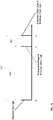
- Period of time "P1" may be a pre-determined period of time or a dynamically determined period of time determined, for example, based on CGM data, other physiological data, and/or other input data or other physiological data.
- Green light 1036 and corresponding symbol 1037 indicate to the user that it is safe to dose, green light 1036 is illuminated at time “t 1 ,” only after time period "P1" has elapsed, and only until a subsequent dose is logged. With green light 1036 illuminated, a dose is logged when cap 110 is removed from pen 20 ( FIG. 4 ), assuming any other criteria, e.g., the length of time cap 110 is removed, the other factors, etc. as detailed above, are met.
- red light 1032 and corresponding symbol 1033 indicate to the user that it is not safe to dose, red light 1032 is illuminated at time “t 0 " and remains illuminated throughout period "P2" until time “t 2 .”
- Period of time "P2" may be pre-determined or dynamically determined. In aspects, if cap 110 is removed from pen 20 ( FIG. 4 ) while red light 1032 is illuminated, an assumption is made that a dose was not taken regardless of the length of time cap 110 is removed, the other factors, etc. and, thus, no dose is logged. This assumption may be overridden based on other factors, input information, sensed data, etc.
- red light 1032 is extinguished at time “t 2 " and yellow light 1034 is illuminated.
- Yellow light 1034 indicating that the user should proceed with caution because it is not recommended to dose but may be acceptable, remains illuminated for the duration of time period "P3" until time "t 1 ,” after which yellow light 1034 is extinguished and green light 1036 is illuminated until the next dose is logged.
- a dose is logged when cap 110 is removed from pen 20 ( FIG. 4 ), assuming any other criteria, e.g., the length of time cap 110 is removed, the other factors, etc. as detailed above, are met.
- the criteria for logging a dose upon removal of cap 20 with yellow light 1034 illuminated may differ from the criteria for logging a dose upon removal of cap 20 with green light 1036 illuminated.
- control implementation of lights 1032, 1034, 1036 describes the illumination and extinguishing of lights 1032, 1034, 1036 in an activated condition
- the control implementation may not be activated at all times but, rather, may have a dormant condition. That is, in the dormant condition, all lights may be extinguished, e.g., to conserve battery and inhibit distraction.
- the above control implementation may be activated from the dormant condition when motion is sensed, indicating that pen 20 ( FIG. 4 ) with cap 110 thereon is being manipulated, e.g., picked up, removed from the user's pocket, etc.
- control implementation may additionally or alternatively be activated from the dormant condition when cap 110 is removed from pen 20 ( FIG. 4 ).
- control implementation may switch between the activated and dormant conditions based upon the time of the day, the user's schedule or location (e.g., obtained from connected devices), based on physiological feedback data (e.g., obtained from connected devices), etc.
- control implementation may be set to or may always remain in the activated condition.
- user interface 130 may be provided on body 22 of pen 20 (see FIGS. 3A and 3B ) to convey information to the user similarly as detailed above.
- pen 20 may be configured to sense an amount of dose selected and/or dispensed, and/or to communicate with a connected device, e.g., cap 110, smartphone 30 running health management application 40 ( FIG. 1A )), etc., such as, for example, detailed in U.S. Patent No. 9,672,328 , issued on June 6, 2017 and titled "Medicine Administering System Including Injection Pen and Companion Device," the entire contents of which are hereby incorporated herein by reference.
- the described functional and/or operational aspects may be implemented in hardware, software, firmware, or any combination thereof. If implemented in software, the functions may be stored as one or more instructions or code on a computer-readable medium and executed by a hardware-based processing unit.
- Computer-readable media may include non-transitory computer-readable media, which corresponds to a tangible medium such as data storage media (e.g., RAM, ROM, EEPROM, flash memory, or any other medium that can be used to store desired program code in the form of instructions or data structures and that can be accessed by a computer).
- processors such as one or more digital signal processors (DSPs), general purpose microprocessors, application specific integrated circuits (ASICs), field programmable logic arrays (FPGAs), or other equivalent integrated or discrete logic circuitry.
- DSPs digital signal processors
- ASICs application specific integrated circuits
- FPGAs field programmable logic arrays
Abstract
An accessory for use with a medicine delivery device includes a body configured to attach to a medicine delivery device and a user interface disposed on the body and configured to communicate information to a user. In aspects, the user interface includes first and second lights configured to be selectively illuminated and a first symbol associated with the first light. The first light and the first symbol together indicate an action to be performed when the first light is illuminated. In aspects, the user interface includes red, yellow, and green lights configured to be illuminated in sequential time periods after a dose using the medicine delivery device.
Description
- The present disclosure is related to medicine administration and tracking and, more specifically, to accessory devices, systems, and methods for medicine administration and tracking.
- Diabetes mellitus ("diabetes") is a metabolic disease associated with high blood sugar due to insufficient production or use of insulin by the body. Diabetes affects hundreds of millions of people and is among the leading causes of death globally. Diabetes has been categorized into three types: type 1, type 2, and gestational diabetes. Type 1 diabetes is associated with the body's failure to produce sufficient levels of insulin for cells to uptake glucose. Type 2 diabetes is associated with insulin resistance, in which cells fail to use insulin properly. Gestational diabetes can occur during pregnancy when a pregnant woman develops a high blood glucose level. Gestational diabetes often resolves after pregnancy; however, in some cases, gestational diabetes develops into type 2 diabetes.
- Various diseases and medical conditions, such as diabetes, require a user to self-administer doses of medicine. When administering a liquid medicine by injection, for example, the appropriate dose amount is set and then dispensed by the user, e.g., using a syringe, a medicine delivery pen, or a pump. Regardless of the particular device utilized for injecting the liquid medicine, it is important track medicine dosed and facilitate a user's compliance with a dosing regime, particularly for managing lifelong or chronic conditions like diabetes.
- Provided in accordance with aspects of the present disclosure is an accessory for use with a medicine delivery device. The accessory includes a body configured to attach to a medicine delivery device and a user interface disposed on the body and configured to communicate information to a user. The user interface includes first and second lights configured to be selectively illuminated and a first symbol associated with the first light. The first light and the first symbol together indicate an action to be performed when the first light is illuminated.
- In an aspect of the present disclosure, the first light is a green light and the second light is a red light.
- In another aspect of the present disclosure, the first light is a green light and the first symbol represents at least a portion of the medicine delivery device such that, when the green light is illuminated, the action to be performed of using the medicine delivery device is indicated.
- In still another aspect of the present disclosure, the user interface further includes a second symbol associated with the second light. In such aspects, the second light and the second symbol together provide an indication to the user. More specifically, the second light may be a red light and the second symbol may be a stop symbol such that, when the red light is illuminated, the indication to the user is to stop and not proceed with using the medicine delivery device.
- In yet another aspect of the present disclosure, the body is configured to releasably attached to the medicine delivery device. In such aspects, the body may be a cap configured to releasably cover a dispensing end of the medicine delivery device.
- In still yet another aspect of the present disclosure, the accessory further includes at least one detector disposed within the body and configured to detect at least one of attachment of the cap with the medicine delivery device or detachment of the cap from the medicine delivery device.
- In another aspect of the present disclosure, the user interface further includes a third light configured to be selectively illuminated. In such aspects, the first light may be a green light indicating it is safe to use the medicine delivery device to dose, the second light may be a red light indicating it is not safe to use the medicine delivery device to dose, and/or the third light may be a yellow light indicating the user to proceed with caution.
- Another accessory for use with a medicine delivery device in accordance with the present disclosure includes a body configured to attach to a medicine delivery device, an electronics unit disposed within the body, and a user interface disposed on the body in communication with the electronics unit. The electronics unit is configured to at least one of receive or determine, with respect to a prior dose at time t0, a first time t1 after which it is safe to dose and a second time t2 before which it is not safe to dose. The user interface includes a green light, a red light, and a yellow light. The electronics unit is configured to control the user interface to illuminate the red light between time t0 and time t2, extinguish the red light and illuminate the yellow light at time t2, maintain the yellow light from time t2 to time t1, and extinguish the yellow light and illuminate the green light at time t1.
- In an aspect of the present disclosure, the electronics unit is further configured to control the user interface to maintain the green light from time t1 until a subsequent dose is logged.
- In another aspect of the present disclosure, times t0, t1, and t2 are relative times (e.g., where t0 = 0 or a start of a count-up timer) or clock times (e.g., actual times on a 12hr or 24hr clock).
- In still another aspect of the present disclosure, the body is a cap configured to releasably cover a dispensing end of the medicine delivery device. In such aspects, at least one detector may be disposed within the body and configured to detect at least one of attachment of the cap with the medicine delivery device or detachment of the cap from the medicine delivery device.
- In yet another aspect of the present disclosure, the electronics unit is configured to determine or receive a determination that a dose from the medicine delivery device has occurred based at least upon at least one of an attachment of the cap or a detachment of the cap.
- In still yet another aspect of the present disclosure, the determination that a dose from the medicine delivery device has occurred is further based upon which light is illuminated. More specifically, no determination that a dose from the medicine delivery device has occurred may be made despite the at least one of attachment of the cap or detachment of the cap when the red light is illuminated. Alternatively or additionally, the determination that a dose from the medicine delivery device has occurred may be made based upon the at least one of attachment of the cap or detachment of the cap and other criteria when either the green light or the yellow light is illuminated. In aspects, the criteria when the green light is illuminated are different from the criteria when the yellow light is illuminated.
- Further disclosed herein is an accessory for use with a medicine delivery device includes a body configured to attach to a medicine delivery device and a user interface disposed on the body and configured to communicate information to a user, wherein the user interface includes first and second lights configured to be selectively illuminated and a first symbol associated with the first light, wherein the first light and the first symbol together indicate an action to be performed when the first light is illuminated, wherein the user interface includes red, yellow, and green lights configured to be illuminated in sequential time periods after a dose using the medicine delivery device.
-
-
FIG. 1A is a schematic illustration of a medicine administration and tracking system provided in accordance with the present disclosure including a medicine delivery device, an accessory attached to the medicine delivery device, a computing device, and, in aspects, a sensor device and/or a data processing system; -
FIG. 1B is a block diagram of one configuration of the computing device of the system ofFIG. 1A in accordance with the present disclosure; -
FIG. 2 is a perspective view of the medicine delivery device ofFIG. 1A ; -
FIGS. 3A and 3B are side, partial longitudinal, cross-sectional views of the medicine delivery device ofFIG. 2 with the medicine cartridge in a full condition and the medicine cartridge in a partially emptied condition, respectively; -
FIG. 4 is a perspective view of the medicine delivery device ofFIG. 2 including an accessory device in accordance with the present disclosure coupled thereto; -
FIG. 5 is an enlarged, perspective view of the accessory device ofFIG. 4 ; -
FIGS. 6-9 are longitudinal, cross-sectional views of the accessory device ofFIG. 4 including various different detectors in accordance with the present disclosure; -
FIG. 10 is a top view of the accessory device ofFIG. 4 including a user interface in accordance with the present disclosure; and -
FIG. 11 is graphical representation of a timeline for dose recommendation indicators in accordance with the present disclosure. -
FIG. 1A illustrates a medicine administration andtracking system 10 provided in accordance with the present disclosure including amedicine delivery device 20, acomputing device 30 running ahealth management application 40, and anaccessory device 110 configured to mechanically couple tomedicine delivery device 20 and to wirelessly communicate withcomputing device 30 and/or other devices part of or connected tosystem 10.System 10, in aspects, further includes adata processing system 50 and/or asensor device 60. -
Medicine delivery device 20 is detailed and illustrated herein as a medicine delivery pen, although any other suitable medicine delivery device may be provided such as, for example, a syringe, a pump, etc.Pen 20, described in greater detail below, is operable to select, set, and/or dispense a dose of medicine, e.g., a dose of insulin. Pen 20 may be configured as a disposable device, e.g., whereinpen 20 is discarded once emptied of medicine, or a reusable device configured to enable refilling and/or replacement of a medicine cartridge thereof. Although referred to herein in the singular, it is understood that reference topen 20 is not limited tosingle pen 20 but may apply tomultiple pens 20 with whichaccessory device 110 is utilized. -
Computing device 30 is detailed and illustrated herein as a smartphone, although any other suitable computing device may be provided such as, for example, a tablet, a wearable computing device (e.g., a smart watch, smart glasses, etc.), a laptop and/or desktop computer, a smart television, a network-based server computer, etc. -
Accessory device 110 is detailed herein as a cap for selectively covering a dispensing end ofpen 20, although other suitableaccessory devices 110 configured, for example, to mechanically engage abody 22 ofpen 20, facilitate holdingpen 20 on a support surface (e.g., a table), facilitate retainingpen 20 during transport (e.g., in a user's pocket or bag), etc. are also contemplated. -
Health management application 40 is paired withaccessory device 110, which may be a prescription-only medical device for use with medicine delivery devices, e.g.,pen 20, viasmartphone 30, although other suitable configurations are also contemplated. In aspects, the pairing ofsmartphone 30 withaccessory device 110 at least partially unlockshealth management application 40 to enable the user to utilize some or all features ofhealth management application 40, e.g., according to the user's prescription. Thus, the act of pairing can unlock and enable the functionality ofhealth management application 40 and/or system 10 (including accessory device 110), while health management application 40 (and/or system 10) may provide only limited features in the absence of pairing withaccessory device 110. -
Health management application 40 ofsmartphone 30, in aspects, can monitor and/or control functionalities ofaccessory device 110 and provide a dose calculator module and/or decision support module that can calculate and recommend a dose of medicine for the user to administer usingpen 20.Health management application 40 provides a user interface, on the user interface ofsmartphone 30, to allow a user to manage health-related data. For example,health management application 40 can be configured to control some functionalities ofaccessory device 110 and/or to provide an interactive user interface to allow a user to manage settings ofaccessory device 110 and/or settings forsmartphone 30 that can affect the functionality ofsystem 10.Smartphone 30 can additionally or alternatively be used to obtain, process, and/or display contextual data that can be used to relate to the health condition of the user, including the condition for whichpen 20 is used to treat. For example,smartphone 30 may be operable to track the location of the user; physical activity of the user including step count, movement distance and/or intensity, estimated calories burned, and/or activity duration; and/or interaction pattern of the user withsmartphone 30. In aspects,health management application 40 can aggregate and process the contextual data to generate decision support outputs, e.g., on the user interface and/or onaccessory device 110, to guide and aid the user in monitoring their condition, usingpen 20, and/or managing their behavior to promote treatment and better health outcomes. - In aspects,
system 10 further includes adata processing system 50 in communication withaccessory device 110 and/orsmartphone 30.Data processing system 50 can include one or more computing devices in a computer system and/or communication network accessible via the internet, e.g., including servers and/or databases in the cloud.System 10 can additionally or alternatively includesensor device 60 to monitor one or more health metrics and/or physiological parameters of the user. Examples of health metric and physiological parameter data monitored bysensor device 60 include analytes (e.g., glucose), heart rate, blood pressure, user movement, temperature, etc.Sensor device 60 may be a wearable sensor device such as a continuous glucose monitor (CGM) to obtain transcutaneous or blood glucose measurements that are processed to produce continuous glucose values. For example, the CGM can include a glucose processing module implemented on a stand-alone display device and/or implemented onsmartphone 30, which processes, stores, and displays the continuous glucose values for the user. Such continuous glucose values can be utilized byhealth management application 40, for example, for displaying health data, in dose calculation and/or decision support, etc. -
FIG. 1B illustratessmartphone 30 of system 10 (FIG. 1A ) including adata processing unit 31, awireless communications unit 35, and adisplay unit 36.Data processing unit 31 includes aprocessor 32 to process data, amemory 33 in communication with theprocessor 32 to store data, and an input/output unit (I/O) 34 to interfaceprocessor 32 and/ormemory 33 to other modules, units, and/or devices ofsmartphone 30 and/or external devices.Processor 32 can include a central processing unit (CPU) or a microcontroller unit (MCU).Memory 33 can include and store processor-executable code, which when executed byprocessor 32, configures thedata processing unit 31 to perform various operations, e.g., such as receiving information, commands, and/or data, processing information and data, and transmitting or providing information/data to another device. In aspects,data processing unit 31 can transmit raw or processed data to data processing system 50 (FIG. 1A ). To support various functions ofdata processing unit 31,memory 33 can store information and data, such as instructions, software, values, images, and other data processed or referenced byprocessor 32. For example, various types of Random Access Memory (RAM) devices, Read Only Memory (ROM) devices, Flash Memory devices, and other suitable storage media can be used to implement storage functions ofmemory 33. I/O 34 ofdata processing unit 31 can interfacedata processing unit 31 withwireless communications unit 35 to utilize various types of wired or wireless interfaces compatible with typical data communication standards, for example, which can be used in communications ofdata processing unit 31 with other devices such aspen 20, via a wireless transmitter/receiver (Tx/Rx), e.g., including, but not limited to, Bluetooth, Bluetooth low energy, Zigbee, IEEE 802.11, Wireless Local Area Network (WLAN), Wireless Personal Area Network (WPAN), Wireless Wide Area Network (WWAN), WiMAX, IEEE 802.16 (Worldwide Interoperability for Microwave Access (WiMAX)), 3G/4G/LTE cellular communication methods, NFC (Near Field Communication), and parallel interfaces. I/O 34 ofdata processing unit 31 can also interface with other external interfaces, sources of data storage, and/or visual or audio display devices, etc. to retrieve and transfer data and information that can be processed byprocessor 32, stored inmemory 33, and/or exhibited on an output unit ofsmartphone 30 and/or an external device. For example,display unit 36 ofsmartphone 30 can be configured to be in data communication withdata processing unit 31, e.g., via I/O 34, to provide a visual display, an audio display, and/or other sensory display that produces the user interface of the health management application 40 (FIG. 1A ). In some examples,display unit 36 can include various types of screen displays, speakers, or printing interfaces, e.g., including but not limited to, light emitting diode (LED), or liquid crystal display (LCD) monitor or screen, cathode ray tube (CRT) as a visual display; audio signal transducer apparatuses as an audio display; and/or toner, liquid inkjet, solid ink, dye sublimation, inkless (e.g., such as thermal or UV) printing apparatuses, etc. -
Smartphone 30 can receive dose and related information (e.g., which can include time information, dose setting information, and/or dose dispensing information) via manual entry by the user and/or automatically from a connected tracking device (within or associated withpen 20,accessory device 110, and/or other connected device(s)). Upon receipt of the dose and related information,smartphone 30 stores the information inmemory 33, e.g., which can be included among a list of doses or dosing events. In aspects, via the user interface associated withhealth management application 40,smartphone 30 allows the user to browse a list of previous doses, to view an estimate of current medicine active in the user's body (medicine on board, e.g., insulin on board) based on calculations performed byhealth management application 40, and/or to utilize a dose calculation module to assist the user regarding dose setting information on the size of the next dose(s) to be delivered. For example, the user may enter carbohydrates to be eaten and current blood sugar (which alternatively may be obtained directly from sensor device 60 (FIG. 1A )), andhealth management application 40 may already know insulin on board. Using these parameters, a suggested medicine dose (e.g., a recommended insulin dose), calculated by the dose determination module, may be determined. - Referring to
FIGS. 2 ,3A, and 3B ,pen 20 includes abody 22 configured to contain amedicine cartridge 23, e.g., an insulin cartridge.Pen 20 further includes adose dispensing mechanism 24 to dispense (e.g., deliver) medicine contained inmedicine cartridge 23 out of pen 20 (e.g., through needle 29) and adose setting mechanism 25 to enable the selection and/or setting of a dose of medicine to be dispensed. - In aspects, in order to operate
pen 20, the user first sets e.g., dials, a dose using adose knob 26a ofdose setting mechanism 25. For example, the dose may be adjusted up or down to achieve a desired dose amount prior to administration of the dose by rotatingdose knob 26a in an appropriate direction. Adose indicator window 26d throughbody 22 is provided to enable a user to view the units set viadose knob 26a. Once the appropriate dose has been set, the user applies a force against adose dispensing button 26b ofdose dispensing mechanism 24 to begin dispensing. More specifically, to begin dispensing, the user presses against the portion ofdose dispensing button 26b that protrudes frombody 22 ofpen 20 to thereby drive a drivingelement 26c, e.g., adrive screw 26c, ofdose dispensing mechanism 24 against an abutment, e.g.,piston 23b, ofmedicine cartridge 23 to dispense an amount of medicine fromcartridge 23 throughneedle 29 into the user in accordance with the dose amount set bydose setting mechanism 25, e.g.,dose knob 26a, during setting.Needle 29 may be integrated withpen 20 and/orcartridge 23 or may be removable and replaceable frompen 20 and/orcartridge 23. -
Dose dispensing mechanism 24 ofpen 20 can include a manually powered mechanism (user powered and/or mechanically biased), a motorized mechanism, or an assisted mechanism (e.g., a mechanism that operates partly on manual power and partly on motorized power). Regardless of the particular configuration of thedose dispensing mechanism 24, as noted above, when a force (e.g., a manual force, electrically-powered motor force, or combinations thereof) is applied to drivescrew 26c ofdose dispensing mechanism 24,drive screw 26c turn provides a force to urge medicine frommedicine cartridge 23 to deliver the set or dialed dose. In aspects, dose dispensingmechanism 24 can be operated such that rotation and/or translation of the driving element, e.g., drivescrew 26c, is facilitated by a variable tension spring or a variable speed motor to inject the dose over a specific time frame (e.g., 1 s, 5 s, etc.) to help reduce the pain of dosing and/or for other purposes. -
Medicine cartridge 23 includes avial body 23a defining an interior volume configured to retain a volume of medicine, e.g., insulin, therein, and apiston 23b sealingly and slidingly disposed withinvial body 23a such that displacement ofpiston 23b withinvial body 23a towards the dispensing end ofvial body 23a forces medicine from the interior volume through dispensing opening 23c ofcartridge 23 andneedle 29 for injection into the user. - The rotation of the
dose knob 26a during actuation drives (direct or indirect) rotation ofdrive screw 26c which rides within a nut (not explicitly shown) which is fixed tobody 22 ofpen 20. In this manner, rotation ofdrive screw 26c also results in translation ofdrive screw 26c (due to the pitched threading ofdrive screw 26c) towardsmedicine cartridge 23 to thereby drivepiston 23b throughvial body 23a to expel medicine frommedicine cartridge 23 for injection into the user. The extent to whichdose knob 26a extends frombody 22 ofpen 20 prior to actuation (which corresponds to the selected dose to be injected) defines the maximum amount of rotation ofdose knob 26a and, thus, drivescrew 26c during actuation; as such, the amount of medicine expelled frommedicine cartridge 23 during actuation cannot exceed the selected dose amount. - Turning to
FIGS. 4-6 , as noted above, accessory device 100 may be configured as acap 110 configured to selectively mechanically engagepen 20 to cover a dispensing end thereof, with or without needle 29 (FIGS. 3A and 3B ) attached to pen 20.Cap 110 includes abody 112 defining ahousing 116, a spring-loaded (e.g., via spring 138)slider 118 slidably disposed withinhousing 116, and a coupler adapter 114 (e.g., an appropriate coupler adapter 114 selected from a set of coupler adapters 114) releasably engageable withslider 118 and configured to enable use ofcap 110 with various differently sized, shaped, and/or otherwise configured pens 20. Adapter 114 is configured to receive and engagepen 20 when the dispensing end ofpen 20 is inserted intohousing 116 to thereby retaincap 110 in engagement aboutpen 20 enclosing the dispensing end ofpen 20 withinhousing 116. -
Cap 110 further includes anelectronics unit 120 that includes a detector (e.g., detection switch 122), abattery 124, a printed circuit board assembly (PCBA) 126, and auser interface 130.PCBA 126 may include a processor, a real-time clock, a storage module, and/or a communications module for wireless data transfer (e.g., via Bluetooth, WiFi, cellular network, and/or other suitable wireless communication protocol) to and/or from smartphone 30 (FIGS. 1A and 1B ), although it is also contemplated that some of these components may be separate fromPCBA 126 or omitted entirely.Electronics unit 120 is disposed (and, in aspects, sealed) within a cavity defined withinbody 112 ofcap 110. - A
cover 150 ofbody 112 encloses (and, in aspects, seals) the cavity and, thus,electronics unit 120 therein. Where a seal is provided, it may be hermetic to inhibit damage toelectronics 120 from exposure to fluids, debris, etc. The output device(s) producinguser interface 130 may form part ofcover 150 to enable output (e.g., visual, audible, or other sensory output) fromuser interface 130, and/or cover 150 may include openings or other features to enable output of the output devices(s) producinguser interface 130 oncover 150. The output device(s) producinguser interface 130 may include a display screen, one or more LED's or other visual indicators, a speaker or other audio output device, a haptic feedback device, and/or other suitable user interface features configured to communicate information to a user. - When
pen 20 is inserted intocap 110,pen 20 urgesslider 118 to translate against the bias ofspring 138 and interact with adeflectable arm 137 associated withdetection switch 122 that extends into the travel path ofslider 118. More specifically, thedeflectable arm 137 ofdetection switch 122 may be biased to extend into the travel path (in the absence of slider 118) and to deflect out of the travel path in response to contact by and urging fromslider 118 asslider 118 is translated withinhousing 116, e.g., under urging from the insertion ofpen 20 intocap 110. Sufficient deflection ofdeflectable arm 137 closes (or opens)detection switch 122 such that a signal is detected byelectronics unit 120 indicating thatpen 20 has been inserted intocap 110. On the other hand, whenpen 20 is removed fromcap 110,slider 118 translates, under the bias ofspring 138 back to its initial position, spaced-apart fromdeflectable arm 137. As such,deflectable arm 137 is returned to its initial, biased position extending into the travel path. Asdeflectable arm 137 is returned to this initial, biased position,detection switch 122 is opened (or closed) such that a signal is detected byelectronics unit 120 indicating thatpen 20 has been removed fromcap 110. - Additional aspects and features of
cap 110, configured for use in whole or in part in accordance with the aspects and features of the present disclosure (in whole or in part) can be found inU.S. Patent Application Pub. No. 2020/0327973, filed on April 13, 2020 and titled "Intelligent Accessories for Medicine Dispensing Device," the entire contents of which are hereby incorporated herein by reference. - Continuing with reference to
FIGS. 4-6 , the signals indicating thatpen 20 has been inserted into and/or removed fromcap 110 can be utilized, e.g., by the processor ofelectronics unit 120 and/or via health management application 40 (FIG. 1A ), to determine whether a dispensing event has occurred and, in aspects, what type of dispensing event, e.g., a priming event or an injection event, has occurred. For example, a dispensing event may be determined: based on removal ofcap 110, based on replacement ofcap 110, or based on removal ofcap 110 without replacement for a defined period of time. The type of dispensing event may be determined based on the length oftime cap 110 is removed, other factors, and/or other input data. - Referring to
FIG. 7 , in aspects, the detector may be anon-contact sensor 722 configured to detect movement of slider 118 (or a portion thereof, which may include adetectable element 737 to facilitate detection) into or out of approximation withsensor 722 to thereby enable detection of insertion or removal, respectively, of pen 20 (FIG. 4 ) to/fromcap 110. For example,non-contact sensor 722 may be a hall effect sensor (whereindetectable element 737, if provided, is a magnetic element, or whereslider 118 itself is a magnetic element), an optical sensor (whereindetectable element 737, if provided, is reflective, provides a detectable color, provides a detectable pattern, etc., or whereslider 118 itself provides the same), a capacitive sensor (whereindetectable element 737, if provided, is electrically-conductive, or whereslider 118 or other portion thereof is electrically-conductive), In aspects,non-contact sensor 722 is sealed, e.g., together withelectronics unit 120 or separately therefrom. -
Non-contact sensor 722, further still, may be an accelerometer or other suitable vibration sensor configured to sense vibrations associated with movement ofslider 118 and/or movement of pen 20 (FIG.4 ) during insertion and engagement of pen 20 (FIG. 4 ) withincap 110 and/or disengagement and removal of pen (FIG. 4 ) fromcap 110. Likewise,non-contact sensor 722 may be an audio sensor, e.g., a microphone, configured to sense sounds associated with movement ofslider 118 and/or movement of pen 20 (FIG.4 ) during insertion and engagement of pen 20 (FIG. 4 ) withincap 110 and/or disengagement and removal of pen (FIG. 4 ) fromcap 110. - Other suitable locations for
sensor 722 are also contemplated depending upon a particular purpose such as, for example, to sense movement and/or other properties of spring 738 rather thanslider 118. In aspects wherein spring 738 is a coil spring, for example,sensor 722 may be configured to sense movement, e.g., approximation or spacing, of the rungs of spring 738, e.g., optically, or may be configured to sense an amount of compression of spring 738, e.g., electrically based on a change in capacitance of spring 738 as it is compressed or extended. As movement of spring 738 is related to whether pen 20 (FIG. 4 ) is inserted or removed fromcap 110, sensing movement of spring 738 can thus provide similar information as detailed above with respect toslider 118. - With reference to
FIGS. 8 and9 , in aspects, rather than providing slider 118 (and/or spring 738) to enable detection of insertion and/or removal ofpen 20, detector may include asensor interior cavity 823 defined byhousing 116 ofcap 110 to enable detection of the insertion and/or removal ofpen 20. Referring in particular toFIG. 8 ,sensor 822 may be configured to sense the presence or absence of pen 20 (or a portion thereof) withininterior cavity 823, and may accomplish this by being configured as an optical sensor, a vibration sensor, an audio sensor, a magnetic sensor (where a portion ofpen 20 is magnetic), a capacitive sensor (where a portion ofpen 20 is electrically-conductive), a moisture sensor (sensing medicine onneedle 29 or a dispensing end of pen 20), etc. Referring in particular toFIG. 9 , in aspects,sensor 922 may include asecond component 937 that cooperates withsensor 922 to facilitate detection.Second component 937 may be disposed oppositesensor 922 acrosscavity 823 and may be, for example, a reflector (for an optical sensor), receiver (e.g., whereinsensor 922 is a transmitter), or other reference component to facilitatesensor 922 detecting whetherpen 20 is disposed withincavity 823 or removed therefrom based on whether a signal is capable of being communicated betweensensor 922 andsecond component 937. - Continuing with reference to
FIGS. 8 and9 , in aspects,sensor 822 and/orsensor 922 may be configured, in addition or as an alternative to detecting the presence or absence ofpen 20, to determine one or more features ofpen 20 and/or the medicine or medicine cartridge 23 (FIGS. 3A and 3B ). For example,sensor 822 and/orsensor 922 may be configured to detect a size, shape, feature, or other physical characteristic of the exterior ofpen 20, which can be communicated to enable determination of a manufacturer and/or type of pen 20 (or cartridge 23 (FIGS. 3A and 3B ) therein), e.g., via health management application 40 (FIG. 1A ). As another example,sensor 822 and/orsensor 922 may be configured to detect an amount and/or property (clarity, for example), of medicine, e.g., insulin, inpen 20, to enable communication of the same to health management application 40 (FIG. 1A ). - Turning to
FIG. 10 , as noted above,cap 110 includes auser interface 130 to enable the output of information to a user.User interface 130 may be disposed oncover 150 ofbody 112 ofcap 110 or may be otherwise disposed, e.g., at another location onbody 112. In aspects,cap 110 is configured to independently determine and output and/or to communicate with health management application 40 (FIG. 1A ) to enable output of relevant information to the user viauser interface 130 ofcap 110. For example,user interface 130 may provide an output to the user to inform the user whether it is safe to dose. In aspects,user interface 130 is a display screen that enables display and, in aspects, input (e.g., via touch-screen functionality), of information such as, for example, by displaying a version of health management application 40 (FIG. 1A ). However, the power available foruser interface 130 may be limited in an effort to conserve battery and, thus, in other aspects,user interface 130 may include twolights lights symbology - In aspects, the
lights - To obviate the above confusion,
lights least lights 1032, 1036 (whether only lights 1032, 1036 are provided or all threelights symbology symbol 1037 is positioned adjacent green light 1036 (or otherwise associated therewith such as, for example, wheresymbol 1037 is overlayed or otherwise positioned relative togreen light 1036 such thatsymbol 1037 is illuminated whengreen light 1037 is illuminated).Symbol 1037 indicates the action to be taken; that is, the action that it is safe to proceed when thegreen light 1036 is illuminated.Symbol 1037 may be an image or other representation of a needle (as shown), a syringe, an injection pen, an amount of medicine, or other suitable symbol indictive of the delivery of medicine to the user.Symbol 1033 is positioned adjacent (or otherwise associated with)red light 1032 and indicates the action to be taken; that is, "stop" or "do not proceed" when thered light 1032 is illuminated.Symbol 1033 may be an image or other representation to "stop" such as, for example, a stop hand signal (as shown), a stop sign, or other suitable symbol indicating to the user to stop or take no action because it is not safe to dose. In configurations whereyellow light 1034 is provided,symbol 1035 is positioned adjacent (or otherwise associated with)yellow light 1034 and provides an indication of caution, e.g., via a caution sign or other suitable symbol, thus indicating the user to proceed with caution because it is not recommended to dose but may acceptable. - Control of, e.g., selective illumination of,
lights FIG. 6 ) based on determinations made by electronics unit 120 (FIG. 6 ) and/or from a connected device, e.g.,smartphone 30 running health management application 40 (FIG. 1A )). For example, health management application 40 (FIG. 1A ) may communicate to electronics unit 120 (FIG. 6 ) of cap 110 a log of one or more prior injections, an interval between doses, and/or a schedule of doses, etc. to enable electronics unit 120 (FIG. 6 ) to illuminate theappropriate light FIG. 6 ) may determine when a dose occurs (as detailed above, for example, or in any other suitable manner), determine an interval between doses, and, based thereon, illuminate theappropriate light FIG. 1A ) and/or electronics unit 120 (FIG. 6 ) may additionally or alternatively utilize CGM data, other physiological data, and/or other input data (e.g., meal data, exercise data, etc.), to determine whether it is safe to dose. A control implementation oflights FIG. 11 , although other suitable control implementations are also contemplated. - With additional reference to
FIG. 11 , following each dose, e.g., a dose at time "t0," a time after which it is safe to dose is set as "t1," thus defining a time period "P1," wherein P1 = t1 - t0. Period of time "P1" may be a pre-determined period of time or a dynamically determined period of time determined, for example, based on CGM data, other physiological data, and/or other input data or other physiological data. Asgreen light 1036 andcorresponding symbol 1037 indicate to the user that it is safe to dose,green light 1036 is illuminated at time "t1," only after time period "P1" has elapsed, and only until a subsequent dose is logged. Withgreen light 1036 illuminated, a dose is logged whencap 110 is removed from pen 20 (FIG. 4 ), assuming any other criteria, e.g., the length oftime cap 110 is removed, the other factors, etc. as detailed above, are met. - In addition to the "safe to dose" time "t1," there is a time "t2" before which it is not safe to dose, thus defining a second period of time "P2," wherein P2 = t2 - t0. As
red light 1032 andcorresponding symbol 1033 indicate to the user that it is not safe to dose,red light 1032 is illuminated at time "t0" and remains illuminated throughout period "P2" until time "t2." Period of time "P2" may be pre-determined or dynamically determined. In aspects, ifcap 110 is removed from pen 20 (FIG. 4 ) whilered light 1032 is illuminated, an assumption is made that a dose was not taken regardless of the length oftime cap 110 is removed, the other factors, etc. and, thus, no dose is logged. This assumption may be overridden based on other factors, input information, sensed data, etc. - In aspects where no
yellow light 1034 is provided, t1 = t2 and P1 = P2. However, it has been found that there may be a time period "P3" defined between times "t2" and "t1" wherein, while it is not recommended to dose, it may be acceptable to dose in certain circumstances, for example, where the user is not able to dose for an extended length of time after expiration of time period "P1," e.g., due to a social commitment, work commitment, personal reason, or any other reason. Time period "P3" may be pre-determined or dynamically determined, and is defined in relation to "P1" and "P2" according to the equation P1 = P2 + P3. - In aspects where time period "P3" is utilized,
red light 1032 is extinguished at time "t2" andyellow light 1034 is illuminated. Yellow light 1034, indicating that the user should proceed with caution because it is not recommended to dose but may be acceptable, remains illuminated for the duration of time period "P3" until time "t1," after whichyellow light 1034 is extinguished andgreen light 1036 is illuminated until the next dose is logged. With yellow light 1034 illuminated, a dose is logged whencap 110 is removed from pen 20 (FIG. 4 ), assuming any other criteria, e.g., the length oftime cap 110 is removed, the other factors, etc. as detailed above, are met. In aspects, the criteria for logging a dose upon removal ofcap 20 with yellow light 1034 illuminated may differ from the criteria for logging a dose upon removal ofcap 20 withgreen light 1036 illuminated. - Although the above control implementation of
lights lights FIG. 4 ) withcap 110 thereon is being manipulated, e.g., picked up, removed from the user's pocket, etc. As another example, the above control implementation may additionally or alternatively be activated from the dormant condition whencap 110 is removed from pen 20 (FIG. 4 ). In other aspects, in addition or as an alternative to the above, the control implementation may switch between the activated and dormant conditions based upon the time of the day, the user's schedule or location (e.g., obtained from connected devices), based on physiological feedback data (e.g., obtained from connected devices), etc. In other aspects, the control implementation may be set to or may always remain in the activated condition. - In aspects, rather than providing
user interface 130 oncap 110,user interface 130 may be provided onbody 22 of pen 20 (seeFIGS. 3A and 3B ) to convey information to the user similarly as detailed above. In such aspects, or any other aspects detailed herein, pen 20 (seeFIGS. 3A and 3B ) may be configured to sense an amount of dose selected and/or dispensed, and/or to communicate with a connected device, e.g.,cap 110,smartphone 30 running health management application 40 (FIG. 1A )), etc., such as, for example, detailed inU.S. Patent No. 9,672,328 - The various aspects and features disclosed herein may be combined in different combinations than the combinations specifically presented in the description and accompanying drawings. It should also be understood that, depending on the example, certain acts or events of any of the processes or methods described herein may be performed in a different sequence, may be added, merged, or left out altogether (e.g., all described acts or events may not be necessary to carry out the techniques). In addition, while certain aspects of this disclosure are described as being performed by a single module or unit for purposes of clarity, it should be understood that the techniques of this disclosure may be performed by a combination of units or modules associated with, for example, a medical device.
- In one or more examples, the described functional and/or operational aspects may be implemented in hardware, software, firmware, or any combination thereof. If implemented in software, the functions may be stored as one or more instructions or code on a computer-readable medium and executed by a hardware-based processing unit. Computer-readable media may include non-transitory computer-readable media, which corresponds to a tangible medium such as data storage media (e.g., RAM, ROM, EEPROM, flash memory, or any other medium that can be used to store desired program code in the form of instructions or data structures and that can be accessed by a computer).
- Instructions may be executed by one or more processors, such as one or more digital signal processors (DSPs), general purpose microprocessors, application specific integrated circuits (ASICs), field programmable logic arrays (FPGAs), or other equivalent integrated or discrete logic circuitry. Accordingly, the term "processor" or "processing unit" as used herein may refer to any of the foregoing structure or any other physical structure suitable for implementation of the described techniques. Also, the techniques could be fully implemented in one or more circuits or logic elements.
- While several aspects of the present disclosure have been detailed above and are shown in the drawings, it is not intended that the disclosure be limited thereto, as it is intended that the disclosure be as broad in scope as the art will allow and that the specification be read likewise. Therefore, the above description and accompanying drawings should not be construed as limiting, but merely as exemplifications of particular aspects. Those skilled in the art will envision other modifications within the scope and spirit of the claims appended hereto.
- Further disclosed herein is the subject-matter of the following clauses:
- 1. An accessory for use with a medicine delivery device, the accessory comprising:
- a body configured to attach to a medicine delivery device; and
- a user interface disposed on the body and configured to communicate information to a user, the user interface including:
- a first light configured to be selectively illuminated;
- a first symbol associated with the first light, wherein the first light and the first symbol together indicate an action to be performed when the first light is illuminated; and
- a second light configured to be selectively illuminated.
- 2. The accessory according to clause 1, wherein the first light is a green light and the second light is a red light.
- 3. The accessory according to clause 1 or of any of the preceding clauses, wherein the first light is a green light and the first symbol represents at least a portion of the medicine delivery device such that, when the green light is illuminated, the action to be performed of using the medicine delivery device is indicated.
- 4. The accessory according to clause 1 or of any of the preceding clauses, wherein the user interface further includes a second symbol associated with the second light, the second light and the second symbol together providing an indication.
- 5. The accessory according to clause 4, wherein the second light is a red light and the second symbol is a stop symbol such that, when the red light is illuminated, the indication is to stop and not proceed with using the medicine delivery device.
- 6. The accessory according to clause 1 or of any of the preceding clauses, wherein the body is configured to releasably attach to the medicine delivery device.
- 7. The accessory according to clause 6, wherein the body is a cap configured to releasably cover a dispensing end of the medicine delivery device.
- 8. The accessory according to clause 7, further comprising at least one detector disposed within the body and configured to detect at least one of attachment of the cap with the medicine delivery device or detachment of the cap from the medicine delivery device.
- 9. The accessory according to clause 1 or of any of the preceding clauses, wherein the user interface further includes a third light configured to be selectively illuminated.
- 10. The accessory according to clause 9, wherein the first light is a green light indicating it is safe to use the medicine delivery device to dose, the second light is a red light indicating it is not safe to use the medicine delivery device to dose, and the third light is a yellow light indicating proceed with caution.
- 11. An accessory for use with a medicine delivery device, the accessory comprising:
- a body configured to attach to a medicine delivery device;
- an electronics unit disposed within the body, the electronics unit configured to at least one of receive or determine, with respect to a prior dose at time t0, a first time t1 after which it is safe to dose and a second time t2 before which it is not safe to dose; and
- a user interface disposed on the body in communication with the electronics unit, the user interface including a green light, a red light, and a yellow light, the electronics unit configured to control the user interface to:
- illuminate the red light between time t0 and time t2;
- extinguish the red light and illuminate the yellow light at time t2;
- maintain the yellow light from time t2 to time t1; and
- extinguish the yellow light and illuminate the green light at time t1.
- 12. The accessory according to clause 11, wherein the electronics unit is further configured to control the user interface to maintain the green light from time t1 until a subsequent dose is logged.
- 13. The accessory according to clause 11 or of any of clauses 11-12, wherein the times t0, t1, and t2 are relative times or clock times.
- 14. The accessory according to clause 11 or of any of clauses 11-13, wherein the body is a cap configured to releasably cover a dispensing end of the medicine delivery device.
- 15. The accessory according to clause 14, further comprising at least one detector disposed within the body and configured to detect at least one of attachment of the cap with the medicine delivery device or detachment of the cap from the medicine delivery device.
- 16. The accessory according to clause 15, wherein the electronics unit is configured to determine or receive a determination that a dose from the medicine delivery device has occurred based at least upon at least one of an attachment of the cap or a detachment of the cap.
- 17. The accessory according to clause 16, wherein the determination that a dose from the medicine delivery device has occurred is further based upon which light is illuminated.
- 18. The accessory according to clause 17, wherein no determination that a dose from the medicine delivery device has occurred is made despite the at least one of attachment of the cap or detachment of the cap when the red light is illuminated.
- 19. The accessory according to clause 16, wherein the determination that a dose from the medicine delivery device has occurred is made based upon the at least one of attachment of the cap or detachment of the cap and other criteria when either the green light or the yellow light is illuminated.
- 20. The accessory according to clause 19, wherein the criteria when the green light is illuminated are different from the criteria when the yellow light is illuminated.
Claims (15)
- An accessory for use with a medicine delivery device, the accessory comprising:a body configured to attach to a medicine delivery device; anda user interface disposed on the body and configured to communicate information to a user, the user interface including:a first light configured to be selectively illuminated;a first symbol associated with the first light, wherein the first light and the first symbol together indicate an action to be performed when the first light is illuminated; anda second light configured to be selectively illuminated.
- The accessory according to claim 1, wherein the first light is a green light and the second light is a red light.
- The accessory according to any of the preceding claims, wherein the first light is a green light and the first symbol represents at least a portion of the medicine delivery device such that, when the green light is illuminated, the action to be performed of using the medicine delivery device is indicated.
- The accessory according to any of the preceding claims, wherein the user interface further includes a second symbol associated with the second light, the second light and the second symbol together providing an indication.
- The accessory according to claim 4, wherein the second light is a red light and the second symbol is a stop symbol such that, when the red light is illuminated, the indication is to stop and not proceed with using the medicine delivery device.
- The accessory according to any of the preceding claims, wherein the body is configured to releasably attach to the medicine delivery device.
- The accessory according to claim 6, wherein the body is a cap configured to releasably cover a dispensing end of the medicine delivery device, the accessory typically further comprising at least one detector disposed within the body and configured to detect at least one of attachment of the cap with the medicine delivery device or detachment of the cap from the medicine delivery device.
- The accessory according to any of the preceding claims, wherein the user interface further includes a third light configured to be selectively illuminated, wherein typically the first light is a green light indicating it is safe to use the medicine delivery device to dose, the second light is a red light indicating it is not safe to use the medicine delivery device to dose, and the third light is a yellow light indicating proceed with caution.
- An accessory for use with a medicine delivery device, the accessory comprising:a body configured to attach to a medicine delivery device;an electronics unit disposed within the body, the electronics unit configured to at least one of receive or determine, with respect to a prior dose at time t0, a first time t1 after which it is safe to dose and a second time t2 before which it is not safe to dose; anda user interface disposed on the body in communication with the electronics unit, the user interface including a green light, a red light, and a yellow light, the electronics unit configured to control the user interface to:illuminate the red light between time t0 and time t2;extinguish the red light and illuminate the yellow light at time t2;maintain the yellow light from time t2 to time t1; andextinguish the yellow light and illuminate the green light at time t1.
- The accessory according to claim 9, wherein the electronics unit is further configured to control the user interface to maintain the green light from time t1 until a subsequent dose is logged.
- The accessory according to any of claims 9-10, wherein the times t0, t1, and t2 are relative times or clock times.
- The accessory according to any of claims 9-11, wherein the body is a cap configured to releasably cover a dispensing end of the medicine delivery device, the accessory typically further comprising at least one detector disposed within the body and configured to detect at least one of attachment of the cap with the medicine delivery device or detachment of the cap from the medicine delivery device.
- The accessory according to claim 12, wherein the electronics unit is configured to determine or receive a determination that a dose from the medicine delivery device has occurred based at least upon at least one of an attachment of the cap or a detachment of the cap.
- The accessory according to claim 13, wherein the determination that a dose from the medicine delivery device has occurred is further based upon which light is illuminated, wherein typically no determination that a dose from the medicine delivery device has occurred is made despite the at least one of attachment of the cap or detachment of the cap when the red light is illuminated.
- The accessory according to claim 13, wherein the determination that a dose from the medicine delivery device has occurred is made based upon the at least one of attachment of the cap or detachment of the cap and other criteria when either the green light or the yellow light is illuminated, wherein typically the criteria when the green light is illuminated are different from the criteria when the yellow light is illuminated.
Applications Claiming Priority (1)
| Application Number | Priority Date | Filing Date | Title |
|---|---|---|---|
| US17/353,449 US20220401656A1 (en) | 2021-06-21 | 2021-06-21 | Accessory devices, systems, and methods for medicine administration and tracking |
Publications (1)
| Publication Number | Publication Date |
|---|---|
| EP4108276A1 true EP4108276A1 (en) | 2022-12-28 |
Family
ID=82058238
Family Applications (1)
| Application Number | Title | Priority Date | Filing Date |
|---|---|---|---|
| EP22178950.6A Pending EP4108276A1 (en) | 2021-06-21 | 2022-06-14 | Accessory devices, systems, and methods for medicine administration and tracking |
Country Status (3)
| Country | Link |
|---|---|
| US (1) | US20220401656A1 (en) |
| EP (1) | EP4108276A1 (en) |
| CN (1) | CN115579106A (en) |
Families Citing this family (1)
| Publication number | Priority date | Publication date | Assignee | Title |
|---|---|---|---|---|
| EP3731908A4 (en) * | 2017-12-28 | 2021-09-15 | Becton, Dickinson and Company | Pen needle assembly apparatus |
Citations (6)
| Publication number | Priority date | Publication date | Assignee | Title |
|---|---|---|---|---|
| US9672328B2 (en) | 2014-07-10 | 2017-06-06 | Companion Medical, Inc. | Medicine administering system including injection pen and companion device |
| US20170182256A1 (en) * | 2014-06-06 | 2017-06-29 | Novo Nordisk A/S | Logging Device for Drug Delivery Device |
| US20190001067A1 (en) * | 2015-03-06 | 2019-01-03 | Attila BEREY | Data acquisiton means, especially for a pen-type drug delivery devices |
| US20190175841A1 (en) * | 2017-12-12 | 2019-06-13 | Bigfoot Biomedical, Inc. | Diabetes therapy management systems, methods, and devices |
| US20190392937A1 (en) * | 2018-06-20 | 2019-12-26 | Companion Medical, Inc. | Intelligent medication delivery systems and methods for medicine dose calculation and reporting |
| US20200327973A1 (en) | 2019-04-11 | 2020-10-15 | Companion Medical, Inc. | Intelligent accessories for medicine dispensing device |
Family Cites Families (1)
| Publication number | Priority date | Publication date | Assignee | Title |
|---|---|---|---|---|
| US7399277B2 (en) * | 2001-12-27 | 2008-07-15 | Medtronic Minimed, Inc. | System for monitoring physiological characteristics |
-
2021
- 2021-06-21 US US17/353,449 patent/US20220401656A1/en active Pending
-
2022
- 2022-06-14 EP EP22178950.6A patent/EP4108276A1/en active Pending
- 2022-06-20 CN CN202210694557.4A patent/CN115579106A/en active Pending
Patent Citations (6)
| Publication number | Priority date | Publication date | Assignee | Title |
|---|---|---|---|---|
| US20170182256A1 (en) * | 2014-06-06 | 2017-06-29 | Novo Nordisk A/S | Logging Device for Drug Delivery Device |
| US9672328B2 (en) | 2014-07-10 | 2017-06-06 | Companion Medical, Inc. | Medicine administering system including injection pen and companion device |
| US20190001067A1 (en) * | 2015-03-06 | 2019-01-03 | Attila BEREY | Data acquisiton means, especially for a pen-type drug delivery devices |
| US20190175841A1 (en) * | 2017-12-12 | 2019-06-13 | Bigfoot Biomedical, Inc. | Diabetes therapy management systems, methods, and devices |
| US20190392937A1 (en) * | 2018-06-20 | 2019-12-26 | Companion Medical, Inc. | Intelligent medication delivery systems and methods for medicine dose calculation and reporting |
| US20200327973A1 (en) | 2019-04-11 | 2020-10-15 | Companion Medical, Inc. | Intelligent accessories for medicine dispensing device |
Also Published As
| Publication number | Publication date |
|---|---|
| US20220401656A1 (en) | 2022-12-22 |
| CN115579106A (en) | 2023-01-06 |
Similar Documents
| Publication | Publication Date | Title |
|---|---|---|
| US10603437B2 (en) | System for optimizing a drug dosage regimen over time | |
| US10275573B2 (en) | User interface for diabetes management system | |
| CN107073207B (en) | Continuous glucose monitoring injection device | |
| US10661007B2 (en) | Operating an infusion pump system | |
| CN106659843B (en) | Glucagon administration systems and methods | |
| US9700674B2 (en) | Injection device configured to mate with a mobile device | |
| EP2691894B1 (en) | System for optimizing a patient's drug dosage regimen over time | |
| US20130245545A1 (en) | Drug Injection Devices, Systems and Methods | |
| EP2765911A1 (en) | Dual purpose advisory device | |
| EP4108276A1 (en) | Accessory devices, systems, and methods for medicine administration and tracking | |
| US20220288302A1 (en) | Pumping mechanism with wire-pulled plunger | |
| FI127724B (en) | Device and method for measuring and recording a dose of medicine in a medicine dosing device | |
| US11904146B2 (en) | Medicine injection devices, systems, and methods for medicine administration and tracking | |
| US20220387722A1 (en) | Injection pen devices, systems, and methods for medicine administration and tracking | |
| US20230058010A1 (en) | Systems and methods for determining the condition of medicine for use in medicine administration systems | |
| US11701473B2 (en) | Reusable injection pens | |
| US20220387720A1 (en) | Injection pens for medicine administration and tracking | |
| US20220395644A1 (en) | Injection pens for medicine administration | |
| US20230009265A1 (en) | Management of dose recommendations | |
| US20230285682A1 (en) | Safeguards against usage of incorrect portable medicine delivery devices | |
| US20230285112A1 (en) | Safeguards against separation from portable medicine delivery devices |
Legal Events
| Date | Code | Title | Description |
|---|---|---|---|
| PUAI | Public reference made under article 153(3) epc to a published international application that has entered the european phase |
Free format text: ORIGINAL CODE: 0009012 |
|
| STAA | Information on the status of an ep patent application or granted ep patent |
Free format text: STATUS: REQUEST FOR EXAMINATION WAS MADE |
|
| 17P | Request for examination filed |
Effective date: 20220614 |
|
| AK | Designated contracting states |
Kind code of ref document: A1 Designated state(s): AL AT BE BG CH CY CZ DE DK EE ES FI FR GB GR HR HU IE IS IT LI LT LU LV MC MK MT NL NO PL PT RO RS SE SI SK SM TR |