EP4108199B1 - Elastic gathered self-centering panel clamping mechanical finger for blood vessel intervention - Google Patents
Elastic gathered self-centering panel clamping mechanical finger for blood vessel intervention Download PDFInfo
- Publication number
- EP4108199B1 EP4108199B1 EP20925043.0A EP20925043A EP4108199B1 EP 4108199 B1 EP4108199 B1 EP 4108199B1 EP 20925043 A EP20925043 A EP 20925043A EP 4108199 B1 EP4108199 B1 EP 4108199B1
- Authority
- EP
- European Patent Office
- Prior art keywords
- clamping panel
- limiting
- moving assembly
- gathering pieces
- panel
- Prior art date
- Legal status (The legal status is an assumption and is not a legal conclusion. Google has not performed a legal analysis and makes no representation as to the accuracy of the status listed.)
- Active
Links
Images
Classifications
-
- A—HUMAN NECESSITIES
- A61—MEDICAL OR VETERINARY SCIENCE; HYGIENE
- A61B—DIAGNOSIS; SURGERY; IDENTIFICATION
- A61B34/00—Computer-aided surgery; Manipulators or robots specially adapted for use in surgery
- A61B34/70—Manipulators specially adapted for use in surgery
-
- A—HUMAN NECESSITIES
- A61—MEDICAL OR VETERINARY SCIENCE; HYGIENE
- A61B—DIAGNOSIS; SURGERY; IDENTIFICATION
- A61B34/00—Computer-aided surgery; Manipulators or robots specially adapted for use in surgery
- A61B34/30—Surgical robots
-
- A—HUMAN NECESSITIES
- A61—MEDICAL OR VETERINARY SCIENCE; HYGIENE
- A61B—DIAGNOSIS; SURGERY; IDENTIFICATION
- A61B34/00—Computer-aided surgery; Manipulators or robots specially adapted for use in surgery
- A61B34/30—Surgical robots
- A61B34/35—Surgical robots for telesurgery
-
- A—HUMAN NECESSITIES
- A61—MEDICAL OR VETERINARY SCIENCE; HYGIENE
- A61B—DIAGNOSIS; SURGERY; IDENTIFICATION
- A61B34/00—Computer-aided surgery; Manipulators or robots specially adapted for use in surgery
- A61B34/30—Surgical robots
- A61B2034/301—Surgical robots for introducing or steering flexible instruments inserted into the body, e.g. catheters or endoscopes
-
- A—HUMAN NECESSITIES
- A61—MEDICAL OR VETERINARY SCIENCE; HYGIENE
- A61B—DIAGNOSIS; SURGERY; IDENTIFICATION
- A61B34/00—Computer-aided surgery; Manipulators or robots specially adapted for use in surgery
- A61B34/30—Surgical robots
- A61B2034/303—Surgical robots specifically adapted for manipulations within body lumens, e.g. within lumen of gut, spine, or blood vessels
-
- A—HUMAN NECESSITIES
- A61—MEDICAL OR VETERINARY SCIENCE; HYGIENE
- A61B—DIAGNOSIS; SURGERY; IDENTIFICATION
- A61B34/00—Computer-aided surgery; Manipulators or robots specially adapted for use in surgery
- A61B34/30—Surgical robots
- A61B34/37—Leader-follower robots
-
- A—HUMAN NECESSITIES
- A61—MEDICAL OR VETERINARY SCIENCE; HYGIENE
- A61B—DIAGNOSIS; SURGERY; IDENTIFICATION
- A61B90/00—Instruments, implements or accessories specially adapted for surgery or diagnosis and not covered by any of the groups A61B1/00 - A61B50/00, e.g. for luxation treatment or for protecting wound edges
- A61B90/50—Supports for surgical instruments, e.g. articulated arms
- A61B90/57—Accessory clamps
Definitions
- the present invention relates to a field of the medical equipment, particularly to elastic gathered automatically centering panel clamping mechanical fingers for vascular intervention.
- the clamping fingers must have good compatibility for a range from a smallest catheter and guidewire to a handle for a large stent, and the good compatibility will enhance versatility of the robot. Additionally, in order to facilitate the placement of devices, the clamping fingers should preferably be open type instead of closed type. Furthermore, since a plurality of clamping fingers are often required in a surgery and the centering capability ensures the coaxiality of multiple devices in use, the clamping fingers must be able to perform automatically centering, that is, the center point of the device stays constant before and after replacement of different devices. Finally, front ends of the clamping fingers must be designed to be easily removable and can be discarded or sterilized for reuse after a single use, to meet the cleanliness requirements of clinical surgeries.
- a patent discloses a teleoperation vascular interventional operation robot system and method which includes a lifting portion, a near-end operation portion and a far-end operation portion.
- the near-end operation portion is arranged on the lifting portion; the far-end operation portion is used for driving the near-end operation portion; the near-end operation portion can move or rotate inside the three-dimensional space.
- the teleoperation vascular interventional operation robot system and method has the advantages that the structure is compact, the operation mobility is high, and the operation requirement of common clinic interventional operation is met; a mechanical hand is controlled through the far-end operation portion for performing the operation, the operation is flexible and precise, and the interventional operation quality is improved; the mechanical hand is controlled by the far-end operation portion for performing the operation, doctors of an intervention department are liberated from the radial environment, and accumulated radial injures are reduced.
- the above-mention patent is complicated to operate and has low compatibility.
- CN107320181A discloses a clamping, rotating and conveying mechanical hand for guide wire catheter operation in intravascular intervention surgery.
- the invention in CN1843713A uses single chip to send control signal to the driving circuit to control the clamper; at the same time, the signals of sensors at different parts of clamper via the driving plate are transmitted to the single chip, to be checked and realize loop-closed control; the mechanical body is powered by motor, to rotate leading screw after being reduced speed via gear wheel, therefore, the left-and-right finger element can be translated; and the clamper can be opened and closed.
- CN102785251A discloses a mechanical gripper of a dispensing robot.
- the mechanical gripper has the functions of size measurement, self-adaptability, self-centering and controllable gripping force.
- CN109199590A discloses a manipulator and a surgical robot with variable channel and sequence for blood vessel intervention, comprising one or more groups of manipulator mechanisms, a first guide rod, a first screw rod, and a screw motor.
- CN103433929A discloses a two-finger translation mechanical arm which comprises a palm base, a steering engine, transmission gears, translation racks, a left finger and a right finger, wherein the steering engine is arranged above the palm base; an output shaft of the steering engine is respectively meshed with the translation racks by the two pairs of transmission gears, and the translation racks are respectively connected with the left finger and the right finger; when the steering engine rotates forward, the left finger and the right finger are separated from each other along with the translation racks; when the steering engine rotates backward, the left finger and the right finger are closed together along with the translation racks.
- the linear-propelling mechanism drives the left clamping panel and the right clamping panel to move towards or move away from each other.
- the left gathering pieces and right gathering pieces have V-shaped structure that achieves the centering; contacting surfaces the left gathering pieces and contacting surfaces of the right gathering pieces are contacting surfaces resiliently arranged, and the contacting surfaces are configured to come contact with an intervening equipment when the intervening equipment is clamped by the gathering pieces;
- the linear-propelling mechanism comprises a driving electric motor and two moving assemblies, wherein the left clamping panel is arranged on a first moving assembly, and the right clamping panel is arranged on a second moving assembly; each of the moving assemblies is provided with position-limiting holes and threaded holes; an axial direction of each of the position-limiting holes and an axial direction of each of the threaded holes is the same; and wherein the linear-propelling mechanism further comprises two position-limiting guiding rails and two adjusting screw rods, wherein each of the position-limiting guiding rails is arranged in the position-limiting hole of corresponding moving assembly, and each of the adjusting screw rods is arranged in the threaded hole of corresponding moving assembly; each
- the left gathering pieces are arranged on two sides of the left clamping panel, and the right gathering pieces are arranged on two sides of the right clamping panel. Contacting surfaces of the left gathering pieces and the right gathering pieces are arranged to face each other.
- the moving assemblies are each provided with a position-limiting block, and a bottom of each of the left clamping panel and the right clamping panel is provided with an installing slot.
- the left clamping panel and the right clamping panel insert into the installing slots by the position-limiting blocks, to be arranged on the moving assemblies.
- an upper end of the position-limiting block is provided with resilient locking pieces.
- the interior wall of the installing slot is provided with position-limiting through-holes.
- the unlocking tool can extend into the position-limiting through-holes and push the resilient locking pieces away from the position-limiting through-holes.
- the front direction in the present invention refers to the direction perpendicular to the paper and pointing outwards
- the back direction in the present invention refers to the direction perpendicular to the paper and pointing inwards.
- the linear-propelling mechanism is arranged on the frame 9.
- the frame 9 includes a bottom board and parallel sideboards separately arranged on two sides of the bottom board, and the front guiding rail 5, the front screw rod 11, the back guiding rail 14, and the back screw rod 12 are all arranged on the sideboards on the two sides of the bottom board.
- One pair of the left gathering pieces 2 are arranged on the front side and back side of the left clamping panel 3, respectively.
- the left clamping panel 3 is arranged on the back moving assembly 4.
Landscapes
- Health & Medical Sciences (AREA)
- Surgery (AREA)
- Engineering & Computer Science (AREA)
- Life Sciences & Earth Sciences (AREA)
- Medical Informatics (AREA)
- Robotics (AREA)
- Biomedical Technology (AREA)
- Heart & Thoracic Surgery (AREA)
- Nuclear Medicine, Radiotherapy & Molecular Imaging (AREA)
- Molecular Biology (AREA)
- Animal Behavior & Ethology (AREA)
- General Health & Medical Sciences (AREA)
- Public Health (AREA)
- Veterinary Medicine (AREA)
- Manipulator (AREA)
- Surgical Instruments (AREA)
Description
- The present invention relates to a field of the medical equipment, particularly to elastic gathered automatically centering panel clamping mechanical fingers for vascular intervention.
- A vascular interventional robot is a master-slave teleoperated robot system that allows physicians to avoid radiation damage and to achieve precise operations. The master hand of master-slave interventional robot sends action commands from a physician, such as clamping, pushing, and rotating a device, and the slave hand is responsible for achieving these actions. Among them, the clamping of the device is a very important part. When the physician manipulates the device, he or she first configures the fingers to hold the device, and then rotates, or push it. The clamping mechanical fingers are often configured in a two-finger mechanical hand, which must ensure that the device is held with an appropriate force. If the force is too large, it may lead to damage to the surface of the device. If the force is too small, the device might slip in operation. In addition, there are also technical challenges that the clamping fingers is required to be compatible with thousands of devices which are on the current market and has been successfully promoted clinically.
- At present, the device clamping method of vascular interventional robots basically is a two roller-to-press or a two planar track-to-press method, such as the products of Catheter Robotics (France) and CorPath (USA). The biggest problem is that these clamping methods are hardly compatible with the various interventional devices currently available in the market, and even require robotic-specific devices, which greatly limits the usage of vascular interventional robots. In China, Institute of Automation of Chinese Academy of Sciences has adopted a roller-to-roll method for clamping, and the Beijing Institute of Technology has developed a gear-extrusion type of catheter and guidewire clamping method, which requires the device to pass through a special enclosed channel.
- Based on various sources, a conclusion can be made that the method for clamping the interventional devices of a vascular interventional robot so far has a lot of urgent problems to be solved. Firstly, the clamping fingers must have good compatibility for a range from a smallest catheter and guidewire to a handle for a large stent, and the good compatibility will enhance versatility of the robot. Additionally, in order to facilitate the placement of devices, the clamping fingers should preferably be open type instead of closed type. Furthermore, since a plurality of clamping fingers are often required in a surgery and the centering capability ensures the coaxiality of multiple devices in use, the clamping fingers must be able to perform automatically centering, that is, the center point of the device stays constant before and after replacement of different devices. Finally, front ends of the clamping fingers must be designed to be easily removable and can be discarded or sterilized for reuse after a single use, to meet the cleanliness requirements of clinical surgeries.
- A patent (Application No.
201710414380.7 CN107320181A discloses a clamping, rotating and conveying mechanical hand for guide wire catheter operation in intravascular intervention surgery. The clamping, rotating and conveying mechanical hand comprises a clamping mechanism used for automatically centering and clamping a guide wire catheter, a wire rotating mechanism used for driving the clamping mechanism to rotate around the axis of the guide wire catheter and a pushing mechanism used for straightly pushing and pulling the guide wire catheter, the clamping mechanism is fastened to a rotating supporting ring of the wire rotating mechanism, and the wire rotating mechanism is arranged on a sliding block of the pushing mechanism.CN1843713A discloses a two-finger clamper, which is formed by a mechanical body, a driving device, a transmission device and a driving unit. Wherein, the driving device, transmission device and driving unit are mounted on the finger base of mechanical body; said mechanical body comprises a finger base, a left-and-right slide element, and a left-and-right finger element; said driving device is formed by a motor and a code disc; said transmission device is formed by a large gear wheel, a small gear wheel and a leading screw; and said driving unit is formed by a sensor, a single chip and a driving circuit. The invention inCN1843713A uses single chip to send control signal to the driving circuit to control the clamper; at the same time, the signals of sensors at different parts of clamper via the driving plate are transmitted to the single chip, to be checked and realize loop-closed control; the mechanical body is powered by motor, to rotate leading screw after being reduced speed via gear wheel, therefore, the left-and-right finger element can be translated; and the clamper can be opened and closed.CN102785251A discloses a mechanical gripper of a dispensing robot. The mechanical gripper of the dispensing robot comprises a rack, a double-threaded screw, a left finger and a right finger, a motor, an encoder and a gripper controller, wherein the double-threaded screw is rotatably arranged on the rack, and the two ends of the double-threaded screw are respectively provided with threaded parts; the rotating directions of the threaded parts are opposite, and the left finger and the right finger are respectively matched with the two threaded parts of the double-threaded screw; the double-threaded screw rotates to drive the left finger and the right finger to move closely or oppositely, and the rotating shaft of the motor drives the double-threaded screw to rotate; the encoder is used for detecting the rotating position of the rotating shaft of the motor, and the gripper controller is connected with the motor and the encoder, and is used for controlling the rotation of the motor and processing signals fed back by the encoder; and the left finger and the right finger are provided with wedge-shaped grooves, and the wedge-shaped groove of the left finger is corresponding to the wedge-shaped groove of the right finger, so that a drug bottle is clamped in a clamping space formed by the wedge-shaped groove of the left finger and the wedge-shaped groove of the right finger. The mechanical gripper has the functions of size measurement, self-adaptability, self-centering and controllable gripping force.CN109199590A discloses a manipulator and a surgical robot with variable channel and sequence for blood vessel intervention, comprising one or more groups of manipulator mechanisms, a first guide rod, a first screw rod, and a screw motor.CN103433929A discloses a two-finger translation mechanical arm which comprises a palm base, a steering engine, transmission gears, translation racks, a left finger and a right finger, wherein the steering engine is arranged above the palm base; an output shaft of the steering engine is respectively meshed with the translation racks by the two pairs of transmission gears, and the translation racks are respectively connected with the left finger and the right finger; when the steering engine rotates forward, the left finger and the right finger are separated from each other along with the translation racks; when the steering engine rotates backward, the left finger and the right finger are closed together along with the translation racks. - To address the defects in the prior art, the present invention provides elastic gathered automatically centering panel clamping mechanical fingers for vascular intervention.
- In the present invention, the elastic gathered centering panel clamping mechanical fingers for vascular intervention include a left clamping panel, a right clamping panel, left gathering pieces, right gathering pieces, a linear-propelling mechanism, and a frame.
- The linear-propelling mechanism is arranged on the frame.
- The left clamping panel and the right clamping panel are oppositely arranged, and are each arranged on the linear-propelling mechanism.
- The left gathering pieces and the right gathering pieces are arranged on the left clamping panel and the right clamping panel, respectively.
- The linear-propelling mechanism drives the left clamping panel and the right clamping panel to move towards or move away from each other.
- The left gathering pieces and right gathering pieces have V-shaped structure that achieves the centering; contacting surfaces the left gathering pieces and contacting surfaces of the right gathering pieces are contacting surfaces resiliently arranged, and the contacting surfaces are configured to come contact with an intervening equipment when the intervening equipment is clamped by the gathering pieces; the linear-propelling mechanism comprises a driving electric motor and two moving assemblies, wherein the left clamping panel is arranged on a first moving assembly, and the right clamping panel is arranged on a second moving assembly; each of the moving assemblies is provided with position-limiting holes and threaded holes; an axial direction of each of the position-limiting holes and an axial direction of each of the threaded holes is the same; and wherein the linear-propelling mechanism further comprises two position-limiting guiding rails and two adjusting screw rods, wherein each of the position-limiting guiding rails is arranged in the position-limiting hole of corresponding moving assembly, and each of the adjusting screw rods is arranged in the threaded hole of corresponding moving assembly; each of the adjusting screw rods drives each of the moving assemblies to move reciprocally on each of the position-limiting guiding rails by a rotating motion; an output end of the driving electric motor and one end of each of the adjusting screw rods are engaged by a cogwheel; and the driving electric motor drives each of the adjusting screw rods to rotate by the cogwheel.
- Preferably, the left gathering pieces are arranged on two sides of the left clamping panel, and the right gathering pieces are arranged on two sides of the right clamping panel. Contacting surfaces of the left gathering pieces and the right gathering pieces are arranged to face each other.
- Preferably, the moving assemblies are each provided with a position-limiting block, and a bottom of each of the left clamping panel and the right clamping panel is provided with an installing slot. The left clamping panel and the right clamping panel insert into the installing slots by the position-limiting blocks, to be arranged on the moving assemblies.
- Preferably, an upper end of the position-limiting block is provided with resilient locking pieces. The interior wall of the installing slot is provided with position-limiting through-holes. When the position-limiting block is inserted into the installing slot, the resilient locking pieces clamp into the position-limiting through-holes to realize the fixed connection between moving assemblies and the left clamping panel or the right clamping panel.
- Preferably, further including the unlocking tool. The unlocking tool can extend into the position-limiting through-holes and push the resilient locking pieces away from the position-limiting through-holes.
- Preferably, the frame includes a bottom board and parallel sideboards arranged on two sides of the bottom board, and each of the position-limiting guiding rails and the adjusting screw rods is arranged on the sideboards arranged on the two sides of the bottom board.
- Preferably, the contacting surfaces of the left gathering pieces and the right gathering pieces are ribbed surfaces that increase friction.
- Compared to the prior arts, the present invention has the following advantages.
- 1. The present invention can realize adaptive clamping for intervening equipment in a widely varying diameter range. It is compatible with the current intervening equipment clinically used, and has characteristics such as a high-performance, strong versatility, and a compact structure.
- 2. In the present invention, the contacting surfaces are provided with grid-and-stripe microstructures, are made from resilient materials, and safely and reliably clamp the intervening equipment without damages.
- 3. The present invention centers the equipment by V-shaped resilient gathering pieces. The clamping center is immobile relative to the clamping panels, and the clamping center will not vary for different equipment with different diameters, allowing guild wires to be easily operated in catheters.
- 4. The clamping panel of the present invention is removable, which can be discarded in clinical use and facilitates aseptic cleaning or sterilization.
- By reading the detailed description of the non-restrictive embodiments with reference to the following drawings, other features, purposes, and advantages of the present invention will be more obvious:
-
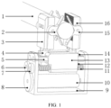
FIG. 1 is a structural schematic diagram of the present invention. -
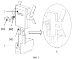
FIG. 2 is a schematic diagram showing an internal structure of a panel during disassembly and assembly of the present invention. - The reference numerals:
- intervening equipment 1
-
left gathering piece 2 - left clamping
panel 3 - unlocking
tool 301 -
reset spring 302 -
resilient locking piece 303 - back moving
assembly 4 - front guiding
rail 5 - back
cogwheel 6 -
front cogwheel 7 -
electric motor cogwheel 8 -
frame 9 -
electric motor 10 -
front screw rod 11 -
back screw rod 12 - front moving
assembly 13 - back guiding
rail 14 -
right gathering piece 15 -
right clamping panel 16 - As follows, the present invention is described in detail in conjunction with specific embodiments. The following embodiments help the skilled in the art to further understand the present invention, but do not limit it in any way. It should be noted that to a person of ordinary skill in the art, a number of variations and improvements can be made without departing from the ideas of the present invention. The scope of the invention is defined by the appended claims.
- As shown in
FIG. 1 andFIG. 2 , the present invention provides elastic gathered automatically centering panel clamping mechanical fingers for vascular intervention. The mechanical fingers include theleft gathering pieces 2, theleft clamping panel 3, theright gathering pieces 15, theright clamping panel 16, theframe 9, and a linear-propelling mechanism. The linear-propelling mechanism includes thefront screw rod 11, the front movingassembly 13, thefront guiding rail 5, thefront cogwheel 7, theback screw rod 12, the back movingassembly 4, theback guiding rail 14, theback cogwheel 6, theelectric motor cogwheel 8, and theelectric motor 10. As shown inFIG. 1 , the front direction in the present invention refers to the direction perpendicular to the paper and pointing outwards, and the back direction in the present invention refers to the direction perpendicular to the paper and pointing inwards. The linear-propelling mechanism is arranged on theframe 9. Theframe 9 includes a bottom board and parallel sideboards separately arranged on two sides of the bottom board, and the front guidingrail 5, thefront screw rod 11, theback guiding rail 14, and theback screw rod 12 are all arranged on the sideboards on the two sides of the bottom board. One pair of theleft gathering pieces 2 are arranged on the front side and back side of theleft clamping panel 3, respectively. Theleft clamping panel 3 is arranged on theback moving assembly 4. Theback moving assembly 4 and theback screw rod 12 are screwed and fitted with each other, and scotched by theback guiding rail 14. Theback cogwheel 6 is fixedly arranged on one end of theback screw rod 12. Theright gathering pieces 15 are separately arranged on sides of theright clamping panel 16. Theright clamping panel 16 is arranged on the front movingassembly 13. The front movingassembly 13 and thefront screw rod 11 are screwed and fitted with each other, and scotched by thefront guiding rail 5. Thefront cogwheel 7 is arranged on one end of thefront screw rod 11. The design method that separates the arrangements of theback moving assembly 4 and the front movingassembly 13 ensures that each of theback moving assembly 4 and the front movingassembly 13 has a comparatively longer length, avoiding motional stagnation caused by pulling and pressing the intervening equipment 1. - Further, the
left clamping panel 3 and theright clamping panel 16 moves towards each other to clamp the intervening equipment 1, and theleft gathering pieces 2 and theright gathering pieces 15 have V-shaped structures for gathering and automatically centering the intervening equipment 1. Under the condition that the diameter of the intervening equipment 1 is quite small, theleft gathering pieces 2 and theright gathering pieces 15 press each other, which can be deformed to be at an equal level with contacting surfaces of theleft clamping panel 3 and theright clamping panel 16. The contacting surfaces of theleft clamping panel 3 and theright clamping panel 16 are arranged to be resilient contacting surfaces, and the contacting surfaces flexibly contact the intervening equipment 1 to avoid damage. Additionally, the contacting surfaces are embossed with grids to increase friction and to avoid slipping. - Further, the front moving
assembly 13 has the same structure as theback moving assembly 4. Theback moving assembly 4 is taken as an example for demonstration. Theback moving assembly 4 is provided with a position-limiting block. The bottom of theleft clamping panel 3 is arranged with an installing slot. Theleft clamping panel 3 inserts into the installing slot by the position-limiting block, to be arranged on theback moving assembly 4. The upper end of the position-limiting block is provided with theresilient locking pieces 303. The interior wall of the installing slot is provided with position-limiting through-holes. When the position-limiting block is inserted into the installing slot, theresilient locking pieces 303 clamp into the position-limiting through-holes to realize the fixed connection between the moving assemblies and the left clamping panel or the right clamping panel. Theleft clamping panel 3 is provided with the unlockingtool 301. The unlockingtool 301 can extend into the position-limiting through-holes and push theresilient locking pieces 303 away from the position-limiting through-holes. Thereset spring 302 is configured to connect and fix the unlockingtool 301 to theleft clamping panel 3. Theleft clamping panel 3 and theright clamping panel 16 are sterilized for reuse, or discarded as disposable consumables. - Further, the
front cogwheel 7 and theback cogwheel 6 are engaged with theelectric motor cogwheel 8 that is arranged on the output shaft of theelectric motor 10 at the same time. Thefront screw rod 11 and theback screw rod 12 are parallelly arranged on theframe 9 with the threads of the two screw rods going inverse directions relative to each other. When thefront cogwheel 7 and theback cogwheel 6 driving the screw rods is engaged with theelectric motor cogwheel 8 of theelectric motor 10 to rotate, thefront screw rod 11 and theback screw rod 12 rotate in the same direction simultaneously, and theback moving assembly 4 and the front movingassembly 13 moves towards or away with each other simultaneously to realize centering clamping or loosening the intervening equipment 1. - As a varied embodiment, after the
front cogwheel 7 and theback cogwheel 6 are engaged with each other, one of them engages with theelectric motor cogwheel 8 on the output shaft of theelectric motor 10, and threads of thefront screw rod 11 and theback screw rod 12 go in the same direction. - By selecting the preferred embodiment as an example, the workflow of the present invention is demonstrated as follows. When the
electric motor 10 rotates, theelectric motor cogwheel 8 drives thefront cogwheel 7 and theback cogwheel 6 to rotate in the same direction. Since the threads of thefront screw rod 11 and theback screw rod 12 go inverse directions, the front movingassembly 13 and theback moving assembly 4 move simultaneously in inverse directions on thefront guiding rail 5 and theback guiding rail 14. Thefront screw rod 11 and theback screw rod 12 are equal in screw pitch, and moving distance and velocity. When theleft clamping panel 3 and theright clamping panel 16 are moving towards each other, theleft gathering pieces 2 and theright gathering pieces 15 automatically center the intervening equipment 1. When they have moved to a certain distance, the objective of stably clamping is realized. - Specific embodiments of the present invention are described above. It should be understood that the present invention is not limited to the particular embodiments described above, and that the skilled in the art may make various variations or modifications within the scope of the claims, which do not affect the substance of the present invention.
Claims (7)
- Elastic gathered automatically centering panel clamping mechanical fingers for a vascular intervention, comprising a left clamping panel (3), a right clamping panel (16), left gathering pieces (2), right gathering pieces (15), a linear-propelling mechanism, and a frame (9), whereinthe linear-propelling mechanism is arranged on the frame (9);the left clamping panel (3) and the right clamping panel (16) are oppositely arranged, and the left clamping panel (3) and the right clamping panel (16) are each arranged on the linear-propelling mechanism;the left gathering pieces (2) are arranged on the left clamping panel (3), and the right gathering pieces (15) are arranged on the right clamping panel (16); andthe linear-propelling mechanism drives the left clamping panel (3) and the right clamping panel (16) to move towards each other, or the linear-propelling mechanism drives the left clamping panel (3) and the right clamping panel (16) to move away from each other; wherein the left gathering pieces (2) and right gathering pieces (15) have V-shaped structure that achieves the centering; contacting surfaces ofthe left gathering pieces (2) and
contacting surfaces of the right gathering pieces (15) are contacting surfaces resiliently arranged, and the contacting surfaces are configured to come in contact with an intervening equipment when the intervening equipment is clamped by the gathering pieces (2, 15);the linear-propelling mechanism comprises a driving electric motor (10) and two moving assemblies (4, 13), wherein the left clamping panel (3) is arranged on a first moving assembly, and the right clamping panel (16) is arranged on a second moving assembly; each of the moving assemblies is provided with position-limiting holes and threaded holes; an axial direction of each of the position-limiting holes and an axial direction of each of the threaded holes is the same; and characterized in thatthe linear-propelling mechanism further comprises two position-limiting guiding rails (5, 14) and two adjusting screw rods (11, 12), whereineach of the position-limiting guiding rails is arranged in the position-limiting hole of corresponding moving assembly, and each of the adjusting screw rods is arranged in the threaded hole of corresponding moving assembly;each of the adjusting screw rods drives each of the moving assemblies to move reciprocally on each of the position-limiting guiding rails by a rotating motion;an output end of the driving electric motor (10) and one end of each of the adjusting screw rods are engaged by a cogwheel (8);and the driving electric motor (10) drives each of the adjusting screw rods to rotate by the cogwheel. - The mechanical fingers according to claim 1, wherein the left gathering pieces (2) are arranged on two sides of the left clamping panel (3), respectively; the right gathering pieces (15) are arranged on two sides of the right clamping panel (16), respectively; and the contacting surfaces of each of the left gathering pieces (2) and the contacting surfaces of each of the right gathering pieces (15) are arranged to face each other.
- The mechanical fingers according to claim 1, wherein a first moving assembly of the moving assemblies is provided with a first position-limiting block, and a second moving assembly of the moving assemblies is provided with a second position-limiting block; a bottom of the left clamping panel (3) is provided with a first installing slot, and a bottom of the right clamping panel (16) is provided with a second installing slot; and the left clamping panel (3) inserts into the first installing slot by the first position-limiting block to be arranged on the first moving assembly, and the right clamping panel (16) inserts into the second installing slot by the second position-limiting block to be arranged on the second moving assembly.
- The mechanical fingers according to claim 3, wherein an upper end of the first position-limiting block is provided with a first resilient locking piece (303), and an upper end of the second position-limiting block is provided with a second resilient locking piece (303); an interior wall of the first installing slot is provided with a first position-limiting through-hole, and an interior wall of the second installing slot is provided with a second position-limiting through-hole; and when the first position-limiting block is inserted into the first installing slot, and the second position-limiting block is inserted into the second installing slot, the first resilient locking piece (303) clamps into the first position-limiting through-hole, and the second resilient locking piece (303) clamps into the second position-limiting through-hole to realize a fixed connection between the first moving assembly and the left clamping panel (3) and a fixed connection between the second moving assembly and the right clamping panel (16).
- The mechanical fingers according to claim 4, wherein the mechanical fingers further comprise an unlocking tool (301); and the unlocking tool (301) is configured to extend into the first position-limiting through-hole and the second position-limiting through-hole to push the first resilient locking piece (303) and the second resilient locking piece (303) away from the first position-limiting through-hole and the second position-limiting through-hole, respectively.
- The mechanical fingers according to claim 1, wherein the frame (9) comprises a bottom board and parallel sideboards, wherein the parallel sideboards are arranged on two sides of the bottom board, respectively; and each of the position-limiting guiding rails and each of the adjusting screw rods are arranged on the parallel sideboards.
- The mechanical fingers according to claim 1, wherein the contacting surfaces of each of the left gathering pieces (2) and the contacting surfaces of each of the right gathering pieces (15) are ribbed surfaces that increase friction.
Applications Claiming Priority (2)
| Application Number | Priority Date | Filing Date | Title |
|---|---|---|---|
| CN202010188608.7A CN111329582B (en) | 2020-03-17 | 2020-03-17 | Elastic gathering self-centering flat clamping mechanical finger for blood vessel intervention |
| PCT/CN2020/083458 WO2021184443A1 (en) | 2020-03-17 | 2020-04-07 | Elastic gathered self-centering panel clamping mechanical finger for blood vessel intervention |
Publications (4)
| Publication Number | Publication Date |
|---|---|
| EP4108199A1 EP4108199A1 (en) | 2022-12-28 |
| EP4108199A4 EP4108199A4 (en) | 2023-07-26 |
| EP4108199B1 true EP4108199B1 (en) | 2024-07-10 |
| EP4108199C0 EP4108199C0 (en) | 2024-07-10 |
Family
ID=71174649
Family Applications (1)
| Application Number | Title | Priority Date | Filing Date |
|---|---|---|---|
| EP20925043.0A Active EP4108199B1 (en) | 2020-03-17 | 2020-04-07 | Elastic gathered self-centering panel clamping mechanical finger for blood vessel intervention |
Country Status (5)
| Country | Link |
|---|---|
| US (1) | US12419710B2 (en) |
| EP (1) | EP4108199B1 (en) |
| JP (1) | JP7402351B2 (en) |
| CN (1) | CN111329582B (en) |
| WO (1) | WO2021184443A1 (en) |
Families Citing this family (9)
| Publication number | Priority date | Publication date | Assignee | Title |
|---|---|---|---|---|
| CN113367843B (en) * | 2021-04-27 | 2023-08-15 | 杭州启明医疗器械股份有限公司 | Delivery systems for interventional devices |
| CN116059502A (en) * | 2021-11-04 | 2023-05-05 | 杭州德诺脑神经医疗科技有限公司 | Guide wire control system |
| CN116059501A (en) * | 2021-11-04 | 2023-05-05 | 杭州德诺脑神经医疗科技有限公司 | Guide wire clamping and conveying device, guide wire control system and position adjustment method |
| CN114796797B (en) * | 2022-04-01 | 2023-12-29 | 北京唯迈医疗设备有限公司 | A control device for a guiding catheter and an imaging catheter |
| CN114603220B (en) * | 2022-05-16 | 2022-07-22 | 江苏中动机械科技有限公司 | Screw pitch control mechanism for reinforcing steel bar thread processing machine |
| CN115153849A (en) * | 2022-06-30 | 2022-10-11 | 上海奥朋医疗科技有限公司 | Force feedback sensing device based on disposable instrument of laparoscopic surgery robot and laparoscopic surgery robot |
| CN115738032A (en) * | 2022-10-21 | 2023-03-07 | 中国科学院长春光学精密机械与物理研究所 | Catheter clamping mechanism for vascular intervention |
| WO2025195791A1 (en) * | 2024-03-21 | 2025-09-25 | Lem Surgical Ag | Systems and methods for robotically manipulating elongate surgical tools |
| CN119780127A (en) * | 2025-01-07 | 2025-04-08 | 江苏海洋大学 | An online detection device for bubble gas line of secondary heat-processed quartz expansion tube |
Family Cites Families (28)
| Publication number | Priority date | Publication date | Assignee | Title |
|---|---|---|---|---|
| JPS59151687U (en) | 1983-03-30 | 1984-10-11 | 株式会社東芝 | gripping device |
| JPS61201790U (en) | 1985-06-08 | 1986-12-18 | ||
| JPS6427874A (en) * | 1987-07-23 | 1989-01-30 | Toshiba Corp | Robot hand |
| EP1907041B1 (en) * | 2005-07-11 | 2019-02-20 | Catheter Precision, Inc. | Remotely controlled catheter insertion system |
| CN100368158C (en) * | 2006-04-21 | 2008-02-13 | 北京航空航天大学 | Two-Finger Dexterous Gripper |
| CN101612436B (en) * | 2009-07-23 | 2011-09-28 | 北京航空航天大学 | Robot propulsion mechanism for blood vessel intervention operation |
| CN102210610B (en) * | 2011-03-17 | 2013-06-05 | 北京航空航天大学 | Pushing mechanism for minimally invasive surgical robot |
| CN102785251B (en) | 2012-07-06 | 2015-11-11 | 深圳先进技术研究院 | Make up a prescription the mechanical paw of robot |
| GB201219491D0 (en) * | 2012-10-30 | 2012-12-12 | Rainbow Medical Ltd | Surgical controller |
| CN103083783B (en) * | 2013-02-25 | 2014-07-23 | 中国科学院自动化研究所 | Clamping-based catheter or clamping-based guide wire operating device for vessel interventional operation |
| US20140277334A1 (en) * | 2013-03-14 | 2014-09-18 | Hansen Medical, Inc. | Active drives for robotic catheter manipulators |
| US9326822B2 (en) * | 2013-03-14 | 2016-05-03 | Hansen Medical, Inc. | Active drives for robotic catheter manipulators |
| CN103433929B (en) | 2013-06-03 | 2015-10-21 | 浙江大学 | A kind of two refer to translation manipulator |
| CN103599585B (en) * | 2013-11-20 | 2016-06-15 | 中国科学院深圳先进技术研究院 | Blood vessel intervention operation wire catheter operating gear and operation module thereof |
| CN104287841B (en) * | 2014-11-10 | 2016-05-04 | 上海速介机器人科技有限公司 | Blood vessel intervention operation robot wire catheter manipulation device and control method thereof |
| CN104644270B (en) * | 2015-02-05 | 2016-09-07 | 北京航空航天大学 | A kind of catheter steering device based on reverse leading screw |
| JP6428532B2 (en) * | 2015-08-24 | 2018-11-28 | 株式会社安川電機 | Robot hand and robot hand cover |
| US9505135B1 (en) | 2015-08-28 | 2016-11-29 | Tyco Electronics Corporation | Gripper with conformal spring fingers |
| US9931170B2 (en) * | 2016-01-06 | 2018-04-03 | Ethicon Endo-Surgery, Llc | Methods, systems, and devices for moving a surgical instrument coupled to a robotic surgical system |
| CN206950441U (en) * | 2016-12-15 | 2018-02-02 | 杭州启明医疗器械有限公司 | The seal wire adjuster and induction system joystick of a kind of wheel drive |
| CN106880380A (en) * | 2017-03-21 | 2017-06-23 | 上海大学 | Blood vessel intervention operation wire catheter operation device |
| WO2018176458A1 (en) * | 2017-04-01 | 2018-10-04 | 中国科学院深圳先进技术研究院 | Catheter advancing controlling method and catheter advancing device for vessel interventional surgery robot |
| CN107049499B (en) | 2017-06-05 | 2019-10-29 | 上海速介机器人科技有限公司 | Teleoperation vascular intervention surgical robot system and method |
| CN107320181A (en) * | 2017-06-05 | 2017-11-07 | 上海速介机器人科技有限公司 | The folder that wire catheter is operated in blood vessel intervention operation transfers manipulator |
| CN109199590B (en) * | 2018-10-11 | 2020-07-14 | 上海奥朋医疗科技有限公司 | Channel-changing and cis-positioning operation manipulator for vascular intervention and surgical robot |
| CN110327116B (en) * | 2019-07-09 | 2020-06-30 | 中国科学院自动化研究所 | Catheter delivery device of vascular intervention surgical robot |
| EP4221605B1 (en) * | 2020-10-02 | 2026-01-28 | Intuitive Surgical Operations, Inc. | Medical devices having compact end effector drive mechanisms with high grip force |
| IT202100016175A1 (en) * | 2021-06-21 | 2022-12-21 | Medical Microinstruments Inc | Surgical cutting tool, rotational joint and method, particularly for robotic surgery and/or micro-surgery |
-
2020
- 2020-03-17 CN CN202010188608.7A patent/CN111329582B/en active Active
- 2020-04-07 US US17/912,488 patent/US12419710B2/en active Active
- 2020-04-07 EP EP20925043.0A patent/EP4108199B1/en active Active
- 2020-04-07 JP JP2022556085A patent/JP7402351B2/en active Active
- 2020-04-07 WO PCT/CN2020/083458 patent/WO2021184443A1/en not_active Ceased
Also Published As
| Publication number | Publication date |
|---|---|
| CN111329582B (en) | 2021-04-13 |
| US12419710B2 (en) | 2025-09-23 |
| WO2021184443A1 (en) | 2021-09-23 |
| EP4108199C0 (en) | 2024-07-10 |
| CN111329582A (en) | 2020-06-26 |
| JP7402351B2 (en) | 2023-12-20 |
| EP4108199A4 (en) | 2023-07-26 |
| US20230142137A1 (en) | 2023-05-11 |
| BR112022018301A2 (en) | 2022-10-25 |
| JP2023518428A (en) | 2023-05-01 |
| EP4108199A1 (en) | 2022-12-28 |
Similar Documents
| Publication | Publication Date | Title |
|---|---|---|
| EP4108199A1 (en) | Elastic gathered self-centering panel clamping mechanical finger for blood vessel intervention | |
| CN113633383B (en) | Guide wire/catheter delivery device for vascular intervention, use method thereof and vascular intervention surgical robot | |
| CN102210610B (en) | Pushing mechanism for minimally invasive surgical robot | |
| CN112353491B (en) | Universal robot for interventional radiography and therapeutic surgery | |
| CN110200700B (en) | A vascular interventional surgery robot and equipment | |
| CN113598955B (en) | A minimally invasive surgical robot power transmission mechanism | |
| CN113633382A (en) | Guide wire/catheter delivery device for vascular interventional surgery robot and vascular interventional surgery robot | |
| CN109106449A (en) | A kind of cardiovascular and cerebrovascular intervention operation robot and its wire catheter method for pushing | |
| CN114191092A (en) | Interventional operation robot slave end delivery device | |
| CN114191101A (en) | Multifunctional slave end driving device of interventional operation robot | |
| JP7833807B2 (en) | Treatment tool control device | |
| CN109199590B (en) | Channel-changing and cis-positioning operation manipulator for vascular intervention and surgical robot | |
| CN118742272A (en) | End effector unit, surgical device, arm device and manipulator system | |
| CN116269810B (en) | Master manipulator of master-slave type ophthalmic surgery robot with force feedback function | |
| CN111202586A (en) | Continuous clamping and rotating method and system of single manipulator for vascular intervention | |
| CN120813314A (en) | Controlling a robotic system actuator for driving an elongated flexible medical device | |
| CN113425413A (en) | Mechanical claw for interventional vascular surgery | |
| CN114366312B (en) | Liver tumor embolization interventional surgery robot | |
| CN118304001A (en) | Interventional driving device and surgical robot | |
| CN110774309A (en) | Single-drive three-finger mechanical gripper | |
| CN116138880B (en) | Interventional surgery robot and clamping device thereof | |
| CN1283429C (en) | Humanoid manipulator mechanism | |
| CN115590624B (en) | Guide wire catheter conveying device for endovascular interventional operation robot | |
| CN116019559B (en) | Guide wire catheter control and force feedback device of endovascular interventional surgical robot | |
| BR112022018301B1 (en) | Mechanical Fingers for Automatic Centering Panel Gripping with Elastic Retraction for Vascular Intervention |
Legal Events
| Date | Code | Title | Description |
|---|---|---|---|
| STAA | Information on the status of an ep patent application or granted ep patent |
Free format text: STATUS: THE INTERNATIONAL PUBLICATION HAS BEEN MADE |
|
| PUAI | Public reference made under article 153(3) epc to a published international application that has entered the european phase |
Free format text: ORIGINAL CODE: 0009012 |
|
| STAA | Information on the status of an ep patent application or granted ep patent |
Free format text: STATUS: REQUEST FOR EXAMINATION WAS MADE |
|
| 17P | Request for examination filed |
Effective date: 20220922 |
|
| AK | Designated contracting states |
Kind code of ref document: A1 Designated state(s): AL AT BE BG CH CY CZ DE DK EE ES FI FR GB GR HR HU IE IS IT LI LT LU LV MC MK MT NL NO PL PT RO RS SE SI SK SM TR |
|
| REG | Reference to a national code |
Ref country code: DE Ipc: A61M0025010000 Ref legal event code: R079 Ref document number: 602020033932 Country of ref document: DE Free format text: PREVIOUS MAIN CLASS: A61B0034000000 |
|
| DAV | Request for validation of the european patent (deleted) | ||
| DAX | Request for extension of the european patent (deleted) | ||
| A4 | Supplementary search report drawn up and despatched |
Effective date: 20230623 |
|
| RIC1 | Information provided on ipc code assigned before grant |
Ipc: A61B 34/30 20160101ALI20230619BHEP Ipc: A61M 25/02 20060101ALI20230619BHEP Ipc: A61M 25/01 20060101AFI20230619BHEP |
|
| GRAP | Despatch of communication of intention to grant a patent |
Free format text: ORIGINAL CODE: EPIDOSNIGR1 |
|
| STAA | Information on the status of an ep patent application or granted ep patent |
Free format text: STATUS: GRANT OF PATENT IS INTENDED |
|
| INTG | Intention to grant announced |
Effective date: 20240205 |
|
| GRAS | Grant fee paid |
Free format text: ORIGINAL CODE: EPIDOSNIGR3 |
|
| GRAA | (expected) grant |
Free format text: ORIGINAL CODE: 0009210 |
|
| STAA | Information on the status of an ep patent application or granted ep patent |
Free format text: STATUS: THE PATENT HAS BEEN GRANTED |
|
| AK | Designated contracting states |
Kind code of ref document: B1 Designated state(s): AL AT BE BG CH CY CZ DE DK EE ES FI FR GB GR HR HU IE IS IT LI LT LU LV MC MK MT NL NO PL PT RO RS SE SI SK SM TR |
|
| REG | Reference to a national code |
Ref country code: CH Ref legal event code: EP |
|
| REG | Reference to a national code |
Ref country code: DE Ref legal event code: R096 Ref document number: 602020033932 Country of ref document: DE |
|
| U01 | Request for unitary effect filed |
Effective date: 20240808 |
|
| U07 | Unitary effect registered |
Designated state(s): AT BE BG DE DK EE FI FR IT LT LU LV MT NL PT SE SI Effective date: 20240821 |
|
| PG25 | Lapsed in a contracting state [announced via postgrant information from national office to epo] |
Ref country code: NO Free format text: LAPSE BECAUSE OF FAILURE TO SUBMIT A TRANSLATION OF THE DESCRIPTION OR TO PAY THE FEE WITHIN THE PRESCRIBED TIME-LIMIT Effective date: 20241010 |
|
| PG25 | Lapsed in a contracting state [announced via postgrant information from national office to epo] |
Ref country code: GR Free format text: LAPSE BECAUSE OF FAILURE TO SUBMIT A TRANSLATION OF THE DESCRIPTION OR TO PAY THE FEE WITHIN THE PRESCRIBED TIME-LIMIT Effective date: 20241011 Ref country code: PL Free format text: LAPSE BECAUSE OF FAILURE TO SUBMIT A TRANSLATION OF THE DESCRIPTION OR TO PAY THE FEE WITHIN THE PRESCRIBED TIME-LIMIT Effective date: 20240710 |
|
| PG25 | Lapsed in a contracting state [announced via postgrant information from national office to epo] |
Ref country code: IS Free format text: LAPSE BECAUSE OF FAILURE TO SUBMIT A TRANSLATION OF THE DESCRIPTION OR TO PAY THE FEE WITHIN THE PRESCRIBED TIME-LIMIT Effective date: 20241110 |
|
| PG25 | Lapsed in a contracting state [announced via postgrant information from national office to epo] |
Ref country code: HR Free format text: LAPSE BECAUSE OF FAILURE TO SUBMIT A TRANSLATION OF THE DESCRIPTION OR TO PAY THE FEE WITHIN THE PRESCRIBED TIME-LIMIT Effective date: 20240710 |
|
| PG25 | Lapsed in a contracting state [announced via postgrant information from national office to epo] |
Ref country code: ES Free format text: LAPSE BECAUSE OF FAILURE TO SUBMIT A TRANSLATION OF THE DESCRIPTION OR TO PAY THE FEE WITHIN THE PRESCRIBED TIME-LIMIT Effective date: 20240710 Ref country code: RS Free format text: LAPSE BECAUSE OF FAILURE TO SUBMIT A TRANSLATION OF THE DESCRIPTION OR TO PAY THE FEE WITHIN THE PRESCRIBED TIME-LIMIT Effective date: 20241010 |
|
| PG25 | Lapsed in a contracting state [announced via postgrant information from national office to epo] |
Ref country code: RS Free format text: LAPSE BECAUSE OF FAILURE TO SUBMIT A TRANSLATION OF THE DESCRIPTION OR TO PAY THE FEE WITHIN THE PRESCRIBED TIME-LIMIT Effective date: 20241010 Ref country code: PL Free format text: LAPSE BECAUSE OF FAILURE TO SUBMIT A TRANSLATION OF THE DESCRIPTION OR TO PAY THE FEE WITHIN THE PRESCRIBED TIME-LIMIT Effective date: 20240710 Ref country code: NO Free format text: LAPSE BECAUSE OF FAILURE TO SUBMIT A TRANSLATION OF THE DESCRIPTION OR TO PAY THE FEE WITHIN THE PRESCRIBED TIME-LIMIT Effective date: 20241010 Ref country code: IS Free format text: LAPSE BECAUSE OF FAILURE TO SUBMIT A TRANSLATION OF THE DESCRIPTION OR TO PAY THE FEE WITHIN THE PRESCRIBED TIME-LIMIT Effective date: 20241110 Ref country code: HR Free format text: LAPSE BECAUSE OF FAILURE TO SUBMIT A TRANSLATION OF THE DESCRIPTION OR TO PAY THE FEE WITHIN THE PRESCRIBED TIME-LIMIT Effective date: 20240710 Ref country code: GR Free format text: LAPSE BECAUSE OF FAILURE TO SUBMIT A TRANSLATION OF THE DESCRIPTION OR TO PAY THE FEE WITHIN THE PRESCRIBED TIME-LIMIT Effective date: 20241011 Ref country code: ES Free format text: LAPSE BECAUSE OF FAILURE TO SUBMIT A TRANSLATION OF THE DESCRIPTION OR TO PAY THE FEE WITHIN THE PRESCRIBED TIME-LIMIT Effective date: 20240710 |
|
| PG25 | Lapsed in a contracting state [announced via postgrant information from national office to epo] |
Ref country code: SM Free format text: LAPSE BECAUSE OF FAILURE TO SUBMIT A TRANSLATION OF THE DESCRIPTION OR TO PAY THE FEE WITHIN THE PRESCRIBED TIME-LIMIT Effective date: 20240710 |
|
| PG25 | Lapsed in a contracting state [announced via postgrant information from national office to epo] |
Ref country code: CZ Free format text: LAPSE BECAUSE OF FAILURE TO SUBMIT A TRANSLATION OF THE DESCRIPTION OR TO PAY THE FEE WITHIN THE PRESCRIBED TIME-LIMIT Effective date: 20240710 |
|
| PG25 | Lapsed in a contracting state [announced via postgrant information from national office to epo] |
Ref country code: SK Free format text: LAPSE BECAUSE OF FAILURE TO SUBMIT A TRANSLATION OF THE DESCRIPTION OR TO PAY THE FEE WITHIN THE PRESCRIBED TIME-LIMIT Effective date: 20240710 |
|
| PLBE | No opposition filed within time limit |
Free format text: ORIGINAL CODE: 0009261 |
|
| STAA | Information on the status of an ep patent application or granted ep patent |
Free format text: STATUS: NO OPPOSITION FILED WITHIN TIME LIMIT |
|
| U20 | Renewal fee for the european patent with unitary effect paid |
Year of fee payment: 6 Effective date: 20250428 |
|
| 26N | No opposition filed |
Effective date: 20250411 |
|
| PGFP | Annual fee paid to national office [announced via postgrant information from national office to epo] |
Ref country code: GB Payment date: 20250428 Year of fee payment: 6 |
|
| PGFP | Annual fee paid to national office [announced via postgrant information from national office to epo] |
Ref country code: IE Payment date: 20250428 Year of fee payment: 6 |
|
| REG | Reference to a national code |
Ref country code: CH Ref legal event code: H13 Free format text: ST27 STATUS EVENT CODE: U-0-0-H10-H13 (AS PROVIDED BY THE NATIONAL OFFICE) Effective date: 20251125 |
|
| PG25 | Lapsed in a contracting state [announced via postgrant information from national office to epo] |
Ref country code: MC Free format text: LAPSE BECAUSE OF FAILURE TO SUBMIT A TRANSLATION OF THE DESCRIPTION OR TO PAY THE FEE WITHIN THE PRESCRIBED TIME-LIMIT Effective date: 20240710 |
|
| PG25 | Lapsed in a contracting state [announced via postgrant information from national office to epo] |
Ref country code: CH Free format text: LAPSE BECAUSE OF NON-PAYMENT OF DUE FEES Effective date: 20250430 |
|
| PG25 | Lapsed in a contracting state [announced via postgrant information from national office to epo] |
Ref country code: RO Free format text: LAPSE BECAUSE OF FAILURE TO SUBMIT A TRANSLATION OF THE DESCRIPTION OR TO PAY THE FEE WITHIN THE PRESCRIBED TIME-LIMIT Effective date: 20240710 |