EP4108156A1 - Endoscope eyepiece grasping mechanism and endoscope camera head with endoscope eyepiece grasping mechanism - Google Patents
Endoscope eyepiece grasping mechanism and endoscope camera head with endoscope eyepiece grasping mechanism Download PDFInfo
- Publication number
- EP4108156A1 EP4108156A1 EP22179867.1A EP22179867A EP4108156A1 EP 4108156 A1 EP4108156 A1 EP 4108156A1 EP 22179867 A EP22179867 A EP 22179867A EP 4108156 A1 EP4108156 A1 EP 4108156A1
- Authority
- EP
- European Patent Office
- Prior art keywords
- endoscope
- eyepiece
- grasping mechanism
- endoscope eyepiece
- base part
- Prior art date
- Legal status (The legal status is an assumption and is not a legal conclusion. Google has not performed a legal analysis and makes no representation as to the accuracy of the status listed.)
- Granted
Links
Images


Classifications
-
- A—HUMAN NECESSITIES
- A61—MEDICAL OR VETERINARY SCIENCE; HYGIENE
- A61B—DIAGNOSIS; SURGERY; IDENTIFICATION
- A61B1/00—Instruments for performing medical examinations of the interior of cavities or tubes of the body by visual or photographical inspection, e.g. endoscopes; Illuminating arrangements therefor
- A61B1/00112—Connection or coupling means
- A61B1/00121—Connectors, fasteners and adapters, e.g. on the endoscope handle
- A61B1/00126—Connectors, fasteners and adapters, e.g. on the endoscope handle optical, e.g. for light supply cables
-
- A—HUMAN NECESSITIES
- A61—MEDICAL OR VETERINARY SCIENCE; HYGIENE
- A61B—DIAGNOSIS; SURGERY; IDENTIFICATION
- A61B1/00—Instruments for performing medical examinations of the interior of cavities or tubes of the body by visual or photographical inspection, e.g. endoscopes; Illuminating arrangements therefor
- A61B1/00112—Connection or coupling means
-
- A—HUMAN NECESSITIES
- A61—MEDICAL OR VETERINARY SCIENCE; HYGIENE
- A61B—DIAGNOSIS; SURGERY; IDENTIFICATION
- A61B1/00—Instruments for performing medical examinations of the interior of cavities or tubes of the body by visual or photographical inspection, e.g. endoscopes; Illuminating arrangements therefor
- A61B1/00112—Connection or coupling means
- A61B1/00121—Connectors, fasteners and adapters, e.g. on the endoscope handle
- A61B1/00128—Connectors, fasteners and adapters, e.g. on the endoscope handle mechanical, e.g. for tubes or pipes
-
- A—HUMAN NECESSITIES
- A61—MEDICAL OR VETERINARY SCIENCE; HYGIENE
- A61B—DIAGNOSIS; SURGERY; IDENTIFICATION
- A61B1/00—Instruments for performing medical examinations of the interior of cavities or tubes of the body by visual or photographical inspection, e.g. endoscopes; Illuminating arrangements therefor
- A61B1/00163—Optical arrangements
- A61B1/00195—Optical arrangements with eyepieces
-
- A—HUMAN NECESSITIES
- A61—MEDICAL OR VETERINARY SCIENCE; HYGIENE
- A61B—DIAGNOSIS; SURGERY; IDENTIFICATION
- A61B1/00—Instruments for performing medical examinations of the interior of cavities or tubes of the body by visual or photographical inspection, e.g. endoscopes; Illuminating arrangements therefor
- A61B1/04—Instruments for performing medical examinations of the interior of cavities or tubes of the body by visual or photographical inspection, e.g. endoscopes; Illuminating arrangements therefor combined with photographic or television appliances
- A61B1/042—Instruments for performing medical examinations of the interior of cavities or tubes of the body by visual or photographical inspection, e.g. endoscopes; Illuminating arrangements therefor combined with photographic or television appliances characterised by a proximal camera, e.g. a CCD camera
Definitions
- the present invention relates generally to endoscopic camera devices and more particularly to a grasping mechanism or coupler to be fixed on a camera head device or similar optical device to couple the device with an optical endoscope.
- an endoscope eyepiece grasping mechanism for an endoscope camera head.
- the endoscope eyepiece grasping mechanism comprises a base part with a central eyepiece receiving region with a light passage opening, the base part comprising an axially extending wall.
- a radially moveable tab member is positioned relative to the axially extending wall with an engagement member connected to the tab member.
- An annular part is provided comprising an outer engagement surface and an inner camming surface. The annular part is disposed coaxially with the base part and is axially moveable in an axial direction relative to the base part.
Landscapes
- Health & Medical Sciences (AREA)
- Life Sciences & Earth Sciences (AREA)
- Surgery (AREA)
- Engineering & Computer Science (AREA)
- Biomedical Technology (AREA)
- Heart & Thoracic Surgery (AREA)
- Pathology (AREA)
- Radiology & Medical Imaging (AREA)
- Nuclear Medicine, Radiotherapy & Molecular Imaging (AREA)
- Biophysics (AREA)
- Physics & Mathematics (AREA)
- Optics & Photonics (AREA)
- Medical Informatics (AREA)
- Molecular Biology (AREA)
- Animal Behavior & Ethology (AREA)
- General Health & Medical Sciences (AREA)
- Public Health (AREA)
- Veterinary Medicine (AREA)
- Mechanical Engineering (AREA)
- Endoscopes (AREA)
Abstract
Description
- The present invention relates generally to endoscopic camera devices and more particularly to a grasping mechanism or coupler to be fixed on a camera head device or similar optical device to couple the device with an optical endoscope.
- Endoscopic devices are used in the medical field for observing inside of a patient's body cavity. Such endoscopic devices include an insertion unit to be inserted into a patient's body cavity, a light source device that supplies light to the insertion unit that shines onto a target of observation and a removable camera head which is coupled to an eyepiece at the base of the endoscope. The camera head may be associated with a control device that controls the camera head as well as a display device that displays images produced by the camera head imaging device such as a CCD, CMOS or similar imaging device.
- Camera heads are often provided with a grasping mechanism to grasp the eyepiece of an endoscope to effectively couple the endoscope to the camera head. Current grasping mechanism include a rotatable coupling feature. For clinicians/surgeons that rotate the scope within the grasping mechanism, this can cause the scope to inadvertently become decoupled from the camera head. Also, for camera heads with rotatable focus or zoom control, a rotatable grasping mechanism presents another rotatable feature adding to confusion or unwanted adjustment or decoupling. Additionally, some cameras (pendulum models) are designed specifically with the grasping mechanism allowed to freely rotate about the optical axis. Using a rotatable coupling feature then requires an additional rotational lock feature in order to insert or remove endoscopes. Further, twist on and off grasping mechanisms use more parts including many machined parts which entails higher costs.
- It is an object of the invention to provide an endoscope eyepiece grasping mechanism (coupling feature) that comprises a push-pull mechanism so as to eliminate the problems of unwanted adjustment or decoupling associated with rotational mechanisms that provide grasping/coupling.
- It is another object of the invention to provide a grasping mechanism (coupling feature) that avoids a need to rotationally lock the grasping mechanism, particularly on pendulum cameras, in order to insert or remove endoscopes from such a camera.
- According to the invention, an endoscope eyepiece grasping mechanism is provided for an endoscope camera head. The endoscope eyepiece grasping mechanism comprises a base part with a central eyepiece receiving region with a light passage opening, the base part comprising an axially extending wall. A radially moveable tab member is positioned relative to the axially extending wall with an engagement member connected to the tab member. An annular part is provided comprising an outer engagement surface and an inner camming surface. The annular part is disposed coaxially with the base part and is axially moveable in an axial direction relative to the base part. The engagement surface is moveable with the camming surface to move the tab member radially outwardly, with a movement of the annular part relative to the base part in a first axial direction toward a receiving position, and to move the tab member radially inwardly, with movement of the annular part relative to the base part in a second axial direction toward a grasping position. In the grasping position an endoscope eyepiece within the central eyepiece receiving region is grasped by the grasping mechanism to couple the endoscope eyepiece to the endoscope camera head. A biasing device acts between the base part and the annular part to bias the annular part in the second direction toward the grasping position, whereby an endoscope eyepiece may be inserted in the central eyepiece receiving region in the receiving position and the endoscope eyepiece is engaged by the tab member and retained in the eyepiece receiving region upon the annular part moving from the receiving position to the grasping position.
- The tab member may have a ramped shaped surface configured to be contacted by the endoscope eyepiece with the annular part in the grasping position to push the ramped shaped surface radially outwardly with axial movement of the endoscope eyepiece into the eyepiece receiving region, thereby causing movement of the tab member radially outwardly and movement of the annular part toward the receiving position.
- The inner camming surface may be configured as an axially extending camming wall portion defining a slot. The engagement member may comprise a pin at each side of the tab member. The axially extending camming wall portion may have a circumferential extent with a radially outwardly extending portion defining each slot. Preferably more than one tab member with pins is provided, such tabs being distributed about the circumferential extent of the grasping mechanism. The axially extending wall of the base part may comprise a pin guide configuration adjacent to a tab opening. The axially extending wall may extend circumferentially around the light passage opening with a plurality of tab openings distributed uniformly relative to a circumferential extent of the axially extending wall.
- The annular part may comprise an outer shell with the outer engagement surface and an inner housing with the inner camming surface. The inner housing may comprise an axially extending camming wall portion with an annular shape have widened regions with an extent that is at least partially radial. The inner camming surface may be formed by a slot in each adjacent region. The engagement member may comprise a pin at each side of the tab member, each pin being received in one slot. Each widened region may have a tab member passage. The outer shell may have a gripping contour to facilitate being actuated by a hand of a user.
- The annular part may be formed of metal or plastic. The base part may be formed of metal or plastic.
- According to a further aspect of the invention, an endoscope camera head is provided comprising a camera head chassis and an endoscope eyepiece grasping mechanism having some or all of the features as discussed above.
- According to a further aspect of the invention, an endoscope system is provided comprising an endoscope with an endoscope eyepiece, a camera head chassis and an endoscope eyepiece grasping mechanism having some or all of the features as discussed above.
- The various features of novelty which characterize the invention are pointed out with particularity in the claims annexed to and forming a part of this disclosure. For a better understanding of the invention, its operating advantages and specific objects attained by its uses, reference is made to the accompanying drawings and descriptive matter in which preferred embodiments of the invention are illustrated.
-
- Figure 1
- is an exploded view showing an endoscope eyepiece grasping mechanism with features according to the invention;
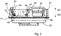
- Figure 2
- is a side view of the grasping mechanism shown without an outer shell;
- Figure 3
- is a top end view of the grasping mechanism shown without the outer shell; and
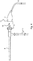
- Figure 4
- is a schematic view illustrating a connection of a camera head having the endoscope eyepiece grasping mechanism of
Figure 1 with an endoscope having an endoscope eyepiece. - Referring to the drawings,
Figure 1 shows a grasping mechanism generally designated 10, which is attached to amounting portion 12 of acamera head chassis 2 shown inFigure 4 . Thegrasping mechanism 10 comprises abase part 20 with a centraleyepiece receiving region 14. - The
base part 20 defines a central light passage opening 18 (Figure 3 ). Thebase part 20 comprises an axially extendingwall 24 which extends fully around the light passage opening 18. Thebase part 20 also includes an innercontoured surface 21 that surrounds and defines the radially inward light passage opening 18. Thecontoured surface 21 is intended and configured to receive anendoscope eyepiece 6 in a coupled position, wherein theendoscope eyepiece 6 is grasped to retain theendoscope eyepiece 6 in thegrasping mechanism 10 to couple anendoscope 4 to thecamera head chassis 2. - The
base part 20 supports at least onetab member 30. In the embodiment shown inFigures 1 - 4 , threetab members 30 are positioned and guided by thebase part 20. The axially extendingwall 24 has a circumferential extent with tab guide regions 22 (threetab guide regions 22 are provided with the embodiment ofFigures 1 - 5). Thetab guide regions 22 have tab openings 28 with tabpin guide configurations 26, comprised of partially radially extending slot guides (angled slots) 25 at each side of each of the tab openings 28. The tab openings 28 and the extendingslot guides 25 are formed in thewall 24. Each of theslot guides 25 define a path extending from a radially inwardlower end 27 to a radially outwardupper end 29. The path between the inwardlower guide end 27 and the outwardupper guide end 29 has a radial component relative to the inward light passage opening 18 based on the circumferential course of thewall 24. - Each
tab member 30 includes a tabguide engagement member 32 in the form of two pins. Onepin 32 extends from each side of each of themember tab 30. Each of thepins 32 is positioned in one of the slot guides 25 of one of theguide regions 22. The slot guides 25 are preferably provided with the same shape and define a region for movement of eachpin 32. This moves thetab member 30 to follow the path of the movement of each pin 33 in therespective slot 25. The shapes of theslots 25 provide a radial path for a radial movement of eachtab member 30 toward thelight passage opening 18 and away from the light passage opening 18 to grasp and retain the endoscope eyepiece in the receivingregion 14. - The grasping
mechanism 10 further includes anannular part 40 with an outer engagement (grasping)surface 42 and acamming surface 44. In the embodiment ofFigures 1 - 4 , theouter engagement surface 42 is provided by anouter shell 43 with a gripping contour and theinner camming surface 44 is provided by aninner housing 41. The two parts (theinner housing 41 and the outer shell 43), are fixedly connected to form theannular part 40. - The
inner housing 41 has an annular shape that includes widenedregions 45 withtab passage openings 46 corresponding to the threetab guide regions 22 of thebase part 20. In an assembled state of the graspingmechanism 10, the widenedregions 45 are radially outward, relative to the centrally located passage opening 18, by a greater distance than reduced dimension (diameter)regions 50 of theinner housing 41. This provides partially radially extendingadjacent regions 47, that each extend radially and circumferentially relative to the widenedregions 45 of larger diameter and the reduceddimension region 50. At theradially extending regions 47 theinner camming surface 44 is provided in the form of slots 48 (Figure 2 ). In the assembled state, eachslot 48 receives one of thepins 32, with theslot 48 forming thecamming surface 44 and thepins 32 being cam followers to follow the path defined by eachslot 48. As shown, theslots 48 extend from a radially inward lower end 51 to a radially outwardupper end 53. With this configuration, eachpin 32 in the associatedslot 48 is moved to a radially inward location of the associated slot guides 25 with thepin 32 at the radially inward lower end 51 of therespective slot 48. With thepin 32 at the radiallyoutward end 53 of therespective slot 48, thepin 32 is moved to a radially outward location of the associated slot guide 25 of thetab guide configuration 26. In the assembled state, movement of theannular part 40 relative to thebase part 20 in a first axial direction AO moves each of thetab members 30 radially outward (Figure 2 ). Further, in the assembled state, movement of theannular part 40 relative to thebase part 20 in a second axial direction AC moves each of thetab members 30 radially inward. In the assembled state, eachtab member 30 is guided and positioned and supported for movement radially relative to theannular part 40, based on eachtab member 30 being aligned with one of thetab passages 46. - A biasing
device 60 is connected to each of thebase part 20 and theannular part 42 to act between thebase part 20 and theannular part 40. The biasingdevice 60 biases theannular part 40 in the axial direction AC toward a final grasping position with which thetab members 30 grasps theendoscope eyepiece 6 to hold the endoscope eyepiece in the centraleyepiece receiving region 14 in contact with the inner contouredsurface 21 so as to couple theeyepiece 6 with thecamera head 2. In the grasping position, eachpin 32 is at a radially innermost position and each pin 33 is at or toward the lower inner end 51 of eachslot 48. In the embodiment shown, the biasing device comprises a plurality of helical compression springs 60. Eachhelical compression spring 60 is seated in aspring seat 64 and extends from thespring seat 64 between aspring receiving contour 66 of theannular part 40 andspring region 49 of theinner housing 41 to the upperannular wall 68 of theouter shell 43. Eachcompression spring 60 acts between therespective spring seat 64 and a respective area of the upperannular wall 68. - For assembling the grasping
device 10, thetab members 30 are each connected topins 32 so one of thepins 32 extends from each side of eachtab member 30. Thepins 32 withconnected tab members 30 are mounted on thebase part 20 with thepins 32 received in one of the slot guides 25 of eachpin guide configuration 26. Theannular part 40 or theinner housing 41 is disposed coaxially with thebase part 20 and pushed axially to capture thebase part 20 within theinner housing 41, with eachtab member 30 disposed in a corresponding one of thetab openings 46 of theinner housing 41. The assembly also captures eachpin 32 in one of theslots 48 of theinner camming surface 44. The helical compression springs 60 are positioned on therespective spring seats 64 and then placed in contact with the inner surface of the upperannular wall 68 of theouter shell 43. A fixing of theouter shell 43 to theinner housing 41 may be performed before or after theinner housing 41 is combined with thebase part 20. The entire assembly of the graspingdevice 10 is attached to thecamera head chassis 2 via a threaded retaining feature of a known fastening mechanism with additional sealing provided byring washer 59. -
Figure 4 shows thecamera head 2 with the endoscopeeyepiece grasping mechanism 10 along with a positionedendoscope 4. Theendoscope 4 has theendoscope eyepiece 6.Figure 4 also shows alight source 7 which can be connected to theendoscope 4 as well as asignal connection line 8 that is connected to thecamera head 2. - As shown in
Figure 4 , theendoscope eyepiece 6 of theendoscope 4 is moved axially toward the graspingmechanism 10 and then is moved into theeyepiece receiving region 14. In operation, theannular part 40 is grasped at theouter engagement surface 42 and is pulled in the direction AO. Theangled slots 48 of theinner housing 41 act on thepins 32 such that thepins 32 each move radially outward along the slot guides 25 and move toward the radiallyoutward end 53 of theangled slots 48. With this relative movement of thepins 32, each of thetab members 30 moves radially outward to a receiving position. After this, theannular part 40 may be released such that the action of the biasingdevice 60 moves theannular part 40 in the direction AC, such the graspingmechanism 10 assumes a grasping position. With this movement in the direction AC theangled slots 48 of theinner housing 41 act on thepins 32 such that theinner pins 32 each move radially inward along the slot guides 25 and move toward the radially inward end 51 of theangled slots 48. Thepins 32 along with thetab members 30 move radially inward to the grasping position in which thetab members 30 engage an outer periphery of theendoscope eyepiece 6, to couple theendoscope eyepiece 6 to thecamera head 2. To release theendoscope eyepiece 6 and theconnected endoscope 4 from thecamera head 2, theannular part 40 is again grasped and pulled in the direction AO to move thetab members 30 radially outwardly to a receiving position, allowing removal of theendoscope eyepiece 6 from theeyepiece receiving region 14. - The
tab members 30 include ramped, shaped or contoured surface features 36 at an inward side, namely within theeyepiece receiving region 14 and facing and surrounding thelight passage opening 18. This configuration allows the surface of theendoscope eyepiece 6 to be moved toward and into the receivingregion 14 resulting in engagement with thetab members 30. Based on the surface of theeyepiece 6 acting on the contoured surface features 36 of thetab members 30, each of thetab members 30 is pressed radially outward to allow insertion of theendoscope eyepiece 6 into the receivingregion 14. This movement and pressing of the tabs results in theannular part 40 being pulled down in the direction AO. This results in theannular part 40 sliding relative to thebase part 20 from the grasping position to the receiving position. When the endoscope eyepiece is fully received in the receivingregion 14, the surface of theeyepiece 6 clears the contoured surface features 36 of thetab members 30 and thetab members 30 again move radially inward with theannular part 40 sliding relative to thebase part 20 from the receiving position to the grasping position to capture and retain theendoscope eyepiece 6 and to maintain theendoscope eyepiece 6 in the coupled position with thecamera head 2. - While specific embodiments of the invention have been shown and described in detail to illustrate the application of the principles of the invention, it will be understood that the invention may be embodied otherwise without departing from such principles.
- The features of the invention as mentioned apply not only in the combinations mentioned but also in other combinations or alone, without leaving the scope of the present invention. Further aspects of the present invention will be apparent from the figures. These figures show examples of the invention. The figures, the description and the requirements contain numerous features in combination. One of skill in the art will recognize the features individually and combine them into meaningful further combinations. An endoscope eyepiece grasping mechanism includes a base part engaging a tab member via a connected engagement member. An annular part has an outer engagement surface and an inner camming surface disposed coaxially with the base part and axially moveable relative to the base part. The engagement surface is moveable with the camming surface to move the tab member radially outwardly, with a movement of the annular part relative to the base part in a first axial direction, toward a receiving position, and to move the tab member radially inwardly, with movement of the annular part relative to the base part in a second axial direction, toward a grasping position. A biasing device acts to bias the annular part toward the grasping position. An endoscope eyepiece is engaged by the tab member upon the annular part moving from the receiving position to the grasping position.
LIST OF REFERENCE CHARACTERS 2 camera head chassis 41 inner housing / annular axially ex-tending wall 4 endoscope 6 endoscope eyepiece 42 outer engagement surface 7 light source 43 outer shell 8 signal connection line 44 camming surface 10 grasping mechanism 45 widened region 12 mounting portion 46 tab member passage 14 central eyepiece receiving region 47 adjacent region 18 light passage opening 48 slot 20 base part 49 spring region 21 contoured surface 50 reduced dimension region 22 tab guide region 51 radially inward lower end 24 axially extending wall 53 radially outward upper end 25 slot guide 59 ring washer 26 tab pin guide configuration 60 biasing device - helical compres-sion springs 27 lower radially inner guide end 28 tab opening 64 spring seat 29 upper radially outer guide end 66 spring receiving contour 30 tab member 68 upper annular wall 32 engagement member (pin) AO first axial direction 36 ramped/contoured surface features AC second axial direction 40 annular part
Claims (12)
- An endoscope eyepiece grasping mechanism (10) for an endoscope camera head (2), the endoscope eyepiece grasping mechanism comprising:- a base part (20) with a central eyepiece receiving region (14) with a light passage opening (18), the base part (20) comprising an axially extending wall (24);- a radially moveable tab member (30) positioned relative to the axially extending wall (24);- an engagement member (32) connected to the tab member (30);- an annular part (40) comprising an outer engagement surface (42) and inner camming surface (44), the annular part (40) being disposed coaxially with the base part (20) and being axially moveable in an axial direction relative to the base part (20), the engagement surface (42) being moveable with said camming surface (44) to move the tab member (30) radially outwardly, with a movement of the annular part (40) relative to the base part (20) in a first axial direction (AO) toward a receiving position, and to move the tab member (30) radially inwardly, with movement of the annular part (40) relative to the base part (20) in a second axial direction (AC) toward a grasping position in which an endoscope eyepiece (6) within the central eyepiece receiving region (14) is grasped by the grasping mechanism (10) to couple the endoscope eyepiece (6) to the endoscope camera head (2); and- a biasing device (60) acting between the base part (20) and the annular part (40) to bias the annular part (40) in the second direction (AC) toward the grasping position, whereby an endoscope eyepiece (6) may be inserted in the central eyepiece receiving region (14) in the receiving position and the endoscope eyepiece is engaged by the tab member (30) and retained in the eyepiece receiving region (14) upon the annular part (40) moving from the receiving position to the grasping position.
- An endoscope eyepiece grasping mechanism (10) according to claim 1, wherein the tab member (30) has a ramped shaped surface (36) configured to be contacted by the endoscope eyepiece (6) with the annular part (40) in the grasping position to push the ramped shaped surface (36) radially outwardly with axial movement of the endoscope eyepiece (6) into the eyepiece receiving region (14), causing movement of the tab member (30) radially outwardly and movement of the annular part (40) toward the receiving position.
- An endoscope eyepiece grasping mechanism (10) according to claim 1 or claim 2, wherein the inner camming surface (44) is formed by an axially extending camming wall portion (41) defining a slot (48).
- An endoscope eyepiece grasping mechanism (10) according to one or more of the preceding claims, wherein:- the engagement member (32) comprises a pin at each side of the tab member (30); and- the axially extending camming wall portion (41) has a circumferential extent with a radially outwardly extending portion defining each slot.
- An endoscope eyepiece grasping mechanism (10) according to one or more of the preceding claims, further comprising at least another tab member (30) with pins (32) to provide a plurality of tab members (30), wherein the axially extending wall (24) of the base part (20) comprises a pin guide configuration (26) adjacent to a tab opening (28).
- An endoscope eyepiece grasping mechanism (10) according to one or more of the preceding claims, wherein:- the axially extending wall (24) extends circumferentially around the light passage opening (18);- the plurality of tab openings (28) are distributed uniformly relative to a circumferential extent of the axially extending wall (24).
- An endoscope eyepiece grasping mechanism (10) according to one or more of the preceding claims, wherein the annular part (40) comprises:- an outer shell (43) with the outer engagement surface (42); and- an inner housing (41) with the inner camming surface (44).
- An endoscope eyepiece grasping mechanism (10) according to one or more of the preceding claims, wherein:- the inner housing comprises an axially extending camming wall portion (41) with an annular shape having widened regions (45) with an extent that is at least partially radial;- the inner camming surface (42) is formed by a slot in each adjacent region (47);- the engagement member comprises a pin (32) at each side of the tab member (30), each pin being received in one said slot (48); and- each widened region (45) has a tab member passage (46).
- An endoscope eyepiece grasping mechanism (10) according to one or more of the preceding claims, wherein the outer shell (43) has a gripping contour configured to facilitate being actuated.
- An endoscope eyepiece grasping mechanism (10) according to one or more of the preceding claims, wherein:- the annular part (40) is formed of metal or plastic; and- the base part (20) is formed of metal or plastic.
- An endoscope camera head (2) comprising:- a camera head chassis; and- an endoscope eyepiece grasping mechanism (10) according to one or more of the preceding claims.
- An endoscope system comprising:- an endoscope (4) with an endoscope eyepiece (6);- a camera head chassis (2); and- an endoscope eyepiece grasping mechanism (10) according to one or more of the preceding claims.
Applications Claiming Priority (1)
| Application Number | Priority Date | Filing Date | Title |
|---|---|---|---|
| US17/353,106 US11766166B2 (en) | 2021-06-21 | 2021-06-21 | Endoscope eyepiece grasping mechanism and endoscope camera head with endoscope eyepiece grasping mechanism |
Publications (2)
| Publication Number | Publication Date |
|---|---|
| EP4108156A1 true EP4108156A1 (en) | 2022-12-28 |
| EP4108156B1 EP4108156B1 (en) | 2025-01-29 |
Family
ID=82117463
Family Applications (1)
| Application Number | Title | Priority Date | Filing Date |
|---|---|---|---|
| EP22179867.1A Active EP4108156B1 (en) | 2021-06-21 | 2022-06-20 | Endoscope eyepiece grasping mechanism and endoscope camera head with endoscope eyepiece grasping mechanism |
Country Status (2)
| Country | Link |
|---|---|
| US (1) | US11766166B2 (en) |
| EP (1) | EP4108156B1 (en) |
Citations (6)
| Publication number | Priority date | Publication date | Assignee | Title |
|---|---|---|---|---|
| JPH0829698A (en) * | 1994-07-15 | 1996-02-02 | Machida Endscope Co Ltd | Connecting device for endoscope |
| JPH119549A (en) * | 1997-06-25 | 1999-01-19 | Union Optical Co Ltd | Camera connector with endoscope |
| US20110317274A1 (en) * | 2010-06-29 | 2011-12-29 | Richard Wolf Gmbh | Coupling device for detachably connecting an eyepiece of an endoscope optical system with a camera lens |
| CN203573025U (en) * | 2012-08-16 | 2014-04-30 | 雪力光纤有限公司 | Eye lens coupling piece |
| EP3143923A1 (en) * | 2014-12-26 | 2017-03-22 | Olympus Corporation | Eyepiece connecting device |
| US20200367728A1 (en) * | 2019-05-21 | 2020-11-26 | Atmos Medizintechnik Gmbh & Co. Kg | Endoscope Coupler for a Camera and Method for Coupling and Decoupling an Endoscope with a Camera by Means of an Endoscope Coupler as well as Camera with Endoscope Coupler |
Family Cites Families (2)
| Publication number | Priority date | Publication date | Assignee | Title |
|---|---|---|---|---|
| JPS5689232A (en) * | 1979-12-24 | 1981-07-20 | Olympus Optical Co | Endoscope apparatus |
| ES2904567T3 (en) * | 2017-12-04 | 2022-04-05 | Promecon Gmbh | Endoscope Camera Coupler |
-
2021
- 2021-06-21 US US17/353,106 patent/US11766166B2/en active Active
-
2022
- 2022-06-20 EP EP22179867.1A patent/EP4108156B1/en active Active
Patent Citations (6)
| Publication number | Priority date | Publication date | Assignee | Title |
|---|---|---|---|---|
| JPH0829698A (en) * | 1994-07-15 | 1996-02-02 | Machida Endscope Co Ltd | Connecting device for endoscope |
| JPH119549A (en) * | 1997-06-25 | 1999-01-19 | Union Optical Co Ltd | Camera connector with endoscope |
| US20110317274A1 (en) * | 2010-06-29 | 2011-12-29 | Richard Wolf Gmbh | Coupling device for detachably connecting an eyepiece of an endoscope optical system with a camera lens |
| CN203573025U (en) * | 2012-08-16 | 2014-04-30 | 雪力光纤有限公司 | Eye lens coupling piece |
| EP3143923A1 (en) * | 2014-12-26 | 2017-03-22 | Olympus Corporation | Eyepiece connecting device |
| US20200367728A1 (en) * | 2019-05-21 | 2020-11-26 | Atmos Medizintechnik Gmbh & Co. Kg | Endoscope Coupler for a Camera and Method for Coupling and Decoupling an Endoscope with a Camera by Means of an Endoscope Coupler as well as Camera with Endoscope Coupler |
Also Published As
| Publication number | Publication date |
|---|---|
| US20220400935A1 (en) | 2022-12-22 |
| EP4108156B1 (en) | 2025-01-29 |
| US11766166B2 (en) | 2023-09-26 |
Similar Documents
| Publication | Publication Date | Title |
|---|---|---|
| US5329887A (en) | Endoscope control assembly with removable control knob/brake assembly | |
| US8945098B2 (en) | Surgical manipulation instrument | |
| CA1305900C (en) | Contamination protection system for endoscope control handles | |
| EP0864900B1 (en) | Quick attach/release adapter mechanism | |
| US4974580A (en) | Endoscope protective member | |
| US6129392A (en) | Coupler for tubular-shaft instruments | |
| CN111973133B (en) | Endoscope connectors for cameras, methods for engaging and disengaging endoscopes and cameras, and cameras | |
| CA2054519A1 (en) | Portable arthroscope with disposable probe | |
| US8854738B2 (en) | Coupling device for detachably connecting an eyepiece of an endoscope optical system with a camera lens | |
| AU2022407868A1 (en) | Optical fiber connector and adapter | |
| EP4108156B1 (en) | Endoscope eyepiece grasping mechanism and endoscope camera head with endoscope eyepiece grasping mechanism | |
| US20200275967A1 (en) | Apparatus for driving a bone fixation pin | |
| JPH05307143A (en) | Externally mounted channel device for endoscope | |
| JP2002330928A (en) | Endoscope system | |
| CN116407285A (en) | Guide wire or catheter controller and surgical robot | |
| CN110051315A (en) | Disposal type endoscope | |
| JP4354043B2 (en) | Endoscope holder | |
| US6299220B1 (en) | Coupling for sealingly connecting two elongate medical instruments | |
| JP3172279B2 (en) | Linear retinoscope | |
| EP4104747A1 (en) | Grasping mechanism for side-loading optical endoscopes and endoscope camera head with endoscope eyepiece grasping mechanism | |
| EP4306034A1 (en) | Endoscope comprising a double brake for up-down and left-right | |
| US11698522B2 (en) | Systems and methods for connecting a light cable to an illuminator | |
| EP2106734A1 (en) | Electric bending endoscope | |
| JP3506999B2 (en) | Endoscope device | |
| US4938692A (en) | Instrument handgrip with a built-in light |
Legal Events
| Date | Code | Title | Description |
|---|---|---|---|
| PUAI | Public reference made under article 153(3) epc to a published international application that has entered the european phase |
Free format text: ORIGINAL CODE: 0009012 |
|
| STAA | Information on the status of an ep patent application or granted ep patent |
Free format text: STATUS: THE APPLICATION HAS BEEN PUBLISHED |
|
| AK | Designated contracting states |
Kind code of ref document: A1 Designated state(s): AL AT BE BG CH CY CZ DE DK EE ES FI FR GB GR HR HU IE IS IT LI LT LU LV MC MK MT NL NO PL PT RO RS SE SI SK SM TR |
|
| STAA | Information on the status of an ep patent application or granted ep patent |
Free format text: STATUS: REQUEST FOR EXAMINATION WAS MADE |
|
| P01 | Opt-out of the competence of the unified patent court (upc) registered |
Effective date: 20230527 |
|
| 17P | Request for examination filed |
Effective date: 20230628 |
|
| RBV | Designated contracting states (corrected) |
Designated state(s): AL AT BE BG CH CY CZ DE DK EE ES FI FR GB GR HR HU IE IS IT LI LT LU LV MC MK MT NL NO PL PT RO RS SE SI SK SM TR |
|
| GRAP | Despatch of communication of intention to grant a patent |
Free format text: ORIGINAL CODE: EPIDOSNIGR1 |
|
| STAA | Information on the status of an ep patent application or granted ep patent |
Free format text: STATUS: GRANT OF PATENT IS INTENDED |
|
| INTG | Intention to grant announced |
Effective date: 20240912 |
|
| GRAS | Grant fee paid |
Free format text: ORIGINAL CODE: EPIDOSNIGR3 |
|
| GRAA | (expected) grant |
Free format text: ORIGINAL CODE: 0009210 |
|
| STAA | Information on the status of an ep patent application or granted ep patent |
Free format text: STATUS: THE PATENT HAS BEEN GRANTED |
|
| AK | Designated contracting states |
Kind code of ref document: B1 Designated state(s): AL AT BE BG CH CY CZ DE DK EE ES FI FR GB GR HR HU IE IS IT LI LT LU LV MC MK MT NL NO PL PT RO RS SE SI SK SM TR |
|
| REG | Reference to a national code |
Ref country code: GB Ref legal event code: FG4D |
|
| REG | Reference to a national code |
Ref country code: CH Ref legal event code: EP |
|
| REG | Reference to a national code |
Ref country code: DE Ref legal event code: R096 Ref document number: 602022009989 Country of ref document: DE |
|
| REG | Reference to a national code |
Ref country code: IE Ref legal event code: FG4D |
|
| REG | Reference to a national code |
Ref country code: NL Ref legal event code: MP Effective date: 20250129 |
|
| PG25 | Lapsed in a contracting state [announced via postgrant information from national office to epo] |
Ref country code: NL Free format text: LAPSE BECAUSE OF FAILURE TO SUBMIT A TRANSLATION OF THE DESCRIPTION OR TO PAY THE FEE WITHIN THE PRESCRIBED TIME-LIMIT Effective date: 20250129 |
|
| PG25 | Lapsed in a contracting state [announced via postgrant information from national office to epo] |
Ref country code: RS Free format text: LAPSE BECAUSE OF FAILURE TO SUBMIT A TRANSLATION OF THE DESCRIPTION OR TO PAY THE FEE WITHIN THE PRESCRIBED TIME-LIMIT Effective date: 20250429 |
|
| PG25 | Lapsed in a contracting state [announced via postgrant information from national office to epo] |
Ref country code: FI Free format text: LAPSE BECAUSE OF FAILURE TO SUBMIT A TRANSLATION OF THE DESCRIPTION OR TO PAY THE FEE WITHIN THE PRESCRIBED TIME-LIMIT Effective date: 20250129 |
|
| PG25 | Lapsed in a contracting state [announced via postgrant information from national office to epo] |
Ref country code: PL Free format text: LAPSE BECAUSE OF FAILURE TO SUBMIT A TRANSLATION OF THE DESCRIPTION OR TO PAY THE FEE WITHIN THE PRESCRIBED TIME-LIMIT Effective date: 20250129 |
|
| PGFP | Annual fee paid to national office [announced via postgrant information from national office to epo] |
Ref country code: DE Payment date: 20250626 Year of fee payment: 4 |
|
| PG25 | Lapsed in a contracting state [announced via postgrant information from national office to epo] |
Ref country code: ES Free format text: LAPSE BECAUSE OF FAILURE TO SUBMIT A TRANSLATION OF THE DESCRIPTION OR TO PAY THE FEE WITHIN THE PRESCRIBED TIME-LIMIT Effective date: 20250129 |
|
| REG | Reference to a national code |
Ref country code: LT Ref legal event code: MG9D |
|
| PG25 | Lapsed in a contracting state [announced via postgrant information from national office to epo] |
Ref country code: NO Free format text: LAPSE BECAUSE OF FAILURE TO SUBMIT A TRANSLATION OF THE DESCRIPTION OR TO PAY THE FEE WITHIN THE PRESCRIBED TIME-LIMIT Effective date: 20250429 Ref country code: IS Free format text: LAPSE BECAUSE OF FAILURE TO SUBMIT A TRANSLATION OF THE DESCRIPTION OR TO PAY THE FEE WITHIN THE PRESCRIBED TIME-LIMIT Effective date: 20250529 |
|
| REG | Reference to a national code |
Ref country code: AT Ref legal event code: MK05 Ref document number: 1762600 Country of ref document: AT Kind code of ref document: T Effective date: 20250129 |
|
| PG25 | Lapsed in a contracting state [announced via postgrant information from national office to epo] |
Ref country code: HR Free format text: LAPSE BECAUSE OF FAILURE TO SUBMIT A TRANSLATION OF THE DESCRIPTION OR TO PAY THE FEE WITHIN THE PRESCRIBED TIME-LIMIT Effective date: 20250129 |
|
| PG25 | Lapsed in a contracting state [announced via postgrant information from national office to epo] |
Ref country code: PT Free format text: LAPSE BECAUSE OF FAILURE TO SUBMIT A TRANSLATION OF THE DESCRIPTION OR TO PAY THE FEE WITHIN THE PRESCRIBED TIME-LIMIT Effective date: 20250529 Ref country code: LV Free format text: LAPSE BECAUSE OF FAILURE TO SUBMIT A TRANSLATION OF THE DESCRIPTION OR TO PAY THE FEE WITHIN THE PRESCRIBED TIME-LIMIT Effective date: 20250129 |
|
| PGFP | Annual fee paid to national office [announced via postgrant information from national office to epo] |
Ref country code: FR Payment date: 20250624 Year of fee payment: 4 |
|
| PG25 | Lapsed in a contracting state [announced via postgrant information from national office to epo] |
Ref country code: GR Free format text: LAPSE BECAUSE OF FAILURE TO SUBMIT A TRANSLATION OF THE DESCRIPTION OR TO PAY THE FEE WITHIN THE PRESCRIBED TIME-LIMIT Effective date: 20250430 Ref country code: BG Free format text: LAPSE BECAUSE OF FAILURE TO SUBMIT A TRANSLATION OF THE DESCRIPTION OR TO PAY THE FEE WITHIN THE PRESCRIBED TIME-LIMIT Effective date: 20250129 |
|
| PG25 | Lapsed in a contracting state [announced via postgrant information from national office to epo] |
Ref country code: AT Free format text: LAPSE BECAUSE OF FAILURE TO SUBMIT A TRANSLATION OF THE DESCRIPTION OR TO PAY THE FEE WITHIN THE PRESCRIBED TIME-LIMIT Effective date: 20250129 |
|
| PG25 | Lapsed in a contracting state [announced via postgrant information from national office to epo] |
Ref country code: SE Free format text: LAPSE BECAUSE OF FAILURE TO SUBMIT A TRANSLATION OF THE DESCRIPTION OR TO PAY THE FEE WITHIN THE PRESCRIBED TIME-LIMIT Effective date: 20250129 |
|
| PG25 | Lapsed in a contracting state [announced via postgrant information from national office to epo] |
Ref country code: SM Free format text: LAPSE BECAUSE OF FAILURE TO SUBMIT A TRANSLATION OF THE DESCRIPTION OR TO PAY THE FEE WITHIN THE PRESCRIBED TIME-LIMIT Effective date: 20250129 |
|
| PG25 | Lapsed in a contracting state [announced via postgrant information from national office to epo] |
Ref country code: DK Free format text: LAPSE BECAUSE OF FAILURE TO SUBMIT A TRANSLATION OF THE DESCRIPTION OR TO PAY THE FEE WITHIN THE PRESCRIBED TIME-LIMIT Effective date: 20250129 |
|
| PGFP | Annual fee paid to national office [announced via postgrant information from national office to epo] |
Ref country code: IT Payment date: 20250630 Year of fee payment: 4 |
|
| PG25 | Lapsed in a contracting state [announced via postgrant information from national office to epo] |
Ref country code: CZ Free format text: LAPSE BECAUSE OF FAILURE TO SUBMIT A TRANSLATION OF THE DESCRIPTION OR TO PAY THE FEE WITHIN THE PRESCRIBED TIME-LIMIT Effective date: 20250129 Ref country code: EE Free format text: LAPSE BECAUSE OF FAILURE TO SUBMIT A TRANSLATION OF THE DESCRIPTION OR TO PAY THE FEE WITHIN THE PRESCRIBED TIME-LIMIT Effective date: 20250129 |
|
| PG25 | Lapsed in a contracting state [announced via postgrant information from national office to epo] |
Ref country code: RO Free format text: LAPSE BECAUSE OF FAILURE TO SUBMIT A TRANSLATION OF THE DESCRIPTION OR TO PAY THE FEE WITHIN THE PRESCRIBED TIME-LIMIT Effective date: 20250129 |
|
| PG25 | Lapsed in a contracting state [announced via postgrant information from national office to epo] |
Ref country code: SK Free format text: LAPSE BECAUSE OF FAILURE TO SUBMIT A TRANSLATION OF THE DESCRIPTION OR TO PAY THE FEE WITHIN THE PRESCRIBED TIME-LIMIT Effective date: 20250129 |
|
| REG | Reference to a national code |
Ref country code: DE Ref legal event code: R097 Ref document number: 602022009989 Country of ref document: DE |
|
| PLBE | No opposition filed within time limit |
Free format text: ORIGINAL CODE: 0009261 |
|
| STAA | Information on the status of an ep patent application or granted ep patent |
Free format text: STATUS: NO OPPOSITION FILED WITHIN TIME LIMIT |
|
| REG | Reference to a national code |
Ref country code: CH Ref legal event code: L10 Free format text: ST27 STATUS EVENT CODE: U-0-0-L10-L00 (AS PROVIDED BY THE NATIONAL OFFICE) Effective date: 20251210 |
|
| 26N | No opposition filed |
Effective date: 20251030 |
|
| REG | Reference to a national code |
Ref country code: CH Ref legal event code: H13 Free format text: ST27 STATUS EVENT CODE: U-0-0-H10-H13 (AS PROVIDED BY THE NATIONAL OFFICE) Effective date: 20260127 |
|
| PG25 | Lapsed in a contracting state [announced via postgrant information from national office to epo] |
Ref country code: MC Free format text: LAPSE BECAUSE OF FAILURE TO SUBMIT A TRANSLATION OF THE DESCRIPTION OR TO PAY THE FEE WITHIN THE PRESCRIBED TIME-LIMIT Effective date: 20250129 |
|
| PG25 | Lapsed in a contracting state [announced via postgrant information from national office to epo] |
Ref country code: LU Free format text: LAPSE BECAUSE OF NON-PAYMENT OF DUE FEES Effective date: 20250620 |
|
| REG | Reference to a national code |
Ref country code: BE Ref legal event code: MM Effective date: 20250630 |
|
| PG25 | Lapsed in a contracting state [announced via postgrant information from national office to epo] |
Ref country code: IE Free format text: LAPSE BECAUSE OF NON-PAYMENT OF DUE FEES Effective date: 20250620 |
|
| PG25 | Lapsed in a contracting state [announced via postgrant information from national office to epo] |
Ref country code: BE Free format text: LAPSE BECAUSE OF NON-PAYMENT OF DUE FEES Effective date: 20250630 |
|
| PG25 | Lapsed in a contracting state [announced via postgrant information from national office to epo] |
Ref country code: CH Free format text: LAPSE BECAUSE OF NON-PAYMENT OF DUE FEES Effective date: 20250630 |