EP4108127A1 - Hair care device - Google Patents
Hair care device Download PDFInfo
- Publication number
- EP4108127A1 EP4108127A1 EP21756934.2A EP21756934A EP4108127A1 EP 4108127 A1 EP4108127 A1 EP 4108127A1 EP 21756934 A EP21756934 A EP 21756934A EP 4108127 A1 EP4108127 A1 EP 4108127A1
- Authority
- EP
- European Patent Office
- Prior art keywords
- hair care
- care device
- controller
- pump
- detector
- Prior art date
- Legal status (The legal status is an assumption and is not a legal conclusion. Google has not performed a legal analysis and makes no representation as to the accuracy of the status listed.)
- Granted
Links
Images

Classifications
-
- B—PERFORMING OPERATIONS; TRANSPORTING
- B05—SPRAYING OR ATOMISING IN GENERAL; APPLYING FLUENT MATERIALS TO SURFACES, IN GENERAL
- B05B—SPRAYING APPARATUS; ATOMISING APPARATUS; NOZZLES
- B05B7/00—Spraying apparatus for discharge of liquids or other fluent materials from two or more sources, e.g. of liquid and air, of powder and gas
- B05B7/0075—Nozzle arrangements in gas streams
-
- A—HUMAN NECESSITIES
- A45—HAND OR TRAVELLING ARTICLES
- A45D—HAIRDRESSING OR SHAVING EQUIPMENT; EQUIPMENT FOR COSMETICS OR COSMETIC TREATMENTS, e.g. FOR MANICURING OR PEDICURING
- A45D20/00—Hair drying devices; Accessories therefor
- A45D20/04—Hot-air producers
- A45D20/08—Hot-air producers heated electrically
- A45D20/10—Hand-held drying devices, e.g. air douches
- A45D20/12—Details thereof or accessories therefor, e.g. nozzles, stands
-
- A—HUMAN NECESSITIES
- A45—HAND OR TRAVELLING ARTICLES
- A45D—HAIRDRESSING OR SHAVING EQUIPMENT; EQUIPMENT FOR COSMETICS OR COSMETIC TREATMENTS, e.g. FOR MANICURING OR PEDICURING
- A45D34/00—Containers or accessories specially adapted for handling liquid toiletry or cosmetic substances, e.g. perfumes
- A45D34/04—Appliances specially adapted for applying liquid, e.g. using roller or ball
-
- B—PERFORMING OPERATIONS; TRANSPORTING
- B05—SPRAYING OR ATOMISING IN GENERAL; APPLYING FLUENT MATERIALS TO SURFACES, IN GENERAL
- B05B—SPRAYING APPARATUS; ATOMISING APPARATUS; NOZZLES
- B05B12/00—Arrangements for controlling delivery; Arrangements for controlling the spray area
- B05B12/08—Arrangements for controlling delivery; Arrangements for controlling the spray area responsive to condition of liquid or other fluent material to be discharged, of ambient medium or of target ; responsive to condition of spray devices or of supply means, e.g. pipes, pumps or their drive means
-
- B—PERFORMING OPERATIONS; TRANSPORTING
- B05—SPRAYING OR ATOMISING IN GENERAL; APPLYING FLUENT MATERIALS TO SURFACES, IN GENERAL
- B05B—SPRAYING APPARATUS; ATOMISING APPARATUS; NOZZLES
- B05B12/00—Arrangements for controlling delivery; Arrangements for controlling the spray area
- B05B12/08—Arrangements for controlling delivery; Arrangements for controlling the spray area responsive to condition of liquid or other fluent material to be discharged, of ambient medium or of target ; responsive to condition of spray devices or of supply means, e.g. pipes, pumps or their drive means
- B05B12/12—Arrangements for controlling delivery; Arrangements for controlling the spray area responsive to condition of liquid or other fluent material to be discharged, of ambient medium or of target ; responsive to condition of spray devices or of supply means, e.g. pipes, pumps or their drive means responsive to conditions of ambient medium or target, e.g. humidity, temperature position or movement of the target relative to the spray apparatus
- B05B12/126—Arrangements for controlling delivery; Arrangements for controlling the spray area responsive to condition of liquid or other fluent material to be discharged, of ambient medium or of target ; responsive to condition of spray devices or of supply means, e.g. pipes, pumps or their drive means responsive to conditions of ambient medium or target, e.g. humidity, temperature position or movement of the target relative to the spray apparatus responsive to target velocity, e.g. to relative velocity between spray apparatus and target
-
- B—PERFORMING OPERATIONS; TRANSPORTING
- B05—SPRAYING OR ATOMISING IN GENERAL; APPLYING FLUENT MATERIALS TO SURFACES, IN GENERAL
- B05B—SPRAYING APPARATUS; ATOMISING APPARATUS; NOZZLES
- B05B7/00—Spraying apparatus for discharge of liquids or other fluent materials from two or more sources, e.g. of liquid and air, of powder and gas
- B05B7/0081—Apparatus supplied with low pressure gas, e.g. "hvlp"-guns; air supplied by a fan
-
- B—PERFORMING OPERATIONS; TRANSPORTING
- B05—SPRAYING OR ATOMISING IN GENERAL; APPLYING FLUENT MATERIALS TO SURFACES, IN GENERAL
- B05B—SPRAYING APPARATUS; ATOMISING APPARATUS; NOZZLES
- B05B7/00—Spraying apparatus for discharge of liquids or other fluent materials from two or more sources, e.g. of liquid and air, of powder and gas
- B05B7/24—Spraying apparatus for discharge of liquids or other fluent materials from two or more sources, e.g. of liquid and air, of powder and gas with means, e.g. a container, for supplying liquid or other fluent material to a discharge device
- B05B7/2402—Apparatus to be carried on or by a person, e.g. by hand; Apparatus comprising containers fixed to the discharge device
- B05B7/2464—Apparatus to be carried on or by a person, e.g. by hand; Apparatus comprising containers fixed to the discharge device a liquid being fed by mechanical pumping from the container to the nozzle
-
- B—PERFORMING OPERATIONS; TRANSPORTING
- B05—SPRAYING OR ATOMISING IN GENERAL; APPLYING FLUENT MATERIALS TO SURFACES, IN GENERAL
- B05B—SPRAYING APPARATUS; ATOMISING APPARATUS; NOZZLES
- B05B9/00—Spraying apparatus for discharge of liquids or other fluent material, without essentially mixing with gas or vapour
- B05B9/03—Spraying apparatus for discharge of liquids or other fluent material, without essentially mixing with gas or vapour characterised by means for supplying liquid or other fluent material
- B05B9/04—Spraying apparatus for discharge of liquids or other fluent material, without essentially mixing with gas or vapour characterised by means for supplying liquid or other fluent material with pressurised or compressible container; with pump
- B05B9/08—Apparatus to be carried on or by a person, e.g. of knapsack type
- B05B9/085—Apparatus to be carried on or by a person, e.g. of knapsack type with a liquid pump
- B05B9/0855—Apparatus to be carried on or by a person, e.g. of knapsack type with a liquid pump the pump being motor-driven
- B05B9/0861—Apparatus to be carried on or by a person, e.g. of knapsack type with a liquid pump the pump being motor-driven the motor being electric
-
- A—HUMAN NECESSITIES
- A45—HAND OR TRAVELLING ARTICLES
- A45D—HAIRDRESSING OR SHAVING EQUIPMENT; EQUIPMENT FOR COSMETICS OR COSMETIC TREATMENTS, e.g. FOR MANICURING OR PEDICURING
- A45D1/00—Curling-tongs, i.e. tongs for use when hot; Curling-irons, i.e. irons for use when hot; Accessories therefor
- A45D2001/008—Curling-tongs, i.e. tongs for use when hot; Curling-irons, i.e. irons for use when hot; Accessories therefor with vapor generation, e.g. steam
-
- A—HUMAN NECESSITIES
- A45—HAND OR TRAVELLING ARTICLES
- A45D—HAIRDRESSING OR SHAVING EQUIPMENT; EQUIPMENT FOR COSMETICS OR COSMETIC TREATMENTS, e.g. FOR MANICURING OR PEDICURING
- A45D2200/00—Details not otherwise provided for in A45D
- A45D2200/05—Details of containers
- A45D2200/054—Means for supplying liquid to the outlet of the container
- A45D2200/057—Spray nozzles; Generating atomised liquid
-
- B—PERFORMING OPERATIONS; TRANSPORTING
- B05—SPRAYING OR ATOMISING IN GENERAL; APPLYING FLUENT MATERIALS TO SURFACES, IN GENERAL
- B05B—SPRAYING APPARATUS; ATOMISING APPARATUS; NOZZLES
- B05B7/00—Spraying apparatus for discharge of liquids or other fluent materials from two or more sources, e.g. of liquid and air, of powder and gas
- B05B7/02—Spray pistols; Apparatus for discharge
- B05B7/04—Spray pistols; Apparatus for discharge with arrangements for mixing liquids or other fluent materials before discharge
- B05B7/0416—Spray pistols; Apparatus for discharge with arrangements for mixing liquids or other fluent materials before discharge with arrangements for mixing one gas and one liquid
- B05B7/0441—Spray pistols; Apparatus for discharge with arrangements for mixing liquids or other fluent materials before discharge with arrangements for mixing one gas and one liquid with one inner conduit of liquid surrounded by an external conduit of gas upstream the mixing chamber
- B05B7/045—Spray pistols; Apparatus for discharge with arrangements for mixing liquids or other fluent materials before discharge with arrangements for mixing one gas and one liquid with one inner conduit of liquid surrounded by an external conduit of gas upstream the mixing chamber the gas and liquid flows being parallel just upstream the mixing chamber
Definitions
- the present disclosure relates to a hair care device.
- a hair care device is required to appropriately spray a cosmetic component.
- a hair care device described in PTL 1 detects an inclination in a vertical direction of the hair care device and controls a pump that sends out a cosmetic component based on the inclination to appropriately spray the cosmetic component.
- a user sprays the cosmetic component from the root to the tip of the hair, and thus there is a case where the user swings the hair care device in a short cycle.
- assumed amount and range of spraying the cosmetic component possibly deviate from the actual amount and range of spraying the cosmetic component.
- the present disclosure addresses the foregoing problem, and an object thereof is to provide a hair care device that suitably sprays a cosmetic component.
- a hair care device is a hair care device including a tank that stores a liquid, a pump that outputs the liquid stored in the tank, and a controller that controls an output of the pump, the hair care device further including a detector that detects swing of the hair care device, in which the controller adjusts the output of the pump based on a detection value of the detector.
- the cosmetic component can be suitably sprayed.
- a hair care device is a hair care device including a tank that stores a liquid, a pump that outputs the liquid stored in the tank, and a controller that controls an output of the pump, the hair care device further including a detector that detects swing of the hair care device, in which the controller adjusts the output of the pump based on a detection value of the detector.
- the cosmetic component can be suitably sprayed.
- the detector detects an angular velocity of the hair care device.
- the output of the pump can be controlled using the angular velocity.
- the controller decreases the output of the pump as the angular velocity of the hair care device increases.
- the liquid can be appropriately output.
- the hair care device further includes an air blower that outputs gas and includes a motor and a fan, in which the controller adjusts an output of the motor based on the detection value of the detector.
- the control can be suitably executed.
- the detector detects the angular velocity of the hair care device, and the controller increases the output of the motor as the angular velocity of the hair care device increases.
- an amount of air blow is increased when the angular velocity is large. Therefore, usability is improved.
- Hair care device 10 of a first exemplary embodiment supplies at least one of a cosmetic component and air to the hair or the like of a user.
- Hair care device 10 is, for example, a dryer.
- Hair care device 10 includes housing 11 that constitutes the appearance of hair care device 10 and houses at least one of the other elements that constitute hair care device 10, and grip 12 that is gripped by the user in use.
- Housing 11 and grip 12 are preferably connected to each other by a connector configured to be able to change a position of housing 11 with respect to grip 12.
- Housing 11 and grip 12 are made of any material having excellent heat resistance. In one example, the material constituting housing 11 and grip 12 is polycarbonate.
- Housing 11 includes suction port 11A through which the external air flows in and discharge port 11B through which the cosmetic component or the air is discharged to the outside.
- Suction port 11A preferably includes a filter that prevents dust or the like in the outside air from entering housing 11.
- Suction port 11A and discharge port 11B each have, for example, an elliptical shape.
- Housing 11 includes flow path 13 in which a fluid flow is formed.
- Flow path 13 connects suction port 11A and discharge port 11B.
- Flow path 13 includes first flow path 13A through which mainly gas passes and second flow path 13B through which mainly cosmetic components pass.
- the length of each of first flow path 13A and second flow path 13B is half the length of the entire length of flow path 13.
- Hair care device 10 further includes controller 20, storage 30, operation unit 40, detector 50, power supply unit 60, air blower 70, heating unit 80, and mist generator 90. At least one of controller 20, storage 30, operation unit 40, detector 50, power supply unit 60, air blower 70, heating unit 80, and mist generator 90 is held inside housing 11.
- Controller 20 is constituted of an arithmetic processing unit that executes a control program.
- the arithmetic processing unit is constituted of, for example, at least one or both of a central processing unit (CPU) and a micro processing unit (MPU).
- Controller 20 is configured to be able to communicate with storage 30, operation unit 40, detector 50, air blower 70, heating unit 80, and mist generator 90 in a wireless or wired manner.
- Controller 20 starts control when, for example, power is supplied from power supply unit 60 and an operation signal is input from operation unit 40.
- controller 20 is provided at a position away from heating unit 80 as a heat generation source.
- controller 20 is provided at a location corresponding to grip 12.
- Storage 30 stores program information and table information for executing various controls executed by controller 20.
- the table information is information in which a detection value detected by detector 50 is associated with appropriate amounts of output of air blower 70 and mist generator 90.
- Storage 30 includes, for example, a non-volatile memory and a volatile memory. Storage 30 is provided in the same control circuit as, for example, controller 20.
- Operation unit 40 outputs an operation signal by, for example, an operation from the user to controller 20.
- the operation signal includes a signal for switching on and off of controller 20 or a signal for changing the output of at least one of air blower 70, heating unit 80, and mist generator 90 by controller 20.
- a part of operation unit 40 is configured to protrude toward the outside of housing 11 to allow the user to operate easily.
- Operation unit 40 is constituted of, for example, a button, a switch, and a dial.
- Operation unit 40 may be constituted of a touch panel. Operation unit 40 is mounted on, for example, grip 12.
- Detector 50 detects various pieces of information on hair care device 10.
- the detection value detected by detector 50 is output to controller 20.
- detector 50 is constituted of an acceleration sensor or a gyro sensor, and detects movement of hair care device 10 in three axial directions. Specifically, detector 50 detects acceleration or angular velocity.
- detector 50 is preferably disposed in second flow path 13B.
- detector 50 detects torque of motors provided in air blower 70 and mist generator 90.
- detector 50 is constituted of a torque sensor.
- detector 50 may be configured to detect counter electromotive force.
- detector 50 is a microcomputer that controls a motor.
- Controller 20 calculates the rotation speed and the load torque of the motor from the counter electromotive force.
- detector 50 detects the number of times used and a usage time period of hair care device 10.
- Detector 50 includes a configuration of at least one of the first example and the second example. More preferably, detector 50 includes all the configurations of detector 50 from the first to third examples.
- Power supply unit 60 supplies power to controller 20, storage 30, operation unit 40, detector 50, air blower 70, heating unit 80, and mist generator 90.
- power supply unit 60 is an external power supply such as a commercial power supply.
- Power supply unit 60 may have a configuration of a secondary battery provided inside housing 11. When power supply unit 60 is the external power supply, hair care device 10 and power supply unit 60 are connected by power line 61.
- Air blower 70 forms a flow that sucks the air from suction port 11A and discharges the air from discharge port 11B.
- Air blower 70 includes motor 71 and fan 72. When motor 71 is driven to rotate fan 72, an air flow is generated in flow path 13. Motor 71 is controlled by controller 20. Air blower 70 is located upstream of first flow path 13A and second flow path 13B in flow path 13, and supplies the air to both first flow path 13A and second flow path 13B.
- Heating unit 80 heats the air in housing 11 to produce hot air.
- the hot air is, for example, the air within a range of 100°C to 120°C inclusive.
- Heating unit 80 includes heater 81.
- An example of heater 81 includes a positive temperature coefficient (PTC) heater or an infrared heater.
- Heating unit 80 is provided, for example, in first flow path 13A. Controller 20 controls the output of heater 81.
- PTC positive temperature coefficient
- Mist generator 90 forms the cosmetic component in a mist form.
- the cosmetic component is a liquid or a component contained in a liquid.
- Mist generator 90 includes pump 91, tank 92, and nozzle 93.
- Pump 91 is a liquid pump that supplies the cosmetic component stored in tank 92 to nozzle 93 by driving a motor (not shown).
- the liquid pump is, for example, a gear pump.
- Tank 92 stores the liquid containing the cosmetic component in the inside of hair care device 10.
- Tank 92 is made of any material suitable for holding the liquid containing the cosmetic component. Examples include at least one of polyethylene, polypropylene, polyvinylidene chloride, nylon, polyethylene terephthalate, an ethylene vinyl alcohol copolymer, polyvinyl alcohol, and aluminum.
- Nozzle 93 forms the cosmetic component, which is a liquid, in a mist form.
- Nozzle 93 is made of resin or metal.
- Nozzle 93 includes a plurality of minute holes.
- the cosmetic component of the liquid supplied by pump 91 passes through the minute holes, the cosmetic component is generated in a mist form.
- the cosmetic component and the gas are mixed inside nozzle 93 to generate the cosmetic component in a mist form by shearing force.
- pump 91 further includes a gas pump.
- the gas pump is, for example, a diaphragm pump.
- the cosmetic component contains at least one of: amino acids such as glycine, alanine, valine, leucine, isoleucine, phenylalanine, proline, hydroxyproline, threonine, serine, tyrosine, methionine, tryptophan, cystine, cysteic acid, arginine, histidine, lysine, hydroxylysine, and glutamic acid; higher fatty acids such as capric acid, lauric acid, myristic acid, palmitic acid, stearic acid, behenic acid, oleic acid, coconut oil fatty acid, isostearic acid, isopalmitic acid, and ⁇ -linolenic acid; hydrocarbon oils such as liquid paraffin, liquid isoparaffin, vaseline, squalene, and squalane; natural oils such as camellia oil, macadamia oil, corn oil, olive oil, avocado oil, castor oil, safflower oil, jojoba oil
- controller 20 First control executed by controller 20 is described with reference to Fig. 4 .
- the first control is control executed by controller 20 at predetermined intervals when the user uses hair care device 10.
- Detector 50 includes a configuration of detector 50 of at least the first example.
- controller 20 acquires angular velocity information including the angular velocity of hair care device 10 from detector 50.
- controller 20 compares the angular velocity information with table information stored in storage 30.
- the table information stores outputs of air blower 70 and mist generator 90 appropriate for the angular velocity of hair care device 10 in association with experimentally obtained results. Specifically, when the angular velocity is large, controller 20 reduces the output of the motor of mist generator 90 and supply capability of pump 91, and controls an amount of mist output from second flow path 13B to be small. When the angular velocity is large, controller 20 increases the output of motor 71 of air blower 70 to increase the air volume output from first flow path 13A.
- step S13 controller 20 determines a first output value of pump 91 of mist generator 90 and a second output value of motor 71 of air blower 70 from the table information.
- step S14 controller 20 controls to make the output of pump 91 of mist generator 90 become the first output value and the output of motor 71 of air blower 70 become the second output value. After completion of step S14, controller 20 ends the control.
- Controller 20 controls the output of pump 91 of mist generator 90 and the output of motor 71 of air blower 70 in accordance with the operation of hair care device 10 by the user.
- Hair care device 10 of a second exemplary embodiment is different from hair care device 10 of the first exemplary embodiment in that detector 50 includes the configuration of the second example, and controller 20 performs control based on a detection value of detector 50 of the second example. A part or all of the description of the configuration similar to that of hair care device 10 of the first exemplary embodiment may be omitted.
- Controller 20 executes control based on a value of a torque sensor configured as detector 50.
- the torque sensor detects torque of a motor provided in hair care device 10.
- detector 50 detects the torque of a motor constituting pump 91 of mist generator 90.
- Pump 91 includes liquid feed pump 910 that supplies the cosmetic component from tank 92 to nozzle 93 and air blower pump 920 that supplies gas to nozzle 93.
- Liquid feed pump 910 is, for example, a gear pump.
- Air blower pump 920 is, for example, a diaphragm pump.
- Second control executed by controller 20 is described with reference to Fig. 5 .
- the second control is control for determining a first output value of liquid feed pump 910 and a second output value of air blower pump 920 constituting pump 91 of mist generator 90 during a predetermined period from the start of use of hair care device 10. Controller 20 executes the process of step S21 when pump 91 operates.
- step S21 controller 20 acquires torque value information from detector 50. Specifically, the torque value information of the motor of liquid feed pump 910 is detected. In the case where the torque value information is acquired over time and the torque exceeds the first maximum value, controller 20 proceeds to the process of step S22.
- controller 20 compares the torque value information with table information stored in storage 30.
- the table information is information in which the torque value information experimentally obtained in advance is associated with the type of the cosmetic component. Specifically, the higher the viscosity of the cosmetic component, the higher the torque value, and the lower the viscosity of the cosmetic component, the lower the torque value. Controller 20 estimates the cosmetic component stored in tank 92 of hair care device 10 from the table information, and determines the type of the cosmetic component.
- controller 20 determines the first output value and the second output value of pump 91 based on the determined type of the cosmetic component. Specifically, controller 20 determines the first output value that is the torque of the motor of liquid feed pump 910 and the second output value that is the torque of the motor of air blower pump 920. In step S24, controller 20 controls to make the outputs of the motor of pump 91 of mist generator 90 become the first output value and the second output value. After completion of step S24, controller 20 ends the control.
- Controller 20 determines the type of the cosmetic component, and controls the output of pump 91 of mist generator 90 according to the type of the cosmetic component used by the user.
- Hair care device 10 according to a third exemplary embodiment is different from hair care device 10 according to the second exemplary embodiment in that table information stored in storage 30 does not include types of cosmetic components. A part or all of the description of the configuration similar to that of hair care device 10 of the first exemplary embodiment and the second exemplary embodiment may be omitted.
- Controller 20 detects torque of a motor of liquid feed pump 910 and torque of a motor of air blower pump 920 from detector 50 of the second example, and executes third control for determining a first output value and a second output value of pump 91 based on the detected torque value information.
- Controller 20 acquires the torque and the rotation speed of the motor of liquid feed pump 910 from detector 50 simultaneously with the start of liquid feed pump 910. Controller 20 increases the output of liquid feed pump 910 until the rotation speed of liquid feeding pump 910 reaches a predetermined rotation speed.
- An optional rotation speed is set as the predetermined rotation speed. For example, the rotation speed is set to the rotation speed in the case of supplying pure water to nozzle 93 by liquid feed pump 910.
- Controller 20 starts the motor of air blower pump 920 and estimates the load torque of the motor of air blower pump 920.
- the load torque is estimated based on the counter electromotive force detected by detector 50.
- Controller 20 sets an input voltage of the motor of air blower pump 920 in which a fluctuation range of the load torque is less than or equal to a certain value. When the size of the mist of the cosmetic component is not appropriate, the fluctuation range of the load torque increases. Because the rotation speed of the motor of liquid feed pump 910 increases by the output of air blower pump 920, controller 20 decreases the output of liquid feed pump 910 until the rotation speed of the motor of liquid feed pump 910 reaches a predetermined rotation speed. Controller 20 respectively drives the motor of liquid feed pump 910 and the motor of air blower pump 920 at suitable rotation speeds. Controller 20 repeatedly executes the third control while hair care device 10 is in operation.
- hair care device 10 of the third exemplary embodiment the following effect can be obtained.
- Controller 20 can execute appropriate output based on the detection values of the motors of liquid feed pump 910 and air blower pump 920. Therefore, even when the type of cosmetic component cannot be identified, the output of pump 91 can be suitably controlled.
- the descriptions relating to the exemplary embodiments are merely examples of modes that the hair care device of the present invention can take, and do not intend to limit such modes.
- the present invention can include, in addition to the exemplary embodiments, for example, following modifications of the exemplary embodiments, and any configurations acquired by combining at least two modifications which do not contradict with each other.
- a hair care device can be used for commercial and home hair care devices that are used for hair care.
Landscapes
- Engineering & Computer Science (AREA)
- Mechanical Engineering (AREA)
- Cosmetics (AREA)
- Cleaning And Drying Hair (AREA)
- Nozzles (AREA)
- Spray Control Apparatus (AREA)
Abstract
Description
- The present disclosure relates to a hair care device.
- A hair care device is required to appropriately spray a cosmetic component. A hair care device described in PTL 1 detects an inclination in a vertical direction of the hair care device and controls a pump that sends out a cosmetic component based on the inclination to appropriately spray the cosmetic component.
- PTL 1: Unexamined
Japanese Patent Publication No. 2018-196862 - At the time of using a hair care device, a user sprays the cosmetic component from the root to the tip of the hair, and thus there is a case where the user swings the hair care device in a short cycle. In this case, because a centrifugal force acts on the cosmetic component, assumed amount and range of spraying the cosmetic component possibly deviate from the actual amount and range of spraying the cosmetic component.
- The present disclosure addresses the foregoing problem, and an object thereof is to provide a hair care device that suitably sprays a cosmetic component.
- A hair care device according to the present disclosure is a hair care device including a tank that stores a liquid, a pump that outputs the liquid stored in the tank, and a controller that controls an output of the pump, the hair care device further including a detector that detects swing of the hair care device, in which the controller adjusts the output of the pump based on a detection value of the detector.
- According to the hair care device of the present disclosure, the cosmetic component can be suitably sprayed.
-
-
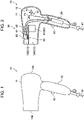
Fig. 1 is a side view of a hair care device according to an exemplary embodiment. -
Fig. 2 is a cross-sectional view of the hair care device inFig. 1 . -
Fig. 3 is a block diagram illustrating an electrical connection of the hair care device inFig. 1 . -
Fig. 4 is a flowchart illustrating an example of first control executed by a controller in a first exemplary embodiment. -
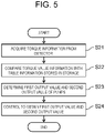
Fig. 5 is a flowchart illustrating an example of second control executed by a controller in a second exemplary embodiment. - (One example of modes that a hair care device can take)
- A hair care device according to the present disclosure is a hair care device including a tank that stores a liquid, a pump that outputs the liquid stored in the tank, and a controller that controls an output of the pump, the hair care device further including a detector that detects swing of the hair care device, in which the controller adjusts the output of the pump based on a detection value of the detector.
- According to the hair care device, because the output of the pump is controlled based on the detection value, the cosmetic component can be suitably sprayed.
- According to an example of the hair care device, the detector detects an angular velocity of the hair care device.
- According to the hair care device, the output of the pump can be controlled using the angular velocity.
- According to an example of the hair care device, the controller decreases the output of the pump as the angular velocity of the hair care device increases.
- According to the hair care device, because the output of the pump decreases as a value of the angular velocity increases, the liquid can be appropriately output.
- According to an example of the hair care device, the hair care device further includes an air blower that outputs gas and includes a motor and a fan, in which the controller adjusts an output of the motor based on the detection value of the detector.
- According to the hair care device, because the output of the motor is controlled based on the detection value, the control can be suitably executed.
- According to an example of the hair care device, the detector detects the angular velocity of the hair care device, and the controller increases the output of the motor as the angular velocity of the hair care device increases.
- According to the hair care device, an amount of air blow is increased when the angular velocity is large. Therefore, usability is improved.
- Hereinafter,
hair care device 10 of a first exemplary embodiment is described with reference toFigs. 1 to 3 .Hair care device 10 supplies at least one of a cosmetic component and air to the hair or the like of a user.Hair care device 10 is, for example, a dryer.Hair care device 10 includeshousing 11 that constitutes the appearance ofhair care device 10 and houses at least one of the other elements that constitutehair care device 10, andgrip 12 that is gripped by the user in use.Housing 11 andgrip 12 are preferably connected to each other by a connector configured to be able to change a position ofhousing 11 with respect togrip 12.Housing 11 andgrip 12 are made of any material having excellent heat resistance. In one example, thematerial constituting housing 11 andgrip 12 is polycarbonate.Housing 11 includessuction port 11A through which the external air flows in anddischarge port 11B through which the cosmetic component or the air is discharged to the outside.Suction port 11A preferably includes a filter that prevents dust or the like in the outside air from enteringhousing 11.Suction port 11A anddischarge port 11B each have, for example, an elliptical shape. -
Housing 11 includesflow path 13 in which a fluid flow is formed.Flow path 13 connectssuction port 11A anddischarge port 11B.Flow path 13 includesfirst flow path 13A through which mainly gas passes andsecond flow path 13B through which mainly cosmetic components pass. In one example, the length of each offirst flow path 13A andsecond flow path 13B is half the length of the entire length offlow path 13. -
Hair care device 10 further includescontroller 20,storage 30,operation unit 40,detector 50,power supply unit 60,air blower 70,heating unit 80, andmist generator 90. At least one ofcontroller 20,storage 30,operation unit 40,detector 50,power supply unit 60,air blower 70,heating unit 80, andmist generator 90 is held insidehousing 11. -
Controller 20 is constituted of an arithmetic processing unit that executes a control program. The arithmetic processing unit is constituted of, for example, at least one or both of a central processing unit (CPU) and a micro processing unit (MPU).Controller 20 is configured to be able to communicate withstorage 30,operation unit 40,detector 50,air blower 70,heating unit 80, andmist generator 90 in a wireless or wired manner.Controller 20 starts control when, for example, power is supplied frompower supply unit 60 and an operation signal is input fromoperation unit 40. Preferably,controller 20 is provided at a position away fromheating unit 80 as a heat generation source. In one example,controller 20 is provided at a location corresponding togrip 12. -
Storage 30 stores program information and table information for executing various controls executed bycontroller 20. The table information is information in which a detection value detected bydetector 50 is associated with appropriate amounts of output ofair blower 70 andmist generator 90.Storage 30 includes, for example, a non-volatile memory and a volatile memory.Storage 30 is provided in the same control circuit as, for example,controller 20. -
Operation unit 40 outputs an operation signal by, for example, an operation from the user to controller 20. The operation signal includes a signal for switching on and off ofcontroller 20 or a signal for changing the output of at least one ofair blower 70,heating unit 80, andmist generator 90 bycontroller 20. A part ofoperation unit 40 is configured to protrude toward the outside ofhousing 11 to allow the user to operate easily.Operation unit 40 is constituted of, for example, a button, a switch, and a dial.Operation unit 40 may be constituted of a touch panel.Operation unit 40 is mounted on, for example,grip 12. -
Detector 50 detects various pieces of information onhair care device 10. The detection value detected bydetector 50 is output tocontroller 20. In a first example,detector 50 is constituted of an acceleration sensor or a gyro sensor, and detects movement ofhair care device 10 in three axial directions. Specifically,detector 50 detects acceleration or angular velocity. In the case of the first example,detector 50 is preferably disposed insecond flow path 13B. In a second example,detector 50 detects torque of motors provided inair blower 70 andmist generator 90. Specifically,detector 50 is constituted of a torque sensor. Specifically,detector 50 may be configured to detect counter electromotive force. In one example,detector 50 is a microcomputer that controls a motor.Controller 20 calculates the rotation speed and the load torque of the motor from the counter electromotive force. In a third example,detector 50 detects the number of times used and a usage time period ofhair care device 10.Detector 50 includes a configuration of at least one of the first example and the second example. More preferably,detector 50 includes all the configurations ofdetector 50 from the first to third examples. -
Power supply unit 60 supplies power tocontroller 20,storage 30,operation unit 40,detector 50,air blower 70,heating unit 80, andmist generator 90. In the illustrated example,power supply unit 60 is an external power supply such as a commercial power supply.Power supply unit 60 may have a configuration of a secondary battery provided insidehousing 11. Whenpower supply unit 60 is the external power supply,hair care device 10 andpower supply unit 60 are connected bypower line 61. -
Air blower 70 forms a flow that sucks the air fromsuction port 11A and discharges the air fromdischarge port 11B.Air blower 70 includesmotor 71 andfan 72. Whenmotor 71 is driven to rotatefan 72, an air flow is generated inflow path 13.Motor 71 is controlled bycontroller 20.Air blower 70 is located upstream offirst flow path 13A andsecond flow path 13B inflow path 13, and supplies the air to bothfirst flow path 13A andsecond flow path 13B. -
Heating unit 80 heats the air inhousing 11 to produce hot air. The hot air is, for example, the air within a range of 100°C to 120°C inclusive.Heating unit 80 includesheater 81. An example ofheater 81 includes a positive temperature coefficient (PTC) heater or an infrared heater.Heating unit 80 is provided, for example, infirst flow path 13A.Controller 20 controls the output ofheater 81. -
Mist generator 90 forms the cosmetic component in a mist form. The cosmetic component is a liquid or a component contained in a liquid.Mist generator 90 includespump 91,tank 92, andnozzle 93.Pump 91 is a liquid pump that supplies the cosmetic component stored intank 92 tonozzle 93 by driving a motor (not shown). The liquid pump is, for example, a gear pump.Tank 92 stores the liquid containing the cosmetic component in the inside ofhair care device 10.Tank 92 is made of any material suitable for holding the liquid containing the cosmetic component. Examples include at least one of polyethylene, polypropylene, polyvinylidene chloride, nylon, polyethylene terephthalate, an ethylene vinyl alcohol copolymer, polyvinyl alcohol, and aluminum.Nozzle 93 forms the cosmetic component, which is a liquid, in a mist form.Nozzle 93 is made of resin or metal.Nozzle 93 includes a plurality of minute holes. When the cosmetic component of the liquid supplied bypump 91 passes through the minute holes, the cosmetic component is generated in a mist form. Alternatively, the cosmetic component and the gas are mixed insidenozzle 93 to generate the cosmetic component in a mist form by shearing force. In this case, pump 91 further includes a gas pump. The gas pump is, for example, a diaphragm pump. - The cosmetic component contains at least one of: amino acids such as glycine, alanine, valine, leucine, isoleucine, phenylalanine, proline, hydroxyproline, threonine, serine, tyrosine, methionine, tryptophan, cystine, cysteic acid, arginine, histidine, lysine, hydroxylysine, and glutamic acid; higher fatty acids such as capric acid, lauric acid, myristic acid, palmitic acid, stearic acid, behenic acid, oleic acid, coconut oil fatty acid, isostearic acid, isopalmitic acid, and α-linolenic acid; hydrocarbon oils such as liquid paraffin, liquid isoparaffin, vaseline, squalene, and squalane; natural oils such as camellia oil, macadamia oil, corn oil, olive oil, avocado oil, castor oil, safflower oil, jojoba oil, sunflower oil, rapeseed oil, sesame oil, soybean oil, and meadow foam oil; organic acids such as malic acid, tannic acid, citric acid; lipids such as cholesterol, ceramide 1, ceramide 2, ceramide 3, ceramide 1A, ceramide 611, 18-methyleicosanoic acid, cholesterol sulfate, triglyceride, and lysolecithin; higher alcohols such as stearyl alcohol and cetyl alcohol; esters such as beeswax, candelilla wax, carnarba wax, isopropyl palmitate, myristyl lactate, 2-ethylhexyl stearate, wax esters, isopropyl myristate, myristyl myristate, octyl palmitate, stearyl stearate, isocetyl stearate, isononyl isononanoate, isotridecyl isononanoate, hydrogenated castor oil stearate, hydroxystearate hydrogenated castor oil, glyceryl tri(2-ethylhexanoate), pentaerythritol tetra(2-ethylhexanoate), neopentyl glycol dicaprate, diglyceryl diisostearate, dipentaerythritol, and esters with mixed fatty acids such as hydroxystearic acid/stearic acid/rosin acid; silicones such as dimethylpolysiloxane, amino-modified silicone, polyether modified, and cationized silicone; antioxidants such as polyphenols, vitamins and fullerenes; polysaccharides such as D-galactose, D-glucuronic acid, L-fucose, D-mannose, chitosan, and cationized polysaccharides; humectants such as glycerin, water, xanthan gum, panthenol, sucrose, glucose, fructose, sorbitol, mannitol, xylitol, maltitol, diglycerin, triglycerin, propylene glycol, dipropylene glycol, polypropylene glycol, triethylene glycol, tetraethylene glycol, polyethylene glycol, 1,2-butylene glycol, 1,3-butylene glycol, 1,2-pentanediol, hexylene glycol, erythritol, polyoxyethylene methyl glucoside, and polyvinyl alcohol; sphingosines such as dihydrosphingosine, phytosphingosine, and hydroxy caproyl phytosphingosine; peptides such as collagen PPT, keratin PPT, silk PPT, pearl PPT, milk PPT, soybean PPT, cationized PPT derivatives of the above PPT, acylated PPT derivatives, silylated PPT derivatives, and ethyl esterified PPT derivatives; proteins such as sesame protein, protein obtained from seeds of leguminous plants, rice protein, protein obtained from shells having pearl layers or pearls, and protein obtained from silk; extracts such as ginseng extract, rice germ extract, fucales extract, camellia extract, aloe extract; shell ginger extract, and chlorella extract; metals such as zinc, magnesium, and calcium; polymer compounds such as cationized cellulose, hydroxylated cellulose, highly polymerized polyethylene oxide, and cationized synthetic polymer; anti-dandruff agents such as zinc pyrithione and benzalkonium chloride; and antibacterial agents such as dipotassium glycyrrhizinate.
- First control executed by
controller 20 is described with reference toFig. 4 . - The first control is control executed by
controller 20 at predetermined intervals when the user useshair care device 10.Detector 50 includes a configuration ofdetector 50 of at least the first example. - In step S11,
controller 20 acquires angular velocity information including the angular velocity ofhair care device 10 fromdetector 50. In step S12,controller 20 compares the angular velocity information with table information stored instorage 30. The table information stores outputs ofair blower 70 andmist generator 90 appropriate for the angular velocity ofhair care device 10 in association with experimentally obtained results. Specifically, when the angular velocity is large,controller 20 reduces the output of the motor ofmist generator 90 and supply capability ofpump 91, and controls an amount of mist output fromsecond flow path 13B to be small. When the angular velocity is large,controller 20 increases the output ofmotor 71 ofair blower 70 to increase the air volume output fromfirst flow path 13A. - In step S13,
controller 20 determines a first output value ofpump 91 ofmist generator 90 and a second output value ofmotor 71 ofair blower 70 from the table information. In step S14,controller 20 controls to make the output ofpump 91 ofmist generator 90 become the first output value and the output ofmotor 71 ofair blower 70 become the second output value. After completion of step S14,controller 20 ends the control. - An operation of
hair care device 10 of the first exemplary embodiment is described. - When the user operates
operation unit 40, power is supplied tohair care device 10. The user performs hair care by directingdischarge port 11B ofhair care device 10 toward the hair.Controller 20 controls the output ofpump 91 ofmist generator 90 and the output ofmotor 71 ofair blower 70 in accordance with the operation ofhair care device 10 by the user. -
Hair care device 10 of a second exemplary embodiment is different fromhair care device 10 of the first exemplary embodiment in thatdetector 50 includes the configuration of the second example, andcontroller 20 performs control based on a detection value ofdetector 50 of the second example. A part or all of the description of the configuration similar to that ofhair care device 10 of the first exemplary embodiment may be omitted. -
Controller 20 executes control based on a value of a torque sensor configured asdetector 50. The torque sensor detects torque of a motor provided inhair care device 10. In one example,detector 50 detects the torque of amotor constituting pump 91 ofmist generator 90.Pump 91 includes liquid feed pump 910 that supplies the cosmetic component fromtank 92 tonozzle 93 and air blower pump 920 that supplies gas tonozzle 93. Liquid feed pump 910 is, for example, a gear pump. Air blower pump 920 is, for example, a diaphragm pump. - Second control executed by
controller 20 is described with reference toFig. 5 . - The second control is control for determining a first output value of liquid feed pump 910 and a second output value of air blower pump 920
constituting pump 91 ofmist generator 90 during a predetermined period from the start of use ofhair care device 10.Controller 20 executes the process of step S21 whenpump 91 operates. - In step S21,
controller 20 acquires torque value information fromdetector 50. Specifically, the torque value information of the motor of liquid feed pump 910 is detected. In the case where the torque value information is acquired over time and the torque exceeds the first maximum value,controller 20 proceeds to the process of step S22. - In step S22,
controller 20 compares the torque value information with table information stored instorage 30. The table information is information in which the torque value information experimentally obtained in advance is associated with the type of the cosmetic component. Specifically, the higher the viscosity of the cosmetic component, the higher the torque value, and the lower the viscosity of the cosmetic component, the lower the torque value.Controller 20 estimates the cosmetic component stored intank 92 ofhair care device 10 from the table information, and determines the type of the cosmetic component. - In step S23,
controller 20 determines the first output value and the second output value ofpump 91 based on the determined type of the cosmetic component. Specifically,controller 20 determines the first output value that is the torque of the motor of liquid feed pump 910 and the second output value that is the torque of the motor of air blower pump 920. In step S24,controller 20 controls to make the outputs of the motor ofpump 91 ofmist generator 90 become the first output value and the second output value. After completion of step S24,controller 20 ends the control. - An operation of
hair care device 10 of the second exemplary embodiment is described - When the user operates
operation unit 40, power is supplied tohair care device 10. The user performs hair care by directingdischarge port 11B ofhair care device 10 toward the hair.Controller 20 determines the type of the cosmetic component, and controls the output ofpump 91 ofmist generator 90 according to the type of the cosmetic component used by the user. -
Hair care device 10 according to a third exemplary embodiment is different fromhair care device 10 according to the second exemplary embodiment in that table information stored instorage 30 does not include types of cosmetic components. A part or all of the description of the configuration similar to that ofhair care device 10 of the first exemplary embodiment and the second exemplary embodiment may be omitted. -
Controller 20 detects torque of a motor of liquid feed pump 910 and torque of a motor of air blower pump 920 fromdetector 50 of the second example, and executes third control for determining a first output value and a second output value ofpump 91 based on the detected torque value information. - The third control is described.
Controller 20 acquires the torque and the rotation speed of the motor of liquid feed pump 910 fromdetector 50 simultaneously with the start of liquid feed pump 910.Controller 20 increases the output of liquid feed pump 910 until the rotation speed of liquid feeding pump 910 reaches a predetermined rotation speed. An optional rotation speed is set as the predetermined rotation speed. For example, the rotation speed is set to the rotation speed in the case of supplying pure water tonozzle 93 by liquid feed pump 910. -
Controller 20 starts the motor of air blower pump 920 and estimates the load torque of the motor of air blower pump 920. The load torque is estimated based on the counter electromotive force detected bydetector 50.Controller 20 sets an input voltage of the motor of air blower pump 920 in which a fluctuation range of the load torque is less than or equal to a certain value. When the size of the mist of the cosmetic component is not appropriate, the fluctuation range of the load torque increases. Because the rotation speed of the motor of liquid feed pump 910 increases by the output of air blower pump 920,controller 20 decreases the output of liquid feed pump 910 until the rotation speed of the motor of liquid feed pump 910 reaches a predetermined rotation speed.Controller 20 respectively drives the motor of liquid feed pump 910 and the motor of air blower pump 920 at suitable rotation speeds.Controller 20 repeatedly executes the third control whilehair care device 10 is in operation. - According to
hair care device 10 of the third exemplary embodiment, the following effect can be obtained. -
Controller 20 can execute appropriate output based on the detection values of the motors of liquid feed pump 910 and air blower pump 920. Therefore, even when the type of cosmetic component cannot be identified, the output ofpump 91 can be suitably controlled. - The descriptions relating to the exemplary embodiments are merely examples of modes that the hair care device of the present invention can take, and do not intend to limit such modes. The present invention can include, in addition to the exemplary embodiments, for example, following modifications of the exemplary embodiments, and any configurations acquired by combining at least two modifications which do not contradict with each other.
-
Hair care device 10 according to the first to third exemplary embodiments may further include a configuration of a notification unit that notifies of various kinds of information. The notification unit notifies of, for example, information detected bydetector 50. The notification unit is constituted of, for example, a display. - In
hair care device 10 according to the second exemplary embodiment,controller 20 may further controlheater 81. In one example,controller 20 changes the output ofheater 81 according to the type of the cosmetic component. The table information further includes information for associating the type of cosmetic component with an appropriate blowing temperature. - A hair care device according to the present disclosure can be used for commercial and home hair care devices that are used for hair care.
-
- 10
- hair care device
- 20
- controller
- 50
- detector
- 70
- air blower
- 71
- motor
- 72
- fan
- 90
- mist generator
- 91
- pump
- 910
- liquid feed pump
- 920
- air blower pump
- 92
- tank
Claims (5)
- A hair care device comprising:a tank that stores a liquid;a pump that outputs the liquid stored in the tank;a controller that controls an output of the pump; anda detector that detects swing of the hair care device,wherein the controller adjusts the output of the pump based on a detection value of the detector.
- The hair care device according to Claim 1, wherein the detector detects an angular velocity of the hair care device.
- The hair care device according to Claim 2, wherein the controller decreases the output of the pump as the angular velocity of the hair care device increases.
- The hair care device according to any one of Claims 1 to 3, further comprising an air blower that outputs gas and includes a motor and a fan, wherein the controller adjusts an output of the motor based on the detection value of the detector.
- The hair care device according to Claim 4, whereinthe detector detects the angular velocity of the hair care device, andthe controller increases the output of the motor as the angular velocity of the hair care device increases.
Applications Claiming Priority (2)
| Application Number | Priority Date | Filing Date | Title |
|---|---|---|---|
| JP2020028769A JP7555034B2 (en) | 2020-02-21 | 2020-02-21 | Hair Care Device |
| PCT/JP2021/003193 WO2021166593A1 (en) | 2020-02-21 | 2021-01-29 | Hair care device |
Publications (3)
| Publication Number | Publication Date |
|---|---|
| EP4108127A1 true EP4108127A1 (en) | 2022-12-28 |
| EP4108127A4 EP4108127A4 (en) | 2023-07-19 |
| EP4108127B1 EP4108127B1 (en) | 2026-03-11 |
Family
ID=77391329
Family Applications (1)
| Application Number | Title | Priority Date | Filing Date |
|---|---|---|---|
| EP21756934.2A Active EP4108127B1 (en) | 2020-02-21 | 2021-01-29 | Hair care device |
Country Status (5)
| Country | Link |
|---|---|
| US (1) | US12389995B2 (en) |
| EP (1) | EP4108127B1 (en) |
| JP (1) | JP7555034B2 (en) |
| CN (1) | CN115023162B (en) |
| WO (1) | WO2021166593A1 (en) |
Families Citing this family (1)
| Publication number | Priority date | Publication date | Assignee | Title |
|---|---|---|---|---|
| JP7454793B2 (en) * | 2020-02-21 | 2024-03-25 | パナソニックIpマネジメント株式会社 | hair care equipment |
Family Cites Families (23)
| Publication number | Priority date | Publication date | Assignee | Title |
|---|---|---|---|---|
| US2663090A (en) * | 1951-02-20 | 1953-12-22 | Lillian R Flaxman | Hair drying hood construction |
| DE3274948D1 (en) * | 1981-08-14 | 1987-02-12 | Edward Rex Raccah | Hair drying apparatus |
| JP3120866B2 (en) * | 1991-05-23 | 2000-12-25 | 松下電工株式会社 | Mist hair dryer |
| JPH05228015A (en) * | 1992-02-20 | 1993-09-07 | Sanyo Electric Co Ltd | Hair drier |
| US5608975A (en) * | 1996-05-29 | 1997-03-11 | Hsu; Jong-Yes | Collapsible and portable hair dryer with combustion heat supply system |
| US6449870B1 (en) * | 2000-09-15 | 2002-09-17 | Louis Perez | Portable hair dryer |
| AR047033A1 (en) * | 2004-11-05 | 2006-01-04 | Duna Entpr Sa | HAIR DRYER PROGRAMMABLE MANUAL TYPE WITH MULTIPLE FUNCTIONS |
| ES2795355T3 (en) * | 2009-07-10 | 2020-11-23 | Braun Gmbh | Automated hair care process |
| JP5701895B2 (en) * | 2009-12-06 | 2015-04-15 | シネロン メディカル リミテッド | Method and apparatus for personal skin treatment |
| CN103140147A (en) * | 2010-09-24 | 2013-06-05 | 松下电器产业株式会社 | Method for controlling automatic head care system, method for controlling automatic hair washing system, and automatic head care system |
| DE102011007420A1 (en) * | 2011-04-14 | 2012-10-18 | BSH Bosch und Siemens Hausgeräte GmbH | Hand-held dryer |
| EP2777731B1 (en) | 2011-11-10 | 2017-01-11 | Panasonic Healthcare Holdings Co., Ltd. | Pharmaceutical injection device |
| EP2833988A4 (en) * | 2012-04-02 | 2016-04-13 | Air Sanz Holdings Pty Ltd | Air purifying apparatus, method&system |
| CN205624974U (en) * | 2016-04-07 | 2016-10-12 | 谭新亮 | Marcel waver |
| WO2018009859A1 (en) * | 2016-07-08 | 2018-01-11 | T3 Micro, Inc. | Motion sensing hair dryer |
| US10909881B2 (en) * | 2016-09-13 | 2021-02-02 | L'oreal | Systems, devices, and methods including connected styling tools |
| JP6681575B2 (en) | 2017-05-24 | 2020-04-15 | パナソニックIpマネジメント株式会社 | Liquid spraying device and portable beauty equipment |
| JP6981106B2 (en) | 2017-08-29 | 2021-12-15 | 株式会社リコー | Image pickup device, image display system, operation method, program |
| US10918184B1 (en) * | 2020-02-27 | 2021-02-16 | Tech 4 Hair, Llc | Smart nozzle for hair dryer |
| US11602208B2 (en) * | 2020-03-18 | 2023-03-14 | Airgle Corporation | Hair dryer |
| WO2022008408A1 (en) * | 2020-07-07 | 2022-01-13 | Koninklijke Philips N.V. | Hair dryer |
| JP7531160B2 (en) * | 2021-02-05 | 2024-08-09 | パナソニックIpマネジメント株式会社 | Hair Care Device |
| US20250107607A1 (en) * | 2023-09-28 | 2025-04-03 | L'oreal | Camera Sensor |
-
2020
- 2020-02-21 JP JP2020028769A patent/JP7555034B2/en active Active
-
2021
- 2021-01-29 WO PCT/JP2021/003193 patent/WO2021166593A1/en not_active Ceased
- 2021-01-29 CN CN202180008808.2A patent/CN115023162B/en active Active
- 2021-01-29 EP EP21756934.2A patent/EP4108127B1/en active Active
- 2021-01-29 US US17/784,023 patent/US12389995B2/en active Active
Also Published As
| Publication number | Publication date |
|---|---|
| EP4108127A4 (en) | 2023-07-19 |
| US20230009980A1 (en) | 2023-01-12 |
| EP4108127B1 (en) | 2026-03-11 |
| US12389995B2 (en) | 2025-08-19 |
| CN115023162A (en) | 2022-09-06 |
| JP2021132686A (en) | 2021-09-13 |
| JP7555034B2 (en) | 2024-09-24 |
| CN115023162B (en) | 2024-10-22 |
| WO2021166593A1 (en) | 2021-08-26 |
Similar Documents
| Publication | Publication Date | Title |
|---|---|---|
| EP4108126B1 (en) | Cosmetic component spraying device | |
| EP4108129B1 (en) | Haircare device | |
| US12389995B2 (en) | Hair care device | |
| JP2009190789A (en) | Device for spraying a cosmetic composition | |
| TW201936159A (en) | Composition for forming coating film | |
| CN103140204B (en) | Pressurized mist bath system | |
| EP4108128B1 (en) | Beauty component nebulizer | |
| US9585819B2 (en) | Moisturizing apparatus and electrical equipment including the same, and moisturizing method | |
| EP4108125B1 (en) | Cosmetic ingredient spraying device | |
| CN202955816U (en) | Humidification oxygen adding device used for smartly controlling facial portion to moisten | |
| EP4371549A1 (en) | Cosmetic material and hairdressing appliance | |
| CN215082021U (en) | Traditional Chinese medicine fumigation apparatus nozzle and Chinese medicine fumigation apparatus that can be dried and the air output can be adjusted | |
| JP2022039741A (en) | Electrospinning composition for deodorization | |
| JP7555762B2 (en) | Hair Care Equipment | |
| JP2013142332A (en) | Air blowing device | |
| WO2023145306A1 (en) | Hair and/or skin composition, method for treating hair and/or skin, and device for hair and/or skin | |
| JP2023111819A (en) | Hair and/or skin composition, hair and/or skin treatment method and hair and/or skin device | |
| CN118750261A (en) | Head/face care device and air blower including the head/face care device | |
| JP2010172660A (en) | Mist generator | |
| CN109611364A (en) | A kind of bladeless fan |
Legal Events
| Date | Code | Title | Description |
|---|---|---|---|
| STAA | Information on the status of an ep patent application or granted ep patent |
Free format text: STATUS: THE INTERNATIONAL PUBLICATION HAS BEEN MADE |
|
| PUAI | Public reference made under article 153(3) epc to a published international application that has entered the european phase |
Free format text: ORIGINAL CODE: 0009012 |
|
| STAA | Information on the status of an ep patent application or granted ep patent |
Free format text: STATUS: REQUEST FOR EXAMINATION WAS MADE |
|
| 17P | Request for examination filed |
Effective date: 20220719 |
|
| AK | Designated contracting states |
Kind code of ref document: A1 Designated state(s): AL AT BE BG CH CY CZ DE DK EE ES FI FR GB GR HR HU IE IS IT LI LT LU LV MC MK MT NL NO PL PT RO RS SE SI SK SM TR |
|
| DAV | Request for validation of the european patent (deleted) | ||
| DAX | Request for extension of the european patent (deleted) | ||
| A4 | Supplementary search report drawn up and despatched |
Effective date: 20230619 |
|
| RIC1 | Information provided on ipc code assigned before grant |
Ipc: A45D 1/00 20060101ALN20230613BHEP Ipc: B05B 12/12 20060101ALI20230613BHEP Ipc: B05B 12/08 20060101ALI20230613BHEP Ipc: B05B 7/24 20060101ALI20230613BHEP Ipc: B05B 7/00 20060101ALI20230613BHEP Ipc: A45D 34/04 20060101ALI20230613BHEP Ipc: B05B 7/04 20060101ALI20230613BHEP Ipc: B05B 12/00 20180101ALI20230613BHEP Ipc: A45D 20/12 20060101ALI20230613BHEP Ipc: A45D 20/10 20060101AFI20230613BHEP |
|
| GRAP | Despatch of communication of intention to grant a patent |
Free format text: ORIGINAL CODE: EPIDOSNIGR1 |
|
| STAA | Information on the status of an ep patent application or granted ep patent |
Free format text: STATUS: GRANT OF PATENT IS INTENDED |
|
| RIC1 | Information provided on ipc code assigned before grant |
Ipc: A45D 20/10 20060101AFI20250929BHEP Ipc: A45D 20/12 20060101ALI20250929BHEP Ipc: B05B 12/00 20180101ALI20250929BHEP Ipc: B05B 7/04 20060101ALI20250929BHEP Ipc: A45D 34/04 20060101ALI20250929BHEP Ipc: B05B 7/00 20060101ALI20250929BHEP Ipc: B05B 7/24 20060101ALI20250929BHEP Ipc: B05B 12/08 20060101ALI20250929BHEP Ipc: B05B 12/12 20060101ALI20250929BHEP Ipc: A45D 1/00 20060101ALN20250929BHEP |
|
| INTG | Intention to grant announced |
Effective date: 20251010 |
|
| RIN1 | Information on inventor provided before grant (corrected) |
Inventor name: OIKAZE, HIROTOSHI Inventor name: CHIKAZAWA, YUKI Inventor name: KINOSHITA, MASATO Inventor name: INOUE, HIROYUKI Inventor name: HANATO, YUMI |
|
| GRAS | Grant fee paid |
Free format text: ORIGINAL CODE: EPIDOSNIGR3 |
|
| GRAA | (expected) grant |
Free format text: ORIGINAL CODE: 0009210 |
|
| STAA | Information on the status of an ep patent application or granted ep patent |
Free format text: STATUS: THE PATENT HAS BEEN GRANTED |
|
| AK | Designated contracting states |
Kind code of ref document: B1 Designated state(s): AL AT BE BG CH CY CZ DE DK EE ES FI FR GB GR HR HU IE IS IT LI LT LU LV MC MK MT NL NO PL PT RO RS SE SI SK SM TR |
|
| REG | Reference to a national code |
Ref country code: CH Ref legal event code: F10 Free format text: ST27 STATUS EVENT CODE: U-0-0-F10-F00 (AS PROVIDED BY THE NATIONAL OFFICE) Effective date: 20260311 Ref country code: GB Ref legal event code: FG4D |
|
| REG | Reference to a national code |
Ref country code: DE Ref legal event code: R096 Ref document number: 602021049757 Country of ref document: DE |
|
| REG | Reference to a national code |
Ref country code: IE Ref legal event code: FG4D |