EP4108115A1 - Shock absorber, shoe sole, and shoe - Google Patents
Shock absorber, shoe sole, and shoe Download PDFInfo
- Publication number
- EP4108115A1 EP4108115A1 EP22179516.4A EP22179516A EP4108115A1 EP 4108115 A1 EP4108115 A1 EP 4108115A1 EP 22179516 A EP22179516 A EP 22179516A EP 4108115 A1 EP4108115 A1 EP 4108115A1
- Authority
- EP
- European Patent Office
- Prior art keywords
- shape
- shock absorber
- dimensional structure
- structure body
- shoe sole
- Prior art date
- Legal status (The legal status is an assumption and is not a legal conclusion. Google has not performed a legal analysis and makes no representation as to the accuracy of the status listed.)
- Granted
Links
- 230000035939 shock Effects 0.000 title claims abstract description 300
- 239000006096 absorbing agent Substances 0.000 title claims abstract description 215
- 230000008859 change Effects 0.000 claims abstract description 19
- 230000003014 reinforcing effect Effects 0.000 claims description 13
- 239000011159 matrix material Substances 0.000 claims description 4
- 210000002683 foot Anatomy 0.000 description 28
- 229920000642 polymer Polymers 0.000 description 25
- 238000004088 simulation Methods 0.000 description 23
- 229920001577 copolymer Polymers 0.000 description 22
- 230000000052 comparative effect Effects 0.000 description 19
- 230000004048 modification Effects 0.000 description 17
- 238000012986 modification Methods 0.000 description 17
- 229920005989 resin Polymers 0.000 description 16
- 239000011347 resin Substances 0.000 description 15
- 239000012790 adhesive layer Substances 0.000 description 11
- 229920001971 elastomer Polymers 0.000 description 11
- PPBRXRYQALVLMV-UHFFFAOYSA-N Styrene Chemical compound C=CC1=CC=CC=C1 PPBRXRYQALVLMV-UHFFFAOYSA-N 0.000 description 10
- 239000000463 material Substances 0.000 description 9
- 210000000452 mid-foot Anatomy 0.000 description 9
- 229920000058 polyacrylate Polymers 0.000 description 9
- JOYRKODLDBILNP-UHFFFAOYSA-N Ethyl urethane Chemical compound CCOC(N)=O JOYRKODLDBILNP-UHFFFAOYSA-N 0.000 description 8
- -1 TPAE) Polymers 0.000 description 7
- 230000000694 effects Effects 0.000 description 6
- 239000000806 elastomer Substances 0.000 description 6
- 239000005038 ethylene vinyl acetate Substances 0.000 description 6
- 210000004744 fore-foot Anatomy 0.000 description 6
- 238000004519 manufacturing process Methods 0.000 description 6
- 125000005395 methacrylic acid group Chemical group 0.000 description 6
- 229920001200 poly(ethylene-vinyl acetate) Polymers 0.000 description 6
- 229920000728 polyester Polymers 0.000 description 6
- 229920002725 thermoplastic elastomer Polymers 0.000 description 6
- 238000006073 displacement reaction Methods 0.000 description 5
- 230000002093 peripheral effect Effects 0.000 description 5
- 239000005060 rubber Substances 0.000 description 5
- 238000012795 verification Methods 0.000 description 5
- 239000004433 Thermoplastic polyurethane Substances 0.000 description 4
- 150000001408 amides Chemical class 0.000 description 4
- 150000002148 esters Chemical class 0.000 description 4
- 229920002803 thermoplastic polyurethane Polymers 0.000 description 4
- 239000005062 Polybutadiene Substances 0.000 description 3
- 239000004721 Polyphenylene oxide Substances 0.000 description 3
- 239000000654 additive Substances 0.000 description 3
- 230000000996 additive effect Effects 0.000 description 3
- 238000000034 method Methods 0.000 description 3
- 230000000737 periodic effect Effects 0.000 description 3
- 229920002857 polybutadiene Polymers 0.000 description 3
- 229920000570 polyether Polymers 0.000 description 3
- 229920000468 styrene butadiene styrene block copolymer Polymers 0.000 description 3
- 239000004593 Epoxy Substances 0.000 description 2
- 244000043261 Hevea brasiliensis Species 0.000 description 2
- 229920000459 Nitrile rubber Polymers 0.000 description 2
- XECAHXYUAAWDEL-UHFFFAOYSA-N acrylonitrile butadiene styrene Chemical compound C=CC=C.C=CC#N.C=CC1=CC=CC=C1 XECAHXYUAAWDEL-UHFFFAOYSA-N 0.000 description 2
- 239000004676 acrylonitrile butadiene styrene Substances 0.000 description 2
- 229920000122 acrylonitrile butadiene styrene Polymers 0.000 description 2
- 229920005549 butyl rubber Polymers 0.000 description 2
- 230000007423 decrease Effects 0.000 description 2
- 150000001993 dienes Chemical class 0.000 description 2
- 239000013013 elastic material Substances 0.000 description 2
- 239000004744 fabric Substances 0.000 description 2
- 239000006261 foam material Substances 0.000 description 2
- 229920001903 high density polyethylene Polymers 0.000 description 2
- 239000004700 high-density polyethylene Substances 0.000 description 2
- 230000001771 impaired effect Effects 0.000 description 2
- 229920003049 isoprene rubber Polymers 0.000 description 2
- 239000000203 mixture Substances 0.000 description 2
- 229920003052 natural elastomer Polymers 0.000 description 2
- 229920001194 natural rubber Polymers 0.000 description 2
- 229920001084 poly(chloroprene) Polymers 0.000 description 2
- 229920002647 polyamide Polymers 0.000 description 2
- 239000004417 polycarbonate Substances 0.000 description 2
- 229920000515 polycarbonate Polymers 0.000 description 2
- 229920005672 polyolefin resin Polymers 0.000 description 2
- 229920002635 polyurethane Polymers 0.000 description 2
- 239000004814 polyurethane Substances 0.000 description 2
- 230000008569 process Effects 0.000 description 2
- 230000008719 thickening Effects 0.000 description 2
- PKHKSCDFQWKYKA-UHFFFAOYSA-N C=CC1=CC=CC=C1.C=CC=C.C=CC1=CC=CC=C1.C=CC=C.C=CC1=CC=CC=C1 Chemical compound C=CC1=CC=CC=C1.C=CC=C.C=CC1=CC=CC=C1.C=CC=C.C=CC1=CC=CC=C1 PKHKSCDFQWKYKA-UHFFFAOYSA-N 0.000 description 1
- 229920010126 Linear Low Density Polyethylene (LLDPE) Polymers 0.000 description 1
- 229920000571 Nylon 11 Polymers 0.000 description 1
- 229920000299 Nylon 12 Polymers 0.000 description 1
- 229920002292 Nylon 6 Polymers 0.000 description 1
- 229920000305 Nylon 6,10 Polymers 0.000 description 1
- 229920002302 Nylon 6,6 Polymers 0.000 description 1
- 239000004698 Polyethylene Substances 0.000 description 1
- 239000004743 Polypropylene Substances 0.000 description 1
- 239000004793 Polystyrene Substances 0.000 description 1
- 238000005299 abrasion Methods 0.000 description 1
- 229920001893 acrylonitrile styrene Polymers 0.000 description 1
- 239000000853 adhesive Substances 0.000 description 1
- 230000001070 adhesive effect Effects 0.000 description 1
- 210000003423 ankle Anatomy 0.000 description 1
- BDGJRWFEEJVDBX-UHFFFAOYSA-N but-1-ene;4-methylpent-1-ene Chemical compound CCC=C.CC(C)CC=C BDGJRWFEEJVDBX-UHFFFAOYSA-N 0.000 description 1
- UREWAKSZTRITCZ-UHFFFAOYSA-N buta-1,3-diene;styrene Chemical compound C=CC=C.C=CC=C.C=CC1=CC=CC=C1.C=CC1=CC=CC=C1 UREWAKSZTRITCZ-UHFFFAOYSA-N 0.000 description 1
- FACXGONDLDSNOE-UHFFFAOYSA-N buta-1,3-diene;styrene Chemical compound C=CC=C.C=CC1=CC=CC=C1.C=CC1=CC=CC=C1 FACXGONDLDSNOE-UHFFFAOYSA-N 0.000 description 1
- QYMGIIIPAFAFRX-UHFFFAOYSA-N butyl prop-2-enoate;ethene Chemical compound C=C.CCCCOC(=O)C=C QYMGIIIPAFAFRX-UHFFFAOYSA-N 0.000 description 1
- 238000007599 discharging Methods 0.000 description 1
- 229920005648 ethylene methacrylic acid copolymer Polymers 0.000 description 1
- 229920006245 ethylene-butyl acrylate Polymers 0.000 description 1
- 229920006244 ethylene-ethyl acrylate Polymers 0.000 description 1
- 229920006225 ethylene-methyl acrylate Polymers 0.000 description 1
- 229920005680 ethylene-methyl methacrylate copolymer Polymers 0.000 description 1
- 239000002649 leather substitute Substances 0.000 description 1
- 229920003145 methacrylic acid copolymer Polymers 0.000 description 1
- 229940117841 methacrylic acid copolymer Drugs 0.000 description 1
- 239000004745 nonwoven fabric Substances 0.000 description 1
- 229920006285 olefinic elastomer Polymers 0.000 description 1
- 239000005022 packaging material Substances 0.000 description 1
- 229920003229 poly(methyl methacrylate) Polymers 0.000 description 1
- 229920001707 polybutylene terephthalate Polymers 0.000 description 1
- 229920000573 polyethylene Polymers 0.000 description 1
- 229920000139 polyethylene terephthalate Polymers 0.000 description 1
- 239000005020 polyethylene terephthalate Substances 0.000 description 1
- 239000004926 polymethyl methacrylate Substances 0.000 description 1
- 229920000098 polyolefin Polymers 0.000 description 1
- 229920001155 polypropylene Polymers 0.000 description 1
- 229920001296 polysiloxane Polymers 0.000 description 1
- 229920002223 polystyrene Polymers 0.000 description 1
- 239000004800 polyvinyl chloride Substances 0.000 description 1
- 229920000915 polyvinyl chloride Polymers 0.000 description 1
- SCUZVMOVTVSBLE-UHFFFAOYSA-N prop-2-enenitrile;styrene Chemical compound C=CC#N.C=CC1=CC=CC=C1 SCUZVMOVTVSBLE-UHFFFAOYSA-N 0.000 description 1
- 238000009958 sewing Methods 0.000 description 1
- 229920003048 styrene butadiene rubber Polymers 0.000 description 1
- 239000000057 synthetic resin Substances 0.000 description 1
- 238000003466 welding Methods 0.000 description 1
- 239000002759 woven fabric Substances 0.000 description 1
Images


Classifications
-
- A—HUMAN NECESSITIES
- A43—FOOTWEAR
- A43B—CHARACTERISTIC FEATURES OF FOOTWEAR; PARTS OF FOOTWEAR
- A43B1/00—Footwear characterised by the material
- A43B1/10—Footwear characterised by the material made of rubber
-
- A—HUMAN NECESSITIES
- A43—FOOTWEAR
- A43B—CHARACTERISTIC FEATURES OF FOOTWEAR; PARTS OF FOOTWEAR
- A43B13/00—Soles; Sole-and-heel integral units
- A43B13/02—Soles; Sole-and-heel integral units characterised by the material
- A43B13/12—Soles with several layers of different materials
- A43B13/125—Soles with several layers of different materials characterised by the midsole or middle layer
-
- A—HUMAN NECESSITIES
- A43—FOOTWEAR
- A43B—CHARACTERISTIC FEATURES OF FOOTWEAR; PARTS OF FOOTWEAR
- A43B13/00—Soles; Sole-and-heel integral units
- A43B13/14—Soles; Sole-and-heel integral units characterised by the constructive form
- A43B13/18—Resilient soles
- A43B13/181—Resiliency achieved by the structure of the sole
- A43B13/186—Differential cushioning region, e.g. cushioning located under the ball of the foot
-
- A—HUMAN NECESSITIES
- A43—FOOTWEAR
- A43B—CHARACTERISTIC FEATURES OF FOOTWEAR; PARTS OF FOOTWEAR
- A43B1/00—Footwear characterised by the material
- A43B1/0009—Footwear characterised by the material made at least partially of alveolar or honeycomb material
-
- A—HUMAN NECESSITIES
- A43—FOOTWEAR
- A43B—CHARACTERISTIC FEATURES OF FOOTWEAR; PARTS OF FOOTWEAR
- A43B13/00—Soles; Sole-and-heel integral units
- A43B13/02—Soles; Sole-and-heel integral units characterised by the material
- A43B13/04—Plastics, rubber or vulcanised fibre
-
- A—HUMAN NECESSITIES
- A43—FOOTWEAR
- A43B—CHARACTERISTIC FEATURES OF FOOTWEAR; PARTS OF FOOTWEAR
- A43B13/00—Soles; Sole-and-heel integral units
- A43B13/14—Soles; Sole-and-heel integral units characterised by the constructive form
- A43B13/18—Resilient soles
- A43B13/181—Resiliency achieved by the structure of the sole
-
- A—HUMAN NECESSITIES
- A43—FOOTWEAR
- A43B—CHARACTERISTIC FEATURES OF FOOTWEAR; PARTS OF FOOTWEAR
- A43B13/00—Soles; Sole-and-heel integral units
- A43B13/14—Soles; Sole-and-heel integral units characterised by the constructive form
- A43B13/18—Resilient soles
- A43B13/187—Resiliency achieved by the features of the material, e.g. foam, non liquid materials
-
- A—HUMAN NECESSITIES
- A43—FOOTWEAR
- A43B—CHARACTERISTIC FEATURES OF FOOTWEAR; PARTS OF FOOTWEAR
- A43B21/00—Heels; Top-pieces or top-lifts
- A43B21/24—Heels; Top-pieces or top-lifts characterised by the constructive form
- A43B21/26—Resilient heels
-
- A—HUMAN NECESSITIES
- A43—FOOTWEAR
- A43B—CHARACTERISTIC FEATURES OF FOOTWEAR; PARTS OF FOOTWEAR
- A43B3/00—Footwear characterised by the shape or the use
-
- F—MECHANICAL ENGINEERING; LIGHTING; HEATING; WEAPONS; BLASTING
- F16—ENGINEERING ELEMENTS AND UNITS; GENERAL MEASURES FOR PRODUCING AND MAINTAINING EFFECTIVE FUNCTIONING OF MACHINES OR INSTALLATIONS; THERMAL INSULATION IN GENERAL
- F16F—SPRINGS; SHOCK-ABSORBERS; MEANS FOR DAMPING VIBRATION
- F16F3/00—Spring units consisting of several springs, e.g. for obtaining a desired spring characteristic
- F16F3/08—Spring units consisting of several springs, e.g. for obtaining a desired spring characteristic with springs made of a material having high internal friction, e.g. rubber
- F16F3/087—Units comprising several springs made of plastics or the like material
- F16F3/0873—Units comprising several springs made of plastics or the like material of the same material or the material not being specified
- F16F3/0876—Units comprising several springs made of plastics or the like material of the same material or the material not being specified and of the same shape
-
- F—MECHANICAL ENGINEERING; LIGHTING; HEATING; WEAPONS; BLASTING
- F16—ENGINEERING ELEMENTS AND UNITS; GENERAL MEASURES FOR PRODUCING AND MAINTAINING EFFECTIVE FUNCTIONING OF MACHINES OR INSTALLATIONS; THERMAL INSULATION IN GENERAL
- F16F—SPRINGS; SHOCK-ABSORBERS; MEANS FOR DAMPING VIBRATION
- F16F7/00—Vibration-dampers; Shock-absorbers
- F16F7/12—Vibration-dampers; Shock-absorbers using plastic deformation of members
- F16F7/121—Vibration-dampers; Shock-absorbers using plastic deformation of members the members having a cellular, e.g. honeycomb, structure
Definitions
- the present invention relates to a shock absorber absorbing shock, a shoe sole including the shock absorber, and a shoe including the shoe sole.
- a shoe may have a shoe sole provided with a shock absorber in order to absorb shock caused upon landing.
- the shock absorber provided to the shoe sole is typically composed of a member made of resin or rubber.
- shoes having a shoe sole provided with a part having a lattice structure, a web structure or the like so that not only a material but also a structure provides an enhanced shock absorbing function.
- a shoe comprising a shoe sole provided with a part having a lattice structure is disclosed for example in U.S. Patent Publication No. 2018/0049514 .
- Japanese National Patent Publication No. 2017-527637 describes that a three-dimensional object which is manufactured in a three-dimensional additive manufacturing method can be manufactured by adding thickness to a geometrical surface structure, such as an internally hollowed polyhedron or a triply periodic minimal surface, and discloses that composing the three-dimensional object of an elastic material allows the object to be applied for example to a shoe sole.
- a property required for the shock absorber includes tending to gradually increase a load when the shock absorber is compressively deformed.
- the shock absorber has such the property, the shock absorber is stably displaced in a process of increasing the load applied from the outside, so that excellent shock absorbing performance is obtained.
- the shock absorber having such the performance is applied to the shoe sole, the shoe having significantly excellent wearing comfortableness can be obtained.
- an object of the present invention is to provide a shock absorber having excellent shock absorbing performance, and a shoe sole and a shoe including the shock absorber.
- the shock absorber made of an elastic material thickened based on a Schwartz P structure, which is one of triple periodic minimum curved surface structures, as a reference has a property that a load rapidly decreases at a time point when compressive displacement reaches a certain value in a case where the shock absorber is compressively deformed. This property is not necessarily preferable in consideration of general use as the shock absorber, and for example, the wearing comfortableness may be impaired when the shock absorber is applied to the shoe sole.
- the inventor has conceived that the above-described problem can be solved by changing the shape of a unit structure body of the shock absorber thickened based on the Schwartz P structure in an unloaded state to a predetermined shape, and has completed the present invention.
- a shock absorber includes a shock absorbing portion having a three-dimensional shape formed by a wall in which an outer shape is defined by a pair of parallel curved surfaces.
- the shock absorbing portion includes at least one three-dimensional structure body obtained by changing the shape of the unit structure body thickened based on the unit structure of the Schwartz P structure.
- the shape of the three-dimensional structure body in the unloaded state is a shape obtained by changing the shape of the unit structure body so as to follow the shape change of the unit space body, which is a regular hexahedron shaped space occupied by the unit structure body, into a trapezoidal space.
- the shoe sole of the present invention includes the above-described shock absorber of the present invention.
- the shoe of the present invention includes the shoe sole of the present invention, and an upper provided above the shoe sole.
- Fig. 1A is a perspective view illustrating a three-dimensional structure body of a shock absorber according to a first embodiment
- Fig. 1B is a perspective view illustrating a unit structure body obtained by thickening a unit structure of a Schwartz P structure based on the unit structure
- Figs. 2A to 2D are a front view, a left side view, a plan view, and a bottom view illustrating the three-dimensional structure body of the shock absorber in Fig. 1A as viewed along directions of arrows IIA to IID in Fig. 1A
- Fig. 3A is a sectional view taken along line IIIA-IIIA in Fig. 2B
- Fig. 3B is a sectional view taken along line IIIB-IIIB in Fig. 2A .
- a shock absorber 1 of the first embodiment will be described below.
- the shock absorber 1 includes a shock absorbing portion 10 that exhibits a shock absorbing function.
- the shock absorbing portion 10 has a three-dimensional shape formed by a wall 11 having an external shape defined by a pair of parallel curved surfaces, and has a geometric wall structure having a cavity therein.
- the shock absorbing portion 10 includes at least one three-dimensional structure body 12 having a shape in the unloaded state as illustrated in the drawing.
- a unit space S occupied by the three-dimensional structure body 12 has a table shape, and the unit space S is defined by a pair of opposing surfaces A1, A2 located in an X-axis direction illustrated in the drawing, a pair of opposing surfaces B1, B2 located in a Y-axis direction illustrated in the drawing, and a pair of opposing surfaces C1, C2 located in a Z-axis direction illustrated in the drawing.
- the shock absorbing portion 10 of the shock absorber 1 is intended to exert a shock absorbing function by receiving a load particularly in the Z-axis direction among the X-axis direction, the Y-axis direction, and the Z-axis direction.
- the pair of opposing surfaces A1, A2 located in the X-axis direction has the same size and the same shape in a plan view, and each of the pair of opposing surfaces A1, A2 is a trapezoid in which a length LT of an upper side, which is one side of the pair of sides extending in the Y-axis direction, is shorter than a length LB of a lower side that is the other side.
- the pair of opposing surfaces B1, B2 located in the Y-axis direction has the same size and the same shape in a plan view, and has a rectangular shape.
- Each of the pair of opposing surfaces C1, C2 located in the Z-axis direction has a rectangular shape in a plan view, but the length LT of the pair of sides extending in the Y-axis direction of one surface C1 is shorter than the length LB of the pair of sides extending in the Y-axis direction of the other surface C2.
- the unit space S is configured of a trapezoidal space in which the pair of opposing surfaces B1, B2 located in the Y-axis direction is inclined.
- the three-dimensional structure body 12 includes an end on the side where the opposing surfaces B1, B2 are located as an inclined end.
- a ratio between the side lengths LT, LB is not particularly limited, but preferably satisfies a condition of 1.1 ⁇ LT/LB ⁇ 4.0.
- the three-dimensional structure body 12 of the shock absorber 1 is obtained by changing the shape of a unit structure body U' of a shock absorber 1' as a reference in Fig. 1B , and has a shape in Figs. 1A to 3B (however, Fig. 1B is excluded) in the unloaded state.
- the unit structure body U' of the shock absorber 1' as the reference is thickened based on the unit structure of the Schwartz P structure, which is a type of a mathematically defined triple periodic minimum curved surface.
- a minimal surface is defined as a curved surface of those having a given closed curve as a boundary that is minimal in area.
- a unit space S' occupied by the unit structure body U' has a regular hexahedron shape (cubic shape), and the unit space S' is defined by a pair of opposing surfaces A1', A2' located in the X-axis direction, a pair of opposing surfaces B1', B2' located in the Y-axis direction, and a pair of opposing surfaces C1', C2' located in the Z-axis direction.
- Each of the surfaces A1', A2', B1', B2', C1', C2' included in the three pairs of opposing faces is a square in a plan view.
- the shape of the three-dimensional structure body 12 of the shock absorber 1 in the unloaded state is a shape obtained by changing the shape of the unit structure body U' so as to follow the change of the shape of the regular hexahedron shaped unit space S' of the shock absorber 1' as the reference into the trapezoidal space.
- the shape of the three-dimensional structure body 12 in the unloaded state is a shape obtained by changing the shape of the unit structure body U' so as to follow the shape change when the shape of the regular hexahedron shaped unit space S' of the shock absorber 1' as the reference is changed to the trapezoidal space by inclining each of the surfaces included in one pair of opposing surfaces B1, B2 located in the Y-axis direction among the three pairs of opposing surfaces.
- the shock absorbing portion 10 of the shock absorber 1 may include at least one three-dimensional structure body 12 having the shape in the unloaded state as illustrated in the drawing.
- the shock absorbing portion 10 is configured of only one type of unit structure body
- the one type of the unit structure body is configured of the three-dimensional structure body 12 as illustrated in the drawing, and in this case, the number of the three-dimensional structure bodies 12 may be only one or plural.
- the plurality of the three-dimensional structure bodies 12 may be repeatedly arranged along at least one of the X-axis direction, the Y-axis direction, and the Z-axis direction.
- the shock absorber 1 is configured of a plurality of types of unit structure bodies
- the one type of the unit structure body is configured of the three-dimensional structure body 12 as illustrated in the drawing, and in this case, the number of the three-dimensional structure bodies 12 may be only one or plural.
- the plurality of the three-dimensional structure bodies 12 may be repeatedly arranged with or without another type of unit structure body sandwiched therebetween along at least one of the X-axis direction, the Y-axis direction, and the Z-axis direction.
- the shock absorber 1 may further include a support 20 (see Fig. 12 and the like), a fixing wall 30 (see Fig. 12 and the like), reinforcing portions 40, 40', 40" (see Fig. 13 and the like), an extension portion 50 (see Fig. 18 ), and the like, which will be described later. In this case, these regions are provided adjacent to the shock absorbing portion 10 described above.
- a method for manufacturing the shock absorber 1 is not limited, but for example, the shock absorber 1 can be manufactured using a three dimensional additive manufacturing apparatus.
- the shock absorber 1 may basically be formed of any material having a large elastic force, it is preferably formed of a resin material or a rubber material. More specifically, when the shock absorber 1 is formed of resin, the shock absorber 1 can be formed of, for example, polyolefin resin, an ethylene-vinyl acetate copolymer (EVA), a polyamide-based thermoplastic elastomer (TPA, TPAE), thermoplastic polyurethane (TPU), or a polyester-based thermoplastic elastomer (TPEE). When the shock absorber 1 is formed of rubber, it can be formed for example of butadiene rubber.
- EVA ethylene-vinyl acetate copolymer
- TPU polyamide-based thermoplastic elastomer
- TPU thermoplastic polyurethane
- TPEE polyester-based thermoplastic elastomer
- the shock absorber 1 may be composed of a polymer composition.
- examples of a polymer to be contained in the polymer composition include olefinic polymers such as olefinic elastomers and olefinic resins.
- the olefinic polymers for example include polyolefins of polyethylene (e.g., linear low density polyethylene (LLDPE), high density polyethylene (HDPE), and the like), polypropylene, an ethylene-propylene copolymer, a propylene-1-hexene copolymer, a propylene-4-methyl-1-pentene copolymer, a propylene-1-butene copolymer, an ethylene-1-hexene copolymer, an ethylene-4-methyl-pentene copolymer, an ethylene-1-butene copolymer, a 1-butene-1-hexene copolymer, 1-butene-4-methyl-pentene, an ethylene-methacryl
- the polymer may be an amide-based polymer such as an amide-based elastomer and an amide-based resin.
- amide-based polymer examples include polyamide 6, polyamide 11, polyamide 12, polyamide 66, and polyamide 610.
- the polymer may be an ester-based polymer such as an ester-based elastomer and an ester-based resin.
- ester-based polymer examples include polyethylene terephthalate and polybutylene terephthalate.
- the polymer may be a urethane-based polymer such as a urethane-based elastomer and a urethane-based resin.
- a urethane-based polymer such as a urethane-based elastomer and a urethane-based resin.
- the urethane-based polymer include polyester-based polyurethane and polyether-based polyurethane.
- the polymer may be a styrene-based polymer such as a styrene-based elastomer and a styrene-based resin.
- styrene-based elastomer examples include styrene-ethylene-butylene copolymer (SEB), styrene-butadiene-styrene copolymer (SBS), a hydrogenated product of SBS (styrene-ethylene-butylene-styrene copolymer (SEBS)), styrene-isoprene-styrene copolymer (SIS), a hydrogenated product of SIS (styrene-ethylene-propylene-styrene copolymer (SEPS)), styrene-isobutylene-styrene copolymer (SIBS), styrene-butadiene-styrene-butadiene (
- polymer examples include acrylic polymers such as polymethylmethacrylate, urethane-based acrylic polymers, polyester-based acrylic polymers, polyether-based acrylic polymers, polycarbonate-based acrylic polymers, epoxy-based acrylic polymers, conjugated diene polymer-based acrylic polymers and hydrogenated products thereof, urethane-based methacrylic polymers, polyester-based methacrylic polymers, polyether-based methacrylic polymers, polycarbonate-based methacrylic polymers, epoxy-based methacrylic polymers, conjugated diene polymer-based methacrylic polymers and hydrogenated products thereof, polyvinyl chloride-based resins, silicone-based elastomers, butadiene rubber (BR), isoprene rubber (IR), chloroprene rubber (CR), natural rubber (NR), styrene-butadiene rubber (SBR), acrylonitrile-butadiene rubber (NBR), butyl rubber (IIR), and the like.
- acrylic polymers such as poly
- Shock absorber 1 of the first embodiment is excellent in shock absorbing performance.
- this point will be described in detail based on the result of the first verification test performed by the present inventor.
- Fig. 4A is a perspective view of a shock absorber according to a first comparative example
- Fig. 4B is a graph illustrating a simulation result of the shock absorbing performance of the shock absorber of the first comparative example
- Fig. 5A is a perspective view of a shock absorber of a first example
- Fig. 5B is a graph illustrating a simulation result of the shock absorbing performance of the shock absorber of the first example.
- the models of the shock absorbers of the first comparative example and the first example were specifically designed, it was assumed that the case where external force was applied to these models along a predetermined direction, and a behavior in that case was individually analyzed by simulation. More specifically, what is called a load-displacement curve was obtained for each of these models.
- a shock absorber 1X of the first comparative example has a three-dimensional structure body 12X in which the shape in the unloaded state is obtained by stretching the regular hexahedron shaped unit space S' of the shock absorber 1' as the reference only in the Z-axis direction, and changing the shape of the unit structure body U' so as to follow the shape change of the unit space S' to the unit space having a rectangular parallelepiped shape.
- the shock absorber 1A of the first example has a three-dimensional structure body 12A in which the shape in the unloaded state is obtained by changing the shape of the unit structure body U' so as to follow the shape change of the regular hexahedron shaped unit space S' of the shock absorber 1' as the reference when the shape of the regular hexahedron shaped unit space S' is changed to the trapezoidal shape.
- the dimensions in the X-axis direction and the Y-axis direction of the three-dimensional structure body 12X as the unit structure body were set to 10 mm, and the dimension in the Z-axis direction of the three-dimensional structure body 12X was set to 20 mm.
- the thickness of wall 11 of the three-dimensional structure body 12X was set to 1.52 mm, and the material thereof was assumed to be a urethane-based acrylic polymer having an elastic modulus of 7.1 MPa.
- the dimensions of the three-dimensional structure body 12A as the unit structure body in the X-axis direction and the Z-axis direction were set to 10 mm and 20 mm
- the lengths LT, LB of the three-dimensional structure body 12A in Fig. 1A were set to 10 mm and 20 mm.
- the thickness of the wall 11 of the three-dimensional structure body 12A was set to 2.32 mm, and the material thereof was assumed to be a urethane-based acrylic polymer having an elastic modulus of 7.1 MPa.
- Figs. 4A and 5A exemplarily illustrate the state in which each four of the three-dimensional structure bodies 12X, 12A are arranged along the X-axis direction.
- the shock absorber 1X of the first comparative example has a property that the load rapidly decreases when the compressive displacement reaches a certain value in both the case where the external force is applied in the vertical direction and the case where the external force is applied in the oblique direction. This property is not necessarily preferable in consideration of general use as the shock absorber, and for example, when the shock absorber 1X is applied to the shoe sole, there is a risk that the wearing comfortableness is impaired.
- the shock absorber 1A of the first example has a property that the load gradually increases in both the case where the external force is applied in the vertical direction and the case where the external force is applied in the oblique direction.
- This property is suitable in consideration of general use as the shock absorber, and the shock absorber is stably displaced in the process of increasing the load applied from the outside. Therefore, for example, when the shock absorber 1A is applied to the shoe sole, the shoe having significantly excellent wearing comfortableness can be obtained.
- the shock absorber 1 of the first embodiment the shock absorber having the excellent shock absorbing performance can be used for various applications.
- the directions (that is, the Z-axis direction) intended to exhibit the shock absorbing function in each of the plurality of three-dimensional structure bodies are disposed substantially parallel to each other.
- Fig. 6A is a perspective view of a shock absorber according to a second example
- Figs. 6B and 6C are a front view and a left side view of the shock absorber in Fig. 6A as viewed along directions of arrows VIB and VIC in Fig. 6A .
- a shock absorber 1B of the second example will be described below.
- the shock absorber 1B of the second example includes two types of three-dimensional structure bodies 12A, 12B as the unit structure body.
- the shape of each of the two types of three-dimensional structure bodies 12A, 12B in the unloaded state is the shape obtained by changing the shape of the unit structure body U' so as to follow the shape change of regular hexahedron shaped unit space S' of shock absorber 1' as the reference into the trapezoidal space, and the trapezoidal shape of the three-dimensional structure body 12B is inverted from the three-dimensional structure body 12A in the Z-axis direction.
- the three-dimensional structure body 12A is the same as the three-dimensional structure body 12A included in the shock absorber 1A of the first example.
- each four of the three-dimensional structure bodies 12A, 12B are arranged along the X-axis direction to form rows, and the three-dimensional structure bodies 12A, 12B arranged in the two columns are arranged in columns in the Y-axis direction.
- the outer shape of the shock absorber 1B is substantially a parallelogram when viewed along the X-axis direction (see Fig. 6B ).
- the shock absorber 1B configured as described above, similarly to the shock absorber 1 of the first embodiment, the shock absorber having the excellent shock absorbing performance can be used for various applications.
- the directions (that is, the Z-axis direction) intended to exhibit the shock absorbing function in each of the plurality of three-dimensional structure bodies are disposed substantially parallel to each other.
- Fig. 7A is a perspective view of a shock absorber according to a third example
- Figs. 7B and 7C are a front view and a left side view of the shock absorber in Fig. 7A as viewed along directions of arrows VIIB and VIIC in Fig. 7A .
- a shock absorber 1C of the third example will be described below.
- the shock absorber 1C of the third example includes two types of three-dimensional structure bodies 12A, 12M as the unit structure body.
- the shape of the three-dimensional structure body 12A in the unloaded state is the shape obtained by changing the shape of the unit structure body U' so as to follow the shape of the regular hexahedron shaped unit space S' of the shock absorber 1' as the reference when the shape of the unit space S' is changed to the trapezoidal shape of the shock absorber 1'.
- the shape of the remaining three-dimensional structure body 12M in the unloaded state is the shape obtained by changing the shape of the unit structure body U' so as to follow the shape of the regular hexahedron shaped unit space S' of the shock absorber 1' as the reference when the shape of the unit space S' is changed to the unit space having the flat rectangular parallelepiped shape.
- the three-dimensional structure body 12A is the same as the three-dimensional structure body 12A included in the shock absorber 1A of the first example.
- each four of the three-dimensional structure bodies 12A, 12M are arranged along the X-axis direction to form the column, and one column including the three-dimensional structure body 12M is arranged between two rows including the three-dimensional structure body 12A, so that the three-dimensional structure bodies 12A, 12M arranged in these three rows are arranged in columns in the Y-axis direction.
- the outer shape of the shock absorber 1C is substantially trapezoidal as a whole when viewed along the X-axis direction (see Fig. 7B ).
- the shock absorber 1C configured as described above, similarly to the shock absorber 1 of the first embodiment, the shock absorber having the excellent shock absorbing performance can be used for various applications.
- the directions (that is, the Z-axis direction) intended to exhibit the shock absorbing function in each of the plurality of three-dimensional structure bodies are disposed substantially parallel to each other.
- the shape of the three-dimensional structure body in the unloaded state may be the shape obtained by changing the shape of the regular hexahedron shaped unit space S' of the shock absorber 1' as the reference to the trapezoidal shape by inclining not only the surfaces included in the pair of opposing surfaces B1, B2 located in the Y-axis direction among the three pairs of opposing surfaces but also the surfaces included in the pair of opposing surfaces A1, A2 located in the X-axis direction so as to change the shape to the trapezoidal space, or in addition to this, when the shape of the unit structure body U' is changed to the substantially trapezoidal shape by slightly inclining or curving the pair of opposing surfaces C1, C2 located in the Z-axis direction so as to change the shape to the substantially trapezoidal space, the shape may be obtained by changing the shape of the unit structure body U' so as to follow this.
- shock absorber 1 of the first embodiment the shock absorber having the excellent shock absorbing performance can be used for various applications.
- Fig. 8 is a perspective view illustrating a shoe sole and a shoe according to a second embodiment.
- Figs. 9 and 10 are side views of the shoe sole in Fig. 8 as viewed from a lateral foot side and a medial foot side.
- Fig. 11 is a schematic plan view illustrating a disposition position of the shock absorber in the shoe sole in Fig. 8 .
- a shoe sole 110 of the second embodiment and a schematic configuration of a shoe 100 including the shoe sole 110 will be described.
- the shoe 100 includes the shoe sole 110 and an upper 120.
- the shoe sole 110 is a member that covers the sole of a foot and has a generally flat shape.
- the upper 120 has a shape that at least covers the entirety of a portion of a foot inserted in the shoe that is located on the side of the bridge of the foot, and the upper 120 is located above the shoe sole 110.
- the upper 120 includes an upper body 121, a tongue 122, and a shoelace 123. Of these, the tongue 122 and the shoelace 123 are both fixed to or attached to the upper body 121.
- the upper body 121 has an upper portion provided with an upper opening for exposing an upper portion of an ankle and a portion of the bridge of a foot.
- the upper body 121 has a lower portion provided with a lower opening covered with the shoe sole 110 as an example and has a lower end French-seamed or the like to form a bottom portion as another example.
- the tongue 122 is fixed to the upper body 121 by sewing, welding, bonding, or a combination thereof so as to cover a portion of the upper opening provided in the upper body 121 that exposes a portion of the bridge of a foot.
- woven fabric, knitted fabric, nonwoven fabric, synthetic leather, resin, or the like is used for example, and for a shoe required to be air permeable and lightweight, in particular, a double raschel warp knitted fabric with a polyester yarn knitted therein is used.
- the shoelace 123 is composed of a member in the form of a string for drawing portions of a peripheral edge of the upper opening provided to the upper body 121 and exposing a portion of the bridge of a foot together in the direction of the width of the foot, and the shoelace 123 is passed through a plurality of hole provided through the peripheral edge of the upper opening.
- the shoe sole 110 includes a midsole 111 as a sole body, an outsole 112, and shock absorbers 1D1 to 1D3.
- the midsole 111 includes an upper surface, a lower surface, and side surfaces connecting the upper surface and the lower surface, and constitutes an upper portion of the shoe sole 110.
- the upper surface of the midsole 111 is joined to the upper 120.
- the midsole 111 preferably has an appropriate strength and also excellently absorbs shock, and from this viewpoint, the midsole 111 can be a member for example of resin or rubber, and suitably composed of a foam material or a non-foam material such polyolefin resin, an ethylene-vinyl acetate copolymer (EVA), polyamide-based thermoplastic elastomer (TPA, TPAE), thermoplastic polyurethane (TPU), polyester-based thermoplastic elastomer (TPEE), and the like, in particular.
- EVA ethylene-vinyl acetate copolymer
- TPA polyamide-based thermoplastic elastomer
- TPU thermoplastic polyurethane
- TPEE polyester-based thermoplastic elastomer
- the outsole 112 includes an upper surface and a lower surface as a tread 112a, and constitutes a lower portion of the shoe sole 110.
- the outsole 112 is mainly joined to the midsole 111.
- the outsole 112 preferably provides excellent abrasion resistance and excellent grip, and from this viewpoint, the outsole 112 can be made of rubber, for example.
- a tread pattern may be provided on a lower surface of the outsole 112, or the tread 112a, from the viewpoint of providing enhanced grip.
- the shock absorber 1D1 to 1D3 is disposed so as to be aligned with the midsole 111 in the direction intersecting the thickness direction (Z-axis direction) of the sole body including the midsole 111 and the outsole 112, and more specifically, is disposed in a cutout provided at a predetermined position of the midsole 111.
- the shock absorber 1D1 to 1D3 is sandwiched between the midsole 111 and the outsole 112 in the thickness direction of the sole body.
- the shock absorber 1D1 to 1D3 is joined to the midsole 111 and the outsole 112 with an adhesive as described later, and a part of the shock absorber 1D1 to 1D3 is located so as to be exposed on a peripheral surface of the shoe sole 110.
- the shoe sole 110 is divided into a forefoot R1 supporting toe and ball of the foot of the wearer, a midfoot R2 supporting an arch of the foot of the wearer, and a rearfoot R3 supporting a heel of the foot of the wearer.
- the forefoot R1 corresponds to a portion included between the front-side end and the first boundary position along the front-rear direction
- the midfoot R2 corresponds to a portion included between the first boundary position and the second boundary position along the front-rear direction
- the rearfoot R3 corresponds to a portion included between the second boundary position and the rear-side end of the shoe sole along the front-rear direction.
- the shoe sole 110 is divided into a portion on the medial foot side (a portion on the S1 side in Fig. 11 ) that is the median side (that is, the side close to the median line) in the anatomical normal position of the foot and a portion on the lateral foot side (a portion on the S2 side in Fig. 11 ) that is the opposite side (that is, the side far from the median line) to the median side in the anatomical normal position of the foot, along the horizontal direction (the horizontal direction in Fig. 11 ) that is the direction matched with the foot width direction of the foot of the wearer in a plan view.
- the midsole 111 extends in the front-rear direction from the forefoot R1 to the rearfoot R3 through the midfoot R2.
- the outsole 112 includes a portion disposed so as to straddle the forefoot R1 and the front position in the front-rear direction of the midfoot R2, and a portion disposed so as to straddle the rear position in the front-rear direction of the midfoot R2 and the rearfoot R3.
- the shock absorber 1D1 is located along an edge of the shoe sole 110 on the lateral foot side so as to straddle a portion closer to the rearfoot R3 of the midfoot R2 and the rearfoot R3.
- the shock absorber 1D2 is located along the edge of the shoe sole 110 on the medial foot side so as to straddle a portion closer to the rearfoot R3 of the midfoot R2 and the rearfoot R3.
- the shock absorber 1D3 is located along the edge of the shoe sole 110 on the lateral foot side so as to straddle a portion close to the midfoot R2 of the forefoot R1 and a portion close to the forefoot R1 of the midfoot R2.
- Fig. 12 is a perspective view illustrating the shock absorber included in the shoe sole in Fig. 8
- Fig. 13 is an enlarged view of a region XIII in Fig. 12 .
- a detailed configuration of the shock absorbers 1D1 to 1D3 will be described below.
- each of the shock absorbers 1D1 to 1D3 has a configuration similar to the shock absorber 1 of the first embodiment, and includes the shock absorbing portion 10.
- the shock absorbing portion 10 has a three-dimensional shape formed by the wall 11 having the external shape defined by a pair of parallel curved surfaces, and includes the plurality of three-dimensional structure bodies 12 as the unit structure body.
- Each of the plurality of three-dimensional structure bodies 12 has a shape obtained by changing the shape of the unit structure body U' so as to follow the change in the shape of the regular hexahedron shaped unit space S' (see Fig. 1A ) of the shock absorber 1' as the reference into the trapezoidal space.
- the plurality of three-dimensional structure bodies 12 are provided in a line in the direction along the edge of the shoe sole 110.
- each of the plurality of three-dimensional structure bodies 12 is provided such that the direction (that is, the Z-axis direction) in which a shock absorbing function is intended to be exerted is all directed in the direction orthogonal to tread 112a of the outsole 112.
- the load applied to the shoe sole 110 from the sole and the ground at the time of landing is absorbed by deformation of the shock absorbing portion 10 including the three-dimensional structure body 12 with a large displacement amount, and the load applied from the shoe sole 110 to the sole is reduced, and high shock absorbing performance is obtained.
- the shock absorbers 1D1 to 1D3 includes the support 20 and the fixing wall 30 in addition to the shock absorbing portion 10. Both the support 20 and the fixing wall 30 are formed in a plate shape, and provided integrally with the shock absorbing portion 10 adjacent to the shock absorbing portion 10. The shock absorbers 1D1 to 1D3 are formed of a single member formed of the shock absorbing portion 10, the support 20, and the fixing wall 30 that are continuously connected to each other.
- the support 20 is provided so as to be located in the direction (that is, the Z-axis direction) in which each of the plurality of three-dimensional structure bodies 12 of the shock absorbers 1D1 to 1D3 is intended to exhibit the shock absorbing function, and includes an upper support 21 on the side on which the upper 120 is located when viewed from the shock absorbing portion 10 and a lower support 22 on the side on which the outsole 112 is located when viewed from the shock absorbing portion 10.
- the shock absorbing portion 10 is sandwiched between the upper support 21 and the lower support 22.
- a plurality of through-holes 21a are made in the upper support 21.
- the plurality of through-holes 21a are associated with and communicate with openings 13 that are located on the end surface on the side of the upper support 21 and included in the plurality of three-dimensional structure bodies 12.
- a plurality of through-holes 22a are also made in the lower support 22.
- the plurality of through-holes 22a are associated with and communicate with the openings 13 that are located on the end surface on the side of the lower support 22 and included in the plurality of three-dimensional structure bodies 12.
- the fixing wall 30 is provided so as to be located in the direction intersecting the direction (that is, the Z-axis direction) in which each of the plurality of three-dimensional structure bodies 12 of the shock absorbers 1D1 to 1D3 is intended to exhibit the shock absorbing function, and more specifically, is provided in the portion of the shock absorbers 1D1 to 1D3 other than the portion exposed on the peripheral surface of the shoe sole 110.
- the end surface of the shock absorbing portion 10 located on the side on the midsole 111 of the peripheral surface is covered with the fixing wall 30.
- the fixing wall 30 includes a second opposing surface 31 that is an exposed surface thereof.
- a plurality of through-holes 32 are made in the fixing wall 30.
- the plurality of through-holes 32 include those that are associated with and communicate with the openings 13 that are located on the end surface on the side of the fixing wall 30 and included in the plurality of three-dimensional structure bodies 12.
- the plurality of through-holes 32 do not correspond to the openings 13, and include a plurality of through-holes communicating with the space surrounding the periphery of the three-dimensional structure body 12 (the through-hole 32 will be described later in detail).
- the plurality of through-holes 21a, 22a, 32 provided in the upper support 21, the lower support 22, and the fixing wall 30 mainly serve as discharge ports discharging the uncured resin at the time of manufacturing when the shock absorbers 1D1 to 1D3 are manufactured using the three-dimensional additive manufacturing method. That is, because the through-holes 21a, 22a, 32 communicate with the space inside the three-dimensional structure body 12 of the shock absorbing portion 10 and the space surrounding the periphery of the three-dimensional structure body 12, the uncured resin can be discharged through the through-holes 21a, 22a, 32 at the time of manufacturing, and the shock absorbing portion 10 having the desired shape can be shaped with high dimensional accuracy.
- the upper support 21 and the fixing wall 30 are both regions fixed to the midsole 111, and the lower support 22 is a region fixed to the outsole 112. That is, because the shock absorbing portion 10 including the plurality of three-dimensional structure bodies 12 has the geometric wall structure as described above, when the shock absorbing portion 10 is fixed by directly bonding the shock absorbing portion 10 to the midsole 111 or the outsole 112 as it is, the deformation of the plurality of three-dimensional structure bodies 12 is hindered, and the desired shock absorbing performance cannot be obtained.
- the shock absorbers 1D1 to 1D3 can be fixed to the midsole 111 or the outsole 112 by adhesion while the deformation of the plurality of three-dimensional structure bodies 12 is prevented, and the desired shock absorbing performance can be obtained.
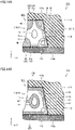
- Figs. 14A and 14B are partially sectional views of the shoe sole in Fig. 8 .
- assembly structures of the shock absorber 1D1 to 1D3 in the shoe sole 110 of the second embodiment will be described in detail below.
- the assembly structure of the shock absorbers 1D1 is representatively illustrated, but the same applies to the assembly structures of the shock absorbers 1D2, 1D3.
- Fig. 14A is a sectional view illustrating the shoe sole 110 of the portion including the through-hole 32 (in Fig. 14A , the through-hole is particularly denoted by reference numeral 32 (13)) communicating with the opening 13 that is located at the end surface on the side of the fixing wall 30 and included in each of the plurality of three-dimensional structure bodies 12.
- Fig. 14B is a sectional view illustrating the shoe sole 110 of the portion including the through-hole 32 (in Fig. 14B , the through-hole is simply indicated by reference numeral 32) communicating with the space surrounding the periphery of the three-dimensional structure body 12.
- the shock absorber 1D1 is fixed to the midsole 111 and the outsole 112 through an adhesive layer 113.
- the upper support 21 is joined to the wall surface on the upper side of the cutout provided in the midsole 111 through the adhesive layer 113
- the fixing wall 30 is joined to the wall surface on the side of the cutout provided in the midsole 111 through the adhesive layer 113.
- the lower support 22 is joined to the upper surface of the outsole 112 through the adhesive layer 113.
- both the wall surface on the upper side of the cutout of the midsole 111 and the upper surface of the upper support 21 are formed in a substantially planar shape, and the shock absorber 1D1 and the midsole 111 are fixed at the portion by bonding the adhesive layer 113 to these surfaces.
- the plurality of through-holes 21a is provided in the upper support 21 as described above, and a part of the adhesive layer 113 enters the plurality of through-holes 21a.
- Both the upper surface of the outsole 112 and the lower surface of the lower support 22 are formed in a substantially planar shape, and the shock absorber 1D1 and the outsole 112 are fixed at the portion by bonding the adhesive layer 113 to these surfaces.
- the plurality of through-holes 22a is provided in the lower support 22 as described above, and a part of the adhesive layer 113 enters the plurality of through holes 22a.
- the first opposing surface 111a that is the wall surface on the side of the cutout of the midsole 111 and the second opposing surface 31 that is the outer surface of the fixing wall 30 are both formed in the substantially planar shape, and the shock absorber 1D1 and the midsole 111 are fixed at the portion by bonding the adhesive layer 113 to these surfaces.
- the plurality of through-holes 32 (13) are made in the fixing wall 30 as described above, and a part of the adhesive layer 113 enters the plurality of through-holes 32 (13).
- Fig. 14A the plurality of through-holes 32 (13) are made in the fixing wall 30 as described above, and a part of the adhesive layer 113 enters the plurality of through-holes 32 (13).
- the plurality of through-holes 32 are made in the fixing wall 30 as described above, and a part of the adhesive layer 113 enters the plurality of through-holes 32 (13).
- an increase in bonding strength at the portion is achieved by an increase in bonding area and a kind of anchor effect.
- the upper support 21, the lower support 22, and the fixing wall 30 are firmly fixed to the midsole 111 and the outsole 112, and the shock absorbers 1D1 to 1D3 can be effectively prevented from peeling off from the midsole 111 and the outsole 112. Furthermore, by providing the plurality of through-holes 21a, 22a, 32 in the upper support 21, the lower support 22, and the fixing wall 30, the joint strength at the portion is increased, and the shoe sole 110 having excellent durability and the shoe 100 including the shoe sole 110 can be obtained.
- the first opposing surface 111a that is the wall surface on the side of the cutout of the midsole 111 is inclinedly provided so as to be inclined with respect to the direction (that is, the thickness direction (Z-axis direction) of the sole body including the midsole 111 and the outsole 112) orthogonal to the tread 112a, and more specifically, the first opposing surface 111a is inclinedly provided such that the lower end of the first opposing surface 111a is located inside the sole body and such that the upper end of the first opposing surface 111a is located outside the sole body.
- the fixing wall 30 of the shock absorber 1D1 is provided to be inclined with respect to the thickness direction of the sole body such that the second opposing surface 31 is parallel to the first opposing surface 111a.
- the fixing wall 30 inclined with respect to the thickness direction of the sole body can be formed by arranging the plurality of three-dimensional structure bodies 12 in a row along the fixing wall 30 such that each of the plurality of three-dimensional structure bodies 12 included in the shock absorbing portion 10 is formed of the unit structure body having the trapezoidal space as the unit space S as described above and such that the above-described inclined ends of the plurality of three-dimensional structure bodies 12 are connected to the fixing wall 30.
- the rigidity in the thickness direction of the sole body at the portion can be significantly reduced as compared with the case where the fixing wall 30 of the shock absorber 1D1 is provided so as to be parallel to the thickness direction of the sole body.
- the increase in rigidity can be effectively prevented at the boundary between the midsole 111 and the shock absorber 1D1 as compared with the periphery, and the shoe sole 110 having excellent wearing comfortableness and the shoe 100 including the shoe sole 110 can be provided.
- the shock absorbers 1D1 to 1D3 include the reinforcing portions 40, 40', 40" in addition to the shock absorbing portion 10, the upper support 21, the lower support 22, and the fixing wall 30.
- the lower support 22 when viewed along the thickness direction (that is, the Z-direction in the drawing) of the sole body, which is the direction orthogonal to the tread 112a, the lower support 22 has a protruding region protruding outward from the end on the side of the lower support 22 of the three-dimensional structure body 12.
- the protruding region becomes the portion having extremely small rigidity as compared with the surroundings, and is easily deformed by the application of the external force, and as a result, the portion may be damaged relatively early by repeated use or the like.
- the reinforcing portion 40 is provided so as to connect the portion close to the end on the side of the lower support 22 of the three-dimensional structure body 12 and the lower support 22 of the portion corresponding to the protruding region.
- the reinforcing portion 40 is formed by embedding a part of the space surrounding the periphery of the three-dimensional structure body 12, and the rigidity in the portion is increased by forming the reinforcing portion 40, and the lower support 22 of the portion corresponding to the protruding region can be prevented from being excessively deformed.
- the shoe sole 110 having the excellent durability and the shoe 100 including the shoe sole 110 can be provided by adopting this configuration. Because the reinforcing portion 40 also has a function of preventing excessive compressive deformation of the shock absorbing portion 10 as a secondary function, when this configuration is adopted, the shoe sole 110 having the excellent durability and the shoe 100 including the shoe sole 110 can also be obtained in this respect.
- the reinforcing portion 40' is provided so as to connect the portion closer to the end on the side of the upper support 21 of the three-dimensional structure body 12 and the upper support 21. Similarly to the reinforcing portion 40, the reinforcing portion 40' is also formed by embedding a part of the space surrounding the periphery of the three-dimensional structure body 12. When configured in such manner, the shock absorbing portion 10 can be prevented from being excessively compressed and deformed, and the shoe sole 110 having the excellent durability and the shoe 100 including the shoe sole 110 can be obtained.
- the reinforcing portion 40" is formed by embedding a part of the space surrounding the periphery of the three-dimensional structure body 12 so as to connect adjacent three-dimensional structure bodies 12.
- Figs. 15A and 15B are perspective views illustrating simulation models of the shoe sole according to a second comparative example and a fourth example
- Fig. 16 is a graph illustrating a simulation result of the shock absorbing performance of the shoe sole according to the second comparative example and the fourth example.
- a second verification test conducted by the present inventor will be described in detail in order to check the effect obtained by inclining the fixing wall 30 with respect to the thickness direction of the sole body.
- the simulation models of the shoe sole of the second comparative example and the fourth example were specifically produced, the case where the external force was applied to these simulation models along a predetermined direction was assumed, and the behavior in that case was individually analyzed by simulation. More specifically, for each of these simulation models, what is called a load-displacement curve at the boundary between the midsole and shock absorber was obtained.
- a shock absorber 1Y having a three-dimensional structure body 12Y in which the shape in the unloaded state is obtained by stretching the regular hexahedron shaped unit space S' of the shock absorber 1' as the reference in the Y-axis direction, further slightly stretching the unit space S' in the Z-axis direction, and changing the shape of the unit structure body U' so as to follow the shape change to the unit space S' having the rectangular parallelepiped shape is used in a simulation model 110Y of the shoe sole of the second comparative example.
- the shock absorber 1Y includes the upper support 21 and the fixing wall 30, and the fixing wall 30 is configured of a vertical wall parallel to the thickness direction of the sole body.
- the second opposing surface 31 (see Figs. 14A and 14B ) provided in the fixing wall 30 is configured of the surface parallel to the thickness direction of the sole body, and as a result, the first opposing surface 111a (see Figs. 14A and 14B ) that is the wall surface on the side of the cutout of the midsole 111 is also configured of the surface parallel to the thickness direction of the sole body.
- a shock absorber 1E having a three-dimensional structure body 12E in which the shape in the unloaded state is obtained by changing the shape of the unit structure body U' so as to follow the shape change of the regular hexahedron shaped unit space S' of the shock absorber 1' as the reference to the trapezoidal shape is used in a simulation model 110A of the shoe sole of the fourth example.
- the shock absorber 1E includes the upper support 21 and the fixing wall 30, and the fixing wall 30 is configured of a wall inclined with respect to the thickness direction of the sole body.
- the second opposing surface 31 (see Figs. 14A and 14B ) provided in the fixing wall 30 is configured of the surface inclined with respect to the thickness direction of the sole body, and as a result, the first opposing surface 111a (see Figs. 14A and 14B ) that is the wall surface on the side of the cutout of the midsole 111 is also configured of the surface inclined with respect to the thickness direction of the sole body.
- simulation model 110Y of the shoe sole of the second comparative example and the simulation model 110A of the fourth example all conditions were set to be the same except for the points described above.
- the direction of the external force applied to the simulation models 110Y, 110A of the shoe sole of the second comparative example and the fourth example was set to the vertical direction (that is, the Z-axis direction).
- Fig. 17 is a perspective view illustrating a shock absorber included in a shoe sole according to a first modification.
- a shock absorber 1D1' included in the shoe sole of the first modification based on the second embodiment will be described below.
- the shock absorber 1D1' is provided in the shoe sole 110 instead of the shock absorber 1D1 included in the shoe sole 110 of the second embodiment.
- the shock absorber 1D1' included in the shoe sole of the first modification is different from the shock absorber 1D1 included in the shoe sole 110 of the second embodiment only in that the reinforcing portions 40, 40', 40" are not provided. That is, the shock absorber 1D1' includes only the shock absorbing portion 10 configured of the plurality of three-dimensional structure bodies 12, the upper support 21 and the lower support 22 as the support 20, and the fixing wall 30.
- the effect of the first embodiment can be obtained, and the increase in rigidity at the boundary between the midsole 111 and the shock absorber 1D1' as compared with the periphery can be effectively prevented, whereby the shoe sole excellent wearing comfortableness and the shoe including the shoe sole can be obtained.
- Fig. 18 is a perspective view illustrating a shock absorber included in a shoe sole according to a second modification.
- a shock absorber 1D1" included in the shoe sole of the second modification based on the second embodiment will be described below.
- the shock absorber 1D1" is provided in the shoe sole 110 instead of the shock absorber 1D1 included in the shoe sole 110 of the second embodiment.
- the shock absorber 1D1" included in the shoe sole of the second modification is different from the shock absorber 1D1' included in the shoe sole of the first modification only in that the extension portion 50 is provided.
- the extension portion 50 has a plate shape, and extends from the connecting portion between the lower support 22 and the fixing wall 30 along the extending direction of the lower support 22 so as to exceed the fixing wall 30.
- the shock absorber 1D1" is a region increasing the joint area with respect to the midsole 111 and the outsole 112, and the shock absorber 1D1" is more firmly joined to the midsole 111 and the outsole 112 by providing the extension portion 50.
- the effect of the first embodiment can be obtained, and it is possible to effectively suppress the increase in rigidity at the boundary between the midsole 111 and the shock absorber 1D1" can be effectively prevented as compared with the periphery, so that not only the shoe sole having the excellent wearing comfortableness and the shoe including the shoe sole can be obtained, but also the shoe sole having the excellent durability and the shoe including the shoe sole can be obtained.
- the shock absorber includes the shock absorbing portion having the three-dimensional shape formed by the wall in which the outer shape is defined by the pair of parallel curved surfaces.
- the shock absorbing portion includes at least one three-dimensional structure body obtained by changing the shape of the unit structure body thickened based on the unit structure of the Schwartz P structure.
- the shape of the three-dimensional structure body in the unloaded state is a shape obtained by changing the shape of the unit structure body so as to follow the shape change of the unit space body, which is a regular hexahedron shaped space occupied by the unit structure body, into a trapezoidal space.
- the shape of the three-dimensional structure body in the unloaded state may be the shape obtained by changing the shape of the unit structure body so as to follow the shape change of the unit space that is the regular hexahedron shaped space to the trapezoidal space when each of surfaces included in one of two pairs of opposing surfaces excluding one pair of opposing surfaces located in the axial direction among the three pairs of opposing surfaces.
- the shape of the three-dimensional structure body in the unloaded state may be the shape obtained by changing the shape of the unit structure body so as to follow the shape change of the unit space that is the regular hexahedron shaped space to the trapezoidal space when each of surfaces included in two pairs of opposing surfaces excluding one pair of opposing surfaces located in the axial direction among the three pairs of opposing surfaces.
- the flat plate-shaped support orthogonal to the axial direction may be provided on at least one of the pair of ends located in the axial direction of the three-dimensional structure body.
- the support when viewed along the axial direction, may have the protruding region that protrudes outward from the end on the support side of the three-dimensional structure body, and in this case, the reinforcing portion preventing the deformation of the support in the protruding region may be provided so as to connect the portion of the three-dimensional structure body close to the end on the support side and the support of the portion corresponding to the protruding region.
- the shock absorbing portion may include the plurality of the three-dimensional structure bodies, and in this case, the plurality of three-dimensional structure bodies may be arranged in a row such that the axial directions thereof are located substantially in parallel.
- the shock absorbing portion may include the plurality of the three-dimensional structure bodies, and in this case, the plurality of three-dimensional structure bodies may be arranged in the matrix shape such that the axial directions thereof are located substantially in parallel.
- the shoe sole according to one aspect of the present disclosure includes the shock absorber according to an aspect of the present disclosure.
- the shock absorber may be disposed such that the axial direction in which the shock absorbing portion exerts the shock absorbing function by receiving the load is orthogonal to the tread.
- the shoe according to one aspect of the present disclosure includes the shoe sole according to one aspect of the present disclosure and the upper provided above the shoe sole.
- the shock absorber is disposed along a part of the shoe sole.
- the position at which the shock absorber is provided is not limited thereto, and can be appropriately changed.
- the shock absorber may be disposed along the entire circumference of the shoe sole, or the shock absorber may be disposed at the position inside the circumference of the shoe sole.
- the shock absorber may be disposed over the entire area of the shoe sole.
- the shock absorber may be disposed only in any one of the medial foot side portion and the lateral foot side portion of the shoe sole according to the type and use of competition in which the shoe is used.
- shock absorber may be provided between the midsole and the upper, or the shock absorber itself may also serve as the outsole. At this point, when the shock absorber is provided on the entire surface of the shoe sole, the entire midsole may be replaced with the shock absorber.
- the present invention is applied to the shoe including the tongue and the shoelace by way of example.
- the present invention may be applied to a shoe without these components (such as a shoe including a sock-shaped upper) and a shoe sole included in the shoe.
- the shock absorber of the present invention can be used for other shock absorbing applications.
- the shock absorber of the present invention can be used in various applications such as packaging materials, floor materials for buildings (for example, houses), surface materials for paved roads, surface materials for sofas, chairs, and the like, and tires.
Landscapes
- Engineering & Computer Science (AREA)
- General Engineering & Computer Science (AREA)
- Chemical & Material Sciences (AREA)
- Materials Engineering (AREA)
- Mechanical Engineering (AREA)
- Footwear And Its Accessory, Manufacturing Method And Apparatuses (AREA)
- Vibration Dampers (AREA)
Abstract
Description
- This nonprovisional application is based on
Japanese Patent Application No. 2021-105023 filed on June 24, 2021 - The present invention relates to a shock absorber absorbing shock, a shoe sole including the shock absorber, and a shoe including the shoe sole.
- Conventionally, various types of shock absorbers for absorbing shock have been known, and these various types of shock absorbers have been used depending on the application. For example, a shoe may have a shoe sole provided with a shock absorber in order to absorb shock caused upon landing. The shock absorber provided to the shoe sole is typically composed of a member made of resin or rubber.
- In recent years, there have also been developed shoes having a shoe sole provided with a part having a lattice structure, a web structure or the like so that not only a material but also a structure provides an enhanced shock absorbing function. A shoe comprising a shoe sole provided with a part having a lattice structure is disclosed for example in
U.S. Patent Publication No. 2018/0049514 . -
Japanese National Patent Publication No. 2017-527637 - At this point, in general, a property required for the shock absorber includes tending to gradually increase a load when the shock absorber is compressively deformed. When the shock absorber has such the property, the shock absorber is stably displaced in a process of increasing the load applied from the outside, so that excellent shock absorbing performance is obtained. For example, when the shock absorber having such the performance is applied to the shoe sole, the shoe having significantly excellent wearing comfortableness can be obtained.
- Consequently, an object of the present invention is to provide a shock absorber having excellent shock absorbing performance, and a shoe sole and a shoe including the shock absorber.
- The inventor of the present invention has found that the shock absorber made of an elastic material thickened based on a Schwartz P structure, which is one of triple periodic minimum curved surface structures, as a reference has a property that a load rapidly decreases at a time point when compressive displacement reaches a certain value in a case where the shock absorber is compressively deformed. This property is not necessarily preferable in consideration of general use as the shock absorber, and for example, the wearing comfortableness may be impaired when the shock absorber is applied to the shoe sole.
- In this respect, the inventor has conceived that the above-described problem can be solved by changing the shape of a unit structure body of the shock absorber thickened based on the Schwartz P structure in an unloaded state to a predetermined shape, and has completed the present invention.
- A shock absorber according to an aspect of the present disclosure includes a shock absorbing portion having a three-dimensional shape formed by a wall in which an outer shape is defined by a pair of parallel curved surfaces. The shock absorbing portion includes at least one three-dimensional structure body obtained by changing the shape of the unit structure body thickened based on the unit structure of the Schwartz P structure. The shape of the three-dimensional structure body in the unloaded state is a shape obtained by changing the shape of the unit structure body so as to follow the shape change of the unit space body, which is a regular hexahedron shaped space occupied by the unit structure body, into a trapezoidal space.
- The shoe sole of the present invention includes the above-described shock absorber of the present invention.
- The shoe of the present invention includes the shoe sole of the present invention, and an upper provided above the shoe sole.
- The foregoing and other objects, features, aspects and advantages of the present invention will become more apparent from the following detailed description of the present invention when taken in conjunction with the accompanying drawings.
-
-
Fig. 1A is a perspective view illustrating a three-dimensional structure body of a shock absorber according to a first embodiment. -
Fig. 1B is a perspective view illustrating a unit structure body obtained by thickening a unit structure of a Schwartz P structure based on the unit structure. -
Fig. 2A is a front view illustrating the three-dimensional structure body of the shock absorber of the first embodiment. -
Fig. 2B is a left side view illustrating the three-dimensional structure body of the shock absorber of the first embodiment. -
Fig. 2C is a plan view illustrating the three-dimensional structure body of the shock absorber of the first embodiment. -
Fig. 2D is a bottom view illustrating the three-dimensional structure body of the shock absorber of the first embodiment. -
Figs. 3A and 3B are sectional views illustrating the three-dimensional structure body of the shock absorber of the first embodiment. -
Fig. 4A is a perspective view of a shock absorber according to a first comparative example. -
Fig. 4B is a graph illustrating a simulation result of shock absorbing performance of the shock absorber of the first comparative example. -
Fig. 5A is a perspective view of a shock absorber according to a first example. -
Fig. 5B is a graph illustrating a simulation result of the shock absorbing performance of the shock absorber of the first example. -
Fig. 6A is a perspective view of a shock absorber according to a second example. -
Fig. 6B is a front view of the shock absorber of the second example. -
Fig. 6C is a left side view of the shock absorber of the second example. -
Fig. 7A is a perspective view of a shock absorber according to a third example. -
Fig. 7B is a front view of the shock absorber of the third example. -
Fig. 7C is a left side view of the shock absorber of the third example. -
Fig. 8 is a perspective view illustrating a shoe sole and a shoe according to a second embodiment. -
Fig. 9 is a side view illustrating the shoe sole of the second embodiment as viewed from a lateral foot side. -
Fig. 10 is a side view illustrating the shoe sole of the second embodiment as viewed from a medial foot side. -
Fig. 11 is a schematic plan view illustrating a disposition position of the shock absorber in the shoe sole of the second embodiment. -
Fig. 12 is a perspective view illustrating the shock absorber included in the shoe sole of the second embodiment. -
Fig. 13 is an enlarged view illustrating a main part of the shock absorber included in the shoe sole of the second embodiment. -
Figs. 14A and 14B are partially sectional views of the shoe sole of the second embodiment. -
Fig. 15A is a perspective view illustrating a simulation model of the shoe sole according to a second comparative example. -
Fig. 15B is a perspective view illustrating a simulation model of the shoe sole according to a fourth example. -
Fig. 16 is a graph illustrating simulation results of the shock absorbing performance of the shoe soles of the second comparative example and the fourth example. -
Fig. 17 is a perspective view illustrating a shock absorber included in a shoe sole according to a first modification. -
Fig. 18 is a perspective view illustrating a shock absorber included in a shoe sole according to a second modification. - Hereinafter, embodiments of the present invention will be described in detail with reference to the accompanying drawings. In the following embodiments, identical or common portions are identically denoted in the figures, and will not be described repeatedly.
-
Fig. 1A is a perspective view illustrating a three-dimensional structure body of a shock absorber according to a first embodiment, andFig. 1B is a perspective view illustrating a unit structure body obtained by thickening a unit structure of a Schwartz P structure based on the unit structure.Figs. 2A to 2D are a front view, a left side view, a plan view, and a bottom view illustrating the three-dimensional structure body of the shock absorber inFig. 1A as viewed along directions of arrows IIA to IID inFig. 1A .Fig. 3A is a sectional view taken along line IIIA-IIIA inFig. 2B , andFig. 3B is a sectional view taken along line IIIB-IIIB inFig. 2A . With reference toFigs. 1A to 3B , ashock absorber 1 of the first embodiment will be described below. - As illustrated in
Figs. 1A to 3B (however,Fig. 1B is excluded), theshock absorber 1 includes ashock absorbing portion 10 that exhibits a shock absorbing function. Theshock absorbing portion 10 has a three-dimensional shape formed by awall 11 having an external shape defined by a pair of parallel curved surfaces, and has a geometric wall structure having a cavity therein. Theshock absorbing portion 10 includes at least one three-dimensional structure body 12 having a shape in the unloaded state as illustrated in the drawing. - As illustrated in
Fig. 1A , a unit space S occupied by the three-dimensional structure body 12 has a table shape, and the unit space S is defined by a pair of opposing surfaces A1, A2 located in an X-axis direction illustrated in the drawing, a pair of opposing surfaces B1, B2 located in a Y-axis direction illustrated in the drawing, and a pair of opposing surfaces C1, C2 located in a Z-axis direction illustrated in the drawing. Theshock absorbing portion 10 of theshock absorber 1 is intended to exert a shock absorbing function by receiving a load particularly in the Z-axis direction among the X-axis direction, the Y-axis direction, and the Z-axis direction. - The pair of opposing surfaces A1, A2 located in the X-axis direction has the same size and the same shape in a plan view, and each of the pair of opposing surfaces A1, A2 is a trapezoid in which a length LT of an upper side, which is one side of the pair of sides extending in the Y-axis direction, is shorter than a length LB of a lower side that is the other side. The pair of opposing surfaces B1, B2 located in the Y-axis direction has the same size and the same shape in a plan view, and has a rectangular shape. Each of the pair of opposing surfaces C1, C2 located in the Z-axis direction has a rectangular shape in a plan view, but the length LT of the pair of sides extending in the Y-axis direction of one surface C1 is shorter than the length LB of the pair of sides extending in the Y-axis direction of the other surface C2.
- Thus, the unit space S is configured of a trapezoidal space in which the pair of opposing surfaces B1, B2 located in the Y-axis direction is inclined. As a result, the three-
dimensional structure body 12 includes an end on the side where the opposing surfaces B1, B2 are located as an inclined end. - A ratio between the side lengths LT, LB is not particularly limited, but preferably satisfies a condition of 1.1 ≤ LT/LB ≤ 4.0.
- In each of the surfaces A1, A2, B1, B2, C1, C2 included in the three pairs of opposing surfaces, an
opening 13 located at an end of the three-dimensional structure body 12 is located. At this point, inFigs. 1A to 3B (however,Fig. 1B is excluded), in order to easily understand the shape of the three-dimensional structure body 12, end surfaces of the three-dimensional structure body 12 located in each of the X-axis direction, the Y-axis direction, and the Z-axis direction are denoted by a dark color to distinguish the end surfaces from other outer surfaces of the three-dimensional structure body 12. - The three-
dimensional structure body 12 of theshock absorber 1 is obtained by changing the shape of a unit structure body U' of a shock absorber 1' as a reference inFig. 1B , and has a shape inFigs. 1A to 3B (however,Fig. 1B is excluded) in the unloaded state. - As illustrated in
Fig. 1B , the unit structure body U' of the shock absorber 1' as the reference is thickened based on the unit structure of the Schwartz P structure, which is a type of a mathematically defined triple periodic minimum curved surface. Note that a minimal surface is defined as a curved surface of those having a given closed curve as a boundary that is minimal in area. - A unit space S' occupied by the unit structure body U' has a regular hexahedron shape (cubic shape), and the unit space S' is defined by a pair of opposing surfaces A1', A2' located in the X-axis direction, a pair of opposing surfaces B1', B2' located in the Y-axis direction, and a pair of opposing surfaces C1', C2' located in the Z-axis direction. Each of the surfaces A1', A2', B1', B2', C1', C2' included in the three pairs of opposing faces is a square in a plan view.
- The shape of the three-
dimensional structure body 12 of theshock absorber 1 in the unloaded state is a shape obtained by changing the shape of the unit structure body U' so as to follow the change of the shape of the regular hexahedron shaped unit space S' of the shock absorber 1' as the reference into the trapezoidal space. More particularly, the shape of the three-dimensional structure body 12 in the unloaded state is a shape obtained by changing the shape of the unit structure body U' so as to follow the shape change when the shape of the regular hexahedron shaped unit space S' of the shock absorber 1' as the reference is changed to the trapezoidal space by inclining each of the surfaces included in one pair of opposing surfaces B1, B2 located in the Y-axis direction among the three pairs of opposing surfaces. - At this point, as described above, the
shock absorbing portion 10 of theshock absorber 1 may include at least one three-dimensional structure body 12 having the shape in the unloaded state as illustrated in the drawing. - That is, when the
shock absorbing portion 10 is configured of only one type of unit structure body, the one type of the unit structure body is configured of the three-dimensional structure body 12 as illustrated in the drawing, and in this case, the number of the three-dimensional structure bodies 12 may be only one or plural. When the number of the three-dimensional structure bodies 12 is plural, the plurality of the three-dimensional structure bodies 12 may be repeatedly arranged along at least one of the X-axis direction, the Y-axis direction, and the Z-axis direction. - In addition, when the
shock absorber 1 is configured of a plurality of types of unit structure bodies, the one type of the unit structure body is configured of the three-dimensional structure body 12 as illustrated in the drawing, and in this case, the number of the three-dimensional structure bodies 12 may be only one or plural. When the number of the three-dimensional structure bodies 12 is plural, the plurality of the three-dimensional structure bodies 12 may be repeatedly arranged with or without another type of unit structure body sandwiched therebetween along at least one of the X-axis direction, the Y-axis direction, and the Z-axis direction. - In addition to the
shock absorbing portion 10, theshock absorber 1 may further include a support 20 (seeFig. 12 and the like), a fixing wall 30 (seeFig. 12 and the like), reinforcingportions Fig. 13 and the like), an extension portion 50 (seeFig. 18 ), and the like, which will be described later. In this case, these regions are provided adjacent to theshock absorbing portion 10 described above. - A method for manufacturing the
shock absorber 1 is not limited, but for example, theshock absorber 1 can be manufactured using a three dimensional additive manufacturing apparatus. - While the
shock absorber 1 may basically be formed of any material having a large elastic force, it is preferably formed of a resin material or a rubber material. More specifically, when theshock absorber 1 is formed of resin, theshock absorber 1 can be formed of, for example, polyolefin resin, an ethylene-vinyl acetate copolymer (EVA), a polyamide-based thermoplastic elastomer (TPA, TPAE), thermoplastic polyurethane (TPU), or a polyester-based thermoplastic elastomer (TPEE). When theshock absorber 1 is formed of rubber, it can be formed for example of butadiene rubber. - The
shock absorber 1 may be composed of a polymer composition. In that case, examples of a polymer to be contained in the polymer composition include olefinic polymers such as olefinic elastomers and olefinic resins. The olefinic polymers for example include polyolefins of polyethylene (e.g., linear low density polyethylene (LLDPE), high density polyethylene (HDPE), and the like), polypropylene, an ethylene-propylene copolymer, a propylene-1-hexene copolymer, a propylene-4-methyl-1-pentene copolymer, a propylene-1-butene copolymer, an ethylene-1-hexene copolymer, an ethylene-4-methyl-pentene copolymer, an ethylene-1-butene copolymer, a 1-butene-1-hexene copolymer, 1-butene-4-methyl-pentene, an ethylene-methacrylic acid copolymer, an ethylene-methyl methacrylate copolymer, an ethylene-ethyl methacrylate copolymer, an ethylene-butyl methacrylate copolymer, an ethylene-methyl acrylate copolymer, an ethylene-ethyl acrylate copolymer, an ethylene-butyl acrylate copolymer, a propylene-methacrylic acid copolymer, a propylene-methyl methacrylate copolymer, a propylene-ethyl methacrylate copolymer, a propylene-butyl methacrylate copolymer, a propylene-methyl acrylate copolymer, a propylene-ethyl acrylate copolymer, a propylene-butyl acrylate copolymer, an ethylene-vinyl acetate copolymer (EVA), a propylene-vinyl acetate copolymer, and the like. - The polymer may be an amide-based polymer such as an amide-based elastomer and an amide-based resin. Examples of the amide-based polymer include
polyamide 6,polyamide 11,polyamide 12, polyamide 66, and polyamide 610. - The polymer may be an ester-based polymer such as an ester-based elastomer and an ester-based resin. Examples of the ester-based polymer include polyethylene terephthalate and polybutylene terephthalate.
- The polymer may be a urethane-based polymer such as a urethane-based elastomer and a urethane-based resin. Examples of the urethane-based polymer include polyester-based polyurethane and polyether-based polyurethane.
- The polymer may be a styrene-based polymer such as a styrene-based elastomer and a styrene-based resin. Examples of the styrene-based elastomer include styrene-ethylene-butylene copolymer (SEB), styrene-butadiene-styrene copolymer (SBS), a hydrogenated product of SBS (styrene-ethylene-butylene-styrene copolymer (SEBS)), styrene-isoprene-styrene copolymer (SIS), a hydrogenated product of SIS (styrene-ethylene-propylene-styrene copolymer (SEPS)), styrene-isobutylene-styrene copolymer (SIBS), styrene-butadiene-styrene-butadiene (SBSB), styrene-butadiene-styrene-butadiene-styrene (SBSBS), and the like. Examples of the styrene-based resin include polystyrene, acrylonitrile styrene resin (AS), and acrylonitrile butadiene styrene resin (ABS).
- Examples of the polymer include acrylic polymers such as polymethylmethacrylate, urethane-based acrylic polymers, polyester-based acrylic polymers, polyether-based acrylic polymers, polycarbonate-based acrylic polymers, epoxy-based acrylic polymers, conjugated diene polymer-based acrylic polymers and hydrogenated products thereof, urethane-based methacrylic polymers, polyester-based methacrylic polymers, polyether-based methacrylic polymers, polycarbonate-based methacrylic polymers, epoxy-based methacrylic polymers, conjugated diene polymer-based methacrylic polymers and hydrogenated products thereof, polyvinyl chloride-based resins, silicone-based elastomers, butadiene rubber (BR), isoprene rubber (IR), chloroprene rubber (CR), natural rubber (NR), styrene-butadiene rubber (SBR), acrylonitrile-butadiene rubber (NBR), butyl rubber (IIR), and the like.
-
Shock absorber 1 of the first embodiment is excellent in shock absorbing performance. Hereinafter, this point will be described in detail based on the result of the first verification test performed by the present inventor. -
Fig. 4A is a perspective view of a shock absorber according to a first comparative example, andFig. 4B is a graph illustrating a simulation result of the shock absorbing performance of the shock absorber of the first comparative example.Fig. 5A is a perspective view of a shock absorber of a first example, andFig. 5B is a graph illustrating a simulation result of the shock absorbing performance of the shock absorber of the first example. - In the first verification test, the models of the shock absorbers of the first comparative example and the first example were specifically designed, it was assumed that the case where external force was applied to these models along a predetermined direction, and a behavior in that case was individually analyzed by simulation. More specifically, what is called a load-displacement curve was obtained for each of these models.
- At this point, as illustrated in
Fig. 4A , ashock absorber 1X of the first comparative example has a three-dimensional structure body 12X in which the shape in the unloaded state is obtained by stretching the regular hexahedron shaped unit space S' of the shock absorber 1' as the reference only in the Z-axis direction, and changing the shape of the unit structure body U' so as to follow the shape change of the unit space S' to the unit space having a rectangular parallelepiped shape. On the other hand, similarly to theshock absorber 1 of the first embodiment, theshock absorber 1A of the first example has a three-dimensional structure body 12A in which the shape in the unloaded state is obtained by changing the shape of the unit structure body U' so as to follow the shape change of the regular hexahedron shaped unit space S' of the shock absorber 1' as the reference when the shape of the regular hexahedron shaped unit space S' is changed to the trapezoidal shape. - More particularly, in the
shock absorber 1X of the first comparative example, the dimensions in the X-axis direction and the Y-axis direction of the three-dimensional structure body 12X as the unit structure body were set to 10 mm, and the dimension in the Z-axis direction of the three-dimensional structure body 12X was set to 20 mm. The thickness ofwall 11 of the three-dimensional structure body 12X was set to 1.52 mm, and the material thereof was assumed to be a urethane-based acrylic polymer having an elastic modulus of 7.1 MPa. - On the other hand, in the
shock absorber 1A of the first example, the dimensions of the three-dimensional structure body 12A as the unit structure body in the X-axis direction and the Z-axis direction were set to 10 mm and 20 mm, and the lengths LT, LB of the three-dimensional structure body 12A inFig. 1A were set to 10 mm and 20 mm. The thickness of thewall 11 of the three-dimensional structure body 12A was set to 2.32 mm, and the material thereof was assumed to be a urethane-based acrylic polymer having an elastic modulus of 7.1 MPa. - In addition, the directions of the external forces applied to the
shock absorbers Figs. 4A and5A exemplarily illustrate the state in which each four of the three-dimensional structure bodies - As illustrated in
Fig. 4B , theshock absorber 1X of the first comparative example has a property that the load rapidly decreases when the compressive displacement reaches a certain value in both the case where the external force is applied in the vertical direction and the case where the external force is applied in the oblique direction. This property is not necessarily preferable in consideration of general use as the shock absorber, and for example, when theshock absorber 1X is applied to the shoe sole, there is a risk that the wearing comfortableness is impaired. - On the other hand, as illustrated in
Fig. 5B , theshock absorber 1A of the first example has a property that the load gradually increases in both the case where the external force is applied in the vertical direction and the case where the external force is applied in the oblique direction. This property is suitable in consideration of general use as the shock absorber, and the shock absorber is stably displaced in the process of increasing the load applied from the outside. Therefore, for example, when theshock absorber 1A is applied to the shoe sole, the shoe having significantly excellent wearing comfortableness can be obtained. - Consequently, using the
shock absorber 1 of the first embodiment, the shock absorber having the excellent shock absorbing performance can be used for various applications. When the three-dimensional structure bodies are arranged in a row likeshock absorber 1A of the first example, it is preferable that the directions (that is, the Z-axis direction) intended to exhibit the shock absorbing function in each of the plurality of three-dimensional structure bodies are disposed substantially parallel to each other. -
Fig. 6A is a perspective view of a shock absorber according to a second example, andFigs. 6B and 6C are a front view and a left side view of the shock absorber inFig. 6A as viewed along directions of arrows VIB and VIC inFig. 6A . With reference toFigs. 6A to 6C , ashock absorber 1B of the second example will be described below. - As illustrated in
Figs. 6A to 6C , theshock absorber 1B of the second example includes two types of three-dimensional structure bodies shock absorber 1 of the first embodiment described above, the shape of each of the two types of three-dimensional structure bodies dimensional structure body 12B is inverted from the three-dimensional structure body 12A in the Z-axis direction. The three-dimensional structure body 12A is the same as the three-dimensional structure body 12A included in theshock absorber 1A of the first example. - In the
shock absorber 1B of the second example, each four of the three-dimensional structure bodies dimensional structure bodies shock absorber 1B is substantially a parallelogram when viewed along the X-axis direction (seeFig. 6B ). - Also in the
shock absorber 1B configured as described above, similarly to theshock absorber 1 of the first embodiment, the shock absorber having the excellent shock absorbing performance can be used for various applications. When the three-dimensional structure bodies are arranged in a matrix shape, it is preferable that the directions (that is, the Z-axis direction) intended to exhibit the shock absorbing function in each of the plurality of three-dimensional structure bodies are disposed substantially parallel to each other. -
Fig. 7A is a perspective view of a shock absorber according to a third example, andFigs. 7B and 7C are a front view and a left side view of the shock absorber inFig. 7A as viewed along directions of arrows VIIB and VIIC inFig. 7A . With reference toFigs. 7A to 7C , ashock absorber 1C of the third example will be described below. - As illustrated in
Figs. 7A to 7C , theshock absorber 1C of the third example includes two types of three-dimensional structure bodies shock absorber 1 of the first embodiment, the shape of the three-dimensional structure body 12A in the unloaded state is the shape obtained by changing the shape of the unit structure body U' so as to follow the shape of the regular hexahedron shaped unit space S' of the shock absorber 1' as the reference when the shape of the unit space S' is changed to the trapezoidal shape of the shock absorber 1'. Unlike theshock absorber 1 of the first embodiment, the shape of the remaining three-dimensional structure body 12M in the unloaded state is the shape obtained by changing the shape of the unit structure body U' so as to follow the shape of the regular hexahedron shaped unit space S' of the shock absorber 1' as the reference when the shape of the unit space S' is changed to the unit space having the flat rectangular parallelepiped shape. The three-dimensional structure body 12A is the same as the three-dimensional structure body 12A included in theshock absorber 1A of the first example. - In the
shock absorber 1C of the third example, each four of the three-dimensional structure bodies dimensional structure body 12M is arranged between two rows including the three-dimensional structure body 12A, so that the three-dimensional structure bodies shock absorber 1C is substantially trapezoidal as a whole when viewed along the X-axis direction (seeFig. 7B ). - Also in the
shock absorber 1C configured as described above, similarly to theshock absorber 1 of the first embodiment, the shock absorber having the excellent shock absorbing performance can be used for various applications. When the three-dimensional structure bodies are arranged in a matrix shape, it is preferable that the directions (that is, the Z-axis direction) intended to exhibit the shock absorbing function in each of the plurality of three-dimensional structure bodies are disposed substantially parallel to each other. - In the first embodiment, the description has been given by exemplifying the case where the shape of the three-
dimensional structure bodies - For example, the shape of the three-dimensional structure body in the unloaded state may be the shape obtained by changing the shape of the regular hexahedron shaped unit space S' of the shock absorber 1' as the reference to the trapezoidal shape by inclining not only the surfaces included in the pair of opposing surfaces B1, B2 located in the Y-axis direction among the three pairs of opposing surfaces but also the surfaces included in the pair of opposing surfaces A1, A2 located in the X-axis direction so as to change the shape to the trapezoidal space, or in addition to this, when the shape of the unit structure body U' is changed to the substantially trapezoidal shape by slightly inclining or curving the pair of opposing surfaces C1, C2 located in the Z-axis direction so as to change the shape to the substantially trapezoidal space, the shape may be obtained by changing the shape of the unit structure body U' so as to follow this.
- When the three-dimensional structure body has any of these shapes, similarly to
shock absorber 1 of the first embodiment, the shock absorber having the excellent shock absorbing performance can be used for various applications. -
Fig. 8 is a perspective view illustrating a shoe sole and a shoe according to a second embodiment.Figs. 9 and10 are side views of the shoe sole inFig. 8 as viewed from a lateral foot side and a medial foot side.Fig. 11 is a schematic plan view illustrating a disposition position of the shock absorber in the shoe sole inFig. 8 .
With reference toFigs. 8 to 11 , ashoe sole 110 of the second embodiment and a schematic configuration of ashoe 100 including the shoe sole 110 will be described. - As illustrated in
Fig. 8 , theshoe 100 includes theshoe sole 110 and an upper 120. Theshoe sole 110 is a member that covers the sole of a foot and has a generally flat shape. The upper 120 has a shape that at least covers the entirety of a portion of a foot inserted in the shoe that is located on the side of the bridge of the foot, and the upper 120 is located above theshoe sole 110. - The upper 120 includes an
upper body 121, atongue 122, and ashoelace 123. Of these, thetongue 122 and theshoelace 123 are both fixed to or attached to theupper body 121. - The
upper body 121 has an upper portion provided with an upper opening for exposing an upper portion of an ankle and a portion of the bridge of a foot. Theupper body 121 has a lower portion provided with a lower opening covered with the shoe sole 110 as an example and has a lower end French-seamed or the like to form a bottom portion as another example. - The
tongue 122 is fixed to theupper body 121 by sewing, welding, bonding, or a combination thereof so as to cover a portion of the upper opening provided in theupper body 121 that exposes a portion of the bridge of a foot. For theupper body 121 and thetongue 122, woven fabric, knitted fabric, nonwoven fabric, synthetic leather, resin, or the like is used for example, and for a shoe required to be air permeable and lightweight, in particular, a double raschel warp knitted fabric with a polyester yarn knitted therein is used. - The
shoelace 123 is composed of a member in the form of a string for drawing portions of a peripheral edge of the upper opening provided to theupper body 121 and exposing a portion of the bridge of a foot together in the direction of the width of the foot, and theshoelace 123 is passed through a plurality of hole provided through the peripheral edge of the upper opening. When a foot is inserted in theupper body 121 and theshoelace 123 is tightened, theupper body 121 can be brought into close contact with the foot. - As illustrated in
Figs. 8 to 11 , theshoe sole 110 includes amidsole 111 as a sole body, anoutsole 112, and shock absorbers 1D1 to 1D3. - The
midsole 111 includes an upper surface, a lower surface, and side surfaces connecting the upper surface and the lower surface, and constitutes an upper portion of theshoe sole 110. The upper surface of themidsole 111 is joined to the upper 120. - The
midsole 111 preferably has an appropriate strength and also excellently absorbs shock, and from this viewpoint, themidsole 111 can be a member for example of resin or rubber, and suitably composed of a foam material or a non-foam material such polyolefin resin, an ethylene-vinyl acetate copolymer (EVA), polyamide-based thermoplastic elastomer (TPA, TPAE), thermoplastic polyurethane (TPU), polyester-based thermoplastic elastomer (TPEE), and the like, in particular. - The
outsole 112 includes an upper surface and a lower surface as atread 112a, and constitutes a lower portion of theshoe sole 110. Theoutsole 112 is mainly joined to themidsole 111. - The
outsole 112 preferably provides excellent abrasion resistance and excellent grip, and from this viewpoint, theoutsole 112 can be made of rubber, for example. A tread pattern may be provided on a lower surface of theoutsole 112, or thetread 112a, from the viewpoint of providing enhanced grip. - The shock absorber 1D1 to 1D3 is disposed so as to be aligned with the
midsole 111 in the direction intersecting the thickness direction (Z-axis direction) of the sole body including themidsole 111 and theoutsole 112, and more specifically, is disposed in a cutout provided at a predetermined position of themidsole 111. Thus, the shock absorber 1D1 to 1D3 is sandwiched between themidsole 111 and theoutsole 112 in the thickness direction of the sole body. The shock absorber 1D1 to 1D3 is joined to themidsole 111 and theoutsole 112 with an adhesive as described later, and a part of the shock absorber 1D1 to 1D3 is located so as to be exposed on a peripheral surface of theshoe sole 110. - As illustrated in
Figs. 9 to 11 , in a front-back direction (a horizontal direction inFigs. 9 and10 , a vertical direction inFig. 11 ) that is a direction matched with a length direction of a foot of a wearer in a plan view, theshoe sole 110 is divided into a forefoot R1 supporting toe and ball of the foot of the wearer, a midfoot R2 supporting an arch of the foot of the wearer, and a rearfoot R3 supporting a heel of the foot of the wearer. - When a position corresponding to 40% of a dimension in the front-rear direction of the shoe sole 110 from the front-side end is set as a first boundary position, and a position corresponding to 80% of the dimension in the front-rear direction of the shoe sole 110 from the front-side end is set as a second boundary position with respect to the front-side end of the
shoe sole 110, the forefoot R1 corresponds to a portion included between the front-side end and the first boundary position along the front-rear direction, the midfoot R2 corresponds to a portion included between the first boundary position and the second boundary position along the front-rear direction, and the rearfoot R3 corresponds to a portion included between the second boundary position and the rear-side end of the shoe sole along the front-rear direction. - In addition, as illustrated in
Fig. 11 , theshoe sole 110 is divided into a portion on the medial foot side (a portion on the S1 side inFig. 11 ) that is the median side (that is, the side close to the median line) in the anatomical normal position of the foot and a portion on the lateral foot side (a portion on the S2 side inFig. 11 ) that is the opposite side (that is, the side far from the median line) to the median side in the anatomical normal position of the foot, along the horizontal direction (the horizontal direction inFig. 11 ) that is the direction matched with the foot width direction of the foot of the wearer in a plan view. - As illustrated in
Figs. 8 to 11 , themidsole 111 extends in the front-rear direction from the forefoot R1 to the rearfoot R3 through the midfoot R2. Theoutsole 112 includes a portion disposed so as to straddle the forefoot R1 and the front position in the front-rear direction of the midfoot R2, and a portion disposed so as to straddle the rear position in the front-rear direction of the midfoot R2 and the rearfoot R3. - The shock absorber 1D1 is located along an edge of the shoe sole 110 on the lateral foot side so as to straddle a portion closer to the rearfoot R3 of the midfoot R2 and the rearfoot R3. The shock absorber 1D2 is located along the edge of the shoe sole 110 on the medial foot side so as to straddle a portion closer to the rearfoot R3 of the midfoot R2 and the rearfoot R3. The shock absorber 1D3 is located along the edge of the shoe sole 110 on the lateral foot side so as to straddle a portion close to the midfoot R2 of the forefoot R1 and a portion close to the forefoot R1 of the midfoot R2.
-
Fig. 12 is a perspective view illustrating the shock absorber included in the shoe sole inFig. 8 , andFig. 13 is an enlarged view of a region XIII inFig. 12 . With reference toFigs. 12 and13 , a detailed configuration of the shock absorbers 1D1 to 1D3 will be described below. - As illustrated in
Figs. 12 and13 , each of the shock absorbers 1D1 to 1D3 has a configuration similar to theshock absorber 1 of the first embodiment, and includes theshock absorbing portion 10. Theshock absorbing portion 10 has a three-dimensional shape formed by thewall 11 having the external shape defined by a pair of parallel curved surfaces, and includes the plurality of three-dimensional structure bodies 12 as the unit structure body. - Each of the plurality of three-
dimensional structure bodies 12 has a shape obtained by changing the shape of the unit structure body U' so as to follow the change in the shape of the regular hexahedron shaped unit space S' (seeFig. 1A ) of the shock absorber 1' as the reference into the trapezoidal space. In each of the shock absorbers 1D1 to 1D3, the plurality of three-dimensional structure bodies 12 are provided in a line in the direction along the edge of theshoe sole 110. - At this point, each of the plurality of three-
dimensional structure bodies 12 is provided such that the direction (that is, the Z-axis direction) in which a shock absorbing function is intended to be exerted is all directed in the direction orthogonal to tread 112a of theoutsole 112. With such the configuration, the load applied to the shoe sole 110 from the sole and the ground at the time of landing is absorbed by deformation of theshock absorbing portion 10 including the three-dimensional structure body 12 with a large displacement amount, and the load applied from the shoe sole 110 to the sole is reduced, and high shock absorbing performance is obtained. - The shock absorbers 1D1 to 1D3 includes the
support 20 and the fixingwall 30 in addition to theshock absorbing portion 10. Both thesupport 20 and the fixingwall 30 are formed in a plate shape, and provided integrally with theshock absorbing portion 10 adjacent to theshock absorbing portion 10. The shock absorbers 1D1 to 1D3 are formed of a single member formed of theshock absorbing portion 10, thesupport 20, and the fixingwall 30 that are continuously connected to each other. - The
support 20 is provided so as to be located in the direction (that is, the Z-axis direction) in which each of the plurality of three-dimensional structure bodies 12 of the shock absorbers 1D1 to 1D3 is intended to exhibit the shock absorbing function, and includes anupper support 21 on the side on which the upper 120 is located when viewed from theshock absorbing portion 10 and alower support 22 on the side on which theoutsole 112 is located when viewed from theshock absorbing portion 10. Thus, theshock absorbing portion 10 is sandwiched between theupper support 21 and thelower support 22. - A plurality of through-
holes 21a are made in theupper support 21. The plurality of through-holes 21a are associated with and communicate withopenings 13 that are located on the end surface on the side of theupper support 21 and included in the plurality of three-dimensional structure bodies 12. On the other hand, a plurality of through-holes 22a (seeFig. 14A ) are also made in thelower support 22. The plurality of through-holes 22a are associated with and communicate with theopenings 13 that are located on the end surface on the side of thelower support 22 and included in the plurality of three-dimensional structure bodies 12. - The fixing
wall 30 is provided so as to be located in the direction intersecting the direction (that is, the Z-axis direction) in which each of the plurality of three-dimensional structure bodies 12 of the shock absorbers 1D1 to 1D3 is intended to exhibit the shock absorbing function, and more specifically, is provided in the portion of the shock absorbers 1D1 to 1D3 other than the portion exposed on the peripheral surface of theshoe sole 110. Thus, the end surface of theshock absorbing portion 10 located on the side on themidsole 111 of the peripheral surface is covered with the fixingwall 30. - The fixing
wall 30 includes a second opposingsurface 31 that is an exposed surface thereof. A plurality of through-holes 32 are made in the fixingwall 30. The plurality of through-holes 32 include those that are associated with and communicate with theopenings 13 that are located on the end surface on the side of the fixingwall 30 and included in the plurality of three-dimensional structure bodies 12. In addition, the plurality of through-holes 32 do not correspond to theopenings 13, and include a plurality of through-holes communicating with the space surrounding the periphery of the three-dimensional structure body 12 (the through-hole 32 will be described later in detail). - The plurality of through-
holes upper support 21, thelower support 22, and the fixingwall 30 mainly serve as discharge ports discharging the uncured resin at the time of manufacturing when the shock absorbers 1D1 to 1D3 are manufactured using the three-dimensional additive manufacturing method. That is, because the through-holes dimensional structure body 12 of theshock absorbing portion 10 and the space surrounding the periphery of the three-dimensional structure body 12, the uncured resin can be discharged through the through-holes shock absorbing portion 10 having the desired shape can be shaped with high dimensional accuracy. - The
upper support 21 and the fixingwall 30 are both regions fixed to themidsole 111, and thelower support 22 is a region fixed to theoutsole 112. That is, because theshock absorbing portion 10 including the plurality of three-dimensional structure bodies 12 has the geometric wall structure as described above, when theshock absorbing portion 10 is fixed by directly bonding theshock absorbing portion 10 to themidsole 111 or theoutsole 112 as it is, the deformation of the plurality of three-dimensional structure bodies 12 is hindered, and the desired shock absorbing performance cannot be obtained. - In this respect, by integrally providing the
upper support 21, thelower support 22, and the fixingwall 30 with respect to theshock absorbing portion 10, the shock absorbers 1D1 to 1D3 can be fixed to themidsole 111 or theoutsole 112 by adhesion while the deformation of the plurality of three-dimensional structure bodies 12 is prevented, and the desired shock absorbing performance can be obtained. -
Figs. 14A and 14B are partially sectional views of the shoe sole inFig. 8 .
With reference toFigs. 14A and 14B , assembly structures of the shock absorber 1D1 to 1D3 in theshoe sole 110 of the second embodiment will be described in detail below. InFigs. 14A and 14B , the assembly structure of the shock absorbers 1D1 is representatively illustrated, but the same applies to the assembly structures of the shock absorbers 1D2, 1D3. - At this point,
Fig. 14A is a sectional view illustrating theshoe sole 110 of the portion including the through-hole 32 (inFig. 14A , the through-hole is particularly denoted by reference numeral 32 (13)) communicating with theopening 13 that is located at the end surface on the side of the fixingwall 30 and included in each of the plurality of three-dimensional structure bodies 12. On the other hand,Fig. 14B is a sectional view illustrating theshoe sole 110 of the portion including the through-hole 32 (inFig. 14B , the through-hole is simply indicated by reference numeral 32) communicating with the space surrounding the periphery of the three-dimensional structure body 12. - As illustrated in
Figs. 14A and 14B , the shock absorber 1D1 is fixed to themidsole 111 and theoutsole 112 through anadhesive layer 113. Specifically, in the shock absorber 1D1, theupper support 21 is joined to the wall surface on the upper side of the cutout provided in themidsole 111 through theadhesive layer 113, and the fixingwall 30 is joined to the wall surface on the side of the cutout provided in themidsole 111 through theadhesive layer 113. In the shock absorber 1D1, thelower support 22 is joined to the upper surface of theoutsole 112 through theadhesive layer 113. - More specifically, both the wall surface on the upper side of the cutout of the
midsole 111 and the upper surface of theupper support 21 are formed in a substantially planar shape, and the shock absorber 1D1 and themidsole 111 are fixed at the portion by bonding theadhesive layer 113 to these surfaces. As illustrated inFig. 14A , the plurality of through-holes 21a is provided in theupper support 21 as described above, and a part of theadhesive layer 113 enters the plurality of through-holes 21a. Thus, an increase in bonding strength at the portion is achieved by an increase in bonding area and a kind of anchor effect. - Both the upper surface of the
outsole 112 and the lower surface of thelower support 22 are formed in a substantially planar shape, and the shock absorber 1D1 and theoutsole 112 are fixed at the portion by bonding theadhesive layer 113 to these surfaces. As illustrated inFig. 14A , the plurality of through-holes 22a is provided in thelower support 22 as described above, and a part of theadhesive layer 113 enters the plurality of throughholes 22a. Thus, an increase in bonding strength at the portion is achieved by an increase in bonding area and a kind of anchor effect. - Furthermore, the first opposing
surface 111a that is the wall surface on the side of the cutout of themidsole 111 and the second opposingsurface 31 that is the outer surface of the fixingwall 30 are both formed in the substantially planar shape, and the shock absorber 1D1 and themidsole 111 are fixed at the portion by bonding theadhesive layer 113 to these surfaces. As illustrated inFig. 14A , the plurality of through-holes 32 (13) are made in the fixingwall 30 as described above, and a part of theadhesive layer 113 enters the plurality of through-holes 32 (13). In addition, as illustrated inFig. 14B , the plurality of through-holes 32 are made in the fixingwall 30 as described above, and a part of theadhesive layer 113 enters the plurality of through-holes 32 (13). Thus, an increase in bonding strength at the portion is achieved by an increase in bonding area and a kind of anchor effect. - As described above, the
upper support 21, thelower support 22, and the fixingwall 30 are firmly fixed to themidsole 111 and theoutsole 112, and the shock absorbers 1D1 to 1D3 can be effectively prevented from peeling off from themidsole 111 and theoutsole 112. Furthermore, by providing the plurality of through-holes upper support 21, thelower support 22, and the fixingwall 30, the joint strength at the portion is increased, and the shoe sole 110 having excellent durability and theshoe 100 including the shoe sole 110 can be obtained. - At this point, as illustrated in
Figs. 14A and 14B , in theshoe sole 110 of the second embodiment, the first opposingsurface 111a that is the wall surface on the side of the cutout of themidsole 111 is inclinedly provided so as to be inclined with respect to the direction (that is, the thickness direction (Z-axis direction) of the sole body including themidsole 111 and the outsole 112) orthogonal to thetread 112a, and more specifically, the first opposingsurface 111a is inclinedly provided such that the lower end of the first opposingsurface 111a is located inside the sole body and such that the upper end of the first opposingsurface 111a is located outside the sole body. On the other hand, the fixingwall 30 of the shock absorber 1D1 is provided to be inclined with respect to the thickness direction of the sole body such that the second opposingsurface 31 is parallel to the first opposingsurface 111a. - The fixing
wall 30 inclined with respect to the thickness direction of the sole body can be formed by arranging the plurality of three-dimensional structure bodies 12 in a row along the fixingwall 30 such that each of the plurality of three-dimensional structure bodies 12 included in theshock absorbing portion 10 is formed of the unit structure body having the trapezoidal space as the unit space S as described above and such that the above-described inclined ends of the plurality of three-dimensional structure bodies 12 are connected to the fixingwall 30. - As described above, because a boundary between the
midsole 111 and the shock absorber 1D1 is inclined with respect to the thickness direction of the sole body, the rigidity in the thickness direction of the sole body at the portion can be significantly reduced as compared with the case where the fixingwall 30 of the shock absorber 1D1 is provided so as to be parallel to the thickness direction of the sole body. - Consequently, with such the configuration, the increase in rigidity can be effectively prevented at the boundary between the
midsole 111 and the shock absorber 1D1 as compared with the periphery, and the shoe sole 110 having excellent wearing comfortableness and theshoe 100 including the shoe sole 110 can be provided. - At this point, as illustrated in
Figs. 12 to 14B (in particular,Figs. 13 ,14A, and 14B ), in theshoe sole 110 of the second embodiment, the shock absorbers 1D1 to 1D3 include the reinforcingportions shock absorbing portion 10, theupper support 21, thelower support 22, and the fixingwall 30. - More particularly, in the
shoe sole 110, when viewed along the thickness direction (that is, the Z-direction in the drawing) of the sole body, which is the direction orthogonal to thetread 112a, thelower support 22 has a protruding region protruding outward from the end on the side of thelower support 22 of the three-dimensional structure body 12. When no treatment is performed, the protruding region becomes the portion having extremely small rigidity as compared with the surroundings, and is easily deformed by the application of the external force, and as a result, the portion may be damaged relatively early by repeated use or the like. - In the
shoe sole 110 of the second embodiment, as illustrated inFigs. 13 and14A , in order to prevent the deformation of thelower support 22 in the protruding region, the reinforcingportion 40 is provided so as to connect the portion close to the end on the side of thelower support 22 of the three-dimensional structure body 12 and thelower support 22 of the portion corresponding to the protruding region. The reinforcingportion 40 is formed by embedding a part of the space surrounding the periphery of the three-dimensional structure body 12, and the rigidity in the portion is increased by forming the reinforcingportion 40, and thelower support 22 of the portion corresponding to the protruding region can be prevented from being excessively deformed. - Consequently, the shoe sole 110 having the excellent durability and the
shoe 100 including the shoe sole 110 can be provided by adopting this configuration. Because the reinforcingportion 40 also has a function of preventing excessive compressive deformation of theshock absorbing portion 10 as a secondary function, when this configuration is adopted, the shoe sole 110 having the excellent durability and theshoe 100 including the shoe sole 110 can also be obtained in this respect. - On the other hand, as illustrated in
Figs. 13 and14A , the reinforcing portion 40' is provided so as to connect the portion closer to the end on the side of theupper support 21 of the three-dimensional structure body 12 and theupper support 21. Similarly to the reinforcingportion 40, the reinforcing portion 40' is also formed by embedding a part of the space surrounding the periphery of the three-dimensional structure body 12. When configured in such manner, theshock absorbing portion 10 can be prevented from being excessively compressed and deformed, and the shoe sole 110 having the excellent durability and theshoe 100 including the shoe sole 110 can be obtained. - Furthermore, as illustrated in
Figs. 13 and14B , the reinforcingportion 40" is formed by embedding a part of the space surrounding the periphery of the three-dimensional structure body 12 so as to connect adjacent three-dimensional structure bodies 12. With such the configuration, in particular, even when the external force is applied to the shock absorber 1D1 along the direction parallel to thetread 112a, the shock absorber 1D1 can be prevented from being excessively compressed and deformed, and the shoe sole 110 having the excellent durability and theshoe 100 including the shoe sole 110 can be obtained. -
Figs. 15A and 15B are perspective views illustrating simulation models of the shoe sole according to a second comparative example and a fourth example, andFig. 16 is a graph illustrating a simulation result of the shock absorbing performance of the shoe sole according to the second comparative example and the fourth example. With reference toFigs. 15A to 16 , a second verification test conducted by the present inventor will be described in detail in order to check the effect obtained by inclining the fixingwall 30 with respect to the thickness direction of the sole body. - In the second verification test, the simulation models of the shoe sole of the second comparative example and the fourth example were specifically produced, the case where the external force was applied to these simulation models along a predetermined direction was assumed, and the behavior in that case was individually analyzed by simulation. More specifically, for each of these simulation models, what is called a load-displacement curve at the boundary between the midsole and shock absorber was obtained.
- At this point, as illustrated in
Fig. 15A , ashock absorber 1Y having a three-dimensional structure body 12Y in which the shape in the unloaded state is obtained by stretching the regular hexahedron shaped unit space S' of the shock absorber 1' as the reference in the Y-axis direction, further slightly stretching the unit space S' in the Z-axis direction, and changing the shape of the unit structure body U' so as to follow the shape change to the unit space S' having the rectangular parallelepiped shape is used in asimulation model 110Y of the shoe sole of the second comparative example. - The
shock absorber 1Y includes theupper support 21 and the fixingwall 30, and the fixingwall 30 is configured of a vertical wall parallel to the thickness direction of the sole body. Thus, the second opposing surface 31 (seeFigs. 14A and 14B ) provided in the fixingwall 30 is configured of the surface parallel to the thickness direction of the sole body, and as a result, the first opposingsurface 111a (seeFigs. 14A and 14B ) that is the wall surface on the side of the cutout of themidsole 111 is also configured of the surface parallel to the thickness direction of the sole body. - On the other hand, as illustrated in
Fig. 15B , similarly to theshock absorber 1 of the first embodiment, ashock absorber 1E having a three-dimensional structure body 12E in which the shape in the unloaded state is obtained by changing the shape of the unit structure body U' so as to follow the shape change of the regular hexahedron shaped unit space S' of the shock absorber 1' as the reference to the trapezoidal shape is used in asimulation model 110A of the shoe sole of the fourth example. - The
shock absorber 1E includes theupper support 21 and the fixingwall 30, and the fixingwall 30 is configured of a wall inclined with respect to the thickness direction of the sole body. Thus, the second opposing surface 31 (seeFigs. 14A and 14B ) provided in the fixingwall 30 is configured of the surface inclined with respect to the thickness direction of the sole body, and as a result, the first opposingsurface 111a (seeFigs. 14A and 14B ) that is the wall surface on the side of the cutout of themidsole 111 is also configured of the surface inclined with respect to the thickness direction of the sole body. - At this point, in the
simulation model 110Y of the shoe sole of the second comparative example and thesimulation model 110A of the fourth example, all conditions were set to be the same except for the points described above. The direction of the external force applied to thesimulation models - As illustrated in
Fig. 16 , comparing thesimulation model 110Y of the shoe sole of the second comparative example with thesimulation model 110A of the shoe sole of the fourth example, it can be seen that the rigidity at the boundary between themidsole 111 and theshock absorbers simulation model 110A of the shoe sole of the fourth example than in thesimulation model 110Y of the shoe sole of the second comparative example. - Consequently, based on the results of the second verification test, it can be said that it has been experimentally checked that both the wearing comfortableness and the shock absorbing performance are achieved using the
shoe sole 110 of the second embodiment and theshoe 100 including theshoe sole 110. -
Fig. 17 is a perspective view illustrating a shock absorber included in a shoe sole according to a first modification. With reference toFig. 17 , a shock absorber 1D1' included in the shoe sole of the first modification based on the second embodiment will be described below. The shock absorber 1D1' is provided in the shoe sole 110 instead of the shock absorber 1D1 included in theshoe sole 110 of the second embodiment. - As illustrated in
Fig. 17 , the shock absorber 1D1' included in the shoe sole of the first modification is different from the shock absorber 1D1 included in theshoe sole 110 of the second embodiment only in that the reinforcingportions shock absorbing portion 10 configured of the plurality of three-dimensional structure bodies 12, theupper support 21 and thelower support 22 as thesupport 20, and the fixingwall 30. - Even when configured in such manner, the effect of the first embodiment can be obtained, and the increase in rigidity at the boundary between the
midsole 111 and the shock absorber 1D1' as compared with the periphery can be effectively prevented, whereby the shoe sole excellent wearing comfortableness and the shoe including the shoe sole can be obtained. -
Fig. 18 is a perspective view illustrating a shock absorber included in a shoe sole according to a second modification. With reference toFig. 18 , a shock absorber 1D1" included in the shoe sole of the second modification based on the second embodiment will be described below. The shock absorber 1D1" is provided in the shoe sole 110 instead of the shock absorber 1D1 included in theshoe sole 110 of the second embodiment. - As illustrated in
Fig. 18 , the shock absorber 1D1" included in the shoe sole of the second modification is different from the shock absorber 1D1' included in the shoe sole of the first modification only in that theextension portion 50 is provided. Specifically, theextension portion 50 has a plate shape, and extends from the connecting portion between thelower support 22 and the fixingwall 30 along the extending direction of thelower support 22 so as to exceed the fixingwall 30. - In the
extension portion 50, the shock absorber 1D1" is a region increasing the joint area with respect to themidsole 111 and theoutsole 112, and the shock absorber 1D1" is more firmly joined to themidsole 111 and theoutsole 112 by providing theextension portion 50. - Consequently, in the case of such the configuration, the effect of the first embodiment can be obtained, and it is possible to effectively suppress the increase in rigidity at the boundary between the
midsole 111 and the shock absorber 1D1" can be effectively prevented as compared with the periphery, so that not only the shoe sole having the excellent wearing comfortableness and the shoe including the shoe sole can be obtained, but also the shoe sole having the excellent durability and the shoe including the shoe sole can be obtained. - Characteristic configurations disclosed in the first and second embodiments, the first to fourth examples, and the modifications are summarized below.
- The shock absorber according to one aspect of the present disclosure includes the shock absorbing portion having the three-dimensional shape formed by the wall in which the outer shape is defined by the pair of parallel curved surfaces. The shock absorbing portion includes at least one three-dimensional structure body obtained by changing the shape of the unit structure body thickened based on the unit structure of the Schwartz P structure. The shape of the three-dimensional structure body in the unloaded state is a shape obtained by changing the shape of the unit structure body so as to follow the shape change of the unit space body, which is a regular hexahedron shaped space occupied by the unit structure body, into a trapezoidal space.
- In the shock absorber according to one aspect of the present disclosure, in the case where the direction in which the shock absorbing function is exerted when the shock absorbing portion receives the load is set to the axial direction, the shape of the three-dimensional structure body in the unloaded state may be the shape obtained by changing the shape of the unit structure body so as to follow the shape change of the unit space that is the regular hexahedron shaped space to the trapezoidal space when each of surfaces included in one of two pairs of opposing surfaces excluding one pair of opposing surfaces located in the axial direction among the three pairs of opposing surfaces.
- In the shock absorber according to one aspect of the present disclosure, in the case where the direction in which the shock absorbing function is exerted when the shock absorbing portion receives the load is set to the axial direction, the shape of the three-dimensional structure body in the unloaded state may be the shape obtained by changing the shape of the unit structure body so as to follow the shape change of the unit space that is the regular hexahedron shaped space to the trapezoidal space when each of surfaces included in two pairs of opposing surfaces excluding one pair of opposing surfaces located in the axial direction among the three pairs of opposing surfaces.
- In the shock absorber according to one aspect of the present disclosure, the flat plate-shaped support orthogonal to the axial direction may be provided on at least one of the pair of ends located in the axial direction of the three-dimensional structure body.
- In the shock absorber according to one aspect of the present disclosure, when viewed along the axial direction, the support may have the protruding region that protrudes outward from the end on the support side of the three-dimensional structure body, and in this case, the reinforcing portion preventing the deformation of the support in the protruding region may be provided so as to connect the portion of the three-dimensional structure body close to the end on the support side and the support of the portion corresponding to the protruding region.
- In the shock absorber according to one aspect of the present disclosure, the shock absorbing portion may include the plurality of the three-dimensional structure bodies, and in this case, the plurality of three-dimensional structure bodies may be arranged in a row such that the axial directions thereof are located substantially in parallel.
- In the shock absorber according to one aspect of the present disclosure, the shock absorbing portion may include the plurality of the three-dimensional structure bodies, and in this case, the plurality of three-dimensional structure bodies may be arranged in the matrix shape such that the axial directions thereof are located substantially in parallel.
- The shoe sole according to one aspect of the present disclosure includes the shock absorber according to an aspect of the present disclosure.
- In the shoe sole according to one aspect of the present disclosure, the shock absorber may be disposed such that the axial direction in which the shock absorbing portion exerts the shock absorbing function by receiving the load is orthogonal to the tread.
- The shoe according to one aspect of the present disclosure includes the shoe sole according to one aspect of the present disclosure and the upper provided above the shoe sole.
- In the second embodiment and the modifications thereof, the case where the shock absorber is disposed along a part of the shoe sole has been described as an example. However, the position at which the shock absorber is provided is not limited thereto, and can be appropriately changed. For example, the shock absorber may be disposed along the entire circumference of the shoe sole, or the shock absorber may be disposed at the position inside the circumference of the shoe sole. Furthermore, the shock absorber may be disposed over the entire area of the shoe sole. In addition, the shock absorber may be disposed only in any one of the medial foot side portion and the lateral foot side portion of the shoe sole according to the type and use of competition in which the shoe is used. Furthermore, the shock absorber may be provided between the midsole and the upper, or the shock absorber itself may also serve as the outsole. At this point, when the shock absorber is provided on the entire surface of the shoe sole, the entire midsole may be replaced with the shock absorber.
- Furthermore, in the second embodiments and modifications thereof, the present invention is applied to the shoe including the tongue and the shoelace by way of example. However, the present invention may be applied to a shoe without these components (such as a shoe including a sock-shaped upper) and a shoe sole included in the shoe.
- Furthermore, in the second embodiment and the modifications thereof, the case where the shock absorber of the present invention is applied to the shoe sole of the shoe has been described as an example. However, the shock absorber of the present invention can be used for other shock absorbing applications. For example, the shock absorber of the present invention can be used in various applications such as packaging materials, floor materials for buildings (for example, houses), surface materials for paved roads, surface materials for sofas, chairs, and the like, and tires.
- The characteristic configurations disclosed in the first and second embodiments, the first to fourth examples, and modifications thereof can be combined with one another in a range without departing from the gist of the present invention.
- Although the embodiments of the present invention have been described, it should be considered that the disclosed embodiments are an example in all respects and not restrictive. The scope of the present invention is indicated by the claims, and it is intended that all modifications within the meaning and scope of the claims are included in the present invention.
Claims (10)
- A shock absorber comprising a shock absorbing portion (10) having a three-dimensional shape formed by a wall (11) in which an outer shape is defined by a pair of parallel curved surfaces,wherein the shock absorbing portion (10) includes at least one three-dimensional structure body (12) obtained by changing a shape of a unit structure body (U') thickened based on a unit structure of a Schwartz P structure, anda shape of the three-dimensional structure body (12) in an unloaded state is a shape obtained by changing the shape of the unit structure body (U') so as to follow a change in shape of a unit space (S') that is a regular hexahedron shaped space occupied by the unit structure body (U') into a trapezoidal space.
- The shock absorber according to claim 1, wherein when a direction in which the shock absorbing portion (10) is intended to exert a shock absorbing function by receiving a load is set to an axial direction, the shape of the three-dimensional structure body (12) in the unloaded state is a shape obtained by changing the shape of the unit structure body (U') so as to follow the change in shape of the unit space (S') that is the regular hexahedron shaped space when the shape of the unit space (S') is changed to the trapezoidal space by inclining each of surfaces included in one of two pair of opposing surfaces excluding one pair of opposing surfaces located in the axial direction among three pairs of opposing surfaces.
- The shock absorber according to claim 1, wherein when a direction in which the shock absorbing portion (10) is intended to exert a shock absorbing function by receiving a load is set to an axial direction, the shape of the three-dimensional structure body (12) in the unloaded state is a shape obtained by changing the shape of the unit structure body (U') so as to follow the change in shape of the unit space (S') that is the regular hexahedron shaped space when the shape of the unit space (S') is changed to the trapezoidal space by inclining each of surfaces included in both two pair of opposing surfaces excluding one pair of opposing surfaces located in the axial direction among three pairs of opposing surfaces.
- The shock absorber according to claim 2 or 3, wherein a flat plate-shaped support (20) orthogonal to the axial direction is provided on at least one of a pair of ends located in the axial direction of the three-dimensional structure body (12).
- The shock absorber according to claim 4, whereinwhen viewed along the axial direction, the support (20) includes a protruding region that protrudes outward from an end on a side of the support (20) of the three-dimensional structure body (12), anda reinforcing portion (40) preventing deformation of the support (20) in the protruding region is provided so as to connect a portion close to the end on the side of the support (20) of the three-dimensional structure body (12) and the support (20) of a portion corresponding to the protruding region.
- The shock absorber according to any one of claims 2 to 5, whereinthe shock absorbing portion (10) includes a plurality of the three-dimensional structure bodies (12), andthe plurality of three-dimensional structure bodies (12) are arranged in a row such that the axial directions of the plurality of three-dimensional structure bodies are located substantially parallel to each other.
- The shock absorber according to any one of claims 2 to 5, whereinthe shock absorbing portion (10) includes a plurality of the three-dimensional structure bodies (12), andthe plurality of three-dimensional structure bodies (12) are arranged in a matrix shape such that the axial directions of the plurality of three-dimensional structure bodies are located substantially parallel to each other.
- A shoe sole comprising the shock absorber according to any one of claims 1 to 7.
- The shoe sole according to claim 8, wherein the shock absorber is disposed such that an axial direction in which the shock absorbing portion (10) exerts a shock absorbing function by receiving a load is orthogonal to a tread (112a).
- A shoe comprising:the shoe sole according to claim 8 or 9; andan upper (120) provided above the shoe sole.
Applications Claiming Priority (1)
| Application Number | Priority Date | Filing Date | Title |
|---|---|---|---|
| JP2021105023A JP2023003757A (en) | 2021-06-24 | 2021-06-24 | Buffer material, sole and shoes |
Publications (2)
| Publication Number | Publication Date |
|---|---|
| EP4108115A1 true EP4108115A1 (en) | 2022-12-28 |
| EP4108115B1 EP4108115B1 (en) | 2024-01-24 |
Family
ID=82115989
Family Applications (1)
| Application Number | Title | Priority Date | Filing Date |
|---|---|---|---|
| EP22179516.4A Active EP4108115B1 (en) | 2021-06-24 | 2022-06-17 | Shock absorber, shoe sole, and shoe |
Country Status (4)
| Country | Link |
|---|---|
| US (1) | US20220408880A1 (en) |
| EP (1) | EP4108115B1 (en) |
| JP (1) | JP2023003757A (en) |
| CN (1) | CN115517429A (en) |
Citations (6)
| Publication number | Priority date | Publication date | Assignee | Title |
|---|---|---|---|---|
| US20040128860A1 (en) * | 2003-01-08 | 2004-07-08 | Nike, Inc. | Article of footwear having a sole structure with adjustable characteristics |
| WO2017083697A1 (en) * | 2015-11-13 | 2017-05-18 | Nike Innovate C.V. | Footwear sole structure |
| JP2017527637A (en) | 2014-06-23 | 2017-09-21 | カーボン,インコーポレイテッド | Polyurethane resin with various curing mechanisms used in the production of three-dimensional objects |
| US20180049514A1 (en) | 2013-03-14 | 2018-02-22 | Under Armour, Inc. | Shoe with lattice structure |
| US20180299066A1 (en) * | 2017-04-17 | 2018-10-18 | General Electric Company | Apparatus for isotropic shell structure unit cells for structural lightweighting |
| JP2021105023A (en) | 2011-06-08 | 2021-07-26 | シャイアー ヒューマン ジェネティック セラピーズ インコーポレイテッド | Cleavable lipid |
Family Cites Families (6)
| Publication number | Priority date | Publication date | Assignee | Title |
|---|---|---|---|---|
| US20090321045A1 (en) * | 2008-06-30 | 2009-12-31 | Alcatel-Lucent Technologies Inc. | Monolithic structurally complex heat sink designs |
| EP2467097B1 (en) * | 2009-08-19 | 2019-12-11 | Smith&Nephew, Inc. | Porous implant structures |
| KR20150058161A (en) * | 2012-07-16 | 2015-05-28 | 테크니온 리서치 엔드 디벨로프먼트 화운데이션 엘티디. | Energy dissipator |
| WO2015006381A2 (en) * | 2013-07-08 | 2015-01-15 | Loukus Adam R | Core structured components and containers |
| WO2015160324A1 (en) * | 2014-04-14 | 2015-10-22 | United Technologies Corporation | Container having an internal structure with minimum surfaces |
| JPWO2017208979A1 (en) * | 2016-06-03 | 2019-04-04 | 住友ゴム工業株式会社 | 3D structure |
-
2021
- 2021-06-24 JP JP2021105023A patent/JP2023003757A/en active Pending
-
2022
- 2022-06-17 EP EP22179516.4A patent/EP4108115B1/en active Active
- 2022-06-22 CN CN202210708987.7A patent/CN115517429A/en active Pending
- 2022-06-23 US US17/847,540 patent/US20220408880A1/en active Pending
Patent Citations (6)
| Publication number | Priority date | Publication date | Assignee | Title |
|---|---|---|---|---|
| US20040128860A1 (en) * | 2003-01-08 | 2004-07-08 | Nike, Inc. | Article of footwear having a sole structure with adjustable characteristics |
| JP2021105023A (en) | 2011-06-08 | 2021-07-26 | シャイアー ヒューマン ジェネティック セラピーズ インコーポレイテッド | Cleavable lipid |
| US20180049514A1 (en) | 2013-03-14 | 2018-02-22 | Under Armour, Inc. | Shoe with lattice structure |
| JP2017527637A (en) | 2014-06-23 | 2017-09-21 | カーボン,インコーポレイテッド | Polyurethane resin with various curing mechanisms used in the production of three-dimensional objects |
| WO2017083697A1 (en) * | 2015-11-13 | 2017-05-18 | Nike Innovate C.V. | Footwear sole structure |
| US20180299066A1 (en) * | 2017-04-17 | 2018-10-18 | General Electric Company | Apparatus for isotropic shell structure unit cells for structural lightweighting |
Also Published As
| Publication number | Publication date |
|---|---|
| US20220408880A1 (en) | 2022-12-29 |
| EP4108115B1 (en) | 2024-01-24 |
| CN115517429A (en) | 2022-12-27 |
| JP2023003757A (en) | 2023-01-17 |
Similar Documents
| Publication | Publication Date | Title |
|---|---|---|
| US11849799B2 (en) | Shock absorber, shoe sole and shoe | |
| EP4108116B1 (en) | Shoe sole and shoe | |
| JP2022128504A (en) | Buffer material, sole and shoe | |
| US20240122295A1 (en) | Footwear | |
| CN114746668B (en) | Cushioning structure, sole and shoe | |
| EP4108115B1 (en) | Shock absorber, shoe sole, and shoe | |
| US20230225452A1 (en) | Shoe sole and shoe | |
| JP7396892B2 (en) | soles and shoes | |
| JP7497483B1 (en) | Sole and shoes equipped with same | |
| EP4018866B1 (en) | Shoe sole and shoe | |
| US20240122296A1 (en) | Footwear | |
| JP2021104277A (en) | Shock absorber, shoe sole, and shoe | |
| JP7470841B1 (en) | Sole and shoes equipped with same | |
| US20230309652A1 (en) | Shoe sole and shoe | |
| US20240008587A1 (en) | Sockliner and method of manufacturing the same | |
| JP2024143055A (en) | Sole and shoes equipped with same | |
| JP2024146035A (en) | Sole and shoes equipped with same | |
| JP7128231B2 (en) | soles and shoes |
Legal Events
| Date | Code | Title | Description |
|---|---|---|---|
| PUAI | Public reference made under article 153(3) epc to a published international application that has entered the european phase |
Free format text: ORIGINAL CODE: 0009012 |
|
| STAA | Information on the status of an ep patent application or granted ep patent |
Free format text: STATUS: THE APPLICATION HAS BEEN PUBLISHED |
|
| AK | Designated contracting states |
Kind code of ref document: A1 Designated state(s): AL AT BE BG CH CY CZ DE DK EE ES FI FR GB GR HR HU IE IS IT LI LT LU LV MC MK MT NL NO PL PT RO RS SE SI SK SM TR |
|
| STAA | Information on the status of an ep patent application or granted ep patent |
Free format text: STATUS: REQUEST FOR EXAMINATION WAS MADE |
|
| 17P | Request for examination filed |
Effective date: 20230621 |
|
| RBV | Designated contracting states (corrected) |
Designated state(s): AL AT BE BG CH CY CZ DE DK EE ES FI FR GB GR HR HU IE IS IT LI LT LU LV MC MK MT NL NO PL PT RO RS SE SI SK SM TR |
|
| GRAP | Despatch of communication of intention to grant a patent |
Free format text: ORIGINAL CODE: EPIDOSNIGR1 |
|
| STAA | Information on the status of an ep patent application or granted ep patent |
Free format text: STATUS: GRANT OF PATENT IS INTENDED |
|
| INTG | Intention to grant announced |
Effective date: 20230801 |
|
| GRAS | Grant fee paid |
Free format text: ORIGINAL CODE: EPIDOSNIGR3 |
|
| GRAA | (expected) grant |
Free format text: ORIGINAL CODE: 0009210 |
|
| STAA | Information on the status of an ep patent application or granted ep patent |
Free format text: STATUS: THE PATENT HAS BEEN GRANTED |
|
| AK | Designated contracting states |
Kind code of ref document: B1 Designated state(s): AL AT BE BG CH CY CZ DE DK EE ES FI FR GB GR HR HU IE IS IT LI LT LU LV MC MK MT NL NO PL PT RO RS SE SI SK SM TR |
|
| REG | Reference to a national code |
Ref country code: GB Ref legal event code: FG4D |
|
| REG | Reference to a national code |
Ref country code: CH Ref legal event code: EP |
|
| REG | Reference to a national code |
Ref country code: IE Ref legal event code: FG4D |
|
| REG | Reference to a national code |
Ref country code: DE Ref legal event code: R096 Ref document number: 602022001674 Country of ref document: DE |
|
| REG | Reference to a national code |
Ref country code: LT Ref legal event code: MG9D |
|
| REG | Reference to a national code |
Ref country code: NL Ref legal event code: MP Effective date: 20240124 |
|
| PG25 | Lapsed in a contracting state [announced via postgrant information from national office to epo] |
Ref country code: NL Free format text: LAPSE BECAUSE OF FAILURE TO SUBMIT A TRANSLATION OF THE DESCRIPTION OR TO PAY THE FEE WITHIN THE PRESCRIBED TIME-LIMIT Effective date: 20240124 |
|
| PG25 | Lapsed in a contracting state [announced via postgrant information from national office to epo] |
Ref country code: NL Free format text: LAPSE BECAUSE OF FAILURE TO SUBMIT A TRANSLATION OF THE DESCRIPTION OR TO PAY THE FEE WITHIN THE PRESCRIBED TIME-LIMIT Effective date: 20240124 |
|
| PG25 | Lapsed in a contracting state [announced via postgrant information from national office to epo] |
Ref country code: IS Free format text: LAPSE BECAUSE OF FAILURE TO SUBMIT A TRANSLATION OF THE DESCRIPTION OR TO PAY THE FEE WITHIN THE PRESCRIBED TIME-LIMIT Effective date: 20240524 |
|
| PG25 | Lapsed in a contracting state [announced via postgrant information from national office to epo] |
Ref country code: LT Free format text: LAPSE BECAUSE OF FAILURE TO SUBMIT A TRANSLATION OF THE DESCRIPTION OR TO PAY THE FEE WITHIN THE PRESCRIBED TIME-LIMIT Effective date: 20240124 |
|
| PGFP | Annual fee paid to national office [announced via postgrant information from national office to epo] |
Ref country code: DE Payment date: 20240328 Year of fee payment: 3 |
|
| PG25 | Lapsed in a contracting state [announced via postgrant information from national office to epo] |
Ref country code: GR Free format text: LAPSE BECAUSE OF FAILURE TO SUBMIT A TRANSLATION OF THE DESCRIPTION OR TO PAY THE FEE WITHIN THE PRESCRIBED TIME-LIMIT Effective date: 20240425 |
|
| REG | Reference to a national code |
Ref country code: AT Ref legal event code: MK05 Ref document number: 1651446 Country of ref document: AT Kind code of ref document: T Effective date: 20240124 |
|
| PG25 | Lapsed in a contracting state [announced via postgrant information from national office to epo] |
Ref country code: RS Free format text: LAPSE BECAUSE OF FAILURE TO SUBMIT A TRANSLATION OF THE DESCRIPTION OR TO PAY THE FEE WITHIN THE PRESCRIBED TIME-LIMIT Effective date: 20240424 Ref country code: HR Free format text: LAPSE BECAUSE OF FAILURE TO SUBMIT A TRANSLATION OF THE DESCRIPTION OR TO PAY THE FEE WITHIN THE PRESCRIBED TIME-LIMIT Effective date: 20240124 |
|
| PG25 | Lapsed in a contracting state [announced via postgrant information from national office to epo] |
Ref country code: ES Free format text: LAPSE BECAUSE OF FAILURE TO SUBMIT A TRANSLATION OF THE DESCRIPTION OR TO PAY THE FEE WITHIN THE PRESCRIBED TIME-LIMIT Effective date: 20240124 |
|
| PG25 | Lapsed in a contracting state [announced via postgrant information from national office to epo] |
Ref country code: AT Free format text: LAPSE BECAUSE OF FAILURE TO SUBMIT A TRANSLATION OF THE DESCRIPTION OR TO PAY THE FEE WITHIN THE PRESCRIBED TIME-LIMIT Effective date: 20240124 |
|
| PG25 | Lapsed in a contracting state [announced via postgrant information from national office to epo] |
Ref country code: RS Free format text: LAPSE BECAUSE OF FAILURE TO SUBMIT A TRANSLATION OF THE DESCRIPTION OR TO PAY THE FEE WITHIN THE PRESCRIBED TIME-LIMIT Effective date: 20240424 Ref country code: NO Free format text: LAPSE BECAUSE OF FAILURE TO SUBMIT A TRANSLATION OF THE DESCRIPTION OR TO PAY THE FEE WITHIN THE PRESCRIBED TIME-LIMIT Effective date: 20240424 Ref country code: LT Free format text: LAPSE BECAUSE OF FAILURE TO SUBMIT A TRANSLATION OF THE DESCRIPTION OR TO PAY THE FEE WITHIN THE PRESCRIBED TIME-LIMIT Effective date: 20240124 Ref country code: IS Free format text: LAPSE BECAUSE OF FAILURE TO SUBMIT A TRANSLATION OF THE DESCRIPTION OR TO PAY THE FEE WITHIN THE PRESCRIBED TIME-LIMIT Effective date: 20240524 Ref country code: HR Free format text: LAPSE BECAUSE OF FAILURE TO SUBMIT A TRANSLATION OF THE DESCRIPTION OR TO PAY THE FEE WITHIN THE PRESCRIBED TIME-LIMIT Effective date: 20240124 Ref country code: GR Free format text: LAPSE BECAUSE OF FAILURE TO SUBMIT A TRANSLATION OF THE DESCRIPTION OR TO PAY THE FEE WITHIN THE PRESCRIBED TIME-LIMIT Effective date: 20240425 Ref country code: FI Free format text: LAPSE BECAUSE OF FAILURE TO SUBMIT A TRANSLATION OF THE DESCRIPTION OR TO PAY THE FEE WITHIN THE PRESCRIBED TIME-LIMIT Effective date: 20240124 Ref country code: ES Free format text: LAPSE BECAUSE OF FAILURE TO SUBMIT A TRANSLATION OF THE DESCRIPTION OR TO PAY THE FEE WITHIN THE PRESCRIBED TIME-LIMIT Effective date: 20240124 Ref country code: BG Free format text: LAPSE BECAUSE OF FAILURE TO SUBMIT A TRANSLATION OF THE DESCRIPTION OR TO PAY THE FEE WITHIN THE PRESCRIBED TIME-LIMIT Effective date: 20240124 Ref country code: AT Free format text: LAPSE BECAUSE OF FAILURE TO SUBMIT A TRANSLATION OF THE DESCRIPTION OR TO PAY THE FEE WITHIN THE PRESCRIBED TIME-LIMIT Effective date: 20240124 |
|
| PGFP | Annual fee paid to national office [announced via postgrant information from national office to epo] |
Ref country code: FR Payment date: 20240408 Year of fee payment: 3 |
|
| PG25 | Lapsed in a contracting state [announced via postgrant information from national office to epo] |
Ref country code: PT Free format text: LAPSE BECAUSE OF FAILURE TO SUBMIT A TRANSLATION OF THE DESCRIPTION OR TO PAY THE FEE WITHIN THE PRESCRIBED TIME-LIMIT Effective date: 20240524 Ref country code: PL Free format text: LAPSE BECAUSE OF FAILURE TO SUBMIT A TRANSLATION OF THE DESCRIPTION OR TO PAY THE FEE WITHIN THE PRESCRIBED TIME-LIMIT Effective date: 20240124 |
|
| PG25 | Lapsed in a contracting state [announced via postgrant information from national office to epo] |
Ref country code: SE Free format text: LAPSE BECAUSE OF FAILURE TO SUBMIT A TRANSLATION OF THE DESCRIPTION OR TO PAY THE FEE WITHIN THE PRESCRIBED TIME-LIMIT Effective date: 20240124 Ref country code: PT Free format text: LAPSE BECAUSE OF FAILURE TO SUBMIT A TRANSLATION OF THE DESCRIPTION OR TO PAY THE FEE WITHIN THE PRESCRIBED TIME-LIMIT Effective date: 20240524 Ref country code: PL Free format text: LAPSE BECAUSE OF FAILURE TO SUBMIT A TRANSLATION OF THE DESCRIPTION OR TO PAY THE FEE WITHIN THE PRESCRIBED TIME-LIMIT Effective date: 20240124 Ref country code: LV Free format text: LAPSE BECAUSE OF FAILURE TO SUBMIT A TRANSLATION OF THE DESCRIPTION OR TO PAY THE FEE WITHIN THE PRESCRIBED TIME-LIMIT Effective date: 20240124 |