EP4107883B1 - Bestätigungsrückkopplungsverfahren in der drahtlosen kommunikation mit grossen ausbreitungsverzögerungen - Google Patents
Bestätigungsrückkopplungsverfahren in der drahtlosen kommunikation mit grossen ausbreitungsverzögerungen Download PDFInfo
- Publication number
- EP4107883B1 EP4107883B1 EP21711142.6A EP21711142A EP4107883B1 EP 4107883 B1 EP4107883 B1 EP 4107883B1 EP 21711142 A EP21711142 A EP 21711142A EP 4107883 B1 EP4107883 B1 EP 4107883B1
- Authority
- EP
- European Patent Office
- Prior art keywords
- feedback
- physical layer
- base station
- communications
- mac
- Prior art date
- Legal status (The legal status is an assumption and is not a legal conclusion. Google has not performed a legal analysis and makes no representation as to the accuracy of the status listed.)
- Active
Links
Images


Classifications
-
- H—ELECTRICITY
- H04—ELECTRIC COMMUNICATION TECHNIQUE
- H04L—TRANSMISSION OF DIGITAL INFORMATION, e.g. TELEGRAPHIC COMMUNICATION
- H04L1/00—Arrangements for detecting or preventing errors in the information received
- H04L1/12—Arrangements for detecting or preventing errors in the information received by using return channel
- H04L1/16—Arrangements for detecting or preventing errors in the information received by using return channel in which the return channel carries supervisory signals, e.g. repetition request signals
- H04L1/18—Automatic repetition systems, e.g. Van Duuren systems
- H04L1/1829—Arrangements specially adapted for the receiver end
- H04L1/1854—Scheduling and prioritising arrangements
-
- H—ELECTRICITY
- H04—ELECTRIC COMMUNICATION TECHNIQUE
- H04L—TRANSMISSION OF DIGITAL INFORMATION, e.g. TELEGRAPHIC COMMUNICATION
- H04L1/00—Arrangements for detecting or preventing errors in the information received
- H04L1/12—Arrangements for detecting or preventing errors in the information received by using return channel
- H04L1/16—Arrangements for detecting or preventing errors in the information received by using return channel in which the return channel carries supervisory signals, e.g. repetition request signals
- H04L1/18—Automatic repetition systems, e.g. Van Duuren systems
- H04L1/1812—Hybrid protocols; Hybrid automatic repeat request [HARQ]
- H04L1/1819—Hybrid protocols; Hybrid automatic repeat request [HARQ] with retransmission of additional or different redundancy
-
- H—ELECTRICITY
- H04—ELECTRIC COMMUNICATION TECHNIQUE
- H04L—TRANSMISSION OF DIGITAL INFORMATION, e.g. TELEGRAPHIC COMMUNICATION
- H04L1/00—Arrangements for detecting or preventing errors in the information received
- H04L1/12—Arrangements for detecting or preventing errors in the information received by using return channel
- H04L1/16—Arrangements for detecting or preventing errors in the information received by using return channel in which the return channel carries supervisory signals, e.g. repetition request signals
- H04L1/1607—Details of the supervisory signal
- H04L1/1671—Details of the supervisory signal the supervisory signal being transmitted together with control information
-
- H—ELECTRICITY
- H04—ELECTRIC COMMUNICATION TECHNIQUE
- H04L—TRANSMISSION OF DIGITAL INFORMATION, e.g. TELEGRAPHIC COMMUNICATION
- H04L1/00—Arrangements for detecting or preventing errors in the information received
- H04L1/12—Arrangements for detecting or preventing errors in the information received by using return channel
- H04L1/16—Arrangements for detecting or preventing errors in the information received by using return channel in which the return channel carries supervisory signals, e.g. repetition request signals
- H04L1/18—Automatic repetition systems, e.g. Van Duuren systems
- H04L1/1822—Automatic repetition systems, e.g. Van Duuren systems involving configuration of automatic repeat request [ARQ] with parallel processes
-
- H—ELECTRICITY
- H04—ELECTRIC COMMUNICATION TECHNIQUE
- H04L—TRANSMISSION OF DIGITAL INFORMATION, e.g. TELEGRAPHIC COMMUNICATION
- H04L1/00—Arrangements for detecting or preventing errors in the information received
- H04L1/12—Arrangements for detecting or preventing errors in the information received by using return channel
- H04L1/16—Arrangements for detecting or preventing errors in the information received by using return channel in which the return channel carries supervisory signals, e.g. repetition request signals
- H04L1/18—Automatic repetition systems, e.g. Van Duuren systems
- H04L1/1867—Arrangements specially adapted for the transmitter end
- H04L1/1896—ARQ related signaling
-
- H—ELECTRICITY
- H04—ELECTRIC COMMUNICATION TECHNIQUE
- H04L—TRANSMISSION OF DIGITAL INFORMATION, e.g. TELEGRAPHIC COMMUNICATION
- H04L5/00—Arrangements affording multiple use of the transmission path
- H04L5/003—Arrangements for allocating sub-channels of the transmission path
- H04L5/0053—Allocation of signalling, i.e. of overhead other than pilot signals
- H04L5/0055—Physical resource allocation for ACK/NACK
-
- H—ELECTRICITY
- H04—ELECTRIC COMMUNICATION TECHNIQUE
- H04W—WIRELESS COMMUNICATION NETWORKS
- H04W76/00—Connection management
- H04W76/20—Manipulation of established connections
- H04W76/27—Transitions between radio resource control [RRC] states
-
- H—ELECTRICITY
- H04—ELECTRIC COMMUNICATION TECHNIQUE
- H04W—WIRELESS COMMUNICATION NETWORKS
- H04W80/00—Wireless network protocols or protocol adaptations to wireless operation
- H04W80/02—Data link layer protocols
Definitions
- the following relates generally to wireless communications and more specifically to acknowledgment feedback techniques in wireless communications with large propagation delays.
- Wireless communications systems are widely deployed to provide various types of communication content such as voice, video, packet data, messaging, broadcast, and so on. These systems may be capable of supporting communication with multiple users by sharing the available system resources (e.g., time, frequency, and power).
- Examples of such multiple-access systems include fourth generation (4G) systems such as Long Term Evolution (LTE) systems, LTE-Advanced (LTE-A) systems, or LTE-A Pro systems, and fifth generation (5G) systems which may be referred to as New Radio (NR) systems.
- 4G systems such as Long Term Evolution (LTE) systems, LTE-Advanced (LTE-A) systems, or LTE-A Pro systems
- 5G systems which may be referred to as New Radio (NR) systems.
- a wireless multiple-access communications system may include one or more base stations or one or more network access nodes, each simultaneously supporting communication for multiple communication devices, which may be otherwise known as user equipment (UE).
- UE user equipment
- NTN non-terrestrial network
- Patent publication EP 2 273 844 A1 discloses the use of MAC-CE to indicate acknowledgment feedback.
- a physical layer at a user equipment generates feedback for one or more communications that are attempted to be received (e.g., hybrid acknowledgment repeat request (HARQ) acknowledgment/negative-acknowledgment (ACK/NACK) feedback).
- the physical layer feedback is communicated to the transmitting device in higher layer communications, such as in a medium access control (MAC) layer control element (CE), where the MAC layer is a higher layer than the physical layer in a multi-layer protocol stack of the UE and base station.
- the MAC-CE is a variable length data or information transmission that includes a feedback process identification (ID) and a number of times that data associated with the feedback process identification was attempted to be decoded at the UE.
- ID feedback process identification
- physical layer feedback may be disabled and not communicated between the UE and base station unless triggered by one or more conditions at the UE or base station.
- the conditions that may trigger the transmission of the physical layer feedback may include one or more of an unsuccessful receipt of one or more communications at the physical layer, a number of feedback processes with a NACK, a number of retransmissions associated with one or more feedback process IDs, a synchronization error at the physical layer, a configured periodic timing for physical layer feedback, or a request to provide physical layer feedback.
- Techniques such as discussed herein may allow for communication of physical layer feedback information that may enable more efficient retransmissions of data and thereby enhance the efficiency and reliability of the associated wireless communications system.
- NTNs non-terrestrial networks
- UE user equipment
- NTNs may provide wireless connectivity using high altitude devices, such as satellites, that may act as base stations or relays in a wireless communications system.
- NTNs may involve the use of high altitude platform stations (HAPSs) and/or satellites to provide coverage for terrestrial base stations and UEs.
- HAPS and satellite are used interchangeably herein to refer to a remote NTN device that may provide coverage to one or more other high altitude or terrestrial devices.
- Some satellites in an NTN may operate as base stations, and UEs may communicate directly with a serving satellite.
- base stations or other satellites may relay transmissions between a serving satellite and a UE.
- Satellites operate in a variety of earth orbits, and in certain distances from the surface of the earth.
- satellites may function in low-earth orbit (LEO), medium earth orbit (MEO) geostationary earth orbit (GEO), geosynchronous orbit (GSO), highly elliptical orbits (HEO), or another type of orbit.
- LEO low-earth orbit
- MEO medium earth orbit
- GSO geosynchronous orbit
- HEO highly elliptical orbits
- Each type of orbit may be defined for certain ranges of distances away from the surface of the earth.
- the distance between a UE and a serving satellite may be much greater than typical distances between a UE and a base station in a terrestrial network, and in some cases, the satellite and the UE may be thousands of kilometers apart, and it may take some time for electromagnetic waves to propagate over the distance between the satellite and the UE.
- the propagation delay for NTNs may be many orders of magnitude larger than the propagation delay for terrestrial networks.
- the round trip delay (sometimes referred to as an RTD) associated with a signal may also be orders of magnitude larger for non-terrestrial networks than for terrestrial networks.
- the long round trip delay associated with NTNs may cause issues with downlink and uplink hybrid automatic repeat request (HARQ) processes that may run at a physical layer of a multi-layer protocol stack. For instance, retransmission associated with HARQ processes may take much longer in NTN communications system when compared to a terrestrial network because of the long propagation delay and associated round trip delay of signals.
- a UE may support a maximum quantity of HARQ processes running in parallel per slot (e.g., sixteen (16) parallel HARQ processes per slot). As the round trip delay increases, the amount of time it takes to resolve a HARQ process may also increase, and in some instances HARQ processes may stall while waiting for resolution.
- Various aspects of the present disclosure provide that physical layer HARQ feedback may be disabled in order to avoid stalling of HARQ processes.
- simply disabling physical layer HARQ feedback may result in an increase in an amount of retransmissions of higher layer data, such as higher layer protocol data units (PDUs).
- PDUs protocol data units
- Such higher layer retransmissions may consume additional resources and have longer latency relative to physical layer retransmissions, as an entire PDU may be retransmitted rather than a physical layer transport block (TB) or code block (CB) that may be associated with a HARQ process.
- TB physical layer transport block
- CB code block
- physical layer feedback may be generated at a UE or a base station for one or more feedback process IDs (e.g., HARQ acknowledgment/negative-acknowledgment (ACK/NACK) feedback), and communicated to a transmitting device using higher layer communications.
- the physical layer feedback may be communicated to the transmitting device in a medium access control (MAC) layer control element (CE), where the MAC layer is a higher layer than the physical layer.
- MAC-CE may be a fixed length data or information transmission that provides feedback information for a number of feedback processes.
- the MAC-CE may be a variable length data or information transmission that includes a feedback process ID and a number of retransmissions associated with the feedback process ID.
- the described techniques may support improvements in latency and resource usage through providing physical layer feedback and associated retransmissions rather than higher layer retransmissions.
- techniques as discussed herein may enhance the reliability and efficiency of the wireless communications system.
- Such techniques may also decrease power consumption at a UE through reduced higher layer retransmissions which may include more data than physical layer retransmissions, among other advantages.
- supported techniques may include improved network operations and, in some examples, may promote network efficiencies, among other benefits.
- aspects of the disclosure are initially described in the context of exemplary wireless communications systems. Aspects of the disclosure are also illustrated by protocol stack diagrams, MAC-CE formats, and process flow diagrams. Aspects of the disclosure are further illustrated by and described with reference to apparatus diagrams, system diagrams, and flowcharts that relate to dynamically configurable acknowledgement procedures.
- FIG. 1 illustrates an example of a wireless communications system 100 that supports acknowledgment feedback techniques in wireless communications with large propagation delays in accordance with aspects of the present disclosure.
- the wireless communications system 100 may include one or more base stations 105, one or more UEs 115, and a core network 130.
- the wireless communications system 100 may be a Long Term Evolution (LTE) network, an LTE-Advanced (LTE-A) network, an LTE-A Pro network, or a New Radio (NR) network.
- LTE Long Term Evolution
- LTE-A LTE-Advanced
- LTE-A Pro LTE-A Pro
- NR New Radio
- the wireless communications system 100 may support enhanced broadband communications, ultra-reliable (e.g., mission critical) communications, low latency communications, communications with low-cost and low-complexity devices, or any combination thereof.
- ultra-reliable e.g., mission critical
- the base stations 105 may be dispersed throughout a geographic area to form the wireless communications system 100 and may be devices in different forms or having different capabilities.
- the base stations 105 and the UEs 115 may wirelessly communicate via one or more communication links 125.
- Each base station 105 may provide a coverage area 110 over which the UEs 115 and the base station 105 may establish one or more communication links 125.
- the coverage area 110 may be an example of a geographic area over which a base station 105 and a UE 115 may support the communication of signals according to one or more radio access technologies.
- the UEs 115 may be dispersed throughout a coverage area 110 of the wireless communications system 100, and each UE 115 may be stationary, or mobile, or both at different times.
- the UEs 115 may be devices in different forms or having different capabilities. Some example UEs 115 are illustrated in FIG. 1 .
- the UEs 115 described herein may be able to communicate with various types of devices, such as other UEs 115, the base stations 105, or network equipment (e.g., core network nodes, relay devices, integrated access and backhaul (IAB) nodes, or other network equipment), as shown in FIG. 1 .
- network equipment e.g., core network nodes, relay devices, integrated access and backhaul (IAB) nodes, or other network equipment
- the base stations 105 may communicate with the core network 130, or with one another, or both.
- the base stations 105 may interface with the core network 130 through one or more backhaul links (e.g., via an S1, N2, N3, or other interface).
- the base stations 105 may communicate with one another over the backhaul links (e.g., via an X2, Xn, or other interface) either directly (e.g., directly between base stations 105), or indirectly (e.g., via core network 130), or both.
- the backhaul links may be or include one or more wireless links.
- One or more of the base stations 105 described herein may include or may be referred to by a person having ordinary skill in the art as a base transceiver station, a radio base station, an access point, a radio transceiver, a NodeB, an eNodeB (eNB), a next-generation NodeB or a giga-NodeB (either of which may be referred to as a gNB), a Home NodeB, a Home eNodeB, or other suitable terminology.
- a base transceiver station a radio base station
- an access point a radio transceiver
- a NodeB an eNodeB (eNB)
- eNB eNodeB
- next-generation NodeB or a giga-NodeB either of which may be referred to as a gNB
- gNB giga-NodeB
- a UE 115 may include or may be referred to as a mobile device, a wireless device, a remote device, a handheld device, or a subscriber device, or some other suitable terminology, where the "device” may also be referred to as a unit, a station, a terminal, or a client, among other examples.
- a UE 115 may also include or may be referred to as a personal electronic device such as a cellular phone, a personal digital assistant (PDA), a tablet computer, a laptop computer, or a personal computer.
- PDA personal digital assistant
- a UE 115 may include or be referred to as a wireless local loop (WLL) station, an Internet of Things (IoT) device, an Internet of Everything (IoE) device, or a machine type communications (MTC) device, among other examples, which may be implemented in various objects such as appliances, or vehicles, meters, among other examples.
- WLL wireless local loop
- IoT Internet of Things
- IoE Internet of Everything
- MTC machine type communications
- the UEs 115 described herein may be able to communicate with various types of devices, such as other UEs 115 that may sometimes act as relays as well as the base stations 105 and the network equipment including macro eNBs or gNBs, small cell eNBs or gNBs, or relay base stations, among other examples, as shown in FIG. 1 .
- devices such as other UEs 115 that may sometimes act as relays as well as the base stations 105 and the network equipment including macro eNBs or gNBs, small cell eNBs or gNBs, or relay base stations, among other examples, as shown in FIG. 1 .
- the UEs 115 and the base stations 105 may wirelessly communicate with one another via one or more communication links 125 over one or more carriers.
- carrier may refer to a set of radio frequency spectrum resources having a defined physical layer structure for supporting the communication links 125.
- a carrier used for a communication link 125 may include a portion of a radio frequency spectrum band (e.g., a bandwidth part (BWP)) that is operated according to one or more physical layer channels for a given radio access technology (e.g., LTE, LTE-A, LTE-A Pro, NR).
- Each physical layer channel may carry acquisition signaling (e.g., synchronization signals, system information), control signaling that coordinates operation for the carrier, user data, or other signaling.
- the wireless communications system 100 may support communication with a UE 115 using carrier aggregation or multi-carrier operation.
- a UE 115 may be configured with multiple downlink component carriers and one or more uplink component carriers according to a carrier aggregation configuration.
- Carrier aggregation may be used with both frequency division duplexing (FDD) and time division duplexing (TDD) component carriers.
- FDD frequency division duplexing
- TDD time division duplexing
- Signal waveforms transmitted over a carrier may be made up of multiple subcarriers (e.g., using multi-carrier modulation (MCM) techniques such as orthogonal frequency division multiplexing (OFDM) or discrete Fourier transform spread OFDM (DFT-S-OFDM)).
- MCM multi-carrier modulation
- OFDM orthogonal frequency division multiplexing
- DFT-S-OFDM discrete Fourier transform spread OFDM
- a resource element may consist of one symbol period (e.g., a duration of one modulation symbol) and one subcarrier, where the symbol period and subcarrier spacing are inversely related.
- the number of bits carried by each resource element may depend on the modulation scheme (e.g., the order of the modulation scheme, the coding rate of the modulation scheme, or both).
- a wireless communications resource may refer to a combination of a radio frequency spectrum resource, a time resource, and a spatial resource (e.g., spatial layers or beams), and the use of multiple spatial layers may further increase the data rate or data integrity for communications with a UE 115.
- Time intervals of a communications resource may be organized according to radio frames each having a specified duration (e.g., 10 milliseconds (ms)). Each radio frame may be identified by a system frame number (SFN) (e.g., ranging from 0 to 1023).
- SFN system frame number
- Each frame may include multiple consecutively numbered subframes or slots, and each subframe or slot may have the same duration.
- a frame may be divided (e.g., in the time domain) into subframes, and each subframe may be further divided into a number of slots.
- each frame may include a variable number of slots, and the number of slots may depend on subcarrier spacing.
- Each slot may include a number of symbol periods (e.g., depending on the length of the cyclic prefix prepended to each symbol period).
- a slot may further be divided into multiple mini-slots containing one or more symbols. Excluding the cyclic prefix, each symbol period may contain one or more (e.g., N f ) sampling periods. The duration of a symbol period may depend on the subcarrier spacing or frequency band of operation.
- a subframe, a slot, a mini-slot, or a symbol may be the smallest scheduling unit (e.g., in the time domain) of the wireless communications system 100 and may be referred to as a transmission time interval (TTI).
- TTI duration e.g., the number of symbol periods in a TTI
- the smallest scheduling unit of the wireless communications system 100 may be dynamically selected (e.g., in bursts of shortened TTIs (sTTIs)).
- Physical channels may be multiplexed on a carrier according to various techniques.
- a physical control channel and a physical data channel may be multiplexed on a downlink carrier, for example, using one or more of time division multiplexing (TDM) techniques, frequency division multiplexing (FDM) techniques, or hybrid TDM-FDM techniques.
- a control region e.g., a control resource set (CORESET)
- CORESET control resource set
- One or more control regions (e.g., CORESETs) may be configured for a set of the UEs 115.
- one or more of the UEs 115 may monitor or search control regions for control information according to one or more search space sets, and each search space set may include one or multiple control channel candidates in one or more aggregation levels arranged in a cascaded manner.
- An aggregation level for a control channel candidate may refer to a number of control channel resources (e.g., control channel elements (CCEs)) associated with encoded information for a control information format having a given payload size.
- Search space sets may include common search space sets configured for sending control information to multiple UEs 115 and UE-specific search space sets for sending control information to a specific UE 115.
- a base station 105 may be movable and therefore provide communication coverage for a moving geographic coverage area 110.
- different geographic coverage areas 110 associated with different technologies may overlap, but the different geographic coverage areas 110 may be supported by the same base station 105.
- the overlapping geographic coverage areas 110 associated with different technologies may be supported by different base stations 105.
- the wireless communications system 100 may include, for example, a heterogeneous network in which different types of the base stations 105 provide coverage for various geographic coverage areas 110 using the same or different radio access technologies.
- the wireless communications system 100 may be configured to support ultra-reliable communications or low-latency communications, or various combinations thereof.
- the wireless communications system 100 may be configured to support ultra-reliable low-latency communications (URLLC) or mission critical communications.
- the UEs 115 may be designed to support ultra-reliable, low-latency, or critical functions (e.g., mission critical functions).
- Ultra-reliable communications may include private communication or group communication and may be supported by one or more mission critical services such as mission critical push-to-talk (MCPTT), mission critical video (MCVideo), or mission critical data (MCData).
- MCPTT mission critical push-to-talk
- MCVideo mission critical video
- MCData mission critical data
- Support for mission critical functions may include prioritization of services, and mission critical services may be used for public safety or general commercial applications.
- the terms ultra-reliable, low-latency, mission critical, and ultra-reliable low-latency may be used interchangeably herein.
- a UE 115 may also be able to communicate directly with other UEs 115 over a device-to-device (D2D) communication link 135 (e.g., using a peer-to-peer (P2P) or D2D protocol).
- D2D device-to-device
- P2P peer-to-peer
- One or more UEs 115 utilizing D2D communications may be within the geographic coverage area 110 of a base station 105.
- Other UEs 115 in such a group may be outside the geographic coverage area 110 of a base station 105 or be otherwise unable to receive transmissions from a base station 105.
- groups of the UEs 115 communicating via D2D communications may utilize a one-to-many (1:M) system in which each UE 115 transmits to every other UE 115 in the group.
- a base station 105 facilitates the scheduling of resources for D2D communications. In other cases, D2D communications are carried out between the UEs 115 without the involvement of a base station 105.
- the core network 130 may provide user authentication, access authorization, tracking, Internet Protocol (IP) connectivity, and other access, routing, or mobility functions.
- the core network 130 may be an evolved packet core (EPC) or 5G core (5GC), which may include at least one control plane entity that manages access and mobility (e.g., a mobility management entity (MME), an access and mobility management function (AMF)) and at least one user plane entity that routes packets or interconnects to external networks (e.g., a serving gateway (S-GW), a Packet Data Network (PDN) gateway (P-GW), or a user plane function (UPF)).
- EPC evolved packet core
- 5GC 5G core
- MME mobility management entity
- AMF access and mobility management function
- S-GW serving gateway
- PDN Packet Data Network gateway
- UPF user plane function
- the control plane entity may manage non-access stratum (NAS) functions such as mobility, authentication, and bearer management for the UEs 115 served by the base stations 105 associated with the core network 130.
- NAS non-access stratum
- User IP packets may be transferred through the user plane entity, which may provide IP address allocation as well as other functions.
- the user plane entity may be connected to the network operators IP services 150.
- the operators IP services 150 may include access to the Internet, Intranet(s), an IP Multimedia Subsystem (IMS), or a Packet-Switched Streaming Service.
- Some of the network devices may include subcomponents such as an access network entity 140, which may be an example of an access node controller (ANC).
- Each access network entity 140 may communicate with the UEs 115 through one or more other access network transmission entities 145, which may be referred to as radio heads, smart radio heads, or transmission/reception points (TRPs).
- Each access network transmission entity 145 may include one or more antenna panels.
- various functions of each access network entity 140 or base station 105 may be distributed across various network devices (e.g., radio heads and ANCs) or consolidated into a single network device (e.g., a base station 105).
- the wireless communications system 100 may operate using one or more frequency bands, typically in the range of 300 megahertz (MHz) to 300 gigahertz (GHz).
- the region from 300 MHz to 3 GHz is known as the ultra-high frequency (UHF) region or decimeter band because the wavelengths range from approximately one decimeter to one meter in length.
- UHF waves may be blocked or redirected by buildings and environmental features, but the waves may penetrate structures sufficiently for a macro cell to provide service to the UEs 115 located indoors.
- the transmission of UHF waves may be associated with smaller antennas and shorter ranges (e.g., less than 100 kilometers) compared to transmission using the smaller frequencies and longer waves of the high frequency (HF) or very high frequency (VHF) portion of the spectrum below 300 MHz.
- HF high frequency
- VHF very high frequency
- the wireless communications system 100 may utilize both licensed and unlicensed radio frequency spectrum bands.
- the wireless communications system 100 may employ License Assisted Access (LAA), LTE-Unlicensed (LTE-U) radio access technology, or NR technology in an unlicensed band such as the 5 GHz industrial, scientific, and medical (ISM) band.
- LAA License Assisted Access
- LTE-U LTE-Unlicensed
- NR NR technology
- an unlicensed band such as the 5 GHz industrial, scientific, and medical (ISM) band.
- devices such as the base stations 105 and the UEs 115 may employ carrier sensing for collision detection and avoidance.
- operations in unlicensed bands may be based on a carrier aggregation configuration in conjunction with component carriers operating in a licensed band (e.g., LAA).
- Operations in unlicensed spectrum may include downlink transmissions, uplink transmissions, P2P transmissions, or D2D transmissions, among other examples.
- a base station 105 or a UE 115 may be equipped with multiple antennas, which may be used to employ techniques such as transmit diversity, receive diversity, multiple-input multiple-output (MIMO) communications, or beamforming.
- the antennas of a base station 105 or a UE 115 may be located within one or more antenna arrays or antenna panels, which may support MIMO operations or transmit or receive beamforming.
- one or more base station antennas or antenna arrays may be co-located at an antenna assembly, such as an antenna tower.
- antennas or antenna arrays associated with a base station 105 may be located in diverse geographic locations.
- a base station 105 may have an antenna array with a number of rows and columns of antenna ports that the base station 105 may use to support beamforming of communications with a UE 115.
- a UE 115 may have one or more antenna arrays that may support various MIMO or beamforming operations.
- an antenna panel may support radio frequency beamforming for a signal transmitted via an antenna port.
- Beamforming which may also be referred to as spatial filtering, directional transmission, or directional reception, is a signal processing technique that may be used at a transmitting device or a receiving device (e.g., a base station 105, a UE 115) to shape or steer an antenna beam (e.g., a transmit beam, a receive beam) along a spatial path between the transmitting device and the receiving device.
- Beamforming may be achieved by combining the signals communicated via antenna elements of an antenna array such that some signals propagating at particular orientations with respect to an antenna array experience constructive interference while others experience destructive interference.
- the adjustment of signals communicated via the antenna elements may include a transmitting device or a receiving device applying amplitude offsets, phase offsets, or both to signals carried via the antenna elements associated with the device.
- the adjustments associated with each of the antenna elements may be defined by a beamforming weight set associated with a particular orientation (e.g., with respect to the antenna array of the transmitting device or receiving device, or with respect to some other orientation).
- the wireless communications system 100 includes base stations 105, UEs 115, satellites 120, and a core network 130.
- the wireless communications system 100 may be an LTE network, an LTE-A network, an LTE-A Pro network, or a NR network.
- wireless communications system 100 may support enhanced broadband communications, ultra-reliable (e.g., mission critical) communications, low latency communications, or communications with low-cost and low-complexity devices.
- ultra-reliable e.g., mission critical
- Wireless communications system 100 may also include one or more satellites 120.
- Satellite 120 may communicate with base stations 105 and UEs 115 (or other high altitude or terrestrial communications devices). Satellite 120 may be any suitable type of communication satellite configured to relay communications between different end nodes in a wireless communication system. Satellite 120 may be an example of a space satellite, a balloon, a dirigible, an airplane, a drone, an unmanned aerial vehicle, and/or the like. In some examples, the satellite 120 may be in a geosynchronous or geostationary earth orbit, a low earth orbit or a medium earth orbit. A satellite 120 may be a multi-beam satellite configured to provide service for multiple service beam coverage areas in a predefined geographical service area. The satellite 120 may be any distance away from the surface of the earth.
- a cell may be provided or established by a satellite 120 as part of a non-terrestrial network.
- a satellite 120 may, in some cases, perform the functions of a base station 105, act as a bent-pipe satellite, or may act as a regenerative satellite, or a combination thereof.
- satellite 120 may be an example of a smart satellite, or a satellite with intelligence.
- a smart satellite may be configured to perform more functions than a regenerative satellite (e.g., may be configured to perform particular algorithms beyond those used in regenerative satellites, to be reprogrammed, etc.).
- a bent-pipe transponder or satellite may be configured to receive signals from ground stations and transmit those signals to different ground stations.
- a bent-pipe transponder or satellite may amplify signals or shift from uplink frequencies to downlink frequencies.
- a regenerative transponder or satellite may be configured to relay signals like the bent-pipe transponder or satellite, but may also use on-board processing to perform other functions. Examples of these other functions may include demodulating a received signal, decoding a received signal, re-encoding a signal to be transmitted, or modulating the signal to be transmitted, or a combination thereof.
- a bent-pipe satellite e.g., satellite 120
- UEs 115 may communicate with satellites 120 and/or base stations 105 using communications links 125.
- a physical layer at a UE 115 may generate feedback for one or more communications that are attempted to be received (e.g., HARQ ACK/NACK feedback), and the physical layer feedback may be communicated to the satellite 120 in higher layer communications.
- the higher layer communications may include a MAC-CE.
- the MAC-CE may be a fixed length data or information transmission that provides feedback information for a number of feedback processes.
- the MAC-CE may be a variable length data or information transmission that includes a feedback process ID and a number of retransmissions associated with the feedback process ID.
- the MAC-CE may include a channel quality report that is provided for a number of feedback processes that had a failure or a largest number of retransmissions.
- physical layer feedback may be disabled and not communicated between the UE 115 and satellite 120 unless triggered by one or more conditions at the UE 115 or satellite 120.
- the conditions that may trigger the transmission of the physical layer feedback may include one or more of an unsuccessful receipt of one or more communications at the physical layer, a number of feedback processes with a NACK, a number of retransmissions of associated with one or more feedback process IDs, a synchronization error at the physical layer, a configured periodic timing for physical layer feedback, or a request to provide physical layer feedback.
- FIG. 2 illustrates an example of a wireless communications system 200 that supports acknowledgment feedback techniques in wireless communications with large propagation delays in accordance with aspects of the present disclosure.
- wireless communications system 200 may implement aspects of wireless communications system 100.
- Wireless communications system 200 may include a base station 105-a, a UE 115-a, and a satellite 120-a, which may be examples of a base station 105, UEs 115, and satellites 120 as described with reference to FIG. 1 .
- the base station 105-a may serve a coverage area 110-a in cases of a terrestrial network
- the satellite 120-a may serve coverage area 110-a in cases of an NTN.
- the UE 115-a may communicate with the satellite 120-a by transmitting signaling in a communication link 205 (e.g., a transmission channel), and the UE 115-a may optionally communicate with the base station 105-a by transmitting signaling in another communication link 210.
- the satellite 120-a may be the serving base station for the UE 115-a.
- the satellite 120-a may orbit the earth's surface at a particular altitude.
- the distance between the satellite 120-a and the UE 115-a may be much greater than the distance between the base station 105-a and the UE 115-a.
- the distance between the UE 115-a and the satellite 120-a may cause an increased RTD in communications between the UE 115-a and the satellite 120-a.
- the UE 115-a may determine to connect to the base station 105-a and/or the satellite 120-a using a random access procedure (e.g., a four-step RACH or a two-step RACH) to establish a connection (e.g., to initiate a RRC connection establishment procedure).
- a random access procedure e.g., a four-step RACH or a two-step RACH
- the UE 115-a may establish a connection with satellite 120-a, and may receive control signaling 215 from the satellite 120-a.
- physical layer feedback may be disabled at the UE 115-a through the control signaling 215.
- the UE 115-a may continue to process physical layer communications and determine physical layer feedback (e.g., HARQ ACK/NACK feedback) and determine HARQ feedback for configured HARQ process IDs.
- physical layer feedback e.g., HARQ ACK/NACK feedback
- the HARQ process and HARQ retransmission scheme can still be used.
- feedback information 220 may be transmitted using higher layer signaling of a protocol stack that is used at the UE 115-a, the base station 105-a, and the satellite 120-a.
- a protocol stack An example of a protocol stack and higher versus lower layers is discussed with reference to FIG. 3 .
- a HARQ feedback MAC-CE is defined to report the HARQ feedback in the feedback information 220.
- the MAC-CE may include a logical channel ID (LCID) that may be a reserved LCID or a new extended LCID for uplink shared channel communications, and that indicates that the MAC-CE includes physical layer feedback information.
- LCID logical channel ID
- FIGs. 4A and 4B Various examples of MAC-CE formats are discussed with reference to FIGs. 4A and 4B .
- transmission of the feedback information 220 may be triggered based on one or more conditions that are present at the UE 115-a or the satellite 120-a.
- HARQ feedback transmission may be triggered based on one or more of a number of different conditions, or combinations thereof.
- Such conditions may include, for example, when the physical layer at the UE 115-a indicates a problem in the reception of a downlink transmission (e.g., a physical downlink shared channel (PDSCH) transmission) for a HARQ process ID, or a problem in the reception of a downlink transmission for a threshold number of retransmissions, where the threshold number of retransmissions may be configured by the base station 105-a or satellite 120-a (e.g., configured by RRC dedicated signaling).
- a downlink transmission e.g., a physical downlink shared channel (PDSCH) transmission
- PDSCH physical downlink shared channel
- Conditions that may trigger transmission of physical layer feedback may also include when more than a threshold number of HARQ processes require retransmission (e.g., a threshold number of HARQ processes with NACK, where the threshold value is preconfigured at the UE 115-a or provided by the satellite 120-a or base station 105-a). Trigger conditions may also include a number of number of transmissions for a same feedback process exceeds a threshold value (e.g., a HARQ process with at least a threshold number of retransmissions, where the threshold value is preconfigured at the UE 115-a or provided by the satellite 120-a or base station 105-a).
- a threshold number of HARQ processes e.g., a threshold number of HARQ processes with NACK, where the threshold value is preconfigured at the UE 115-a or provided by the satellite 120-a or base station 105-a.
- Trigger conditions may also include a reception at a higher layer greater than a threshold number of "out-of-sync" indications from the physical layer (e.g., a threshold value of one or more out-of-sync indications that may be preconfigured or provided to the UE 115-a). Trigger conditions may also include when a timer (e.g., a T310 timer) is started upon reception of an "out-of-sync" indication from the physical layer (e.g., a N310 out of sync indication). Trigger conditions may also include a periodic configuration in which physical layer feedback can be periodic transmissions, where a periodicity can be configured by the satellite 120-a or base station 105-a, for example.
- a threshold number of "out-of-sync” indications from the physical layer e.g., a threshold value of one or more out-of-sync indications that may be preconfigured or provided to the UE 115-a.
- Trigger conditions
- the periodicity may be set to correspond to the round trip time considering the propagation delay between UE 115-a and satellite 120-a, which may allow the UE 115-a to report the physical layer feedback for all feedback processes at once using the higher layer communications.
- a feedback transmission may allow the satellite 120-a to perform one or more retransmissions as needed.
- Trigger conditions may also include a request from the satellite 120-a to transmit the feedback report (e.g., in a dynamic request received via RRC or PDCCH signaling). In some cases, one or more combinations of different trigger conditions may be used.
- the UE 115-a may transmit feedback information for one or more downlink transmissions, which may prompt one or more retransmissions from the satellite 120-a. While the above examples, are described for providing feedback for downlink communications, such techniques may also be used to provide physical layer feedback for uplink communications as well, in which the satellite 120-a may transmit physical layer feedback in a MAC-CE to the UE 115-a. In some cases, separate HARQ feedback MAC CE formats, reserved LCIDs, new extended LCIDs, or combinations thereof may be defined for uplink and downlink physical layer feedback. In some cases, the UE 115-a may transmit capability information that indicates that the UE 115-a supports MAC-CE communications that provide physical layer feedback.
- the satellite 120-a or base station 105-a may configure the UE 115-a to use the MAC-CE for physical layer feedback.
- the higher layer communication with the physical layer feedback e.g., the MAC-CE with physical layer HARQ feedback
- a retransmission grant for the higher layer communication for physical layer feedback may be provided, which may indicate to the UE 115-a that the initial physical layer feedback communication was not successfully received at the satellite 120-a.
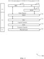
- FIG. 3 illustrates an example of a protocol stack 300 that supports acknowledgment feedback techniques in wireless communications with large propagation delays in accordance with aspects of the present disclosure.
- protocol stack 300 may implement aspects of wireless communications system 100 or 200. Aspects of protocol stack 300 may be implemented by a base station, satellite, and/or a UE, which may be examples of the corresponding transmitting and/or receiving devices described herein.
- L1 layer is the lowest layer and implements various physical layer signal processing functions, and is referred to herein as the physical layer.
- L1 may include the physical sublayer 305 which monitors, controls, or otherwise manages aspects of the wireless transmissions over the wireless medium.
- L2 layer is above the physical sublayer 305 (e.g., above L 1) and is responsible for managing aspects of the wireless link between the UE and network device (or base station) over the physical sublayer 305.
- L2 includes a MAC sublayer 310, a RLC sublayer 315, and a PDCP sublayer 320, which are terminated at the network device on the network side.
- the PDCP sublayer 320 provides multiplexing between different radio bearers and logical channels.
- the PDCP sublayer 320 also provides header compression for upper layer data packets to reduce radio transmission overhead, security by ciphering the data packets, and handover support for UEs between network devices.
- the PDCP sublayer 320 also manages integrity protection (on the transmitter side) and/or verification (on the receiver side), packet expiry timer operations, packet ordering/reordering operations, and the like.
- the RLC sublayer 315 provides segmentation and reassembly of upper layer data packets, retransmission of lost data packets, and reordering of data packets to compensate for out-of-order reception due to HARQ.
- the RLC sublayer 315 passes data to the MAC sublayer 310 as logical channels.
- a logical channel may define what type of information is being transmitted over the air interface (e.g., user traffic, control channels, broadcast information, etc.).
- two or more logical channels may be combined into a logical channel group (LCG).
- the transport channel defines how information is being transmitted over the air interface (e.g., encoding, interleaving, etc.) and the physical channel defines where information is being transmitted over the air interface (e.g., which symbols of the slot, subframe, fame, etc., are carrying the information).
- the radio protocol architecture for the UE and network device is substantially the same for the physical sublayer 305 and the L2 with the exception that there is no header compression function for the control plane.
- the control plane also includes a RRC sublayer 325 in L3.
- the RRC sublayer 325 is responsible for obtaining radio resources (i.e., radio bearers) and for configuring the lower layers using RRC signaling between the network device and the UE.
- protocol stack 300 may also include a service data adaptation protocol (SDAP) sublayer 335 between the IP sublayer 330 and the PDCP sublayer 320.
- SDAP service data adaptation protocol
- the SDAP sublayer 335 may perform functions such as mapping between QoS flow and DRB, marking QoS flow ID in both downlink and uplink packets, and the like.
- a single protocol entity for SDAP sublayer 335 may be configured for each individual PDU session, except for dual-connectivity configuration where two entities can be configured.
- the PDCP sublayer 320 may manage aspects of integrity protection and/or packet ordering for wireless transmissions.
- HARQ feedback for one or more transmissions may be determined at the physical sublayer 305, and may be transmitted using higher layer communications, such as in a MAC sublayer 310 MAC-CE.
- FIGs. 4A and 4B illustrate examples of MAC-CE formats 400 and 450 that support acknowledgment feedback techniques in wireless communications with large propagation delays in accordance with aspects of the present disclosure.
- MAC-CE formats 400 and 450 may be implemented in aspects of wireless communications system 100 or 200.
- MAC-CE format 400 may include MAC-CE feedback data 405 that is provided in a fixed size MAC-CE 400.
- the fixed size MAC-CE 400 in this example provides two bytes of information, although the size may be increased or decreased based on a number of configured HARQ processes at the UE, base station, or satellite.
- a first octet 410 may include a bitmap for a first set of eight HARQ processes H 0 through H 7
- a second octet 415 may include a bitmap for a second set of eight HARQ processes H 8 through H 15 .
- a value of zero (0) in the bitmap may indicate no issue occurred whereas a value of one (1) may indicate that there was problem in the HARQ process.
- the physical layer feedback may be provided in other types of MAC-CEs.
- a downlink channel quality report may be provided for a first X number HARQ process which suffered from failure or X HARQ processes that have a highest number of retransmissions.
- MAC-CE format 450 provides a variable-size MAC-CE that provides MAC-CE feedback data 455 that indicates a HARQ process ID (e.g., a 4 bits ID) and a corresponding number of times the data is attempted to be decoded (x >1 bits).
- a HARQ process ID e.g., a 4 bits ID
- a first octet 460 may include a first HARQ process ID and number of associated retransmissions, as well as one or more initial bits of a second HARQ process ID.
- a second octet 465 may include remaining bits of the second HARQ process ID, a number of associated retransmissions, as well as one or more initial bits of a third HARQ process ID.
- a third octet 470 may include remaining bits of the third HARQ process ID, a number of associated retransmissions.
- a last octet of the MAC-CE feedback data 455, corresponding to the third octet 470 in the example of FIG. 4B may include one or more padding bits, in the event that one or more available bits of the associated octet are unused.
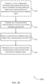
- FIG. 5 illustrates an example of a process flow 500 that supports acknowledgment feedback techniques in wireless communications with large propagation delays in accordance with aspects of the present disclosure.
- process flow 500 may implement aspects of wireless communications system 100 or 200.
- the process flow 500 may illustrate an example of providing physical layer feedback using higher layer communications.
- UE 115-b may be an example of UEs 115 as described with reference to FIGs. 1 and 2 .
- Satellite 120-b may be an example of satellites 120 as described with reference to FIGs. 1 and 2 .
- Satellite 120-b may be an example of a non-terrestrial base station.
- satellite 120-b may instead be a base station 105 in a terrestrial network that is located a relatively large distance from UE 115-b, or the operations described herein may be performed by a combination of the satellite 120-b and a base station.
- Alternative examples of the following may be implemented, where some steps are performed in a different order than described or are not performed at all. In some cases, steps may include additional features not mentioned below, or further steps may be added.
- the satellite 120-b and UE 115-b may establish a connection.
- the connection may be established according to connection establishment techniques such as through transmission of a random access request and associated random access response, and control signaling for RRC connection establishment.
- the satellite 120-b may determine a feedback configuration for the UE 115-b.
- the satellite 120-b may determine that physical layer HARQ feedback is to be disabled. For example, the satellite 120-b may determine that a round trip time associated with communications with the UE 115-b exceeds a value that may provide for efficient physical layer feedback communications (e.g., due to HARQ processes stalling while waiting for HARQ process resolution).
- the satellite 120-b may determine to configure the UE 115-b to provide physical layer feedback using higher layer communications, in accordance with techniques as discussed herein.
- the determination to configure the physical layer feedback for transmission in higher layer communications may be based on one or more conditions, such as discussed with reference to FIG. 2 , identified at the satellite 120-b, or that may be reported by the UE 115-b.
- the satellite 120-b may transmit a configuration message (e.g., via control signaling such as DCI, an RRC message, a SIB, among other examples of control signaling) to the UE 115-b.
- the configuration message may indicate that physical layer feedback reporting is disabled, and may indicate that higher layer communications with the physical layer feedback information are to be provided.
- the satellite 120-b may determine one or more parameters for communication of the higher layer signaling, such as an LCID associated with a MAC-CE that is to be used to communicate the physical layer feedback.
- the UE 115-b may receive the configuration message and disable the physical layer HARQ feedback. In some cases, the UE 115-b may still perform HARQ processes at the physical layer, in accordance with a configured number of HARQ process IDs, but not transmit the physical layer HARQ feedback using physical layer communications.
- the satellite 120-b may transmit one or more downlink communications to the UE 115-b.
- the satellite 120-b may transmit a feedback request to the UE 115-b.
- the UE 115-b may determine that one or more conditions are present that trigger the transmission of physical layer HARQ feedback using higher layer communications. Such conditions that may trigger the higher layer transmission may include one or more conditions such as discussed with respect to FIG. 2 .
- the UE 115-b may determine physical layer HARQ feedback associated with the one or more downlink transmissions from the satellite 120-b.
- the physical layer HARQ feedback may be determined for configured HARQ process IDs, based on whether each downlink transmission has been successfully decoded or not.
- the UE 115-b may format a MAC-CE with the physical layer feedback.
- the MAC-CE may have a format such as discussed with reference to FIGs. 4A and 4B .
- the UE 115-b may transmit the MAC-CE to the satellite 120-b.
- the satellite 120-b may receive the MAC-CE with the physical layer feedback, and determine one of more HARQ process IDs that were unsuccessfully received at the UE 115-b, and determine whether one or more retransmissions are needed for one or more of the downlink transmissions.
- the satellite 120-b may identify the MAC-CE as having physical layer feedback based on a reserved LCID or an extended reserved LCID of the MAC-CE that indicates the feedback information.
- the UE 115-b may optionally, at 560, transmit one or more uplink transmissions to the satellite 120-b.
- the satellite 120-b may determine physical layer feedback for the uplink transmissions and format a MAC-CE with the physical layer HARQ feedback.
- the satellite 120-b may transmit the MAC-CE to the UE 115-b, which may determine whether one or more uplink transmissions are to be retransmitted.
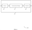
- FIG. 6 shows a block diagram 600 of a device 605 that supports acknowledgment feedback techniques in wireless communications with large propagation delays in accordance with aspects of the present disclosure.
- the device 605 may be an example of aspects of a UE 115 as described herein.
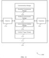
- the device 605 may include a receiver 610, a communications manager 615, and a transmitter 620.
- the device 605 may also include a processor. Each of these components may be in communication with one another (e.g., via one or more buses).
- the receiver 610 may receive information such as packets, user data, or control information associated with various information channels (e.g., control channels, data channels, and information related to acknowledgment feedback techniques in wireless communications with large propagation delays, etc.). Information may be passed on to other components of the device 605.
- the receiver 610 may be an example of aspects of the transceiver 920 described with reference to FIG. 9 .
- the receiver 610 may utilize a single antenna or a set of antennas.
- the communications manager 615 may receive one or more downlink transmissions from a base station via a wireless connection with the base station, determine physical layer feedback for the one or more downlink transmissions, and transmit the physical layer feedback in one or more higher layer communications with the base station.
- the physical layer feedback may be determined at a physical layer of a protocol stack at the UE that is a lower layer than one or more higher layers used to transmit the higher layer communications.
- the communications manager 615 may also receive one or more downlink transmissions from a base station via a wireless connection with the base station, determine physical layer feedback for the one or more downlink transmissions, where the physical layer feedback is determined at a physical layer of a protocol stack of the UE that is a lower layer than one or more higher layers of the protocol stack, identify that one or more conditions associated with the wireless connection indicate that the physical layer feedback is to be provided to the base station, and transmit, responsive to the identifying, the physical layer feedback to the base station.
- the communications manager 615 may be an example of aspects of the communications manager 910 described herein.
- the communications manager 615 may as described herein be implemented to realize one or more potential advantages.
- One implementation may allow the device 605 to provide physical layer feedback (e.g., physical layer HARQ feedback) without stalling a physical layer feedback process due to large propagation delays and round trip times between the device 605 and a transmitting device such as a base station or satellite.
- physical layer feedback may allow for enhanced reliability and reduced latency compared to cases where physical layer feedback may be disabled and higher layer retransmissions used in the event of unsuccessful receipt of one or more transmissions.
- implementations may allow the device 605 to reduce the latency of communications, and increase signaling reliability, throughput, and user experience, while reducing power consumption, among other advantages.
- the communications manager 615 may be implemented in hardware, code (e.g., software or firmware) executed by a processor, or any combination thereof. If implemented in code executed by a processor, the functions of the communications manager 615, or its sub-components may be executed by a general-purpose processor, a DSP, an application-specific integrated circuit (ASIC), a FPGA or other programmable logic device, discrete gate or transistor logic, discrete hardware components, or any combination thereof designed to perform the functions described in the present disclosure.
- code e.g., software or firmware
- ASIC application-specific integrated circuit
- FPGA field-programmable gate
- the communications manager 615 may be physically located at various positions, including being distributed such that portions of functions are implemented at different physical locations by one or more physical components.
- the communications manager 615, or its sub-components may be a separate and distinct component in accordance with various aspects of the present disclosure.
- the communications manager 615, or its sub-components may be combined with one or more other hardware components, including but not limited to an input/output (I/O) component, a transceiver, a network server, another computing device, one or more other components described in the present disclosure, or a combination thereof in accordance with various aspects of the present disclosure.
- I/O input/output
- the transmitter 620 may transmit signals generated by other components of the device 605.
- the transmitter 620 may be collocated with a receiver 610 in a transceiver module.
- the transmitter 620 may be an example of aspects of the transceiver 920 described with reference to FIG. 9 .
- the transmitter 620 may utilize a single antenna or a set of antennas.
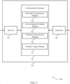
- FIG. 7 shows a block diagram 700 of a device 705 that supports acknowledgment feedback techniques in wireless communications with large propagation delays in accordance with aspects of the present disclosure.
- the device 705 may be an example of aspects of a device 605, or a UE 115 as described herein.
- the device 705 may include a receiver 710, a communications manager 715, and a transmitter 740.
- the device 705 may also include a processor. Each of these components may be in communication with one another (e.g., via one or more buses).
- the receiver 710 may receive information such as packets, user data, or control information associated with various information channels (e.g., control channels, data channels, and information related to acknowledgment feedback techniques in wireless communications with large propagation delays, etc.). Information may be passed on to other components of the device 705.
- the receiver 710 may be an example of aspects of the transceiver 920 described with reference to FIG. 9 .
- the receiver 710 may utilize a single antenna or a set of antennas.
- the communications manager 715 may be an example of aspects of the communications manager 615 as described herein.
- the communications manager 715 may include a downlink communication manager 720, an acknowledgment feedback manager 725, a feedback communication manager 730, and a feedback trigger manager 735.
- the communications manager 715 may be an example of aspects of the communications manager 910 described herein.
- the downlink communication manager 720 may receive one or more downlink transmissions from a base station via a wireless connection with the base station.
- the acknowledgment feedback manager 725 may determine physical layer feedback for the one or more downlink transmissions.
- the feedback communication manager 730 may transmit the physical layer feedback in one or more higher layer communications with the base station.
- the physical layer feedback may be determined at a physical layer of a protocol stack at the UE that is a lower layer than one or more higher layers used to transmit the higher layer communications.
- the downlink communication manager 720 may receive one or more downlink transmissions from a base station via a wireless connection with the base station.
- the acknowledgment feedback manager 725 may determine physical layer feedback for the one or more downlink transmissions, where the physical layer feedback is determined at a physical layer of a protocol stack of the UE that is a lower layer than one or more higher layers of the protocol stack.
- the feedback trigger manager 735 may identify that one or more conditions associated with the wireless connection indicate that the physical layer feedback is to be provided to the base station.
- the feedback communication manager 730 may transmit, responsive to the identifying, the physical layer feedback to the base station.
- the transmitter 740 may transmit signals generated by other components of the device 705.
- the transmitter 740 may be collocated with a receiver 710 in a transceiver module.
- the transmitter 740 may be an example of aspects of the transceiver 920 described with reference to FIG. 9 .
- the transmitter 740 may utilize a single antenna or a set of antennas.
- FIG. 8 shows a block diagram 800 of a communications manager 805 that supports acknowledgment feedback techniques in wireless communications with large propagation delays in accordance with aspects of the present disclosure.
- the communications manager 805 may be an example of aspects of a communications manager 615, a communications manager 715, or a communications manager 910 described herein.
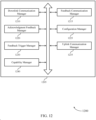
- the communications manager 805 may include a downlink communication manager 810, an acknowledgment feedback manager 815, a feedback communication manager 820, a configuration manager 825, a feedback trigger manager 830, an uplink communication manager 835, and a capability manager 840. Each of these modules may communicate, directly or indirectly, with one another (e.g., via one or more buses).
- the downlink communication manager 810 may receive one or more downlink transmissions from a base station via a wireless connection with the base station.
- the acknowledgment feedback manager 815 may determine physical layer feedback for the one or more downlink transmissions. In some examples, the acknowledgment feedback manager 815 may determine physical layer feedback for the one or more downlink transmissions, where the physical layer feedback is determined at a physical layer of a protocol stack of the UE that is a lower layer than one or more higher layers of the protocol stack. In some examples, the acknowledgment feedback manager 815 may receive, from the base station via higher layer signaling, one or more physical layer feedback reports associated with the one or more uplink communications. In some examples, the acknowledgment feedback manager 815 may retransmit one or more uplink communications based on the one or more physical layer feedback reports.
- the feedback communication manager 820 may transmit the physical layer feedback in one or more higher layer communications with the base station, where the physical layer feedback is determined at a physical layer of a protocol stack at the UE that is a lower layer than one or more higher layers used to transmit the higher layer communications. In some examples, the feedback communication manager 820 may transmit, responsive to the identifying, the physical layer feedback to the base station. In some examples, the feedback communication manager 820 may transmit a MAC-CE that indicates feedback for one or more physical layer acknowledgment feedback processes.
- the feedback communication manager 820 may receive, subsequent to the transmitting the physical layer feedback in the one or more higher layer communications, a resource grant for retransmission of the physical layer feedback. In some examples, the feedback communication manager 820 may retransmit the physical layer feedback in the one or more higher layer communications based on the resource grant.
- the MAC-CE is identified by a reserved logical channel identification (LCID) or new extended LCID that is associated with acknowledgment feedback for the UE.
- the higher layer communications include one or more fixed size data or information transmissions for reporting a predetermined number of physical layer acknowledgment feedback processes to the base station.
- the higher layer communications include a channel quality report associated with a number of feedback processes having a negative acknowledgment feedback status.
- the higher layer communications include one or more variable sized data or information transmissions that each provide an identification of one or more feedback processes.
- the higher layer communications further include one or more of a feedback process identification and a number of times that data associated with the feedback process identification was attempted to be decoded at the UE.
- a first MAC-CE format is configured at the UE for transmission of the physical layer feedback for the one or more downlink transmissions
- a second MAC-CE format is configured at the UE for reception of the one or more physical layer feedback reports associated with the one or more uplink communications.
- the feedback trigger manager 830 may identify that one or more conditions associated with the wireless connection indicate that the physical layer feedback is to be provided to the base station. In some examples, the feedback trigger manager 830 may determine to transmit the physical layer feedback in the one or more higher layer communications based on an indication associated with communications between the UE and the base station. In some examples, the feedback trigger manager 830 may receive an indication from the physical layer that one or more of the downlink transmissions were unsuccessfully decoded. In some examples, the feedback trigger manager 830 may determine that a number of feedback processes for which decoding of an associated downlink transmission is unsuccessful exceeds a threshold number. In some examples, the feedback trigger manager 830 may receive a synchronization error indication from the physical layer.
- the feedback trigger manager 830 may determine that a timer associated with physical layer synchronization has expired. In some examples, the feedback trigger manager 830 may determine that a periodic physical layer feedback report is to be transmitted to the base station. In some cases, a periodic reporting interval is configured by the base station having a periodicity that is based on a propagation delay between the UE and the base station. In some examples, the feedback trigger manager 830 may receive a request from the base station to transmit the physical layer feedback.
- the configuration manager 825 may receive, from the base station prior to the receiving the one or more downlink transmissions, configuration information that disables the physical layer feedback reports and that enables the higher layer communications for transmission of the physical layer feedback.
- the signaling that indicates higher layer communications are to be used for physical layer feedback is received in broadcast information from the base station, in RRC signaling from the base station, or combinations thereof.
- the uplink communication manager 835 may transmit one or more uplink communications to the base station.
- the capability manager 840 may transmit, to the base station, a capability message that indicates the UE is capable to communicate physical layer feedback in one or more higher layer communications with the base station.
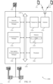
- FIG. 9 shows a diagram of a system 900 including a device 905 that supports acknowledgment feedback techniques in wireless communications with large propagation delays in accordance with aspects of the present disclosure.
- the device 905 may be an example of or include the components of device 605, device 705, or a UE 115 as described herein.
- the device 905 may include components for bi-directional voice and data communications including components for transmitting and receiving communications, including a communications manager 910, an I/O controller 915, a transceiver 920, an antenna 925, memory 930, and a processor 940. These components may be in electronic communication via one or more buses (e.g., bus 945).
- buses e.g., bus 945
- the communications manager 910 may receive one or more downlink transmissions from a base station via a wireless connection with the base station, determine physical layer feedback for the one or more downlink transmissions, and transmit the physical layer feedback in one or more higher layer communications with the base station.
- the physical layer feedback may be determined at a physical layer of a protocol stack at the UE that is a lower layer than one or more higher layers used to transmit the higher layer communications.
- the communications manager 910 may also receive one or more downlink transmissions from a base station via a wireless connection with the base station, determine physical layer feedback for the one or more downlink transmissions, where the physical layer feedback is determined at a physical layer of a protocol stack of the UE that is a lower layer than one or more higher layers of the protocol stack, identify that one or more conditions associated with the wireless connection indicate that the physical layer feedback is to be provided to the base station, and transmit, responsive to the identifying, the physical layer feedback to the base station.
- the communications manager 910 may as described herein be implemented to realize one or more potential advantages.
- One implementation may allow the device 905 to provide physical layer feedback (e.g., physical layer HARQ feedback) without stalling a physical layer feedback process due to large propagation delays and round trip times between the device 905 and a transmitting device such as a base station or satellite.
- physical layer feedback may allow for enhanced reliability and reduced latency compared to cases where physical layer feedback may be disabled and higher layer retransmissions used in the event of unsuccessful receipt of one or more transmissions.
- implementations may allow the device 905 to reduce the latency of communications, and increase signaling reliability, throughput, and user experience, while reducing power consumption, among other advantages.
- the I/O controller 915 may manage input and output signals for the device 905.
- the I/O controller 915 may also manage peripherals not integrated into the device 905.
- the I/O controller 915 may represent a physical connection or port to an external peripheral.
- the I/O controller 915 may utilize an operating system such as iOS ® , ANDROID ® , MS-DOS ® , MS-WINDOWS ® , OS/2 ® , UNIX ® , LINUX ® , or another known operating system.
- the I/O controller 915 may represent or interact with a modem, a keyboard, a mouse, a touchscreen, or a similar device.
- the I/O controller 915 may be implemented as part of a processor.
- a user may interact with the device 905 via the I/O controller 915 or via hardware components controlled by the I/O controller 915.
- the transceiver 920 may communicate bi-directionally, via one or more antennas, wired, or wireless links as described above.
- the transceiver 920 may represent a wireless transceiver and may communicate bi-directionally with another wireless transceiver.
- the transceiver 920 may also include a modem to modulate the packets and provide the modulated packets to the antennas for transmission, and to demodulate packets received from the antennas.
- the wireless device may include a single antenna 925. However, in some cases the device may have more than one antenna 925, which may be capable of concurrently transmitting or receiving multiple wireless transmissions.
- the memory 930 may include RAM and ROM.
- the memory 930 may store computer-readable, computer-executable code 935 including instructions that, when executed, cause the processor to perform various functions described herein.
- the memory 930 may contain, among other things, a BIOS which may control basic hardware or software operation such as the interaction with peripheral components or devices.
- the processor 940 may include an intelligent hardware device, (e.g., a general-purpose processor, a DSP, a CPU, a microcontroller, an ASIC, an FPGA, a programmable logic device, a discrete gate or transistor logic component, a discrete hardware component, or any combination thereof).
- the processor 940 may be configured to operate a memory array using a memory controller.
- a memory controller may be integrated into the processor 940.
- the processor 940 may be configured to execute computer-readable instructions stored in a memory (e.g., the memory 930) to cause the device 905 to perform various functions (e.g., functions or tasks supporting acknowledgment feedback techniques in wireless communications with large propagation delays).
- the code 935 may include instructions to implement aspects of the present disclosure, including instructions to support wireless communications.
- the code 935 may be stored in a non-transitory computer-readable medium such as system memory or other type of memory. In some cases, the code 935 may not be directly executable by the processor 940 but may cause a computer (e.g., when compiled and executed) to perform functions described herein.
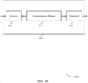
- FIG. 10 shows a block diagram 1000 of a device 1005 that supports acknowledgment feedback techniques in wireless communications with large propagation delays in accordance with aspects of the present disclosure.
- the device 1005 may be an example of aspects of a base station 105 as described herein.
- the device 1005 may include a receiver 1010, a communications manager 1015, and a transmitter 1020.
- the device 1005 may also include a processor. Each of these components may be in communication with one another (e.g., via one or more buses).
- the receiver 1010 may receive information such as packets, user data, or control information associated with various information channels (e.g., control channels, data channels, and information related to acknowledgment feedback techniques in wireless communications with large propagation delays, etc.). Information may be passed on to other components of the device 1005.
- the receiver 1010 may be an example of aspects of the transceiver 1320 described with reference to FIG. 13 .
- the receiver 1010 may utilize a single antenna or a set of antennas.
- the communications manager 1015 may transmit one or more downlink communications to a UE via a wireless connection with the UE, receive a physical layer feedback report in a higher layer communication from the UE, where the physical layer feedback may be generated by a physical layer of a protocol stack at the UE that is a lower layer than one or more higher layers of the protocol stack, and retransmit one or more of the downlink communication to the UE based on the physical layer feedback report.
- the communications manager 1015 may also transmit one or more downlink transmissions to a UE via a wireless connection with the UE, identify that one or more conditions associated with the wireless connection indicate that physical layer feedback is to be provided to the base station, and receive, responsive to the identifying, the physical layer feedback from the UE, where the physical layer feedback is generated by a physical layer of a protocol stack of the UE that is a lower layer than one or more higher layers of the protocol stack of the UE.
- the communications manager 1015 may be an example of aspects of the communications manager 1310 described herein.
- the communications manager 1015 may be implemented in hardware, code (e.g., software or firmware) executed by a processor, or any combination thereof. If implemented in code executed by a processor, the functions of the communications manager 1015, or its sub-components may be executed by a general-purpose processor, a DSP, an application-specific integrated circuit (ASIC), a FPGA or other programmable logic device, discrete gate or transistor logic, discrete hardware components, or any combination thereof designed to perform the functions described in the present disclosure.
- code e.g., software or firmware
- ASIC application-specific integrated circuit
- FPGA field-programmable gate
- the communications manager 1015 may be physically located at various positions, including being distributed such that portions of functions are implemented at different physical locations by one or more physical components.
- the communications manager 1015, or its sub-components may be a separate and distinct component in accordance with various aspects of the present disclosure.
- the communications manager 1015, or its sub-components may be combined with one or more other hardware components, including but not limited to an input/output (I/O) component, a transceiver, a network server, another computing device, one or more other components described in the present disclosure, or a combination thereof in accordance with various aspects of the present disclosure.
- I/O input/output
- the transmitter 1020 may transmit signals generated by other components of the device 1005.
- the transmitter 1020 may be collocated with a receiver 1010 in a transceiver module.
- the transmitter 1020 may be an example of aspects of the transceiver 1320 described with reference to FIG. 13 .
- the transmitter 1020 may utilize a single antenna or a set of antennas.
- FIG. 11 shows a block diagram 1100 of a device 1105 that supports acknowledgment feedback techniques in wireless communications with large propagation delays in accordance with aspects of the present disclosure.
- the device 1105 may be an example of aspects of a device 1005, or a base station 105 as described herein.
- the device 1105 may include a receiver 1110, a communications manager 1115, and a transmitter 1140.
- the device 1105 may also include a processor. Each of these components may be in communication with one another (e.g., via one or more buses).
- the receiver 1110 may receive information such as packets, user data, or control information associated with various information channels (e.g., control channels, data channels, and information related to acknowledgment feedback techniques in wireless communications with large propagation delays, etc.). Information may be passed on to other components of the device 1105.
- the receiver 1110 may be an example of aspects of the transceiver 1320 described with reference to FIG. 13 .
- the receiver 1110 may utilize a single antenna or a set of antennas.
- the communications manager 1115 may be an example of aspects of the communications manager 1015 as described herein.
- the communications manager 1115 may include a downlink communication manager 1120, a feedback communication manager 1125, an acknowledgment feedback manager 1130, and a feedback trigger manager 1135.
- the communications manager 1115 may be an example of aspects of the communications manager 1310 described herein.
- the downlink communication manager 1120 may transmit one or more downlink communications to a UE via a wireless connection with the UE.
- the feedback communication manager 1125 may receive a physical layer feedback report in a higher layer communication from the UE, where the physical layer feedback is generated by a physical layer of a protocol stack at the UE that is a lower layer than one or more higher layers of the protocol stack.
- the acknowledgment feedback manager 1130 may retransmit one or more of the downlink communication to the UE based on the physical layer feedback report.
- the downlink communication manager 1120 may transmit one or more downlink transmissions to a UE via a wireless connection with the UE.
- the feedback trigger manager 1135 may identify that one or more conditions associated with the wireless connection indicate that physical layer feedback is to be provided to the base station.
- the feedback communication manager 1125 may receive, responsive to the identifying, the physical layer feedback from the UE, where the physical layer feedback is generated by a physical layer of a protocol stack of the UE that is a lower layer than one or more higher layers of the protocol stack of the UE.
- the transmitter 1140 may transmit signals generated by other components of the device 1105.
- the transmitter 1140 may be collocated with a receiver 1110 in a transceiver module.
- the transmitter 1140 may be an example of aspects of the transceiver 1320 described with reference to FIG. 13 .
- the transmitter 1140 may utilize a single antenna or a set of antennas.
- FIG. 12 shows a block diagram 1200 of a communications manager 1205 that supports acknowledgment feedback techniques in wireless communications with large propagation delays in accordance with aspects of the present disclosure.
- the communications manager 1205 may be an example of aspects of a communications manager 1015, a communications manager 1115, or a communications manager 1310 described herein.
- the communications manager 1205 may include a downlink communication manager 1210, a feedback communication manager 1215, an acknowledgment feedback manager 1220, a configuration manager 1225, a feedback trigger manager 1230, an uplink communication manager 1235, and a capability manager 1240. Each of these modules may communicate, directly or indirectly, with one another (e.g., via one or more buses).
- the downlink communication manager 1210 may transmit one or more downlink communications to a UE via a wireless connection with the UE.
- the feedback communication manager 1215 may receive a physical layer feedback report in a higher layer communication from the UE, where the physical layer feedback is generated by a physical layer of a protocol stack at the UE that is a lower layer than one or more higher layers of the protocol stack. In some examples, the feedback communication manager 1215 may transmit, to the UE via higher layer signaling, one or more physical layer feedback reports associated with the one or more uplink communications.
- the higher layer communication from the UE is a MAC layer communication that includes a MAC-CE that indicates feedback for one or more physical layer acknowledgment feedback processes of the UE.
- the MAC-CE includes a reserved logical channel identification (LCID) or a new extended LCID that is associated with acknowledgment feedback for the UE.
- LCID reserved logical channel identification
- the higher layer communication includes one or more fixed size data or information transmissions for reporting a predetermined number of physical layer feedback processes of the UE. In some cases, the higher layer communication includes a channel quality report associated with a number of feedback processes having a negative acknowledgment feedback status. In some cases, the higher layer communication includes one or more variable sized data or information transmissions that each provide an identification of one or more feedback processes at the UE. In some cases, the higher layer communication further includes one or more of a feedback process identification and a number of times that data associated with the feedback process identification was attempted to be decoded at the UE.
- a first MAC-CE format is configured at the UE for transmission of the physical layer feedback report for the one or more downlink transmissions
- a second MAC-CE format is configured at the UE for reception of the one or more physical layer feedback reports associated with the one or more uplink communications.
- the acknowledgment feedback manager 1220 may retransmit one or more of the downlink communication to the UE based on the physical layer feedback report.
- the acknowledgment feedback manager 1220 may determine physical layer feedback associated with the one or more uplink communications.
- the acknowledgment feedback manager 1220 may transmit, responsive to a failure to decode the physical layer acknowledgment feedback report in the higher layer communication, a resource grant for retransmission of the physical layer feedback.
- the acknowledgment feedback manager 1220 may monitor for a retransmission of the physical layer feedback report in the one or more higher layer communications based on the resource grant.
- the feedback trigger manager 1230 may identify that one or more conditions associated with the wireless connection indicate that physical layer feedback is to be provided to the base station. In some examples, the feedback trigger manager 1230 may configure the UE to transmit the physical layer feedback report in the higher layer communication based on one or more of a request to the UE to transmit the physical layer feedback, a physical layer indication that one or more of the downlink transmissions were unsuccessfully decoded, a physical layer indication that decoding failed for one or more feedback process identifications, or that a number of unsuccessful decoding attempts of one or more of the downlink transmissions exceeds a threshold value, a number of feedback processes for which decoding of an associated downlink transmission is unsuccessful exceeds a threshold number, a synchronization error at the physical layer of the UE, an expiration of a timer associated with physical layer synchronization, a timing associated with a periodic physical layer feedback report, or any combinations thereof.
- the configuration manager 1225 may transmit, to the UE, configuration information that disables physical layer reports of feedback and that enables the higher layer communications for transmission of the physical layer feedback report.
- the configuration manager 1225 may disable physical layer reports of the physical layer feedback prior to the transmitting the one or more downlink transmissions to the UE.
- the configuration manager 1225 may configure the UE with the timing for periodic physical layer feedback reports based on a propagation delay between the UE and the base station.
- the signaling that indicates the higher layer communication is to be used for physical layer feedback is transmitted in broadcast information from the base station, in RRC signaling from the base station, or combinations thereof.
- the uplink communication manager 1235 may receive one or more uplink communications from the UE.
- the capability manager 1240 may receive, from the UE, a capability message that indicates the UE is capable to communicate physical layer feedback in one or more higher layer communications with the base station.
- FIG. 13 shows a diagram of a system 1300 including a device 1305 that supports acknowledgment feedback techniques in wireless communications with large propagation delays in accordance with aspects of the present disclosure.
- the device 1305 may be an example of or include the components of device 1005, device 1105, or a base station 105 as described herein.
- the device 1305 may include components for bi-directional voice and data communications including components for transmitting and receiving communications, including a communications manager 1310, a network communications manager 1315, a transceiver 1320, an antenna 1325, memory 1330, a processor 1340, and an inter-station communications manager 1345. These components may be in electronic communication via one or more buses (e.g., bus 1350).
- buses e.g., bus 1350
- the communications manager 1310 may transmit one or more downlink communications to a UE via a wireless connection with the UE, receive a physical layer feedback report in a higher layer communication from the UE, where the physical layer feedback is generated by a physical layer of a protocol stack at the UE that is a lower layer than one or more higher layers of the protocol stack, and retransmit one or more of the downlink communication to the UE based on the physical layer feedback report.
- the communications manager 1310 may also transmit one or more downlink transmissions to a UE via a wireless connection with the UE, identify that one or more conditions associated with the wireless connection indicate that physical layer feedback is to be provided to the base station, and receive, responsive to the identifying, the physical layer feedback from the UE, where the physical layer feedback is generated by a physical layer of a protocol stack of the UE that is a lower layer than one or more higher layers of the protocol stack of the UE.
- the network communications manager 1315 may manage communications with the core network (e.g., via one or more wired backhaul links). For example, the network communications manager 1315 may manage the transfer of data communications for client devices, such as one or more UEs 115.
- the transceiver 1320 may communicate bi-directionally, via one or more antennas, wired, or wireless links as described above.
- the transceiver 1320 may represent a wireless transceiver and may communicate bi-directionally with another wireless transceiver.
- the transceiver 1320 may also include a modem to modulate the packets and provide the modulated packets to the antennas for transmission, and to demodulate packets received from the antennas.
- the wireless device may include a single antenna 1325. However, in some cases the device may have more than one antenna 1325, which may be capable of concurrently transmitting or receiving multiple wireless transmissions.
- the memory 1330 may include RAM, ROM, or a combination thereof.
- the memory 1330 may store computer-readable code 1335 including instructions that, when executed by a processor (e.g., the processor 1340) cause the device to perform various functions described herein.
- a processor e.g., the processor 1340
- the memory 1330 may contain, among other things, a BIOS which may control basic hardware or software operation such as the interaction with peripheral components or devices.
- the processor 1340 may include an intelligent hardware device, (e.g., a general-purpose processor, a DSP, a CPU, a microcontroller, an ASIC, an FPGA, a programmable logic device, a discrete gate or transistor logic component, a discrete hardware component, or any combination thereof).
- the processor 1340 may be configured to operate a memory array using a memory controller.
- a memory controller may be integrated into processor 1340.
- the processor 1340 may be configured to execute computer-readable instructions stored in a memory (e.g., the memory 1330) to cause the device 1305 to perform various functions (e.g., functions or tasks supporting acknowledgment feedback techniques in wireless communications with large propagation delays).
- the inter-station communications manager 1345 may manage communications with other base station 105, and may include a controller or scheduler for controlling communications with UEs 115 in cooperation with other base stations 105. For example, the inter-station communications manager 1345 may coordinate scheduling for transmissions to UEs 115 for various interference mitigation techniques such as beamforming or joint transmission. In some examples, the inter-station communications manager 1345 may provide an X2 interface within an LTE/LTE-A wireless communication network technology to provide communication between base stations 105.
- the code 1335 may include instructions to implement aspects of the present disclosure, including instructions to support wireless communications.
- the code 1335 may be stored in a non-transitory computer-readable medium such as system memory or other type of memory. In some cases, the code 1335 may not be directly executable by the processor 1340 but may cause a computer (e.g., when compiled and executed) to perform functions described herein.
- FIG. 14 shows a flowchart illustrating a method 1400 that supports acknowledgment feedback techniques in wireless communications with large propagation delays in accordance with aspects of the present disclosure.
- the operations of method 1400 may be implemented by a UE 115 or its components as described herein.
- the operations of method 1400 may be performed by a communications manager as described with reference to FIGs. 6 through 9 .
- a UE may execute a set of instructions to control the functional elements of the UE to perform the functions described below. Additionally or alternatively, a UE may perform aspects of the functions described below using special-purpose hardware.
- the UE may receive configuration information that disables physical layer feedback reports and that enables the higher layer communications for transmission of the physical layer feedback.
- the operations of 1405 may be performed according to the methods described herein. In some examples, aspects of the operations of 1405 may be performed by a configuration manager as described with reference to FIGs. 6 through 9 .
- the UE may receive one or more downlink transmissions from a base station via a wireless connection with the base station.
- the operations of 1410 may be performed according to the methods described herein. In some examples, aspects of the operations of 1410 may be performed by a downlink communication manager as described with reference to FIGs. 6 through 9 .
- the UE may determine physical layer feedback for the one or more downlink transmissions.
- the operations of 1415 may be performed according to the methods described herein. In some examples, aspects of the operations of 1415 may be performed by an acknowledgment feedback manager as described with reference to FIGs. 6 through 9 .
- the UE may transmit the physical layer feedback in one or more higher layer communications with the base station.
- the physical layer feedback is determined at a physical layer of a protocol stack at the UE that is a lower layer than one or more higher layers used to transmit the higher layer communications.
- the operations of 1420 may be performed according to the methods described herein. In some examples, aspects of the operations of 1420 may be performed by a feedback communication manager as described with reference to FIGs. 6 through 9 .
- FIG. 15 shows a flowchart illustrating a method 1500 that supports acknowledgment feedback techniques in wireless communications with large propagation delays in accordance with aspects of the present disclosure.
- the operations of method 1500 may be implemented by a UE 115 or its components as described herein.
- the operations of method 1500 may be performed by a communications manager as described with reference to FIGs. 6 through 9 .
- a UE may execute a set of instructions to control the functional elements of the UE to perform the functions described below. Additionally or alternatively, a UE may perform aspects of the functions described below using special-purpose hardware.
- the UE may transmit, to a base station, a capability message that indicates the UE is capable to communicate physical layer feedback in one or more higher layer communications with the base station.
- the operations of 1505 may be performed according to the methods described herein. In some examples, aspects of the operations of 1505 may be performed by a capability manager as described with reference to FIGs. 6 through 9 .
- the UE may receive, from the base station, signaling that indicates higher layer communications are to be used for physical layer feedback.
- the operations of 1510 may be performed according to the methods described herein. In some examples, aspects of the operations of 1510 may be performed by a configuration manager as described with reference to FIGs. 6 through 9 .
- the UE may receive one or more downlink transmissions from the base station via a wireless connection with the base station.
- the operations of 1515 may be performed according to the methods described herein. In some examples, aspects of the operations of 1515 may be performed by a downlink communication manager as described with reference to FIGs. 6 through 9 .
- the UE may determine physical layer feedback for the one or more downlink transmissions.
- the operations of 1520 may be performed according to the methods described herein. In some examples, aspects of the operations of 1520 may be performed by an acknowledgment feedback manager as described with reference to FIGs. 6 through 9 .
- the UE may transmit the physical layer feedback in one or more higher layer communications with the base station, where the physical layer feedback is determined at a physical layer of a protocol stack at the UE that is a lower layer than one or more higher layers used to transmit the higher layer communications.
- the operations of 1525 may be performed according to the methods described herein. In some examples, aspects of the operations of 1525 may be performed by a feedback communication manager as described with reference to FIGs. 6 through 9 .
- the UE may transmit one or more uplink communications to the base station.
- the operations of 1530 may be performed according to the methods described herein. In some examples, aspects of the operations of 1530 may be performed by an uplink communication manager as described with reference to FIGs. 6 through 9 .
- the UE may receive, from the base station via higher layer signaling, one or more physical layer feedback reports associated with the one or more uplink communications.
- the operations of 1535 may be performed according to the methods described herein. In some examples, aspects of the operations of 1535 may be performed by an acknowledgment feedback manager as described with reference to FIGs. 6 through 9 .
- the UE may retransmit one or more uplink communications based on the one or more physical layer feedback reports.
- the operations of 1540 may be performed according to the methods described herein. In some examples, aspects of the operations of 1540 may be performed by an acknowledgment feedback manager as described with reference to FIGs. 6 through 9 .
- FIG. 16 shows a flowchart illustrating a method 1600 that supports acknowledgment feedback techniques in wireless communications with large propagation delays in accordance with aspects of the present disclosure.
- the operations of method 1600 may be implemented by a UE 115 or its components as described herein.
- the operations of method 1600 may be performed by a communications manager as described with reference to FIGs. 6 through 9 .
- a UE may execute a set of instructions to control the functional elements of the UE to perform the functions described below. Additionally or alternatively, a UE may perform aspects of the functions described below using special-purpose hardware.
- the UE may receive one or more downlink transmissions from a base station via a wireless connection with the base station.
- the operations of 1605 may be performed according to the methods described herein. In some examples, aspects of the operations of 1605 may be performed by a downlink communication manager as described with reference to FIGs. 6 through 9 .
- the UE may determine physical layer feedback for the one or more downlink transmissions.
- the operations of 1610 may be performed according to the methods described herein. In some examples, aspects of the operations of 1610 may be performed by an acknowledgment feedback manager as described with reference to FIGs. 6 through 9 .
- the UE may transmit the physical layer feedback in one or more higher layer communications with the base station, where the physical layer feedback is determined at a physical layer of a protocol stack at the UE that is a lower layer than one or more higher layers used to transmit the higher layer communications.
- the operations of 1615 may be performed according to the methods described herein. In some examples, aspects of the operations of 1615 may be performed by a feedback communication manager as described with reference to FIGs. 6 through 9 .
- the UE may receive, subsequent to the transmitting the physical layer feedback in the one or more higher layer communications, a resource grant for retransmission of the physical layer feedback.
- the operations of 1620 may be performed according to the methods described herein. In some examples, aspects of the operations of 1620 may be performed by a feedback communication manager as described with reference to FIGs. 6 through 9 .
- the UE may retransmit the physical layer feedback in the one or more higher layer communications based on the resource grant.
- the operations of 1625 may be performed according to the methods described herein. In some examples, aspects of the operations of 1625 may be performed by a feedback communication manager as described with reference to FIGs. 6 through 9 .
- FIG. 17 shows a flowchart illustrating a method 1700 that supports acknowledgment feedback techniques in wireless communications with large propagation delays in accordance with aspects of the present disclosure.
- the operations of method 1700 may be implemented by a UE 115 or its components as described herein.
- the operations of method 1700 may be performed by a communications manager as described with reference to FIGs. 6 through 9 .
- a UE may execute a set of instructions to control the functional elements of the UE to perform the functions described below. Additionally or alternatively, a UE may perform aspects of the functions described below using special-purpose hardware.
- the UE may receive one or more downlink transmissions from a base station via a wireless connection with the base station.
- the operations of 1705 may be performed according to the methods described herein. In some examples, aspects of the operations of 1705 may be performed by a downlink communication manager as described with reference to FIGs. 6 through 9 .
- the UE may determine physical layer feedback for the one or more downlink transmissions, where the physical layer feedback is determined at a physical layer of a protocol stack of the UE that is a lower layer than one or more higher layers of the protocol stack.
- the operations of 1710 may be performed according to the methods described herein. In some examples, aspects of the operations of 1710 may be performed by an acknowledgment feedback manager as described with reference to FIGs. 6 through 9 .
- the UE may identify that one or more conditions associated with the wireless connection indicate that the physical layer feedback is to be provided to the base station.
- the operations of 1715 may be performed according to the methods described herein. In some examples, aspects of the operations of 1715 may be performed by a feedback trigger manager as described with reference to FIGs. 6 through 9 .
- the UE may transmit, responsive to the identifying, the physical layer feedback to the base station.
- the operations of 1720 may be performed according to the methods described herein. In some examples, aspects of the operations of 1720 may be performed by a feedback communication manager as described with reference to FIGs. 6 through 9 .
- FIG. 18 shows a flowchart illustrating a method 1800 that supports acknowledgment feedback techniques in wireless communications with large propagation delays in accordance with aspects of the present disclosure.
- the operations of method 1800 may be implemented by a UE 115 or its components as described herein.
- the operations of method 1800 may be performed by a communications manager as described with reference to FIGs. 6 through 9 .
- a UE may execute a set of instructions to control the functional elements of the UE to perform the functions described below. Additionally or alternatively, a UE may perform aspects of the functions described below using special-purpose hardware.
- the UE may disable, prior to receiving one or more downlink transmissions, physical layer reports of feedback for a wireless connection between the UE and a base station.
- the operations of 1805 may be performed according to the methods described herein. In some examples, aspects of the operations of 1805 may be performed by a configuration manager as described with reference to FIGs. 6 through 9 .
- the UE may receive one or more downlink transmissions from a base station via a wireless connection with the base station.
- the operations of 1810 may be performed according to the methods described herein. In some examples, aspects of the operations of 1810 may be performed by a downlink communication manager as described with reference to FIGs. 6 through 9 .
- the UE may determine physical layer feedback for the one or more downlink transmissions, where the physical layer feedback is determined at a physical layer of a protocol stack of the UE that is a lower layer than one or more higher layers of the protocol stack.
- the operations of 1815 may be performed according to the methods described herein. In some examples, aspects of the operations of 1815 may be performed by an acknowledgment feedback manager as described with reference to FIGs. 6 through 9 .
- the UE may identify that one or more conditions associated with the wireless connection indicate that the physical layer feedback is to be provided to the base station.
- the operations of 1820 may be performed according to the methods described herein. In some examples, aspects of the operations of 1820 may be performed by a feedback trigger manager as described with reference to FIGs. 6 through 9 .
- the UE may transmit the physical layer feedback in a higher layer communication with the base station.
- the operations of 1825 may be performed according to the methods described herein. In some examples, aspects of the operations of 1825 may be performed by a feedback communication manager as described with reference to FIGs. 6 through 9 .
- FIG. 19 shows a flowchart illustrating a method 1900 that supports acknowledgment feedback techniques in wireless communications with large propagation delays in accordance with aspects of the present disclosure.
- the operations of method 1900 may be implemented by a UE 115 or its components as described herein.
- the operations of method 1900 may be performed by a communications manager as described with reference to FIGs. 6 through 9 .
- a UE may execute a set of instructions to control the functional elements of the UE to perform the functions described below. Additionally or alternatively, a UE may perform aspects of the functions described below using special-purpose hardware.
- the UE may receive one or more downlink transmissions from a base station via a wireless connection with the base station.
- the operations of 1905 may be performed according to the methods described herein. In some examples, aspects of the operations of 1905 may be performed by a downlink communication manager as described with reference to FIGs. 6 through 9 .
- the UE may determine physical layer feedback for the one or more downlink transmissions, where the physical layer feedback is determined at a physical layer of a protocol stack of the UE that is a lower layer than one or more higher layers of the protocol stack.
- the operations of 1910 may be performed according to the methods described herein. In some examples, aspects of the operations of 1910 may be performed by an acknowledgment feedback manager as described with reference to FIGs. 6 through 9 .
- the UE may identify that one or more conditions associated with the wireless connection indicate that the physical layer feedback is to be provided to the base station.
- the operations of 1915 may be performed according to the methods described herein. In some examples, aspects of the operations of 1915 may be performed by a feedback trigger manager as described with reference to FIGs. 6 through 9 .
- the UE may transmit, responsive to the identifying, the physical layer feedback to the base station.
- the operations of 1920 may be performed according to the methods described herein. In some examples, aspects of the operations of 1920 may be performed by a feedback communication manager as described with reference to FIGs. 6 through 9 .
- the UE may transmit one or more uplink communications to the base station.
- the operations of 1925 may be performed according to the methods described herein. In some examples, aspects of the operations of 1925 may be performed by an uplink communication manager as described with reference to FIGs. 6 through 9 .
- the UE may receive, from the base station via higher layer signaling, one or more physical layer feedback reports associated with the one or more uplink communications.
- the operations of 1930 may be performed according to the methods described herein. In some examples, aspects of the operations of 1930 may be performed by an acknowledgment feedback manager as described with reference to FIGs. 6 through 9 .
- the UE may retransmit one or more uplink communications based on the one or more physical layer feedback reports.
- the operations of 1935 may be performed according to the methods described herein. In some examples, aspects of the operations of 1935 may be performed by an acknowledgment feedback manager as described with reference to FIGs. 6 through 9 .
- FIG. 20 shows a flowchart illustrating a method 2000 that supports acknowledgment feedback techniques in wireless communications with large propagation delays in accordance with aspects of the present disclosure.
- the operations of method 2000 may be implemented by a base station 105 or its components as described herein.
- the operations of method 2000 may be performed by a communications manager as described with reference to FIGs. 10 through 13 .
- a base station may execute a set of instructions to control the functional elements of the base station to perform the functions described below. Additionally or alternatively, a base station may perform aspects of the functions described below using special-purpose hardware.
- the base station may transmit, to a UE, configuration information that disables physical layer reports of feedback and that enables the higher layer communications for transmission of the physical layer feedback report.
- the operations of 2005 may be performed according to the methods described herein. In some examples, aspects of the operations of 2005 may be performed by a configuration manager as described with reference to FIGs. 10 through 13 .
- the base station may transmit one or more downlink communications to a UE via a wireless connection with the UE.
- the operations of 2010 may be performed according to the methods described herein. In some examples, aspects of the operations of 2010 may be performed by a downlink communication manager as described with reference to FIGs. 10 through 13 .
- the base station may receive a physical layer feedback report in a higher layer communication from the UE.
- the physical layer feedback is generated by a physical layer of a protocol stack at the UE that is a lower layer than one or more higher layers of the protocol stack.
- the operations of 2015 may be performed according to the methods described herein. In some examples, aspects of the operations of 2015 may be performed by a feedback communication manager as described with reference to FIGs. 10 through 13 .
- the base station may retransmit one or more of the downlink communication to the UE based on the physical layer feedback report.
- the operations of 2020 may be performed according to the methods described herein. In some examples, aspects of the operations of 2020 may be performed by an acknowledgment feedback manager as described with reference to FIGs. 10 through 13 .
- FIG. 21 shows a flowchart illustrating a method 2100 that supports acknowledgment feedback techniques in wireless communications with large propagation delays in accordance with aspects of the present disclosure.
- the operations of method 2100 may be implemented by a base station 105 or its components as described herein.
- the operations of method 2100 may be performed by a communications manager as described with reference to FIGs. 10 through 13 .
- a base station may execute a set of instructions to control the functional elements of the base station to perform the functions described below. Additionally or alternatively, a base station may perform aspects of the functions described below using special-purpose hardware.
- the base station may transmit one or more downlink communications to a UE via a wireless connection with the UE.
- the operations of 2105 may be performed according to the methods described herein. In some examples, aspects of the operations of 2105 may be performed by a downlink communication manager as described with reference to FIGs. 10 through 13 .
- the base station may receive a physical layer feedback report in a higher layer communication from the UE, where the physical layer feedback is generated by a physical layer of a protocol stack at the UE that is a lower layer than one or more higher layers of the protocol stack.
- the operations of 2110 may be performed according to the methods described herein. In some examples, aspects of the operations of 2110 may be performed by a feedback communication manager as described with reference to FIGs. 10 through 13 .
- the base station may retransmit one or more of the downlink communication to the UE based on the physical layer feedback report.
- the operations of 2115 may be performed according to the methods described herein. In some examples, aspects of the operations of 2115 may be performed by an acknowledgment feedback manager as described with reference to FIGs. 10 through 13 .
- the base station may receive one or more uplink communications from the UE.
- the operations of 2120 may be performed according to the methods described herein. In some examples, aspects of the operations of 2120 may be performed by an uplink communication manager as described with reference to FIGs. 10 through 13 .
- the base station may determine physical layer feedback associated with the one or more uplink communications.
- the operations of 2125 may be performed according to the methods described herein. In some examples, aspects of the operations of 2125 may be performed by an acknowledgment feedback manager as described with reference to FIGs. 10 through 13 .
- the base station may transmit, to the UE via higher layer signaling, one or more physical layer feedback reports associated with the one or more uplink communications.
- the operations of 2130 may be performed according to the methods described herein. In some examples, aspects of the operations of 2130 may be performed by a feedback communication manager as described with reference to FIGs. 10 through 13 .
- FIG. 22 shows a flowchart illustrating a method 2200 that supports acknowledgment feedback techniques in wireless communications with large propagation delays in accordance with aspects of the present disclosure.
- the operations of method 2200 may be implemented by a base station 105 or its components as described herein.
- the operations of method 2200 may be performed by a communications manager as described with reference to FIGs. 10 through 13 .
- a base station may execute a set of instructions to control the functional elements of the base station to perform the functions described below. Additionally or alternatively, a base station may perform aspects of the functions described below using special-purpose hardware.
- the base station may transmit one or more downlink transmissions to a UE via a wireless connection with the UE.
- the operations of 2205 may be performed according to the methods described herein. In some examples, aspects of the operations of 2205 may be performed by a downlink communication manager as described with reference to FIGs. 10 through 13 .
- the base station may identify that one or more conditions associated with the wireless connection indicate that physical layer feedback is to be provided to the base station.
- the operations of 2210 may be performed according to the methods described herein. In some examples, aspects of the operations of 2210 may be performed by a feedback trigger manager as described with reference to FIGs. 10 through 13 .
- the base station may receive, responsive to the identifying, the physical layer feedback from the UE, where the physical layer feedback is generated by a physical layer of a protocol stack of the UE that is a lower layer than one or more higher layers of the protocol stack of the UE.
- the operations of 2215 may be performed according to the methods described herein. In some examples, aspects of the operations of 2215 may be performed by a feedback communication manager as described with reference to FIGs. 10 through 13 .
- FIG. 23 shows a flowchart illustrating a method 2300 that supports acknowledgment feedback techniques in wireless communications with large propagation delays in accordance with aspects of the present disclosure.
- the operations of method 2300 may be implemented by a base station 105 or its components as described herein.
- the operations of method 2300 may be performed by a communications manager as described with reference to FIGs. 10 through 13 .
- a base station may execute a set of instructions to control the functional elements of the base station to perform the functions described below. Additionally or alternatively, a base station may perform aspects of the functions described below using special-purpose hardware.
- the base station may disable physical layer reports of the physical layer feedback prior to the transmitting the one or more downlink transmissions to the UE.
- the operations of 2305 may be performed according to the methods described herein. In some examples, aspects of the operations of 2305 may be performed by a configuration manager as described with reference to FIGs. 10 through 13 .
- the base station may transmit one or more downlink transmissions to a UE via a wireless connection with the UE.
- the operations of 2310 may be performed according to the methods described herein. In some examples, aspects of the operations of 2310 may be performed by a downlink communication manager as described with reference to FIGs. 10 through 13 .
- the base station may identify that one or more conditions associated with the wireless connection indicate that physical layer feedback is to be provided to the base station.
- the operations of 2315 may be performed according to the methods described herein. In some examples, aspects of the operations of 2315 may be performed by a feedback trigger manager as described with reference to FIGs. 10 through 13 .
- the base station may receive, responsive to the identifying, the physical layer feedback from the UE, where the physical layer feedback is generated by a physical layer of a protocol stack of the UE that is a lower layer than one or more higher layers of the protocol stack of the UE.
- the operations of 2320 may be performed according to the methods described herein. In some examples, aspects of the operations of 2320 may be performed by a feedback communication manager as described with reference to FIGs. 10 through 13 .
- the base station may receive the physical layer feedback in a higher layer communication from the UE.
- the operations of 2325 may be performed according to the methods described herein. In some examples, aspects of the operations of 2325 may be performed by a feedback communication manager as described with reference to FIGs. 10 through 13 .
- LTE, LTE-A, LTE-A Pro, or NR may be described for purposes of example, and LTE, LTE-A, LTE-A Pro, or NR terminology may be used in much of the description, the techniques described herein are applicable beyond LTE, LTE-A, LTE-A Pro, or NR networks.
- the described techniques may be applicable to various other wireless communications systems such as Ultra Mobile Broadband (UMB), Institute of Electrical and Electronics Engineers (IEEE) 802.11 (Wi-Fi), IEEE 802.16 (WiMAX), IEEE 802.20, Flash-OFDM, as well as other systems and radio technologies not explicitly mentioned herein.
- UMB Ultra Mobile Broadband
- IEEE Institute of Electrical and Electronics Engineers
- Wi-Fi Wi-Fi
- WiMAX IEEE 802.16
- IEEE 802.20 Flash-OFDM
- Information and signals described herein may be represented using any of a variety of different technologies and techniques.
- data, instructions, commands, information, signals, bits, symbols, and chips that may be referenced throughout the description may be represented by voltages, currents, electromagnetic waves, magnetic fields or particles, optical fields or particles, or any combination thereof.
- a general-purpose processor may be a microprocessor, but in the alternative, the processor may be any processor, controller, microcontroller, or state machine.
- a processor may also be implemented as a combination of computing devices (e.g., a combination of a DSP and a microprocessor, multiple microprocessors, one or more microprocessors in conjunction with a DSP core, or any other such configuration).
- the functions described herein may be implemented in hardware, software executed by a processor, firmware, or any combination thereof. If implemented in software executed by a processor, the functions may be stored on or transmitted over as one or more instructions or code on a computer-readable medium. Other examples and implementations are within the scope of the disclosure and appended claims. For example, due to the nature of software, functions described herein may be implemented using software executed by a processor, hardware, firmware, hardwiring, or combinations of any of these. Features implementing functions may also be physically located at various positions, including being distributed such that portions of functions are implemented at different physical locations.
- Computer-readable media includes both non-transitory computer storage media and communication media including any medium that facilitates transfer of a computer program from one place to another.
- a non-transitory storage medium may be any available medium that may be accessed by a general-purpose or special purpose computer.
- non-transitory computer-readable media may include random-access memory (RAM), read-only memory (ROM), electrically erasable programmable ROM (EEPROM), flash memory, compact disk (CD) ROM or other optical disk storage, magnetic disk storage or other magnetic storage devices, or any other non-transitory medium that may be used to carry or store desired program code means in the form of instructions or data structures and that may be accessed by a general-purpose or special-purpose computer, or a general-purpose or special-purpose processor. Also, any connection is properly termed a computer-readable medium.
- RAM random-access memory
- ROM read-only memory
- EEPROM electrically erasable programmable ROM
- flash memory compact disk (CD) ROM or other optical disk storage
- CD compact disk
- magnetic disk storage or other magnetic storage devices or any other non-transitory medium that may be used to carry or store desired program code means in the form of instructions or data structures and that may be accessed by a general-purpose or special-purpose computer, or a general-purpose
- Disk and disc include CD, laser disc, optical disc, digital versatile disc (DVD), floppy disk and Blu-ray disc where disks usually reproduce data magnetically, while discs reproduce data optically with lasers. Combinations of the above are also included within the scope of computer-readable media.
Landscapes
- Engineering & Computer Science (AREA)
- Signal Processing (AREA)
- Computer Networks & Wireless Communication (AREA)
- Mobile Radio Communication Systems (AREA)
Claims (15)
- Ein Verfahren für Drahtloskommunikation an einer Nutzereinrichtung bzw. UE (UE = user equipment), das Folgendes aufweist:Empfangen (1410) von einer oder mehreren Downlink- bzw. Abwärtsstreckensendungen von einer Basisstation über eine Drahtlosverbindung mit der Basisstation;Bestimmen (1415) von Feedback der physischen Schicht für die eine oder die mehreren Abwärtsstreckensendungen, wobei das Feedback der physischen Schicht mit einer physischen Schicht eines Protokollstapels an der UE assoziiert ist; undSenden (1420) des Feedbacks der physischen Schicht in einer oder mehreren Kommunikationen einer höheren Schicht mit der Basisstation unter Nutzung einer höheren Schicht in dem Protokollstapel als der physischen Schicht;wobei die eine oder die mehreren Kommunikationen der höheren Schicht eine MAC-Schicht-Kommunikation (MAC = medium access control bzw. Medienzugriffssteuerung) aufweisen, und wobei das Senden des Feedbacks der physischen Schicht Senden eines MAC-Steuerelements bzw. MAC-CE (CE = control element) aufweist, das Feedback für einen oder mehrere Bestätigungs-Feedback-Prozesse der physischen Schicht anzeigt; undwobei das MAC-CE eine Daten- oder Informationssendung mit variabler Länge ist, die Folgendes aufweist: eine Feedback-Prozess-Identifikation bzw. -ID (ID = identification), und eine Anzahl von Malen, die versucht wurde, Daten, die mit der Feedback-Prozess-Identifikation assoziiert sind, an der UE zu decodieren.
- Verfahren nach Anspruch 1, wobei das MAC-CE identifiziert wird durch eine Identifikation eines reservierten Logikkanals bzw. LCID (LCID = logical channel identification) oder eine erweiterte LCID, die mit Bestätigungs-Feedback für die UE assoziiert ist.
- Verfahren nach Anspruch 1, das weiter Folgendes aufweist:
Empfangen (1404), von der Basisstation vor dem Empfangen der einen oder mehreren Abwärtsstreckensendungen, von Konfigurationsinformation, die die Feedback-Berichte der physischen Schicht deaktiviert und die Kommunikation der höheren Schicht zur Sendung des Feedbacks der physischen Schicht aktiviert. - Verfahren nach Anspruch 1, das weiter Folgendes aufweist:
Bestimmen, das Feedback der physischen Schicht in einer oder mehreren Kommunikationen der höheren Schicht zu senden basierend wenigstens teilweise auf einer Anzeige, die mit Kommunikationen zwischen der UE und der Basisstation assoziiert ist. - Verfahren nach Anspruch 4, wobei die Anzeige, die mit Kommunikationen zwischen der UE und der Basisstation assoziiert ist, eines oder mehreres von Folgendem aufweist:eine Anzeige der physischen Schicht eines nicht erfolgreichen Empfangs der einen oder mehreren Abwärtsstreckensendungen,eine Anzahl von Feedback-Prozessen mit negativer Bestätigung, die einen Schwellenwert überschreitet,eine Anzahl einer Anzahl von Sendungen für den gleichen Feedback-Prozess, die einen Schwellenwert überschreitet,eine Anzeige der physischen Schicht eines Synchronisierungsfehlers,ein Ablauf eines Timers, der mit Synchronisierung der physischen Schicht assoziiert ist,ein Timing für eine periodische Anzeige von Feedback,eine Anfrage von der Basisstation zum Senden des Feedbacks der physischen Schicht,oder jegliche Kombinationen davon.
- Verfahren nach Anspruch 1, wobei die Kommunikationen der höheren Schicht weiter eines oder mehreres von Folgendem aufweisen:eine oder mehrere Daten- oder Informationssendungen mit fixer Größe zum Berichten einer vorbestimmten Anzahl von Bestätigungs-Feedback-Prozessen der physischen Schicht an die Basisstation,einen Kanalqualitätsbericht, der mit einer Anzahl von Feedback-Prozessen assoziiert ist, die einen negativen Bestätigung-Feedback-Status haben,oder jegliche Kombinationen davon.
- Verfahren nach Anspruch 1, das weiter Folgendes aufweist:Senden von einer oder mehreren Uplink- bzw. Aufwärtsstreckenkommunikationen an die Basisstation;Empfangen, von der Basisstation über Signalisierung einer höheren Schicht, von einem oder mehreren Feedback-Berichten der physischen Schicht, die mit der einen oder den mehreren Aufwärtsstreckenkommunikationen assoziiert sind; underneutes Senden von einer oder mehreren Aufwärtsstreckenkommunikationen basierend wenigstens teilweise auf dem einen oder den mehreren Feedback-Berichten der physischen Schicht.
- Verfahren nach Anspruch 7, wobei ein erstes Medienzugriffssteuerungs-Steuerelement- bzw. MAC-CE-Format (MAC = medium access control, CE = control element) an der UE konfiguriert ist zur Sendung des Feedbacks der physischen Schicht für die eine oder die mehreren Abwärtsstreckensendungen, und ein zweites MAC-CE an der UE konfiguriert ist zum Empfangen des einen oder der mehreren Feedback-Berichte der physischen Schicht, die mit der einen oder den mehreren Aufwärtsstreckenkommunikationen assoziiert sind.
- Verfahren nach Anspruch 1, das weiter Folgendes aufweist:Senden, an die Basisstation, einer Fähigkeitsnachricht, die anzeigt, dass die UE in der Lage ist zum Kommunizieren von Feedback der physischen Schicht in einer oder mehreren Kommunikationen einer höheren Schicht mit der Basisstation; undEmpfangen, von der Basisstation, von Signalisierung, die anzeigt, dass Kommunikationen einer höheren Schicht für Feedback der physischen Schicht genutzt werden sollen, wobei die Signalisierung, die anzeigt, dass Kommunikationen einer höheren Schicht für Feedback der physischen Schicht genutzt werden sollen in Broadcast-Information von der Basisstation, in Funkressourcensteuerungs- bzw. RRC-Signalisierung (RRC = radio resource control) von der Basisstation oder Kombinationen davon empfangen wird.
- Verfahren nach Anspruch 1, das weiter Folgendes aufweist:
Identifizieren, dass die eine oder die mehreren Bedingungen, die mit der Drahtlosverbindung assoziiert sind, anzeigen, dass das Feedback der physischen Schicht an die Basisstation vorgesehen werden soll, wobei das Feedback der physischen Schicht ansprechend auf das Identifizieren gesendet wird. - Verfahren nach Anspruch 10, wobei das Identifizieren Folgendes aufweist:
Empfangen einer Anzeige von der physischen Schicht, dass die eine oder die mehreren der Abwärtsstreckensendungen nicht erfolgreich decodiert wurden, die anzeigt, dass Decodieren für eine oder mehrere Feedback-Prozess-Identifikationen fehlgeschlagen ist oder dass eine Anzahl von nicht erfolgreichen Decodierungsversuchen von einer oder mehreren der Abwärtsstreckensendungen einen Schwellenwert überschreitet. - Verfahren nach Anspruch 10, wobei das Identifizieren eines oder mehreres von Folgendem aufweist:Bestimmen, dass eine Anzahl von Feedback-Prozessen, für welche Decodieren einer assoziierten Abwärtsstreckensendung nicht erfolgreich war, eine Schwellenwertanzahl überschreitet,Empfangen einer Synchronisationsfehleranzeige von der physischen Schicht, Bestimmen, dass ein Timer, der mit Synchronisierung der physischen Schicht assoziiert ist, abgelaufen ist,Bestimmen, dass ein periodischer Feedback-Bericht der physischen Schicht an die Basisstation gesendet werden soll, wobei ein periodisches Berichtsintervall durch die Basisstation so konfiguriert ist, dass es eine Periodizität hat, die wenigstens teilweise auf einer Ausbreitungsverzögerung zwischen der UE und der Basisstation basiert,Empfangen einer Anfrage von der Basisstation zum Senden des Feedbacks der physischen Schicht,oder jegliche Kombination davon.
- Ein Verfahren für Drahtloskommunikation an einer Basisstation, das Folgendes aufweist:Senden (1530) von einer oder mehreren Downlink- bzw. Abwärtsstreckenkommunikationen an eine Nutzereinrichtung bzw. UE (UE = user equipment) über eine Drahtlosverbindung mit der UE;Empfangen (1535) eines Feedbacks der physischen Schicht in einer Kommunikation einer höheren Schicht von der UE, wobei das Feedback der physischen Schicht mit einer physischen Schicht eines Protokollstapels an der UE assoziiert ist, die eine niedrigere Schicht ist als eine oder mehrere höhere Schichten des Protokollstapels; underneutes Senden (1540) von einer oder mehreren der Abwärtsstreckenkommunikationen an die UE basierend wenigstens teilweise auf dem Feedback der physischen Schicht;wobei die Kommunikation der höheren Schicht von der UE eine Medienzugriffssteuerungs- bzw. MAC-Schicht-Kommunikation (MAC = medium access control) ist, die ein MAC-Steuerelement bzw. MAC-CE (CE = control element) aufweist, das Feedback für einen oder mehrere Bestätigungs-Feedback-Prozesse der physischen Schicht der UE anzeigt; undwobei das MAC-CE eine Daten- oder Informationssendung mit variabler Länge ist, die Folgendes aufweist: eine Feedback-Prozessidentifikation bzw. Feedback-ID (ID = identification), und eine Anzahl von Malen, die versucht wurde Daten, die mit der Feedback-Prozessidentifikation assoziiert sind, an der UE zu decodieren.
- Eine Vorrichtung für Drahtloskommunikation an einer Nutzereinrichtung bzw. UE (UE = user equipment), die Folgendes aufweist:Mittel zum Empfangen von einer oder mehreren Downlink- bzw. Abwärtsstreckensendungen von einer Basisstation über eine Drahtlosverbindung mit der Basisstation;Mittel zum Bestimmen von Feedback der physischen Schicht für die eine oder die mehreren Abwärtsstreckensendungen; undMittel zum Senden des Feedbacks der physischen Schicht in einer oder mehreren Kommunikationen einer höheren Schicht mit der Basisstation;wobei das Feedback der physischen Schicht auf einer physischen Schicht eines Protokollstapels an der UE bestimmt wird, die eine niedrigere Schicht ist als eine oder mehrere höhere Schichten, die zum Senden der Kommunikationen einer höheren Schicht genutzt werden;wobei die eine oder die mehreren Kommunikationen der höheren Schicht eine MAC-Schicht-Kommunikation (MAC = medium access control bzw. Medienzugriffssteuerungs) aufweisen, und wobei das Feedback der physischen Schicht in einem MAC-Steuerelement bzw. MAC-CE (CE = control element) gesendet wird, das Feedback für einen oder mehrere Bestätigungs-Feedback-Prozesse der physischen Schicht anzeigt; undwobei das MAC-CE eine Daten- oder Informationssendung mit variabler Länge ist, die Folgendes aufweist: eine Feedback-Prozess-Identifikation bzw. -ID (ID = identification), und eine Anzahl von Malen, die versucht wurde, Daten, die mit der Feedback-Prozess-Identifikation assoziiert sind, an der UE zu decodieren.
- Eine Vorrichtung für Drahtloskommunikation an einer Basisstation, die Folgendes aufweist:Mittel zum Senden von einer oder mehreren Downlink- bzw. Abwärtsstreckenkommunikationen an eine Nutzereinrichtung bzw. UE (UE = user equipment) über eine Drahtlosverbindung mit der UE;Mittel zum Empfangen eines Feedbacks der physischen Schicht in einer Kommunikation einer höheren Schicht von der UE, wobei das Feedback der physischen Schicht mit einer physischen Schicht eines Protokollstapels an der UE assoziiert ist, die eine niedrigere Schicht ist als eine oder mehrere höhere Schichten des Protokollstapels; undMittel zum erneuten Senden von einer oder mehreren der Abwärtsstreckenkommunikationen an die UE basierend wenigstens teilweise auf dem Feedback der physischen Schicht;wobei die Kommunikation der höheren Schicht von der UE eine Medienzugriffssteuerungs- bzw. MAC-Schicht-Kommunikation (MAC = medium access control) ist, die ein MAC-Steuerelement bzw. MAC-CE (CE = control element) aufweist, das Feedback für einen oder mehrere Bestätigungs-Feedback-Prozesse der physischen Schicht der UE anzeigt; undwobei das MAC-CE eine Daten- oder Informationssendung mit variabler Länge ist, die Folgendes aufweist: eine Feedback-Prozessidentifikation bzw. Feedback-ID (ID = identification), und eine Anzahl von Malen, die versucht wurde Daten, die mit der Feedback-Prozessidentifikationen assoziiert sind, an der UE zu decodieren.
Applications Claiming Priority (3)
| Application Number | Priority Date | Filing Date | Title |
|---|---|---|---|
| US202062980098P | 2020-02-21 | 2020-02-21 | |
| US17/178,083 US11677509B2 (en) | 2020-02-21 | 2021-02-17 | Acknowledgment feedback techniques in wireless communications with large propagation delays |
| PCT/US2021/018580 WO2021168117A1 (en) | 2020-02-21 | 2021-02-18 | Acknowledgment feedback techniques in wireless communications with large propagation delays |
Publications (2)
| Publication Number | Publication Date |
|---|---|
| EP4107883A1 EP4107883A1 (de) | 2022-12-28 |
| EP4107883B1 true EP4107883B1 (de) | 2024-11-27 |
Family
ID=77365471
Family Applications (1)
| Application Number | Title | Priority Date | Filing Date |
|---|---|---|---|
| EP21711142.6A Active EP4107883B1 (de) | 2020-02-21 | 2021-02-18 | Bestätigungsrückkopplungsverfahren in der drahtlosen kommunikation mit grossen ausbreitungsverzögerungen |
Country Status (4)
| Country | Link |
|---|---|
| US (1) | US11677509B2 (de) |
| EP (1) | EP4107883B1 (de) |
| CN (1) | CN115104274B (de) |
| WO (1) | WO2021168117A1 (de) |
Families Citing this family (6)
| Publication number | Priority date | Publication date | Assignee | Title |
|---|---|---|---|---|
| US11677509B2 (en) * | 2020-02-21 | 2023-06-13 | Qualcomm Incorporated | Acknowledgment feedback techniques in wireless communications with large propagation delays |
| CN115428558A (zh) * | 2020-04-17 | 2022-12-02 | 松下电器(美国)知识产权公司 | 移动台、基站、接收方法及发送方法 |
| WO2023130236A1 (en) * | 2022-01-05 | 2023-07-13 | Nokia Shanghai Bell Co., Ltd. | Devices, methods and computer readable media for facilitating the limited lcid space |
| US12309731B2 (en) * | 2022-09-20 | 2025-05-20 | Qualcomm Incorporated | Timing and synchronization techniques for secure networks |
| CN121441456A (zh) * | 2024-07-30 | 2026-01-30 | 华为技术有限公司 | 通信方法和通信装置 |
| CN121645342A (zh) * | 2024-09-04 | 2026-03-10 | 维沃移动通信有限公司 | 无线通信方法、装置及设备 |
Family Cites Families (24)
| Publication number | Priority date | Publication date | Assignee | Title |
|---|---|---|---|---|
| KR101235397B1 (ko) * | 2008-04-25 | 2013-02-20 | 리서치 인 모션 리미티드 | 무선 네트워크에서의 불연속 수신의 제어를 위한 방법 및 장치 |
| KR101206145B1 (ko) | 2009-06-23 | 2012-11-28 | 한국전자통신연구원 | 2개의 서브 계층을 사용하는 패킷 정보 송수신 장치 및 방법 |
| CN107197520B (zh) * | 2016-03-14 | 2020-08-28 | 中兴通讯股份有限公司 | 一种数据传输的方法和基站 |
| US10917918B2 (en) * | 2017-08-15 | 2021-02-09 | Qualcomm Incorporated | EMTC-U-UCI reporting procedures and enhancements |
| KR102440431B1 (ko) * | 2017-09-11 | 2022-09-08 | 주식회사 위니아 | 공기청정기 |
| EP3857765A1 (de) * | 2018-09-27 | 2021-08-04 | Telefonaktiebolaget LM Ericsson (publ) | Anpassung von harq-vorgängen für nicht terrestrische netzwerke |
| US11497060B2 (en) * | 2018-10-01 | 2022-11-08 | Mediatek Singapore Pte. Ltd. | Multiplexing, addressing and HARQ for MsgB in two-step RACH in mobile communications |
| US12206501B2 (en) * | 2018-11-01 | 2025-01-21 | Telefonaktiebolaget Lm Ericsson (Publ) | LCH mapping to HARQ process ID for non-terrestrial networks |
| WO2020089867A1 (en) * | 2018-11-01 | 2020-05-07 | Telefonaktiebolaget Lm Ericsson (Publ) | Harq bundling procedures for non-terrestrial networks |
| KR102740279B1 (ko) * | 2019-01-11 | 2024-12-09 | 삼성전자 주식회사 | 무선 통신 시스템에서 피드백 송수신 방법 및 장치 |
| WO2020189932A1 (ko) * | 2019-03-15 | 2020-09-24 | 주식회사 케이티 | 비지상 네트워크를 이용하여 통신을 수행하는 방법 및 그 장치 |
| US12068858B2 (en) * | 2019-03-15 | 2024-08-20 | Kt Corporation | Method for performing communication by using non-terrestrial network, and device therefor |
| US11870594B2 (en) * | 2019-05-13 | 2024-01-09 | At&T Intellectual Property I, L.P. | Facilitating a group hybrid automatic repeat request procedure for sidelink group case in advanced networks |
| US20200396023A1 (en) * | 2019-06-14 | 2020-12-17 | Qualcomm Incorporated | Downlink decoding feedback for hybrid automatic repeat request-less transmission modes |
| US11438795B2 (en) * | 2019-06-27 | 2022-09-06 | Qualcomm Incorporated | HARQ process identification |
| WO2021018221A1 (en) * | 2019-08-01 | 2021-02-04 | FG Innovation Company Limited | Method and apparatus for downlink transmission in ntn |
| US11356171B2 (en) * | 2019-09-05 | 2022-06-07 | Qualcomm Incorporated | Medium access control-control element delay for non-terrestrial network |
| WO2021063229A1 (en) * | 2019-10-04 | 2021-04-08 | FG Innovation Company Limited | Methods and apparatuses for hybrid automatic repeat request operations in wireless communication system |
| US11582715B2 (en) * | 2020-02-12 | 2023-02-14 | Qualcomm Incorporated | Radio (NR) multicast feedback switching |
| US11595159B2 (en) * | 2020-02-13 | 2023-02-28 | Apple, Inc. | HARQ design for wireless communications |
| US11677509B2 (en) * | 2020-02-21 | 2023-06-13 | Qualcomm Incorporated | Acknowledgment feedback techniques in wireless communications with large propagation delays |
| US11832296B2 (en) * | 2020-02-21 | 2023-11-28 | Qualcomm Incorporated | Contention resolution in new radio non-terrestrial networks |
| US11929831B2 (en) * | 2020-03-11 | 2024-03-12 | Qualcomm Incorporated | Disabling hybrid automatic repeat request feedback |
| US11811541B2 (en) * | 2020-09-08 | 2023-11-07 | Qualcomm Incorporated | Sending feedback at radio access network level |
-
2021
- 2021-02-17 US US17/178,083 patent/US11677509B2/en active Active
- 2021-02-18 WO PCT/US2021/018580 patent/WO2021168117A1/en not_active Ceased
- 2021-02-18 EP EP21711142.6A patent/EP4107883B1/de active Active
- 2021-02-18 CN CN202180014747.0A patent/CN115104274B/zh active Active
Also Published As
| Publication number | Publication date |
|---|---|
| WO2021168117A1 (en) | 2021-08-26 |
| CN115104274A (zh) | 2022-09-23 |
| CN115104274B (zh) | 2025-10-17 |
| EP4107883A1 (de) | 2022-12-28 |
| US20210266109A1 (en) | 2021-08-26 |
| US11677509B2 (en) | 2023-06-13 |
Similar Documents
| Publication | Publication Date | Title |
|---|---|---|
| US12323938B2 (en) | Data channel timelines in wireless communications systems | |
| US11736975B2 (en) | Buffer status report transmissions in non-terrestrial networks | |
| US20240236843A1 (en) | Power saving mode for satellite access | |
| EP4107883B1 (de) | Bestätigungsrückkopplungsverfahren in der drahtlosen kommunikation mit grossen ausbreitungsverzögerungen | |
| US20250380334A1 (en) | Small data transmissions in an inactive state to disaggregated base stations | |
| US12588004B2 (en) | Channel restrictions for relayed sidelink communications | |
| US11870588B2 (en) | Feedback process reuse in wireless communications | |
| US12294875B2 (en) | Network coding with dynamic redundancy overhead | |
| EP4282199A1 (de) | Anpassung der übertragungsleistung für vollduplex-feedback | |
| KR20230051175A (ko) | 라디오 링크 관리를 위한 기법들 | |
| US20230247477A1 (en) | Buffering techniques for non-terrestrial networks | |
| US12335919B2 (en) | Method to transmit feedback in non-terrestrial networks | |
| EP4360404A1 (de) | Funkressourcensteuerungsaktionszeit | |
| EP4285522A1 (de) | Wiederholung einer uplink-übertragung auf der basis von uplink-priorität | |
| CN115989716A (zh) | 用于与多传输接收点(trp)用户设备(ue)的侧行链路同步信号传输的技术 | |
| EP4218320B1 (de) | Verfahren zur unterstützung von benutzergerätebasierter weiterleitung zur abdeckungsverbesserung |
Legal Events
| Date | Code | Title | Description |
|---|---|---|---|
| STAA | Information on the status of an ep patent application or granted ep patent |
Free format text: STATUS: UNKNOWN |
|
| STAA | Information on the status of an ep patent application or granted ep patent |
Free format text: STATUS: THE INTERNATIONAL PUBLICATION HAS BEEN MADE |
|
| PUAI | Public reference made under article 153(3) epc to a published international application that has entered the european phase |
Free format text: ORIGINAL CODE: 0009012 |
|
| STAA | Information on the status of an ep patent application or granted ep patent |
Free format text: STATUS: REQUEST FOR EXAMINATION WAS MADE |
|
| 17P | Request for examination filed |
Effective date: 20220705 |
|
| AK | Designated contracting states |
Kind code of ref document: A1 Designated state(s): AL AT BE BG CH CY CZ DE DK EE ES FI FR GB GR HR HU IE IS IT LI LT LU LV MC MK MT NL NO PL PT RO RS SE SI SK SM TR |
|
| DAV | Request for validation of the european patent (deleted) | ||
| DAX | Request for extension of the european patent (deleted) | ||
| STAA | Information on the status of an ep patent application or granted ep patent |
Free format text: STATUS: EXAMINATION IS IN PROGRESS |
|
| 17Q | First examination report despatched |
Effective date: 20230911 |
|
| GRAP | Despatch of communication of intention to grant a patent |
Free format text: ORIGINAL CODE: EPIDOSNIGR1 |
|
| STAA | Information on the status of an ep patent application or granted ep patent |
Free format text: STATUS: GRANT OF PATENT IS INTENDED |
|
| INTG | Intention to grant announced |
Effective date: 20240719 |
|
| GRAS | Grant fee paid |
Free format text: ORIGINAL CODE: EPIDOSNIGR3 |
|
| GRAA | (expected) grant |
Free format text: ORIGINAL CODE: 0009210 |
|
| STAA | Information on the status of an ep patent application or granted ep patent |
Free format text: STATUS: THE PATENT HAS BEEN GRANTED |
|
| AK | Designated contracting states |
Kind code of ref document: B1 Designated state(s): AL AT BE BG CH CY CZ DE DK EE ES FI FR GB GR HR HU IE IS IT LI LT LU LV MC MK MT NL NO PL PT RO RS SE SI SK SM TR |
|
| REG | Reference to a national code |
Ref country code: GB Ref legal event code: FG4D |
|
| REG | Reference to a national code |
Ref country code: CH Ref legal event code: EP |
|
| REG | Reference to a national code |
Ref country code: DE Ref legal event code: R096 Ref document number: 602021022398 Country of ref document: DE |
|
| REG | Reference to a national code |
Ref country code: IE Ref legal event code: FG4D |
|
| REG | Reference to a national code |
Ref country code: LT Ref legal event code: MG9D |
|
| REG | Reference to a national code |
Ref country code: NL Ref legal event code: MP Effective date: 20241127 |
|
| PG25 | Lapsed in a contracting state [announced via postgrant information from national office to epo] |
Ref country code: IS Free format text: LAPSE BECAUSE OF FAILURE TO SUBMIT A TRANSLATION OF THE DESCRIPTION OR TO PAY THE FEE WITHIN THE PRESCRIBED TIME-LIMIT Effective date: 20250327 Ref country code: HR Free format text: LAPSE BECAUSE OF FAILURE TO SUBMIT A TRANSLATION OF THE DESCRIPTION OR TO PAY THE FEE WITHIN THE PRESCRIBED TIME-LIMIT Effective date: 20241127 Ref country code: PT Free format text: LAPSE BECAUSE OF FAILURE TO SUBMIT A TRANSLATION OF THE DESCRIPTION OR TO PAY THE FEE WITHIN THE PRESCRIBED TIME-LIMIT Effective date: 20250327 |
|
| PG25 | Lapsed in a contracting state [announced via postgrant information from national office to epo] |
Ref country code: FI Free format text: LAPSE BECAUSE OF FAILURE TO SUBMIT A TRANSLATION OF THE DESCRIPTION OR TO PAY THE FEE WITHIN THE PRESCRIBED TIME-LIMIT Effective date: 20241127 Ref country code: NL Free format text: LAPSE BECAUSE OF FAILURE TO SUBMIT A TRANSLATION OF THE DESCRIPTION OR TO PAY THE FEE WITHIN THE PRESCRIBED TIME-LIMIT Effective date: 20241127 |
|
| REG | Reference to a national code |
Ref country code: AT Ref legal event code: MK05 Ref document number: 1746750 Country of ref document: AT Kind code of ref document: T Effective date: 20241127 |
|
| PG25 | Lapsed in a contracting state [announced via postgrant information from national office to epo] |
Ref country code: BG Free format text: LAPSE BECAUSE OF FAILURE TO SUBMIT A TRANSLATION OF THE DESCRIPTION OR TO PAY THE FEE WITHIN THE PRESCRIBED TIME-LIMIT Effective date: 20241127 |
|
| PG25 | Lapsed in a contracting state [announced via postgrant information from national office to epo] |
Ref country code: ES Free format text: LAPSE BECAUSE OF FAILURE TO SUBMIT A TRANSLATION OF THE DESCRIPTION OR TO PAY THE FEE WITHIN THE PRESCRIBED TIME-LIMIT Effective date: 20241127 |
|
| PG25 | Lapsed in a contracting state [announced via postgrant information from national office to epo] |
Ref country code: NO Free format text: LAPSE BECAUSE OF FAILURE TO SUBMIT A TRANSLATION OF THE DESCRIPTION OR TO PAY THE FEE WITHIN THE PRESCRIBED TIME-LIMIT Effective date: 20250227 |
|
| PG25 | Lapsed in a contracting state [announced via postgrant information from national office to epo] |
Ref country code: LV Free format text: LAPSE BECAUSE OF FAILURE TO SUBMIT A TRANSLATION OF THE DESCRIPTION OR TO PAY THE FEE WITHIN THE PRESCRIBED TIME-LIMIT Effective date: 20241127 Ref country code: GR Free format text: LAPSE BECAUSE OF FAILURE TO SUBMIT A TRANSLATION OF THE DESCRIPTION OR TO PAY THE FEE WITHIN THE PRESCRIBED TIME-LIMIT Effective date: 20250228 Ref country code: AT Free format text: LAPSE BECAUSE OF FAILURE TO SUBMIT A TRANSLATION OF THE DESCRIPTION OR TO PAY THE FEE WITHIN THE PRESCRIBED TIME-LIMIT Effective date: 20241127 |
|
| PG25 | Lapsed in a contracting state [announced via postgrant information from national office to epo] |
Ref country code: PL Free format text: LAPSE BECAUSE OF FAILURE TO SUBMIT A TRANSLATION OF THE DESCRIPTION OR TO PAY THE FEE WITHIN THE PRESCRIBED TIME-LIMIT Effective date: 20241127 |
|
| PG25 | Lapsed in a contracting state [announced via postgrant information from national office to epo] |
Ref country code: RS Free format text: LAPSE BECAUSE OF FAILURE TO SUBMIT A TRANSLATION OF THE DESCRIPTION OR TO PAY THE FEE WITHIN THE PRESCRIBED TIME-LIMIT Effective date: 20250227 |
|
| PG25 | Lapsed in a contracting state [announced via postgrant information from national office to epo] |
Ref country code: SM Free format text: LAPSE BECAUSE OF FAILURE TO SUBMIT A TRANSLATION OF THE DESCRIPTION OR TO PAY THE FEE WITHIN THE PRESCRIBED TIME-LIMIT Effective date: 20241127 |
|
| PG25 | Lapsed in a contracting state [announced via postgrant information from national office to epo] |
Ref country code: DK Free format text: LAPSE BECAUSE OF FAILURE TO SUBMIT A TRANSLATION OF THE DESCRIPTION OR TO PAY THE FEE WITHIN THE PRESCRIBED TIME-LIMIT Effective date: 20241127 |
|
| PG25 | Lapsed in a contracting state [announced via postgrant information from national office to epo] |
Ref country code: EE Free format text: LAPSE BECAUSE OF FAILURE TO SUBMIT A TRANSLATION OF THE DESCRIPTION OR TO PAY THE FEE WITHIN THE PRESCRIBED TIME-LIMIT Effective date: 20241127 |
|
| PG25 | Lapsed in a contracting state [announced via postgrant information from national office to epo] |
Ref country code: RO Free format text: LAPSE BECAUSE OF FAILURE TO SUBMIT A TRANSLATION OF THE DESCRIPTION OR TO PAY THE FEE WITHIN THE PRESCRIBED TIME-LIMIT Effective date: 20241127 |
|
| PG25 | Lapsed in a contracting state [announced via postgrant information from national office to epo] |
Ref country code: SK Free format text: LAPSE BECAUSE OF FAILURE TO SUBMIT A TRANSLATION OF THE DESCRIPTION OR TO PAY THE FEE WITHIN THE PRESCRIBED TIME-LIMIT Effective date: 20241127 |
|
| PG25 | Lapsed in a contracting state [announced via postgrant information from national office to epo] |
Ref country code: CZ Free format text: LAPSE BECAUSE OF FAILURE TO SUBMIT A TRANSLATION OF THE DESCRIPTION OR TO PAY THE FEE WITHIN THE PRESCRIBED TIME-LIMIT Effective date: 20241127 |
|
| PG25 | Lapsed in a contracting state [announced via postgrant information from national office to epo] |
Ref country code: IT Free format text: LAPSE BECAUSE OF FAILURE TO SUBMIT A TRANSLATION OF THE DESCRIPTION OR TO PAY THE FEE WITHIN THE PRESCRIBED TIME-LIMIT Effective date: 20241127 |
|
| REG | Reference to a national code |
Ref country code: DE Ref legal event code: R097 Ref document number: 602021022398 Country of ref document: DE |
|
| PG25 | Lapsed in a contracting state [announced via postgrant information from national office to epo] |
Ref country code: SE Free format text: LAPSE BECAUSE OF FAILURE TO SUBMIT A TRANSLATION OF THE DESCRIPTION OR TO PAY THE FEE WITHIN THE PRESCRIBED TIME-LIMIT Effective date: 20241127 |
|
| PG25 | Lapsed in a contracting state [announced via postgrant information from national office to epo] |
Ref country code: MC Free format text: LAPSE BECAUSE OF FAILURE TO SUBMIT A TRANSLATION OF THE DESCRIPTION OR TO PAY THE FEE WITHIN THE PRESCRIBED TIME-LIMIT Effective date: 20241127 |
|
| REG | Reference to a national code |
Ref country code: CH Ref legal event code: PL |
|
| PLBE | No opposition filed within time limit |
Free format text: ORIGINAL CODE: 0009261 |
|
| STAA | Information on the status of an ep patent application or granted ep patent |
Free format text: STATUS: NO OPPOSITION FILED WITHIN TIME LIMIT |
|
| PG25 | Lapsed in a contracting state [announced via postgrant information from national office to epo] |
Ref country code: LU Free format text: LAPSE BECAUSE OF NON-PAYMENT OF DUE FEES Effective date: 20250218 |
|
| PG25 | Lapsed in a contracting state [announced via postgrant information from national office to epo] |
Ref country code: CH Free format text: LAPSE BECAUSE OF NON-PAYMENT OF DUE FEES Effective date: 20250228 |
|
| 26N | No opposition filed |
Effective date: 20250828 |
|
| REG | Reference to a national code |
Ref country code: BE Ref legal event code: MM Effective date: 20250228 |
|
| PG25 | Lapsed in a contracting state [announced via postgrant information from national office to epo] |
Ref country code: BE Free format text: LAPSE BECAUSE OF NON-PAYMENT OF DUE FEES Effective date: 20250228 |
|
| PG25 | Lapsed in a contracting state [announced via postgrant information from national office to epo] |
Ref country code: IE Free format text: LAPSE BECAUSE OF NON-PAYMENT OF DUE FEES Effective date: 20250218 |
|
| PGFP | Annual fee paid to national office [announced via postgrant information from national office to epo] |
Ref country code: GB Payment date: 20260113 Year of fee payment: 6 |
|
| PGFP | Annual fee paid to national office [announced via postgrant information from national office to epo] |
Ref country code: DE Payment date: 20260115 Year of fee payment: 6 |
|
| PGFP | Annual fee paid to national office [announced via postgrant information from national office to epo] |
Ref country code: FR Payment date: 20260109 Year of fee payment: 6 |