EP4106587B1 - Cooking device - Google Patents
Cooking device Download PDFInfo
- Publication number
- EP4106587B1 EP4106587B1 EP21700937.2A EP21700937A EP4106587B1 EP 4106587 B1 EP4106587 B1 EP 4106587B1 EP 21700937 A EP21700937 A EP 21700937A EP 4106587 B1 EP4106587 B1 EP 4106587B1
- Authority
- EP
- European Patent Office
- Prior art keywords
- cooking
- cooking device
- plate
- receptacle
- lower housing
- Prior art date
- Legal status (The legal status is an assumption and is not a legal conclusion. Google has not performed a legal analysis and makes no representation as to the accuracy of the status listed.)
- Active
Links
- 238000010411 cooking Methods 0.000 title claims description 87
- 230000002093 peripheral effect Effects 0.000 claims description 21
- 238000010438 heat treatment Methods 0.000 claims description 20
- 239000007788 liquid Substances 0.000 claims description 19
- 235000011389 fruit/vegetable juice Nutrition 0.000 claims description 14
- 235000013305 food Nutrition 0.000 claims description 7
- XEEYBQQBJWHFJM-UHFFFAOYSA-N Iron Chemical compound [Fe] XEEYBQQBJWHFJM-UHFFFAOYSA-N 0.000 description 10
- 235000012773 waffles Nutrition 0.000 description 6
- 229910052742 iron Inorganic materials 0.000 description 5
- 238000007373 indentation Methods 0.000 description 4
- 238000009413 insulation Methods 0.000 description 4
- 238000011084 recovery Methods 0.000 description 2
- 239000004020 conductor Substances 0.000 description 1
- 230000005484 gravity Effects 0.000 description 1
- 235000000396 iron Nutrition 0.000 description 1
- 229910052751 metal Inorganic materials 0.000 description 1
- 239000002184 metal Substances 0.000 description 1
- 150000002739 metals Chemical class 0.000 description 1
- 229920003023 plastic Polymers 0.000 description 1
- 239000004033 plastic Substances 0.000 description 1
- 230000005855 radiation Effects 0.000 description 1
Images


Classifications
-
- A—HUMAN NECESSITIES
- A47—FURNITURE; DOMESTIC ARTICLES OR APPLIANCES; COFFEE MILLS; SPICE MILLS; SUCTION CLEANERS IN GENERAL
- A47J—KITCHEN EQUIPMENT; COFFEE MILLS; SPICE MILLS; APPARATUS FOR MAKING BEVERAGES
- A47J37/00—Baking; Roasting; Grilling; Frying
- A47J37/06—Roasters; Grills; Sandwich grills
- A47J37/0611—Roasters; Grills; Sandwich grills the food being cooked between two heating plates, e.g. waffle-irons
-
- A—HUMAN NECESSITIES
- A47—FURNITURE; DOMESTIC ARTICLES OR APPLIANCES; COFFEE MILLS; SPICE MILLS; SUCTION CLEANERS IN GENERAL
- A47J—KITCHEN EQUIPMENT; COFFEE MILLS; SPICE MILLS; APPARATUS FOR MAKING BEVERAGES
- A47J37/00—Baking; Roasting; Grilling; Frying
- A47J37/06—Roasters; Grills; Sandwich grills
- A47J37/0623—Small-size cooking ovens, i.e. defining an at least partially closed cooking cavity
- A47J37/0629—Small-size cooking ovens, i.e. defining an at least partially closed cooking cavity with electric heating elements
- A47J37/0635—Small-size cooking ovens, i.e. defining an at least partially closed cooking cavity with electric heating elements with reflectors
-
- F—MECHANICAL ENGINEERING; LIGHTING; HEATING; WEAPONS; BLASTING
- F24—HEATING; RANGES; VENTILATING
- F24C—DOMESTIC STOVES OR RANGES ; DETAILS OF DOMESTIC STOVES OR RANGES, OF GENERAL APPLICATION
- F24C7/00—Stoves or ranges heated by electric energy
- F24C7/06—Arrangement or mounting of electric heating elements
- F24C7/067—Arrangement or mounting of electric heating elements on ranges
Definitions
- the present invention relates to an electric cooking device, such as a waffle iron or a grill, in which food is cooked by contact with two lower and upper heating plates.
- the present invention relates in particular to a cooking device provided with a specific evacuation, in the event of overflow of liquids or dough.
- Cooking devices such as waffle irons or grills, are well known to those skilled in the art. These generally include two articulated parts, each comprising a cooking plate as well as a heating resistance in contact with this plate. The two articulated parts are closed when cooking facing each other, and the food is placed between them to be in contact with the two heating plates.
- Such a device is for example described in the document EP 1400194 A1 .
- the cooking plates in this document have indentations suitable for receiving food.
- An electrical resistance is placed against each cooking plate, on the side opposite the side with the imprints.
- a thermal reflection plate encompasses each electrical resistance so as to form a housing receiving the latter, and allowing the heat emitted by the resistance to be reflected towards the cooking plates.
- the overflow test consists of filling the indentations of the cooking plates to 115% of their capacity and analyzing whether the device is capable of evacuating the excess liquid/paste without it overflowing uncontrollably between the two articulated parts. of the device.
- the document US20040217109 describes an electric cooking device comprising two articulated parts. Each part is formed of a hollow shell to which a cooking plate is removably fixed. A heating element is housed in the space formed between the shell and the cooking plate. A thermal reflection plate is provided below the heating element, that is to say between the latter and the bottom of the shell so as to reduce heat loss to the outside of the device.
- the particularity of this cooking device is that the cooking plate of one of the articulated parts is provided with a central orifice, which allows the cooking juice to be evacuated through this orifice to fall on the reflection plate. This in turn includes an outlet port to evacuate the juice from the device into a removable receptacle provided in the shell.
- WO2014/076511 discloses a toaster or sandwich maker on which a heating element, a grill plate and an external cover are assembled.
- the outer cover is assembled on a base group in low temperature areas of the outer reflector resulting in lower temperature rises on the outer cover during the heating element radiation period.
- the present invention aims to overcome the disadvantages of the state of the art. It aims in particular to provide an electric cooking appliance provided with a liquid recovery device in the event of overflow, in order to avoid damage to the appliance.
- the present invention also makes it possible to improve the thermal performance of the device by improving the insulation of the shell.
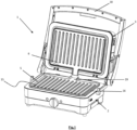
- the present invention discloses an electric cooking device 1, of the waffle iron or grill type, comprising two articulated external frames 2 and 3 as shown on the figures 1 And 2 .
- the two frames are hollow so as to form the external envelope of the device.
- each frame cooperates with a removable cooking plate 5 and 6 and accommodates a heating resistance 7.
- the two articulated parts are closed to face each other, the food being placed between them to be in contact with the two hotplates.
- the terms “lower” and “upper” qualify the elements relating respectively to the lower and upper part of the device in relation to its position on a work surface.
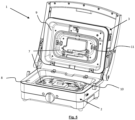
- peripheral thermal reflection plates 8 and 9 are provided inside each external frame. This reduces thermal energy losses to the outside of the appliance and reflects the heat emitted by the heating resistance towards the cooking plates.
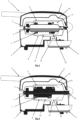
- a main drip orifice 12 is provided in the lower peripheral thermal reflection plate 8. This orifice is preferably located in a recess 17 generating a low level in the peripheral reflection plate. When liquids overflow from the cooking plates, they may seep between the lower cooking plate and the lower peripheral reflection plate, as shown in the Figure 3 . The liquids then flow by gravity towards this main drip port.
- a receptacle 4 is located under the frame, below the drain port in order to collect liquids. This receptacle can be removable for emptying.
- a thermal reflection plate for resistors 10 and 11 is also provided inside each external frame, between the peripheral thermal reflection plate and the removable cooking plate. Its purpose is to protect the electrical elements from the flow of liquids in the lower peripheral reflection plate, by being raised relative to the latter.
- the outer edges of the reflection plate for the resistors are preferably set back from the outer edges of the cooking plate, allowing liquids to preferably reach directly the bottom of the peripheral thermal reflection plate. When liquids overflow from the cooking plate, they seep between the cooking plate and the external frame and fall into the peripheral thermal reflection plate 8. As the plate for the reflection of the thermal resistance is recessed , liquids are unlikely to fall into it and the resistances are protected from this flow, as are the hanging systems and other cables.
- this includes a secondary drip orifice 13 to evacuate the liquids towards the receptacle 4, via the main drip orifice 12.
- the The secondary drip port is vertically aligned with the main drip port.
- the lower cooking plate 5 comprises a gutter 19 making it possible to evacuate the cooking juices also outside the device (see figures 1 And 4 ).
- the cooking plates are of the “grill” type.
- the cooking juices are evacuated outside the appliance, and are collected in the receptacle 4 which, in this case, protrudes from the lower frame 2 in order to collect the juices evacuated through the gutter.
- the cooking juices can take three different paths before being collected by the receptacle.
- the cooking plates 5 and 6 of the cooking device are therefore set back from the peripheral reflection plate 8 and 9, except for the gutter to allow the evacuation of the cooking juices.
- the outer edges of the resistance reflection plate 10 rise so as to form side walls surrounding the electrical elements, like a bowl, to protect them more effectively from liquids present in the lower peripheral reflection plate.
- the cooking device of the present invention also comprises a thermal insulation system to reduce heat loss to the outside of the appliance and to homogenize the heating temperature within the appliance.
- the exterior walls of the device once closed and in use, must not exceed 90°C for surfaces weakly conductive materials such as plastics and 70°C for metals, this for a maximum heating of 220 to 240°C of the cooking plates. This helps prevent the user from getting burned.
- the upper frame of the device comprises at least one insulation plate 14.
- the cooking plates have indentations 15 capable of receiving food.
- These can be of the “grill” type as illustrated on the figure 1 , “croque-monsieur” type as illustrated on the figure 2 , or any other type of shape.
- the heating resistors of each articulated part 2 and 3 can be heated independently of each other.
Description
La présente invention se rapporte à un dispositif de cuisson électrique, tel un fer à gaufre ou un grill, dans lequel la nourriture est cuite par contact avec deux plaques chauffantes inférieure et supérieure. La présente invention se rapporte en particulier à un dispositif de cuisson pourvu d'une évacuation spécifique, en cas de débordement de liquides ou de pâte.The present invention relates to an electric cooking device, such as a waffle iron or a grill, in which food is cooked by contact with two lower and upper heating plates. The present invention relates in particular to a cooking device provided with a specific evacuation, in the event of overflow of liquids or dough.
Les dispositifs de cuisson, de type fer à gaufre ou grill, sont bien connus de l'homme du métier. Ceux-ci comprennent généralement deux parties articulées comprenant chacune une plaque de cuisson ainsi qu'une résistance chauffante en contact avec cette plaque. Les deux parties articulées sont refermées lors de la cuisson se faisant face, et les aliments sont disposés entre celles-ci pour être en contact avec les deux plaques chauffantes.Cooking devices, such as waffle irons or grills, are well known to those skilled in the art. These generally include two articulated parts, each comprising a cooking plate as well as a heating resistance in contact with this plate. The two articulated parts are closed when cooking facing each other, and the food is placed between them to be in contact with the two heating plates.
Un tel dispositif est par exemple décrit dans le document
A l'heure actuelle, les conditions d'homologation de tels dispositifs sont de plus en plus sévères. Les parois extérieures du dispositif ne peuvent dépasser un certain seuil de température afin d'éviter à l'utilisateur de se brûler. L'amélioration de l'isolation de l'appareil permet d'obtenir une température de cuisson plus homogène, évitant les pointes de températures locales. Par ailleurs, une nouvelle réglementation oblige également ces dispositifs à satisfaire à un test de température en supplément du test de débordement préexistant. Le test de débordement consiste à remplir les empreintes des plaques de cuisson à 115% de leur capacité et à analyser si le dispositif est capable d'évacuer le trop plein de liquide/pâte sans que cela ne déborde de manière incontrôlée entre les deux parties articulées de l'appareil.Currently, the conditions for approval of such devices are increasingly strict. The exterior walls of the device cannot exceed a certain temperature threshold in order to prevent the user from burning themselves. Improving the insulation of the appliance makes it possible to obtain a more uniform cooking temperature, avoiding local temperature peaks. Furthermore, new regulations also require these devices to pass a temperature test in addition to the pre-existing overflow test. The overflow test consists of filling the indentations of the cooking plates to 115% of their capacity and analyzing whether the device is capable of evacuating the excess liquid/paste without it overflowing uncontrollably between the two articulated parts. of the device.
Il existe déjà des dispositifs de récupération de jus de cuisson dans le cadre des grills, mais ceci n'est pas le cas dans les appareils de cuisson de type fer à gaufre ou croque-monsieur.There are already devices for recovering cooking juices in grills, but this is not the case in waffle iron or croque-monsieur type cooking appliances.
Le document
Les appareils de cuisson de l'état de la technique ne sont pas pourvus de dispositifs d'évacuation permettant de gérer de grandes quantités de liquides. En effet, à l'heure actuelle, les dispositifs de récupération permettent de recueillir le jus de cuisson dans des conditions de fonctionnement théoriques, mais ne garantissent pas une protection satisfaisante selon les nouvelles normes. Ils n'évitent pas l'écoulement des jus hors de l'appareil entre les deux plaques de cuisson.State-of-the-art cooking appliances are not provided with evacuation devices allowing large quantities of liquids to be managed. Indeed, at present, recovery devices make it possible to collect cooking juices under theoretical operating conditions, but do not guarantee satisfactory protection according to the new standards. They do not prevent juices from flowing out of the appliance between the two cooking plates.
Le document
La présente invention vise à surmonter les inconvénients de l'état de la technique. Elle vise en particulier à fournir un appareil de cuisson électrique pourvu d'un dispositif de récupération des liquides en cas de débordement, afin d'éviter d'endommager l'appareil.The present invention aims to overcome the disadvantages of the state of the art. It aims in particular to provide an electric cooking appliance provided with a liquid recovery device in the event of overflow, in order to avoid damage to the appliance.
La présente invention permet également d'améliorer les performances thermiques de l'appareil en améliorant l'isolation de la coque.The present invention also makes it possible to improve the thermal performance of the device by improving the insulation of the shell.
La présente invention divulgue un dispositif de cuisson électrique comportant un bâti inférieur et un bâti supérieur articulés autour d'un axe de pivotement, lesdits bâtis inférieur et supérieur comprenant chacun :
- une plaque de cuisson amovible ;
- une résistance chauffante ;
- une plaque de réflexion thermique périphérique ;
- une plaque de réflexion thermique pour résistance chauffante;
- a removable cooking plate;
- a heating resistor;
- a peripheral thermal reflection plate;
- a thermal reflection plate for heating resistance;
Préférablement, l'invention comporte au moins une ou une combinaison adéquate des caractéristiques suivantes :
- la plaque de réflexion thermique pour résistance chauffante du bâti inférieur comprend un orifice d'égouttage secondaire permettant l'évacuation des liquides générés, en utilisation, vers l'orifice d'égouttage principal ;
- l'orifice d'égouttage principal est situé dans un renfoncement générant un niveau bas dans la plaque de réflexion thermique périphérique inférieure ;
- l'orifice d'égouttage secondaire est situé au-dessus de l'orifice d'égouttage principal ;
- la plaque de cuisson inférieure comprend une gouttière permettant d'évacuer les jus de cuisson à l'extérieur du dispositif et le réceptacle dépasse du bâti inférieur afin de recueillir les jus de cuisson évacués par ladite gouttière ;
- le réceptacle est amovible ;
- les plaques de cuisson sont en retrait par rapport à la plaque de réflexion périphérique à l'exception de la gouttière ;
- le réceptacle est situé à l'arrière du dispositif, en dessous du bâti inférieur;
- une structure de maintien permet de soutenir le réceptacle sous le bâti inférieur ;
- les plaques de cuisson comprennent des empreintes aptes à recevoir les aliments.
- the thermal reflection plate for heating resistor of the lower frame comprises a secondary drip orifice allowing the evacuation of liquids generated, in use, towards the main drip orifice;
- the main drip port is located in a low level generating recess in the lower peripheral thermal reflection plate;
- the secondary drip port is located above the main drip port;
- the lower cooking plate includes a gutter allowing the cooking juices to be evacuated outside the device and the receptacle protrudes from the lower frame in order to collect the cooking juices evacuated by said gutter;
- the receptacle is removable;
- the cooking plates are set back from the peripheral reflection plate with the exception of the gutter;
- the receptacle is located at the rear of the device, below the lower frame;
- a holding structure makes it possible to support the receptacle under the lower frame;
- the cooking plates include indentations capable of receiving food.
-
La
figure 1 représente un exemple de dispositif de cuisson électrique selon l'invention en position ouverte et comportant des plaques de cuisson à empreintes de type « grill ».Therefigure 1 represents an example of an electric cooking device according to the invention in the open position and comprising cooking plates with “grill” type imprints. -
La
figure 2 représente un exemple de dispositif de cuisson électrique selon l'invention en position ouverte et comportant des plaques de cuisson à empreintes de type « croque-monsieur/gaufrier ».Therefigure 2 represents an example of an electric cooking device according to the invention in the open position and comprising cooking plates with “croque-monsieur/waffle iron” type imprints. -
La
figure 3 représente une coupe transversale d'un exemple de dispositif de cuisson selon l'invention, en position fermée. Les plaques de cuisson sont de type « croque-monsieur/gaufrier » sur cette figure.ThereFigure 3 represents a cross section of an example of a cooking device according to the invention, in the closed position. The cooking plates are of the “croque-monsieur/waffle iron” type in this figure. -
La
figure 4 représente une coupe transversale d'un exemple de dispositif de cuisson selon l'invention, en position fermée. Ici les plaques de cuisson sont de type « grill ».Therefigure 4 represents a cross section of an example of a cooking device according to the invention, in the closed position. Here the cooking plates are of the “grill” type. -
La
figure 5 représente un exemple de dispositif de cuisson électrique selon l'invention, en position ouverte et sans plaques de cuisson amovibles.ThereFigure 5 represents an example of an electric cooking device according to the invention, in the open position and without removable cooking plates. -
La
figure 6 représente la première plaque de réflexion thermique du dispositif de cuisson selon l'invention.ThereFigure 6 represents the first thermal reflection plate of the cooking device according to the invention. -
La
figure 7 représente la seconde plaque de réflexion thermique du dispositif de cuisson selon l'invention.ThereFigure 7 represents the second thermal reflection plate of the cooking device according to the invention. -
La
figure 8 représente la seconde plaque de réflexion thermique du dispositif de cuisson selon l'invention, avec la résistance chauffante.Therefigure 8 represents the second thermal reflection plate of the cooking device according to the invention, with the heating resistance. -
Les
figures 9 et10 représentent deux vues en perspective d'un exemple du dispositif de cuisson selon l'invention, celui-ci étant en position fermée.THEfigures 9 And10 represent two perspective views of an example of the cooking device according to the invention, the latter being in the closed position.
- 1 : dispositif de cuisson électrique1: electric cooking device
- 2 : bâti creux inférieur du dispositif de cuisson2: lower hollow frame of the cooking device
- 3 : bâti creux supérieur du dispositif de cuisson3: upper hollow frame of the cooking device
- 4 : réceptacle de réception des liquides4: liquid reception receptacle
- 5 : plaque de cuisson amovible inférieure5: lower removable cooking plate
- 6 : plaque de cuisson amovible supérieure6: upper removable cooking plate
- 7 : résistance chauffante7: heating resistance
- 8 : plaque de réflexion thermique périphérique inférieure8: lower peripheral thermal reflection plate
- 9 : plaque de réflexion thermique périphérique supérieure9: upper peripheral thermal reflection plate
- 10 : plaque de réflexion thermique pour résistance inférieure10: thermal reflection plate for lower resistance
- 11 : plaque de réflexion thermique pour résistance supérieure11: thermal reflection plate for higher resistance
- 12 : orifice d'égouttage principal12: main drip port
- 13 : orifice d'égouttage secondaire13: secondary drip port
- 14 : plaque isolante14: insulating plate
- 15 : empreinte de plaque de cuisson15: baking tray imprint
- 16 : bords externes de la plaque de cuisson16: external edges of the cooking plate
- 17 : renfoncement dans la plaque de réflexion thermique périphérique inférieure17: recess in the lower peripheral thermal reflection plate
- 18 : poignée18: handle
- 19 : gouttière19: gutter
La présente invention divulgue un dispositif de cuisson électrique 1, de type fer à gaufre ou grill, comprenant deux bâtis externes articulés 2 et 3 tel que représenté sur les
Dans la présente description, les termes « inférieur » et « supérieur » qualifient les éléments relatifs respectivement à la partie inférieure et supérieure de l'appareil par rapport à sa position sur un plan de travail.In this description, the terms “lower” and “upper” qualify the elements relating respectively to the lower and upper part of the device in relation to its position on a work surface.
Tels que représentés sur les
Un orifice d'égouttage principal 12 est prévu dans la plaque de réflexion thermique périphérique inférieure 8. Cet orifice est préférablement situé dans un renfoncement 17 générant un niveau bas dans la plaque de réflexion périphérique. Lorsque des liquides débordent des plaques de cuisson, ceux-ci peuvent s'infiltrer entre la plaque de cuisson inférieure et la plaque de réflexion périphérique inférieure, comme illustré sur la
Une plaque de réflexion thermique pour les résistances 10 et 11 est également prévue à l'intérieur de chaque bâti externe, entre la plaque de réflexion thermique périphérique et la plaque de cuisson amovible. Elle a pour but de protéger les éléments électriques de l'écoulement des liquides dans la plaque de réflexion périphérique inférieure, en étant surélevée par rapport à cette dernière. De plus, les bords externes de la plaque de réflexion pour les résistances sont préférablement en retrait par rapport aux bords externes de la plaque de cuisson, permettant aux liquides d'atteindre préférablement directement le fond de la plaque de réflexion thermique périphérique. Lorsque des liquides débordent de la plaque de cuisson, ceux-ci s'infiltrent entre la plaque de cuisson et le bâti externe et tombent dans la plaque de réflexion thermique périphérique 8. Comme la plaque pour la réflexion de la résistance thermique se trouve en retrait, les liquides risquent peu d'y tomber et les résistances sont protégées de cet écoulement, ainsi que les systèmes d'accroches et autres câbles. Si toutefois, comme illustré sur les
De préférence, la plaque de cuisson inférieure 5 comprend une gouttière 19 permettant d'évacuer les jus de cuisson également à l'extérieur du dispositif (voir
De préférence, les bords externes de la plaque de réflexion pour résistance 10 remontent de sorte à former des parois latérales entourant les éléments électriques, comme une cuvette, pour les protéger de manière plus efficace des liquides présents dans la plaque de réflexion périphérique inférieure.Preferably, the outer edges of the
Le dispositif de cuisson de la présente invention comprend également un système d'isolation thermique pour diminuer les pertes de chaleur vers l'extérieur de l'appareil et pour homogénéiser la température de chauffe au sein de l'appareil. Les parois extérieures du dispositif, une fois fermé et en utilisation, ne doivent pas dépasser 90°C pour les surfaces faiblement conductrices comme les matières plastiques et 70 °C pour les métaux, ceci pour une chauffe de 220 à 240°C maximum des plaques de cuisson. Ceci permet d'éviter à l'utilisateur de se brûler. Comme représenté sur les
Dans un mode de réalisation avantageux de l'invention, les plaques de cuisson possèdent des empreintes 15 aptes à recevoir les aliments. Celles-ci peuvent être de type « grill » comme illustré sur la
Par ailleurs, les résistances chauffantes de chaque partie articulée 2 et 3 peuvent être chauffées indépendamment l'une de l'autre.Furthermore, the heating resistors of each articulated
Claims (8)
- An electrical cooking device (1) comprising a lower housing (2) and an upper housing (3) articulated about a pivot axis, said lower (2) and upper (3) housings each comprising:- a removable cooking plate (5, 6);- a heating resistor (7);- a peripheral heat reflecting plate (8, 9);- a heat reflecting plate for a heating resistor (10, 11);the upper housing (3) comprising at least one insulating plate (14) and the lower housing (2) comprising a main drip opening (12) in the lower peripheral heat reflecting plate (8) allowing the discharge of the produced liquids, in use, toward a receptacle (4) located below the lower housing (2), the cooking plates (5, 6) of the cooking device (1) being set back relative to the peripheral heat reflecting plate (8, 9).
- The cooking device according to claim 1, characterized in that the heat reflecting plate for the heating resistor (10) of the lower housing (2) comprises a secondary drip opening (13) allowing the discharge of the produced liquids, in use, toward the main drip opening (12).
- The cooking device according to any one of the preceding claims, characterized in that the main drip opening (12) is located in a recess (17) forming a low level in the lower peripheral heat reflecting plate (8).
- The cooking device according to any one of the preceding claims, characterized in that the lower cooking plate (5) comprises a gutter (19) allowing the cooking juices to be discharged outside the device (1) and in that the receptacle (4) protrudes past the lower housing (2) so as to collect the cooking juices discharged by said gutter (19).
- The cooking device according to any one of the preceding claims, characterized in that the receptacle (4) is removable.
- The cooking device according to any one of the preceding claims, characterized in that the receptacle (4) is located at the rear of the device (1), below the lower housing (2).
- The cooking device according to any one of the preceding claims, characterized in that a support structure (20) allows the receptacle (4) to be held below the lower housing (2).
- The cooking device according to any one of the preceding claims, characterized in that the cooking plates (5, 6) comprise cavities (15) able to receive food.
Applications Claiming Priority (2)
| Application Number | Priority Date | Filing Date | Title |
|---|---|---|---|
| EP20158211.1A EP3868265A1 (en) | 2020-02-19 | 2020-02-19 | Cooking device |
| PCT/EP2021/051041 WO2021164969A1 (en) | 2020-02-19 | 2021-01-19 | Cooking device |
Publications (2)
| Publication Number | Publication Date |
|---|---|
| EP4106587A1 EP4106587A1 (en) | 2022-12-28 |
| EP4106587B1 true EP4106587B1 (en) | 2023-11-08 |
Family
ID=69723797
Family Applications (2)
| Application Number | Title | Priority Date | Filing Date |
|---|---|---|---|
| EP20158211.1A Withdrawn EP3868265A1 (en) | 2020-02-19 | 2020-02-19 | Cooking device |
| EP21700937.2A Active EP4106587B1 (en) | 2020-02-19 | 2021-01-19 | Cooking device |
Family Applications Before (1)
| Application Number | Title | Priority Date | Filing Date |
|---|---|---|---|
| EP20158211.1A Withdrawn EP3868265A1 (en) | 2020-02-19 | 2020-02-19 | Cooking device |
Country Status (4)
| Country | Link |
|---|---|
| US (1) | US20230092589A1 (en) |
| EP (2) | EP3868265A1 (en) |
| CN (1) | CN115052504A (en) |
| WO (1) | WO2021164969A1 (en) |
Families Citing this family (2)
| Publication number | Priority date | Publication date | Assignee | Title |
|---|---|---|---|---|
| DE202018105430U1 (en) * | 2018-09-21 | 2020-01-02 | IP ideas production GmbH & Co. KG | Food delivery and preparation system |
| EP4302661A1 (en) * | 2022-06-28 | 2024-01-10 | Arçelik Anonim Sirketi | A grill comprising a grease guide |
Family Cites Families (5)
| Publication number | Priority date | Publication date | Assignee | Title |
|---|---|---|---|---|
| US3811375A (en) * | 1972-05-16 | 1974-05-21 | Gen Electric | Electric broiler |
| FR2844673B1 (en) | 2002-09-20 | 2005-07-22 | Seb Sa | HEATER SUBASSEMBLY OF ELECTRICAL APPARATUS OF THE GAUFRIER TYPE |
| US20040217109A1 (en) | 2003-05-02 | 2004-11-04 | Chang Kuei Tang | Electric baking pan |
| GR20120100576A (en) * | 2012-11-16 | 2014-06-25 | Βασιλειος Θεοδωρου Μαυριδης | Toasting device construction operating with use of heat reflection complex |
| DE102014227046A1 (en) * | 2014-12-30 | 2016-06-30 | Wmf Consumer Electric Gmbh | Waffle iron or contact grill |
-
2020
- 2020-02-19 EP EP20158211.1A patent/EP3868265A1/en not_active Withdrawn
-
2021
- 2021-01-19 WO PCT/EP2021/051041 patent/WO2021164969A1/en unknown
- 2021-01-19 US US17/904,575 patent/US20230092589A1/en active Pending
- 2021-01-19 EP EP21700937.2A patent/EP4106587B1/en active Active
- 2021-01-19 CN CN202180011476.3A patent/CN115052504A/en active Pending
Also Published As
| Publication number | Publication date |
|---|---|
| US20230092589A1 (en) | 2023-03-23 |
| EP3868265A1 (en) | 2021-08-25 |
| EP4106587A1 (en) | 2022-12-28 |
| WO2021164969A1 (en) | 2021-08-26 |
| CN115052504A (en) | 2022-09-13 |
Similar Documents
| Publication | Publication Date | Title |
|---|---|---|
| EP4106587B1 (en) | Cooking device | |
| EP0776624A1 (en) | Electrical barbecue with a frying appliance | |
| FR2539021A1 (en) | CULINARY APPARATUS FOR PREPARING SANDWICHES OF THE GENUS "HAMBURGERS" | |
| FR2794014A1 (en) | MULTI-FUNCTIONAL ELECTRIC KITCHEN APPLIANCE | |
| WO1996004832A1 (en) | Heating device for foodstuffs, particularly for frying, with an outer bowl | |
| EP3706576A1 (en) | Cooking appliance for baking mixes | |
| EP1030114B1 (en) | Removable heating sub-assembly for electric oven | |
| FR2744901A3 (en) | ELECTRIC COOKING APPLIANCE WITH TWO COOKING CHAMBERS | |
| EP2247227A2 (en) | Appliance for cooking a food product | |
| EP0248699B1 (en) | Highly efficient electric cooker, in particular for restaurant and canteen keepers | |
| FR2632510A1 (en) | BREAD GRID WHICH CAN BE ADJUSTED ACCORDING TO THE SHAPE AND QUALITY OF GRILLED BREAD SLICES | |
| EP1607030B1 (en) | Household apparatus with at least one detachable accessory | |
| FR2858537A1 (en) | ELECTRIC COOKING APPARATUS COMPRISING A DRAIN STAND | |
| EP1400193B1 (en) | Hood of an electrical waffle cooker | |
| CA3078712C (en) | Electrical cooking appliance having an draining support with a lid | |
| EP1795096B1 (en) | Cooking device | |
| EP0126663A1 (en) | Bread toaster accessory, especially for preparing toasted sandwiches | |
| FR2820194A1 (en) | ELECTRIC COOKING OVEN WITH PIVOTING HEATING ELEMENT | |
| EP1827186B1 (en) | Floating reflector for electrical barbecue | |
| WO2005020772A1 (en) | Cooking container for a heating base or an electric base | |
| FR3073128A1 (en) | COOKING APPARATUS FOR PASTRY PREPARATIONS | |
| FR3072265B1 (en) | ELECTRIC COOKING APPARATUS COMPRISING A DRAIN SUPPORT WITH STORAGE CONFIGURATION | |
| FR2878142A1 (en) | Electric household appliance e.g. waffle iron, has two sub-assemblies with heating resistors electrically connected to power supply system in connection box, where connection is made on one sub-assembly side opposite to hinge carrying side | |
| CH588245A5 (en) | ||
| EP2000066A1 (en) | Medium for cooking a small amount of food |
Legal Events
| Date | Code | Title | Description |
|---|---|---|---|
| STAA | Information on the status of an ep patent application or granted ep patent |
Free format text: STATUS: UNKNOWN |
|
| STAA | Information on the status of an ep patent application or granted ep patent |
Free format text: STATUS: THE INTERNATIONAL PUBLICATION HAS BEEN MADE |
|
| PUAI | Public reference made under article 153(3) epc to a published international application that has entered the european phase |
Free format text: ORIGINAL CODE: 0009012 |
|
| STAA | Information on the status of an ep patent application or granted ep patent |
Free format text: STATUS: REQUEST FOR EXAMINATION WAS MADE |
|
| 17P | Request for examination filed |
Effective date: 20220617 |
|
| AK | Designated contracting states |
Kind code of ref document: A1 Designated state(s): AL AT BE BG CH CY CZ DE DK EE ES FI FR GB GR HR HU IE IS IT LI LT LU LV MC MK MT NL NO PL PT RO RS SE SI SK SM TR |
|
| DAV | Request for validation of the european patent (deleted) | ||
| DAX | Request for extension of the european patent (deleted) | ||
| GRAP | Despatch of communication of intention to grant a patent |
Free format text: ORIGINAL CODE: EPIDOSNIGR1 |
|
| STAA | Information on the status of an ep patent application or granted ep patent |
Free format text: STATUS: GRANT OF PATENT IS INTENDED |
|
| INTG | Intention to grant announced |
Effective date: 20230619 |
|
| GRAS | Grant fee paid |
Free format text: ORIGINAL CODE: EPIDOSNIGR3 |
|
| GRAA | (expected) grant |
Free format text: ORIGINAL CODE: 0009210 |
|
| STAA | Information on the status of an ep patent application or granted ep patent |
Free format text: STATUS: THE PATENT HAS BEEN GRANTED |
|
| P01 | Opt-out of the competence of the unified patent court (upc) registered |
Effective date: 20230927 |
|
| AK | Designated contracting states |
Kind code of ref document: B1 Designated state(s): AL AT BE BG CH CY CZ DE DK EE ES FI FR GB GR HR HU IE IS IT LI LT LU LV MC MK MT NL NO PL PT RO RS SE SI SK SM TR |
|
| REG | Reference to a national code |
Ref country code: GB Ref legal event code: FG4D Free format text: NOT ENGLISH |
|
| REG | Reference to a national code |
Ref country code: CH Ref legal event code: EP |
|
| REG | Reference to a national code |
Ref country code: DE Ref legal event code: R096 Ref document number: 602021006663 Country of ref document: DE |
|
| REG | Reference to a national code |
Ref country code: IE Ref legal event code: FG4D Free format text: LANGUAGE OF EP DOCUMENT: FRENCH |
|
| PGFP | Annual fee paid to national office [announced via postgrant information from national office to epo] |
Ref country code: FR Payment date: 20231219 Year of fee payment: 4 |
|
| REG | Reference to a national code |
Ref country code: LT Ref legal event code: MG9D |
|
| REG | Reference to a national code |
Ref country code: NL Ref legal event code: MP Effective date: 20231108 |
|
| PG25 | Lapsed in a contracting state [announced via postgrant information from national office to epo] |
Ref country code: GR Free format text: LAPSE BECAUSE OF FAILURE TO SUBMIT A TRANSLATION OF THE DESCRIPTION OR TO PAY THE FEE WITHIN THE PRESCRIBED TIME-LIMIT Effective date: 20240209 |
|
| PG25 | Lapsed in a contracting state [announced via postgrant information from national office to epo] |
Ref country code: IS Free format text: LAPSE BECAUSE OF FAILURE TO SUBMIT A TRANSLATION OF THE DESCRIPTION OR TO PAY THE FEE WITHIN THE PRESCRIBED TIME-LIMIT Effective date: 20240308 |
|
| PG25 | Lapsed in a contracting state [announced via postgrant information from national office to epo] |
Ref country code: LT Free format text: LAPSE BECAUSE OF FAILURE TO SUBMIT A TRANSLATION OF THE DESCRIPTION OR TO PAY THE FEE WITHIN THE PRESCRIBED TIME-LIMIT Effective date: 20231108 |
|
| REG | Reference to a national code |
Ref country code: AT Ref legal event code: MK05 Ref document number: 1628847 Country of ref document: AT Kind code of ref document: T Effective date: 20231108 |
|
| PG25 | Lapsed in a contracting state [announced via postgrant information from national office to epo] |
Ref country code: NL Free format text: LAPSE BECAUSE OF FAILURE TO SUBMIT A TRANSLATION OF THE DESCRIPTION OR TO PAY THE FEE WITHIN THE PRESCRIBED TIME-LIMIT Effective date: 20231108 |
|
| PG25 | Lapsed in a contracting state [announced via postgrant information from national office to epo] |
Ref country code: AT Free format text: LAPSE BECAUSE OF FAILURE TO SUBMIT A TRANSLATION OF THE DESCRIPTION OR TO PAY THE FEE WITHIN THE PRESCRIBED TIME-LIMIT Effective date: 20231108 |