EP4106137A1 - Power supply unit and vehicle - Google Patents
Power supply unit and vehicle Download PDFInfo
- Publication number
- EP4106137A1 EP4106137A1 EP22179628.7A EP22179628A EP4106137A1 EP 4106137 A1 EP4106137 A1 EP 4106137A1 EP 22179628 A EP22179628 A EP 22179628A EP 4106137 A1 EP4106137 A1 EP 4106137A1
- Authority
- EP
- European Patent Office
- Prior art keywords
- power
- supply unit
- power supply
- converter
- vehicle
- Prior art date
- Legal status (The legal status is an assumption and is not a legal conclusion. Google has not performed a legal analysis and makes no representation as to the accuracy of the status listed.)
- Pending
Links
Images



Classifications
-
- H—ELECTRICITY
- H02—GENERATION; CONVERSION OR DISTRIBUTION OF ELECTRIC POWER
- H02J—ELECTRIC POWER NETWORKS; CIRCUIT ARRANGEMENTS OR SYSTEMS FOR SUPPLYING OR DISTRIBUTING ELECTRIC POWER; SYSTEMS FOR STORING ELECTRIC ENERGY
- H02J7/00—Circuit arrangements for charging or discharging batteries or for supplying loads from batteries
- H02J7/70—Circuit arrangements for charging or discharging batteries or for supplying loads from batteries characterised by the mechanical construction
-
- H—ELECTRICITY
- H02—GENERATION; CONVERSION OR DISTRIBUTION OF ELECTRIC POWER
- H02J—ELECTRIC POWER NETWORKS; CIRCUIT ARRANGEMENTS OR SYSTEMS FOR SUPPLYING OR DISTRIBUTING ELECTRIC POWER; SYSTEMS FOR STORING ELECTRIC ENERGY
- H02J7/00—Circuit arrangements for charging or discharging batteries or for supplying loads from batteries
- H02J7/855—Circuit arrangements for charging or discharging batteries or for supplying loads from batteries with circuits adapted for supplying loads from the battery
-
- H—ELECTRICITY
- H02—GENERATION; CONVERSION OR DISTRIBUTION OF ELECTRIC POWER
- H02J—ELECTRIC POWER NETWORKS; CIRCUIT ARRANGEMENTS OR SYSTEMS FOR SUPPLYING OR DISTRIBUTING ELECTRIC POWER; SYSTEMS FOR STORING ELECTRIC ENERGY
- H02J7/00—Circuit arrangements for charging or discharging batteries or for supplying loads from batteries
- H02J7/865—Battery or charger load switching, e.g. concurrent charging and load supply
-
- B—PERFORMING OPERATIONS; TRANSPORTING
- B60—VEHICLES IN GENERAL
- B60L—PROPULSION OF ELECTRICALLY-PROPELLED VEHICLES; SUPPLYING ELECTRIC POWER FOR AUXILIARY EQUIPMENT OF ELECTRICALLY-PROPELLED VEHICLES; ELECTRODYNAMIC BRAKE SYSTEMS FOR VEHICLES IN GENERAL; MAGNETIC SUSPENSION OR LEVITATION FOR VEHICLES; MONITORING OPERATING VARIABLES OF ELECTRICALLY-PROPELLED VEHICLES; ELECTRIC SAFETY DEVICES FOR ELECTRICALLY-PROPELLED VEHICLES
- B60L1/00—Supplying electric power to auxiliary equipment of vehicles
-
- B—PERFORMING OPERATIONS; TRANSPORTING
- B60—VEHICLES IN GENERAL
- B60L—PROPULSION OF ELECTRICALLY-PROPELLED VEHICLES; SUPPLYING ELECTRIC POWER FOR AUXILIARY EQUIPMENT OF ELECTRICALLY-PROPELLED VEHICLES; ELECTRODYNAMIC BRAKE SYSTEMS FOR VEHICLES IN GENERAL; MAGNETIC SUSPENSION OR LEVITATION FOR VEHICLES; MONITORING OPERATING VARIABLES OF ELECTRICALLY-PROPELLED VEHICLES; ELECTRIC SAFETY DEVICES FOR ELECTRICALLY-PROPELLED VEHICLES
- B60L15/00—Methods, circuits, or devices for controlling the traction-motor speed of electrically-propelled vehicles
- B60L15/007—Physical arrangements or structures of drive train converters specially adapted for the propulsion motors of electric vehicles
-
- B—PERFORMING OPERATIONS; TRANSPORTING
- B60—VEHICLES IN GENERAL
- B60L—PROPULSION OF ELECTRICALLY-PROPELLED VEHICLES; SUPPLYING ELECTRIC POWER FOR AUXILIARY EQUIPMENT OF ELECTRICALLY-PROPELLED VEHICLES; ELECTRODYNAMIC BRAKE SYSTEMS FOR VEHICLES IN GENERAL; MAGNETIC SUSPENSION OR LEVITATION FOR VEHICLES; MONITORING OPERATING VARIABLES OF ELECTRICALLY-PROPELLED VEHICLES; ELECTRIC SAFETY DEVICES FOR ELECTRICALLY-PROPELLED VEHICLES
- B60L53/00—Methods of charging batteries, specially adapted for electric vehicles; Charging stations or on-board charging equipment therefor; Exchange of energy storage elements in electric vehicles
- B60L53/10—Methods of charging batteries, specially adapted for electric vehicles; Charging stations or on-board charging equipment therefor; Exchange of energy storage elements in electric vehicles characterised by the energy transfer between the charging station and the vehicle
- B60L53/14—Conductive energy transfer
-
- B—PERFORMING OPERATIONS; TRANSPORTING
- B60—VEHICLES IN GENERAL
- B60L—PROPULSION OF ELECTRICALLY-PROPELLED VEHICLES; SUPPLYING ELECTRIC POWER FOR AUXILIARY EQUIPMENT OF ELECTRICALLY-PROPELLED VEHICLES; ELECTRODYNAMIC BRAKE SYSTEMS FOR VEHICLES IN GENERAL; MAGNETIC SUSPENSION OR LEVITATION FOR VEHICLES; MONITORING OPERATING VARIABLES OF ELECTRICALLY-PROPELLED VEHICLES; ELECTRIC SAFETY DEVICES FOR ELECTRICALLY-PROPELLED VEHICLES
- B60L53/00—Methods of charging batteries, specially adapted for electric vehicles; Charging stations or on-board charging equipment therefor; Exchange of energy storage elements in electric vehicles
- B60L53/20—Methods of charging batteries, specially adapted for electric vehicles; Charging stations or on-board charging equipment therefor; Exchange of energy storage elements in electric vehicles characterised by converters located in the vehicle
- B60L53/22—Constructional details or arrangements of charging converters specially adapted for charging electric vehicles
-
- B—PERFORMING OPERATIONS; TRANSPORTING
- B60—VEHICLES IN GENERAL
- B60R—VEHICLES, VEHICLE FITTINGS, OR VEHICLE PARTS, NOT OTHERWISE PROVIDED FOR
- B60R16/00—Electric or fluid circuits specially adapted for vehicles and not otherwise provided for; Arrangement of elements of electric or fluid circuits specially adapted for vehicles and not otherwise provided for
- B60R16/02—Electric or fluid circuits specially adapted for vehicles and not otherwise provided for; Arrangement of elements of electric or fluid circuits specially adapted for vehicles and not otherwise provided for electric constitutive elements
- B60R16/03—Electric or fluid circuits specially adapted for vehicles and not otherwise provided for; Arrangement of elements of electric or fluid circuits specially adapted for vehicles and not otherwise provided for electric constitutive elements for supply of electrical power to vehicle subsystems or for
- B60R16/033—Electric or fluid circuits specially adapted for vehicles and not otherwise provided for; Arrangement of elements of electric or fluid circuits specially adapted for vehicles and not otherwise provided for electric constitutive elements for supply of electrical power to vehicle subsystems or for characterised by the use of electrical cells or batteries
-
- H—ELECTRICITY
- H02—GENERATION; CONVERSION OR DISTRIBUTION OF ELECTRIC POWER
- H02J—ELECTRIC POWER NETWORKS; CIRCUIT ARRANGEMENTS OR SYSTEMS FOR SUPPLYING OR DISTRIBUTING ELECTRIC POWER; SYSTEMS FOR STORING ELECTRIC ENERGY
- H02J7/00—Circuit arrangements for charging or discharging batteries or for supplying loads from batteries
- H02J7/34—Parallel operation in networks using both storage and other DC sources, e.g. providing buffering
- H02J7/35—Parallel operation in networks using both storage and other DC sources, e.g. providing buffering with light sensitive cells
-
- B—PERFORMING OPERATIONS; TRANSPORTING
- B60—VEHICLES IN GENERAL
- B60L—PROPULSION OF ELECTRICALLY-PROPELLED VEHICLES; SUPPLYING ELECTRIC POWER FOR AUXILIARY EQUIPMENT OF ELECTRICALLY-PROPELLED VEHICLES; ELECTRODYNAMIC BRAKE SYSTEMS FOR VEHICLES IN GENERAL; MAGNETIC SUSPENSION OR LEVITATION FOR VEHICLES; MONITORING OPERATING VARIABLES OF ELECTRICALLY-PROPELLED VEHICLES; ELECTRIC SAFETY DEVICES FOR ELECTRICALLY-PROPELLED VEHICLES
- B60L2210/00—Converter types
- B60L2210/10—DC to DC converters
-
- B—PERFORMING OPERATIONS; TRANSPORTING
- B60—VEHICLES IN GENERAL
- B60L—PROPULSION OF ELECTRICALLY-PROPELLED VEHICLES; SUPPLYING ELECTRIC POWER FOR AUXILIARY EQUIPMENT OF ELECTRICALLY-PROPELLED VEHICLES; ELECTRODYNAMIC BRAKE SYSTEMS FOR VEHICLES IN GENERAL; MAGNETIC SUSPENSION OR LEVITATION FOR VEHICLES; MONITORING OPERATING VARIABLES OF ELECTRICALLY-PROPELLED VEHICLES; ELECTRIC SAFETY DEVICES FOR ELECTRICALLY-PROPELLED VEHICLES
- B60L2210/00—Converter types
- B60L2210/10—DC to DC converters
- B60L2210/12—Buck converters
-
- B—PERFORMING OPERATIONS; TRANSPORTING
- B60—VEHICLES IN GENERAL
- B60L—PROPULSION OF ELECTRICALLY-PROPELLED VEHICLES; SUPPLYING ELECTRIC POWER FOR AUXILIARY EQUIPMENT OF ELECTRICALLY-PROPELLED VEHICLES; ELECTRODYNAMIC BRAKE SYSTEMS FOR VEHICLES IN GENERAL; MAGNETIC SUSPENSION OR LEVITATION FOR VEHICLES; MONITORING OPERATING VARIABLES OF ELECTRICALLY-PROPELLED VEHICLES; ELECTRIC SAFETY DEVICES FOR ELECTRICALLY-PROPELLED VEHICLES
- B60L2210/00—Converter types
- B60L2210/30—AC to DC converters
-
- H—ELECTRICITY
- H02—GENERATION; CONVERSION OR DISTRIBUTION OF ELECTRIC POWER
- H02J—ELECTRIC POWER NETWORKS; CIRCUIT ARRANGEMENTS OR SYSTEMS FOR SUPPLYING OR DISTRIBUTING ELECTRIC POWER; SYSTEMS FOR STORING ELECTRIC ENERGY
- H02J2105/00—Networks for supplying or distributing electric power characterised by their spatial reach or by the load
- H02J2105/30—Networks for supplying or distributing electric power characterised by their spatial reach or by the load the load networks being external to vehicles, i.e. exchanging power with vehicles
- H02J2105/33—Networks for supplying or distributing electric power characterised by their spatial reach or by the load the load networks being external to vehicles, i.e. exchanging power with vehicles exchanging power with road vehicles
- H02J2105/37—Networks for supplying or distributing electric power characterised by their spatial reach or by the load the load networks being external to vehicles, i.e. exchanging power with vehicles exchanging power with road vehicles exchanging power with electric vehicles [EV] or with hybrid electric vehicles [HEV]
-
- H—ELECTRICITY
- H02—GENERATION; CONVERSION OR DISTRIBUTION OF ELECTRIC POWER
- H02J—ELECTRIC POWER NETWORKS; CIRCUIT ARRANGEMENTS OR SYSTEMS FOR SUPPLYING OR DISTRIBUTING ELECTRIC POWER; SYSTEMS FOR STORING ELECTRIC ENERGY
- H02J2207/00—Details of circuit arrangements for charging or discharging batteries or supplying loads from batteries
- H02J2207/20—Charging or discharging characterised by the power electronics converter
-
- H—ELECTRICITY
- H02—GENERATION; CONVERSION OR DISTRIBUTION OF ELECTRIC POWER
- H02J—ELECTRIC POWER NETWORKS; CIRCUIT ARRANGEMENTS OR SYSTEMS FOR SUPPLYING OR DISTRIBUTING ELECTRIC POWER; SYSTEMS FOR STORING ELECTRIC ENERGY
- H02J2207/00—Details of circuit arrangements for charging or discharging batteries or supplying loads from batteries
- H02J2207/40—Details of circuit arrangements for charging or discharging batteries or supplying loads from batteries adapted for charging from various sources, e.g. AC, DC or multivoltage
-
- H—ELECTRICITY
- H02—GENERATION; CONVERSION OR DISTRIBUTION OF ELECTRIC POWER
- H02J—ELECTRIC POWER NETWORKS; CIRCUIT ARRANGEMENTS OR SYSTEMS FOR SUPPLYING OR DISTRIBUTING ELECTRIC POWER; SYSTEMS FOR STORING ELECTRIC ENERGY
- H02J7/00—Circuit arrangements for charging or discharging batteries or for supplying loads from batteries
- H02J7/02—Circuit arrangements for charging or discharging batteries or for supplying loads from batteries for charging batteries from AC mains by converters
-
- Y—GENERAL TAGGING OF NEW TECHNOLOGICAL DEVELOPMENTS; GENERAL TAGGING OF CROSS-SECTIONAL TECHNOLOGIES SPANNING OVER SEVERAL SECTIONS OF THE IPC; TECHNICAL SUBJECTS COVERED BY FORMER USPC CROSS-REFERENCE ART COLLECTIONS [XRACs] AND DIGESTS
- Y02—TECHNOLOGIES OR APPLICATIONS FOR MITIGATION OR ADAPTATION AGAINST CLIMATE CHANGE
- Y02T—CLIMATE CHANGE MITIGATION TECHNOLOGIES RELATED TO TRANSPORTATION
- Y02T10/00—Road transport of goods or passengers
- Y02T10/60—Other road transportation technologies with climate change mitigation effect
- Y02T10/70—Energy storage systems for electromobility, e.g. batteries
-
- Y—GENERAL TAGGING OF NEW TECHNOLOGICAL DEVELOPMENTS; GENERAL TAGGING OF CROSS-SECTIONAL TECHNOLOGIES SPANNING OVER SEVERAL SECTIONS OF THE IPC; TECHNICAL SUBJECTS COVERED BY FORMER USPC CROSS-REFERENCE ART COLLECTIONS [XRACs] AND DIGESTS
- Y02—TECHNOLOGIES OR APPLICATIONS FOR MITIGATION OR ADAPTATION AGAINST CLIMATE CHANGE
- Y02T—CLIMATE CHANGE MITIGATION TECHNOLOGIES RELATED TO TRANSPORTATION
- Y02T10/00—Road transport of goods or passengers
- Y02T10/60—Other road transportation technologies with climate change mitigation effect
- Y02T10/7072—Electromobility specific charging systems or methods for batteries, ultracapacitors, supercapacitors or double-layer capacitors
Definitions
- the present disclosure relates to a power supply unit and a vehicle comprising the power supply unit.
- Japanese Patent Laying-Open No. 2011-020553 discloses a power apparatus mounted in a vehicle and including a charger that receives low-voltage power through a low-voltage port and converts the received low-voltage power into high voltage and a circuit box having a plurality of relays and a DC/DC converter incorporated therein.
- the charger is located at a rear portion of the vehicle and the circuit box is located at a front portion of the vehicle.
- the power apparatus disclosed in Japanese Patent Laying-Open No. 2011-020553 however, has the charger and the circuit box disposed at the rear portion and front portion, respectively, of the vehicle with a considerable distance therebetween, and thus has its constituent parts mounted inefficiently.
- a plurality of power converters such as a charger and a DC/DC converter may be disposed close to one another.
- a power conversion device is relatively heavy in weight, and when the power conversion device is disposed without any consideration, a large moment is input by vibration, which may decrease durability or affect the vehicle's behavior.
- the present disclosure has been made in view of the above problem, and an object of the present disclosure is to provide a power supply unit and vehicle capable of reducing a moment that acts through vibration while increasing efficiency of mounting parts in the vehicle.
- a power supply unit includes a current path, and is capable of receiving external power from an external power supply and supplying the received external power to a power storage device, and receiving power from the power storage device and supplying the received power to a device mounted in a vehicle.
- the power supply unit comprises one or more power converters, a relay that switches the current path, and a housing that accommodates the one or more power converters and the relay therein.
- the one or more power converters are heavier in weight than the relay and are disposed in the housing below the relay.
- the one or more power converters and the relay are accommodated in the housing of the power supply unit and thus disposed close to one another, and can thus be mounted in the vehicle more efficiently. Further, disposing the one or more heavy power converters below the lightweight relay allows the power supply unit to have a center of gravity at a low level. This can reduce a moment acting on the power supply unit through vibration.
- the relay is provided on the current path between an inlet to which the external power supply is connected and the power storage device, and switches a state in which the inlet and the power storage device are electrically connected to each other to a state in which the inlet and the power storage device are electrically disconnected from each other, and vice versa.
- the relay provided on the current path between the inlet to which the external power supply is connected and the power storage device and the one or more power converters can be disposed in the housing such that the relay and the one or more power converters are close to one another.
- the power supply unit according to the present disclosure may further comprise a control device that is accommodated in the housing and controls an operation of the relay and that of the one or more power converters.
- the control device be lighter in weight than the one or more power converters and disposed in the housing above the one or more power converters.
- the control device is further accommodated in the housing, and efficiency of mounting in the vehicle can be improved. Further, disposing the one or more heavy power converters at a lower level and the lightweight control device at an upper level allows the power supply unit to have a center of gravity at a low level. This can reduce a moment acting on the power supply unit through vibration.
- the one or more power converters may include a plurality of power converters.
- the heaviest one of the plurality of power converters be disposed in the housing at the same level as the other power converters or a level lower than the other power converters.
- the one or more power converters may include a first power converter that receives AC power from an AC power supply external to the vehicle and converts the received AC power into power chargeable to the power storage device, and a second power converter that receives power from the power storage device and converts the received power into power supplied to an auxiliary device mounted in the vehicle.
- the first power converter be heavier in weight than the second power converter and disposed in the housing below the second power converter.
- the first power converter and the second power converter in the housing, efficiency of mounting in the vehicle can be improved. Further, disposing the first power converter that is heavier in weight than the second power converter below the second power converter allows the power supply unit to have a center of gravity at a low level. This can reduce a moment acting on the power supply unit through vibration.
- the one or more power converters may further include a third power converter that converts an output of the first power converter into power supplied to the auxiliary device mounted in the vehicle.
- the first power converter be heavier in weight than the second power converter and the third power converter, and disposed in the housing below the second power converter and the third power converter.
- the first power converter, the second power converter and the third power converter in the housing, efficiency of mounting in the vehicle can be improved. Further, disposing the first power converter that is heavier in weight than the second power converter and the third power converter below the second power converter and the third power converter allows the power supply unit to have a center of gravity at a low level. This can reduce a moment acting on the power supply unit through vibration.
- a vehicle comprises the power supply unit and the auxiliary device.
- the second power converter and the third power converter may be connected to the auxiliary device.
- the vehicle provided with the auxiliary device can achieve improved mounting efficiency and reduce a moment acting on the power supply unit through vibration.
- a vehicle comprises the power supply unit and a transaxle.
- the power supply unit is disposed above the transaxle.
- the transaxle is susceptible to vibration, and according to the above configuration, the power supply unit is disposed above the transaxle, and a moment acting on the power supply unit through vibration can be effectively reduced.
- a vehicle comprises the power supply unit, the power storage device, and a floor panel that allows the power storage device to be mounted.
- the power storage device is disposed below the floor panel at a location on the vehicle rearwardly of the power supply unit.
- Fig. 1 is a diagram of a configuration of a power apparatus according to a first embodiment.
- a power apparatus 100 according to the first embodiment will be described with reference to Fig. 1 .
- Power apparatus 100 is mounted in a vehicle 1 (see Fig. 3 ).
- Vehicle 1 is a hybrid electric vehicle that can travel using power of at least one of a motor and an engine, or an electrically powered vehicle that travels using a driving force obtained through electric energy.
- power apparatus 100 includes a power storage device 10, a power supply unit 20, an AC (alternating current) inlet 31 as a first inlet, a DC (direct current) inlet 32 as a second inlet, a low voltage auxiliary device 40, a high voltage auxiliary device 41, a front power control unit (Fr_PCU) 61, a rear power control unit (Rr_PCU) 62, and a solar charger 70.
- a power storage device 10 includes a power storage device 10, a power supply unit 20, an AC (alternating current) inlet 31 as a first inlet, a DC (direct current) inlet 32 as a second inlet, a low voltage auxiliary device 40, a high voltage auxiliary device 41, a front power control unit (Fr_PCU) 61, a rear power control unit (Rr_PCU) 62, and a solar charger 70.
- Fr_PCU front power control unit
- Rr_PCU rear power control unit
- Power storage device 10 is mounted in vehicle 1 as a driving power source for vehicle 1.
- Power storage device 10 includes a battery pack 11, a system main relay (SMR1, SMR2) 15, and a charging relay 16 (CHR1, CHR2).
- SMR1, SMR2 system main relay
- CHR1, CHR2 charging relay 16
- Battery pack 11 is composed of a plurality of unit cells stacked in layers.
- the unit cell is, for example, a secondary battery such as a nickel metal hydride battery or a lithium-ion battery.
- a unit cell C1 may use a liquid electrolyte or a solid electrolyte.
- a capacitor may be used instead of the unit cell.
- Power storage device 10 is connected to a DC relay 23, which will be described hereinafter, by a power line 53.
- Power line 53 is branched into a power line 53a, and power line 53a is connected to front power control unit 61.
- Ferrite cores 91 and 92 as a noise countermeasure member are attached to power line 53a.
- a ferrite core 93 as a noise countermeasure member is also attached to a power line 53a5, which will be described hereinafter.
- Power storage device 10 is connected to an AC charger 22 that serves as a first power converter by a power line 52.
- Solar charger 70 may be connected to power line 52.
- System main relay 15 is provided on power line 53 between battery pack 11 and DC relay 23.
- System main relay 15 is switched on/off by a charging integration ECU 26 serving as an electronic control unit, which will be described hereinafter.
- Charging relay 16 is provided on power line 52 between battery pack 11 and AC charger 22. Charging relay 16 is switched on/off by charging integration ECU 26.
- Power supply unit 20 includes a current path, a housing 21, AC charger 22, DC relay 23, a main DC/DC converter 24 as a second power converter, a sub DC/DC converter 25 as a third power converter, charging integration ECU 26, and connectors 82, 83 and 84.
- the current path is composed of a portion of power lines 52, 53, and 53a described above and power lines 51, 53a1, 53a2, 53a3, 53a4, 54, 55, 56, 57 described hereinafter, that is routed in housing 21.
- Charging integration ECU 26 controls operation of AC charger 22, DC relay 23, main DC/DC converter 24, and sub DC/DC converter 25. Charging integration ECU 26 is connected to an ECU of a higher level (not shown) and can communicate with the ECU. Charging integration ECU 26 can sense the temperature of power line 54.
- AC charger 22, DC relay 23, main DC/DC converter 24, sub DC/DC converter 25, and charging integration ECU 26 are disposed inside housing 21.
- Connectors 82, 83, and 84 are provided on a side surface of the housing.
- Connectors 82, 83, and 84 have a fuse. The fuse is configured to interrupt a current path when a current exceeding the fuse's rated current passes through the fuse.
- AC charger 22 is connected to battery pack 11 by power line 52, as described above. AC charger 22 is also connected to AC inlet 31 by power line 51.
- AC inlet 31 allows a first external power supply 71, which is an AC power supply, to be connected thereto.
- AC charger 22 receives AC power from first external power supply 71 via power line 51 and converts the received AC power into DC power chargeable to power storage device 10.
- battery pack 11 When charging relay 16 is in the ON state, battery pack 11 is charged with power converted by AC charger 22 into DC power.
- battery pack 11 may also be charged with power received from solar charger 70.
- AC charger 22 has a fuse, and the fuse is configured to interrupt a current path when a current exceeding the fuse's rated current passes through the fuse.
- DC relay 23 is connected to battery pack 11 by power line 53, as described above.
- DC relay 23 is also connected to DC inlet 32 by power line 54. That is, DC relay 23 is provided on a current path between DC inlet 32 and power storage device 10.
- DC inlet 32 allows a second external power supply 72, which is a DC power supply, to be connected thereto.
- DC relay 23 is connected to charging integration ECU 26 and switched on/off by charging integration ECU 26. That is, DC relay 23 switches a state in which DC inlet 32 and power storage device 10 are electrically connected to each other to a state in which DC inlet 32 and power storage device 10 are electrically disconnected from each other, and vice versa.
- DC relay 23 and system main relay 15 are in the ON state, DC power supplied from the second external power supply via power line 54 is charged to battery pack 11 through power line 53. In this case, battery pack 11 can be charged rapidly.
- Main DC/DC converter 24 is connected via power line 53a1 to power line 53a aforementioned.
- Main DC/DC converter 24 is connected to low-voltage auxiliary device 40 via power line 57.
- Main DC/DC converter 24 receives power from power storage device 10 and converts the received power into power to be supplied to an auxiliary device mounted in the vehicle. Specifically, main DC/DC converter 24 receives power from battery pack 11, decreases the received power in voltage, and supplies low-voltage auxiliary device 40 with the power decreased in voltage. Low-voltage auxiliary device 40 is, for example, an illumination device, an audio device, a power steering device, or the like. As well as AC charger 22, main DC/DC converter 24 also has a fuse.
- Sub DC/DC converter 25 is connected to AC charger 22 by power line 55.
- Sub DC/DC converter 25 is connected to low-voltage auxiliary device 40 by power line 56.
- Sub DC/DC converter 25 has a power capacity smaller than that of main DC/DC converter 24.
- Sub DC/DC converter 25 converts an output of AC charger 22 into power to be supplied to the auxiliary device mounted in the vehicle. Specifically, sub DC/DC converter 25 receives power converted by AC charger 22 into a DC current, decreases the received power in voltage, and supplies low-voltage auxiliary device 40 with the power decreased in voltage. As well as AC charger 22, sub DC/DC converter 25 also has a fuse.
- Connector 82 is connected to battery pack 11 by power lines 53, 53a, and 53a2.
- Connector 83 is connected to battery pack 11 by power lines 53, 53a, and 53a3.
- Connector 84 is connected to battery pack 11 by power lines 53, 53a, and 53a4.
- High-voltage auxiliary device 41 includes a water heater 42, an air conditioner 43, and an AC 100V inverter 44.
- Water heater 42 is connected to connector 82.
- Water heater 42 is a heater that heats an interior of a compartment of the vehicle.
- Water heater 42 has a pipe, for example, and indirectly heats air by heating water circulating through the pipe.
- Air conditioner 43 is connected to connector 83.
- Air conditioner 43 includes a compressor and operates the compressor in response to a control signal received from an ECU to perform air conditioning of the compartment of the vehicle.
- AC 100V inverter 44 is connected to connector 84.
- AC 100V inverter 44 is mounted in vehicle 1 as a spare device for main DC/DC converter 24.
- AC 100V inverter 44 is, for example, an in-vehicle receptacle. AC 100V inverter 44 may be dispensed with.
- Front power control unit 61 and rear power control unit 62 are provided as described above.
- Front power control unit 61 is connected to battery pack 11 by power lines 53 and 53a.
- Rear power control unit 62 is connected to battery pack 11 by power lines 53, 53a, and 53a5.
- Front power control unit 61 and rear power control unit 62 receive power from power storage device 10 to drive a motor generator.
- Front power control unit 61 and rear power control unit 62 include, for example, an inverter for driving the motor generator, a converter for receiving power output from power storage device 10, increasing the received power in voltage, and supplying the inverter with the power increased in voltage, and the like.
- rear power control unit 62 may be dispensed with.
- Fig. 2 is a schematic diagram showing a positional relationship between components constituting the power supply unit according to the first embodiment. Referring to Fig. 2 , the positional relationship between components constituting the power supply unit will be described.
- charging integration ECU 26 and DC relay 23 are disposed in housing 21 at an upper portion. Charging integration ECU 26 and DC relay 23 are disposed at the same hierarchical level.
- Main DC/DC converter 24 and sub DC/DC converter 25 are disposed in housing 21 at a middle portion. Main DC/DC converter 24 and sub DC/DC converter 25 are disposed at the same hierarchical level.
- AC charger 22 is disposed in housing 21 at a lower portion.
- charging integration ECU 26 and DC relay 23 are disposed in housing 21 above AC charger 22 and above main DC/DC converter 24 and sub DC/DC converter 25.
- Main DC/DC converter 24 and sub DC/DC converter 25 are disposed in housing 21 below charging integration ECU 26 and DC relay 23 and above AC charger 22.
- AC charger 22 is heavier in weight than main DC/DC converter 24 and sub DC/DC converter 25, and heaviest among the power converters of AC charger 22, main DC/DC converter 24, and sub DC/DC converter 25.
- charging integration ECU 26 and DC relay 23 are lighter in weight than AC charger 22, and furthermore, lighter in weight than main DC/DC converter 24 and sub DC/DC converter 25.
- Fig. 3 is a schematic diagram showing a position of the power supply unit mounted in the vehicle according to the first embodiment. The position of power supply unit 20 mounted in vehicle 1 will be described with reference to Fig. 3 .
- vehicle 1 comprises a floor panel 2, a dash panel 3, a transaxle 5, a support member 6, power storage device 10, and power supply unit 20.
- Power storage device 10 is disposed under floor panel 2 rearwardly of power supply unit 20. This can stabilize a balance in weight longitudinally of vehicle 1.
- Transaxle 5, support member 6, and power supply unit 20 are installed in a front compartment 4 located in front of dash panel 3.
- Support member 6 may be fixed to dash panel 3, or may be fixed by a member (not shown) to a frame of the vehicle, such as a cross member or a side member.
- Power supply unit 20 is disposed above transaxle 5 and supported by support member 6.
- power supply unit 20 When power supply unit 20 is disposed above transaxle 5, power supply unit 20 is easily affected by vibration received from vehicle 1 including vibration of transaxle 5.
- main DC/DC converter 24 and sub DC/DC converter 25 When disposing AC charger 22, main DC/DC converter 24 and sub DC/DC converter 25 in housing 21 and thus lowering the center of gravity of power supply unit 20 in level, as described above, is compared with having the center of gravity at a high level as indicated in Fig. 3 by a broken line arrow AR1, the former can reduce a moment acting on power supply unit 20 through vibration, as indicated in Fig. 3 by a solid line arrow AR2.
- Fig. 4 is a diagram of a configuration of a power apparatus according to a second embodiment.
- a power apparatus 100A according to the second embodiment will be described with reference to Fig. 4 .
- power apparatus 100A according to the second embodiment is different from power apparatus 100 according to the first embodiment in that a power supply unit 20A dispenses with sub DC/DC converter 25.
- the remainder in configuration is substantially identical.
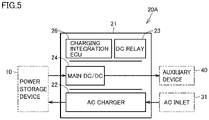
- Fig. 5 is a schematic diagram showing a positional relationship between components constituting the power supply unit according to the second embodiment. Referring to Fig. 5 , the positional relationship between the components constituting power supply unit 20A will be described.
- power supply unit 20A has charging integration ECU 26 and DC relay 23 disposed in housing 21 above AC charger 22 and above main DC/DC converter 24.
- Main DC/DC converter 24 is disposed in housing 21 below charging integration ECU 26 and DC relay 23 and above AC charger 22.
- power supply unit 20A can be lightweight.
- Fig. 6 is a diagram of a configuration of a power apparatus according to a third embodiment. Referring to Fig. 6 , a description will be given of a power apparatus 100B according to the third embodiment.
- power apparatus 100B according to the third embodiment differs from power apparatus 100 according to the first embodiment in that power supply unit 20B dispenses with main DC/DC converter 24 and sub DC/DC converter 25.
- the remainder in configuration is substantially identical.
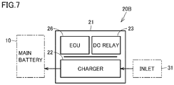
- Fig. 7 is a schematic diagram showing a positional relationship between components constituting the power supply unit according to the third embodiment. Referring to Fig. 7 , the positional relationship between the components constituting power supply unit 20B will be described.
- power supply unit 20B has charging integration ECU 26 and DC relay 23 disposed in housing 21 above AC charger 22, and power supply unit 20B can thus have a center of gravity at a low level.
- power supply unit 20B according to the third embodiment is also substantially as effective as power supply unit 20 according to the first embodiment.
- power supply unit 20B can be lightweight.
Landscapes
- Engineering & Computer Science (AREA)
- Power Engineering (AREA)
- Mechanical Engineering (AREA)
- Transportation (AREA)
- Charge And Discharge Circuits For Batteries Or The Like (AREA)
- Electric Propulsion And Braking For Vehicles (AREA)
- Arrangement Or Mounting Of Propulsion Units For Vehicles (AREA)
Abstract
A power supply unit includes a current path, and is capable of receiving external power from an external power supply and supplying the received external power to a power storage device (10), and receiving power from the power storage device (10) and supplying the received power to a device mounted in a vehicle. The power supply unit comprises one or more power converters, a relay (23) that switches the current path, and a housing (21) that accommodates the one or more power converters and the relay (23) therein. The one or more power converters are heavier in weight than the relay (23) and disposed in the housing (21) below the relay (23).
Description
- This nonprovisional application is based on
Japanese Patent Application No. 2021-101467 filed on June 18, 2021 - The present disclosure relates to a power supply unit and a vehicle comprising the power supply unit.
- Conventionally,
Japanese Patent Laying-Open No. 2011-020553 - The power apparatus disclosed in
Japanese Patent Laying-Open No. 2011-020553 - In order to mount parts more efficiently, a plurality of power converters such as a charger and a DC/DC converter may be disposed close to one another. On the other hand, a power conversion device is relatively heavy in weight, and when the power conversion device is disposed without any consideration, a large moment is input by vibration, which may decrease durability or affect the vehicle's behavior.
- The present disclosure has been made in view of the above problem, and an object of the present disclosure is to provide a power supply unit and vehicle capable of reducing a moment that acts through vibration while increasing efficiency of mounting parts in the vehicle.
- A power supply unit according to the present disclosure includes a current path, and is capable of receiving external power from an external power supply and supplying the received external power to a power storage device, and receiving power from the power storage device and supplying the received power to a device mounted in a vehicle. The power supply unit comprises one or more power converters, a relay that switches the current path, and a housing that accommodates the one or more power converters and the relay therein. The one or more power converters are heavier in weight than the relay and are disposed in the housing below the relay.
- According to the above configuration, the one or more power converters and the relay are accommodated in the housing of the power supply unit and thus disposed close to one another, and can thus be mounted in the vehicle more efficiently. Further, disposing the one or more heavy power converters below the lightweight relay allows the power supply unit to have a center of gravity at a low level. This can reduce a moment acting on the power supply unit through vibration.
- In the power supply unit according to the present disclosure, preferably, the relay is provided on the current path between an inlet to which the external power supply is connected and the power storage device, and switches a state in which the inlet and the power storage device are electrically connected to each other to a state in which the inlet and the power storage device are electrically disconnected from each other, and vice versa.
- According to the above configuration, the relay provided on the current path between the inlet to which the external power supply is connected and the power storage device and the one or more power converters can be disposed in the housing such that the relay and the one or more power converters are close to one another.
- The power supply unit according to the present disclosure may further comprise a control device that is accommodated in the housing and controls an operation of the relay and that of the one or more power converters. In this case, it is preferable that the control device be lighter in weight than the one or more power converters and disposed in the housing above the one or more power converters.
- According to the above configuration, the control device is further accommodated in the housing, and efficiency of mounting in the vehicle can be improved. Further, disposing the one or more heavy power converters at a lower level and the lightweight control device at an upper level allows the power supply unit to have a center of gravity at a low level. This can reduce a moment acting on the power supply unit through vibration.
- In the power supply unit according to the present disclosure, the one or more power converters may include a plurality of power converters. In this case, it is preferable that the heaviest one of the plurality of power converters be disposed in the housing at the same level as the other power converters or a level lower than the other power converters.
- According to the above configuration, by accommodating the plurality of power converters in the housing, efficiency of mounting in the vehicle can be further improved. Further, disposing the heaviest one of the plurality of power converters in the housing at the same level as the other power converters or a level lower than the other power converters allows the power supply unit to have a center of gravity at a low level. This can reduce a moment acting on the power supply unit through vibration.
- In the power supply unit according to the present disclosure, the one or more power converters may include a first power converter that receives AC power from an AC power supply external to the vehicle and converts the received AC power into power chargeable to the power storage device, and a second power converter that receives power from the power storage device and converts the received power into power supplied to an auxiliary device mounted in the vehicle. In this case, it is preferable that the first power converter be heavier in weight than the second power converter and disposed in the housing below the second power converter.
- According to the above configuration, by accommodating the first power converter and the second power converter in the housing, efficiency of mounting in the vehicle can be improved. Further, disposing the first power converter that is heavier in weight than the second power converter below the second power converter allows the power supply unit to have a center of gravity at a low level. This can reduce a moment acting on the power supply unit through vibration.
- In the power supply unit according to the present disclosure, the one or more power converters may further include a third power converter that converts an output of the first power converter into power supplied to the auxiliary device mounted in the vehicle. In this case, it is preferable that the first power converter be heavier in weight than the second power converter and the third power converter, and disposed in the housing below the second power converter and the third power converter.
- According to the above configuration, by accommodating the first power converter, the second power converter and the third power converter in the housing, efficiency of mounting in the vehicle can be improved. Further, disposing the first power converter that is heavier in weight than the second power converter and the third power converter below the second power converter and the third power converter allows the power supply unit to have a center of gravity at a low level. This can reduce a moment acting on the power supply unit through vibration.
- A vehicle according to a first aspect of the present disclosure comprises the power supply unit and the auxiliary device. In this case, the second power converter and the third power converter may be connected to the auxiliary device.
- According to the above configuration, the vehicle provided with the auxiliary device can achieve improved mounting efficiency and reduce a moment acting on the power supply unit through vibration.
- A vehicle according to a second aspect of the present disclosure comprises the power supply unit and a transaxle. The power supply unit is disposed above the transaxle.
- The transaxle is susceptible to vibration, and according to the above configuration, the power supply unit is disposed above the transaxle, and a moment acting on the power supply unit through vibration can be effectively reduced.
- A vehicle according to a third aspect of the present disclosure comprises the power supply unit, the power storage device, and a floor panel that allows the power storage device to be mounted. The power storage device is disposed below the floor panel at a location on the vehicle rearwardly of the power supply unit.
- According to the above configuration, a balance in weight longitudinally of the vehicle can be stabilized.
- The foregoing and other objects, features, aspects and advantages of the present disclosure will become more apparent from the following detailed description of the present disclosure when taken in conjunction with the accompanying drawings.
-
-
Fig. 1 is a diagram of a configuration of a power apparatus according to a first embodiment. -
Fig. 2 is a schematic diagram showing a positional relationship between components constituting a power supply unit according to the first embodiment. -
Fig. 3 is a schematic diagram showing a position of the power supply unit mounted in a vehicle according to the first embodiment. -
Fig. 4 is a diagram of a configuration of a power apparatus according to a second embodiment. -
Fig. 5 is a schematic diagram showing a positional relationship between components constituting a power supply unit according to the second embodiment. -
Fig. 6 is a diagram of a configuration of a power apparatus according to a third embodiment. -
Fig. 7 is a schematic diagram showing a positional relationship between components constituting a power supply unit according to the third embodiment. - Hereinafter, embodiments of the present disclosure will be described in detail with reference to the drawings. In the following embodiment, any identical or common component is identically denoted and will not be described redundantly.
-
Fig. 1 is a diagram of a configuration of a power apparatus according to a first embodiment. Apower apparatus 100 according to the first embodiment will be described with reference toFig. 1 . -
Power apparatus 100 is mounted in a vehicle 1 (seeFig. 3 ).Vehicle 1 is a hybrid electric vehicle that can travel using power of at least one of a motor and an engine, or an electrically powered vehicle that travels using a driving force obtained through electric energy. - As shown in
Fig. 1 ,power apparatus 100 includes apower storage device 10, apower supply unit 20, an AC (alternating current)inlet 31 as a first inlet, a DC (direct current)inlet 32 as a second inlet, a low voltageauxiliary device 40, a high voltageauxiliary device 41, a front power control unit (Fr_PCU) 61, a rear power control unit (Rr_PCU) 62, and asolar charger 70. -
Power storage device 10 is mounted invehicle 1 as a driving power source forvehicle 1.Power storage device 10 includes abattery pack 11, a system main relay (SMR1, SMR2) 15, and a charging relay 16 (CHR1, CHR2). -
Battery pack 11 is composed of a plurality of unit cells stacked in layers. The unit cell is, for example, a secondary battery such as a nickel metal hydride battery or a lithium-ion battery. A unit cell C1 may use a liquid electrolyte or a solid electrolyte. A capacitor may be used instead of the unit cell. -
Power storage device 10 is connected to aDC relay 23, which will be described hereinafter, by apower line 53.Power line 53 is branched into apower line 53a, andpower line 53a is connected to frontpower control unit 61.Ferrite cores power line 53a. Similarly, aferrite core 93 as a noise countermeasure member is also attached to a power line 53a5, which will be described hereinafter. -
Power storage device 10 is connected to anAC charger 22 that serves as a first power converter by apower line 52.Solar charger 70 may be connected topower line 52. - System
main relay 15 is provided onpower line 53 betweenbattery pack 11 andDC relay 23. Systemmain relay 15 is switched on/off by a chargingintegration ECU 26 serving as an electronic control unit, which will be described hereinafter. - Charging
relay 16 is provided onpower line 52 betweenbattery pack 11 andAC charger 22. Chargingrelay 16 is switched on/off by chargingintegration ECU 26. -
Power supply unit 20 includes a current path, ahousing 21,AC charger 22,DC relay 23, a main DC/DC converter 24 as a second power converter, a sub DC/DC converter 25 as a third power converter, chargingintegration ECU 26, andconnectors - The current path is composed of a portion of
power lines power lines 51, 53a1, 53a2, 53a3, 53a4, 54, 55, 56, 57 described hereinafter, that is routed inhousing 21. -
Charging integration ECU 26 controls operation ofAC charger 22,DC relay 23, main DC/DC converter 24, and sub DC/DC converter 25.Charging integration ECU 26 is connected to an ECU of a higher level (not shown) and can communicate with the ECU.Charging integration ECU 26 can sense the temperature ofpower line 54. -
AC charger 22,DC relay 23, main DC/DC converter 24, sub DC/DC converter 25, and chargingintegration ECU 26 are disposed insidehousing 21.Connectors Connectors -
AC charger 22 is connected tobattery pack 11 bypower line 52, as described above.AC charger 22 is also connected toAC inlet 31 bypower line 51. -
AC inlet 31 allows a firstexternal power supply 71, which is an AC power supply, to be connected thereto.AC charger 22 receives AC power from firstexternal power supply 71 viapower line 51 and converts the received AC power into DC power chargeable topower storage device 10. - When charging
relay 16 is in the ON state,battery pack 11 is charged with power converted byAC charger 22 into DC power. Whensolar charger 70 is provided as described above,battery pack 11 may also be charged with power received fromsolar charger 70. -
AC charger 22 has a fuse, and the fuse is configured to interrupt a current path when a current exceeding the fuse's rated current passes through the fuse. -
DC relay 23 is connected tobattery pack 11 bypower line 53, as described above.DC relay 23 is also connected toDC inlet 32 bypower line 54. That is,DC relay 23 is provided on a current path betweenDC inlet 32 andpower storage device 10.DC inlet 32 allows a secondexternal power supply 72, which is a DC power supply, to be connected thereto. -
DC relay 23 is connected to chargingintegration ECU 26 and switched on/off by chargingintegration ECU 26. That is,DC relay 23 switches a state in whichDC inlet 32 andpower storage device 10 are electrically connected to each other to a state in whichDC inlet 32 andpower storage device 10 are electrically disconnected from each other, and vice versa. - When
DC relay 23 and systemmain relay 15 are in the ON state, DC power supplied from the second external power supply viapower line 54 is charged tobattery pack 11 throughpower line 53. In this case,battery pack 11 can be charged rapidly. - Main DC/
DC converter 24 is connected via power line 53a1 topower line 53a aforementioned. Main DC/DC converter 24 is connected to low-voltageauxiliary device 40 viapower line 57. - Main DC/
DC converter 24 receives power frompower storage device 10 and converts the received power into power to be supplied to an auxiliary device mounted in the vehicle. Specifically, main DC/DC converter 24 receives power frombattery pack 11, decreases the received power in voltage, and supplies low-voltageauxiliary device 40 with the power decreased in voltage. Low-voltageauxiliary device 40 is, for example, an illumination device, an audio device, a power steering device, or the like. As well asAC charger 22, main DC/DC converter 24 also has a fuse. - Sub DC/
DC converter 25 is connected toAC charger 22 bypower line 55. - Sub DC/
DC converter 25 is connected to low-voltageauxiliary device 40 bypower line 56. Sub DC/DC converter 25 has a power capacity smaller than that of main DC/DC converter 24. - Sub DC/
DC converter 25 converts an output ofAC charger 22 into power to be supplied to the auxiliary device mounted in the vehicle. Specifically, sub DC/DC converter 25 receives power converted byAC charger 22 into a DC current, decreases the received power in voltage, and supplies low-voltageauxiliary device 40 with the power decreased in voltage. As well asAC charger 22, sub DC/DC converter 25 also has a fuse. -
Connector 82 is connected tobattery pack 11 bypower lines Connector 83 is connected tobattery pack 11 bypower lines Connector 84 is connected tobattery pack 11 bypower lines -
Connectors auxiliary device 41 by external wiring. High-voltageauxiliary device 41 includes awater heater 42, anair conditioner 43, and anAC 100V inverter -
Water heater 42 is connected toconnector 82.Water heater 42 is a heater that heats an interior of a compartment of the vehicle.Water heater 42 has a pipe, for example, and indirectly heats air by heating water circulating through the pipe. -
Air conditioner 43 is connected toconnector 83.Air conditioner 43 includes a compressor and operates the compressor in response to a control signal received from an ECU to perform air conditioning of the compartment of the vehicle. - As a fourth power converter,
AC 100V inverterconnector 84.AC 100V invertervehicle 1 as a spare device for main DC/DC converter 24.AC 100V inverterAC 100V inverter - When
vehicle 1 has both front and rear wheels as driving wheels, frontpower control unit 61 and rearpower control unit 62 are provided as described above. Frontpower control unit 61 is connected tobattery pack 11 bypower lines power control unit 62 is connected tobattery pack 11 bypower lines - Front
power control unit 61 and rearpower control unit 62 receive power frompower storage device 10 to drive a motor generator. Frontpower control unit 61 and rearpower control unit 62 include, for example, an inverter for driving the motor generator, a converter for receiving power output frompower storage device 10, increasing the received power in voltage, and supplying the inverter with the power increased in voltage, and the like. - When
vehicle 1 has front wheels as driving wheels, rearpower control unit 62 may be dispensed with. -
Fig. 2 is a schematic diagram showing a positional relationship between components constituting the power supply unit according to the first embodiment. Referring toFig. 2 , the positional relationship between components constituting the power supply unit will be described. - As shown in
Fig. 2 , chargingintegration ECU 26 andDC relay 23 are disposed inhousing 21 at an upper portion.Charging integration ECU 26 andDC relay 23 are disposed at the same hierarchical level. - Main DC/
DC converter 24 and sub DC/DC converter 25 are disposed inhousing 21 at a middle portion. Main DC/DC converter 24 and sub DC/DC converter 25 are disposed at the same hierarchical level.AC charger 22 is disposed inhousing 21 at a lower portion. - More specifically, charging
integration ECU 26 andDC relay 23 are disposed inhousing 21 aboveAC charger 22 and above main DC/DC converter 24 and sub DC/DC converter 25. - Main DC/
DC converter 24 and sub DC/DC converter 25 are disposed inhousing 21 below chargingintegration ECU 26 andDC relay 23 and aboveAC charger 22. - Herein,
AC charger 22 is heavier in weight than main DC/DC converter 24 and sub DC/DC converter 25, and heaviest among the power converters ofAC charger 22, main DC/DC converter 24, and sub DC/DC converter 25. - Further, charging
integration ECU 26 andDC relay 23 are lighter in weight thanAC charger 22, and furthermore, lighter in weight than main DC/DC converter 24 and sub DC/DC converter 25. - Therefore, in the first embodiment, disposing charging
integration ECU 26,DC relay 23,AC charger 22, main DC/DC converter 24, and sub DC/DC converter 25 inhousing 21, as described above, allowspower supply unit 20 to have a center of gravity at a low level. -
Fig. 3 is a schematic diagram showing a position of the power supply unit mounted in the vehicle according to the first embodiment. The position ofpower supply unit 20 mounted invehicle 1 will be described with reference toFig. 3 . - As shown in
Fig. 3 ,vehicle 1 comprises afloor panel 2, adash panel 3, atransaxle 5, asupport member 6,power storage device 10, andpower supply unit 20. -
Power storage device 10 is disposed underfloor panel 2 rearwardly ofpower supply unit 20. This can stabilize a balance in weight longitudinally ofvehicle 1. -
Transaxle 5,support member 6, andpower supply unit 20 are installed in a front compartment 4 located in front ofdash panel 3.Support member 6 may be fixed to dashpanel 3, or may be fixed by a member (not shown) to a frame of the vehicle, such as a cross member or a side member. -
Power supply unit 20 is disposed abovetransaxle 5 and supported bysupport member 6. - When
power supply unit 20 is disposed abovetransaxle 5,power supply unit 20 is easily affected by vibration received fromvehicle 1 including vibration oftransaxle 5. When disposingAC charger 22, main DC/DC converter 24 and sub DC/DC converter 25 inhousing 21 and thus lowering the center of gravity ofpower supply unit 20 in level, as described above, is compared with having the center of gravity at a high level as indicated inFig. 3 by a broken line arrow AR1, the former can reduce a moment acting onpower supply unit 20 through vibration, as indicated inFig. 3 by a solid line arrow AR2. - While in the first embodiment an example in which the heaviest power converter of
AC charger 22, main DC/DC converter 24, and sub DC/DC converter 25 is disposed below the other power converters has been described, this is not exclusive, and the former may be disposed at the same level as the latter. -
Fig. 4 is a diagram of a configuration of a power apparatus according to a second embodiment. Apower apparatus 100A according to the second embodiment will be described with reference toFig. 4 . - As shown in
Fig. 4 ,power apparatus 100A according to the second embodiment is different frompower apparatus 100 according to the first embodiment in that apower supply unit 20A dispenses with sub DC/DC converter 25. The remainder in configuration is substantially identical. -
Fig. 5 is a schematic diagram showing a positional relationship between components constituting the power supply unit according to the second embodiment. Referring toFig. 5 , the positional relationship between the components constitutingpower supply unit 20A will be described. - As shown in
Fig. 5 ,power supply unit 20A has chargingintegration ECU 26 andDC relay 23 disposed inhousing 21 aboveAC charger 22 and above main DC/DC converter 24. - Main DC/
DC converter 24 is disposed inhousing 21 below chargingintegration ECU 26 andDC relay 23 and aboveAC charger 22. - Thus disposing charging
integration ECU 26,DC relay 23,AC charger 22, and main DC/DC converter 24 inhousing 21 allowspower supply unit 20A to have a center of gravity at a low level. Thus,power supply unit 20A according to the second embodiment is substantially as effective aspower supply unit 20 according to the first embodiment. Further, as sub DC/DC converter 25 is dispensed with,power supply unit 20A can be lightweight. -
Fig. 6 is a diagram of a configuration of a power apparatus according to a third embodiment. Referring toFig. 6 , a description will be given of apower apparatus 100B according to the third embodiment. - As shown in
Fig. 6 ,power apparatus 100B according to the third embodiment differs frompower apparatus 100 according to the first embodiment in thatpower supply unit 20B dispenses with main DC/DC converter 24 and sub DC/DC converter 25. The remainder in configuration is substantially identical. -
Fig. 7 is a schematic diagram showing a positional relationship between components constituting the power supply unit according to the third embodiment. Referring toFig. 7 , the positional relationship between the components constitutingpower supply unit 20B will be described. - As shown in
Fig. 7 ,power supply unit 20B has chargingintegration ECU 26 andDC relay 23 disposed inhousing 21 aboveAC charger 22, andpower supply unit 20B can thus have a center of gravity at a low level. Thus,power supply unit 20B according to the third embodiment is also substantially as effective aspower supply unit 20 according to the first embodiment. Further, as main DC/DC converter 24 and sub DC/DC converter 25 are dispensed with,power supply unit 20B can be lightweight. - Although the embodiments of the present invention have been described, it should be considered that the embodiments disclosed herein are illustrative and non-restrictive in every respect. The scope of the present invention is defined by the terms of the claims, and is intended to include any modifications within the scope and meaning equivalent to the terms of the claims.
Claims (9)
- A power supply unit (20, 20A, 20B) that includes a current path and is capable of receiving external power from an external power supply and supplying the received external power to a power storage device (10), and receiving power from the power storage device (10) and supplying the received power to a device mounted in a vehicle, the power supply unit comprising:one or more power converters;a relay (23) configured to switch the current path; anda housing (21) that accommodates the one or more power converters and the relay (23) therein,the one or more power converters being heavier in weight than the relay (23) and disposed in the housing (21) below the relay (23).
- The power supply unit (20, 20A, 20B) according to claim 1, wherein the relay (23) is provided on the current path between an inlet (32) to which the external power supply (72) is connected and the power storage device (10), and is configured to switch a state in which the inlet (32) and the power storage device (10) are electrically connected to each other to a state in which the inlet (32) and the power storage device (10) are electrically disconnected from each other, and vice versa.
- The power supply unit (20, 20A, 20B) according to claim 1 or 2, further comprising a control device (26) that is accommodated in the housing (21) and is configured to control an operation of the relay (23) and that of the one or more power converters, wherein the control device (26) is lighter in weight than the one or more power converters and disposed in the housing (21) above the one or more power converters.
- The power supply unit (20, 20A) according to any one of claims 1 to 3, whereinthe one or more power converters include a plurality of power converters, anda heaviest one (22) of the plurality of power converters is disposed in the housing (21) at a same level as other power converters or a level lower than the other power converters.
- The power supply unit (20, 20A) according to any one of claims 1 to 4, whereinthe one or more power converters includea first power converter (22) configured to receive alternating-current power from an alternating-current power supply external to the vehicle and to convert the received alternating-current power into power chargeable to the power storage device, anda second power converter (24) configured to receive power from the power storage device and to convert the received power into power supplied to an auxiliary device mounted in the vehicle, andthe first power converter (22) is heavier in weight than the second power converter (24) and disposed in the housing (21) below the second power converter (24).
- The power supply unit (20) according to claim 5, whereinthe one or more power converters further include a third power converter (25) configured to convert an output of the first power converter (22) into power supplied to the auxiliary device mounted in the vehicle, andthe first power converter (22) is heavier in weight than the second power converter (24) and the third power converter (25), and disposed in the housing (21) below the second power converter (24) and the third power converter (25).
- A vehicle (1) comprising:the power supply unit (20) according to claim 6; andthe auxiliary device (40),the second power converter (24) and the third power converter (25) being electrically connected to the auxiliary device (40).
- A vehicle (1) comprising:the power supply unit (20, 20A, 20B) according to any one of claims 1 to 6; anda transaxle (5),the power supply unit (20, 20A, 20B) being disposed above the transaxle (5).
- A vehicle (1) comprising:the power supply unit (20, 20A, 20B) according to any one of claims 1 to 6;the power storage device (10); anda floor panel (2) that allows the power storage device to be mounted,the power storage device (10) being disposed below the floor panel (2) at a location on the vehicle rearwardly of the power supply unit (20, 20A, 20B).
Applications Claiming Priority (1)
| Application Number | Priority Date | Filing Date | Title |
|---|---|---|---|
| JP2021101467A JP7578073B2 (en) | 2021-06-18 | 2021-06-18 | Power supply unit and vehicle |
Publications (1)
| Publication Number | Publication Date |
|---|---|
| EP4106137A1 true EP4106137A1 (en) | 2022-12-21 |
Family
ID=82115513
Family Applications (1)
| Application Number | Title | Priority Date | Filing Date |
|---|---|---|---|
| EP22179628.7A Pending EP4106137A1 (en) | 2021-06-18 | 2022-06-17 | Power supply unit and vehicle |
Country Status (4)
| Country | Link |
|---|---|
| US (1) | US12107450B2 (en) |
| EP (1) | EP4106137A1 (en) |
| JP (1) | JP7578073B2 (en) |
| CN (1) | CN115498717A (en) |
Citations (4)
| Publication number | Priority date | Publication date | Assignee | Title |
|---|---|---|---|---|
| JP2011020553A (en) | 2009-07-15 | 2011-02-03 | Nissan Motor Co Ltd | Part mounting structure of electric vehicle |
| EP2983260A1 (en) * | 2013-04-04 | 2016-02-10 | Panasonic Intellectual Property Management Co., Ltd. | Power conversion apparatus and junction box |
| WO2019117023A1 (en) * | 2017-12-11 | 2019-06-20 | パナソニックIpマネジメント株式会社 | Electric connection box |
| JP2021101467A (en) | 2011-07-08 | 2021-07-08 | 株式会社半導体エネルギー研究所 | Semiconductor device |
Family Cites Families (18)
| Publication number | Priority date | Publication date | Assignee | Title |
|---|---|---|---|---|
| JP2004127747A (en) * | 2002-10-03 | 2004-04-22 | Toyota Motor Corp | Vehicle with fuel cell |
| JP4440725B2 (en) * | 2004-08-04 | 2010-03-24 | 矢崎総業株式会社 | Electrical junction box layout |
| JP4318184B2 (en) * | 2005-08-30 | 2009-08-19 | 本田技研工業株式会社 | Electric vehicle charging device |
| JP2007066480A (en) * | 2005-09-02 | 2007-03-15 | Hitachi Ltd | Disk array device |
| IN2015DN04183A (en) * | 2007-01-04 | 2015-10-16 | Toyota Motor Co Ltd | |
| JP5211081B2 (en) * | 2009-05-22 | 2013-06-12 | 日産自動車株式会社 | Electric parts mounting structure for electric vehicles |
| CN102438863B (en) | 2009-05-22 | 2015-01-21 | 日产自动车株式会社 | Vehicle component mounting arrangement |
| JP5196011B2 (en) * | 2010-06-11 | 2013-05-15 | トヨタ自動車株式会社 | Charge control system |
| JP5577986B2 (en) * | 2010-09-22 | 2014-08-27 | 株式会社豊田自動織機 | Power supply device and in-vehicle power supply device |
| JP6060586B2 (en) * | 2012-02-29 | 2017-01-18 | 日産自動車株式会社 | Electrical unit |
| JP5780269B2 (en) * | 2013-07-12 | 2015-09-16 | トヨタ自動車株式会社 | Power supply system and power receiving equipment |
| JP6149872B2 (en) * | 2015-01-16 | 2017-06-21 | トヨタ自動車株式会社 | Power storage system |
| JP6740923B2 (en) * | 2017-02-03 | 2020-08-19 | トヨタ自動車株式会社 | In-vehicle structure of power control unit |
| JP6834888B2 (en) | 2017-10-02 | 2021-02-24 | トヨタ自動車株式会社 | In-vehicle structure of power converter |
| JP6460200B1 (en) * | 2017-10-19 | 2019-01-30 | マツダ株式会社 | Electric vehicle |
| JP7018589B2 (en) * | 2018-08-29 | 2022-02-14 | パナソニックIpマネジメント株式会社 | Power conversion system and power storage system |
| US11070073B2 (en) * | 2018-12-04 | 2021-07-20 | Mobile Escapes, Llc | Mobile power system with multiple DC-AC converters and related platforms and methods |
| JP7172579B2 (en) * | 2018-12-26 | 2022-11-16 | トヨタ自動車株式会社 | electrical equipment |
-
2021
- 2021-06-18 JP JP2021101467A patent/JP7578073B2/en active Active
-
2022
- 2022-06-16 CN CN202210689408.9A patent/CN115498717A/en active Pending
- 2022-06-16 US US17/841,667 patent/US12107450B2/en active Active
- 2022-06-17 EP EP22179628.7A patent/EP4106137A1/en active Pending
Patent Citations (4)
| Publication number | Priority date | Publication date | Assignee | Title |
|---|---|---|---|---|
| JP2011020553A (en) | 2009-07-15 | 2011-02-03 | Nissan Motor Co Ltd | Part mounting structure of electric vehicle |
| JP2021101467A (en) | 2011-07-08 | 2021-07-08 | 株式会社半導体エネルギー研究所 | Semiconductor device |
| EP2983260A1 (en) * | 2013-04-04 | 2016-02-10 | Panasonic Intellectual Property Management Co., Ltd. | Power conversion apparatus and junction box |
| WO2019117023A1 (en) * | 2017-12-11 | 2019-06-20 | パナソニックIpマネジメント株式会社 | Electric connection box |
Also Published As
| Publication number | Publication date |
|---|---|
| CN115498717A (en) | 2022-12-20 |
| US20220407328A1 (en) | 2022-12-22 |
| JP7578073B2 (en) | 2024-11-06 |
| JP2023000567A (en) | 2023-01-04 |
| US12107450B2 (en) | 2024-10-01 |
Similar Documents
| Publication | Publication Date | Title |
|---|---|---|
| US10195929B2 (en) | Electrically-driven vehicle | |
| US9783037B2 (en) | Vehicle | |
| EP1545922A1 (en) | Fuel cell equipped vehicle | |
| CN102782980A (en) | Power supply system and electric vehicle | |
| CN103210538A (en) | Power supply stack replacement method, control device, and storage medium storing control program | |
| CN102602301B (en) | A kind of electric system for fuel cell hybrid vehicle | |
| CN101467283A (en) | Power supply device and vehicle | |
| JP7192490B2 (en) | Electric car | |
| CN117096965A (en) | Split-phase two-way car charger | |
| EP3974239A1 (en) | Electric power supply system comprising a first and a second battery in a vehicle | |
| JP2019134603A (en) | Electric work vehicle | |
| CN111391678A (en) | electric car | |
| CN110831804A (en) | Motor vehicle and method for arranging at least one power accumulator in a motor vehicle | |
| KR20200024841A (en) | Fuel cell architecture | |
| US20240424943A1 (en) | Charging to and from a vehicle battery system via a multi-port charging system | |
| EP4106137A1 (en) | Power supply unit and vehicle | |
| JP2013112303A (en) | Power supply device for hybrid vehicle | |
| CN111376755A (en) | electric car | |
| US12533976B2 (en) | Charging device | |
| JP7517262B2 (en) | Power Supply Unit | |
| CN222179274U (en) | Power system | |
| CN118763625A (en) | Dual power supply vehicle and control method thereof | |
| JP6322620B2 (en) | DRIVE DEVICE, TRANSPORTATION DEVICE, AND CONTROL METHOD | |
| JP2025100106A (en) | vehicle | |
| GB2642085A (en) | Control system for controlling a vehicle power supply system |
Legal Events
| Date | Code | Title | Description |
|---|---|---|---|
| PUAI | Public reference made under article 153(3) epc to a published international application that has entered the european phase |
Free format text: ORIGINAL CODE: 0009012 |
|
| STAA | Information on the status of an ep patent application or granted ep patent |
Free format text: STATUS: REQUEST FOR EXAMINATION WAS MADE |
|
| 17P | Request for examination filed |
Effective date: 20220617 |
|
| AK | Designated contracting states |
Kind code of ref document: A1 Designated state(s): AL AT BE BG CH CY CZ DE DK EE ES FI FR GB GR HR HU IE IS IT LI LT LU LV MC MK MT NL NO PL PT RO RS SE SI SK SM TR |