EP4106078A1 - Charging strategy setting method and apparatus - Google Patents
Charging strategy setting method and apparatus Download PDFInfo
- Publication number
- EP4106078A1 EP4106078A1 EP21859366.3A EP21859366A EP4106078A1 EP 4106078 A1 EP4106078 A1 EP 4106078A1 EP 21859366 A EP21859366 A EP 21859366A EP 4106078 A1 EP4106078 A1 EP 4106078A1
- Authority
- EP
- European Patent Office
- Prior art keywords
- charging
- target
- core
- condition
- anode potential
- Prior art date
- Legal status (The legal status is an assumption and is not a legal conclusion. Google has not performed a legal analysis and makes no representation as to the accuracy of the status listed.)
- Pending
Links
Images

Classifications
-
- H—ELECTRICITY
- H02—GENERATION; CONVERSION OR DISTRIBUTION OF ELECTRIC POWER
- H02J—ELECTRIC POWER NETWORKS; CIRCUIT ARRANGEMENTS OR SYSTEMS FOR SUPPLYING OR DISTRIBUTING ELECTRIC POWER; SYSTEMS FOR STORING ELECTRIC ENERGY
- H02J7/00—Circuit arrangements for charging or discharging batteries or for supplying loads from batteries
- H02J7/90—Regulation of charging or discharging current or voltage
- H02J7/933—Regulation of charging or discharging current or voltage the cycle being controlled or terminated in response to electric parameters
-
- H—ELECTRICITY
- H02—GENERATION; CONVERSION OR DISTRIBUTION OF ELECTRIC POWER
- H02J—ELECTRIC POWER NETWORKS; CIRCUIT ARRANGEMENTS OR SYSTEMS FOR SUPPLYING OR DISTRIBUTING ELECTRIC POWER; SYSTEMS FOR STORING ELECTRIC ENERGY
- H02J7/00—Circuit arrangements for charging or discharging batteries or for supplying loads from batteries
- H02J7/90—Regulation of charging or discharging current or voltage
-
- H—ELECTRICITY
- H02—GENERATION; CONVERSION OR DISTRIBUTION OF ELECTRIC POWER
- H02J—ELECTRIC POWER NETWORKS; CIRCUIT ARRANGEMENTS OR SYSTEMS FOR SUPPLYING OR DISTRIBUTING ELECTRIC POWER; SYSTEMS FOR STORING ELECTRIC ENERGY
- H02J7/00—Circuit arrangements for charging or discharging batteries or for supplying loads from batteries
- H02J7/40—Circuit arrangements for charging or discharging batteries or for supplying loads from batteries characterised by the exchange of charge or discharge related data
-
- H—ELECTRICITY
- H01—ELECTRIC ELEMENTS
- H01M—PROCESSES OR MEANS, e.g. BATTERIES, FOR THE DIRECT CONVERSION OF CHEMICAL ENERGY INTO ELECTRICAL ENERGY
- H01M10/00—Secondary cells; Manufacture thereof
- H01M10/42—Methods or arrangements for servicing or maintenance of secondary cells or secondary half-cells
- H01M10/44—Methods for charging or discharging
-
- H—ELECTRICITY
- H02—GENERATION; CONVERSION OR DISTRIBUTION OF ELECTRIC POWER
- H02J—ELECTRIC POWER NETWORKS; CIRCUIT ARRANGEMENTS OR SYSTEMS FOR SUPPLYING OR DISTRIBUTING ELECTRIC POWER; SYSTEMS FOR STORING ELECTRIC ENERGY
- H02J7/00—Circuit arrangements for charging or discharging batteries or for supplying loads from batteries
- H02J7/60—Circuit arrangements for charging or discharging batteries or for supplying loads from batteries including safety or protection arrangements
- H02J7/65—Circuit arrangements for charging or discharging batteries or for supplying loads from batteries including safety or protection arrangements against overtemperature
-
- Y—GENERAL TAGGING OF NEW TECHNOLOGICAL DEVELOPMENTS; GENERAL TAGGING OF CROSS-SECTIONAL TECHNOLOGIES SPANNING OVER SEVERAL SECTIONS OF THE IPC; TECHNICAL SUBJECTS COVERED BY FORMER USPC CROSS-REFERENCE ART COLLECTIONS [XRACs] AND DIGESTS
- Y02—TECHNOLOGIES OR APPLICATIONS FOR MITIGATION OR ADAPTATION AGAINST CLIMATE CHANGE
- Y02E—REDUCTION OF GREENHOUSE GAS [GHG] EMISSIONS, RELATED TO ENERGY GENERATION, TRANSMISSION OR DISTRIBUTION
- Y02E60/00—Enabling technologies; Technologies with a potential or indirect contribution to GHG emissions mitigation
- Y02E60/10—Energy storage using batteries
Definitions
- the present application relates to the field of batteries and specifically, relates to a charging policy setting method and apparatus.
- a rechargeable battery has been widely applied to electronic devices of each field (such as an electric vehicle, a mobile phone and a handheld computer etc.), as a power supply source of these electronic devices.
- electronic devices of each field such as an electric vehicle, a mobile phone and a handheld computer etc.
- a user can charge the rechargeable battery to facilitate subsequent continuation of these electronic devices. If a charging speed of the rechargeable battery is faster, more time will be saved for the user and the user experience will be better as well. However, if a charging speed of the rechargeable battery is excessively fast, the rechargeable battery is possibly damaged (such as causing lithium plating of a lithium battery). Therefore, how to increase the charging speed of the rechargeable battery as far as possible without causing any damage to the rechargeable battery is a problem to be solved.
- the objective of embodiments of the present application is to provide a charging policy setting method and apparatus for improving the charging speed of the rechargeable battery.
- embodiments of the present application provide a charging policy setting method, the method including: obtaining a plurality of different core working parameters upon charging of a target core under a target charging condition at a target charging rate corresponding to the target charging condition; determining a maximum charging rate corresponding to each charging duration under the target charging condition according to the plurality of different core working parameters; and setting a charging policy under the target charging condition according to each charging duration under the target charging condition and the maximum charging rate corresponding to each charging duration.
- the charging policy setting method includes firstly obtaining a plurality of different core working parameters upon charging of a target core under a target charging condition at a target charging rate corresponding to the target charging condition; then, determining a maximum charging rate corresponding to each charging duration under the target charging condition according to the plurality of different core working parameters; and setting a charging policy under the target charging condition according to each charging duration under the target charging condition and the maximum charging rate corresponding to each charging duration.
- the target core is charged at the maximum charging rate by satisfying a condition that an anode potential of the target core is not lower than a preset cutoff anode potential during each charging duration corresponding to the target charging condition. In this way, a fast charging speed and a high charging efficiency are ensured.
- the target charging condition includes a target SOC range and the plurality of different core working parameters can include: a preset cutoff anode potential, an anode potential of the target core at a lower limit value of the target SOC range, a current flowing through the target core at the lower limit value of the target SOC range, a changing rate of the target core at an anode potential of a breaking current section of the target SOC range, and a changing slope of the target core with a charging duration at an anode potential of a current stabilizing section corresponding to the target SOC range.
- the method before the obtaining the plurality of different core working parameters upon charging of the target core under the target charging condition at the target charging rate corresponding to the target charging condition, the method further includes: obtaining an anode potential upon charging of a target core under the target charging condition respectively at a plurality of different preset charging rates; determining a function relationship of the anode potential under the target charging condition changing with the preset charging rates according to the plurality of different preset charging rates and the anode potential in one-to-one correspondence to the preset charging rates; and determining a charging rate corresponding to a critical value of a set anode potential as the target charging rate according to the function relationship of the anode potential changing with the preset charging rates.
- the parameter needing to be obtained is to determine a maximum charging rate corresponding to each charging duration under the target charging condition. Therefore, at the charging rate (i.e. the maximum charging rate under the target charging condition) corresponding to a critical value of an anode potential under the target charging condition, the obtained plurality of different core working parameters are used for determining a higher reliability of the maximum charging rate corresponding to each charging duration under the target charging condition.
- the target charging rate is pre-configured.
- the method further includes: charging the target core under the target charging condition according to the charging policy.
- embodiments of the present application further provide a charging method, the method includes:
- the present application further provides a charging policy setting apparatus, the apparatus includes:
- the present application further provides a charging apparatus, the apparatus includes:
- embodiments of the present application provide an electronic device, includes a processor and a memory, where the memory stores a computer-readable instruction, and when the computer-readable instruction is executed by the processor, steps of the method provided in the first aspect are operated.
- embodiments of the present application provide a readable storage medium storing a computer program thereon, where when the computer program is executed by a processor, steps of the method provided in the first aspect are operated.
- the fast charging manner for the rechargeable battery involves: determining a cutoff anode potential of each SOC range in a plurality of SOC ranges of a battery, and determining a charging rate according to a cutoff anode potential corresponding to each SOC range. Further, the rechargeable battery can be charged according to the charging rate corresponding to each SOC range. However, the above charging speed for the rechargeable battery is still low.
- Embodiments of the present application provide a charging policy setting method, applied to an electronic device powered with a target core.
- the target core can be, but not limited to an iron phosphate lithium core, a nickel-cobalt-lithium manganese oxide core and other rechargeable cores.
- an electronic device includes a battery management system (Battery Management System, BMS) and the display SOC of the target core can be determined to be implemented by the BMS.
- BMS Battery Management System
- the electronic device can be, but not limited to a smart phone, a tablet PC, an electric automobile and other electronic devices powered with a battery pack.
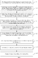
- the charging policy setting method includes:
- the plurality of core working parameters can include, but not limited to: a changing slope of the target core with a charging duration at an anode potential of a current stabilizing section corresponding to the target SOC range, a charging duration, an anode potential of the target core at a lower limit value of the target SOC range, a changing rate of the target core at an anode potential of a breaking current section of the target SOC range, and a current flowing through the target core at the lower limit value of the target SOC range.
- the plurality of core working parameters can be obtained through the following manner: where the changing slope with a charging duration at an anode potential of a current stabilizing section corresponding to the target SOC range can be obtained according to the following manner: obtaining an anode potential of a current stabilizing section corresponding to the target SOC range collected by a voltage collection module and obtaining a charging duration of the target SOC range recorded by a timer; and calculating a changing slope with a charging duration at an anode potential of a current stabilizing section corresponding to the target SOC range according to the anode potential of a current stabilizing section corresponding to the target SOC range and the charging duration of the target SOC range.
- the changing slope of the target core with a charging duration at an anode potential of a current stabilizing section corresponding to the target SOC range can be obtained through the following manner: obtaining an anode potential of the target core collected by the voltage collection module upon charging the anode potential of the target core to a lower limit value of the target SOC range when a present SOC is at the lower limit value of the target SOC range.
- the changing rate of the target core at an anode potential of a breaking current section of the target SOC range can be obtained through the following manner: obtaining a current collected by a current collection module and detecting whether the current is in a breaking current section, and if yes, obtaining an anode potential of the target core collected by the voltage collection module.
- the changing rate of the target core at an anode potential of a breaking current section of the target SOC range can be calculated according to the charging duration and the anode potential.
- the current flowing through the target core at a lower limit value of the target SOC range can be obtained through the following manner: the current flowing through the target core collected by the current collection module can be obtained when the present SOC is at the lower limit value of the target SOC range.
- values of the plurality of different core working parameters are different. It is assumed that the target charging condition includes a different SOC range and a different ambient temperature range, and values for the anode potential of the target core at a lower limit value of the target SOC range, for the changing slope of the target core with a charging duration at an anode potential of a current stabilizing section corresponding to the target SOC range and for the changing rate of the target core at an anode potential of a breaking current section of the target SOC range can be represented respectively in the following Table 1 to Table 3 under the different SOC range and the different ambient temperature range. Table 1 SOC range/ambient temperature range [T1, T2] [T2, T3] ...
- T is an ambient temperature and V is an anode potential of the target core at the lower limit value of the target SOC range.
- Table 2 SOC range/ambient temperature range [T1, T2] [T2, T3] ... [Tn, Tn-1] [SOC1, SOC2] K 1, 1 K 1, 2 ... K 1, n-1 ... ... ... ... ... [SOC (n-1), SOC(n-2)] K n-1, 1 K n-1, 2 ... K n-1, n-1
- T is an ambient temperature and K is a changing slope of the target core with a charging duration at an anode potential of a current stabilizing section corresponding to the target SOC range.
- Table 3 SOC range/ temperature [T1, T2] [T2, T3] ... [Tn, Tn-1] [SOC1, SOC2] B 1, 1 B 1, 2 ... B 1, n-1 ... ... ... ... ... [SOC (n-1), SOC (n-2)] B n-1, 1 B n-1, 2 ... B n-1, n-1
- T is an ambient temperature and B is a changing rate of the target core at an anode potential of a breaking current section of the target SOC range.
- the plurality of different core working parameters are determined upon charging at the target charging rate corresponding to the target charging condition. Therefore, the plurality of different core working parameters can be used as the reference factors for determining a maximum charging rate corresponding to each charging duration under the target charging condition.
- the target charging condition includes a plurality of charging durations
- a plurality of maximum charging rates in one-to-one correspondence to the plurality of charging durations can be determined.
- the target charging condition includes the target SOC range [SOC1, SOC2] and the target temperature range [T1, T2]
- the plurality of the charging durations under the target temperature range [T1, T2] and the target SOC range [SOC1, SOC2] include moments t1-t10.
- the maximum charging rate M1 can be determined at moment t1 and the maximum charging rate M2 is determined at moment t2, and so on, which are not limited herein.
- the target charging condition includes the target SOC range [SOC2, SOC3] and the target temperature range [T1, T2]
- the plurality of the charging durations under the target temperature range [T1, T2] and the target SOC range [SOC2, SOC3] include moments t11-t20.
- the maximum charging rate M11 can be determined at moment t11 and the maximum charging rate M12 is determined at moment t12, and so on, which are not limited herein.
- an anode potential of the target core under each charging duration is not lower than a preset cutoff anode potential when the target core is charged at the maximum charging rate. It can be understood that if an anode potential of the target core is lower than a preset cutoff anode potential, the target core will be damaged (if the target core is a core of a lithium battery, lithium plating of the core will be caused). Therefore, in a charging process, the anode potential of the target core is made not to be lower than the upper limit value of the charging rate of the preset cutoff anode potential, i.e. the maximum charging rate.
- the above target charging rate can be the maximum charging rate corresponding to the target charging condition.
- an anode potential of the target core is not lower than a preset cutoff anode potential for each charging duration corresponding to the target charging condition when the target core is charged at the maximum charging rate corresponding to the target charging condition.
- the target core under the target charging condition can be immediately charged according to the determined charging policy, thereby realizing real time determination of a charging policy and real time charging.
- the charging policy setting method includes firstly obtaining the plurality of different core working parameters upon charging of the target core under the target charging condition at the target charging rate corresponding to the target charging condition; then, determining a maximum charging rate corresponding to each charging duration under the target charging condition according to the plurality of different core working parameters; and setting a charging policy under the target charging condition according to each charging duration under the target charging condition and the maximum charging rate corresponding to each charging duration.
- the target core is charged at the maximum charging rate by satisfying a condition that an anode potential of the target core is not lower than a preset cutoff anode potential during each charging duration corresponding to the target charging condition. In this way, a fast charging speed and a high charging efficiency are ensured.
- Q is the preset cutoff anode potential
- k is the changing slope of the target core with the charging duration at the anode potential of the current stabilizing section corresponding to the target SOC range
- t is the charging duration
- V[x,y]A is the anode potential of the target core at the lower limit value of the target SOC range
- B is the changing rate of the target core at the anode potential of the breaking current section of the target SOC range
- IX is the current flowing through the target core at the lower limit value of the target SOC range
- IZ is the maximum charging rate.
- the manner for determining the target charging rate can include, but not limited to the following two manners: No. 1 manner: as shown in FIG. 2 , the following steps can be employed before S21 to determine the target charging rate.
- S31 obtaining an anode potential upon charging of a target core under a target charging condition respectively at a plurality of different preset charging rates.
- the preset charging rate of a different value corresponds to an anode potential of a different value. It is assumed that a plurality of different preset charging rates include C[1, 1], C[1, 2], C[1, n-1], the target core is charged at the preset charging rate C[1, 1] to obtain an anode potential A[1, 1]; the target core is charged at the preset charging rate C[1, 2] to obtain an anode potential A[1, 2]; and the target core is charged at the preset charging rate C[1, n-1] to obtain an anode potential A[1, n-1]. It can be seen that C[1, 1] has a corresponding relationship with A[1, 1], C[1, 2] has a corresponding relationship with A[1, 2] and C[1, n-1] has a corresponding relationship with A[1, n-1].
- Table 4 shows a corresponding relationship of a value of a preset charging rate to a value of an anode potential under a different target charging condition.
- Table 4 SOC range / temperature range Preset charging rate C / anode potential A [SOC1, SOC2] / [T1-T2] C[1, 1] C[1, 2] ... C[1, n-1] A[1, 1] A[1, 2] ... A[1, n-1] [SOC3, SOC4] / [T2-T3] C[2, 1] C[2, 2] ... C[2, n-1] A[2, 1] A[2, 2] ... A[2, n-1] ... ... ... ... ... ... ...
- S32 determining a function relationship of the anode potential under the target charging condition changing with the preset charging rates according to the plurality of different preset charging rates and the anode potential in one-to-one correspondence to the preset charging rates.
- the target charging condition includes the target SOC range [SOC1, SOC2] and the target temperature range [T1, T2]
- C[1, 1] has a corresponding relationship with A[1, 1]
- C[1, 2] has a corresponding relationship with A[1, 2]
- C[1, n-1] has a corresponding relationship with A[1, n-1].
- ⁇ C[1, 1], A[1, 1] ⁇ , ⁇ C[1, 2], A[1, 2] ⁇ , ⁇ C[1, n-1] and A[1, n-1] ⁇ can be fit to obtain a fitting straight line, where the fitting straight line can represent a function relationship of the anode potential under the target charging condition changing with the preset charging rates.
- S33 determining a charging rate corresponding to a critical value of a set anode potential as the target charging rate according to the function relationship of the anode potential changing with the preset charging rates.
- the critical value of the set anode potential is the lowest anode potential at which the target core is not damaged under the target charging condition.
- the set anode potential can be brought into the function relationship of the anode potential under the target charging condition changing with the preset charging rates to obtain a target charging rate. It can be understood that the target charging rate determined at this time is the maximum charging rate at which the target core is not damaged under the target charging condition.
- the parameter finally needing to be obtained is to determine a maximum charging rate corresponding to each charging duration under the target charging condition. Therefore, at the charging rate (i.e. the maximum charging rate under the target charging condition) corresponding to a critical value of an anode potential under the target charging condition, the obtained plurality of different core working parameters are used for determining a higher reliability of the maximum charging rate corresponding to each charging duration under the target charging condition.
- the target charging rate can also be pre-configured by a manufacturer according to actual requirements.
- the configured target charging rate is smaller than the maximum charging rate under the target charging condition and a difference value between the configured target charging rate and the maximum charging rate is smaller than a preset threshold. It can be understood that the probability of causing a damage to the target core upon being charged becomes small when the configured target charging rate is smaller than the maximum charging rate under the target charging condition.
- the obtained plurality of different core working parameters can be used for determining a higher reliability of the maximum charging rate corresponding to each charging duration under the target charging condition when the difference value between the configured target charging rate and the maximum charging rate is smaller than the preset threshold.
- embodiments of the present application further provide a charging method, also applied to an electronic device powered with a target core.
- the electronic device can be, but not limited to a smart phone, a tablet PC, an electric automobile and other electronic devices powered with a battery pack.
- a display interface of the electronic device is lighted on and the display interface includes an icon for indicating display SOC.
- the method includes:
- S41 determining a target charging condition of a target core when the target core is in a charging state.
- the target charging condition includes a different SOC range and a different ambient temperature range
- an ambient temperature around the target core and the SOC of the target core are detected.
- the target charging condition of the target core is determined.
- the ambient temperature around the target core can be collected through a temperature sensor, and parameters like a present temperature, working conditions, and an available electric quantity range of the target core are collected.
- the SOC of the target core is calculated according to the temperature, working conditions, and the available electric quantity range of the target core.
- one-to-one correspondence relationship between the target charging condition and the charging policy is pre-stored.
- the charging policy can be found according to the target charging condition after determining the target charging condition of the target core.
- the charging policy includes each charging duration under the target charging condition and a maximum charging rate corresponding to each charging duration.
- the maximum charging rate corresponding to each charging duration under the target charging condition is determined according to the plurality of different core working parameters.
- the specific charging manner can involve charging the target core at the maximum charging rate corresponding to the charging duration for each charging duration under the target charging condition. That is, the target core is charged at the maximum charging rate by satisfying a condition that the anode potential of the target core is not lower than the preset cutoff anode potential during each charging duration corresponding to the target charging condition. In this way, a fast charging speed and a high charging efficiency are ensured.
- the present application further provides a charging policy setting apparatus 50, applied to an electronic device powered with a target core.
- the electronic device includes a battery management system (BMS) and the method for determining display SOC of the battery pack can be specifically applied to the BMS.
- BMS battery management system
- the electronic device can be, but not limited to a smart phone, a tablet PC, an electric automobile and other electronic devices powered with a battery pack.
- the charging policy setting apparatus 50 of the battery pack provided by embodiments of the present application, the basic principles thereof and the technical effects produced thereby are the same as those of the above embodiments. For concise descriptions, reference can be made to the corresponding contents in the above embodiments for a part which is not mentioned in the embodiment.
- the apparatus 50 includes a parameter obtaining unit 51, a rate determining unit 52, and a policy setting unit 53, where the parameter obtaining unit 51 is used for obtaining a plurality of different core working parameters upon charging of a target core under a target charging condition at a target charging rate corresponding to the target charging condition, where the target charging condition includes a target SOC range.
- the plurality of different core working parameters can include, but not limited to: a preset cutoff anode potential, an anode potential of the target core at a lower limit value of the target SOC range, a current flowing through the target core at a lower limit value of the target SOC range, a changing rate of the target core at an anode potential of a breaking current section of the target SOC range, and a changing slope of the target core with a charging duration at an anode potential of a current stabilizing section corresponding to the target SOC range.
- the rate determining unit 52 is used for determining a maximum charging rate corresponding to each charging duration under the target charging condition according to the plurality of different core working parameters, where an anode potential of the target core is not lower than a preset cutoff anode potential when the target core is charged at the maximum charging rate.
- Q is a preset cutoff anode potential
- k is a changing slope of the target core with a charging duration at an anode potential of a current stabilizing section corresponding to the target SOC range
- t is a charging duration
- V[x,y]A is an anode potential of the target core at a lower limit value of the target SOC range
- B is a changing rate of the target core at an anode potential of a breaking current section of the target SOC range
- IX is a current flowing through the target core at a lower limit value of the target SOC range
- IZ is a maximum charging rate.
- the policy setting unit 53 is used for setting a charging policy under the target charging condition according to each charging duration under the target charging condition and the maximum charging rate corresponding to each charging duration.
- determining the target charging rate can be implemented through the following unit: the parameter obtaining unit 51 is further used for obtaining an anode potential upon charging of a target core under a target charging condition respectively at a plurality of different preset charging rates.
- the apparatus 50 can further include: a function relationship determining unit for determining a function relationship of the anode potential under the target charging condition changing with the preset charging rates according to the plurality of different preset charging rates and the anode potential in one-to-one correspondence to the preset charging rates.
- the rate determining unit 53 is further used for determining a charging rate corresponding to a critical value of a set anode potential as the target charging rate according to the function relationship of the anode potential changing with the preset charging rates.
- the target charging rate is pre-configured.
- the apparatus 50 can further include: a charging unit for charging the target core under the target charging condition according to the charging policy.
- the present application further provides a charging apparatus 60, applied to an electronic device powered with a target core.
- the electronic device includes a battery management system (BMS) and the method for determining display SOC of the battery pack can be specifically applied to the BMS.
- BMS battery management system
- the electronic device can be, but not limited to a smart phone, a tablet PC, an electric automobile and other electronic devices powered with a battery pack.
- the apparatus 60 includes a condition determining unit 61, a policy determining unit 62 and a charging unit 63, where
- the charging unit 63 is used for charging the target core according to the charging policy.
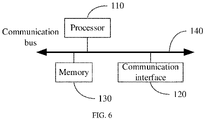
- FIG. 6 is a structural diagram of an electronic device for performing a charging policy setting method or a charging method provided by embodiments of the present application.
- the electronic device can include at least one processor 110 such as a CPU, at least one communication interface 120, at least one memory 130 and at least one communications bus 140.
- the communication bus 140 is used for implementing a direct connection communication between these components.
- the communication interface 120 of the device in embodiments of the present application is used for performing signaling or data communication with another node device.
- the memory 130 can be a high-speed RAM memory, or can also be a non-volatile memory (non-volatile memory), for example, at least one magnetic disk memory.
- the memory 130 can also be at least one storage apparatus located far away from the processor.
- the memory 130 stores a computer-readable instruction, and when the computer-readable instruction is executed by the processor 110, the electronic device performs the process of the method shown in FIG. 2 and FIG. 4 .
- FIG. 6 is only illustrative and the electronic device can further include more or less components shown in FIG. 6 or have a different configuration shown in FIG. 6 .
- Each component shown in FIG. 6 can be implemented with a hardware, a software or a combination thereof.
- the apparatus can be a module, a program section or a code on the electronic device. It should be understood that the apparatus corresponds to the method embodiment in FIG. 2 and FIG. 4 and is capable of performing each step involved in the method embodiment in FIG. 2 and FIG. 4 . Regarding specific functions of the apparatus, reference can be made to descriptions in the previous text. In order to avoid repetition, detailed descriptions are omitted herein.
- Embodiments of the present application provide a readable storage medium storing a computer program thereon, and when the computer program is executed by a processor, the process of the method performed by the electronic device in the method embodiment shown in FIG. 2 and FIG. 4 is performed.
- the embodiment discloses a computer program product, the computer program product includes a computer program stored on a non-transient computer-readable storage medium.
- the computer program includes a program instruction, where when the program instruction is performed by a computer, the computer is capable of performing the method provided in the above method embodiments.
- obtaining a plurality of different core working parameters upon charging of a target core under a target charging condition at a target charging rate corresponding to the target charging condition, where the target charging condition includes a target SOC range; determining a maximum charging rate corresponding to each charging duration under the target charging condition according to the plurality of different core working parameters, where an anode potential of the target core is not lower than a preset cutoff anode potential when the target core is charged at the maximum charging rate; and setting a charging policy under the target charging condition according to each charging duration under the target charging condition and the maximum charging rate corresponding to each charging duration, can be performed.
- the disclosed apparatus and method may be implemented in other manners.
- the described apparatus embodiment is merely an example.
- the unit division is merely logical function division and may be other division in actual implementation.
- a plurality of units or components may be combined or integrated into another system, or some features may be ignored or may not be performed.
- the displayed or discussed mutual couplings or direct couplings or communication connections may be implemented by using some interfaces.
- the indirect couplings or communication connections between the apparatuses or units may be implemented in electronic, mechanical, or other forms.
- the units described as separate parts may or may not be physically separated, and the parts displayed as units may or may not be physical units, i.e. may be located in one position, or may be distributed on a plurality of network units. Some or all of the units may be selected based on actual requirements to achieve the objectives of the solutions of the embodiments.
Landscapes
- Engineering & Computer Science (AREA)
- Power Engineering (AREA)
- Manufacturing & Machinery (AREA)
- Chemical & Material Sciences (AREA)
- Chemical Kinetics & Catalysis (AREA)
- Electrochemistry (AREA)
- General Chemical & Material Sciences (AREA)
- Charge And Discharge Circuits For Batteries Or The Like (AREA)
- Secondary Cells (AREA)
Abstract
Description
- The present application relates to the field of batteries and specifically, relates to a charging policy setting method and apparatus.
- At present, a rechargeable battery has been widely applied to electronic devices of each field (such as an electric vehicle, a mobile phone and a handheld computer etc.), as a power supply source of these electronic devices. When electrical energy stored by the rechargeable battery exhausts, a user can charge the rechargeable battery to facilitate subsequent continuation of these electronic devices. If a charging speed of the rechargeable battery is faster, more time will be saved for the user and the user experience will be better as well. However, if a charging speed of the rechargeable battery is excessively fast, the rechargeable battery is possibly damaged (such as causing lithium plating of a lithium battery). Therefore, how to increase the charging speed of the rechargeable battery as far as possible without causing any damage to the rechargeable battery is a problem to be solved.
- The objective of embodiments of the present application is to provide a charging policy setting method and apparatus for improving the charging speed of the rechargeable battery.
- According to a first aspect, embodiments of the present application provide a charging policy setting method, the method including:
obtaining a plurality of different core working parameters upon charging of a target core under a target charging condition at a target charging rate corresponding to the target charging condition; determining a maximum charging rate corresponding to each charging duration under the target charging condition according to the plurality of different core working parameters; and setting a charging policy under the target charging condition according to each charging duration under the target charging condition and the maximum charging rate corresponding to each charging duration. - The charging policy setting method includes firstly obtaining a plurality of different core working parameters upon charging of a target core under a target charging condition at a target charging rate corresponding to the target charging condition; then, determining a maximum charging rate corresponding to each charging duration under the target charging condition according to the plurality of different core working parameters; and setting a charging policy under the target charging condition according to each charging duration under the target charging condition and the maximum charging rate corresponding to each charging duration. Thus, when the target core is charged at the set charging policy under the target charging condition, for each charging duration under the target charging condition, the target core is charged at the maximum charging rate corresponding to the charging duration. That is, the target core is charged at the maximum charging rate by satisfying a condition that an anode potential of the target core is not lower than a preset cutoff anode potential during each charging duration corresponding to the target charging condition. In this way, a fast charging speed and a high charging efficiency are ensured.
- In a possible design solution, where the target charging condition includes a target SOC range and the plurality of different core working parameters can include: a preset cutoff anode potential, an anode potential of the target core at a lower limit value of the target SOC range, a current flowing through the target core at the lower limit value of the target SOC range, a changing rate of the target core at an anode potential of a breaking current section of the target SOC range, and a changing slope of the target core with a charging duration at an anode potential of a current stabilizing section corresponding to the target SOC range.
- Further, the determining a maximum charging rate corresponding to each charging duration under the target charging condition according to the plurality of different core working parameters can include determining a maximum charging rate corresponding to each charging duration under the target charging condition according to a formula Iz=(Q-kt-V[x,y]A)/B+Ix, where Q is the preset cutoff anode potential, k is the changing slope of the target core with the charging duration at the anode potential of the current stabilizing section corresponding to the target SOC range, t is the charging duration, V[x,y]A is the anode potential of the target core at the lower limit value of the target SOC range, B is the changing rate of the target core at the anode potential of the breaking current section of the target SOC range, Ix is the current flowing through the target core at the lower limit value of the target SOC range and Iz is the maximum charging rate.
- In a possible design solution, before the obtaining the plurality of different core working parameters upon charging of the target core under the target charging condition at the target charging rate corresponding to the target charging condition, the method further includes: obtaining an anode potential upon charging of a target core under the target charging condition respectively at a plurality of different preset charging rates; determining a function relationship of the anode potential under the target charging condition changing with the preset charging rates according to the plurality of different preset charging rates and the anode potential in one-to-one correspondence to the preset charging rates; and determining a charging rate corresponding to a critical value of a set anode potential as the target charging rate according to the function relationship of the anode potential changing with the preset charging rates.
- The parameter needing to be obtained is to determine a maximum charging rate corresponding to each charging duration under the target charging condition. Therefore, at the charging rate (i.e. the maximum charging rate under the target charging condition) corresponding to a critical value of an anode potential under the target charging condition, the obtained plurality of different core working parameters are used for determining a higher reliability of the maximum charging rate corresponding to each charging duration under the target charging condition.
- Alternatively, in another possible design solution, the target charging rate is pre-configured.
- In a possible design solution, after the setting a charging policy under the target charging condition according to each charging duration under the target charging condition and the maximum charging rate corresponding to the each charging duration, the method further includes: charging the target core under the target charging condition according to the charging policy.
- According to a second aspect, embodiments of the present application further provide a charging method, the method includes:
- determining a target charging condition of a target core when the target core is in a charging state;
- determining a charging policy according to the target charging condition, where the charging policy includes each charging duration under the target charging condition and a maximum charging rate corresponding to the each charging duration; and
- charging the target core according to the charging policy.
- According to a third aspect, the present application further provides a charging policy setting apparatus, the apparatus includes:
- a parameter obtaining unit, configured to obtain a plurality of different core working parameters upon charging of a target core under a target charging condition at a target charging rate corresponding to the target charging condition, where the target charging condition includes a target SOC range;
- a rate determining unit, configured to determine a maximum charging rate corresponding to each charging duration under the target charging condition according to the plurality of different core working parameters, where an anode potential of the target core is not lower than a preset cutoff anode potential when the target core is charged at the maximum charging rate; and
- a policy setting unit, configured to set a charging policy under the target charging condition according to each charging duration under the target charging condition and the maximum charging rate corresponding to the each charging duration.
- According to a fourth aspect, the present application further provides a charging apparatus, the apparatus includes:
- a condition determining unit, configured to determine a target charging condition of a target core when the target core is in a charging state;
- a policy determining unit, configured to determine a charging policy according to the target charging condition, where the charging policy includes each charging duration under the target charging condition and a maximum charging rate corresponding to the each charging duration; and
- a charging unit, configured to charge the target core according to the charging policy.
- According to a fifth aspect, embodiments of the present application provide an electronic device, includes a processor and a memory, where the memory stores a computer-readable instruction, and when the computer-readable instruction is executed by the processor, steps of the method provided in the first aspect are operated.
- According to a sixth aspect, embodiments of the present application provide a readable storage medium storing a computer program thereon, where when the computer program is executed by a processor, steps of the method provided in the first aspect are operated.
- To describe the technical solutions in the embodiments of the present application more clearly, the following briefly describes the accompanying drawings required for describing the embodiments of the present application. It should be understood that the following accompanying drawings merely show some embodiments of the present application and thus should not be regarded as limitation to the scope thereof. A person of ordinary skill in the art may derive other drawings from these accompanying drawings without creative efforts.
-
FIG. 1 is a flowchart 1 of a charging policy setting method provided by embodiments of the present application; -
FIG. 2 is a flowchart 2 of a charging policy setting method provided by embodiments of the present application; -
FIG. 3 is a flowchart of a charging method provided by embodiments of the present application; -
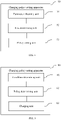
FIG. 4 is a block diagram of a functional module of a charging policy setting apparatus provided by embodiments of the present application; -
FIG. 5 is a block diagram of a functional module of a charging apparatus provided by embodiments of the present application; and -
FIG. 6 is a structural block diagram of an electronic device provided by embodiments of the present application. - SOC: state of charge SOC (state of charge, SOC), is a ratio of a residual capacity after a storage battery is used or not used for a period to a capacity of its full-charging stage. A value thereof ranges between 0 and 1. When SOC=0, it means full discharging of the battery and when SOC=1, it means full charging of the battery.
- The following clearly and completely describes the technical solutions in the embodiments of the present application with reference to the accompanying drawings in the embodiments of the present application.
- At present the fast charging manner for the rechargeable battery involves: determining a cutoff anode potential of each SOC range in a plurality of SOC ranges of a battery, and determining a charging rate according to a cutoff anode potential corresponding to each SOC range. Further, the rechargeable battery can be charged according to the charging rate corresponding to each SOC range. However, the above charging speed for the rechargeable battery is still low.
- Embodiments of the present application provide a charging policy setting method, applied to an electronic device powered with a target core. Where the target core can be, but not limited to an iron phosphate lithium core, a nickel-cobalt-lithium manganese oxide core and other rechargeable cores. Specifically, an electronic device includes a battery management system (Battery Management System, BMS) and the display SOC of the target core can be determined to be implemented by the BMS. Where the electronic device can be, but not limited to a smart phone, a tablet PC, an electric automobile and other electronic devices powered with a battery pack. As shown in
FIG. 1 , the charging policy setting method includes: - S21: obtaining a plurality of different core working parameters upon charging of a target core under a target charging condition at a target charging rate corresponding to the target charging condition;
- where the target charging condition includes a target SOC range. In addition, in some examples, the target charging condition can further include an ambient temperature range, a battery temperature range and the like, which are not limited herein.
- In some embodiments, the plurality of core working parameters can include, but not limited to: a changing slope of the target core with a charging duration at an anode potential of a current stabilizing section corresponding to the target SOC range, a charging duration, an anode potential of the target core at a lower limit value of the target SOC range, a changing rate of the target core at an anode potential of a breaking current section of the target SOC range, and a current flowing through the target core at the lower limit value of the target SOC range.
- Where, the plurality of core working parameters can be obtained through the following manner:
where the changing slope with a charging duration at an anode potential of a current stabilizing section corresponding to the target SOC range can be obtained according to the following manner: obtaining an anode potential of a current stabilizing section corresponding to the target SOC range collected by a voltage collection module and obtaining a charging duration of the target SOC range recorded by a timer; and calculating a changing slope with a charging duration at an anode potential of a current stabilizing section corresponding to the target SOC range according to the anode potential of a current stabilizing section corresponding to the target SOC range and the charging duration of the target SOC range. - The changing slope of the target core with a charging duration at an anode potential of a current stabilizing section corresponding to the target SOC range can be obtained through the following manner: obtaining an anode potential of the target core collected by the voltage collection module upon charging the anode potential of the target core to a lower limit value of the target SOC range when a present SOC is at the lower limit value of the target SOC range.
- The changing rate of the target core at an anode potential of a breaking current section of the target SOC range can be obtained through the following manner: obtaining a current collected by a current collection module and detecting whether the current is in a breaking current section, and if yes, obtaining an anode potential of the target core collected by the voltage collection module. The changing rate of the target core at an anode potential of a breaking current section of the target SOC range can be calculated according to the charging duration and the anode potential.
- The current flowing through the target core at a lower limit value of the target SOC range can be obtained through the following manner: the current flowing through the target core collected by the current collection module can be obtained when the present SOC is at the lower limit value of the target SOC range.
- In some embodiments, under different target charging conditions, values of the plurality of different core working parameters are different. It is assumed that the target charging condition includes a different SOC range and a different ambient temperature range, and values for the anode potential of the target core at a lower limit value of the target SOC range, for the changing slope of the target core with a charging duration at an anode potential of a current stabilizing section corresponding to the target SOC range and for the changing rate of the target core at an anode potential of a breaking current section of the target SOC range can be represented respectively in the following Table 1 to Table 3 under the different SOC range and the different ambient temperature range.
Table 1 SOC range/ambient temperature range [T1, T2] [T2, T3] ... [Tn-1, Tn] [SOC1, SOC2] V1, 1 V1, 2 ... V1, n-1 ... ... ... ... ... [SOC (n-1), SOC (n-2)] Vn-1, n Vn-1, 2 ... Vn-1, n-1 - It can be understood that in Table 1, T is an ambient temperature and V is an anode potential of the target core at the lower limit value of the target SOC range.
Table 2 SOC range/ambient temperature range [T1, T2] [T2, T3] ... [Tn, Tn-1] [SOC1, SOC2] K1, 1 K1, 2 ... K1, n-1 ... ... ... ... ... [SOC (n-1), SOC(n-2)] Kn-1, 1 Kn-1, 2 ... Kn-1, n-1 - It can be understood that in Table 2, T is an ambient temperature and K is a changing slope of the target core with a charging duration at an anode potential of a current stabilizing section corresponding to the target SOC range.
Table 3 SOC range/ temperature [T1, T2] [T2, T3] ... [Tn, Tn-1] [SOC1, SOC2] B1, 1 B1, 2 ... B 1, n-1 ... ... ... ... ... [SOC (n-1), SOC (n-2)] Bn-1, 1 Bn-1, 2 ... Bn-1, n-1 - It can be understood that in Table 3, T is an ambient temperature and B is a changing rate of the target core at an anode potential of a breaking current section of the target SOC range.
- S22: determining a maximum charging rate corresponding to each charging duration under the target charging condition according to the plurality of different core working parameters.
- The plurality of different core working parameters are determined upon charging at the target charging rate corresponding to the target charging condition. Therefore, the plurality of different core working parameters can be used as the reference factors for determining a maximum charging rate corresponding to each charging duration under the target charging condition.
- It can be understood that when the target charging condition includes a plurality of charging durations, a plurality of maximum charging rates in one-to-one correspondence to the plurality of charging durations can be determined. For example, when the target charging condition includes the target SOC range [SOC1, SOC2] and the target temperature range [T1, T2], the plurality of the charging durations under the target temperature range [T1, T2] and the target SOC range [SOC1, SOC2] include moments t1-t10. In this way, the maximum charging rate M1 can be determined at moment t1 and the maximum charging rate M2 is determined at moment t2, and so on, which are not limited herein. For example again, when the target charging condition includes the target SOC range [SOC2, SOC3] and the target temperature range [T1, T2], the plurality of the charging durations under the target temperature range [T1, T2] and the target SOC range [SOC2, SOC3] include moments t11-t20. In this way, the maximum charging rate M11 can be determined at moment t11 and the maximum charging rate M12 is determined at moment t12, and so on, which are not limited herein.
- Where an anode potential of the target core under each charging duration is not lower than a preset cutoff anode potential when the target core is charged at the maximum charging rate. It can be understood that if an anode potential of the target core is lower than a preset cutoff anode potential, the target core will be damaged (if the target core is a core of a lithium battery, lithium plating of the core will be caused). Therefore, in a charging process, the anode potential of the target core is made not to be lower than the upper limit value of the charging rate of the preset cutoff anode potential, i.e. the maximum charging rate.
- It should be noted that the above target charging rate can be the maximum charging rate corresponding to the target charging condition. Where an anode potential of the target core is not lower than a preset cutoff anode potential for each charging duration corresponding to the target charging condition when the target core is charged at the maximum charging rate corresponding to the target charging condition.
- S23: setting a charging policy under the target charging condition according to each charging duration under the target charging condition and the maximum charging rate corresponding to the each charging duration.
- Based on the example in S22, the charging policy set under the target charging condition can be: when the target charging condition includes the target SOC range [SOC1, SOC2] and the target temperature range [T1, T2], setting charging at the maximum charging rate M1 during moment t1, charging at the maximum charging rate M2 during moment t2 ...... charging at the maximum charging rate M10 during moment t10; and when the target charging condition includes the target SOC range [SOC2, SOC3] and the target temperature range [T1, T2], setting charging at the maximum charging rate M11 during moment t11, charging at the maximum charging rate M12 during moment t12 ...... charging at the maximum charging rate M20 during moment t20.
- After determining the charging policy, the target core under the target charging condition can be immediately charged according to the determined charging policy, thereby realizing real time determination of a charging policy and real time charging.
- The charging policy setting method includes firstly obtaining the plurality of different core working parameters upon charging of the target core under the target charging condition at the target charging rate corresponding to the target charging condition; then, determining a maximum charging rate corresponding to each charging duration under the target charging condition according to the plurality of different core working parameters; and setting a charging policy under the target charging condition according to each charging duration under the target charging condition and the maximum charging rate corresponding to each charging duration. Thus, when the target core is charged at the set charging policy under the target charging condition, for each charging duration under the target charging condition, the target core is charged at the maximum charging rate corresponding to the charging duration. That is, the target core is charged at the maximum charging rate by satisfying a condition that an anode potential of the target core is not lower than a preset cutoff anode potential during each charging duration corresponding to the target charging condition. In this way, a fast charging speed and a high charging efficiency are ensured.
- In some embodiments, when the plurality of core working parameters include: a changing slope of the target core with a charging duration at an anode potential of a current stabilizing section corresponding to the target SOC range, a charging duration, an anode potential of the target core at a lower limit value of the target SOC range, a changing rate of the target core at an anode potential of a breaking current section of the target SOC range, a current flowing through the target core at a lower limit value of the target SOC range and the maximum charging rate, the above S22 can specifically be implemented according to the following manner: determining a maximum charging rate corresponding to each charging duration under the target charging condition according to a formula IZ=(Q-kt-V[x,y]A)/B+IX.
- Where Q is the preset cutoff anode potential, k is the changing slope of the target core with the charging duration at the anode potential of the current stabilizing section corresponding to the target SOC range, t is the charging duration, V[x,y]A is the anode potential of the target core at the lower limit value of the target SOC range, B is the changing rate of the target core at the anode potential of the breaking current section of the target SOC range, IX is the current flowing through the target core at the lower limit value of the target SOC range and IZ is the maximum charging rate.
- In some embodiments, the manner for determining the target charging rate can include, but not limited to the following two manners:
No. 1 manner: as shown inFIG. 2 , the following steps can be employed before S21 to determine the target charging rate. - S31: obtaining an anode potential upon charging of a target core under a target charging condition respectively at a plurality of different preset charging rates.
- It can be understood that the preset charging rate of a different value corresponds to an anode potential of a different value. It is assumed that a plurality of different preset charging rates include C[1, 1], C[1, 2], C[1, n-1], the target core is charged at the preset charging rate C[1, 1] to obtain an anode potential A[1, 1]; the target core is charged at the preset charging rate C[1, 2] to obtain an anode potential A[1, 2]; and the target core is charged at the preset charging rate C[1, n-1] to obtain an anode potential A[1, n-1]. It can be seen that C[1, 1] has a corresponding relationship with A[1, 1], C[1, 2] has a corresponding relationship with A[1, 2] and C[1, n-1] has a corresponding relationship with A[1, n-1].
- As shown in the following Table 4, Table 4 shows a corresponding relationship of a value of a preset charging rate to a value of an anode potential under a different target charging condition.
Table 4 SOC range / temperature range Preset charging rate C / anode potential A [SOC1, SOC2] / [T1-T2] C[1, 1] C[1, 2] ... C[1, n-1] A[1, 1] A[1, 2] ... A[1, n-1] [SOC3, SOC4] / [T2-T3] C[2, 1] C[2, 2] ... C[2, n-1] A[2, 1] A[2, 2] ... A[2, n-1] ... ... ... ... ... [SOC(n-2), SOC(n-2)] / [T1-T2] C[n-2, 1] C[n-2, 2] ... C[n-2, n-1] A[n-2, 1] A[n-2, 2] ... A[n-2, n-1] [SOC(n-1), SOC(n-2)] / [Tn-1-Tn] C[n-1, 1] C[n-1, 2] ... C[n-1, n-1] A[n-1, 1] A[n-1, 2] ... A[n-1, n-1] - S32: determining a function relationship of the anode potential under the target charging condition changing with the preset charging rates according to the plurality of different preset charging rates and the anode potential in one-to-one correspondence to the preset charging rates.
- When the target charging condition includes the target SOC range [SOC1, SOC2] and the target temperature range [T1, T2], based on S31, C[1, 1] has a corresponding relationship with A[1, 1], C[1, 2] has a corresponding relationship with A[1, 2] and C[1, n-1] has a corresponding relationship with A[1, n-1]. Further, {C[1, 1], A[1, 1]}, {C[1, 2], A[1, 2]}, {C[1, n-1] and A[1, n-1]} can be fit to obtain a fitting straight line, where the fitting straight line can represent a function relationship of the anode potential under the target charging condition changing with the preset charging rates.
- S33: determining a charging rate corresponding to a critical value of a set anode potential as the target charging rate according to the function relationship of the anode potential changing with the preset charging rates.
- Where when the critical value of the set anode potential is the lowest anode potential at which the target core is not damaged under the target charging condition. The set anode potential can be brought into the function relationship of the anode potential under the target charging condition changing with the preset charging rates to obtain a target charging rate. It can be understood that the target charging rate determined at this time is the maximum charging rate at which the target core is not damaged under the target charging condition.
- It can be understood that in embodiments of the present application, the parameter finally needing to be obtained is to determine a maximum charging rate corresponding to each charging duration under the target charging condition. Therefore, at the charging rate (i.e. the maximum charging rate under the target charging condition) corresponding to a critical value of an anode potential under the target charging condition, the obtained plurality of different core working parameters are used for determining a higher reliability of the maximum charging rate corresponding to each charging duration under the target charging condition.
- In some other embodiments, the target charging rate can also be pre-configured by a manufacturer according to actual requirements. For example, the configured target charging rate is smaller than the maximum charging rate under the target charging condition and a difference value between the configured target charging rate and the maximum charging rate is smaller than a preset threshold. It can be understood that the probability of causing a damage to the target core upon being charged becomes small when the configured target charging rate is smaller than the maximum charging rate under the target charging condition. In addition, the obtained plurality of different core working parameters can be used for determining a higher reliability of the maximum charging rate corresponding to each charging duration under the target charging condition when the difference value between the configured target charging rate and the maximum charging rate is smaller than the preset threshold.
- Please referring to
FIG. 3 , embodiments of the present application further provide a charging method, also applied to an electronic device powered with a target core. Where the electronic device can be, but not limited to a smart phone, a tablet PC, an electric automobile and other electronic devices powered with a battery pack. When the electronic device is in a working state, a display interface of the electronic device is lighted on and the display interface includes an icon for indicating display SOC. As shown inFIG. 4 , the method includes: - S41: determining a target charging condition of a target core when the target core is in a charging state.
- For example, when the target charging condition includes a different SOC range and a different ambient temperature range, an ambient temperature around the target core and the SOC of the target core are detected. Further, the target charging condition of the target core is determined. Specifically, the ambient temperature around the target core can be collected through a temperature sensor, and parameters like a present temperature, working conditions, and an available electric quantity range of the target core are collected. The SOC of the target core is calculated according to the temperature, working conditions, and the available electric quantity range of the target core.
- S42: determining a charging policy according to the target charging condition.
- Specifically, one-to-one correspondence relationship between the target charging condition and the charging policy is pre-stored. The charging policy can be found according to the target charging condition after determining the target charging condition of the target core.
- Where the charging policy includes each charging duration under the target charging condition and a maximum charging rate corresponding to each charging duration. The maximum charging rate corresponding to each charging duration under the target charging condition is determined according to the plurality of different core working parameters. Regarding the specific manner for determination, reference can be made to the introduction of S21 to S22 in the above embodiments, which is not described in details any longer herein.
- S43: charging the target core according to the charging policy.
- The specific charging manner can involve charging the target core at the maximum charging rate corresponding to the charging duration for each charging duration under the target charging condition. That is, the target core is charged at the maximum charging rate by satisfying a condition that the anode potential of the target core is not lower than the preset cutoff anode potential during each charging duration corresponding to the target charging condition. In this way, a fast charging speed and a high charging efficiency are ensured.
- Please referring to
FIG. 4 , the present application further provides a chargingpolicy setting apparatus 50, applied to an electronic device powered with a target core. Specifically, the electronic device includes a battery management system (BMS) and the method for determining display SOC of the battery pack can be specifically applied to the BMS. Where the electronic device can be, but not limited to a smart phone, a tablet PC, an electric automobile and other electronic devices powered with a battery pack. It should be noted that regarding the chargingpolicy setting apparatus 50 of the battery pack provided by embodiments of the present application, the basic principles thereof and the technical effects produced thereby are the same as those of the above embodiments. For concise descriptions, reference can be made to the corresponding contents in the above embodiments for a part which is not mentioned in the embodiment. Theapparatus 50 includes aparameter obtaining unit 51, arate determining unit 52, and apolicy setting unit 53, where
theparameter obtaining unit 51 is used for obtaining a plurality of different core working parameters upon charging of a target core under a target charging condition at a target charging rate corresponding to the target charging condition, where the target charging condition includes a target SOC range. - Where the plurality of different core working parameters can include, but not limited to: a preset cutoff anode potential, an anode potential of the target core at a lower limit value of the target SOC range, a current flowing through the target core at a lower limit value of the target SOC range, a changing rate of the target core at an anode potential of a breaking current section of the target SOC range, and a changing slope of the target core with a charging duration at an anode potential of a current stabilizing section corresponding to the target SOC range.
- The
rate determining unit 52 is used for determining a maximum charging rate corresponding to each charging duration under the target charging condition according to the plurality of different core working parameters, where an anode potential of the target core is not lower than a preset cutoff anode potential when the target core is charged at the maximum charging rate. - In an alternative implementation, the
rate determining unit 52 can be specifically used for determining a maximum charging rate corresponding to each charging duration under the target charging condition according to the formula Iz= (Q-kt-V [x, y] A)/B+Ix. Where Q is a preset cutoff anode potential, k is a changing slope of the target core with a charging duration at an anode potential of a current stabilizing section corresponding to the target SOC range, t is a charging duration, V[x,y]A is an anode potential of the target core at a lower limit value of the target SOC range, B is a changing rate of the target core at an anode potential of a breaking current section of the target SOC range, IX is a current flowing through the target core at a lower limit value of the target SOC range and IZ is a maximum charging rate. - The
policy setting unit 53 is used for setting a charging policy under the target charging condition according to each charging duration under the target charging condition and the maximum charging rate corresponding to each charging duration. - In some embodiments, determining the target charging rate can be implemented through the following unit:
theparameter obtaining unit 51 is further used for obtaining an anode potential upon charging of a target core under a target charging condition respectively at a plurality of different preset charging rates. - The
apparatus 50 can further include: a function relationship determining unit for determining a function relationship of the anode potential under the target charging condition changing with the preset charging rates according to the plurality of different preset charging rates and the anode potential in one-to-one correspondence to the preset charging rates. - The
rate determining unit 53 is further used for determining a charging rate corresponding to a critical value of a set anode potential as the target charging rate according to the function relationship of the anode potential changing with the preset charging rates. - In some other embodiments, the target charging rate is pre-configured.
- In some embodiments, the
apparatus 50 can further include:
a charging unit for charging the target core under the target charging condition according to the charging policy. - Please referring to
FIG. 5 , the present application further provides a chargingapparatus 60, applied to an electronic device powered with a target core. Specifically, the electronic device includes a battery management system (BMS) and the method for determining display SOC of the battery pack can be specifically applied to the BMS. Where the electronic device can be, but not limited to a smart phone, a tablet PC, an electric automobile and other electronic devices powered with a battery pack. Theapparatus 60 includes acondition determining unit 61, apolicy determining unit 62 and a chargingunit 63, where - the
condition determining unit 61 is used for determining a target charging condition of a target core when the target core is in a charging state; - the
policy determining unit 62 is used for determining a charging policy according to the target charging condition; - Where the charging policy includes each charging duration under the target charging condition and a maximum charging rate corresponding to each charging duration.
the chargingunit 63 is used for charging the target core according to the charging policy. - The defects existing in the solutions of the prior art are the results obtained by practice and careful study of the inventor. Therefore, the discovery process of the above problem and the solutions proposed for the above problem in embodiments of the present invention in the following text should be the contributions made by the inventor to the present invention in a process of the present invention.
- Please referring to
FIG. 6, FIG. 6 is a structural diagram of an electronic device for performing a charging policy setting method or a charging method provided by embodiments of the present application. The electronic device can include at least oneprocessor 110 such as a CPU, at least onecommunication interface 120, at least onememory 130 and at least onecommunications bus 140. Where, thecommunication bus 140 is used for implementing a direct connection communication between these components. Where, thecommunication interface 120 of the device in embodiments of the present application is used for performing signaling or data communication with another node device. Thememory 130 can be a high-speed RAM memory, or can also be a non-volatile memory (non-volatile memory), for example, at least one magnetic disk memory. Optionally, thememory 130 can also be at least one storage apparatus located far away from the processor. Thememory 130 stores a computer-readable instruction, and when the computer-readable instruction is executed by theprocessor 110, the electronic device performs the process of the method shown inFIG. 2 andFIG. 4 . - It can be understood that the structure shown in
FIG. 6 is only illustrative and the electronic device can further include more or less components shown inFIG. 6 or have a different configuration shown inFIG. 6 . Each component shown inFIG. 6 can be implemented with a hardware, a software or a combination thereof. - The apparatus can be a module, a program section or a code on the electronic device. It should be understood that the apparatus corresponds to the method embodiment in
FIG. 2 andFIG. 4 and is capable of performing each step involved in the method embodiment inFIG. 2 andFIG. 4 . Regarding specific functions of the apparatus, reference can be made to descriptions in the previous text. In order to avoid repetition, detailed descriptions are omitted herein. - It should be noted that a person skilled in the art can clearly understand that for convenient and concise descriptions, reference can be made to a corresponding process in the method embodiment regarding the specific working process of the system and apparatus described above. Thus, this is not repeatedly described herein.
- Embodiments of the present application provide a readable storage medium storing a computer program thereon, and when the computer program is executed by a processor, the process of the method performed by the electronic device in the method embodiment shown in
FIG. 2 andFIG. 4 is performed. - The embodiment discloses a computer program product, the computer program product includes a computer program stored on a non-transient computer-readable storage medium. The computer program includes a program instruction, where when the program instruction is performed by a computer, the computer is capable of performing the method provided in the above method embodiments. For example, obtaining a plurality of different core working parameters upon charging of a target core under a target charging condition at a target charging rate corresponding to the target charging condition, where the target charging condition includes a target SOC range; determining a maximum charging rate corresponding to each charging duration under the target charging condition according to the plurality of different core working parameters, where an anode potential of the target core is not lower than a preset cutoff anode potential when the target core is charged at the maximum charging rate; and setting a charging policy under the target charging condition according to each charging duration under the target charging condition and the maximum charging rate corresponding to each charging duration, can be performed.
- In the embodiments provided in the present application, it should be understood that the disclosed apparatus and method may be implemented in other manners. The described apparatus embodiment is merely an example. For example, the unit division is merely logical function division and may be other division in actual implementation. For example, a plurality of units or components may be combined or integrated into another system, or some features may be ignored or may not be performed. In addition, the displayed or discussed mutual couplings or direct couplings or communication connections may be implemented by using some interfaces. The indirect couplings or communication connections between the apparatuses or units may be implemented in electronic, mechanical, or other forms.
- In addition, the units described as separate parts may or may not be physically separated, and the parts displayed as units may or may not be physical units, i.e. may be located in one position, or may be distributed on a plurality of network units. Some or all of the units may be selected based on actual requirements to achieve the objectives of the solutions of the embodiments.
- In addition, functional modules in the embodiments of the present application may be integrated together to form an independent part, or each of the modules may exist alone, or two or more modules are integrated to form an independent part.
- In this description, relational terms such as first and second are only used to distinguish one entity or operation from another, and do not necessarily require or imply that any actual relationship or sequence exists between these entities or operations.
- The foregoing descriptions are merely better embodiments of the present application, but are not intended to limit the protection scope of the present application. A person skilled in the art understands that the present application may have various modifications and variations. Any modification, equivalent replacement, and improvement made within the spirit and principle of the present application fall within the protection scope of the present application.
Claims (12)
- A charging policy setting method, comprising:obtaining a plurality of different core working parameters upon charging of a target core under a target charging condition at a target charging rate corresponding to the target charging condition;determining a maximum charging rate corresponding to each charging duration under the target charging condition according to the plurality of different core working parameters; andsetting a charging policy under the target charging condition according to each charging duration under the target charging condition and the maximum charging rate corresponding to each charging duration.
- The method according to claim 1, wherein the target charging condition comprises a target SOC range, and the plurality of different core working parameters comprise: a preset cutoff anode potential, an anode potential of the target core at a lower limit value of the target SOC range, a current flowing through the target core at the lower limit value of the target SOC range, a changing rate of the target core at an anode potential of a breaking current section of the target SOC range, and a changing slope of the target core with a charging duration at an anode potential of a current stabilizing section corresponding to the target SOC range.
- The method according to claim 2, wherein the determining a maximum charging rate corresponding to each charging duration under the target charging condition according to the plurality of different core working parameters, comprises:
determining a maximum charging rate corresponding to each charging duration under the target charging condition according to a formula IZ=(Q-kt-V[x,y]A)/B+IX, wherein Q is the preset cutoff anode potential, k is the changing slope of the target core with the charging duration at the anode potential of the current stabilizing section corresponding to the target SOC range, t is the charging duration, V[x,y]A is the anode potential of the target core at the lower limit value of the target SOC range, B is the changing rate of the target core at the anode potential of the breaking current section of the target SOC range, Ix is the current flowing through the target core at the lower limit value of the target SOC range and Iz is the maximum charging rate. - The method according to claim 1, wherein before the obtaining the plurality of different core working parameters upon charging of the target core under the target charging condition at the target charging rate corresponding to the target charging condition, the method further comprises:obtaining an anode potential upon charging of a target core under the target charging condition respectively at a plurality of different preset charging rates;determining a function relationship of the anode potential under the target charging condition changing with the preset charging rates according to the plurality of different preset charging rates and the anode potential in one-to-one correspondence to the preset charging rates; anddetermining a charging rate corresponding to a critical value of a set anode potential as the target charging rate according to the function relationship of the anode potential changing with the preset charging rates.
- The method according to claim 1, wherein the target charging rate is pre-configured.
- The method according to claim 1, wherein after the setting a charging policy under the target charging condition according to each charging duration under the target charging condition and the maximum charging rate corresponding to the each charging duration, the method further comprises:
charging the target core under the target charging condition according to the charging policy. - The method according to claim 1, wherein the anode potential of the target core is not lower than the preset cutoff anode potential when the target core is charged at the maximum charging rate.
- A charging method, wherein the method comprises:determining a target charging condition of a target core when the target core is in a charging state;determining a charging policy according to the target charging condition, wherein the charging policy comprises: each charging duration under the target charging condition and a maximum charging rate corresponding to the each charging duration; andcharging the target core according to the charging policy.
- A charging policy setting apparatus, wherein the apparatus comprises:a parameter obtaining unit, configured to obtain a plurality of different core working parameters upon charging of a target core under a target charging condition at a target charging rate corresponding to the target charging condition, wherein the target charging condition comprises a target SOC range;a rate determining unit, configured to determine a maximum charging rate corresponding to each charging duration under the target charging condition according to the plurality of different core working parameters, wherein an anode potential of the target core is not lower than a preset cutoff anode potential when the target core is charged at the maximum charging rate; anda policy setting unit, configured to set a charging policy under the target charging condition according to each charging duration under the target charging condition and the maximum charging rate corresponding to the each charging duration.
- A charging apparatus, wherein the apparatus comprises:a condition determining unit, configured to determine a target charging condition of a target core when the target core is in a charging state;a policy determining unit, configured to determine a charging policy according to the target charging condition, wherein the charging policy comprises: each charging duration under the target charging condition and a maximum charging rate corresponding to the each charging duration; anda charging unit, configured to charge the target core according to the charging policy.
- An electronic device, characterized by comprising a processor and a memory, wherein the memory stores a computer-readable instruction, and when the computer-readable instruction is executed by the processor, the method of any one of claims 1-8 is operated.
- A storage medium storing a computer program thereon, wherein when the computer program is executed by a processor, the method of any one of claims 1-8 is operated.
Applications Claiming Priority (1)
| Application Number | Priority Date | Filing Date | Title |
|---|---|---|---|
| PCT/CN2021/091192 WO2022226946A1 (en) | 2021-04-29 | 2021-04-29 | Charging strategy setting method and apparatus |
Publications (2)
| Publication Number | Publication Date |
|---|---|
| EP4106078A1 true EP4106078A1 (en) | 2022-12-21 |
| EP4106078A4 EP4106078A4 (en) | 2023-01-11 |
Family
ID=83807894
Family Applications (1)
| Application Number | Title | Priority Date | Filing Date |
|---|---|---|---|
| EP21859366.3A Pending EP4106078A4 (en) | 2021-04-29 | 2021-04-29 | LOAD STRATEGY ADJUSTMENT METHOD AND APPARATUS |
Country Status (6)
| Country | Link |
|---|---|
| US (1) | US12199456B2 (en) |
| EP (1) | EP4106078A4 (en) |
| JP (1) | JP7444903B2 (en) |
| KR (1) | KR102644607B1 (en) |
| CN (1) | CN116325421B (en) |
| WO (1) | WO2022226946A1 (en) |
Families Citing this family (2)
| Publication number | Priority date | Publication date | Assignee | Title |
|---|---|---|---|---|
| KR102913839B1 (en) * | 2021-09-08 | 2026-01-16 | 컨템포러리 엠퍼렉스 테크놀로지 (홍콩) 리미티드 | Power Battery Charging Method and Battery Management System |
| CN119459369B (en) * | 2023-08-08 | 2025-11-11 | 北京车和家汽车科技有限公司 | Charging method, device, equipment, storage medium and vehicle |
Family Cites Families (15)
| Publication number | Priority date | Publication date | Assignee | Title |
|---|---|---|---|---|
| JP3964635B2 (en) * | 2001-06-20 | 2007-08-22 | 松下電器産業株式会社 | Memory effect detection method and solution |
| CN103414223B (en) * | 2013-07-25 | 2015-08-12 | 清华大学 | The charge control method of battery |
| US9893542B2 (en) * | 2015-06-04 | 2018-02-13 | Google Llc | Systems and methods for battery charging |
| US10483541B2 (en) * | 2016-05-09 | 2019-11-19 | Nichia Corporation | Method of producing nickel-cobalt composite hydroxide and method of producing positive electrode active material for non-aqueous electrolyte secondary battery |
| CN108023130B (en) * | 2017-12-13 | 2020-01-03 | 中国科学技术大学 | Lithium ion battery charging optimization method |
| CN111406353A (en) * | 2018-09-29 | 2020-07-10 | Oppo广东移动通信有限公司 | Fast battery charging method, charging device, device to be charged, and charging system |
| KR102286780B1 (en) * | 2018-11-27 | 2021-08-09 | 디티아이코리아(주) | method of charging rechargeable battery |
| CN110137584B (en) | 2019-03-20 | 2020-12-11 | 北京车和家信息技术有限公司 | Charging voltage threshold determination method and charging strategy determination method |
| US11218011B2 (en) * | 2019-04-26 | 2022-01-04 | StoreDot Ltd. | Fast charging and power boosting lithium-ion batteries |
| CN110311451B (en) * | 2019-08-01 | 2023-04-07 | 上海电气分布式能源科技有限公司 | Control method, system, equipment and storage medium for charging and discharging of echelon battery |
| KR102743393B1 (en) | 2019-09-06 | 2024-12-16 | 주식회사 엘지에너지솔루션 | Battery management apparatus, battery management method, battery pack and electric vehicle |
| CN110723029B (en) * | 2019-09-27 | 2021-09-14 | 东软睿驰汽车技术(沈阳)有限公司 | Method and device for determining charging strategy |
| CN112583060B (en) * | 2019-09-29 | 2022-03-04 | 宁德新能源科技有限公司 | Method for cathodic protection in battery cycling, cathodic protection device and storage medium |
| CN110828924B (en) * | 2019-11-18 | 2021-05-25 | 创普斯(深圳)新能源科技有限公司 | Quick charging method and device for battery, terminal and storage medium |
| CN112366375B (en) * | 2020-09-03 | 2022-03-18 | 万向一二三股份公司 | Quick charging method for lithium ion power battery |
-
2021
- 2021-04-29 EP EP21859366.3A patent/EP4106078A4/en active Pending
- 2021-04-29 WO PCT/CN2021/091192 patent/WO2022226946A1/en not_active Ceased
- 2021-04-29 JP JP2021572919A patent/JP7444903B2/en active Active
- 2021-04-29 KR KR1020217040051A patent/KR102644607B1/en active Active
- 2021-04-29 CN CN202180070584.8A patent/CN116325421B/en active Active
-
2022
- 2022-04-18 US US17/722,810 patent/US12199456B2/en active Active
Also Published As
| Publication number | Publication date |
|---|---|
| CN116325421A (en) | 2023-06-23 |
| EP4106078A4 (en) | 2023-01-11 |
| US12199456B2 (en) | 2025-01-14 |
| WO2022226946A1 (en) | 2022-11-03 |
| US20220352730A1 (en) | 2022-11-03 |
| JP7444903B2 (en) | 2024-03-06 |
| JP2023540411A (en) | 2023-09-25 |
| KR102644607B1 (en) | 2024-03-08 |
| CN116325421B (en) | 2025-10-21 |
| KR20220149641A (en) | 2022-11-08 |
Similar Documents
| Publication | Publication Date | Title |
|---|---|---|
| JP6969062B2 (en) | SOC-OCV profile estimation method and equipment | |
| WO2021077272A1 (en) | Charging method, electronic apparatus, and storage medium | |
| US12088136B2 (en) | Charging method, electronic apparatus, and storage medium | |
| CN102868001B (en) | Lithium ion cell electric quantity displaying method and lithium ion cell electric quanity displaying device | |
| CN103515664B (en) | A kind of charge information acquisition methods, system and electronic equipment | |
| KR102672185B1 (en) | Apparatus for diagnosing battery | |
| KR101925933B1 (en) | Method and apparatus for controlling charging of secondary battery | |
| US12199456B2 (en) | Charging policy setting method and apparatus | |
| CN109888420B (en) | A charging method, device and terminal equipment for a lithium ion battery pack | |
| CN107634555A (en) | A kind of charge protection method based on smart jack, smart jack | |
| WO2021077274A1 (en) | Charging method, electronic device, and storage medium | |
| CN113391228A (en) | Battery internal resistance and health state monitoring method and electronic device | |
| CN115972984A (en) | Method, system, medium and equipment for multi-dimensional equalization of power battery | |
| CN113013935B (en) | Control method and system of power supply device, terminal equipment, and storage medium | |
| CN110289652A (en) | Discharge management method and electronic equipment of a mobile power supply | |
| EP3258567A1 (en) | Self-loop detection method and apparatus for charging device | |
| CN117656933A (en) | Methods, devices, terminal equipment and power batteries for determining battery state of charge | |
| CN112440748A (en) | Instrument SOC mapping method and device, storage medium, electronic equipment and electric automobile | |
| CN119482806A (en) | Power balancing method, device, computer equipment and storage medium | |
| CN103926537B (en) | Obtaining method of electric quantity information and electronic equipment | |
| CN116260209A (en) | SOC display method, pluggable power supply system, device and storage medium | |
| CN114660480A (en) | Vehicle control method and device, medium, equipment and vehicle | |
| CN107516921A (en) | The charging method and charging equipment of battery | |
| CN118457354B (en) | Charging method, device, computer equipment and storage medium | |
| CN113954692B (en) | Battery charging control method, device and equipment |
Legal Events
| Date | Code | Title | Description |
|---|---|---|---|
| STAA | Information on the status of an ep patent application or granted ep patent |
Free format text: STATUS: UNKNOWN |
|
| STAA | Information on the status of an ep patent application or granted ep patent |
Free format text: STATUS: THE INTERNATIONAL PUBLICATION HAS BEEN MADE |
|
| PUAI | Public reference made under article 153(3) epc to a published international application that has entered the european phase |
Free format text: ORIGINAL CODE: 0009012 |
|
| STAA | Information on the status of an ep patent application or granted ep patent |
Free format text: STATUS: REQUEST FOR EXAMINATION WAS MADE |
|
| 17P | Request for examination filed |
Effective date: 20220303 |
|
| AK | Designated contracting states |
Kind code of ref document: A1 Designated state(s): AL AT BE BG CH CY CZ DE DK EE ES FI FR GB GR HR HU IE IS IT LI LT LU LV MC MK MT NL NO PL PT RO RS SE SI SK SM TR |
|
| A4 | Supplementary search report drawn up and despatched |
Effective date: 20221212 |
|
| RIC1 | Information provided on ipc code assigned before grant |
Ipc: H02J 7/00 20060101ALI20221206BHEP Ipc: H01M 10/44 20060101AFI20221206BHEP |
|
| DAV | Request for validation of the european patent (deleted) | ||
| DAX | Request for extension of the european patent (deleted) | ||
| RAP1 | Party data changed (applicant data changed or rights of an application transferred) |
Owner name: CONTEMPORARY AMPEREX TECHNOLOGY(HONG KONG) LIMITED |
|
| STAA | Information on the status of an ep patent application or granted ep patent |
Free format text: STATUS: EXAMINATION IS IN PROGRESS |
|
| 17Q | First examination report despatched |
Effective date: 20260211 |