EP4106028A1 - Organic electronic device comprising a compound of formula (i), display device comprising the organic electronic device as well as compounds of formula (i) - Google Patents
Organic electronic device comprising a compound of formula (i), display device comprising the organic electronic device as well as compounds of formula (i) Download PDFInfo
- Publication number
- EP4106028A1 EP4106028A1 EP21215975.0A EP21215975A EP4106028A1 EP 4106028 A1 EP4106028 A1 EP 4106028A1 EP 21215975 A EP21215975 A EP 21215975A EP 4106028 A1 EP4106028 A1 EP 4106028A1
- Authority
- EP
- European Patent Office
- Prior art keywords
- aryl
- heteroaryl
- formula
- alkyl
- layer
- Prior art date
- Legal status (The legal status is an assumption and is not a legal conclusion. Google has not performed a legal analysis and makes no representation as to the accuracy of the status listed.)
- Pending
Links
- 150000001875 compounds Chemical class 0.000 title claims description 195
- -1 benzo diphenyl fluorene compound Chemical class 0.000 claims abstract description 79
- 125000003118 aryl group Chemical group 0.000 claims description 165
- 125000001072 heteroaryl group Chemical group 0.000 claims description 165
- 125000004051 hexyl group Chemical group [H]C([H])([H])C([H])([H])C([H])([H])C([H])([H])C([H])([H])C([H])([H])* 0.000 claims description 120
- 239000004065 semiconductor Substances 0.000 claims description 99
- 125000000217 alkyl group Chemical group 0.000 claims description 96
- 239000002019 doping agent Substances 0.000 claims description 66
- 230000005525 hole transport Effects 0.000 claims description 63
- 125000001424 substituent group Chemical group 0.000 claims description 63
- 238000002347 injection Methods 0.000 claims description 59
- 239000007924 injection Substances 0.000 claims description 59
- 229910052760 oxygen Inorganic materials 0.000 claims description 49
- 229910052717 sulfur Inorganic materials 0.000 claims description 49
- 125000004122 cyclic group Chemical group 0.000 claims description 48
- ZUOUZKKEUPVFJK-UHFFFAOYSA-N diphenyl Chemical compound C1=CC=CC=C1C1=CC=CC=C1 ZUOUZKKEUPVFJK-UHFFFAOYSA-N 0.000 claims description 26
- 229910052731 fluorine Inorganic materials 0.000 claims description 22
- 229910052702 rhenium Inorganic materials 0.000 claims description 20
- 229910052703 rhodium Inorganic materials 0.000 claims description 20
- 239000004305 biphenyl Substances 0.000 claims description 15
- 235000010290 biphenyl Nutrition 0.000 claims description 13
- 125000006575 electron-withdrawing group Chemical group 0.000 claims description 12
- 125000000449 nitro group Chemical group [O-][N+](*)=O 0.000 claims description 9
- 239000010409 thin film Substances 0.000 claims description 3
- 238000013086 organic photovoltaic Methods 0.000 claims description 2
- 239000010410 layer Substances 0.000 description 417
- YXFVVABEGXRONW-UHFFFAOYSA-N Toluene Chemical compound CC1=CC=CC=C1 YXFVVABEGXRONW-UHFFFAOYSA-N 0.000 description 72
- 238000000151 deposition Methods 0.000 description 52
- 239000011159 matrix material Substances 0.000 description 52
- 230000008021 deposition Effects 0.000 description 48
- 239000000758 substrate Substances 0.000 description 37
- IJGRMHOSHXDMSA-UHFFFAOYSA-N Atomic nitrogen Chemical compound N#N IJGRMHOSHXDMSA-UHFFFAOYSA-N 0.000 description 34
- CSNNHWWHGAXBCP-UHFFFAOYSA-L Magnesium sulfate Chemical compound [Mg+2].[O-][S+2]([O-])([O-])[O-] CSNNHWWHGAXBCP-UHFFFAOYSA-L 0.000 description 30
- 230000000903 blocking effect Effects 0.000 description 27
- 238000004770 highest occupied molecular orbital Methods 0.000 description 25
- CSCPPACGZOOCGX-UHFFFAOYSA-N Acetone Chemical compound CC(C)=O CSCPPACGZOOCGX-UHFFFAOYSA-N 0.000 description 24
- 230000015572 biosynthetic process Effects 0.000 description 23
- 239000011248 coating agent Substances 0.000 description 23
- 238000000576 coating method Methods 0.000 description 23
- 229910052757 nitrogen Inorganic materials 0.000 description 23
- 239000012044 organic layer Substances 0.000 description 21
- 238000001771 vacuum deposition Methods 0.000 description 19
- 125000004432 carbon atom Chemical group C* 0.000 description 18
- 238000006243 chemical reaction Methods 0.000 description 18
- 239000002904 solvent Substances 0.000 description 18
- 238000000859 sublimation Methods 0.000 description 18
- 230000008022 sublimation Effects 0.000 description 18
- 229910052751 metal Inorganic materials 0.000 description 17
- 239000002184 metal Substances 0.000 description 17
- 238000004528 spin coating Methods 0.000 description 17
- 238000003786 synthesis reaction Methods 0.000 description 17
- 239000002274 desiccant Substances 0.000 description 15
- 238000004768 lowest unoccupied molecular orbital Methods 0.000 description 15
- 229910052943 magnesium sulfate Inorganic materials 0.000 description 15
- 239000012074 organic phase Substances 0.000 description 15
- 239000000243 solution Substances 0.000 description 14
- 125000000999 tert-butyl group Chemical group [H]C([H])([H])C(*)(C([H])([H])[H])C([H])([H])[H] 0.000 description 14
- 239000000463 material Substances 0.000 description 13
- VYPSYNLAJGMNEJ-UHFFFAOYSA-N Silicium dioxide Chemical compound O=[Si]=O VYPSYNLAJGMNEJ-UHFFFAOYSA-N 0.000 description 12
- 239000012043 crude product Substances 0.000 description 12
- 238000007639 printing Methods 0.000 description 12
- 238000000034 method Methods 0.000 description 11
- 125000000843 phenylene group Chemical group C1(=C(C=CC=C1)*)* 0.000 description 11
- 230000009477 glass transition Effects 0.000 description 10
- 239000011777 magnesium Substances 0.000 description 10
- 238000005266 casting Methods 0.000 description 9
- 238000004440 column chromatography Methods 0.000 description 9
- 238000007764 slot die coating Methods 0.000 description 9
- IXHWGNYCZPISET-UHFFFAOYSA-N 2-[4-(dicyanomethylidene)-2,3,5,6-tetrafluorocyclohexa-2,5-dien-1-ylidene]propanedinitrile Chemical compound FC1=C(F)C(=C(C#N)C#N)C(F)=C(F)C1=C(C#N)C#N IXHWGNYCZPISET-UHFFFAOYSA-N 0.000 description 8
- 125000002529 biphenylenyl group Chemical group C1(=CC=CC=2C3=CC=CC=C3C12)* 0.000 description 8
- 229920000767 polyaniline Polymers 0.000 description 8
- YCKRFDGAMUMZLT-UHFFFAOYSA-N Fluorine atom Chemical compound [F] YCKRFDGAMUMZLT-UHFFFAOYSA-N 0.000 description 7
- 239000011737 fluorine Substances 0.000 description 7
- JUJWROOIHBZHMG-UHFFFAOYSA-N Pyridine Chemical group C1=CC=NC=C1 JUJWROOIHBZHMG-UHFFFAOYSA-N 0.000 description 6
- 229910052782 aluminium Inorganic materials 0.000 description 6
- 239000011575 calcium Substances 0.000 description 6
- 229910052799 carbon Inorganic materials 0.000 description 6
- DKHNGUNXLDCATP-UHFFFAOYSA-N dipyrazino[2,3-f:2',3'-h]quinoxaline-2,3,6,7,10,11-hexacarbonitrile Chemical compound C12=NC(C#N)=C(C#N)N=C2C2=NC(C#N)=C(C#N)N=C2C2=C1N=C(C#N)C(C#N)=N2 DKHNGUNXLDCATP-UHFFFAOYSA-N 0.000 description 6
- 239000003480 eluent Substances 0.000 description 6
- 125000000623 heterocyclic group Chemical group 0.000 description 6
- 238000004128 high performance liquid chromatography Methods 0.000 description 6
- 229910052739 hydrogen Inorganic materials 0.000 description 6
- 229910052749 magnesium Inorganic materials 0.000 description 6
- 238000001556 precipitation Methods 0.000 description 6
- 238000000746 purification Methods 0.000 description 6
- 239000000377 silicon dioxide Substances 0.000 description 6
- 239000007787 solid Substances 0.000 description 6
- 239000000725 suspension Substances 0.000 description 6
- 125000006836 terphenylene group Chemical group 0.000 description 6
- 238000007669 thermal treatment Methods 0.000 description 6
- LQXFOLBBQWZYNH-UHFFFAOYSA-N 2-[6-(dicyanomethylidene)-1,3,4,5,7,8-hexafluoronaphthalen-2-ylidene]propanedinitrile Chemical compound FC1=C(F)C(=C(C#N)C#N)C(F)=C2C(F)=C(F)C(=C(C#N)C#N)C(F)=C21 LQXFOLBBQWZYNH-UHFFFAOYSA-N 0.000 description 5
- OBARUOOPPWHZRQ-UHFFFAOYSA-N 9,9-dimethyl-n-(2-phenylphenyl)fluoren-2-amine Chemical compound C1=C2C(C)(C)C3=CC=CC=C3C2=CC=C1NC1=CC=CC=C1C1=CC=CC=C1 OBARUOOPPWHZRQ-UHFFFAOYSA-N 0.000 description 5
- BATWIZHAVGUXTO-UHFFFAOYSA-N 9,9-dimethyl-n-(2-phenylphenyl)fluoren-3-amine Chemical compound C=1C=C2C(C)(C)C3=CC=CC=C3C2=CC=1NC1=CC=CC=C1C1=CC=CC=C1 BATWIZHAVGUXTO-UHFFFAOYSA-N 0.000 description 5
- 101100481031 Arabidopsis thaliana TGA5 gene Proteins 0.000 description 5
- ZHVOQKHZCNGWET-UHFFFAOYSA-N N,9-diphenylcarbazol-2-amine Chemical compound C1(=CC=CC=C1)NC1=CC=2N(C3=CC=CC=C3C2C=C1)C1=CC=CC=C1 ZHVOQKHZCNGWET-UHFFFAOYSA-N 0.000 description 5
- SPMRLYHNCGOGGA-UHFFFAOYSA-N N-(9,9-dimethylfluoren-2-yl)dibenzofuran-1-amine Chemical compound CC1(C)c2ccccc2-c2ccc(Nc3cccc4oc5ccccc5c34)cc12 SPMRLYHNCGOGGA-UHFFFAOYSA-N 0.000 description 5
- XAGFODPZIPBFFR-UHFFFAOYSA-N aluminium Chemical compound [Al] XAGFODPZIPBFFR-UHFFFAOYSA-N 0.000 description 5
- 125000004429 atom Chemical group 0.000 description 5
- 230000000052 comparative effect Effects 0.000 description 5
- 239000010931 gold Substances 0.000 description 5
- 238000004519 manufacturing process Methods 0.000 description 5
- 229910052698 phosphorus Inorganic materials 0.000 description 5
- AWXGSYPUMWKTBR-UHFFFAOYSA-N 4-carbazol-9-yl-n,n-bis(4-carbazol-9-ylphenyl)aniline Chemical compound C12=CC=CC=C2C2=CC=CC=C2N1C1=CC=C(N(C=2C=CC(=CC=2)N2C3=CC=CC=C3C3=CC=CC=C32)C=2C=CC(=CC=2)N2C3=CC=CC=C3C3=CC=CC=C32)C=C1 AWXGSYPUMWKTBR-UHFFFAOYSA-N 0.000 description 4
- PAYRUJLWNCNPSJ-UHFFFAOYSA-N Aniline Chemical compound NC1=CC=CC=C1 PAYRUJLWNCNPSJ-UHFFFAOYSA-N 0.000 description 4
- NLZUEZXRPGMBCV-UHFFFAOYSA-N Butylhydroxytoluene Chemical compound CC1=CC(C(C)(C)C)=C(O)C(C(C)(C)C)=C1 NLZUEZXRPGMBCV-UHFFFAOYSA-N 0.000 description 4
- FYYHWMGAXLPEAU-UHFFFAOYSA-N Magnesium Chemical compound [Mg] FYYHWMGAXLPEAU-UHFFFAOYSA-N 0.000 description 4
- 229920001609 Poly(3,4-ethylenedioxythiophene) Polymers 0.000 description 4
- 229910052769 Ytterbium Inorganic materials 0.000 description 4
- 230000009286 beneficial effect Effects 0.000 description 4
- 229910052791 calcium Inorganic materials 0.000 description 4
- 125000004093 cyano group Chemical group *C#N 0.000 description 4
- JAONJTDQXUSBGG-UHFFFAOYSA-N dialuminum;dizinc;oxygen(2-) Chemical compound [O-2].[O-2].[O-2].[O-2].[O-2].[Al+3].[Al+3].[Zn+2].[Zn+2] JAONJTDQXUSBGG-UHFFFAOYSA-N 0.000 description 4
- 230000005684 electric field Effects 0.000 description 4
- 238000000295 emission spectrum Methods 0.000 description 4
- 239000011521 glass Substances 0.000 description 4
- 229910052736 halogen Inorganic materials 0.000 description 4
- 150000002367 halogens Chemical class 0.000 description 4
- 125000005842 heteroatom Chemical group 0.000 description 4
- 229910052744 lithium Inorganic materials 0.000 description 4
- 239000000203 mixture Substances 0.000 description 4
- IBHBKWKFFTZAHE-UHFFFAOYSA-N n-[4-[4-(n-naphthalen-1-ylanilino)phenyl]phenyl]-n-phenylnaphthalen-1-amine Chemical compound C1=CC=CC=C1N(C=1C2=CC=CC=C2C=CC=1)C1=CC=C(C=2C=CC(=CC=2)N(C=2C=CC=CC=2)C=2C3=CC=CC=C3C=CC=2)C=C1 IBHBKWKFFTZAHE-UHFFFAOYSA-N 0.000 description 4
- 125000002347 octyl group Chemical group [H]C([*])([H])C([H])([H])C([H])([H])C([H])([H])C([H])([H])C([H])([H])C([H])([H])C([H])([H])[H] 0.000 description 4
- 150000002894 organic compounds Chemical class 0.000 description 4
- 229910052709 silver Inorganic materials 0.000 description 4
- PCCVSPMFGIFTHU-UHFFFAOYSA-N tetracyanoquinodimethane Chemical compound N#CC(C#N)=C1C=CC(=C(C#N)C#N)C=C1 PCCVSPMFGIFTHU-UHFFFAOYSA-N 0.000 description 4
- XOLBLPGZBRYERU-UHFFFAOYSA-N tin dioxide Chemical compound O=[Sn]=O XOLBLPGZBRYERU-UHFFFAOYSA-N 0.000 description 4
- XLYOFNOQVPJJNP-UHFFFAOYSA-N water Chemical compound O XLYOFNOQVPJJNP-UHFFFAOYSA-N 0.000 description 4
- AZQWKYJCGOJGHM-UHFFFAOYSA-N 1,4-benzoquinone Chemical compound O=C1C=CC(=O)C=C1 AZQWKYJCGOJGHM-UHFFFAOYSA-N 0.000 description 3
- VQGHOUODWALEFC-UHFFFAOYSA-N 2-phenylpyridine Chemical compound C1=CC=CC=C1C1=CC=CC=N1 VQGHOUODWALEFC-UHFFFAOYSA-N 0.000 description 3
- PUGLQYLNHVYWST-UHFFFAOYSA-N 4-[[2,3-bis[cyano-(4-cyano-2,3,5,6-tetrafluorophenyl)methylidene]cyclopropylidene]-cyanomethyl]-2,3,5,6-tetrafluorobenzonitrile Chemical compound FC1=C(C#N)C(F)=C(F)C(C(C#N)=C2C(C2=C(C#N)C=2C(=C(F)C(C#N)=C(F)C=2F)F)=C(C#N)C=2C(=C(F)C(C#N)=C(F)C=2F)F)=C1F PUGLQYLNHVYWST-UHFFFAOYSA-N 0.000 description 3
- GJWBRYKOJMOBHH-UHFFFAOYSA-N 9,9-dimethyl-n-[4-(9-phenylcarbazol-3-yl)phenyl]-n-(4-phenylphenyl)fluoren-2-amine Chemical compound C1=C2C(C)(C)C3=CC=CC=C3C2=CC=C1N(C=1C=CC(=CC=1)C=1C=C2C3=CC=CC=C3N(C=3C=CC=CC=3)C2=CC=1)C(C=C1)=CC=C1C1=CC=CC=C1 GJWBRYKOJMOBHH-UHFFFAOYSA-N 0.000 description 3
- GUTJITRKAMCHSD-UHFFFAOYSA-N 9,9-dimethylfluoren-2-amine Chemical compound C1=C(N)C=C2C(C)(C)C3=CC=CC=C3C2=C1 GUTJITRKAMCHSD-UHFFFAOYSA-N 0.000 description 3
- CUTMHJCDVUULBP-UHFFFAOYSA-N CC(C)(C1=C2C=CC=C1)C1=C2C(OC2=C3C=CC=C2)=C3C(NC2=CC=CC=C2)=C1 Chemical compound CC(C)(C1=C2C=CC=C1)C1=C2C(OC2=C3C=CC=C2)=C3C(NC2=CC=CC=C2)=C1 CUTMHJCDVUULBP-UHFFFAOYSA-N 0.000 description 3
- 101000837344 Homo sapiens T-cell leukemia translocation-altered gene protein Proteins 0.000 description 3
- KFZMGEQAYNKOFK-UHFFFAOYSA-N Isopropanol Chemical compound CC(C)O KFZMGEQAYNKOFK-UHFFFAOYSA-N 0.000 description 3
- ZXJHYBAHCRRCSV-UHFFFAOYSA-N N-(9,9-dimethylfluoren-2-yl)dibenzofuran-3-amine Chemical compound CC1(C)C2=CC(NC3=CC4=C(C=C3)C3=C(O4)C=CC=C3)=CC=C2C2=C1C=CC=C2 ZXJHYBAHCRRCSV-UHFFFAOYSA-N 0.000 description 3
- DLHBOZZKRVUYQU-UHFFFAOYSA-N OC(C1=CC=CC=C1)(C1=CC=CC=C1)C(C=C(C=C1)Cl)=C1C1=CC2=CC=CC=C2C=C1 Chemical compound OC(C1=CC=CC=C1)(C1=CC=CC=C1)C(C=C(C=C1)Cl)=C1C1=CC2=CC=CC=C2C=C1 DLHBOZZKRVUYQU-UHFFFAOYSA-N 0.000 description 3
- 102100028692 T-cell leukemia translocation-altered gene protein Human genes 0.000 description 3
- DGEZNRSVGBDHLK-UHFFFAOYSA-N [1,10]phenanthroline Chemical compound C1=CN=C2C3=NC=CC=C3C=CC2=C1 DGEZNRSVGBDHLK-UHFFFAOYSA-N 0.000 description 3
- 125000003545 alkoxy group Chemical group 0.000 description 3
- 229910052796 boron Inorganic materials 0.000 description 3
- 229910052801 chlorine Inorganic materials 0.000 description 3
- 125000000753 cycloalkyl group Chemical group 0.000 description 3
- 230000001419 dependent effect Effects 0.000 description 3
- 229910052805 deuterium Inorganic materials 0.000 description 3
- 238000000113 differential scanning calorimetry Methods 0.000 description 3
- 239000012153 distilled water Substances 0.000 description 3
- 230000000694 effects Effects 0.000 description 3
- 239000007772 electrode material Substances 0.000 description 3
- 229910052737 gold Inorganic materials 0.000 description 3
- 238000010438 heat treatment Methods 0.000 description 3
- RBTKNAXYKSUFRK-UHFFFAOYSA-N heliogen blue Chemical compound [Cu].[N-]1C2=C(C=CC=C3)C3=C1N=C([N-]1)C3=CC=CC=C3C1=NC([N-]1)=C(C=CC=C3)C3=C1N=C([N-]1)C3=CC=CC=C3C1=N2 RBTKNAXYKSUFRK-UHFFFAOYSA-N 0.000 description 3
- 125000001183 hydrocarbyl group Chemical group 0.000 description 3
- RAXXELZNTBOGNW-UHFFFAOYSA-N imidazole Natural products C1=CNC=N1 RAXXELZNTBOGNW-UHFFFAOYSA-N 0.000 description 3
- 229910001092 metal group alloy Inorganic materials 0.000 description 3
- 125000002496 methyl group Chemical group [H]C([H])([H])* 0.000 description 3
- 125000001997 phenyl group Chemical group [H]C1=C([H])C([H])=C(*)C([H])=C1[H] 0.000 description 3
- 229920003227 poly(N-vinyl carbazole) Polymers 0.000 description 3
- 229910052710 silicon Inorganic materials 0.000 description 3
- 239000004332 silver Substances 0.000 description 3
- 125000005259 triarylamine group Chemical group 0.000 description 3
- 229910052725 zinc Inorganic materials 0.000 description 3
- 239000011701 zinc Substances 0.000 description 3
- MIOPJNTWMNEORI-GMSGAONNSA-N (S)-camphorsulfonic acid Chemical compound C1C[C@@]2(CS(O)(=O)=O)C(=O)C[C@@H]1C2(C)C MIOPJNTWMNEORI-GMSGAONNSA-N 0.000 description 2
- JYEUMXHLPRZUAT-UHFFFAOYSA-N 1,2,3-triazine Chemical compound C1=CN=NN=C1 JYEUMXHLPRZUAT-UHFFFAOYSA-N 0.000 description 2
- IYZMXHQDXZKNCY-UHFFFAOYSA-N 1-n,1-n-diphenyl-4-n,4-n-bis[4-(n-phenylanilino)phenyl]benzene-1,4-diamine Chemical compound C1=CC=CC=C1N(C=1C=CC(=CC=1)N(C=1C=CC(=CC=1)N(C=1C=CC=CC=1)C=1C=CC=CC=1)C=1C=CC(=CC=1)N(C=1C=CC=CC=1)C=1C=CC=CC=1)C1=CC=CC=C1 IYZMXHQDXZKNCY-UHFFFAOYSA-N 0.000 description 2
- GEQBRULPNIVQPP-UHFFFAOYSA-N 2-[3,5-bis(1-phenylbenzimidazol-2-yl)phenyl]-1-phenylbenzimidazole Chemical compound C1=CC=CC=C1N1C2=CC=CC=C2N=C1C1=CC(C=2N(C3=CC=CC=C3N=2)C=2C=CC=CC=2)=CC(C=2N(C3=CC=CC=C3N=2)C=2C=CC=CC=2)=C1 GEQBRULPNIVQPP-UHFFFAOYSA-N 0.000 description 2
- XDXWNHPWWKGTKO-UHFFFAOYSA-N 207739-72-8 Chemical compound C1=CC(OC)=CC=C1N(C=1C=C2C3(C4=CC(=CC=C4C2=CC=1)N(C=1C=CC(OC)=CC=1)C=1C=CC(OC)=CC=1)C1=CC(=CC=C1C1=CC=C(C=C13)N(C=1C=CC(OC)=CC=1)C=1C=CC(OC)=CC=1)N(C=1C=CC(OC)=CC=1)C=1C=CC(OC)=CC=1)C1=CC=C(OC)C=C1 XDXWNHPWWKGTKO-UHFFFAOYSA-N 0.000 description 2
- MAGFQRLKWCCTQJ-UHFFFAOYSA-M 4-ethenylbenzenesulfonate Chemical compound [O-]S(=O)(=O)C1=CC=C(C=C)C=C1 MAGFQRLKWCCTQJ-UHFFFAOYSA-M 0.000 description 2
- DIVZFUBWFAOMCW-UHFFFAOYSA-N 4-n-(3-methylphenyl)-1-n,1-n-bis[4-(n-(3-methylphenyl)anilino)phenyl]-4-n-phenylbenzene-1,4-diamine Chemical compound CC1=CC=CC(N(C=2C=CC=CC=2)C=2C=CC(=CC=2)N(C=2C=CC(=CC=2)N(C=2C=CC=CC=2)C=2C=C(C)C=CC=2)C=2C=CC(=CC=2)N(C=2C=CC=CC=2)C=2C=C(C)C=CC=2)=C1 DIVZFUBWFAOMCW-UHFFFAOYSA-N 0.000 description 2
- VFUDMQLBKNMONU-UHFFFAOYSA-N 9-[4-(4-carbazol-9-ylphenyl)phenyl]carbazole Chemical group C12=CC=CC=C2C2=CC=CC=C2N1C1=CC=C(C=2C=CC(=CC=2)N2C3=CC=CC=C3C3=CC=CC=C32)C=C1 VFUDMQLBKNMONU-UHFFFAOYSA-N 0.000 description 2
- VIJYEGDOKCKUOL-UHFFFAOYSA-N 9-phenylcarbazole Chemical class C1=CC=CC=C1N1C2=CC=CC=C2C2=CC=CC=C21 VIJYEGDOKCKUOL-UHFFFAOYSA-N 0.000 description 2
- QTBSBXVTEAMEQO-UHFFFAOYSA-N Acetic acid Chemical compound CC(O)=O QTBSBXVTEAMEQO-UHFFFAOYSA-N 0.000 description 2
- TZYZSWTYNFEOKX-UHFFFAOYSA-N C1=CC=C(C(C2=C3)(C(C(C=CC=C4)=C4C=C4)=C4C2=CC=C3N(C2=CC=CC=C2)C(C=C2)=CC3=C2C(C=CC=C2)=C2N3C2=CC=CC=C2)C2=CC=CC=C2)C=C1 Chemical compound C1=CC=C(C(C2=C3)(C(C(C=CC=C4)=C4C=C4)=C4C2=CC=C3N(C2=CC=CC=C2)C(C=C2)=CC3=C2C(C=CC=C2)=C2N3C2=CC=CC=C2)C2=CC=CC=C2)C=C1 TZYZSWTYNFEOKX-UHFFFAOYSA-N 0.000 description 2
- FORZUBFIINCABC-UHFFFAOYSA-N CC(C)(C1=C2C=CC=C1)C1=C2C(OC2=C3C=CC=C2)=C3C(N(C2=CC=CC=C2)C(C=C23)=CC=C2C2=CC=C(C=CC=C4)C4=C2C3(C2=CC=CC=C2)C2=CC=CC=C2)=C1 Chemical compound CC(C)(C1=C2C=CC=C1)C1=C2C(OC2=C3C=CC=C2)=C3C(N(C2=CC=CC=C2)C(C=C23)=CC=C2C2=CC=C(C=CC=C4)C4=C2C3(C2=CC=CC=C2)C2=CC=CC=C2)=C1 FORZUBFIINCABC-UHFFFAOYSA-N 0.000 description 2
- CJHVZIJZRVFUAL-UHFFFAOYSA-N CC1(C)C(C=C(C=C2)N(C(C=C34)=CC=C3C3=CC=C(C=CC=C5)C5=C3C4(C3=CC=CC=C3)C3=CC=CC=C3)C(C=C3)=CC4=C3C(C=CC=C3)=C3O4)=C2C2=CC=CC=C12 Chemical compound CC1(C)C(C=C(C=C2)N(C(C=C34)=CC=C3C3=CC=C(C=CC=C5)C5=C3C4(C3=CC=CC=C3)C3=CC=CC=C3)C(C=C3)=CC4=C3C(C=CC=C3)=C3O4)=C2C2=CC=CC=C12 CJHVZIJZRVFUAL-UHFFFAOYSA-N 0.000 description 2
- INTLDCNLFJWTNQ-UHFFFAOYSA-N CC1(C)C(C=C(C=C2)N(C(C=C34)=CC=C3C3=CC=C(C=CC=C5)C5=C3C4(C3=CC=CC=C3)C3=CC=CC=C3)C(C=CC=C3)=C3C3=CC=CC=C3)=C2C2=CC=CC=C12 Chemical compound CC1(C)C(C=C(C=C2)N(C(C=C34)=CC=C3C3=CC=C(C=CC=C5)C5=C3C4(C3=CC=CC=C3)C3=CC=CC=C3)C(C=CC=C3)=C3C3=CC=CC=C3)=C2C2=CC=CC=C12 INTLDCNLFJWTNQ-UHFFFAOYSA-N 0.000 description 2
- XBZFGXVPGNGLCH-UHFFFAOYSA-N CC1(C)C(C=C(C=C2)N(C(C=C34)=CC=C3C3=CC=C(C=CC=C5)C5=C3C4(C3=CC=CC=C3)C3=CC=CC=C3)C3=CC=CC4=C3C(C=CC=C3)=C3O4)=C2C2=CC=CC=C12 Chemical compound CC1(C)C(C=C(C=C2)N(C(C=C34)=CC=C3C3=CC=C(C=CC=C5)C5=C3C4(C3=CC=CC=C3)C3=CC=CC=C3)C3=CC=CC4=C3C(C=CC=C3)=C3O4)=C2C2=CC=CC=C12 XBZFGXVPGNGLCH-UHFFFAOYSA-N 0.000 description 2
- XBCGKYJFEWZCNJ-UHFFFAOYSA-N CC1(C)C(C=CC(N(C(C=C23)=CC=C2C2=CC=C(C=CC=C4)C4=C2C3(C2=CC=CC=C2)C2=CC=CC=C2)C(C=CC=C2)=C2C2=CC=CC=C2)=C2)=C2C2=CC=CC=C12 Chemical compound CC1(C)C(C=CC(N(C(C=C23)=CC=C2C2=CC=C(C=CC=C4)C4=C2C3(C2=CC=CC=C2)C2=CC=CC=C2)C(C=CC=C2)=C2C2=CC=CC=C2)=C2)=C2C2=CC=CC=C12 XBCGKYJFEWZCNJ-UHFFFAOYSA-N 0.000 description 2
- OYPRJOBELJOOCE-UHFFFAOYSA-N Calcium Chemical compound [Ca] OYPRJOBELJOOCE-UHFFFAOYSA-N 0.000 description 2
- WUUMJILLWIJHLV-UHFFFAOYSA-N ClC(C=C12)=CC=C1C1=CC=C(C=CC=C3)C3=C1C2(C1=CC=CC=C1)C1=CC=CC=C1 Chemical compound ClC(C=C12)=CC=C1C1=CC=C(C=CC=C3)C3=C1C2(C1=CC=CC=C1)C1=CC=CC=C1 WUUMJILLWIJHLV-UHFFFAOYSA-N 0.000 description 2
- 238000004057 DFT-B3LYP calculation Methods 0.000 description 2
- UFHFLCQGNIYNRP-UHFFFAOYSA-N Hydrogen Chemical compound [H][H] UFHFLCQGNIYNRP-UHFFFAOYSA-N 0.000 description 2
- BQCADISMDOOEFD-UHFFFAOYSA-N Silver Chemical compound [Ag] BQCADISMDOOEFD-UHFFFAOYSA-N 0.000 description 2
- FAPWRFPIFSIZLT-UHFFFAOYSA-M Sodium chloride Chemical compound [Na+].[Cl-] FAPWRFPIFSIZLT-UHFFFAOYSA-M 0.000 description 2
- HCHKCACWOHOZIP-UHFFFAOYSA-N Zinc Chemical compound [Zn] HCHKCACWOHOZIP-UHFFFAOYSA-N 0.000 description 2
- DZBUGLKDJFMEHC-UHFFFAOYSA-N acridine Chemical compound C1=CC=CC2=CC3=CC=CC=C3N=C21 DZBUGLKDJFMEHC-UHFFFAOYSA-N 0.000 description 2
- 125000003342 alkenyl group Chemical group 0.000 description 2
- 125000000304 alkynyl group Chemical group 0.000 description 2
- 150000004945 aromatic hydrocarbons Chemical class 0.000 description 2
- 229910052785 arsenic Inorganic materials 0.000 description 2
- 229910052788 barium Inorganic materials 0.000 description 2
- 238000005284 basis set Methods 0.000 description 2
- LPTWEDZIPSKWDG-UHFFFAOYSA-N benzenesulfonic acid;dodecane Chemical compound OS(=O)(=O)C1=CC=CC=C1.CCCCCCCCCCCC LPTWEDZIPSKWDG-UHFFFAOYSA-N 0.000 description 2
- 150000001716 carbazoles Chemical class 0.000 description 2
- 150000001924 cycloalkanes Chemical class 0.000 description 2
- 238000000354 decomposition reaction Methods 0.000 description 2
- TXCDCPKCNAJMEE-UHFFFAOYSA-N dibenzofuran Chemical class C1=CC=C2C3=CC=CC=C3OC2=C1 TXCDCPKCNAJMEE-UHFFFAOYSA-N 0.000 description 2
- IYYZUPMFVPLQIF-ALWQSETLSA-N dibenzothiophene Chemical class C1=CC=CC=2[34S]C3=C(C=21)C=CC=C3 IYYZUPMFVPLQIF-ALWQSETLSA-N 0.000 description 2
- 229940060296 dodecylbenzenesulfonic acid Drugs 0.000 description 2
- 125000001495 ethyl group Chemical group [H]C([H])([H])C([H])([H])* 0.000 description 2
- 239000012847 fine chemical Substances 0.000 description 2
- 150000002220 fluorenes Chemical class 0.000 description 2
- 125000003983 fluorenyl group Chemical group C1(=CC=CC=2C3=CC=CC=C3CC12)* 0.000 description 2
- 239000007789 gas Substances 0.000 description 2
- PCHJSUWPFVWCPO-UHFFFAOYSA-N gold Chemical compound [Au] PCHJSUWPFVWCPO-UHFFFAOYSA-N 0.000 description 2
- 239000001257 hydrogen Substances 0.000 description 2
- 125000004435 hydrogen atom Chemical group [H]* 0.000 description 2
- 239000012535 impurity Substances 0.000 description 2
- 229910052738 indium Inorganic materials 0.000 description 2
- AMGQUBHHOARCQH-UHFFFAOYSA-N indium;oxotin Chemical compound [In].[Sn]=O AMGQUBHHOARCQH-UHFFFAOYSA-N 0.000 description 2
- 125000000959 isobutyl group Chemical group [H]C([H])([H])C([H])(C([H])([H])[H])C([H])([H])* 0.000 description 2
- 125000001449 isopropyl group Chemical group [H]C([H])([H])C([H])(*)C([H])([H])[H] 0.000 description 2
- 150000002739 metals Chemical class 0.000 description 2
- FYSZDRXTIGFMTA-UHFFFAOYSA-N methyl 5-chloro-2-naphthalen-2-ylbenzoate Chemical compound COC(=O)c1cc(Cl)ccc1-c1ccc2ccccc2c1 FYSZDRXTIGFMTA-UHFFFAOYSA-N 0.000 description 2
- 125000001624 naphthyl group Chemical group 0.000 description 2
- NIHNNTQXNPWCJQ-UHFFFAOYSA-N o-biphenylenemethane Natural products C1=CC=C2CC3=CC=CC=C3C2=C1 NIHNNTQXNPWCJQ-UHFFFAOYSA-N 0.000 description 2
- 239000012071 phase Substances 0.000 description 2
- 229920003023 plastic Polymers 0.000 description 2
- 125000003367 polycyclic group Chemical group 0.000 description 2
- 229920000642 polymer Polymers 0.000 description 2
- BWHMMNNQKKPAPP-UHFFFAOYSA-L potassium carbonate Chemical compound [K+].[K+].[O-]C([O-])=O BWHMMNNQKKPAPP-UHFFFAOYSA-L 0.000 description 2
- 125000001436 propyl group Chemical group [H]C([*])([H])C([H])([H])C([H])([H])[H] 0.000 description 2
- XSCHRSMBECNVNS-UHFFFAOYSA-N quinoxaline Chemical compound N1=CC=NC2=CC=CC=C21 XSCHRSMBECNVNS-UHFFFAOYSA-N 0.000 description 2
- 125000002914 sec-butyl group Chemical group [H]C([H])([H])C([H])([H])C([H])(*)C([H])([H])[H] 0.000 description 2
- 229910052712 strontium Inorganic materials 0.000 description 2
- 238000006467 substitution reaction Methods 0.000 description 2
- 238000002411 thermogravimetry Methods 0.000 description 2
- YVTHLONGBIQYBO-UHFFFAOYSA-N zinc indium(3+) oxygen(2-) Chemical compound [O--].[Zn++].[In+3] YVTHLONGBIQYBO-UHFFFAOYSA-N 0.000 description 2
- XLOMVQKBTHCTTD-UHFFFAOYSA-N zinc oxide Inorganic materials [Zn]=O XLOMVQKBTHCTTD-UHFFFAOYSA-N 0.000 description 2
- 125000000008 (C1-C10) alkyl group Chemical group 0.000 description 1
- 125000004169 (C1-C6) alkyl group Chemical group 0.000 description 1
- IWZZBBJTIUYDPZ-DVACKJPTSA-N (z)-4-hydroxypent-3-en-2-one;iridium;2-phenylpyridine Chemical compound [Ir].C\C(O)=C\C(C)=O.[C-]1=CC=CC=C1C1=CC=CC=N1.[C-]1=CC=CC=C1C1=CC=CC=N1 IWZZBBJTIUYDPZ-DVACKJPTSA-N 0.000 description 1
- BCMCBBGGLRIHSE-UHFFFAOYSA-N 1,3-benzoxazole Chemical compound C1=CC=C2OC=NC2=C1 BCMCBBGGLRIHSE-UHFFFAOYSA-N 0.000 description 1
- RYHBNJHYFVUHQT-UHFFFAOYSA-N 1,4-Dioxane Chemical compound C1COCCO1 RYHBNJHYFVUHQT-UHFFFAOYSA-N 0.000 description 1
- KTADSLDAUJLZGL-UHFFFAOYSA-N 1-bromo-2-phenylbenzene Chemical group BrC1=CC=CC=C1C1=CC=CC=C1 KTADSLDAUJLZGL-UHFFFAOYSA-N 0.000 description 1
- WUYYVOWEBMOELQ-UHFFFAOYSA-N 1-bromodibenzofuran Chemical compound O1C2=CC=CC=C2C2=C1C=CC=C2Br WUYYVOWEBMOELQ-UHFFFAOYSA-N 0.000 description 1
- HYZJCKYKOHLVJF-UHFFFAOYSA-N 1H-benzimidazole Chemical compound C1=CC=C2NC=NC2=C1 HYZJCKYKOHLVJF-UHFFFAOYSA-N 0.000 description 1
- IOQMWOBRUDNEOA-UHFFFAOYSA-N 2,3,5,6-tetrafluorobenzonitrile Chemical compound FC1=CC(F)=C(F)C(C#N)=C1F IOQMWOBRUDNEOA-UHFFFAOYSA-N 0.000 description 1
- BFTIPCRZWILUIY-UHFFFAOYSA-N 2,5,8,11-tetratert-butylperylene Chemical group CC(C)(C)C1=CC(C2=CC(C(C)(C)C)=CC=3C2=C2C=C(C=3)C(C)(C)C)=C3C2=CC(C(C)(C)C)=CC3=C1 BFTIPCRZWILUIY-UHFFFAOYSA-N 0.000 description 1
- XANIFASCQKHXRC-UHFFFAOYSA-N 2-(1,3-benzothiazol-2-yl)phenol zinc Chemical compound [Zn].Oc1ccccc1-c1nc2ccccc2s1.Oc1ccccc1-c1nc2ccccc2s1 XANIFASCQKHXRC-UHFFFAOYSA-N 0.000 description 1
- ATKYPLNPUMJYCQ-UHFFFAOYSA-N 2-(2-hydroxyphenyl)-3H-1,3-benzothiazole-2-carboxylic acid Chemical compound N1C2=CC=CC=C2SC1(C(=O)O)C1=CC=CC=C1O ATKYPLNPUMJYCQ-UHFFFAOYSA-N 0.000 description 1
- CUDDLYMAQMEZDS-UHFFFAOYSA-N 2-[3-[3-(9,9-dimethylfluoren-2-yl)phenyl]phenyl]-4,6-diphenyl-1,3,5-triazine Chemical compound CC1(C)C2=CC=CC=C2C2=C1C=C(C=C2)C1=CC=CC(=C1)C1=CC(=CC=C1)C1=NC(=NC(=N1)C1=CC=CC=C1)C1=CC=CC=C1 CUDDLYMAQMEZDS-UHFFFAOYSA-N 0.000 description 1
- SOODLDGRGXOSTA-UHFFFAOYSA-N 2-bromo-9-phenylcarbazole Chemical compound C=1C(Br)=CC=C(C2=CC=CC=C22)C=1N2C1=CC=CC=C1 SOODLDGRGXOSTA-UHFFFAOYSA-N 0.000 description 1
- TWBPWBPGNQWFSJ-UHFFFAOYSA-N 2-phenylaniline Chemical compound NC1=CC=CC=C1C1=CC=CC=C1 TWBPWBPGNQWFSJ-UHFFFAOYSA-N 0.000 description 1
- OBAJPWYDYFEBTF-UHFFFAOYSA-N 2-tert-butyl-9,10-dinaphthalen-2-ylanthracene Chemical compound C1=CC=CC2=CC(C3=C4C=CC=CC4=C(C=4C=C5C=CC=CC5=CC=4)C4=CC=C(C=C43)C(C)(C)C)=CC=C21 OBAJPWYDYFEBTF-UHFFFAOYSA-N 0.000 description 1
- VECLPBKDHAALGQ-UHFFFAOYSA-N 3-bromo-9,9-dimethylfluorene Chemical compound BrC1=CC=C2C(C)(C)C3=CC=CC=C3C2=C1 VECLPBKDHAALGQ-UHFFFAOYSA-N 0.000 description 1
- AZFABGHLDGJASW-UHFFFAOYSA-N 3-bromodibenzofuran Chemical compound C1=CC=C2C3=CC=C(Br)C=C3OC2=C1 AZFABGHLDGJASW-UHFFFAOYSA-N 0.000 description 1
- OGGKVJMNFFSDEV-UHFFFAOYSA-N 3-methyl-n-[4-[4-(n-(3-methylphenyl)anilino)phenyl]phenyl]-n-phenylaniline Chemical compound CC1=CC=CC(N(C=2C=CC=CC=2)C=2C=CC(=CC=2)C=2C=CC(=CC=2)N(C=2C=CC=CC=2)C=2C=C(C)C=CC=2)=C1 OGGKVJMNFFSDEV-UHFFFAOYSA-N 0.000 description 1
- OSQXTXTYKAEHQV-WXUKJITCSA-N 4-methyl-n-[4-[(e)-2-[4-[4-[(e)-2-[4-(4-methyl-n-(4-methylphenyl)anilino)phenyl]ethenyl]phenyl]phenyl]ethenyl]phenyl]-n-(4-methylphenyl)aniline Chemical compound C1=CC(C)=CC=C1N(C=1C=CC(\C=C\C=2C=CC(=CC=2)C=2C=CC(\C=C\C=3C=CC(=CC=3)N(C=3C=CC(C)=CC=3)C=3C=CC(C)=CC=3)=CC=2)=CC=1)C1=CC=C(C)C=C1 OSQXTXTYKAEHQV-WXUKJITCSA-N 0.000 description 1
- YFIJWBCMTPOISK-UHFFFAOYSA-N 5-bromo-7,7-dimethylfluoreno[4,3-b][1]benzofuran Chemical compound CC1(C)C2=CC(Br)=C3C(OC4=C3C=CC=C4)=C2C2=C1C=CC=C2 YFIJWBCMTPOISK-UHFFFAOYSA-N 0.000 description 1
- QQMGEHPADRZRJK-UHFFFAOYSA-N 5-chloro-2-naphthalen-2-ylbenzoic acid Chemical compound OC(=O)c1cc(Cl)ccc1-c1ccc2ccccc2c1 QQMGEHPADRZRJK-UHFFFAOYSA-N 0.000 description 1
- VIZUPBYFLORCRA-UHFFFAOYSA-N 9,10-dinaphthalen-2-ylanthracene Chemical compound C12=CC=CC=C2C(C2=CC3=CC=CC=C3C=C2)=C(C=CC=C2)C2=C1C1=CC=C(C=CC=C2)C2=C1 VIZUPBYFLORCRA-UHFFFAOYSA-N 0.000 description 1
- SNFCXVRWFNAHQX-UHFFFAOYSA-N 9,9'-spirobi[fluorene] Chemical class C12=CC=CC=C2C2=CC=CC=C2C21C1=CC=CC=C1C1=CC=CC=C21 SNFCXVRWFNAHQX-UHFFFAOYSA-N 0.000 description 1
- 229910001148 Al-Li alloy Inorganic materials 0.000 description 1
- JEGZRTMZYUDVBF-UHFFFAOYSA-N Benz[a]acridine Chemical compound C1=CC=C2C3=CC4=CC=CC=C4N=C3C=CC2=C1 JEGZRTMZYUDVBF-UHFFFAOYSA-N 0.000 description 1
- 125000006539 C12 alkyl group Chemical group [H]C([H])([H])C([H])([H])C([H])([H])C([H])([H])C([H])([H])C([H])([H])C([H])([H])C([H])([H])C([H])([H])C([H])([H])C([H])([H])C([H])([H])* 0.000 description 1
- UJOBWOGCFQCDNV-UHFFFAOYSA-N Carbazole Natural products C1=CC=C2C3=CC=CC=C3NC2=C1 UJOBWOGCFQCDNV-UHFFFAOYSA-N 0.000 description 1
- 239000004215 Carbon black (E152) Substances 0.000 description 1
- YZCKVEUIGOORGS-OUBTZVSYSA-N Deuterium Chemical compound [2H] YZCKVEUIGOORGS-OUBTZVSYSA-N 0.000 description 1
- FUJCRWPEOMXPAD-UHFFFAOYSA-N Li2O Inorganic materials [Li+].[Li+].[O-2] FUJCRWPEOMXPAD-UHFFFAOYSA-N 0.000 description 1
- WHXSMMKQMYFTQS-UHFFFAOYSA-N Lithium Chemical compound [Li] WHXSMMKQMYFTQS-UHFFFAOYSA-N 0.000 description 1
- APWDCTJCIHIQOW-UHFFFAOYSA-N O1C2=C(C=CC=C2)C2=C1C(=CC=C2)C1=CC=C(C=C1)N(C1=CC=C(C=C1)C1=CC=CC=C1)C1=CC=C(C=C1)C1(C2=C(C=CC=C2)C2=C1C=CC=C2)C1=CC=CC=C1 Chemical compound O1C2=C(C=CC=C2)C2=C1C(=CC=C2)C1=CC=C(C=C1)N(C1=CC=C(C=C1)C1=CC=CC=C1)C1=CC=C(C=C1)C1(C2=C(C=CC=C2)C2=C1C=CC=C2)C1=CC=CC=C1 APWDCTJCIHIQOW-UHFFFAOYSA-N 0.000 description 1
- CBENFWSGALASAD-UHFFFAOYSA-N Ozone Chemical compound [O-][O+]=O CBENFWSGALASAD-UHFFFAOYSA-N 0.000 description 1
- NFHFRUOZVGFOOS-UHFFFAOYSA-N Pd(PPh3)4 Substances [Pd].C1=CC=CC=C1P(C=1C=CC=CC=1)C1=CC=CC=C1.C1=CC=CC=C1P(C=1C=CC=CC=1)C1=CC=CC=C1.C1=CC=CC=C1P(C=1C=CC=CC=1)C1=CC=CC=C1.C1=CC=CC=C1P(C=1C=CC=CC=1)C1=CC=CC=C1 NFHFRUOZVGFOOS-UHFFFAOYSA-N 0.000 description 1
- YNPNZTXNASCQKK-UHFFFAOYSA-N Phenanthrene Natural products C1=CC=C2C3=CC=CC=C3C=CC2=C1 YNPNZTXNASCQKK-UHFFFAOYSA-N 0.000 description 1
- CZPWVGJYEJSRLH-UHFFFAOYSA-N Pyrimidine Chemical compound C1=CN=CN=C1 CZPWVGJYEJSRLH-UHFFFAOYSA-N 0.000 description 1
- XUIMIQQOPSSXEZ-UHFFFAOYSA-N Silicon Chemical compound [Si] XUIMIQQOPSSXEZ-UHFFFAOYSA-N 0.000 description 1
- XBDYBAVJXHJMNQ-UHFFFAOYSA-N Tetrahydroanthracene Natural products C1=CC=C2C=C(CCCC3)C3=CC2=C1 XBDYBAVJXHJMNQ-UHFFFAOYSA-N 0.000 description 1
- SLGBZMMZGDRARJ-UHFFFAOYSA-N Triphenylene Natural products C1=CC=C2C3=CC=CC=C3C3=CC=CC=C3C2=C1 SLGBZMMZGDRARJ-UHFFFAOYSA-N 0.000 description 1
- 239000007983 Tris buffer Substances 0.000 description 1
- JHYLKGDXMUDNEO-UHFFFAOYSA-N [Mg].[In] Chemical compound [Mg].[In] JHYLKGDXMUDNEO-UHFFFAOYSA-N 0.000 description 1
- QBJPPLLMLNMYAF-UHFFFAOYSA-N [Mo+4].[O-2].[Zn+2].[O-2].[O-2] Chemical compound [Mo+4].[O-2].[Zn+2].[O-2].[O-2] QBJPPLLMLNMYAF-UHFFFAOYSA-N 0.000 description 1
- CUJRVFIICFDLGR-UHFFFAOYSA-N acetylacetonate Chemical compound CC(=O)[CH-]C(C)=O CUJRVFIICFDLGR-UHFFFAOYSA-N 0.000 description 1
- 125000001931 aliphatic group Chemical group 0.000 description 1
- 239000003513 alkali Substances 0.000 description 1
- 229910045601 alloy Inorganic materials 0.000 description 1
- 239000000956 alloy Substances 0.000 description 1
- 239000010405 anode material Substances 0.000 description 1
- MWPLVEDNUUSJAV-UHFFFAOYSA-N anthracene Natural products C1=CC=CC2=CC3=CC=CC=C3C=C21 MWPLVEDNUUSJAV-UHFFFAOYSA-N 0.000 description 1
- 150000001454 anthracenes Chemical class 0.000 description 1
- BBEAQIROQSPTKN-UHFFFAOYSA-N antipyrene Natural products C1=CC=C2C=CC3=CC=CC4=CC=C1C2=C43 BBEAQIROQSPTKN-UHFFFAOYSA-N 0.000 description 1
- 125000006615 aromatic heterocyclic group Chemical group 0.000 description 1
- 125000005264 aryl amine group Chemical group 0.000 description 1
- XYOVOXDWRFGKEX-UHFFFAOYSA-N azepine Chemical compound N1C=CC=CC=C1 XYOVOXDWRFGKEX-UHFFFAOYSA-N 0.000 description 1
- 150000001538 azepines Chemical class 0.000 description 1
- DSAJWYNOEDNPEQ-UHFFFAOYSA-N barium atom Chemical compound [Ba] DSAJWYNOEDNPEQ-UHFFFAOYSA-N 0.000 description 1
- QVQLCTNNEUAWMS-UHFFFAOYSA-N barium oxide Inorganic materials [Ba]=O QVQLCTNNEUAWMS-UHFFFAOYSA-N 0.000 description 1
- HFACYLZERDEVSX-UHFFFAOYSA-N benzidine Chemical class C1=CC(N)=CC=C1C1=CC=C(N)C=C1 HFACYLZERDEVSX-UHFFFAOYSA-N 0.000 description 1
- YUFRAQHYKKPYLH-UHFFFAOYSA-N benzo[f]quinoxaline Chemical compound C1=CN=C2C3=CC=CC=C3C=CC2=N1 YUFRAQHYKKPYLH-UHFFFAOYSA-N 0.000 description 1
- 150000001616 biphenylenes Chemical group 0.000 description 1
- 125000000484 butyl group Chemical group [H]C([*])([H])C([H])([H])C([H])([H])C([H])([H])[H] 0.000 description 1
- 229910052792 caesium Inorganic materials 0.000 description 1
- XJHCXCQVJFPJIK-UHFFFAOYSA-M caesium fluoride Inorganic materials [F-].[Cs+] XJHCXCQVJFPJIK-UHFFFAOYSA-M 0.000 description 1
- 125000000609 carbazolyl group Chemical group C1(=CC=CC=2C3=CC=CC=C3NC12)* 0.000 description 1
- 229910052804 chromium Inorganic materials 0.000 description 1
- 238000001816 cooling Methods 0.000 description 1
- 150000004696 coordination complex Chemical class 0.000 description 1
- 125000001995 cyclobutyl group Chemical group [H]C1([H])C([H])([H])C([H])(*)C1([H])[H] 0.000 description 1
- 125000000113 cyclohexyl group Chemical group [H]C1([H])C([H])([H])C([H])([H])C([H])(*)C([H])([H])C1([H])[H] 0.000 description 1
- 125000001511 cyclopentyl group Chemical group [H]C1([H])C([H])([H])C([H])([H])C([H])(*)C1([H])[H] 0.000 description 1
- 125000001559 cyclopropyl group Chemical group [H]C1([H])C([H])([H])C1([H])* 0.000 description 1
- 230000003111 delayed effect Effects 0.000 description 1
- 125000005266 diarylamine group Chemical group 0.000 description 1
- UZVGSSNIUNSOFA-UHFFFAOYSA-N dibenzofuran-1-carboxylic acid Chemical class O1C2=CC=CC=C2C2=C1C=CC=C2C(=O)O UZVGSSNIUNSOFA-UHFFFAOYSA-N 0.000 description 1
- IYYZUPMFVPLQIF-UHFFFAOYSA-N dibenzothiophene sulfoxide Natural products C1=CC=C2C3=CC=CC=C3SC2=C1 IYYZUPMFVPLQIF-UHFFFAOYSA-N 0.000 description 1
- 238000009792 diffusion process Methods 0.000 description 1
- XUCJHNOBJLKZNU-UHFFFAOYSA-M dilithium;hydroxide Chemical compound [Li+].[Li+].[OH-] XUCJHNOBJLKZNU-UHFFFAOYSA-M 0.000 description 1
- 238000005538 encapsulation Methods 0.000 description 1
- 230000005281 excited state Effects 0.000 description 1
- GVEPBJHOBDJJJI-UHFFFAOYSA-N fluoranthrene Natural products C1=CC(C2=CC=CC=C22)=C3C2=CC=CC3=C1 GVEPBJHOBDJJJI-UHFFFAOYSA-N 0.000 description 1
- JVZRCNQLWOELDU-UHFFFAOYSA-N gamma-Phenylpyridine Natural products C1=CC=CC=C1C1=CC=NC=C1 JVZRCNQLWOELDU-UHFFFAOYSA-N 0.000 description 1
- 230000005283 ground state Effects 0.000 description 1
- 125000000592 heterocycloalkyl group Chemical group 0.000 description 1
- 229930195733 hydrocarbon Natural products 0.000 description 1
- 150000002430 hydrocarbons Chemical class 0.000 description 1
- UAFICZUDNYNDQU-UHFFFAOYSA-N indium;oxomolybdenum Chemical compound [In].[Mo]=O UAFICZUDNYNDQU-UHFFFAOYSA-N 0.000 description 1
- 239000000543 intermediate Substances 0.000 description 1
- CECAIMUJVYQLKA-UHFFFAOYSA-N iridium 1-phenylisoquinoline Chemical compound [Ir].C1=CC=CC=C1C1=NC=CC2=CC=CC=C12.C1=CC=CC=C1C1=NC=CC2=CC=CC=C12.C1=CC=CC=C1C1=NC=CC2=CC=CC=C12 CECAIMUJVYQLKA-UHFFFAOYSA-N 0.000 description 1
- QDLAGTHXVHQKRE-UHFFFAOYSA-N lichenxanthone Natural products COC1=CC(O)=C2C(=O)C3=C(C)C=C(OC)C=C3OC2=C1 QDLAGTHXVHQKRE-UHFFFAOYSA-N 0.000 description 1
- 230000031700 light absorption Effects 0.000 description 1
- PQXKHYXIUOZZFA-UHFFFAOYSA-M lithium fluoride Inorganic materials [Li+].[F-] PQXKHYXIUOZZFA-UHFFFAOYSA-M 0.000 description 1
- ZQNWVCDSOIVSDI-UHFFFAOYSA-M lithium;8-hydroxyquinolin-2-olate Chemical compound [Li+].C1=C([O-])N=C2C(O)=CC=CC2=C1 ZQNWVCDSOIVSDI-UHFFFAOYSA-M 0.000 description 1
- 230000007774 longterm Effects 0.000 description 1
- SJCKRGFTWFGHGZ-UHFFFAOYSA-N magnesium silver Chemical compound [Mg].[Ag] SJCKRGFTWFGHGZ-UHFFFAOYSA-N 0.000 description 1
- 238000005259 measurement Methods 0.000 description 1
- 230000007246 mechanism Effects 0.000 description 1
- BIECSXCXIXHDBC-UHFFFAOYSA-N methyl 2-bromo-5-chlorobenzoate Chemical compound COC(=O)C1=CC(Cl)=CC=C1Br BIECSXCXIXHDBC-UHFFFAOYSA-N 0.000 description 1
- 125000002950 monocyclic group Chemical group 0.000 description 1
- 125000004108 n-butyl group Chemical group [H]C([H])([H])C([H])([H])C([H])([H])C([H])([H])* 0.000 description 1
- KPTRDYONBVUWPD-UHFFFAOYSA-N naphthalen-2-ylboronic acid Chemical compound C1=CC=CC2=CC(B(O)O)=CC=C21 KPTRDYONBVUWPD-UHFFFAOYSA-N 0.000 description 1
- UFWIBTONFRDIAS-UHFFFAOYSA-N naphthalene-acid Natural products C1=CC=CC2=CC=CC=C21 UFWIBTONFRDIAS-UHFFFAOYSA-N 0.000 description 1
- 150000002790 naphthalenes Chemical class 0.000 description 1
- 150000007524 organic acids Chemical class 0.000 description 1
- 235000005985 organic acids Nutrition 0.000 description 1
- 239000013110 organic ligand Substances 0.000 description 1
- 150000002902 organometallic compounds Chemical class 0.000 description 1
- 150000004866 oxadiazoles Chemical class 0.000 description 1
- 125000001147 pentyl group Chemical group C(CCCC)* 0.000 description 1
- 150000002979 perylenes Chemical group 0.000 description 1
- CSHWQDPOILHKBI-UHFFFAOYSA-N peryrene Natural products C1=CC(C2=CC=CC=3C2=C2C=CC=3)=C3C2=CC=CC3=C1 CSHWQDPOILHKBI-UHFFFAOYSA-N 0.000 description 1
- 150000002987 phenanthrenes Chemical class 0.000 description 1
- 150000005041 phenanthrolines Chemical class 0.000 description 1
- ANRQGKOBLBYXFM-UHFFFAOYSA-M phenylmagnesium bromide Chemical compound Br[Mg]C1=CC=CC=C1 ANRQGKOBLBYXFM-UHFFFAOYSA-M 0.000 description 1
- IEQIEDJGQAUEQZ-UHFFFAOYSA-N phthalocyanine Chemical compound N1C(N=C2C3=CC=CC=C3C(N=C3C4=CC=CC=C4C(=N4)N3)=N2)=C(C=CC=C2)C2=C1N=C1C2=CC=CC=C2C4=N1 IEQIEDJGQAUEQZ-UHFFFAOYSA-N 0.000 description 1
- 239000004033 plastic Substances 0.000 description 1
- 229910052697 platinum Inorganic materials 0.000 description 1
- 229910000027 potassium carbonate Inorganic materials 0.000 description 1
- 150000003220 pyrenes Chemical class 0.000 description 1
- UMJSCPRVCHMLSP-UHFFFAOYSA-N pyridine Natural products COC1=CC=CN=C1 UMJSCPRVCHMLSP-UHFFFAOYSA-N 0.000 description 1
- 125000004076 pyridyl group Chemical group 0.000 description 1
- 229940083082 pyrimidine derivative acting on arteriolar smooth muscle Drugs 0.000 description 1
- 150000003230 pyrimidines Chemical class 0.000 description 1
- 125000000714 pyrimidinyl group Chemical group 0.000 description 1
- 238000004869 quantum mechanical method Methods 0.000 description 1
- 238000010791 quenching Methods 0.000 description 1
- 230000000171 quenching effect Effects 0.000 description 1
- 230000004044 response Effects 0.000 description 1
- 125000006413 ring segment Chemical group 0.000 description 1
- 150000003839 salts Chemical class 0.000 description 1
- 229910052711 selenium Inorganic materials 0.000 description 1
- 239000010703 silicon Substances 0.000 description 1
- 150000003384 small molecules Chemical class 0.000 description 1
- 229910052708 sodium Inorganic materials 0.000 description 1
- 239000011780 sodium chloride Substances 0.000 description 1
- 238000010129 solution processing Methods 0.000 description 1
- 238000012358 sourcing Methods 0.000 description 1
- QQNLHOMPVNTETJ-UHFFFAOYSA-N spiro[fluorene-9,9'-xanthene] Chemical class C12=CC=CC=C2OC2=CC=CC=C2C11C2=CC=CC=C2C2=CC=CC=C21 QQNLHOMPVNTETJ-UHFFFAOYSA-N 0.000 description 1
- 238000004544 sputter deposition Methods 0.000 description 1
- 229940042055 systemic antimycotics triazole derivative Drugs 0.000 description 1
- 150000003518 tetracenes Chemical class 0.000 description 1
- DXBHBZVCASKNBY-UHFFFAOYSA-N tetraphene Natural products C1=CC=C2C3=CC4=CC=CC=C4C=C3C=CC2=C1 DXBHBZVCASKNBY-UHFFFAOYSA-N 0.000 description 1
- 150000005136 tetraphenes Chemical class 0.000 description 1
- 238000002207 thermal evaporation Methods 0.000 description 1
- 229910052718 tin Inorganic materials 0.000 description 1
- 229910052719 titanium Inorganic materials 0.000 description 1
- 125000003944 tolyl group Chemical group 0.000 description 1
- 239000012780 transparent material Substances 0.000 description 1
- TVIVIEFSHFOWTE-UHFFFAOYSA-K tri(quinolin-8-yloxy)alumane Chemical compound [Al+3].C1=CN=C2C([O-])=CC=CC2=C1.C1=CN=C2C([O-])=CC=CC2=C1.C1=CN=C2C([O-])=CC=CC2=C1 TVIVIEFSHFOWTE-UHFFFAOYSA-K 0.000 description 1
- 125000004306 triazinyl group Chemical group 0.000 description 1
- 125000000876 trifluoromethoxy group Chemical group FC(F)(F)O* 0.000 description 1
- ODHXBMXNKOYIBV-UHFFFAOYSA-N triphenylamine Chemical compound C1=CC=CC=C1N(C=1C=CC=CC=1)C1=CC=CC=C1 ODHXBMXNKOYIBV-UHFFFAOYSA-N 0.000 description 1
- 125000005580 triphenylene group Chemical group 0.000 description 1
- 230000004580 weight loss Effects 0.000 description 1
- 125000001834 xanthenyl group Chemical class C1=CC=CC=2OC3=CC=CC=C3C(C12)* 0.000 description 1
- NAWDYIZEMPQZHO-UHFFFAOYSA-N ytterbium Chemical compound [Yb] NAWDYIZEMPQZHO-UHFFFAOYSA-N 0.000 description 1
- 239000011787 zinc oxide Substances 0.000 description 1
- 229960001296 zinc oxide Drugs 0.000 description 1
Images


Classifications
-
- H—ELECTRICITY
- H10—SEMICONDUCTOR DEVICES; ELECTRIC SOLID-STATE DEVICES NOT OTHERWISE PROVIDED FOR
- H10K—ORGANIC ELECTRIC SOLID-STATE DEVICES
- H10K85/00—Organic materials used in the body or electrodes of devices covered by this subclass
- H10K85/30—Coordination compounds
- H10K85/371—Metal complexes comprising a group IB metal element, e.g. comprising copper, gold or silver
-
- H—ELECTRICITY
- H10—SEMICONDUCTOR DEVICES; ELECTRIC SOLID-STATE DEVICES NOT OTHERWISE PROVIDED FOR
- H10K—ORGANIC ELECTRIC SOLID-STATE DEVICES
- H10K85/00—Organic materials used in the body or electrodes of devices covered by this subclass
- H10K85/60—Organic compounds having low molecular weight
- H10K85/649—Aromatic compounds comprising a hetero atom
- H10K85/657—Polycyclic condensed heteroaromatic hydrocarbons
- H10K85/6572—Polycyclic condensed heteroaromatic hydrocarbons comprising only nitrogen in the heteroaromatic polycondensed ring system, e.g. phenanthroline or carbazole
-
- H—ELECTRICITY
- H10—SEMICONDUCTOR DEVICES; ELECTRIC SOLID-STATE DEVICES NOT OTHERWISE PROVIDED FOR
- H10K—ORGANIC ELECTRIC SOLID-STATE DEVICES
- H10K50/00—Organic light-emitting devices
- H10K50/10—OLEDs or polymer light-emitting diodes [PLED]
- H10K50/11—OLEDs or polymer light-emitting diodes [PLED] characterised by the electroluminescent [EL] layers
-
- H—ELECTRICITY
- H10—SEMICONDUCTOR DEVICES; ELECTRIC SOLID-STATE DEVICES NOT OTHERWISE PROVIDED FOR
- H10K—ORGANIC ELECTRIC SOLID-STATE DEVICES
- H10K50/00—Organic light-emitting devices
- H10K50/10—OLEDs or polymer light-emitting diodes [PLED]
- H10K50/14—Carrier transporting layers
- H10K50/15—Hole transporting layers
-
- H—ELECTRICITY
- H10—SEMICONDUCTOR DEVICES; ELECTRIC SOLID-STATE DEVICES NOT OTHERWISE PROVIDED FOR
- H10K—ORGANIC ELECTRIC SOLID-STATE DEVICES
- H10K50/00—Organic light-emitting devices
- H10K50/80—Constructional details
- H10K50/805—Electrodes
-
- H—ELECTRICITY
- H10—SEMICONDUCTOR DEVICES; ELECTRIC SOLID-STATE DEVICES NOT OTHERWISE PROVIDED FOR
- H10K—ORGANIC ELECTRIC SOLID-STATE DEVICES
- H10K85/00—Organic materials used in the body or electrodes of devices covered by this subclass
- H10K85/60—Organic compounds having low molecular weight
- H10K85/631—Amine compounds having at least two aryl rest on at least one amine-nitrogen atom, e.g. triphenylamine
-
- H—ELECTRICITY
- H10—SEMICONDUCTOR DEVICES; ELECTRIC SOLID-STATE DEVICES NOT OTHERWISE PROVIDED FOR
- H10K—ORGANIC ELECTRIC SOLID-STATE DEVICES
- H10K85/00—Organic materials used in the body or electrodes of devices covered by this subclass
- H10K85/60—Organic compounds having low molecular weight
- H10K85/649—Aromatic compounds comprising a hetero atom
- H10K85/657—Polycyclic condensed heteroaromatic hydrocarbons
- H10K85/6574—Polycyclic condensed heteroaromatic hydrocarbons comprising only oxygen in the heteroaromatic polycondensed ring system, e.g. cumarine dyes
-
- H—ELECTRICITY
- H10—SEMICONDUCTOR DEVICES; ELECTRIC SOLID-STATE DEVICES NOT OTHERWISE PROVIDED FOR
- H10K—ORGANIC ELECTRIC SOLID-STATE DEVICES
- H10K85/00—Organic materials used in the body or electrodes of devices covered by this subclass
- H10K85/60—Organic compounds having low molecular weight
- H10K85/649—Aromatic compounds comprising a hetero atom
- H10K85/657—Polycyclic condensed heteroaromatic hydrocarbons
- H10K85/6576—Polycyclic condensed heteroaromatic hydrocarbons comprising only sulfur in the heteroaromatic polycondensed ring system, e.g. benzothiophene
-
- C—CHEMISTRY; METALLURGY
- C09—DYES; PAINTS; POLISHES; NATURAL RESINS; ADHESIVES; COMPOSITIONS NOT OTHERWISE PROVIDED FOR; APPLICATIONS OF MATERIALS NOT OTHERWISE PROVIDED FOR
- C09K—MATERIALS FOR MISCELLANEOUS APPLICATIONS, NOT PROVIDED FOR ELSEWHERE
- C09K2211/00—Chemical nature of organic luminescent or tenebrescent compounds
- C09K2211/18—Metal complexes
-
- H—ELECTRICITY
- H10—SEMICONDUCTOR DEVICES; ELECTRIC SOLID-STATE DEVICES NOT OTHERWISE PROVIDED FOR
- H10K—ORGANIC ELECTRIC SOLID-STATE DEVICES
- H10K50/00—Organic light-emitting devices
- H10K50/10—OLEDs or polymer light-emitting diodes [PLED]
- H10K50/17—Carrier injection layers
-
- H—ELECTRICITY
- H10—SEMICONDUCTOR DEVICES; ELECTRIC SOLID-STATE DEVICES NOT OTHERWISE PROVIDED FOR
- H10K—ORGANIC ELECTRIC SOLID-STATE DEVICES
- H10K85/00—Organic materials used in the body or electrodes of devices covered by this subclass
- H10K85/30—Coordination compounds
-
- H—ELECTRICITY
- H10—SEMICONDUCTOR DEVICES; ELECTRIC SOLID-STATE DEVICES NOT OTHERWISE PROVIDED FOR
- H10K—ORGANIC ELECTRIC SOLID-STATE DEVICES
- H10K85/00—Organic materials used in the body or electrodes of devices covered by this subclass
- H10K85/60—Organic compounds having low molecular weight
- H10K85/631—Amine compounds having at least two aryl rest on at least one amine-nitrogen atom, e.g. triphenylamine
- H10K85/633—Amine compounds having at least two aryl rest on at least one amine-nitrogen atom, e.g. triphenylamine comprising polycyclic condensed aromatic hydrocarbons as substituents on the nitrogen atom
-
- H—ELECTRICITY
- H10—SEMICONDUCTOR DEVICES; ELECTRIC SOLID-STATE DEVICES NOT OTHERWISE PROVIDED FOR
- H10K—ORGANIC ELECTRIC SOLID-STATE DEVICES
- H10K85/00—Organic materials used in the body or electrodes of devices covered by this subclass
- H10K85/60—Organic compounds having low molecular weight
- H10K85/631—Amine compounds having at least two aryl rest on at least one amine-nitrogen atom, e.g. triphenylamine
- H10K85/636—Amine compounds having at least two aryl rest on at least one amine-nitrogen atom, e.g. triphenylamine comprising heteroaromatic hydrocarbons as substituents on the nitrogen atom
Definitions
- the present invention relates to an organic electronic device comprising a compound of formula (I) and a display device comprising the organic electronic device.
- the invention further relates to novel compounds of formula (I) which can be of use in organic electronic devices.
- Organic electronic devices such as organic light-emitting diodes OLEDs, which are self-emitting devices, have a wide viewing angle, excellent contrast, quick response, high brightness, excellent operating voltage characteristics, and color reproduction.
- a typical OLED comprises an anode, a hole transport layer HTL, an emission layer EML, an electron transport layer ETL, and a cathode, which are sequentially stacked on a substrate.
- the HTL, the EML, and the ETL are thin films formed from organic compounds.
- Performance of an organic light emitting diode may be affected by characteristics of the semiconductor layer, and among them, may be affected by characteristics of compounds of formula (I) which are contained in the semiconductor layer.
- An aspect of the present invention provides a benzo diphenyl fluorene compound, represented by formula (I): wherein Ar 4 is represented by formula (Ia) or (Ib), wherein the asterix "*" denotes the binding position of (Ia) and (Ib), and wherein
- substituted refers to one substituted with a H, or deuterium, or C 1 to C 6 alkyl, C 6 to C 12 aryl, C 5 to C 12 heteroaryl, or C 1 to C 6 alkyl, C 6 to C 12 aryl or C 2 to C 12 heteroaryl, or H, C 1 to C 6 alkyl, C 6 to C 18 aryl, and C 2 to C 18 heteroaryl.
- aryl substituted refers to a substitution with one or more aryl groups, which themselves may be substituted with one or more aryl and/or heteroaryl groups.
- heteroaryl substituted refers to a substitution with one or more heteroaryl groups, which themselves may be substituted with one or more aryl and/or heteroaryl groups.
- an "alkyl group” refers to a saturated aliphatic hydrocarbyl group.
- the alkyl group may be a C 1 to C 12 alkyl group. More specifically, the alkyl group may be a C 1 to C 10 alkyl group or a C 1 to C 6 alkyl group.
- a C 1 to C 4 alkyl group includes 1 to 4 carbons in alkyl chain, and may be selected from methyl, ethyl, propyl, iso-propyl, n-butyl, iso-butyl, sec-butyl, and tert-butyl.
- alkyl group may be a methyl group, an ethyl group, a propyl group, an isopropyl group, a butyl group, an iso-butyl group, a sec-butyl group, a tert-butyl group, a pentyl group, a hexyl group.
- cycloalkyl refers to saturated hydrocarbyl groups derived from a cycloalkane by formal abstraction of one hydrogen atom from a ring atom comprised in the corresponding cycloalkane.
- examples of the cycloalkyl group may be a cyclopropyl group, a cyclobutyl group, a cyclopentyl group, a cyclohexyl group, a methyl cyclohexyl group, an adamantly group and the like.
- hetero is understood the way that at least one carbon atom, in a structure which may be formed by covalently bound carbon atoms, is replaced by another polyvalent atom.
- the heteroatoms are selected from B, Si, N, P, O, S; more preferably from N, P, O, S.
- aryl group refers to a hydrocarbyl group which can be created by formal abstraction of one hydrogen atom from an aromatic ring in the corresponding aromatic hydrocarbon.
- Aromatic hydrocarbon refers to a hydrocarbon which contains at least one aromatic ring or aromatic ring system.
- Aromatic ring or aromatic ring system refers to a planar ring or ring system of covalently bound carbon atoms, wherein the planar ring or ring system comprises a conjugated system of delocalized electrons fulfilling Hückel's rule.
- aryl groups include monocyclic groups like phenyl or tolyl, polycyclic groups which comprise more aromatic rings linked by single bonds, like biphenyl, and polycyclic groups comprising fused rings, like naphthyl or fluoren-2-yl.
- heteroaryl it is especially where suitable understood a group derived by formal abstraction of one ring hydrogen from a heterocyclic aromatic ring in a compound comprising at least one such ring.
- heterocycloalkyl it is especially where suitable understood a group derived by formal abstraction of one ring hydrogen from a saturated cycloalkyl ring in a compound comprising at least one such ring.
- fused aryl rings or “condensed aryl rings” is understood the way that two aryl rings are considered fused or condensed when they share at least two common sp 2 -hybridized carbon atoms.
- cyano moiety refers to a CN substituent.
- the single bond refers to a direct bond.
- n-type charge generation layer is sometimes in the art also named n-CGL or electron generation layer and is intended to include the both.
- p-type charge generation layer is sometimes in the art also named p-CGL or hole generation layer and is intended to include the both.
- the p-type and/or n-type charge generation layer and/or the compound of formula (I) are non-emissive.
- contacting sandwiched refers to an arrangement of three layers whereby the layer in the middle is in direct contact with the two adjacent layers.
- light-absorbing layer and “light absorption layer” are used synonymously.
- OLED organic light-emitting diode
- organic light-emitting device organic light-emitting device
- anode anode layer
- anode electrode anode electrode
- cathode cathode layer
- cathode electrode cathode electrode
- top emission device is understood to mean an organic electronic device wherein the light is emitted through the cathode layer.
- bottom emission device is understood to mean an organic electronic device wherein the light is emitted through the substrate.
- the operating voltage U is measured in Volt.
- the term "essentially non-emissive" or “non-emissive” means that the contribution of the compounds of formula I, Ia, Ib, Ic, Id, Ie, If, Ig, Ih, Ik, the organic electron transport compound, the organic hole transport compound, the matrix compounds of formula (VI) or formula (VII), the metal complex and/or layer, the p-type charge generation layer, as well as the n-type charge generation layer, to the visible emission spectrum from an organic electronic device, such as OLED or display device, is less than 10 %, preferably less than 5 % relative to the visible emission spectrum.
- the visible emission spectrum is an emission spectrum with a wavelength of about ⁇ 380 nm to about ⁇ 780 nm.
- hole characteristics refer to an ability to donate an electron to form a hole when an electric field is applied and that a hole formed in the anode may be easily injected into the emission layer and transported in the emission layer due to conductive characteristics according to a highest occupied molecular orbital (HOMO) level.
- HOMO highest occupied molecular orbital
- electron characteristics refer to an ability to accept an electron when an electric field is applied and that electrons formed in the cathode may be easily injected into the emission layer and transported in the emission layer due to conductive characteristics according to a lowest unoccupied molecular orbital (LUMO) level.
- LUMO lowest unoccupied molecular orbital
- HOMO level is understood to mean the highest occupied molecular orbital and is determined in eV (electron volt).
- HOMO level further away from vacuum level is understood to mean that the absolute value of the HOMO level is higher than the absolute value of the HOMO level of the reference compound.
- the term “further away from vacuum level than the HOMO level of N2,N2,N2',N2',N7,N7,N7',N7'-octakis(4-methoxyphenyl)-9,9'-spirobi[fluorene]-2,2',7,7'-tetraamine is understood to mean that the absolute value of the HOMO level of the organic matrix of the p-type charge generation layer is higher than the HOMO level of N2,N2,N2',N2', N7,N7, N7',N7'-octakis(4-methoxyphenyl)-9,9'-spirobi[fluorene]-2,2',7,7'-tetraamine.
- the HOMO level of the organic matrix of the p-type charge generation layer may be calculated by quantum mechanical methods.
- the work function of the first metal is measured in eV (electron volt). Tabulated values of work functions can be found for example in CRC Handbook of Chemistry and Physics version 2008, p. 12-114 . Further, tabulated values of work functions can be found for example at https://en.wikipedia.org/wiki/Work_function#cite_note-12.
- hole characteristics refer to an ability to donate an electron to form a hole when an electric field is applied and that a hole formed in the anode may be easily injected into the emission layer and transported in the emission layer due to conductive characteristics according to a highest occupied molecular orbital (HOMO) level.
- HOMO highest occupied molecular orbital
- electron characteristics refer to an ability to accept an electron when an electric field is applied and that electrons formed in the cathode may be easily injected into the emission layer and transported in the emission layer due to conductive characteristics according to a lowest unoccupied molecular orbital (LUMO) level.
- LUMO lowest unoccupied molecular orbital
- the organic electronic device according to the invention solves the problem underlying the present invention by enabling devices in various aspects superior over the organic electroluminescent devices known in the art, in particular with respect to operating voltage over lifetime.
- benzo diphenyl fluorene compound is represented by formula (I): wherein Ar 4 is represented by formula (Ia) or (Ib), wherein the asterix "*" denotes the binding position of (Ia) and (Ib), and wherein
- benzo diphenyl fluorene compound is represented by formula (I): wherein Ar 4 is represented by formula (Ia) or (Ib), wherein the asterix "*" denotes the binding position of (Ia) and (Ib), and wherein
- the compound of formula (I) is represented by a compound of formula (Ic), (Id) or (Ie), wherein formula (Ic) is: wherein
- the compound of formula (I) is represented by a compound of formula (Ic), (Id) or (Ie), wherein formula (Ic) is: wherein
- Ar 1 can be same or individual of each other selected from C6 to C 24 aryl, C 6 to C 22 aryl, C 6 to C 20 aryl, C 6 to C 18 aryl, C 6 to C 16 aryl, C 6 to C 14 aryl, or C 6 to C 13 aryl. According to an embodiment, Ar 1 can be same or individual of each other selected from C 5 to C 25 heteroaryl, C 5 to C 23 heteroaryl, C 5 to C 21 heteroaryl, C 5 to C 19 heteroaryl, C 5 to C 17 heteroaryl, C 5 to C 15 heteroaryl, C 5 to C 13 heteroaryl, or C 5 to C 12 heteroaryl.
- Ar 1 may be selected from substituted or unsubstituted C 6 to C 13 aryl, and substituted or unsubstituted C 12 heteroaryl. According to an embodiment, Ar 1 is selected from substituted C 6 to C 13 aryl, and substituted or unsubstituted C 12 heteroaryl. According to an embodiment, Ar 1 is selected from substituted C 6 to C 13 aryl, and substituted C 12 heteroaryl. According to an embodiment, Ar 1 is selected from substituted C 6 to C 13 aryl.
- the substituent on Ar 1 can be same or individual of each other selected from C 1 to C 6 alkyl, C 1 to C 5 alkyl, preferably C 1 to C 4 alkyl, more preferably C 1 to C 3 alkyl, still more preferably C 1 to C 2 alkyl, or most preferably C 1 alkyl.
- the at least one substituent on Ar 1 can be same or individual of each other selected from C 6 to C 12 aryl, C 6 to C 10 aryl or C 6 aryl.
- the at least one substituent on Ar 1 can be same or individual of each other selected from C 5 to C 12 heteroaryl, C 5 to C 11 heteroaryl, C 5 to C 10 heteroaryl, or C 5 to C9 heteroaryl. According to an embodiment, the at least one substituent on Ar 1 is selected from C 1 to C 6 alkyl.
- Ar 2 can be selected from C 5 to C 25 heteroaryl, C 5 to C 23 heteroaryl, C 5 to C 21 heteroaryl, C 5 to C 19 heteroaryl, C 5 to C 17 heteroaryl, C 5 to C 15 heteroaryl, C 5 to C 13 heteroaryl, or C 5 to C 12 heteroaryl.
- Ar 2 can be selected from C 6 to C 12 aryl, C 10 to C 12 aryl, and more preferably C 12 aryl. According to an embodiment, Ar 2 is selected from C 6 to C 10 aryl. According to an embodiment, Ar 2 is selected from C 6 aryl. According to an embodiment, Ar 2 can be selected from biphenyl, and napthyl. According to an embodiment, Ar 2 can be selected from biphenyl.
- Ar 2b is selected from C 6 to C 10 aryl. According to an embodiment, Ar 2b is selected from C 6 aryl.
- X is selected from O, S, NAr 2 .
- X is selected from O, S, NAr 1b . According to an embodiment, wherein X is selected from O or NAR 1b . According to an embodiment, wherein X is selected from O.
- X is selected from O, S, NAr 2b , CR 1b R 2b and SiR 1b R 2b . According to an embodiment, wherein X is selected from O, S, NAr 2 . According to an embodiment, wherein X is selected from O or NAR 2 . According to an embodiment, wherein X is selected from O.
- X 2 is selected from O, NAR 2b , CR 1b R 2b and SiR 1b R 2b . According to an embodiment, wherein X 2 is selected from O, NAR 2b and CR 1b R 2b . According to an embodiment, wherein X 2 is selected from O, and CR 1b R 2b . According to an embodiment, wherein X 2 is selected from CR 1b R 2b .
- X 3 is selected from O, S, NAr 2b , CR 1b R 2b . According to an embodiment, wherein X 3 is selected from O, and CR 1b R 2b . According to an embodiment, wherein X 3 is selected from CR 1b R 2b .
- X 2 is selected from O, NAR 2b , CR 1b R 2b and SiR 1b R 2b . According to an embodiment, wherein X 2 is selected from O, NAR 2b and CR 1b R 2b . According to an embodiment, wherein X 2 is selected from O, and CR 1b R 2b . According to an embodiment, wherein X 2 is selected from CR 1b R 2b .
- R 1b and R 2b can be same or individual of each other selected from C 1 to C 6 alkyl, C 1 to C 5 alkyl, preferably C 1 to C 4 alkyl, more preferably C 1 to C 3 alkyl, still more preferably C 1 to C 2 alkyl, or most preferably C 1 alkyl.
- R 1b and R 2b can be same or individual of each other selected from C 6 to C 12 aryl, C 6 to C 10 aryl, and preferably C 6 alkyl.
- R 1b and R 2b can be same or individual of each other selected from C 2 to C 12 heteroaryl, C 3 to C 12 heteroaryl, C 4 to C 12 heteroaryl, C 5 to C 12 heteroaryl, C 5 to C 11 heteroaryl, C 5 to C 10 heteroaryl, or C 5 to C 9 heteroaryl.
- R 1b and R 2b are independently selected from C 1 to C 6 alkyl, C 1 preferably to C 5 alkyl, more preferably C 1 to C 4 alkyl, more preferably C 1 to C 3 alkyl, still more preferably C 1 to C 2 alkyl, or most preferably C 1 alkyl.
- R a , R b , R c and R d can be same or individual of each other selected from C 1 to C 6 alkyl, C 1 to C 5 alkyl, C 1 to C 4 alkyl, C 1 to C 3 alkyl, C 1 to C 2 alkyl, or C 1 alkyl.
- R a , R b , R c and R d can be same or individual of each other selected from C 6 to C 18 aryl, C 6 to C 16 aryl, C 6 to C 14 aryl, C 6 to C 12 aryl, C 6 to C 10 aryl or C 6 aryl.
- R a , R b , R c and R d can be same or individual of each other selected from C 2 to C 18 heteroaryl, C 3 to C 18 heteroaryl, C 4 to C 18 heteroaryl, C 5 to C 18 heteroaryl, C 5 to C 17 heteroaryl, C 5 to C 16 heteroaryl, C 5 to C 15 heteroaryl, C 5 to C 14 heteroaryl, C 5 to C 13 heteroaryl, C 5 to C 12 heteroaryl, C 5 to C 11 heteroaryl, C 5 to C 10 heteroaryl, or C 5 to C 19 heteroaryl.
- R a , R b , R c and R d can be same or individual of each other selected from H, C 1 to C 6 alkyl, and C 6 to C 18 aryl.
- R e , R f , R g , and R h can be same or individual of each other selected from C 1 to C 6 alkyl, C 1 to C 5 alkyl, C 1 to C 4 alkyl, C 1 to C 3 alkyl, C 1 to C 2 alkyl, or C 1 alkyl.
- C 6 to C 18 aryl of R e , R f , R g , and R h can be same or individual of each other selected from C 6 to C 16 aryl, C 6 to C 14 aryl, C 6 to C 12 aryl, C 6 to C 10 aryl or C 6 aryl.
- R e , R f , R g , and R h can be same or individual of each other selected from C 2 to C 18 heteroaryl, C 3 to C 18 heteroaryl, C 4 to C 18 heteroaryl, C 5 to C 18 heteroaryl, C 5 to C 17 heteroaryl, C 5 to C 16 heteroaryl, C 5 to C 15 heteroaryl, C 5 to C 14 heteroaryl, C 5 to C 13 heteroaryl, C 5 to C 12 heteroaryl, C 5 to C 11 heteroaryl, C 5 to C 10 heteroaryl, or C 5 to C 19 heteroaryl.
- R e , R f , R g , and R h are independently selected from H, C 6 to C 18 aryl, and C 2 to C 18 heteroaryl. According to an embodiment, R e , R f , R g , and R h are independently selected from H, and C 6 to C 18 aryl. According to an embodiment, R e , R f , R g , and R h are independently selected from H, C 1 to C 6 alkyl, C 6 to C 18 aryl, and C 2 to C 18 heteroaryl.
- R a2 , R b2 , R c2 and R d2 can be same or individual of each other selected from C 1 to C 6 alkyl, C 1 to C 5 alkyl, C 1 to C 4 alkyl, C 1 to C 3 alkyl, C 1 to C 2 alkyl, or C 1 alkyl.
- R a2 , R b2 , R c2 and R d2 can be same or individual of each other selected from C 6 to C 18 aryl, C 6 to C 16 aryl, C 6 to C 14 aryl, C 6 to C 12 aryl, C 6 to C 10 aryl or C6 aryl.
- R a2 , R b2 , R c2 and R d2 can be same or individual of each other selected from C 2 to C 18 heteroaryl, C 3 to C 18 heteroaryl, C 4 to C 18 heteroaryl, C 5 to C 18 heteroaryl, C 5 to C 17 heteroaryl, C 5 to C 16 heteroaryl, C 5 to C 15 heteroaryl, C 5 to C 14 heteroaryl, C 5 to C 13 heteroaryl, C 5 to C 12 heteroaryl, C 5 to C 11 heteroaryl, C 5 to C 10 heteroaryl, or C 5 to C 19 heteroaryl.
- R a , R b , R c and R d are independently selected from H, C 1 to C 6 alkyl, and C 6 to C 18 aryl.
- R e2 , R f2 , R g2 , and R h2 can be same or individual of each other selected from C 1 to C 6 alkyl, C 1 to C 5 alkyl, C 1 to C 4 alkyl, C 1 to C 3 alkyl, C 1 to C 2 alkyl, or C 1 alkyl.
- R e2 , R f2 , R g2 , and R h2 can be same or individual of each other selected from C 6 to C 18 aryl, C 6 to C 16 aryl, C 6 to C 14 aryl, C 6 to C 12 aryl, C 6 to C 10 aryl or C 6 aryl.
- R e2 , R f2 , R g2 , and R h2 can be same or individual of each other selected from C 2 to C 18 heteroaryl, C 3 to C 18 heteroaryl, C 4 to C 18 heteroaryl, C 5 to C 18 heteroaryl, C 5 to C 17 heteroaryl, C 5 to C 16 heteroaryl, C 5 to C 15 heteroaryl, C 5 to C 14 heteroaryl, C 5 to C 13 heteroaryl, C 5 to C 12 heteroaryl, C 5 to C 11 heteroaryl, C 5 to C 10 heteroaryl, or C 5 to C 19 heteroaryl.
- R e2 , R f2 , R g2 , and R h2 are independently selected from H, C 6 to C 18 aryl, and C 2 to C 18 heteroaryl. According to an embodiment, R e2 , R f2 , R g2 , and R h2 are independently selected from H, and C 6 to C 18 aryl.
- the at least one substituent on the condensed ring system in case of formula (Ia), (Ib), (Ic), (Id), (If), (Ig), (Ih) and (Ik) can individual of each other selected from C 1 to C 6 alkyl, C 1 to C 5 alkyl, preferably C 1 to C 4 alkyl, more preferably C 1 to C 3 alkyl, still more preferably C 1 to C 2 alkyl, and most preferably C 1 alkyl.
- the at least one substituent on the condensed ring system is selected from C 1 to C 6 alkyl.
- X 1 is selected from O or NAR 2 , preferably O.
- X 2 is selected from O, NAR 2b , CR 1b R 2b and SiR 1b R 2b , preferably selected from O, and CR 1b R 2b , and in addition preferred selected from CR 1b R 2b .
- X 3 is selected from O, S and SiR 1b R 2b , preferably selected from O and S, and in addition preferred selected from O.
- X 1 is selected from O or NAR 2 , preferably O
- X 2 is selected from O, NAR 2b , CR 1b R 2b and SiR 1b R 2b , preferably selected from O, and CR 1b R 2b , and in addition preferred selected from CR 1b R 2b
- X 3 is selected from O, S and SiR 1b R 2b , preferably selected from O and S, and in addition preferred selected from O.
- Ar 1 is selected from substituted or unsubstituted C 6 to C 13 aryl, and substituted or unsubstituted C 12 heteroaryl, preferably Ar 1 is selected from substituted C 6 to C 13 aryl.
- Ar 2 is selected from C 6 to C 10 aryl, and preferably Ar 2 is selected from C 6 aryl.
- Ar 1 is selected from substituted or unsubstituted C 6 to C 13 aryl, and substituted or unsubstituted C 12 heteroaryl, preferably Ar 1 is selected from substituted C 6 to C 13 aryl; and for formula (Id) Ar 2 is selected from C 6 to C 10 aryl, and preferably Ar 2 is selected from C 6 aryl.
- Ar, Ar 1 and/or Ar 2 are selected from the group of B1 to B13: wherein the asterix "*" denotes the binding position of Ar, Ar 1 and/or Ar 2 .
- Ar 1 is selected from the group of B1 to B12, preferably selected from the group of B1, B2, B3, B4, B5, B6, and in addition preferred selected from the group of B1, B2, B3.
- Ar 2 is selected from the group of B1 to B12, preferably selected from the group of B1, B2, B3, B4, B5, B6, and in addition preferred selected from the group of B1, B2, B3.
- Ar 1 is selected from the group of B1 to B12, preferably selected from the group of B1, B2, B3, B4, B5, B6, and in addition preferred selected from the group of B1, B2, B3; and/or Ar 2 is selected from the group of B1 to B12, preferably selected from the group of B1, B2, B3, B4, B5, B6, and in addition preferred selected from the group of B1, B2, B3.
- Ar 4 is selected from the group of D1 to D7: wherein the asterix "*" denotes the binding position of Ar 4 .
- benzo diphenyl fluorene compound of formula I is represented by formula If: wherein
- C 1 to C 6 alkyl of R j , R k , R l R m , R n , R o , R p and R q can be C 1 to C 5 alkyl, C 1 to C 4 alkyl, C 1 to C 3 alkyl, C 1 to C 2 alkyl, or C 1 alkyl.
- C 6 to C 18 aryl of R j , R k , R l R m , R n , R o , R p and R q can be C 6 to C 16 aryl, C 6 to C 14 aryl, C 6 to C 12 aryl, C 6 to C 10 aryl or C 6 aryl.
- C 2 to C 18 heteroaryl of R j , R k , R l R m , R n , R o , R p and R q can be C 3 to C 18 heteroaryl, C 4 to C 18 heteroaryl, C 5 to C 18 heteroaryl, C 5 to C 17 heteroaryl, C 5 to C 16 heteroaryl, C 5 to C 15 heteroaryl, C 5 to C 14 heteroaryl, C 5 to C 13 heteroaryl, C 5 to C 12 heteroaryl, C 5 to C 11 heteroaryl, C 5 to C 10 heteroaryl, or C 5 to C 19 heteroaryl.
- R j , R k , R l R m , R n , R o , R p and R q are independently selected from H, C 1 to C 6 alkyl, and C 6 to C 18 aryl.
- X is selected from O, S, NAr 2 .
- X 2 is selected from O, NAr 3 , CR 3 R 4 and SiR 3 R 4 . According to an embodiment, wherein X 2 is selected from O, CR 3 R 4 and SiR 3 R 4 . According to an embodiment, wherein X 2 is selected from CR 3 R 4 and SiR 3 R 4 . According to an embodiment, wherein X 2 is selected from CR 3 R 4 .
- C 1 to C 6 alkyl of R 3 and R 4 can be C 1 to C 5 alkyl, preferably C 1 to C 4 alkyl, more preferably C 1 to C 3 alkyl, still more preferably C 1 to C 2 alkyl, or most preferably C 1 alkyl.
- C 6 to C 12 aryl of R 3 and R 4 can be C 6 to C 10 aryl, and preferably C 6 alkyl.
- C 2 to C 12 heteroaryl of R 3 and R 4 can be C 3 to C 12 heteroaryl, C 4 to C 12 heteroaryl, C 5 to C 12 heteroaryl, C 5 to C 11 heteroaryl, C 5 to C 10 heteroaryl, or C 5 to C 9 heteroaryl.
- R 3 and R 4 are independently selected from C 1 to C 6 alkyl, C 1 preferably to C 5 alkyl, more preferably C 1 to C 4 alkyl, more preferably C 1 to C 3 alkyl, still more preferably C 1 to C 2 alkyl, or most preferably C 1 alkyl.
- Ar 3 is selected from C 6 to C 10 aryl. According to an embodiment, Ar 3 is selected from C 6 aryl.
- the compound of formula I is represented by formula Ig: wherein
- C 1 to C 6 alkyl of R j , R k , R l R m , R n , R o , R p and R q can be C 1 to C 5 alkyl, C 1 to C 4 alkyl, C 1 to C 3 alkyl, C 1 to C 2 alkyl, or C 1 alkyl.
- C 6 to C 12 aryl of R j , R k , R l R m , R n , R o , R p and R q can be C 6 to C 10 aryl, C 6 to C 8 aryl, or C 6 aryl.
- C 5 to C 12 heteroaryl of R j , R k , R l R m , R n , R o , R p and R q can be C 5 to C 16 heteroaryl, C 5 to C 14 heteroaryl, C 5 to C 12 heteroaryl, C 5 to C 10 heteroaryl, C 5 to Cs, or C 5 heteroaryl.
- R j , R k , R l R m , R n , R o , R p and R q are independently selected from H, C 1 to C 6 alkyl, C 6 to C 12 aryl, C 5 to C 12 heteroaryl.
- X is selected from O, S, NAr 2 .
- X 2 is selected from O, NAr 3 , CR 3 R 4 and SiR 3 R 4 . According to an embodiment, wherein X 2 is selected from O, CR 3 R 4 and SiR 3 R 4 . According to an embodiment, wherein X 2 is selected from CR 3 R 4 and SiR 3 R 4 . According to an embodiment, wherein X 2 is selected from CR 3 R 4 .
- C 1 to C 6 alkyl of R 3 and R 4 can be C 1 to C 5 alkyl, preferably C 1 to C 4 alkyl, more preferably C 1 to C 3 alkyl, still more preferably C 1 to C 2 alkyl, or most preferably C 1 alkyl.
- C 6 to C 12 aryl of R 3 and R 4 can be C 6 to C 10 aryl, and preferably C 6 alkyl.
- C 2 to C 12 heteroaryl of R 3 and R 4 can be C 3 to C 12 heteroaryl, C 4 to C 12 heteroaryl, C 5 to C 12 heteroaryl, C 5 to C 11 heteroaryl, C 5 to C 10 heteroaryl, or C 5 to C 9 heteroaryl.
- R 3 and R 4 are independently selected from C 1 to C 6 alkyl, C 1 preferably to C 5 alkyl, more preferably C 1 to C 4 alkyl, more preferably C 1 to C 3 alkyl, still more preferably C 1 to C 2 alkyl, or most preferably C 1 alkyl.
- Ar 3 is selected from C 6 to C 10 aryl. According to an embodiment, Ar 3 is selected from C 6 aryl.
- the compound of formula I is represented by formula Ih: wherein
- the compound of formula I is represented by formula (Ih), wherein
- C 1 to C 6 alkyl of R j , R k , R l R m , R n , R o , R p and R q can be C 1 to C 5 alkyl, C 1 to C 4 alkyl, C 1 to C 3 alkyl, C 1 to C 2 alkyl, or C 1 alkyl.
- C 6 to C 12 aryl of R j , R k , R l R m , R n , R o , R p and R q can be C 6 to C 10 aryl, C 6 to C 8 aryl, or C 6 aryl.
- C 5 to C 12 heteroaryl of R j , R k , R l R m , R n , R o , R p and R q can be C 5 to C 16 heteroaryl, C 5 to C 14 heteroaryl, C 5 to C 12 heteroaryl, C 5 to C 10 heteroaryl, C 5 to Cs, or C 5 heteroaryl.
- R j , R k , R l R m , R n , R o , R p and R q are independently selected from H, C 1 to C 6 alkyl, C 6 to C 12 aryl, C 5 to C 12 heteroaryl.
- X is selected from O, S, NAr 2 .
- Ar 3 is selected from C 6 to C 12 aryl or C 6 to C 10 aryl. According to an embodiment, Ar 3 is selected from C 6 aryl.
- the compound of formula I is represented by formula Ik: wherein
- the compound of formula I is represented by formula Ik: wherein
- the compound of formula I is represented by formula Ik: wherein
- the compound of formula I is represented by formula Ik: wherein
- benzo diphenyl fluorene compound of formula I wherein the compound of formula I is selected from A1 to A36:
- the compound of formula I is selected from A1 to A16 and A34 and A35 and A36. According to an embodiment of the benzo diphenyl fluorene compound of formula I, wherein the compound of formula I is selected from A1 to A14, A34, A35 and/or A36. According to an embodiment of the benzo diphenyl fluorene compound of formula I, wherein the compound of formula I is selected from A17 to A33. According to an embodiment of the benzo diphenyl fluorene compound of formula I, wherein the compound of formula I is selected from A17 to A36.
- the compound of formula I is selected from A1 to A4 and A10 and A16. According to an embodiment of the benzo diphenyl fluorene compound of formula I, wherein the compound of formula I is selected from A1 to A14 and A35 and A36. According to an embodiment of the benzo diphenyl fluorene compound of formula I, wherein the compound of formula I is selected from A1 to A14. According to an embodiment of the benzo diphenyl fluorene compound of formula I, wherein the compound of formula I is selected from A1 to A8 and A11 to A14 and A35 and A36.
- the compound of formula I is selected from A1 to A8 and A11 to A14. According to an embodiment of the benzo diphenyl fluorene compound of formula I, wherein the compound of formula I is selected from A1 to A8 and A11 to A14. According to an embodiment of the benzo diphenyl fluorene compound of formula I, wherein the compound of formula I is selected from A3 to A8 and A14. According to an embodiment of the benzo diphenyl fluorene compound of formula I, wherein the compound of formula I is selected from A3 to A8.
- the compound of formula I is selected from A1, A2, A9, A11, A14 and A34. According to an embodiment of the benzo diphenyl fluorene compound of formula I, wherein the compound of formula I is selected from A1, A2, A9, A11, A14. According to an embodiment of the benzo diphenyl fluorene compound of formula I, wherein the compound of formula I is selected from A1, A2, A14 and A34 and A35 and A36. According to an embodiment of the benzo diphenyl fluorene compound of formula I, wherein the compound of formula I is selected from A1, A2, and A14.
- a semiconductor layer preferably an organic semiconductor layer, comprises at least one benzo diphenyl fluorene compound selected from formulae I or selected from at least on benzo diphenyl fluorene compound selected from formulae Ia, Ib, Ic, Id, Ie, If, Ig, Ih, Ik according to the present invention.
- the organic semiconductor layer is a hole injection layer and/or hole transport layer. According to another embodiment, wherein the organic semiconductor layer is a hole injection layer. According to another embodiment, wherein the organic semiconductor layer is a hole transport layer.
- the organic semiconductor layer comprises in addition an organic p-dopant.
- the organic semiconductor layer is a hole injection layer and/or hole transport layer and comprises in addition an organic p-dopant.
- the organic semiconductor layer is a hole injection layer and comprises in addition an organic p-dopant.
- the organic semiconductor layer is a hole transport layer and comprises in addition an organic p-dopant.
- the organic semiconductor layer is arranged between the photoactive layer and anode.
- the organic semiconductor layer is selected from a hole transport layer and a hole injection layer.
- the organic semiconductor layer is arranged between the photoactive layer and the anode, and wherein the organic semiconductor layer comprises an organic p-dopant.
- the organic semiconductor layer is arranged between the photoactive layer and anode, and the organic semiconductor layer is selected from hole transport layer and a hole injection layer.
- the thickness of the organic semiconductor layer may be in the range from about 1 nm to about 200 nm, and for example, from about 2 nm to about 175 nm, alternatively about 2 nm to about 150 nm.
- the organic semiconductor layer may comprise:
- the organic semiconductor layer is a hole injection layer having a thickness in the range from about 1 nm to about 100 nm, and for example, from about 1 nm to about 25 nm.
- the HIL may have excellent hole injecting characteristics, without a substantial penalty in driving voltage.
- the organic semiconductor layer is a hole transport layer having a thickness in the range of about 5 nm to about 250 nm, preferably, about 10 nm to about 200 nm, further about 20 nm to about 190 nm, further about 40 nm to about 180 nm, further about 60 nm to about 170 nm, further about 80 nm to about 160 nm, further about 100 nm to about 160 nm, further about 120 nm to about 140 nm.
- a preferred thickness of the HTL may be 170 nm to 200 nm.
- the electronic device is an electroluminescent device, a solar cell preferably a perovskite solar cell, or a photodetector.
- the organic electronic device comprises an organic p-dopant.
- organic p-dopant is a radialene compound.
- the organic p-dopant is a radialene compound, wherein the radialene compound of formula (II) wherein in formula (II)
- C 6 to C 36 aryl of Ar 1 can be selected from C 6 to C 36 aryl, C 6 to C 30 aryl, C 6 to C 26 aryl, C 6 to C 34 aryl, C 6 to C 22 aryl, C 6 to C 20 aryl, C 6 to C 18 aryl, C 6 to C 16 aryl, C 6 to C 14 aryl, C 6 to C 12 aryl, or C 6 to C 10 aryl.
- C 6 to C 36 aryl of Ar 1 can be selected from C 6 to C 36 heteroaryl, C 6 to C 30 heteroaryl, C 6 to C 26 heteroaryl, C 6 to C 34 heteroaryl, C 6 to C 22 heteroaryl, C 6 to C 20 heteroaryl, C 6 to C 18 heteroaryl, C 6 to C 16 heteroaryl, C 6 to C 14 heteroaryl, C 6 to C 12 heteroaryl, or C 6 to C 10 heteroaryl.
- Ar 1 is independently selected from substituted or unsubstituted C 6 to C 24 aryl and substituted or unsubstituted C 2 to C 24 heteroaryl.
- Ar 1 is independently selected from substituted or unsubstituted C 6 to C 18 aryl and substituted or unsubstituted C 2 to C 18 heteroaryl.
- Ar 1 is independently selected from substituted or unsubstituted C 6 to C 12 aryl and substituted or unsubstituted C 2 to C 12 heteroaryl.
- the one or more substituents of Ar 1 can be selected from F, CN, partially perfluorinated or perfluorinated alkyl or -NO 2 .
- the one or more substituents of Ar 1 can be selected from F, CN, or partially perfluorinated or perfluorinated alkyl.
- the one or more substituents of Ar 1 can be selected from F, CN, or CF 3 .
- C 6 to C 36 aryl of Ar 2 can be selected independently from C 6 to C 36 aryl, C 6 to C 30 aryl, C 6 to C 26 aryl, C 6 to C 34 aryl, C 6 to C 22 aryl, C 6 to C 20 aryl, C 6 to C 18 aryl, C 6 to C 16 aryl, C 6 to C 14 aryl, C 6 to C 12 aryl, or C 6 to C 10 aryl.
- C 6 to C 36 aryl of Ar 2 can be selected independently from C 6 to C 36 heteroaryl, C 6 to C 30 heteroaryl, C 6 to C 26 heteroaryl, C 6 to C 34 heteroaryl, C 6 to C 22 heteroaryl, C 6 to C 20 heteroaryl, C 6 to C 18 heteroaryl, C 6 to C 16 heteroaryl, C 6 to C 14 heteroaryl, C 6 to C 12 heteroaryl, or C 6 to C 10 heteroaryl.
- Ar 2 is independently selected from substituted or unsubstituted C 6 to C 24 aryl and substituted or unsubstituted C 2 to C 24 heteroaryl.
- Ar 2 is independently selected from substituted or unsubstituted C 6 to C 18 aryl and substituted or unsubstituted C 2 to C 18 heteroaryl.
- Ar 2 is independently selected from substituted or unsubstituted C 6 to C 12 aryl and substituted or unsubstituted C 2 to C 12 heteroaryl.
- the one or more substituents of Ar 2 can be selected independently from F, CN, partially perfluorinated or perfluorinated alkyl or -NO 2 .
- the one or more substituents of Ar 2 can be selected independently from F, CN, or partially perfluorinated or perfluorinated alkyl.
- the one or more substituents of Ar 2 can be selected independently from F, CN, or CF 3 .
- the electron-withdrawing group of R' can be selected from CN, partially fluorinated or perfluorinated C 1 to C 6 alkyl preferably from CF 3 , NO 2 , or F.
- the electron-withdrawing group of R' can be selected from CF 3 , F, or CN.
- the electron-withdrawing group of R' can be selected from CF 3 or CN.
- the electron-withdrawing group of R' can be selected from CN.
- the compound of formula is selected from a compound of formula (III) whereby B 1 is selected from Ar 1 whereby B 3 and B 5 are independently selected from Ar 2 .
- B 3 and B 5 are Ar and Ar is selected from substituted or unsubstituted C 6 to C 12 aryl and substituted or unsubstituted C 3 to C 12 heteroaryl, wherein the substituents on Ar are independently selected from CN, partially or perfluorinated C 1 to C 4 alkyl, halogen, F; preferably Ar is selected from substituted phenyl, pyridyl, pyrimidyl or triazinyl, wherein the substituents on Ar are independently selected from CN, CF 3 or F.
- B 2 , B 4 and B 6 are R" and R" is selected from CN, partially or fully fluorinated C 1 to C 4 alkyl, -NO 2 , partially or fully fluorinated C 1 to C 4 alkoxy, substituted or unsubstituted C 6 to C 12 aryl or C 3 to C 12 heteroaryl, wherein the substituents are selected from halogen, F, Cl, CN, partially or fully fluorinated C 1 to C 4 alkyl, partially or fully fluorinated C 1 to C 4 alkoxy; more preferred R 3 is selected from CN, CF 3 , OCF 3 or F, most preferred CN.
- the organic semiconductor layer comprises a composition comprising a compound of formula (V) and at least one compound of formula (Va) to (Vd)
- the compound of formula (III) comprises less than nine cyano moieties.
- the compound of formula (III) comprises between 3 and 8 cyano moieties.
- the compound of formula (III) comprises between 6 and 8 cyano moieties.
- Ar 1 is selected from formula (IVa) wherein in formula (IVa)
- Ar 2 and Ar 3 are independently selected from formula (IVb) wherein in formula (IVb)
- Ar 1 is selected from wherein the asterisk "*" denotes the binding position.
- Ar 1 , Ar 2 , and Ar 3 are independently selected from G1 to G55.
- the organic semiconductor layer, the stack of organic layers, and/or the organic electronic device does not contain Dipyrazino[2,3-f:2',3'-h]quinoxaline-2,3,6,7,10,11-hexacarbonitrile (HATCN) or there like. According to an embodiment, the organic semiconductor layer, the stack of organic layers, and/or the organic electronic device does not contain Dipyrazino[2,3-f:2',3'-h]quinoxaline-2,3,6,7,10,11-hexacarbonitrile (HATCN).
- the organic semiconductor layer, the stack of organic layers, and/or the organic electronic device does not contain Dipyrazino[2,3-f:2',3'-h]quinoxaline-2,3,6,7,10,11-hexacarbonitrile (HATCN) or there like 2,2'-(2,5-cyclohexadiene-1,4-diylidene)bismalononitrile (TCNQ) or 2,2'-(perfluorocyclohexa-2,5-diene-1,4-diylidene)dimalononitrile (F4-TCNQ).
- HTCN Dipyrazino[2,3-f:2',3'-h]quinoxaline-2,3,6,7,10,11-hexacarbonitrile
- TNQ 2,2'-(2,5-cyclohexadiene-1,4-diylidene)bismalononitrile
- F4-TCNQ 2,2'-(perfluorocyclohex
- the organic semiconductor layer, the stack of organic layers, and/or the organic electronic device does not contain Dipyrazino[2,3-f:2',3'-h]quinoxaline-2,3,6,7,10,11-hexacarbonitrile (HATCN), 2,2'-(2,5-cyclohexadiene-1,4-diylidene)bismalononitrile (TCNQ) or 2,2'-(perfluorocyclohexa-2,5-diene-1,4-diylidene)dimalononitrile (F4-TCNQ).
- HTCN dipyrazino[2,3-f:2',3'-h]quinoxaline-2,3,6,7,10,11-hexacarbonitrile
- TNQ 2,2'-(2,5-cyclohexadiene-1,4-diylidene)bismalononitrile
- F4-TCNQ 2,2'-(perfluorocyclohexa-2,
- the organic semiconductor layer, the stack of organic layers, and/or the organic electronic device does not contain Dipyrazino[2,3-f:2',3'-h]quinoxaline-2,3,6,7,10,11-hexacarbonitrile (HATCN) or there like 2,2'-(2,5-cyclohexadiene-1,4-diylidene)bismalononitrile (TCNQ), 2,2'-(perfluorocyclohexa-2,5-diene-1,4-diylidene)dimalononitrile (F4-TCNQ), or 2,2'-(1,3,4,5,7,8-Hexafluoro-2,6-naphthalenediylidene)bis[propanedinitrile] (F6-TCNNQ).
- TCNQ 2,2'-(2,5-cyclohexadiene-1,4-diylidene)bismalononitrile
- F4-TCNQ 2,2'-(perflu
- the organic semiconductor layer, the stack of organic layers, and/or the organic electronic device does not contain Dipyrazino[2,3-f:2',3'-h]quinoxaline-2,3,6,7,10,11-hexacarbonitrile (HATCN), 2,2'-(2,5-cyclohexadiene-1,4-diylidene)bismalononitrile (TCNQ), 2,2'-(perfluorocyclohexa-2,5-diene-1,4-diylidene)dimalononitrile (F4-TCNQ) or 2,2'-(1,3,4,5,7,8-Hexafluoro-2,6-naphthalenediylidene)bis[propanedinitrile] (F6-TCNNQ).
- HTCN dipyrazino[2,3-f:2',3'-h]quinoxaline-2,3,6,7,10,11-hexacarbonitrile
- TCNQ 2,2'-(2,
- the organic semiconductor layer is arranged between the photoactive layer and the anode, and wherein the organic electronic device comprises a further organic semiconductor layer preferably comprising an organic p-dopant and more preferably an organic p-dopant and a matrix compound.
- the organic semiconductor layer is arranged between the photoactive layer and the anode
- the organic electronic device further comprises a hole injection layer preferably comprising an organic p-dopant, and more preferably an organic p-dopant and a matrix compound.
- the organic semiconductor layer is a hole transport layer and the organic electronic device comprises a further organic semiconductor layer preferably comprising an organic p-dopant and more preferably an organic p-dopant and a matrix compound.
- the organic semiconductor layer is a hole transport layer and the organic electronic device further comprises a hole injection layer preferably comprising an organic p-dopant and more preferably an organic p-dopant and a matrix compound.
- the organic semiconductor layer is arranged between the photoactive layer and the anode, wherein the organic semiconductor layer is a hole transport layer, and wherein the organic electronic device comprises a further organic semiconductor layer preferably comprising an organic p-dopant and more preferably an organic p-dopant and a matrix compound.
- the organic semiconductor layer is arranged between the photoactive layer and the anode, wherein the organic semiconductor layer is a hole transport layer, and wherein the organic electronic device further comprises a hole injection layer preferably comprising an organic p-dopant and more preferably an organic p-dopant and a matrix compound.
- the organic semiconductor layer is arranged between the photoactive layer and the anode
- the organic electronic device further comprises a hole injection layer preferably comprising an organic p-dopant, and wherein the hole injection layer is adjacent to the anode.
- the organic semiconductor layer is a hole transport layer
- the organic electronic device further comprises a hole injection layer preferably comprising an organic p-dopant and more preferably an organic p-dopant and a matrix compound, and wherein the hole injection layer is adjacent to the anode.
- the organic semiconductor layer is arranged between the photoactive layer and the anode, wherein the organic semiconductor layer is a hole transport layer, and wherein the organic electronic device comprises a further organic semiconductor layer preferably comprising an organic p-dopant and more preferably an organic p-dopant and a matrix compound, and wherein the hole injection layer is adjacent to the anode.
- the organic semiconductor layer is arranged between the photoactive layer and the anode, wherein the organic semiconductor layer is a hole transport layer, and wherein the organic electronic device further comprises a hole injection layer preferably comprising an organic p-dopant and more preferably an organic p-dopant and a matrix compound, and wherein the hole injection layer is adjacent to the anode.
- the organic semiconductor layer is arranged between the photoactive layer and the anode
- the organic electronic device further comprises a hole injection layer preferably comprising an organic p-dopant and more preferably an organic p-dopant and a matrix compound, and wherein the hole injection layer is in direct contact to the anode.
- the organic semiconductor layer is a hole transport layer
- the organic electronic device further comprises a hole injection layer preferably comprising an organic p-dopant and more preferably an organic p-dopant and a matrix compound, and wherein the hole injection layer is in direct contact to the anode.
- the organic semiconductor layer is arranged between the photoactive layer and the anode, wherein the organic semiconductor layer is a hole transport layer, and wherein the organic electronic device further comprises a hole injection layer preferably comprising an organic p-dopant and more preferably an organic p-dopant and a matrix compound, and wherein the hole injection layer is in direct contact to the anode.
- the matrix compound is a hole transport material.
- the organic electronic device comprises a hole injection layer, wherein the hole injection layer comprises a compound of formulae (I) or (Ia), (Ib), (Ic), (Id), (Ie),(If),(Ig), (Ih) and (Ik).
- the organic electronic device further comprises a hole injection layer, wherein the hole injection layer comprises a compound of formulae (I) or (Ia), (Ib), (Ic), (Id), (Ie),(If),(Ig), (Ih) and (Ik) and an organic p-dopant.
- the hole injection layer comprises a compound of formulae (I) or (Ia), (Ib), (Ic), (Id), (Ie),(If),(Ig), (Ih) and (Ik) and an organic p-dopant.
- the organic semiconductor layer is arranged between the photoactive layer and the anode, wherein the organic semiconductor layer is a hole injection layer, and wherein the organic semiconductor layer comprises an organic p-dopant.
- a hole injection layer may be formed on the anode layer by vacuum deposition, spin coating, printing, casting, slot-die coating, Langmuir-Blodgett (LB) deposition, or the like.
- the deposition conditions may vary according to the compound that is used to form the HIL, and the desired structure and thermal properties of the HIL. In general, however, conditions for vacuum deposition may include a deposition temperature of 100° C to 500° C, a pressure of 10 -8 to 10 -3 Torr (1 Torr equals 133.322 Pa), and a deposition rate of 0.1 to 10 nm/sec.
- coating conditions may vary according to the compound that is used to form the HIL, and the desired structure and thermal properties of the HIL.
- the coating conditions may include a coating speed of about 2000 rpm to about 5000 rpm, and a thermal treatment temperature of about 80° C to about 200° C. Thermal treatment removes a solvent after the coating is performed.
- a HIL may be formed of any compound that is commonly used to form a HIL.
- compounds that may be used to form the HIL include a phthalocyanine compound, such as copper phthalocyanine (CuPc), 4,4',4"-tris (3-methylphenylphenylamino) triphenylamine (m-MTDATA), TDATA, 2T-NATA, polyaniline/dodecyl benzenesulfonic acid (Pani/DBSA), poly(3,4-ethylenedioxythiophene)/poly(4-styrenesulfonate) (PEDOT/PSS), polyaniline/camphor sulfonic acid (Pani/CSA), and polyaniline)/poly(4-styrenesulfonate (PANI/PSS).
- CuPc copper phthalocyanine
- m-MTDATA 4,4',4"-tris (3-methylphenylphenylamino) triphenylamine
- m-MTDATA 4,
- a HIL may comprise or consist of p-type dopant and the p-type dopant may be selected from tetrafluoro-tetracyanoquinonedimethane (F4TCNQ), 2,2'-(perfluoronaphthalen-2,6-diylidene) dimalononitrile or 2,2',2"-(cyclopropane-1,2,3-triylidene)tris(2-(p-cyanotetrafluorophenyl)acetonitrile) but not limited hereto.
- the HIL may be selected from a hole-transporting matrix compound doped with a p-type dopant.
- CuPc copper phthalocyanine
- F4TCNQ tetrafluoro-tetracyanoquinonedimethane
- ZnPc zinc phthalocyanine
- ⁇ -NPD N,N'-Bis(naphthalen-1-yl)-N,N'-bis(phenyl)-benzidine
- ⁇ -NPD doped with 2,2'-(perfluoronaphthalen-2,6-diylidene) dimalononitrile The p-type dopant concentrations can be selected from 1 to 20 wt.-%, more preferably from 3 wt.-% to 10 wt.-%.
- the thickness of a HIL may be in the range from about 1 nm to about 100 nm, and for example, from about 1 nm to about 25 nm. When the thickness of the HIL is within this range, the HIL may have excellent hole injecting characteristics, without a substantial penalty in driving voltage.
- the organic semiconductor layer or the organic electronic device may further comprises a covalent matrix compound also named "substantially covalent matrix compound".
- the covalent matrix compound is a hole transport compound preferably used in a hole injection layer and/or hole transport layer.
- the substantially covalent matrix compound may be selected from at least one organic compound.
- the substantially covalent matrix may consists substantially from covalently bound C, H, O, N, S, which optionally comprise in addition covalently bound B, P, As and/or Se.
- the organic semiconductor layer further comprises a substantially covalent matrix compound, wherein the substantially covalent matrix compound may be selected from organic compounds consisting substantially from covalently bound C, H, O, N, S, which optionally comprise in addition covalently bound B, P, As and/or Se.
- the substantially covalent matrix compound may be selected from organic compounds consisting substantially from covalently bound C, H, O, N, S, which optionally comprise in addition covalently bound B, P, As and/or Se.
- Organometallic compounds comprising covalent bonds carbon-metal, metal complexes comprising organic ligands and metal salts of organic acids are further examples of organic compounds that may serve as substantially covalent matrix compounds of the hole injection layer.
- the substantially covalent matrix compound lacks metal atoms and majority of its skeletal atoms may be selected from C, O, S, N.
- the substantially covalent matrix compound lacks metal atoms and majority of its skeletal atoms may be selected from C and N.
- the substantially covalent matrix compound may have a molecular weight Mw of ⁇ 400 and ⁇ 2000 g/mol, preferably a molecular weight Mw of ⁇ 450 and ⁇ 1500 g/mol, further preferred a molecular weight Mw of ⁇ 500 and ⁇ 1000 g/mol, in addition preferred a molecular weight Mw of ⁇ 550 and ⁇ 900 g/mol, also preferred a molecular weight Mw of ⁇ 600 and ⁇ 800 g/mol.
- the substantially covalent matrix compound comprises at least one arylamine moiety, alternatively a diarylamine moiety, alternatively a triarylamine moiety.
- the substantially covalent matrix compound is free of metals and/or ionic bonds.
- At least one matrix compound also referred to as “substantially covalent matrix compound” may comprises at least one arylamine compound, diarylamine compound, triarylamine compound, a compound of formula (VI) or a compound of formula (VII): wherein:
- T 1 , T 2 , T 3 , T 4 and T 5 may be independently selected from a single bond, phenylene, biphenylene or terphenylene. According to an embodiment wherein T 1 , T 2 , T 3 , T 4 and T 5 may be independently selected from phenylene, biphenylene or terphenylene and one of T 1 , T 2 , T 3 , T 4 and T 5 are a single bond. According to an embodiment wherein T 1 , T 2 , T 3 , T 4 and T 5 may be independently selected from phenylene or biphenylene and one of T 1 , T 2 , T 3 , T 4 and T 5 are a single bond. According to an embodiment wherein T 1 , T 2 , T 3 , T 4 and T 5 may be independently selected from phenylene or biphenylene and two of T 1 , T 2 , T 3 , T 4 and T 5 are a single bond.
- T 1 , T 2 and T 3 may be independently selected from phenylene and one of T 1 , T 2 and T 3 are a single bond. According to an embodiment wherein T 1 , T 2 and T 3 may be independently selected from phenylene and two of T 1 , T 2 and T 3 are a single bond.
- T 6 may be phenylene, biphenylene, terphenylene. According to an embodiment wherein T 6 may be phenylene. According to an embodiment wherein T 6 may be biphenylene. According to an embodiment wherein T 6 may be terphenylene.
- Ar 1 , Ar 2 , Ar 3 , Ar 4 and Ar 5 may be independently selected from D1 to D16: wherein the asterix "*" denotes the binding position.
- Ar 1 , Ar 2 , Ar 3 , Ar 4 and Ar 5 may be independently selected from D1 to D15; alternatively selected from D1 to D10 and D13 to D15.
- Ar 1 , Ar 2 , Ar 3 , Ar 4 and Ar 5 may be independently selected from the group consisting of D1, D2, D5, D7, D9, D10, D13 to D16.
- the rate onset temperature may be in a range particularly suited to mass production, when Ar 1 , Ar 2 , Ar 3 , Ar 4 and Ar 5 are selected in this range.
- matrix compound of formula (VI) or formula (VII) may be also referred to as "hole transport compound”.
- the substantially covalent matrix compound comprises at least one naphthyl group, carbazole group, dibenzofuran group, dibenzothiophene group and/or substituted fluorenyl group, wherein the substituents are independently selected from methyl, phenyl or fluorenyl.
- matrix compound of formula (VI) or formula (VII) are selected from F1 to F18:
- the electronic organic device is an electroluminescent device, preferably an organic light emitting diode.
- the electronic organic device is an electroluminescent device, preferably an organic light emitting diode, wherein light is emitted through the cathode layer.
- the present invention furthermore relates to a display device comprising an organic electronic device according to the present invention.
- the display device comprising an organic electronic device according to the present invention, wherein the cathode layer is transparent.
- the organic electronic device may comprise, besides the layers already mentioned above, further layers. Exemplary embodiments of respective layers are described in the following:
- the substrate may be any substrate that is commonly used in manufacturing of, electronic devices, such as organic light-emitting diodes. If light is to be emitted through the substrate, the substrate shall be a transparent or semitransparent material, for example a glass substrate or a transparent plastic substrate. If light is to be emitted through the top surface, the substrate may be both a transparent as well as a non-transparent material, for example a glass substrate, a plastic substrate, a metal substrate, a silicon substrate or a backplane.
- the first electrode is transparent.
- the second electrode is transparent.
- the transparent electrode material is a thin conductive oxide (TCO).
- the transparent electrode material is selected from the group of indium-tin-oxide (ITO), fluorine doped thin oxide (FTO), aluminum-zinc-oxide (AZO), indium-gallium-zinc-oxide (IGZO), indium-zink-oxide (IZO), molybdenum-zink-oxide (MZO) and indium-molybdenum-oxide (IMO).
- the transparent electrode material is selected from the group of magnesium (Mg), aluminum (Al), aluminum-lithium (Al-Li), calcium (Ca), magnesium-indium (Mg-In), magnesium-silver (Mg-Ag), silver (Ag), gold (Au), or the like.
- the second electrode comprises at least a metal, wherein the metal is selected from Al, Ag, Au, Ti, Pt, Cr, Zn, Sn, Sr, In, Sc, Hf or a mixture thereof.
- the first electrode is the anode and the second electrode is the cathode. According to an embodiment, the first electrode is the cathode and the second electrode is the anode.
- the anode layer may be formed by depositing or sputtering a material that is used to form the anode layer.
- the material used to form the anode layer may be a high work-function material, so as to facilitate hole injection.
- the anode material may also be selected from a low work function material (i.e. aluminum).
- the anode electrode may be a transparent or reflective electrode. Transparent conductive oxides, such as indium tin oxide (ITO), indium zinc oxide (IZO), tin-dioxide (SnO2), aluminum zinc oxide (AlZO) and zinc oxide (ZnO), may be used to form the anode electrode.
- the anode layer may also be formed using metals, typically silver (Ag), gold (Au), or metal alloys.
- a p-type charge generation layer may be formed on the anode layer or cathode layer by vacuum deposition, spin coating, printing, casting, slot-die coating, Langmuir-Blodgett (LB) deposition, or the like.
- the deposition conditions may vary according to the compound(s) that are used to form the layer, and the desired structure and thermal properties of the layer. In general, however, conditions for vacuum deposition may include a deposition temperature of 100° C to 350° C, a pressure of 10 -8 to 10 -3 Torr (1 Torr equals 133.322 Pa), and a deposition rate of 0.1 to 10 nm/sec.
- coating conditions may vary according to the compound(s) that are used to form the layer, and the desired structure and thermal properties of the organic semiconductor layer.
- the coating conditions may include a coating speed of about 2000 rpm to about 5000 rpm, and a thermal treatment temperature of about 80° C to about 200° C. Thermal treatment removes a solvent after the coating is performed.
- the organic electronic device may comprise a n-type charge generation layer.
- At least one C 2 to C 24 N-heteroaryl may be selected from a compound comprising at least one azine group, preferably at least two azine groups, also preferred three azine groups.
- the n-type charge generation layer may comprise an n-CGL matrix compound comprising at least one group selected from the list consisting of pyridine, pyrimidine, triazine, imidazole, benzimidazole, benzoxazole, quinone, benzoquinone, quinoxaline, benzo quinoxaline, acridine, phenanthroline, benzoacridine, dibenzoacridine.
- the n-type charge generation layer may comprise an n-CGL matrix compound comprising at least one phenanthroline group, preferably two phenanthroline groups.
- the n-type charge generation layer may comprise metal a dopant, wherein the metal dopant may be a metal selected from Li, Na, Cs, Mg, Ca, Sr, S or Yb, preferably from Li or Yb.
- the organic electronic device further comprises a hole injection layer in direct contact to the anode, wherein the organic semiconductor layer is arranged between the hole injection layer and the light-emitting layer.
- the organic electronic device further comprises a hole injection layer in direct contact to the anode, wherein the organic semiconductor layer is arranged between the hole injection layer and the light-emitting layer, and wherein the hole transport layer is in direct contact to the hole injection layer.
- a hole injection layer may be formed on the anode layer by vacuum deposition, spin coating, printing, casting, slot-die coating, Langmuir-Blodgett (LB) deposition, or the like.
- the deposition conditions may vary according to the compound that is used to form the HIL, and the desired structure and thermal properties of the HIL. In general, however, conditions for vacuum deposition may include a deposition temperature of 100° C to 500° C, a pressure of 10 -8 to 10 -3 Torr (1 Torr equals 133.322 Pa), and a deposition rate of 0.1 to 10 nm/sec.
- coating conditions may vary according to the compound that is used to form the HIL, and the desired structure and thermal properties of the HIL.
- the coating conditions may include a coating speed of about 2000 rpm to about 5000 rpm, and a thermal treatment temperature of about 80° C to about 200° C. Thermal treatment removes a solvent after the coating is performed.
- the HIL may be formed of any compound that is commonly used to form a HIL.
- examples of compounds that may be used to form the HIL include a phthalocyanine compound, such as copper phthalocyanine (CuPc), 4,4',4"-tris (3-methylphenylphenylamino) triphenylamine (m-MTDATA), TDATA, 2T-NATA, polyaniline/dodecyl benzenesulfonic acid (Pani/DBSA), poly(3,4-ethylenedioxythiophene)/poly(4-styrenesulfonate) (PEDOT/PSS), polyaniline/camphor sulfonic acid (Pani/CSA), and polyaniline)/poly(4-styrenesulfonate (PANI/PSS).
- CuPc copper phthalocyanine
- m-MTDATA 4,4',4"-tris (3-methylphenylphenylamino) triphenylamine
- the HIL may comprise or consist of p-type dopant and the p-type dopant may be selected from tetrafluoro-tetracyanoquinonedimethane (F4TCNQ), 2,2'-(perfluoronaphthalen-2,6-diylidene) dimalononitrile or 2,2',2"-(cyclopropane-1,2,3-triylidene)tris(2-(p-cyanotetrafluorophenyl)acetonitrile) but not limited hereto.
- the p-type dopant is selected from a radialene compound, for example 2,2',2"-(cyclopropane-1,2,3-triylidene)tris(2-(p-cyanotetrafluorophenyl)acetonitrile) (CC3).
- a radialene compound for example 2,2',2"-(cyclopropane-1,2,3-triylidene)tris(2-(p-cyanotetrafluorophenyl)acetonitrile) (CC3).
- the HIL may comprise a substantially covalent matrix compound and a p-type dopant.
- the p-type dopant concentrations can be selected from 1 to 20 wt.-%, more preferably from 3 wt.-% to 10 wt.-%.
- the p-type dopant concentrations can be selected from 1 to 20 vol.-%, more preferably from 3 vol.-% to 10 vol.-%.
- the HIL comprises a compound of formula (I) or (IV) as described above.
- the HIL may comprises the same compound of formula (I) and/or (IV) as in the p-type charge generation layer.
- the HIL may comprises a substantially covalent matrix compound as described above.
- the HIL may comprises a compound of formula (I) or (IV), as described above, and a compound of formula (VI) or (VII), as described above.
- the p-type charge generation layer and the hole injection layer may comprise an identical substantially covalent matrix compound.
- the thickness of the HIL may be in the range from about 1 nm to about 100 nm, and for example, from about 1 nm to about 25 nm. When the thickness of the HIL is within this range, the HIL may have excellent hole injecting characteristics, without a substantial penalty in driving voltage.
- the semiconductor layer preferably organic semiconductor layer
- the organic semiconductor layer is a hole transport layer
- the organic semiconductor layer comprises an organic p-dopant
- the organic semiconductor layer is arranged between the photoactive layer and the anode, wherein the organic semiconductor layer is a hole transport layer and wherein the organic semiconductor layer comprises an organic p-dopant.
- the organic semiconductor layer is arranged between the photoactive layer and the anode, wherein the organic semiconductor layer is a hole transport layer, and wherein the organic electronic device comprises an organic p-dopant.
- a hole transport layer may be formed on the HIL by vacuum deposition, spin coating, slot-die coating, printing, casting, Langmuir-Blodgett (LB) deposition, or the like.
- the conditions for deposition and coating may be similar to those for the formation of the HIL.
- the conditions for the vacuum or solution deposition may vary, according to the compound that is used to form the HTL.
- the HTL may be formed of any compound that is commonly used to form a HTL.
- Compounds that can be suitably used are disclosed for example in Yasuhiko Shirota and Hiroshi Kageyama, Chem. Rev. 2007, 107, 953-1010 and incorporated by reference.
- Examples of the compound that may be used to form the HTL are: carbazole derivatives, such as N-phenylcarbazole or polyvinylcarbazole; benzidine derivatives, such as N,N'-bis(3-methylphenyl)-N,N'-diphenyl-[1,1-biphenyl]-4,4'-diamine (TPD), or N,N'-di(naphthalen-1-yl)-N,N'-diphenyl benzidine (alpha-NPD); and triphenylamine-based compound, such as 4,4',4"-tris(N-carbazolyl)triphenylamine (TCTA).
- TCTA can transport holes and inhibit excitons from being diffused into the EML.
- the hole transport layer may comprise a substantially covalent matrix compound as described above.
- the hole injection layer and the hole transport layer may comprise an identical substantially covalent matrix compound as described above.
- the hole transport layer may comprise a compound of formula (VI) or (VII) as described above.
- the hole injection layer and the hole transport layer may comprise an identical compound of formula (VI) or (VII) as described above.
- the p-type charge generation layer, the hole injection layer and the hole transport layer may comprise an identical substantially covalent matrix compound.
- the p-type charge generation layer, the hole injection layer and the hole transport layer may comprise an identical compound of formula (VI) or (VII) as described above.
- the hole injection layer, the hole transport layer and the p-type charge generation layer may comprise an identical compound of formula (I) or (Ia), (Ib), (Ic), (Id), (Ie),(If),(Ig), (Ih) and (Ik), as described above.
- the hole transport layer may comprise the same substantially covalent matrix compound as the Organic semiconductor layer.
- the thickness of a HTL may be in the range of about 5 nm to about 250 nm, preferably, about 10 nm to about 200 nm, further about 20 nm to about 190 nm, further about 40 nm to about 180 nm, further about 60 nm to about 170 nm, further about 80 nm to about 160 nm, further about 100 nm to about 160 nm, further about 120 nm to about 140 nm.
- a preferred thickness of the HTL may be 170 nm to 200 nm.
- the HTL may have excellent hole transporting characteristics, without a substantial penalty in driving voltage.
- an electron blocking layer is to prevent electrons from being transferred from an emission layer to the hole transport layer and thereby confine electrons to the emission layer. Thereby, efficiency, operating voltage and/or lifetime are improved.
- the electron blocking layer comprises a triarylamine compound.
- the triarylamine compound may have a LUMO level closer to vacuum level than the LUMO level of the hole transport layer.
- the electron blocking layer may have a HOMO level that is further away from vacuum level compared to the HOMO level of the hole transport layer.
- the thickness of the electron blocking layer may be selected between 2 and 20 nm.
- the electron blocking layer has a high triplet level, it may also be described as triplet control layer.
- the function of the triplet control layer is to reduce quenching of triplets if a phosphorescent green or blue emission layer is used. Thereby, higher efficiency of light emission from a phosphorescent emission layer can be achieved.
- the triplet control layer is selected from triarylamine compounds with a triplet level above the triplet level of the phosphorescent emitter in the adjacent emission layer. Suitable compounds for the triplet control layer, in particular the triarylamine compounds, are described in EP 2 722 908 A1 .
- the photoactive layer converts an electrical current into photons or photons into an electrical current.
- the PAL may be formed on the HTL by vacuum deposition, spin coating, slot-die coating, printing, casting, LB deposition, or the like.
- the conditions for deposition and coating may be similar to those for the formation of the HIL. However, the conditions for deposition and coating may vary, according to the compound that is used to form the PAL.
- the organic electronic device may further comprise a photoactive layer, wherein the photoactive layer is arranged between the anode layer and the cathode layer.
- the photoactive layer converts an electrical current into photons or photons into an electrical current.
- the PAL may be formed on the HTL by vacuum deposition, spin coating, slot-die coating, printing, casting, LB deposition, or the like.
- the conditions for deposition and coating may be similar to those for the formation of the HIL. However, the conditions for deposition and coating may vary, according to the compound that is used to form the PAL.
- the photoactive layer does not comprise the compound of formula (I).
- the photoactive layer may be a light-emitting layer or a light-absorbing layer.
- Emission layer Emission layer
- the organic electronic device may further comprise an emission layer, wherein the emission layer is arranged between the anode layer and the cathode layer.
- the EML may be formed on the HTL by vacuum deposition, spin coating, slot-die coating, printing, casting, LB deposition, or the like.
- the conditions for deposition and coating may be similar to those for the formation of the HIL. However, the conditions for deposition and coating may vary, according to the compound that is used to form the EML.
- the emission layer does not comprise the compound of formula (I).
- the emission layer may be formed of a combination of a host and an emitter dopant.
- Example of the host are Alq3, 4,4'-N,N'-dicarbazole-biphenyl (CBP), poly(n-vinyl carbazole) (PVK), 9,10-di(naphthalene-2-yl)anthracene (ADN), 4,4',4"-tris(carbazol-9-yl)-triphenylamine(TCTA), 1,3,5-tris(N-phenylbenzimidazole-2-yl)benzene (TPBI), 3-tert-butyl-9,10-di-2-naphthylanthracenee (TBADN), distyrylarylene (DSA) and bis(2-(2-hydroxyphenyl)benzo-thiazolate)zinc (Zn(BTZ)2).
- CBP 4,4'-N,N'-dicarbazole-biphenyl
- PVK poly(n-vin
- the emitter dopant may be a phosphorescent or fluorescent emitter. Phosphorescent emitters and emitters which emit light via a thermally activated delayed fluorescence (TADF) mechanism may be preferred due to their higher efficiency.
- the emitter may be a small molecule or a polymer.
- red emitter dopants examples include PtOEP, Ir(piq)3, and Btp21r(acac), but are not limited thereto. These compounds are phosphorescent emitters, however, fluorescent red emitter dopants could also be used.
- Examples of phosphorescent blue emitter dopants are F2Irpic, (F2ppy)2Ir(tmd) and Ir(dfppz)3 and ter-fluorene.
- phosphorescent blue emitter dopants are F2Irpic, (F2ppy)2Ir(tmd) and Ir(dfppz)3 and ter-fluorene.
- 4.4'-bis(4-diphenyl amiostyryl)biphenyl (DPAVBi), 2,5,8,11-tetra-tert-butyl perylene (TBPe) are examples of fluorescent blue emitter dopants.
- the amount of the emitter dopant may be in the range from about 0.01 to about 50 parts by weight, based on 100 parts by weight of the host.
- the emission layer may consist of a light-emitting polymer.
- the EML may have a thickness of about 10 nm to about 100 nm, for example, from about 20 nm to about 60 nm. When the thickness of the EML is within this range, the EML may have excellent light emission, without a substantial penalty in driving voltage.
- HBL Hole blocking layer
- a hole blocking layer may be formed on the EML, by using vacuum deposition, spin coating, slot-die coating, printing, casting, LB deposition, or the like, in order to prevent the diffusion of holes into the ETL.
- the HBL may have also a triplet exciton blocking function.
- the HBL may also be named auxiliary ETL or a-ETL.
- the conditions for deposition and coating may be similar to those for the formation of the HIL. However, the conditions for deposition and coating may vary, according to the compound that is used to form the HBL. Any compound that is commonly used to form a HBL may be used. Examples of compounds for forming the HBL include oxadiazole derivatives, triazole derivatives, phenanthroline derivatives and azine derivatives, preferably triazine or pyrimidine derivatives.
- the HBL may have a thickness in the range from about 5 nm to about 100 nm, for example, from about 10 nm to about 30 nm. When the thickness of the HBL is within this range, the HBL may have excellent hole-blocking properties, without a substantial penalty in driving voltage.
- Electron transport layer ETL
- the organic electronic device according to the present invention may further comprise an electron transport layer (ETL).
- ETL electron transport layer
- the electron transport layer may further comprise an azine compound, preferably a triazine compound or a pyrimidine compound.
- the electron transport layer may further comprise a dopant selected from an alkali organic complex, preferably LiQ.
- the thickness of the ETL may be in the range from about 15 nm to about 50 nm, for example, in the range from about 20 nm to about 40 nm. When the thickness of the EIL is within this range, the ETL may have satisfactory electron-injecting properties, without a substantial penalty in driving voltage.
- the organic electronic device may further comprise a hole blocking layer and an electron transport layer, wherein the hole blocking layer and the electron transport layer comprise an azine compound.
- the azine compound is a triazine compound.
- Electron injection layer (EIL)
- An optional EIL which may facilitates injection of electrons from the cathode, may be formed on the ETL, preferably directly on the electron transport layer.
- materials for forming the EIL include lithium 8-hydroxyquinolinolate (LiQ), LiF, NaCl, CsF, Li2O, BaO, Ca, Ba, Yb, Mg which are known in the art.
- Deposition and coating conditions for forming the EIL are similar to those for formation of the HIL, although the deposition and coating conditions may vary, according to the material that is used to form the EIL.
- the thickness of the EIL may be in the range from about 0.1 nm to about 10 nm, for example, in the range from about 0.5 nm to about 9 nm. When the thickness of the EIL is within this range, the EIL may have satisfactory electron-injecting properties, without a substantial penalty in driving voltage.
- the cathode layer is formed on the ETL or optional EIL.
- the cathode layer may be formed of a metal, an alloy, an electrically conductive compound, or a mixture thereof.
- the cathode electrode may have a low work function.
- the cathode layer may be formed of lithium (Li), magnesium (Mg), aluminum (Al), aluminum (Al)-lithium (Li), calcium (Ca), barium (Ba), ytterbium (Yb), magnesium (Mg)-indium (In), magnesium (Mg)-silver (Ag), or the like.
- the cathode electrode may be formed of a transparent conductive oxide, such as ITO or IZO.
- the thickness of the cathode layer may be in the range from about 5 nm to about 1000 nm, for example, in the range from about 10 nm to about 100 nm.
- the cathode layer may be transparent or semitransparent even if formed from a metal or metal alloy.
- the cathode layer comprises a metal or metal alloy and is transparent.
- the cathode layer is not part of an electron injection layer or the electron transport layer.
- OLED Organic light-emitting diode
- the organic electronic device according to the invention may be an organic light-emitting device.
- an organic light-emitting diode comprising: a substrate; an anode electrode formed on the substrate; an organic semiconductor layer comprising a compound of formula (I), a hole transport layer, an emission layer, an electron transport layer and a cathode electrode.
- an OLED comprising: a substrate; an anode electrode formed on the substrate; an organic semiconductor layer comprising a compound of formula (I), a hole transport layer, an electron blocking layer, an emission layer, a hole blocking layer, an electron transport layer and a cathode electrode.
- an OLED comprising: a substrate; an anode electrode formed on the substrate; an organic semiconductor layer comprising a compound of formula (I), a hole transport layer, an electron blocking layer, an emission layer, a hole blocking layer, an electron transport layer, an electron injection layer, and a cathode electrode.
- OLEDs layers arranged between the above mentioned layers, on the substrate or on the top electrode.
- an organic light-emitting diode comprising: a substrate; an anode layer formed on the substrate; a hole injection layer which may comprise a compound of formula (I), a hole transport layer, an emission layer, an electron transport layer, a n-type charge generation layer, a p-type charge generation layer comprising a compound of formula (I), a hole transport layer, an optional electron injection layer and a cathode layer.
- OLEDs layers arranged between the above mentioned layers, on the substrate or on the top electrode.
- the OLED may comprise a layer structure of a substrate that is adjacent arranged to an anode electrode, the anode electrode is adjacent arranged to a first hole injection layer, the first hole injection layer is adjacent arranged to a first hole transport layer, the first hole transport layer is adjacent arranged to a first electron blocking layer, the first electron blocking layer is adjacent arranged to a first emission layer, the first emission layer is adjacent arranged to a first electron transport layer, the first electron transport layer is adjacent arranged to an n-type charge generation layer, the n-type charge generation layer is adjacent arranged to a p-type charge generating layer, the p-type charge generating layer is adjacent arranged to a second hole transport layer, the second hole transport layer is adjacent arranged to a second electron blocking layer, the second electron blocking layer is adjacent arranged to a second emission layer, between the second emission layer and the cathode electrode an optional electron transport layer and/or an optional electron injection layer are arranged.
- the Organic semiconductor layer according to the invention may be the first hole injection layer and/or the hole transport layer.
- the organic electronic device may comprises at least one semiconductor layer comprising a compound of formula I or formula Ia, Ib, Ic, Id, Ie, If, Ig, Ih, Ik according to the invention.
- the organic electronic device may comprises an anode layer, a cathode layer and at least one organic semiconductor layer, wherein at least one organic semiconductor layer is arranged between the anode layer and the cathode layer, wherein at least one semiconductor layer comprises a compound of formula I or formula Ia, Ib, Ic, Id, Ie, If, Ig, Ih, Ik according to the invention..
- the organic electronic device according to the invention may be the organic electronic device is an organic light emitting diode (OLED), a light emitting device, thin film transistor, a battery, a display device or an organic photovoltaic cell (OPV).
- OLED organic light emitting diode
- OLED organic photovoltaic cell
- the methods for deposition that can be suitable comprise:
- the method may further include forming on the anode electrode, at least one layer selected from the group consisting of forming a hole transport layer or forming a hole blocking layer, and an emission layer between the anode electrode and the first electron transport layer.
- the method may further include the steps for forming an organic light-emitting diode (OLED), wherein
- the method may further include forming on the anode electrode, at least one layer selected from the group consisting of forming a hole transport layer or forming a hole blocking layer, an emission layer and a n-type charge generation layer between the anode electrode and the cathode layer.
- the OLED may have the following layer structure, wherein the layers having the following order: anode, organic semiconductor layer comprising a compound of formula (I) according to the invention, first hole transport layer, second hole transport layer, emission layer, optional hole blocking layer, electron transport layer, optional electron injection layer, and cathode.
- an electronic device comprising at least one organic light emitting device according to any embodiment described throughout this application, preferably, the electronic device comprises the organic light emitting diode in one of embodiments described throughout this application. More preferably, the electronic device is a display device.
- first element when a first element is referred to as being formed or disposed “on” or “onto” a second element, the first element can be disposed directly on the second element, or one or more other elements may be disposed there between.
- first element when referred to as being formed or disposed “directly on” or “directly onto” a second element, no other elements are disposed there between.
- the invention is furthermore illustrated by the following examples which are illustrative only and non-binding.
- the HOMO and LUMO are calculated with the program package TURBOMOLE V6.5 (TURBOMOLE GmbH, Litzenhardtstrasse 19, 76135 Düsseldorf, Germany).
- the optimized geometries and the HOMO and LUMO energy levels of the molecular structures are determined by applying the hybrid functional B3LYP with a 6-31G* basis set in the gas phase. If more than one conformation is viable, the conformation with the lowest total energy is selected.
- TGA5% denotes the temperature at which 5 % weight loss occurs during thermogravimetric analysis and is measured in °C.
- the TGA5% value may be determined by heating a 9-11 mg sample in a thermogravimetric analyzer at a heating rate of 10 K/min in an open 100 ⁇ L aluminum pan, under a stream of nitrogen at a flow rate of 20 mL/min in the balance area and of 30 mL/min in the oven area.
- the TGA5% value may provide an indirect measure of the volatility and/or decomposition temperature of a compound. In first approximation, the higher the TGA5% value the lower is the volatility of a compound and/or the higher the decomposition temperature.
- the TGA5% value of compound of formula (I) is selected in the range of ⁇ 270 °C and ⁇ 450 °C; preferably of ⁇ 280 °C and ⁇ 440 °C, also preferred of ⁇ 295 °C and ⁇ 430 °C.
- the glass transition temperature also named Tg, is measured in °C and determined by Differential Scanning Calorimetry (DSC).
- the glass transition temperature is measured under nitrogen and using a heating rate of 10 K per min in a Mettler Toledo DSC 822e differential scanning calorimeter as described in DIN EN ISO 11357, published in March 2010.
- a 15 ⁇ /cm 2 glass substrate with 90 nm ITO (available from Corning Co.) was cut to a size of 50 mm x 50 mm x 0.7 mm, ultrasonically washed with isopropyl alcohol for 5 minutes and then with pure water for 5 minutes, and washed again with UV ozone for 30 minutes, to prepare the anode.
- N-(4-(dibenzo[b,d]furan-4-yl)phenyl)-N-(4-(9-phenyl-9H-fluoren-9-yl)-phenyl)-[1,1'-biphenyl]-4-amine ( CAS 1824678-59-2 ) was vacuum deposited on the HTL, to form an electron blocking layer (EBL) having a thickness of 5 nm.
- EBL electron blocking layer
- the hole blocking layer (HBL) is formed with a thickness of 5 nm by depositing 2-(3'-(9,9-dimethyl-9H-fluoren-2-yl)-[1,1'-biphenyl]-3-yl)-4,6-diphenyl-1,3,5-triazine on the emission layer.
- the electron transporting layer (ETL) having a thickness of 31 nm is formed on the hole blocking layer by co-depositing 50 wt.-% 4'-(4-(4-(4,6-diphenyl-1,3,5-triazin-2-yl)phenyl)naphthalen-l-yl)-[l,l'-biphenyl]-4-carbonitrile and 50 wt.-% LiQ.
- the cathode having a thickness of 100 nm is formed on the ETL by depositing A1 at a rate of 0.01 to 1 ⁇ /s at 10 -7 mbar.
- the OLED stack is protected from ambient conditions by encapsulation of the device with a glass slide. Thereby, a cavity is formed, which includes a getter material for further protection.
- the current efficiency is measured at 20°C.
- the current-voltage characteristic is determined using a Keithley 2635 source measure unit, by sourcing a voltage U in V and measuring the current in mA flowing through the device under test. The voltage applied to the device is varied in steps of 0.1V in the range between 0V and 10V.
- the luminance-voltage characteristics and CIE coordinates are determined by measuring the luminance in cd/m 2 using an Instrument Systems CAS-140CT array spectrometer (calibrated by Deutsche Ak relie für sstelle (DAkkS)) for each of the voltage values.
- the cd/A efficiency at 10 mA/cm2 is determined by interpolating the luminance-voltage and current-voltage characteristics, respectively.
- the emission is predominately Lambertian and quantified in percent external quantum efficiency (EQE).
- EQE percent external quantum efficiency
- the emission is forward directed, non-Lambertian and also highly dependent on the micro-cavity. Therefore, the external quantum ⁇ efficiency EQE will be higher compared to bottom emission devices.
- the efficiency EQE in % the light output of the device is measured using a calibrated photodiode at 10 mA/cm 2 .
- Lifetime LT of the device is measured at ambient conditions (20°C) and 30 mA/cm 2 , using a Keithley 2400 source meter, and recorded in hours.
- the brightness of the device is measured using a calibrated photo diode.
- the lifetime LT is defined as the time till the brightness of the device is reduced to 97 % of its initial value.
- the HOMO and LUMO are calculated with the program package TURBOMOLE V6.5 (TURBOMOLE GmbH, Litzenhardtstrasse 19, 76135 Düsseldorf, Germany).
- the optimized geometries and the HOMO and LUMO energy levels of the molecular structures are determined by applying the hybrid functional B3LYP with a 6-31G* basis set in the gas phase. If more than one conformation is viable, the conformation with the lowest total energy is selected.
- Table 1 Calculated HOMO, LUMO and dipole moment of compounds of formula (Ia) and (Ib) Compound Structure HOMO [eV] LUMO [eV] Dipole moment [debye] Molecular weight [g/mol] Comp.
- a high glass transition temperature may be beneficial for the stability of an organic electronic device, and for the manufacturing process of an organic electronic device
- Table 3 Performance data of OLED containing the inventive compounds or comparative compounds No Structure (p-HIL) Conc.
- the devices containing a compound according to formula (Ia) as a HTL exhibits all a lower operating voltage, a higher life time, a higher external quantum efficiency and/or a reduced increase of the operating voltage over time.
- a low operating voltage may be beneficial for reduced power consumption and improved battery life, in particular in mobile devices.
- An improved external quantum efficiency may be beneficial for reduced power consumption and improved battery life, in particular in mobile devices.
- An improved lifetime is beneficial for improved long-term stability of organic electronic devices.
- a reduced increase in operating voltage over time is an indication for improved stability of the electronic device.
- An increase in lifetime is important for improved stability of the electronic device.
Abstract

Description
- The present invention relates to an organic electronic device comprising a compound of formula (I) and a display device comprising the organic electronic device. The invention further relates to novel compounds of formula (I) which can be of use in organic electronic devices.
- Organic electronic devices, such as organic light-emitting diodes OLEDs, which are self-emitting devices, have a wide viewing angle, excellent contrast, quick response, high brightness, excellent operating voltage characteristics, and color reproduction. A typical OLED comprises an anode, a hole transport layer HTL, an emission layer EML, an electron transport layer ETL, and a cathode, which are sequentially stacked on a substrate. In this regard, the HTL, the EML, and the ETL are thin films formed from organic compounds.
- When a voltage is applied to the anode and the cathode, holes injected from the anode move to the EML, via the HTL, and electrons injected from the cathode move to the EML, via the ETL. The holes and electrons recombine in the EML to generate excitons. When the excitons drop from an excited state to a ground state, light is emitted. The injection and flow of holes and electrons should be balanced, so that an OLED having the above-described structure has excellent efficiency and/or a long lifetime.
- Performance of an organic light emitting diode may be affected by characteristics of the semiconductor layer, and among them, may be affected by characteristics of compounds of formula (I) which are contained in the semiconductor layer.
- There remains a need to improve performance of organic semiconductor materials, semiconductor layers, as well as organic electronic devices thereof, in particular to achieve improved operating voltage stability over time through improving the characteristics of the compounds comprised therein.
- An aspect of the present invention provides a benzo diphenyl fluorene compound, represented by formula (I):


- Ar =Ar1 and Ar1
- is selected from substituted or unsubstituted C6 to C24 aryl, or substituted or unsubstituted C3 to C25 heteroaryl, at least one substituent on Ar1 is selected from C1 to C6 alkyl, C6 to C12 aryl, C3 to C12 heteroaryl;
- Ra, Rb, Rc and Rd
- are independently selected from H, C1 to C6 alkyl, C6 to C18 aryl, and C2 to C18 heteroaryl, and one of the Ra, Rb, Rc or Rd represents a single bond that bonds to N of formula (I), optional two of adjacent substituents selected from the group of Ra, Rb, Rc and Rd form a substituted or unsubstituted condensed ring system, wherein at least one substituent on the condensed ring system is independently selected from C1 to C6 alkyl, C6 to C12 aryl or C2 to C12 heteroaryl;
- Re, Rf, Rg, and Rh
- are independently selected from H, C1 to C6 alkyl, C6 to C18 aryl, and C2 to C18 heteroaryl;
- X1
- is selected from O, S, NAr1a;
- Ar1a
- is selected from C6 to C12 aryl;
- or
- Ar =Ar2 and Ar2
- is selected from C6 to C12 aryl or C2 to C25 heteroaryl;
- Ra2, Rb2, Rc2 and Rd2
- are independently selected from H, C1 to C6 alkyl, C6 to C18 aryl, and C2 to C18 heteroaryl, and one of the Ra2, Rb2, Rc2 or Rd2 represents a single bond that bonds to N of formula (I), optional two of adjacent substituents selected from the group of Ra2, Rb2, Rc2 and Rd2 form a substituted or unsubstituted condensed ring system, wherein at least one substituent on the condensed ring system is independently selected from C1 to C6 alkyl, C6 to C12 aryl or C2 to C12 heteroaryl;
- Re2, Rf2, Rg2 and Rh2
- are independently selected from H, C1 to C6 alkyl, C6 to C18 aryl, and C2 to C18 heteroaryl;
- X2
- is selected from O, S, NAr2b, CR16R26, SiR1bR2b
- Ar2b
- is selected from C6 to C12 aryl; and
- R1b and R2b
- are independently selected from C1 to C6 alkyl, C6 to C12 aryl or C2 to C12 heteroaryl.
- It should be noted that throughout the application and the claims any Ar, Ar1, Ar2, Ar3, Ar4, Ra, Rb, Rc, Rd, Re, Rf, Rg, Rh, X1, X2, X1b, Ar1a, Ar2b, R1b, R2b, Ra2, Rb2, Rc2, Rd2, Re2, Rf2, Rg2, Rh2, and so on always refer to the same moieties, unless otherwise noted.
- In the present specification, when a definition is not otherwise provided, "substituted" refers to one substituted with a H, or deuterium, or C1 to C6 alkyl, C6 to C12 aryl, C5 to C12 heteroaryl, or C1 to C6 alkyl, C6 to C12 aryl or C2 to C12 heteroaryl, or H, C1 to C6 alkyl, C6 to C18 aryl, and C2 to C18 heteroaryl.
- However, in the present specification "aryl substituted" refers to a substitution with one or more aryl groups, which themselves may be substituted with one or more aryl and/or heteroaryl groups.
- Correspondingly, in the present specification "heteroaryl substituted" refers to a substitution with one or more heteroaryl groups, which themselves may be substituted with one or more aryl and/or heteroaryl groups.
- In the present specification, when a definition is not otherwise provided, an "alkyl group" refers to a saturated aliphatic hydrocarbyl group. The alkyl group may be a C1 to C12 alkyl group. More specifically, the alkyl group may be a C1 to C10 alkyl group or a C1 to C6 alkyl group. For example, a C1 to C4 alkyl group includes 1 to 4 carbons in alkyl chain, and may be selected from methyl, ethyl, propyl, iso-propyl, n-butyl, iso-butyl, sec-butyl, and tert-butyl.
- Specific examples of the alkyl group may be a methyl group, an ethyl group, a propyl group, an isopropyl group, a butyl group, an iso-butyl group, a sec-butyl group, a tert-butyl group, a pentyl group, a hexyl group.
- The term "cycloalkyl" refers to saturated hydrocarbyl groups derived from a cycloalkane by formal abstraction of one hydrogen atom from a ring atom comprised in the corresponding cycloalkane. Examples of the cycloalkyl group may be a cyclopropyl group, a cyclobutyl group, a cyclopentyl group, a cyclohexyl group, a methyl cyclohexyl group, an adamantly group and the like.
- The term "hetero" is understood the way that at least one carbon atom, in a structure which may be formed by covalently bound carbon atoms, is replaced by another polyvalent atom. Preferably, the heteroatoms are selected from B, Si, N, P, O, S; more preferably from N, P, O, S.
- In the present specification, "aryl group" refers to a hydrocarbyl group which can be created by formal abstraction of one hydrogen atom from an aromatic ring in the corresponding aromatic hydrocarbon. Aromatic hydrocarbon refers to a hydrocarbon which contains at least one aromatic ring or aromatic ring system. Aromatic ring or aromatic ring system refers to a planar ring or ring system of covalently bound carbon atoms, wherein the planar ring or ring system comprises a conjugated system of delocalized electrons fulfilling Hückel's rule. Examples of aryl groups include monocyclic groups like phenyl or tolyl, polycyclic groups which comprise more aromatic rings linked by single bonds, like biphenyl, and polycyclic groups comprising fused rings, like naphthyl or fluoren-2-yl.
- Analogously, under heteroaryl, it is especially where suitable understood a group derived by formal abstraction of one ring hydrogen from a heterocyclic aromatic ring in a compound comprising at least one such ring.
- Under heterocycloalkyl, it is especially where suitable understood a group derived by formal abstraction of one ring hydrogen from a saturated cycloalkyl ring in a compound comprising at least one such ring.
- The term "fused aryl rings" or "condensed aryl rings" is understood the way that two aryl rings are considered fused or condensed when they share at least two common sp2-hybridized carbon atoms.
- The term "cyano moiety" refers to a CN substituent.
- In the present specification, the single bond refers to a direct bond.
- The term "n-type charge generation layer" is sometimes in the art also named n-CGL or electron generation layer and is intended to include the both.
- The term "p-type charge generation layer" is sometimes in the art also named p-CGL or hole generation layer and is intended to include the both.
- According to one embodiment of the present invention the p-type and/or n-type charge generation layer and/or the compound of formula (I) are non-emissive.
- The term "free of', "does not contain", "does not comprise" does not exclude impurities which may be present in the compounds prior to deposition. Impurities have no technical effect with respect to the object achieved by the present invention.
- The term "contacting sandwiched" refers to an arrangement of three layers whereby the layer in the middle is in direct contact with the two adjacent layers.
- The terms "light-absorbing layer" and "light absorption layer" are used synonymously.
- The terms "light-emitting layer", "light emission layer" and "emission layer" are used synonymously.
- The terms "OLED", "organic light-emitting diode" and "organic light-emitting device" are used synonymously.
- The terms "anode", "anode layer" and "anode electrode" are used synonymously.
- The terms "cathode", "cathode layer" and "cathode electrode" are used synonymously.
- The term "top emission device" is understood to mean an organic electronic device wherein the light is emitted through the cathode layer.
- The term "bottom emission device" is understood to mean an organic electronic device wherein the light is emitted through the substrate.
- The operating voltage U is measured in Volt.
- In the context of the present specification the term "essentially non-emissive" or "non-emissive" means that the contribution of the compounds of formula I, Ia, Ib, Ic, Id, Ie, If, Ig, Ih, Ik, the organic electron transport compound, the organic hole transport compound, the matrix compounds of formula (VI) or formula (VII), the metal complex and/or layer, the p-type charge generation layer, as well as the n-type charge generation layer, to the visible emission spectrum from an organic electronic device, such as OLED or display device, is less than 10 %, preferably less than 5 % relative to the visible emission spectrum. The visible emission spectrum is an emission spectrum with a wavelength of about ≥ 380 nm to about ≤ 780 nm.
- In the specification, hole characteristics refer to an ability to donate an electron to form a hole when an electric field is applied and that a hole formed in the anode may be easily injected into the emission layer and transported in the emission layer due to conductive characteristics according to a highest occupied molecular orbital (HOMO) level.
- In addition, electron characteristics refer to an ability to accept an electron when an electric field is applied and that electrons formed in the cathode may be easily injected into the emission layer and transported in the emission layer due to conductive characteristics according to a lowest unoccupied molecular orbital (LUMO) level.
- The term "HOMO level" is understood to mean the highest occupied molecular orbital and is determined in eV (electron volt).
- The term "HOMO level further away from vacuum level" is understood to mean that the absolute value of the HOMO level is higher than the absolute value of the HOMO level of the reference compound. For example, the term "further away from vacuum level than the HOMO level of N2,N2,N2',N2',N7,N7,N7',N7'-octakis(4-methoxyphenyl)-9,9'-spirobi[fluorene]-2,2',7,7'-tetraamine is understood to mean that the absolute value of the HOMO level of the organic matrix of the p-type charge generation layer is higher than the HOMO level of N2,N2,N2',N2', N7,N7, N7',N7'-octakis(4-methoxyphenyl)-9,9'-spirobi[fluorene]-2,2',7,7'-tetraamine.
- The term "absolute value" is understood to mean the value without the "-" symbol. According to one embodiment of the present invention, the HOMO level of the organic matrix of the p-type charge generation layer may be calculated by quantum mechanical methods.
- The work function of the first metal is measured in eV (electron volt). Tabulated values of work functions can be found for example in CRC Handbook of Chemistry and Physics version 2008, p. 12-114. Further, tabulated values of work functions can be found for example at https://en.wikipedia.org/wiki/Work_function#cite_note-12.
- In the specification, hole characteristics refer to an ability to donate an electron to form a hole when an electric field is applied and that a hole formed in the anode may be easily injected into the emission layer and transported in the emission layer due to conductive characteristics according to a highest occupied molecular orbital (HOMO) level.
- In addition, electron characteristics refer to an ability to accept an electron when an electric field is applied and that electrons formed in the cathode may be easily injected into the emission layer and transported in the emission layer due to conductive characteristics according to a lowest unoccupied molecular orbital (LUMO) level.
- Surprisingly, it was found that the organic electronic device according to the invention solves the problem underlying the present invention by enabling devices in various aspects superior over the organic electroluminescent devices known in the art, in particular with respect to operating voltage over lifetime.
- According to one embodiment the benzo diphenyl fluorene compound is represented by formula (I):


- Ar =Ar1 and Ar1
- is selected from substituted or unsubstituted C6 to C24 aryl, or substituted or unsubstituted C5 to C25 heteroaryl, at least one substituent on Ar1 is selected from C1 to C6 alkyl, C6 to C12 aryl, C5 to C12 heteroaryl;
- Ra, Rb, Rc and Rd
- are independently selected from H, C1 to C6 alkyl, C6 to C18 aryl, and C2 to C18 heteroaryl, and one of the Ra, Rb, Rc or Rd represents a single bond that bonds to N of formula (I), optional two of adjacent substituents selected from the group of Ra, Rb, Rc and Rd form a substituted or unsubstituted condensed ring system, wherein at least one substituent on the condensed ring system is independently selected from C1 to C6 alkyl, C6 to C12 aryl or C2 to C12 heteroaryl;
- Re, Rf, Rg and Rh
- are independently selected from H, C1 to C6 alkyl, C6 to C18 aryl, and C2 to C18 heteroaryl;
- X1
- is selected from O, S, NAr1a;
- Ar1a
- is selected from C6 to C12 aryl;
- Ar =Ar2 and Ar2
- is selected from C6 to C12 aryl, C5 to C25 heteroaryl or biphenyl;
- Ra2 Rb2 Rc2 and Rd2
- are independently selected from H, C1 to C6 alkyl, C6 to C18 aryl, and C2 to C18 heteroaryl, and one of the Ra, Rb, Rc or Rd represents a single bond that bonds to N of formula (I), optional two of adjacent substituents selected from the group of Ra, Rb, Rc and Rd form a substituted or unsubstituted condensed ring system, wherein at least one substituent on the condensed ring system is independently selected from C1 to C6 alkyl, C6 to C12 aryl or C2 to C12 heteroaryl;
- Re2, Rf2, Rg2 and Rh2
- are independently selected from H, C1 to C6 alkyl, C6 to C18 aryl, and C2 to C18 heteroaryl;
- X2
- is selected from O, S, NAr2b, CR1bR2b, SiR1bR2b
- Ar2b
- is selected from C6 to C12 aryl; and
- R1b and R2b
- are independently selected from C1 to C6 alkyl, C6 to C12 aryl or C2 to C12 heteroaryl.
- According to one embodiment, wherein the benzo diphenyl fluorene compound is represented by formula (I):


- Ar =Ar1 and Ar1
- is selected from unsubstituted C6 to C24 aryl, or unsubstituted C5 to C25 heteroaryl;
- Ra, Rb, Rc and Rd
- are independently selected from H, C1 to C6 alkyl, C6 to C18 aryl, and C2 to C18 heteroaryl, and one of the Ra, Rb, Rc or Rd represents a single bond that bonds to N of formula (I), optional two of adjacent substituents selected from the group of Ra, Rb, Rc and Rd form an unsubstituted condensed ring system;
- Re, Rf, Rg, and Rh
- are independently selected from H, C1 to C6 alkyl, C6 to C18 aryl, and C2 to C18 heteroaryl;
- X1
- is selected from O, S, NAr1a;
- Ar1a
- is selected from C6 to C12 aryl;
- Ar =Ar2 and Ar2
- is selected from C6 to C12 aryl, C5 to C25 heteroaryl or biphenyl;
- Ra2, Rb2, Rc2 and Rd2
- are independently selected from H, C1 to C6 alkyl, C6 to C18 aryl, and C2 to C18 heteroaryl, and one of the Ra, Rb, Rc or Rd represents a single bond that bonds to N of formula (I), optional two of adjacent substituents selected from the group of Ra, Rb, Rc and Rd form an unsubstituted condensed ring system;
- Re2, Rf2, Rg2 and Rh2
- are independently selected from H, C1 to C6 alkyl, C6 to C18 aryl, and C2 to C18 heteroaryl;
- X2
- is selected from O, S, NAr2b, CR1bR2b, SiR1bR2b
- Ar2b
- is selected from C6 to C12 aryl; and
- R1b and R2b
- are independently selected from C1 to C6 alkyl, C6 to C12 aryl or C2 to C12 heteroaryl.
- According to one embodiment, wherein the benzo diphenyl fluorene compound, represented by formula (I):


- Ar =Ar1 and Ar1
- is selected from substituted or unsubstituted C6 to C24 aryl, or substituted or unsubstituted C5 to C25 heteroaryl, at least one substituent on Ar1 is selected from C1 to C6 alkyl, C6 to C12 aryl, C5 to C12 heteroaryl;
- Ra, Rb, Rc and Rd
- are independently selected from H, C1 to C6 alkyl, C6 to C18 aryl, and C2 to C18 heteroaryl, and one of the Ra, Rb, Rc or Rd represents a single bond that bonds to N of formula (I), optional two of adjacent substituents selected from the group of Ra, Rb, Rc and Rd form a substituted or unsubstituted condensed ring system, wherein at least one substituent on the condensed ring system is independently selected from C1 to C6 alkyl, C6 to C12 aryl or C2 to C12 heteroaryl;
- Re, Rf, Rg and Rh
- are independently selected from H, C1 to C6 alkyl, C6 to C18 aryl, and C2 to C18 heteroaryl;
- X1
- is selected from O, S, NAr1a;
- Ar1a
- is selected from C6 to C12 aryl;
- Ar =Ar2 and Ar2
- is selected from C6 to C12 aryl, C5 to C25 heteroaryl or biphenyl;
- Ra2 Rb2 Rc2 and Rd2
- are independently selected from H, C1 to C6 alkyl, C6 to C18 aryl, and C2 to C18 heteroaryl, and one of the Ra, Rb, Rc or Rd represents a single bond that bonds to N of formula (I), optional two of adjacent substituents selected from the group of Ra, Rb, Rc and Rd form a substituted or unsubstituted condensed ring system, wherein at least one substituent on the condensed ring system is independently selected from C1 to C6 alkyl, C6 to C12 aryl or C2 to C12 heteroaryl;
- Re2, Rf2, Rg2 and Rh2
- are independently selected from H, C1 to C6 alkyl, C6 to C18 aryl, and C2 to C18 heteroaryl;
- X2
- is selected from O, S, NAr2b, CR16R26, SiR1bR2b
- Ar2b
- is selected from biphenyl; and
- R1b and R2b
- are independently selected from C1 to C6 alkyl, C6 to C12 aryl or C2 to C12 heteroaryl.
- According to one embodiment, wherein the compound of formula (I) is represented by a compound of formula (Ic), (Id) or (Ie), wherein formula (Ic) is:

- Ar1
- is selected from substituted or unsubstituted C6 to C24 aryl, or substituted or unsubstituted C5 to C25 heteroaryl, at least one substituent on Ar1 is selected from C1 to C6 alkyl, C6 to C12 aryl, C5 to C12 heteroaryl;
- Ra, Rb, Rc and Rd
- are independently selected from H, C1 to C6 alkyl, C6 to C18 aryl, and C2 to C18 heteroaryl, and one of the Ra, Rb, Rc or Rd represents a single bond that bonds to N of formula (I), optional two of adjacent substituents selected from the group of Ra, Rb, Rc and Rd form a substituted or unsubstituted condensed ring system, wherein at least one substituent on the condensed ring system is independently selected from C1 to C6 alkyl, C6 to C12 aryl or C2 to C12 heteroaryl;
- Re, Rf, Rg, and Rh
- are independently selected from H, C1 to C6 alkyl, C6 to C18 aryl, and C2 to C18 heteroaryl;
- X1
- is selected from O, S, NAr1a;
- Ar1a
- is selected from C6 to C12 aryl;
- or formula (Id) is:

- Ar2
- is selected from C6 to C12 aryl or C5 to C25 heteroaryl;
- Ra2, Rb2, Rc2 and Rd2
- are independently selected from H, C1 to C6 alkyl, C6 to C18 aryl, and C2 to C18 heteroaryl, and one of the Ra2, Rb2, Rc2 or Rd2 represents a single bond that bonds to N of formula (I), optional two of adjacent substituents selected from the group of Ra2, Rb2, Rc2 and Rd2 form a substituted or unsubstituted condensed ring system, wherein at least one substituent on the condensed ring system is independently selected from C1 to C6 alkyl, C6 to C12 aryl or C2 to C12 heteroaryl;
- Re2, Rf2, Rg2, and Rh2
- are independently selected from H, C1 to C6 alkyl, C6 to C18 aryl, and C2 to C18 heteroaryl;
- X2
- is selected from O, S, NAr2b, CR1bR2b, SiR1bR2b;
- Ar2b
- is selected from C6 to C12 aryl; and
- R1b and R2b
- are independently selected from C1 to C6 alkyl, C6 to C12 aryl or C2 to C12 heteroaryl;
- or formula (Ie) is:

- Ar3
- is selected from biphenyl,
- X3
- is selected from O, S, NAr2b, CR1bR2b;
- Ar2b
- is selected from C6 to C12 aryl; and
- R1b and R2b
- are independently selected from C1 to C6 alkyl, C6 to C12 aryl or C2 to C12 heteroaryl.
- According to one embodiment, wherein the compound of formula (I) is represented by a compound of formula (Ic), (Id) or (Ie), wherein formula (Ic) is:

- Ar1
- is selected from an unsubstituted C6 to C24 aryl, or unsubstituted C5 to C25 heteroaryl;
- Ra, Rb, Rc and Rd
- are independently selected from H, C1 to C6 alkyl, C6 to C18 aryl, and C2 to C18 heteroaryl, and one of the Ra, Rb, Rc or Rd represents a single bond that bonds to N of formula (I), optional two of adjacent substituents selected from the group of Ra, Rb, Rc and Rd form an unsubstituted condensed ring system;
- Re, Rf, Rg, and Rh
- are independently selected from H, C1 to C6 alkyl, C6 to C18 aryl, and C2 to C18 heteroaryl;
- X1
- is selected from O, S, Nar1a;
- Ar1a
- is selected from C6 to C12 aryl;
- Ar2
- is selected from C6 to C12 aryl or C5 to C25 heteroaryl;
- Ra2 Rb2 Rc2 and Rd2
- are independently selected from H, C1 to C6 alkyl, C6 to C18 aryl, and C2 to C18 heteroaryl, and one of the Ra2, Rb2, Rc2 or Rd2 represents a single bond that bonds to N of formula (Ib), optional two of adjacent substituents selected from the group of Ra2, Rb2, Rc2 and Rd2 form an unsubstituted condensed ring system;
- Re2, Rf2, Rg2, and Rh2
- are independently selected from H, C1 to C6 alkyl, C6 to C18 aryl, and C2 to C18 heteroaryl;
- X2
- is selected from O, S, NAr2b, CR1bR2b, SiR1bR2b
- Ar2b
- is selected from C6 to C12 aryl; and
- R1b and R2b
- are independently selected from C1 to C6 alkyl, C6 to C12 aryl or C2 to C12 heteroaryl;
- or formula (Ie) is:

- Ar3
- is selected from biphenyl,
- X3
- is selected from O, S, NAr2b, CR1bR2b;
- Ar2b
- is selected from C6 to C12 aryl; and
- R1b and R2b
- are independently selected from C1 to C6 alkyl, C6 to C12 aryl or C2 to C12 heteroaryl.
- According to an embodiment, Ar1 can be same or individual of each other selected from C6 to C24 aryl, C6 to C22 aryl, C6 to C20 aryl, C6 to C18 aryl, C6 to C16 aryl, C6 to C14 aryl, or C6 to C13 aryl. According to an embodiment, Ar1 can be same or individual of each other selected from C5 to C25 heteroaryl, C5 to C23 heteroaryl, C5 to C21 heteroaryl, C5 to C19 heteroaryl, C5 to C17 heteroaryl, C5 to C15 heteroaryl, C5 to C13 heteroaryl, or C5 to C12 heteroaryl. According to an embodiment, Ar1 may be selected from substituted or unsubstituted C6 to C13 aryl, and substituted or unsubstituted C12 heteroaryl. According to an embodiment, Ar1 is selected from substituted C6 to C13 aryl, and substituted or unsubstituted C12 heteroaryl. According to an embodiment, Ar1 is selected from substituted C6 to C13 aryl, and substituted C12 heteroaryl. According to an embodiment, Ar1 is selected from substituted C6 to C13 aryl. According to another embodiment, the substituent on Ar1 can be same or individual of each other selected from C1 to C6 alkyl, C1 to C5 alkyl, preferably C1 to C4 alkyl, more preferably C1 to C3 alkyl, still more preferably C1 to C2 alkyl, or most preferably C1 alkyl. According to an embodiment, the at least one substituent on Ar1 can be same or individual of each other selected from C6 to C12 aryl, C6 to C10 aryl or C6 aryl. According to an embodiment, the at least one substituent on Ar1 can be same or individual of each other selected from C5 to C12 heteroaryl, C5 to C11 heteroaryl, C5 to C10 heteroaryl, or C5 to C9 heteroaryl. According to an embodiment, the at least one substituent on Ar1 is selected from C1 to C6 alkyl.
- According to an embodiment, wherein Ar2 can be selected from C5 to C25 heteroaryl, C5 to C23 heteroaryl, C5 to C21 heteroaryl, C5 to C19 heteroaryl, C5 to C17 heteroaryl, C5 to C15 heteroaryl, C5 to C13 heteroaryl, or C5 to C12 heteroaryl.
- According to an embodiment, wherein Ar2 can be selected from C6 to C12 aryl, C10 to C12 aryl, and more preferably C12 aryl. According to an embodiment, Ar2 is selected from C6 to C10 aryl. According to an embodiment, Ar2 is selected from C6 aryl. According to an embodiment, Ar2 can be selected from biphenyl, and napthyl. According to an embodiment, Ar2 can be selected from biphenyl.
- According to an embodiment, Ar2b is selected from C6 to C10 aryl. According to an embodiment, Ar2b is selected from C6 aryl.
- According to an embodiment, X is selected from O, S, NAr2.
- According to an embodiment, wherein X is selected from O, S, NAr1b. According to an embodiment, wherein X is selected from O or NAR1b. According to an embodiment, wherein X is selected from O.
- According to an embodiment, wherein X is selected from O, S, NAr2b, CR1bR2b and SiR1bR2b. According to an embodiment, wherein X is selected from O, S, NAr2. According to an embodiment, wherein X is selected from O or NAR2. According to an embodiment, wherein X is selected from O.
- According to an embodiment, wherein X2 is selected from O, NAR2b, CR1bR2b and SiR1bR2b. According to an embodiment, wherein X2 is selected from O, NAR2b and CR1bR2b. According to an embodiment, wherein X2 is selected from O, and CR1bR2b. According to an embodiment, wherein X2 is selected from CR1bR2b.
- According to an embodiment, wherein X3 is selected from O, S, NAr2b, CR1bR2b. According to an embodiment, wherein X3 is selected from O, and CR1bR2b. According to an embodiment, wherein X3 is selected from CR1bR2b.
- According to an embodiment, wherein X2 is selected from O, NAR2b, CR1bR2b and SiR1bR2b. According to an embodiment, wherein X2 is selected from O, NAR2b and CR1bR2b. According to an embodiment, wherein X2 is selected from O, and CR1bR2b. According to an embodiment, wherein X2 is selected from CR1bR2b.
- According to an embodiment, R1b and R2b can be same or individual of each other selected from C1 to C6 alkyl, C1 to C5 alkyl, preferably C1 to C4 alkyl, more preferably C1 to C3 alkyl, still more preferably C1 to C2 alkyl, or most preferably C1 alkyl. According to an embodiment, R1b and R2b can be same or individual of each other selected from C6 to C12 aryl, C6 to C10 aryl, and preferably C6 alkyl. According to an embodiment, R1b and R2b can be same or individual of each other selected from C2 to C12 heteroaryl, C3 to C12 heteroaryl, C4 to C12 heteroaryl, C5 to C12 heteroaryl, C5 to C11 heteroaryl, C5 to C10 heteroaryl, or C5 to C9 heteroaryl. According to an embodiment, R1b and R2b are independently selected from C1 to C6 alkyl, C1 preferably to C5 alkyl, more preferably C1 to C4 alkyl, more preferably C1 to C3 alkyl, still more preferably C1 to C2 alkyl, or most preferably C1 alkyl.
- According to an embodiment, Ra, Rb, Rc and Rd can be same or individual of each other selected from C1 to C6 alkyl, C1 to C5 alkyl, C1 to C4 alkyl, C1 to C3 alkyl, C1 to C2 alkyl, or C1 alkyl. According to an embodiment, Ra, Rb, Rc and Rd can be same or individual of each other selected from C6 to C18 aryl, C6 to C16 aryl, C6 to C14 aryl, C6 to C12 aryl, C6 to C10 aryl or C6 aryl. According to an embodiment, Ra, Rb, Rc and Rd can be same or individual of each other selected from C2 to C18 heteroaryl, C3 to C18 heteroaryl, C4 to C18 heteroaryl, C5 to C18 heteroaryl, C5 to C17 heteroaryl, C5 to C16 heteroaryl, C5 to C15 heteroaryl, C5 to C14 heteroaryl, C5 to C13 heteroaryl, C5 to C12 heteroaryl, C5 to C11 heteroaryl, C5 to C10 heteroaryl, or C5 to C19 heteroaryl. According to an embodiment, Ra, Rb, Rc and Rd can be same or individual of each other selected from H, C1 to C6 alkyl, and C6 to C18 aryl.
- According to an embodiment, Re, Rf, Rg, and Rh can be same or individual of each other selected from C1 to C6 alkyl, C1 to C5 alkyl, C1 to C4 alkyl, C1 to C3 alkyl, C1 to C2 alkyl, or C1 alkyl. According to an embodiment, C6 to C18 aryl of Re, Rf, Rg, and Rh can be same or individual of each other selected from C6 to C16 aryl, C6 to C14 aryl, C6 to C12 aryl, C6 to C10 aryl or C6 aryl. According to an embodiment, Re, Rf, Rg, and Rh can be same or individual of each other selected from C2 to C18 heteroaryl, C3 to C18 heteroaryl, C4 to C18 heteroaryl, C5 to C18 heteroaryl, C5 to C17 heteroaryl, C5 to C16 heteroaryl, C5 to C15 heteroaryl, C5 to C14 heteroaryl, C5 to C13 heteroaryl, C5 to C12 heteroaryl, C5 to C11 heteroaryl, C5 to C10 heteroaryl, or C5 to C19 heteroaryl. According to an embodiment, Re, Rf, Rg, and Rh are independently selected from H, C6 to C18 aryl, and C2 to C18 heteroaryl. According to an embodiment, Re, Rf, Rg, and Rh are independently selected from H, and C6 to C18 aryl. According to an embodiment, Re, Rf, Rg, and Rh are independently selected from H, C1 to C6 alkyl, C6 to C18 aryl, and C2 to C18 heteroaryl.
- According to an embodiment, Ra2, Rb2, Rc2 and Rd2 can be same or individual of each other selected from C1 to C6 alkyl, C1 to C5 alkyl, C1 to C4 alkyl, C1 to C3 alkyl, C1 to C2 alkyl, or C1 alkyl. According to an embodiment, Ra2, Rb2, Rc2 and Rd2 can be same or individual of each other selected from C6 to C18 aryl, C6 to C16 aryl, C6 to C14 aryl, C6 to C12 aryl, C6 to C10 aryl or C6 aryl. According to an embodiment, Ra2, Rb2, Rc2 and Rd2 can be same or individual of each other selected from C2 to C18 heteroaryl, C3 to C18 heteroaryl, C4 to C18 heteroaryl, C5 to C18 heteroaryl, C5 to C17 heteroaryl, C5 to C16 heteroaryl, C5 to C15 heteroaryl, C5 to C14 heteroaryl, C5 to C13 heteroaryl, C5 to C12 heteroaryl, C5 to C11 heteroaryl, C5 to C10 heteroaryl, or C5 to C19 heteroaryl. According to an embodiment, Ra, Rb, Rc and Rd are independently selected from H, C1 to C6 alkyl, and C6 to C18 aryl.
- According to an embodiment, Re2, Rf2, Rg2, and Rh2 can be same or individual of each other selected from C1 to C6 alkyl, C1 to C5 alkyl, C1 to C4 alkyl, C1 to C3 alkyl, C1 to C2 alkyl, or C1 alkyl. According to an embodiment, Re2, Rf2, Rg2, and Rh2 can be same or individual of each other selected from C6 to C18 aryl, C6 to C16 aryl, C6 to C14 aryl, C6 to C12 aryl, C6 to C10 aryl or C6 aryl. According to an embodiment, Re2, Rf2, Rg2, and Rh2 can be same or individual of each other selected from C2 to C18 heteroaryl, C3 to C18 heteroaryl, C4 to C18 heteroaryl, C5 to C18 heteroaryl, C5 to C17 heteroaryl, C5 to C16 heteroaryl, C5 to C15 heteroaryl, C5 to C14 heteroaryl, C5 to C13 heteroaryl, C5 to C12 heteroaryl, C5 to C11 heteroaryl, C5 to C10 heteroaryl, or C5 to C19 heteroaryl. According to an embodiment, Re2, Rf2, Rg2, and Rh2 are independently selected from H, C6 to C18 aryl, and C2 to C18 heteroaryl. According to an embodiment, Re2, Rf2, Rg2, and Rh2 are independently selected from H, and C6 to C18 aryl.
- According to an embodiment, the at least one substituent on the condensed ring system in case of formula (Ia), (Ib), (Ic), (Id), (If), (Ig), (Ih) and (Ik) can individual of each other selected from C1 to C6 alkyl, C1 to C5 alkyl, preferably C1 to C4 alkyl, more preferably C1 to C3 alkyl, still more preferably C1 to C2 alkyl, and most preferably C1 alkyl. According to an embodiment, the at least one substituent on the condensed ring system is selected from C1 to C6 alkyl.
- According to an embodiment of the benzo diphenyl fluorene compound, wherein for formula (Ic) X1 is selected from O or NAR2, preferably O.
- According to an embodiment of the benzo diphenyl fluorene compound, wherein for formula (Id) X2 is selected from O, NAR2b, CR1bR2b and SiR1bR2b, preferably selected from O, and CR1bR2b, and in addition preferred selected from CR1bR2b.
- According to an embodiment of the benzo diphenyl fluorene compound, wherein for formula (Ie) X3 is selected from O, S and SiR1bR2b, preferably selected from O and S, and in addition preferred selected from O.
- According to an embodiment of the benzo diphenyl fluorene compound, wherein for formula (Ic) X1 is selected from O or NAR2, preferably O; and for formula (Id) X2 is selected from O, NAR2b, CR1bR2b and SiR1bR2b, preferably selected from O, and CR1bR2b, and in addition preferred selected from CR1bR2b; and for formula (Ie) X3 is selected from O, S and SiR1bR2b, preferably selected from O and S, and in addition preferred selected from O.
- According to an embodiment of the benzo diphenyl fluorene compound, wherein for formula (Ic) Ar1 is selected from substituted or unsubstituted C6 to C13 aryl, and substituted or unsubstituted C12 heteroaryl, preferably Ar1 is selected from substituted C6 to C13 aryl.
- According to an embodiment of the benzo diphenyl fluorene compound, wherein for formula (Id) Ar2 is selected from C6 to C10 aryl, and preferably Ar2 is selected from C6 aryl.
- According to an embodiment of the benzo diphenyl fluorene compound, wherein for formula (Ic) Ar1 is selected from substituted or unsubstituted C6 to C13 aryl, and substituted or unsubstituted C12 heteroaryl, preferably Ar1 is selected from substituted C6 to C13 aryl; and for formula (Id) Ar2 is selected from C6 to C10 aryl, and preferably Ar2 is selected from C6 aryl.
- According to an embodiment of the benzo diphenyl fluorene compound, wherein Ar, Ar1 and/or Ar2 are selected from the group of B1 to B13:


- According to an embodiment of the benzo diphenyl fluorene compound, wherein Ar1 is selected from the group of B1 to B12, preferably selected from the group of B1, B2, B3, B4, B5, B6, and in addition preferred selected from the group of B1, B2, B3.
- According to an embodiment of the benzo diphenyl fluorene compound, wherein Ar2 is selected from the group of B1 to B12, preferably selected from the group of B1, B2, B3, B4, B5, B6, and in addition preferred selected from the group of B1, B2, B3.
- According to an embodiment of the benzo diphenyl fluorene compound, wherein Ar1 is selected from the group of B1 to B12, preferably selected from the group of B1, B2, B3, B4, B5, B6, and in addition preferred selected from the group of B1, B2, B3; and/or Ar2 is selected from the group of B1 to B12, preferably selected from the group of B1, B2, B3, B4, B5, B6, and in addition preferred selected from the group of B1, B2, B3.
- According to an embodiment of the benzo diphenyl fluorene compound, wherein Ar4 is selected from the group of D1 to D7:


- According to an embodiment of the benzo diphenyl fluorene compound of formula I is represented by formula If:

- Rj, Rk, Rl Rm, Rn, Ro, Rp and Rq
- are independently selected from H, C1 to C6 alkyl, C6 to C12 aryl, C5 to C12 heteroaryl;
- Rj, Rk, Rl and Rm
- are independently represent a single bond if N of formula (If) is bonded to Rj, Rk, Rl and Rm, respectively;
- Ra, Rb, Rc and Rd
- are independently selected from H, C1 to C6 alkyl, C6 to C18 aryl, and C2 to C18 heteroaryl,
- Ra, Rb, Rc and Rd
- are independently represent a single bond if N of formula (If) is bonded to Ra, Rb, Rc and Rd, respectively;
- Re, Rf, Rg, and Rh
- are independently selected from H, C1 to C6 alkyl, C6 to C18 aryl, and C2 to C18 heteroaryl;
- X
- is selected from O, S, NAr2;
- Ar2
- is selected from C6 to C12 aryl;
- X2
- is selected from O, S, NAr3, CR3R4 and SiR3R4;
- R3 and R4
- are independently selected from C1 to C6 alkyl, C6 to C12 aryl or C2 to C12 heteroaryl; and
- Ar3
- is selected from C6 to C12 aryl.
- According to an embodiment, C1 to C6 alkyl of Rj, Rk, Rl Rm, Rn, Ro, Rp and Rq can be C1 to C5 alkyl, C1 to C4 alkyl, C1 to C3 alkyl, C1 to C2 alkyl, or C1 alkyl.
- According to an embodiment, C6 to C18 aryl of Rj, Rk, Rl Rm, Rn, Ro, Rp and Rq can be C6 to C16 aryl, C6 to C14 aryl, C6 to C12 aryl, C6 to C10 aryl or C6 aryl.
- According to an embodiment, C2 to C18 heteroaryl of Rj, Rk, Rl Rm, Rn, Ro, Rp and Rq can be C3 to C18 heteroaryl, C4 to C18 heteroaryl, C5 to C18 heteroaryl, C5 to C17 heteroaryl, C5 to C16 heteroaryl, C5 to C15 heteroaryl, C5 to C14 heteroaryl, C5 to C13 heteroaryl, C5 to C12 heteroaryl, C5 to C11 heteroaryl, C5 to C10 heteroaryl, or C5 to C19 heteroaryl.
- According to an embodiment, Rj, Rk, Rl Rm, Rn, Ro, Rp and Rq are independently selected from H, C1 to C6 alkyl, and C6 to C18 aryl.
- According to an embodiment, wherein X is selected from O, S, NAr2.
- According to an embodiment, wherein X2 is selected from O, NAr3, CR3R4 and SiR3R4. According to an embodiment, wherein X2 is selected from O, CR3R4 and SiR3R4. According to an embodiment, wherein X2 is selected from CR3R4 and SiR3R4. According to an embodiment, wherein X2 is selected from CR3R4.
- According to an embodiment, C1 to C6 alkyl of R3 and R4 can be C1 to C5 alkyl, preferably C1 to C4 alkyl, more preferably C1 to C3 alkyl, still more preferably C1 to C2 alkyl, or most preferably C1 alkyl. According to an embodiment, C6 to C12 aryl of R3 and R4 can be C6 to C10 aryl, and preferably C6 alkyl. According to an embodiment, C2 to C12 heteroaryl of R3 and R4 can be C3 to C12 heteroaryl, C4 to C12 heteroaryl, C5 to C12 heteroaryl, C5 to C11 heteroaryl, C5 to C10 heteroaryl, or C5 to C9 heteroaryl. According to an embodiment, R3 and R4 are independently selected from C1 to C6 alkyl, C1 preferably to C5 alkyl, more preferably C1 to C4 alkyl, more preferably C1 to C3 alkyl, still more preferably C1 to C2 alkyl, or most preferably C1 alkyl.
- According to an embodiment, Ar3 is selected from C6 to C10 aryl. According to an embodiment, Ar3 is selected from C6 aryl.
- According to an embodiment, the compound of formula I is represented by formula Ig:

- Rj, Rk, Rl Rm, Rn, Ro, Rp and Rq
- are independently selected from H, C1 to C6 alkyl, C6 to C12 aryl, C5 to C12 heteroaryl;
- Rj, Rk, Rl and Rm
- are independently represent a single bond if N of formula (Ig) is bonded to Rj, Rk, Rl and Rm, respectively;
- Ra, Rb, Rc and Rd
- are independently selected from H, C1 to C6 alkyl, C6 to C18 aryl, and C2 to C18 heteroaryl,
- Ra, Rb, Rc and Rd
- are independently represent a single bond if N of formula (Ig) is bonded to Ra, Rb, Rc and Rd, respectively;
- Re, Rf, Rg, and Rh
- are independently selected from H, C1 to C6 alkyl, C6 to C18 aryl, and C2 to C18 heteroaryl;
- X
- is selected from O, S, NAr2;
- Ar2
- is selected from C6 to C12 aryl;
- X2
- is selected from O, S, NAr2, CR3R4 and SiR3R4;
- R3 and R4
- are independently selected from C1 to C6 alkyl, C6 to C12 aryl or C2 to C12 heteroaryl; and
- Ar3
- is selected from C6 to C12 aryl.
- According to an embodiment, C1 to C6 alkyl of Rj, Rk, Rl Rm, Rn, Ro, Rp and Rq can be C1 to C5 alkyl, C1 to C4 alkyl, C1 to C3 alkyl, C1 to C2 alkyl, or C1 alkyl.
- According to an embodiment, C6 to C12 aryl of Rj, Rk, Rl Rm, Rn, Ro, Rp and Rq can be C6 to C10aryl, C6 to C8 aryl, or C6 aryl.
- According to an embodiment, C5 to C12 heteroaryl of Rj, Rk, Rl Rm, Rn, Ro, Rp and Rq can be C5 to C16 heteroaryl, C5 to C14 heteroaryl, C5 to C12 heteroaryl, C5 to C10 heteroaryl, C5 to Cs, or C5 heteroaryl.
- According to an embodiment, Rj, Rk, Rl Rm, Rn, Ro, Rp and Rq are independently selected from H, C1 to C6 alkyl, C6 to C12 aryl, C5 to C12 heteroaryl.
- According to an embodiment, wherein X is selected from O, S, NAr2.
- According to an embodiment, wherein X2 is selected from O, NAr3, CR3R4 and SiR3R4. According to an embodiment, wherein X2 is selected from O, CR3R4 and SiR3R4. According to an embodiment, wherein X2 is selected from CR3R4 and SiR3R4. According to an embodiment, wherein X2 is selected from CR3R4.
- According to an embodiment, C1 to C6 alkyl of R3 and R4 can be C1 to C5 alkyl, preferably C1 to C4 alkyl, more preferably C1 to C3 alkyl, still more preferably C1 to C2 alkyl, or most preferably C1 alkyl. According to an embodiment, C6 to C12 aryl of R3 and R4 can be C6 to C10 aryl, and preferably C6 alkyl. According to an embodiment, C2 to C12 heteroaryl of R3 and R4 can be C3 to C12 heteroaryl, C4 to C12 heteroaryl, C5 to C12 heteroaryl, C5 to C11 heteroaryl, C5 to C10 heteroaryl, or C5 to C9 heteroaryl. According to an embodiment, R3 and R4 are independently selected from C1 to C6 alkyl, C1 preferably to C5 alkyl, more preferably C1 to C4 alkyl, more preferably C1 to C3 alkyl, still more preferably C1 to C2 alkyl, or most preferably C1 alkyl.
- According to an embodiment, Ar3 is selected from C6 to C10 aryl. According to an embodiment, Ar3 is selected from C6 aryl.
- According to an embodiment, the compound of formula I is represented by formula Ih:

- Rj, Rk, Rl Rm, Rn, Ro, Rp and Rq
- are independently selected from H, C1 to C6 alkyl, C6 to C12 aryl, C5 to C12 heteroaryl;
- Rj, Rk, Rl and Rm
- are independently represent a single bond if N of formula (Ih) is bonded to Rj, Rk, Rl and Rm, respectively;
- Ra, Rb, Rc and Rd
- are independently selected from H, C1 to C6 alkyl, C6 to C18 aryl, and C2 to C18 heteroaryl,
- Ra, Rb, Rc and Rd
- are independently represent a single bond if N of formula (Ih) is bonded to Ra, Rb, Rc and Rd, respectively;
- Re, Rf, Rg, and Rh
- are independently selected from H, C1 to C6 alkyl, C6 to C18 aryl, and C2 to C18 heteroaryl;
- X
- is selected from O, S, NAr2; and
- Ar2
- is selected from C6 to C12 aryl.
- According to another embodiment, the compound of formula I is represented by formula (Ih),

- Rj, Rk, Rl Rm, Rn, Ro, Rp and Rq
- are independently selected from H, C1 to C6 alkyl, C6 to C12 aryl, C5 to C12 heteroaryl;
- wherein Ra, Rb, Rc and Rd
- are independently selected from H, C1 to C6 alkyl, C6 to C18 aryl, and C2 to C18 heteroaryl,
- Ra, Rb, Rc and Rd
- are independently represent a single bond if N of formula (Ih) is bonded to Ra, Rb, Rc and Rd, respectively two of Ra, Rb, Rc and Rd can form a substituted or unsubstituted condensed ring system when two of Ra, Rb, Rc and Rd are adjacent to each other; the at least one substituent on the condensed ring system is independently selected from C1 to C6 alkyl, C6 to C12 aryl or C2 to C12 heteroaryl;
- Re, Rf, Rg, and Rh
- are independently selected from H, C1 to C6 alkyl, C6 to C18 aryl, and C2 to C18 heteroaryl;
- X
- is selected from O, S, NAr2; and
- Ar2
- is selected from C6 to C12 aryl.
- According to an embodiment, C1 to C6 alkyl of Rj, Rk, Rl Rm, Rn, Ro, Rp and Rq can be C1 to C5 alkyl, C1 to C4 alkyl, C1 to C3 alkyl, C1 to C2 alkyl, or C1 alkyl.
- According to an embodiment, C6 to C12 aryl of Rj, Rk, Rl Rm, Rn, Ro, Rp and Rq can be C6 to C10aryl, C6 to C8 aryl, or C6 aryl.
- According to an embodiment, C5 to C12 heteroaryl of Rj, Rk, Rl Rm, Rn, Ro, Rp and Rq can be C5 to C16 heteroaryl, C5 to C14 heteroaryl, C5 to C12 heteroaryl, C5 to C10 heteroaryl, C5 to Cs, or C5 heteroaryl.
- According to an embodiment, Rj, Rk, Rl Rm, Rn, Ro, Rp and Rq are independently selected from H, C1 to C6 alkyl, C6 to C12 aryl, C5 to C12 heteroaryl.
- According to an embodiment, wherein X is selected from O, S, NAr2.
- According to an embodiment, Ar3 is selected from C6 to C12 aryl or C6 to C10 aryl. According to an embodiment, Ar3 is selected from C6 aryl.
- According to an embodiment, the compound of formula I is represented by formula Ik:

- Ar1b
- is selected from C6 to C12 aryl or C5 to C25 heteroaryl;
- Ra2 Rb2 Rc2 and Rd2
- are independently selected from H, C1 to C6 alkyl, C6 to C18 aryl, and C2 to C18 heteroaryl,
- Ra2, Rb2, Rc2 and Rd2
- are independently represent a single bond if N of formula (Ik) is bonded to Ra2, Rb2, Rc2 and Rd2, respectively;
- Re2, Rf2, Rg2, and Rh2
- are independently selected from H, C1 to C6 alkyl, C6 to C18 aryl, and C2 to C18 heteroaryl;
- X1b
- is selected from O, S, NAr2b, CR1bR2b, SiR1bR2b;
- Ar2b
- is selected from C6 to C12 aryl; and
- R1b and R2b
- are independently selected from C1 to C6 alkyl, C6 to C12 aryl or C2 to C12 heteroaryl.
- According to an embodiment, the compound of formula I is represented by formula Ik:

- Ar1b
- is selected from C6 to C12 aryl or C5 to C25 heteroaryl;
- Ra2, Rb2, Rc2 and Rd2
- are independently selected from H, C1 to C6 alkyl, C6 to C18 aryl, and C2 to C18 heteroaryl,
- Ra2 Rb2 Rc2 and Rd2
- are independently represent a single bond if N of formula (Ik) is bonded to Ra2, Rb2, Rc2 and Rd2, respectively;
- Re2, Rf2, Rg2, and Rh2
- are independently selected from H, C1 to C6 alkyl, C6 to C18 aryl, and C2 to C18 heteroaryl;
- X1b
- is selected from O, S, NAr2b, and CR1bR2b;
- Ar2b
- is selected from C6 to C12 aryl; and
- R1b and R2b
- are independently selected from C1 to C6 alkyl, C6 to C12 aryl or C2 to C12 heteroaryl.
- According to an embodiment, the compound of formula I is represented by formula Ik:

- Ar1b
- is selected from biphenyl;
- X1b
- is selected from O, S, NAr2b, CR1bR2b and SiR1bR2b;
- Ar2b
- is selected from C6 to C12 aryl; and
- R1b and R2b
- are independently selected from C1 to C6 alkyl, C6 to C12 aryl or C2 to C12 heteroaryl.
- According to an embodiment, the compound of formula I is represented by formula Ik:

- Ar1b
- is selected from biphenyl;
- X1b
- is selected from O, S, NAr2b, and CR1bR2b;
- Ar2b
- is selected from C6 to C12 aryl; and
- R1b and R2b
- are independently selected from C1 to C6 alkyl, C6 to C12 aryl or C2 to C12 heteroaryl.
- According to an embodiment, the compound of formulae I, Ia, Ib, Ic, Id, Ie, If, Ig, Ih, Ik comprises 50 to 80 carbon atoms.
- According to an embodiment, the compound of formulae I, Ia, Ib, Ic, Id, Ie, If, Ig, Ih, Ik comprises 50 to 75 carbon atoms.
- According to an embodiment, the compound of formulae I, Ia, Ib, Ic, Id, Ie, If, Ig, Ih, Ik comprises 50 to 70 carbon atoms.
- According to an embodiment, the compound of formulae I, Ia, Ib, Ic, Id, Ie, If, Ig, Ih, Ik comprises 55 to 65 carbon atoms.
- According to an embodiment, the compound of formulae I, Ia, Ib, Ic, Id, Ie, If, Ig, Ih, Ik comprises 55 to 61 carbon atoms.
- According to an embodiment, the compound of formulae I, Ia, Ib, Ic, Id, Ie, If, Ig, Ih, Ik comprises 10 to 13 rings.
- According to an embodiment, the compound of formulae I, Ia, Ib, Ic, Id, Ie, If, Ig, Ih, Ik comprises 10 to 12 rings.
- According to an embodiment, the compound of formulae I, Ia, Ib, Ic, Id, Ie, If, Ig, Ih, Ik comprises 11 to 12 rings.
- According to an embodiment, the compound of formulae I, Ia, Ib, Ic, Id, Ie, If, Ig, Ih, Ik has a glass transition temperature Tg≥130°C.
- According to an embodiment, the compound of formulae I, Ia, Ib, Ic, Id, Ie, If, Ig, Ih, Ik has a glass transition temperature Tg≥135°C.
- According to an embodiment, the compound of formulae I, Ia, Ib, Ic, Id, Ie, If, Ig, Ih, Ik has a glass transition temperature Tg≥140°C.
- According to an embodiment of the benzo diphenyl fluorene compound of formula I, wherein the compound of formula I is selected from A1 to A36:


- According to an embodiment of the benzo diphenyl fluorene compound of formula I, wherein the compound of formula I is selected from A1 to A16 and A34 and A35 and A36. According to an embodiment of the benzo diphenyl fluorene compound of formula I, wherein the compound of formula I is selected from A1 to A14, A34, A35 and/or A36. According to an embodiment of the benzo diphenyl fluorene compound of formula I, wherein the compound of formula I is selected from A17 to A33. According to an embodiment of the benzo diphenyl fluorene compound of formula I, wherein the compound of formula I is selected from A17 to A36. According to an embodiment of the benzo diphenyl fluorene compound of formula I, wherein the compound of formula I is selected from A1 to A4 and A10 and A16. According to an embodiment of the benzo diphenyl fluorene compound of formula I, wherein the compound of formula I is selected from A1 to A14 and A35 and A36. According to an embodiment of the benzo diphenyl fluorene compound of formula I, wherein the compound of formula I is selected from A1 to A14. According to an embodiment of the benzo diphenyl fluorene compound of formula I, wherein the compound of formula I is selected from A1 to A8 and A11 to A14 and A35 and A36. According to an embodiment of the benzo diphenyl fluorene compound of formula I, wherein the compound of formula I is selected from A1 to A8 and A11 to A14. According to an embodiment of the benzo diphenyl fluorene compound of formula I, wherein the compound of formula I is selected from A1 to A8 and A11 to A14. According to an embodiment of the benzo diphenyl fluorene compound of formula I, wherein the compound of formula I is selected from A3 to A8 and A14. According to an embodiment of the benzo diphenyl fluorene compound of formula I, wherein the compound of formula I is selected from A3 to A8. According to an embodiment of the benzo diphenyl fluorene compound of formula I, wherein the compound of formula I is selected from A1, A2, A9, A11, A14 and A34. According to an embodiment of the benzo diphenyl fluorene compound of formula I, wherein the compound of formula I is selected from A1, A2, A9, A11, A14. According to an embodiment of the benzo diphenyl fluorene compound of formula I, wherein the compound of formula I is selected from A1, A2, A14 and A34 and A35 and A36. According to an embodiment of the benzo diphenyl fluorene compound of formula I, wherein the compound of formula I is selected from A1, A2, and A14.
- According to another embodiment, a semiconductor layer, preferably an organic semiconductor layer, comprises at least one benzo diphenyl fluorene compound selected from formulae I or selected from at least on benzo diphenyl fluorene compound selected from formulae Ia, Ib, Ic, Id, Ie, If, Ig, Ih, Ik according to the present invention.
- According to another embodiment, wherein the organic semiconductor layer is a hole injection layer and/or hole transport layer. According to another embodiment, wherein the organic semiconductor layer is a hole injection layer. According to another embodiment, wherein the organic semiconductor layer is a hole transport layer.
- According to another embodiment, wherein the organic semiconductor layer comprises in addition an organic p-dopant. According to another embodiment, wherein the organic semiconductor layer is a hole injection layer and/or hole transport layer and comprises in addition an organic p-dopant. According to another embodiment, wherein the organic semiconductor layer is a hole injection layer and comprises in addition an organic p-dopant. According to another embodiment, wherein the organic semiconductor layer is a hole transport layer and comprises in addition an organic p-dopant.
- According to an embodiment, the organic semiconductor layer is arranged between the photoactive layer and anode.
- According to an embodiment, the organic semiconductor layer is selected from a hole transport layer and a hole injection layer.
- According to an embodiment, wherein the organic semiconductor layer is arranged between the photoactive layer and the anode, and wherein the organic semiconductor layer comprises an organic p-dopant.
- According to an embodiment, the organic semiconductor layer is arranged between the photoactive layer and anode, and the organic semiconductor layer is selected from hole transport layer and a hole injection layer.
- According to one embodiment, the thickness of the organic semiconductor layer may be in the range from about 1 nm to about 200 nm, and for example, from about 2 nm to about 175 nm, alternatively about 2 nm to about 150 nm.
- According to one embodiment, the organic semiconductor layer may comprise:
- at least about ≥ 0.5 wt.-% to about ≤ 30 wt.-%, preferably about ≥ 0.5 wt.-% to about ≤ 20 wt.-%, and more preferred about ≥ 1 wt.-% to about ≤ 15 wt.-% of a compound of formula (II); and
- at least about ≥ 70 wt.-% to about ≤ 99.5 wt.-%, preferably about ≥ 80 wt.-% to about ≤ 99.5 wt.-%, and more preferred about ≥ 85 wt.-% to about ≤ 99 wt.-% of a compound of formula (I), (Ic), (Id), (Ie),(If),(Ig), (Ih) or (Ik); preferably the wt.-% of the compound of formula (II) is lower than the wt.-% of the compound of formula (I), (Ic), (Id), (Ie),(If),(Ig), (Ih) or (Ik); wherein the weight-% of the components are based on the total weight of the organic semiconductor layer.
- According to one embodiment, the organic semiconductor layer is a hole injection layer having a thickness in the range from about 1 nm to about 100 nm, and for example, from about 1 nm to about 25 nm. When the thickness of the HIL is within this range, the HIL may have excellent hole injecting characteristics, without a substantial penalty in driving voltage.
- According to one embodiment, the organic semiconductor layer is a hole transport layer having a thickness in the range of about 5 nm to about 250 nm, preferably, about 10 nm to about 200 nm, further about 20 nm to about 190 nm, further about 40 nm to about 180 nm, further about 60 nm to about 170 nm, further about 80 nm to about 160 nm, further about 100 nm to about 160 nm, further about 120 nm to about 140 nm. A preferred thickness of the HTL may be 170 nm to 200 nm.
- According to an embodiment, the electronic device is an electroluminescent device, a solar cell preferably a perovskite solar cell, or a photodetector.
- According to an embodiment, the organic electronic device comprises an organic p-dopant.
- According to another embodiment, wherein the organic p-dopant is a radialene compound.
- According to an embodiment, wherein the organic p-dopant is a radialene compound, wherein the radialene compound of formula (II)

- A1 is independently selected from a group (1)

- Ar1 is independently selected from substituted or unsubstituted C6 to C36 aryl and substituted or unsubstituted C2 to C36 heteroaryl;
- if Ar1 is substituted, the one or more substituents are independently selected from an electron-withdrawing group, F, CN, partially perfluorinated or perfluorinated alkyl, -NO2;
- A2 and A3 are independently selected from a group (2)

- Ar2 and Ar3 are independently selected from substituted or unsubstituted C6 to C36 aryl and substituted or unsubstituted C2 to C36 heteroaryl; and
if Ar2 and Ar3 are substituted, the one or more substituents are independently selected from an electron-withdrawing group, F, CN, partially perfluorinated or perfluorinated alkyl, -NO2; each R' is independently selected from an electron-withdrawing group. - According to an embodiment, C6 to C36 aryl of Ar1 can be selected from C6 to C36 aryl, C6 to C30 aryl, C6 to C26 aryl, C6 to C34 aryl, C6 to C22 aryl, C6 to C20 aryl, C6 to C18 aryl, C6 to C16 aryl, C6 to C14 aryl, C6 to C12 aryl, or C6 to C10 aryl.
- According to an embodiment, C6 to C36 aryl of Ar1 can be selected from C6 to C36 heteroaryl, C6 to C30 heteroaryl, C6 to C26 heteroaryl, C6 to C34 heteroaryl, C6 to C22 heteroaryl, C6 to C20 heteroaryl, C6 to C18 heteroaryl, C6 to C16 heteroaryl, C6 to C14 heteroaryl, C6 to C12 heteroaryl, or C6 to C10 heteroaryl.
- According to an embodiment, Ar1 is independently selected from substituted or unsubstituted C6 to C24 aryl and substituted or unsubstituted C2 to C24 heteroaryl.
- According to an embodiment, Ar1 is independently selected from substituted or unsubstituted C6 to C18 aryl and substituted or unsubstituted C2 to C18 heteroaryl.
- According to an embodiment, Ar1 is independently selected from substituted or unsubstituted C6 to C12 aryl and substituted or unsubstituted C2 to C12 heteroaryl.
- According to an embodiment, the one or more substituents of Ar1 can be selected from F, CN, partially perfluorinated or perfluorinated alkyl or -NO2.
- According to an embodiment, the one or more substituents of Ar1 can be selected from F, CN, or partially perfluorinated or perfluorinated alkyl.
- According to an embodiment, the one or more substituents of Ar1 can be selected from F, CN, or CF3.
- According to an embodiment, C6 to C36 aryl of Ar2 can be selected independently from C6 to C36 aryl, C6 to C30 aryl, C6 to C26 aryl, C6 to C34 aryl, C6 to C22 aryl, C6 to C20 aryl, C6 to C18 aryl, C6 to C16 aryl, C6 to C14 aryl, C6 to C12 aryl, or C6 to C10 aryl.
- According to an embodiment, C6 to C36 aryl of Ar2 can be selected independently from C6 to C36 heteroaryl, C6 to C30 heteroaryl, C6 to C26 heteroaryl, C6 to C34 heteroaryl, C6 to C22 heteroaryl, C6 to C20 heteroaryl, C6 to C18 heteroaryl, C6 to C16 heteroaryl, C6 to C14 heteroaryl, C6 to C12 heteroaryl, or C6 to C10 heteroaryl.
- According to an embodiment, Ar2 is independently selected from substituted or unsubstituted C6 to C24 aryl and substituted or unsubstituted C2 to C24 heteroaryl.
- According to an embodiment, Ar2 is independently selected from substituted or unsubstituted C6 to C18 aryl and substituted or unsubstituted C2 to C18 heteroaryl.
- According to an embodiment, Ar2 is independently selected from substituted or unsubstituted C6 to C12 aryl and substituted or unsubstituted C2 to C12 heteroaryl.
- According to an embodiment, the one or more substituents of Ar2 can be selected independently from F, CN, partially perfluorinated or perfluorinated alkyl or -NO2.
- According to an embodiment, the one or more substituents of Ar2 can be selected independently from F, CN, or partially perfluorinated or perfluorinated alkyl.
- According to an embodiment, the one or more substituents of Ar2 can be selected independently from F, CN, or CF3.
- According to an embodiment, the electron-withdrawing group of R' can be selected from CN, partially fluorinated or perfluorinated C1 to C6 alkyl preferably from CF3, NO2, or F.
- According to an embodiment, the electron-withdrawing group of R' can be selected from CF3, F, or CN.
- According to an embodiment, the electron-withdrawing group of R' can be selected from CF3 or CN.
- According to an embodiment, the electron-withdrawing group of R' can be selected from CN.
- According to an embodiment, the compound of formula is selected from a compound of formula (III)

- According to one embodiment of the present invention, B3 and B5 are Ar and Ar is selected from substituted or unsubstituted C6 to C12 aryl and substituted or unsubstituted C3 to C12 heteroaryl, wherein the substituents on Ar are independently selected from CN, partially or perfluorinated C1 to C4 alkyl, halogen, F; preferably Ar is selected from substituted phenyl, pyridyl, pyrimidyl or triazinyl, wherein the substituents on Ar are independently selected from CN, CF3 or F.
- According to one embodiment of the present invention, B2, B4 and B6 are R" and R" is selected from CN, partially or fully fluorinated C1 to C4 alkyl, -NO2, partially or fully fluorinated C1 to C4 alkoxy, substituted or unsubstituted C6 to C12 aryl or C3 to C12 heteroaryl, wherein the substituents are selected from halogen, F, Cl, CN, partially or fully fluorinated C1 to C4 alkyl, partially or fully fluorinated C1 to C4 alkoxy; more preferred R3 is selected from CN, CF3, OCF3 or F, most preferred CN.
- According to one embodiment, the organic semiconductor layer comprises a composition comprising a compound of formula (V) and at least one compound of formula (Va) to (Vd)


- According to one embodiment, the compound of formula (III) comprises less than nine cyano moieties.
- According to one embodiment, the compound of formula (III) comprises between 3 and 8 cyano moieties.
- According to one embodiment, the compound of formula (III) comprises between 6 and 8 cyano moieties.
- According to one embodiment of the present invention, Ar1 is selected from formula (IVa)

- X1 is selected from CR1 or N;
- X2 is selected from CR2 or N;
- X3 is selected from CR3 or N;
- X4 is selected from CR4 or N;
- X5 is selected from CR5 or N;
- R1, R2, R3, R4 and R5 (if present) are independently selected from electron-withdrawing group, CN, partially fluorinated C1 to C8 alkyl, perfluorinated C1 to C8 alkyl, -NO2, halogen, Cl, F, D or H, whereby when any of R1, R2, R3, R4 and R5 is present, then the corresponding X1, X2, X3, X4 and X5 is not N;
wherein the asterisk "*" denotes the binding position. - According to one embodiment of the present invention, Ar2 and Ar3 are independently selected from formula (IVb)

- X1' is selected from CR1' or N;
- X2' is selected from CR 2' or N;
- X3' is selected from CR3' or N;
- X4' is selected from CR4' or N;
- X5' is selected from CR5' or N;
- R1', R2', R3', R4' and R5' (if present) are independently selected from electron-withdrawing group, CN, partially fluorinated C1 to C8 alkyl, perfluorinated C1 to C8 alkyl, -NO2, halogen, Cl, F, D or H, whereby when any of R1', R2', R3', R4' and R5' is present, then the corresponding X1' , X2', X3' , X4' and X5' is not N;
- According to one embodiment, Ar1 is selected from


- According to one embodiment, Ar1, Ar2, and Ar3 are independently selected from G1 to G55.
- According to an embodiment, the organic semiconductor layer, the stack of organic layers, and/or the organic electronic device does not contain Dipyrazino[2,3-f:2',3'-h]quinoxaline-2,3,6,7,10,11-hexacarbonitrile (HATCN) or there like. According to an embodiment, the organic semiconductor layer, the stack of organic layers, and/or the organic electronic device does not contain Dipyrazino[2,3-f:2',3'-h]quinoxaline-2,3,6,7,10,11-hexacarbonitrile (HATCN).
- According to an embodiment, the organic semiconductor layer, the stack of organic layers, and/or the organic electronic device does not contain Dipyrazino[2,3-f:2',3'-h]quinoxaline-2,3,6,7,10,11-hexacarbonitrile (HATCN) or there like 2,2'-(2,5-cyclohexadiene-1,4-diylidene)bismalononitrile (TCNQ) or 2,2'-(perfluorocyclohexa-2,5-diene-1,4-diylidene)dimalononitrile (F4-TCNQ). According to an embodiment, the organic semiconductor layer, the stack of organic layers, and/or the organic electronic device does not contain Dipyrazino[2,3-f:2',3'-h]quinoxaline-2,3,6,7,10,11-hexacarbonitrile (HATCN), 2,2'-(2,5-cyclohexadiene-1,4-diylidene)bismalononitrile (TCNQ) or 2,2'-(perfluorocyclohexa-2,5-diene-1,4-diylidene)dimalononitrile (F4-TCNQ).
- According to an embodiment, the organic semiconductor layer, the stack of organic layers, and/or the organic electronic device does not contain Dipyrazino[2,3-f:2',3'-h]quinoxaline-2,3,6,7,10,11-hexacarbonitrile (HATCN) or there like 2,2'-(2,5-cyclohexadiene-1,4-diylidene)bismalononitrile (TCNQ), 2,2'-(perfluorocyclohexa-2,5-diene-1,4-diylidene)dimalononitrile (F4-TCNQ), or 2,2'-(1,3,4,5,7,8-Hexafluoro-2,6-naphthalenediylidene)bis[propanedinitrile] (F6-TCNNQ). According to an embodiment, the organic semiconductor layer, the stack of organic layers, and/or the organic electronic device does not contain Dipyrazino[2,3-f:2',3'-h]quinoxaline-2,3,6,7,10,11-hexacarbonitrile (HATCN), 2,2'-(2,5-cyclohexadiene-1,4-diylidene)bismalononitrile (TCNQ), 2,2'-(perfluorocyclohexa-2,5-diene-1,4-diylidene)dimalononitrile (F4-TCNQ) or 2,2'-(1,3,4,5,7,8-Hexafluoro-2,6-naphthalenediylidene)bis[propanedinitrile] (F6-TCNNQ).
- Any specifications of formula (I) as described above in the context of the organic electronic device apply mutatis mutandis.
- According to an embodiment, wherein the organic semiconductor layer is arranged between the photoactive layer and the anode, and wherein the organic electronic device comprises a further organic semiconductor layer preferably comprising an organic p-dopant and more preferably an organic p-dopant and a matrix compound.
- According to an embodiment, wherein the organic semiconductor layer is arranged between the photoactive layer and the anode, and wherein the organic electronic device further comprises a hole injection layer preferably comprising an organic p-dopant, and more preferably an organic p-dopant and a matrix compound.
- According to an embodiment, the organic semiconductor layer is a hole transport layer and the organic electronic device comprises a further organic semiconductor layer preferably comprising an organic p-dopant and more preferably an organic p-dopant and a matrix compound.
- According to an embodiment, the organic semiconductor layer is a hole transport layer and the organic electronic device further comprises a hole injection layer preferably comprising an organic p-dopant and more preferably an organic p-dopant and a matrix compound.
- According to an embodiment, wherein the organic semiconductor layer is arranged between the photoactive layer and the anode, wherein the organic semiconductor layer is a hole transport layer, and wherein the organic electronic device comprises a further organic semiconductor layer preferably comprising an organic p-dopant and more preferably an organic p-dopant and a matrix compound.
- According to an embodiment, wherein the organic semiconductor layer is arranged between the photoactive layer and the anode, wherein the organic semiconductor layer is a hole transport layer, and wherein the organic electronic device further comprises a hole injection layer preferably comprising an organic p-dopant and more preferably an organic p-dopant and a matrix compound.
- According to an embodiment, wherein the organic semiconductor layer is arranged between the photoactive layer and the anode, wherein the organic electronic device further comprises a hole injection layer preferably comprising an organic p-dopant, and wherein the hole injection layer is adjacent to the anode.
- According to an embodiment, wherein the organic semiconductor layer is a hole transport layer, wherein the organic electronic device further comprises a hole injection layer preferably comprising an organic p-dopant and more preferably an organic p-dopant and a matrix compound, and wherein the hole injection layer is adjacent to the anode.
- According to an embodiment, wherein the organic semiconductor layer is arranged between the photoactive layer and the anode, wherein the organic semiconductor layer is a hole transport layer, and wherein the organic electronic device comprises a further organic semiconductor layer preferably comprising an organic p-dopant and more preferably an organic p-dopant and a matrix compound, and wherein the hole injection layer is adjacent to the anode.
- According to an embodiment, wherein the organic semiconductor layer is arranged between the photoactive layer and the anode, wherein the organic semiconductor layer is a hole transport layer, and wherein the organic electronic device further comprises a hole injection layer preferably comprising an organic p-dopant and more preferably an organic p-dopant and a matrix compound, and wherein the hole injection layer is adjacent to the anode.
- According to an embodiment, wherein the organic semiconductor layer is arranged between the photoactive layer and the anode, wherein the organic electronic device further comprises a hole injection layer preferably comprising an organic p-dopant and more preferably an organic p-dopant and a matrix compound, and wherein the hole injection layer is in direct contact to the anode.
- According to an embodiment, wherein the organic semiconductor layer is a hole transport layer, wherein the organic electronic device further comprises a hole injection layer preferably comprising an organic p-dopant and more preferably an organic p-dopant and a matrix compound, and wherein the hole injection layer is in direct contact to the anode.
- According to an embodiment, wherein the organic semiconductor layer is arranged between the photoactive layer and the anode, wherein the organic semiconductor layer is a hole transport layer, and wherein the organic electronic device further comprises a hole injection layer preferably comprising an organic p-dopant and more preferably an organic p-dopant and a matrix compound, and wherein the hole injection layer is in direct contact to the anode.
- Preferably the matrix compound is a hole transport material.
- According to an embodiment, the organic electronic device comprises a hole injection layer, wherein the hole injection layer comprises a compound of formulae (I) or (Ia), (Ib), (Ic), (Id), (Ie),(If),(Ig), (Ih) and (Ik).
- According to an embodiment, the organic electronic device further comprises a hole injection layer, wherein the hole injection layer comprises a compound of formulae (I) or (Ia), (Ib), (Ic), (Id), (Ie),(If),(Ig), (Ih) and (Ik) and an organic p-dopant.
- According to an embodiment, wherein the organic semiconductor layer is arranged between the photoactive layer and the anode, wherein the organic semiconductor layer is a hole injection layer, and wherein the organic semiconductor layer comprises an organic p-dopant.
- A hole injection layer (HIL) may be formed on the anode layer by vacuum deposition, spin coating, printing, casting, slot-die coating, Langmuir-Blodgett (LB) deposition, or the like. When the HIL is formed using vacuum deposition, the deposition conditions may vary according to the compound that is used to form the HIL, and the desired structure and thermal properties of the HIL. In general, however, conditions for vacuum deposition may include a deposition temperature of 100° C to 500° C, a pressure of 10-8 to 10-3 Torr (1 Torr equals 133.322 Pa), and a deposition rate of 0.1 to 10 nm/sec.
- When the HIL is formed using spin coating or printing, coating conditions may vary according to the compound that is used to form the HIL, and the desired structure and thermal properties of the HIL. For example, the coating conditions may include a coating speed of about 2000 rpm to about 5000 rpm, and a thermal treatment temperature of about 80° C to about 200° C. Thermal treatment removes a solvent after the coating is performed.
- A HIL may be formed of any compound that is commonly used to form a HIL. Examples of compounds that may be used to form the HIL include a phthalocyanine compound, such as copper phthalocyanine (CuPc), 4,4',4"-tris (3-methylphenylphenylamino) triphenylamine (m-MTDATA), TDATA, 2T-NATA, polyaniline/dodecyl benzenesulfonic acid (Pani/DBSA), poly(3,4-ethylenedioxythiophene)/poly(4-styrenesulfonate) (PEDOT/PSS), polyaniline/camphor sulfonic acid (Pani/CSA), and polyaniline)/poly(4-styrenesulfonate (PANI/PSS).
- A HIL may comprise or consist of p-type dopant and the p-type dopant may be selected from tetrafluoro-tetracyanoquinonedimethane (F4TCNQ), 2,2'-(perfluoronaphthalen-2,6-diylidene) dimalononitrile or 2,2',2"-(cyclopropane-1,2,3-triylidene)tris(2-(p-cyanotetrafluorophenyl)acetonitrile) but not limited hereto. The HIL may be selected from a hole-transporting matrix compound doped with a p-type dopant. Typical examples of known doped hole transport materials are: copper phthalocyanine (CuPc), which HOMO level is approximately -5.2 eV, doped with tetrafluoro-tetracyanoquinonedimethane (F4TCNQ), which LUMO level is about -5.2 eV; zinc phthalocyanine (ZnPc) (HOMO = -5.2 eV) doped with F4TCNQ; α-NPD (N,N'-Bis(naphthalen-1-yl)-N,N'-bis(phenyl)-benzidine) doped with F4TCNQ. α-NPD doped with 2,2'-(perfluoronaphthalen-2,6-diylidene) dimalononitrile. The p-type dopant concentrations can be selected from 1 to 20 wt.-%, more preferably from 3 wt.-% to 10 wt.-%.
- The thickness of a HIL may be in the range from about 1 nm to about 100 nm, and for example, from about 1 nm to about 25 nm. When the thickness of the HIL is within this range, the HIL may have excellent hole injecting characteristics, without a substantial penalty in driving voltage.
- The organic semiconductor layer or the organic electronic device may further comprises a covalent matrix compound also named "substantially covalent matrix compound". Preferably, the covalent matrix compound is a hole transport compound preferably used in a hole injection layer and/or hole transport layer.
- According to one embodiment the substantially covalent matrix compound may be selected from at least one organic compound. The substantially covalent matrix may consists substantially from covalently bound C, H, O, N, S, which optionally comprise in addition covalently bound B, P, As and/or Se.
- According to one embodiment of the organic electronic device, the organic semiconductor layer further comprises a substantially covalent matrix compound, wherein the substantially covalent matrix compound may be selected from organic compounds consisting substantially from covalently bound C, H, O, N, S, which optionally comprise in addition covalently bound B, P, As and/or Se.
- Organometallic compounds comprising covalent bonds carbon-metal, metal complexes comprising organic ligands and metal salts of organic acids are further examples of organic compounds that may serve as substantially covalent matrix compounds of the hole injection layer.
- In one embodiment, the substantially covalent matrix compound lacks metal atoms and majority of its skeletal atoms may be selected from C, O, S, N. Alternatively, the substantially covalent matrix compound lacks metal atoms and majority of its skeletal atoms may be selected from C and N.
- According to one embodiment, the substantially covalent matrix compound may have a molecular weight Mw of ≥ 400 and ≤ 2000 g/mol, preferably a molecular weight Mw of ≥ 450 and ≤ 1500 g/mol, further preferred a molecular weight Mw of ≥ 500 and ≤ 1000 g/mol, in addition preferred a molecular weight Mw of ≥ 550 and ≤ 900 g/mol, also preferred a molecular weight Mw of ≥ 600 and ≤ 800 g/mol.
- Preferably, the substantially covalent matrix compound comprises at least one arylamine moiety, alternatively a diarylamine moiety, alternatively a triarylamine moiety.
- Preferably, the substantially covalent matrix compound is free of metals and/or ionic bonds.
- According to another aspect of the present invention, at least one matrix compound, also referred to as "substantially covalent matrix compound", may comprises at least one arylamine compound, diarylamine compound, triarylamine compound, a compound of formula (VI) or a compound of formula (VII):

- T1, T2, T3, T4 and T5 are independently selected from a single bond, phenylene, biphenylene, terphenylene or naphthenylene, preferably a single bond or phenylene;
- T6 is phenylene, biphenylene, terphenylene or naphthenylene;
- Ar1, Ar2, Ar3, Ar4 and Ar5 are independently selected from substituted or unsubstituted C6 to C20 aryl, or substituted or unsubstituted C3 to C20 heteroarylene, substituted or unsubstituted biphenylene, substituted or unsubstituted fluorene, substituted 9-fluorene, substituted 9,9-fluorene, substituted or unsubstituted naphthalene, substituted or unsubstituted anthracene, substituted or unsubstituted phenanthrene, substituted or unsubstituted pyrene, substituted or unsubstituted perylene, substituted or unsubstituted triphenylene, substituted or unsubstituted tetracene, substituted or unsubstituted tetraphene, substituted or unsubstituted dibenzofurane, substituted or unsubstituted dibenzothiophene, substituted or unsubstituted xanthene, substituted or unsubstituted carbazole, substituted 9-phenylcarbazole, substituted or unsubstituted azepine, substituted or unsubstituted dibenzo[b,f]azepine, substituted or unsubstituted 9,9'-spirobi[fluorene], substituted or unsubstituted spiro[fluorene-9,9'-xanthene], or a substituted or unsubstituted aromatic fused ring system comprising at least three substituted or unsubstituted aromatic rings selected from the group comprising substituted or unsubstituted non-hetero, substituted or unsubstituted hetero 5-member rings, substituted or unsubstituted 6-member rings and/or substituted or unsubstituted 7-member rings, substituted or unsubstituted fluorene, or a fused ring system comprising 2 to 6 substituted or unsubstituted 5- to 7-member rings and the rings are selected from the group comprising (i) unsaturated 5- to 7-member ring of a heterocycle, (ii) 5- to 6-member of an aromatic heterocycle, (iii) unsaturated 5- to 7-member ring of a non-heterocycle, (iv) 6-member ring of an aromatic non-heterocycle;
- wherein the substituents of Ar1, Ar2, Ar3, Ar4 and Ar5 are selected the same or different from the group comprising H, D, F, C(-O)R2, CN, Si(R2)3, P(-O)(R2)2, OR2, S(-O)R2, S(-O)2R2, substituted or unsubstituted straight-chain alkyl having 1 to 20 carbon atoms, substituted or unsubstituted branched alkyl having 1 to 20 carbon atoms, substituted or unsubstituted cyclic alkyl having 3 to 20 carbon atoms, substituted or unsubstituted alkenyl or alkynyl groups having 2 to 20 carbon atoms, substituted or unsubstituted alkoxy groups having 1 to 20 carbon atoms, substituted or unsubstituted aromatic ring systems having 6 to 40 aromatic ring atoms, and substituted or unsubstituted heteroaromatic ring systems having 5 to 40 aromatic ring atoms, unsubstituted C6 to C18 aryl, unsubstituted C3 to C18 heteroaryl, a fused ring system comprising 2 to 6 unsubstituted 5- to 7-member rings and the rings are selected from the group comprising unsaturated 5- to 7-member ring of a heterocycle, 5- to 6-member of an aromatic heterocycle, unsaturated 5- to 7-member ring of a non-heterocycle, and 6-member ring of an aromatic non-heterocycle,
- wherein R2 may be selected from H, D, straight-chain alkyl having 1 to 6 carbon atoms, branched alkyl having 1 to 6 carbon atoms, cyclic alkyl having 3 to 6 carbon atoms, alkenyl or alkynyl groups having 2 to 6 carbon atoms, C6 to C18 aryl or C3 to C18 heteroaryl.
- According to an embodiment wherein T1, T2, T3, T4 and T5 may be independently selected from a single bond, phenylene, biphenylene or terphenylene. According to an embodiment wherein T1, T2, T3, T4 and T5 may be independently selected from phenylene, biphenylene or terphenylene and one of T1, T2, T3, T4 and T5 are a single bond. According to an embodiment wherein T1, T2, T3, T4 and T5 may be independently selected from phenylene or biphenylene and one of T1, T2, T3, T4 and T5 are a single bond. According to an embodiment wherein T1, T2, T3, T4 and T5 may be independently selected from phenylene or biphenylene and two of T1, T2, T3, T4 and T5 are a single bond.
- According to an embodiment wherein T1, T2 and T3 may be independently selected from phenylene and one of T1, T2 and T3 are a single bond. According to an embodiment wherein T1, T2 and T3 may be independently selected from phenylene and two of T1, T2 and T3 are a single bond.
- According to an embodiment wherein T6 may be phenylene, biphenylene, terphenylene. According to an embodiment wherein T6 may be phenylene. According to an embodiment wherein T6 may be biphenylene. According to an embodiment wherein T6 may be terphenylene.
- According to an embodiment wherein Ar1, Ar2, Ar3, Ar4 and Ar5 may be independently selected from D1 to D16:


- According to an embodiment, wherein Ar1, Ar2, Ar3, Ar4 and Ar5 may be independently selected from D1 to D15; alternatively selected from D1 to D10 and D13 to D15.
- According to an embodiment, wherein Ar1, Ar2, Ar3, Ar4 and Ar5 may be independently selected from the group consisting of D1, D2, D5, D7, D9, D10, D13 to D16.
- The rate onset temperature may be in a range particularly suited to mass production, when Ar1, Ar2, Ar3, Ar4 and Ar5 are selected in this range.
- The "matrix compound of formula (VI) or formula (VII)" may be also referred to as "hole transport compound".
- According to one embodiment, the substantially covalent matrix compound comprises at least one naphthyl group, carbazole group, dibenzofuran group, dibenzothiophene group and/or substituted fluorenyl group, wherein the substituents are independently selected from methyl, phenyl or fluorenyl.
- According to an embodiment of the electronic device, wherein the matrix compound of formula (VI) or formula (VII) are selected from F1 to F18:


- According to one embodiment the electronic organic device is an electroluminescent device, preferably an organic light emitting diode.
- According to a preferred embodiment, the electronic organic device is an electroluminescent device, preferably an organic light emitting diode, wherein light is emitted through the cathode layer.
- The present invention furthermore relates to a display device comprising an organic electronic device according to the present invention.
- According to a preferred embodiment, the display device comprising an organic electronic device according to the present invention, wherein the cathode layer is transparent.
- In accordance with the invention, the organic electronic device may comprise, besides the layers already mentioned above, further layers. Exemplary embodiments of respective layers are described in the following:
- The substrate may be any substrate that is commonly used in manufacturing of, electronic devices, such as organic light-emitting diodes. If light is to be emitted through the substrate, the substrate shall be a transparent or semitransparent material, for example a glass substrate or a transparent plastic substrate. If light is to be emitted through the top surface, the substrate may be both a transparent as well as a non-transparent material, for example a glass substrate, a plastic substrate, a metal substrate, a silicon substrate or a backplane.
- In an embodiment the first electrode is transparent. In another embodiment the second electrode is transparent. In a further embodiment the transparent electrode material is a thin conductive oxide (TCO). In another embodiment the transparent electrode material is selected from the group of indium-tin-oxide (ITO), fluorine doped thin oxide (FTO), aluminum-zinc-oxide (AZO), indium-gallium-zinc-oxide (IGZO), indium-zink-oxide (IZO), molybdenum-zink-oxide (MZO) and indium-molybdenum-oxide (IMO).
- In another embodiment the transparent electrode material is selected from the group of magnesium (Mg), aluminum (Al), aluminum-lithium (Al-Li), calcium (Ca), magnesium-indium (Mg-In), magnesium-silver (Mg-Ag), silver (Ag), gold (Au), or the like.
- According to an embodiment, wherein the second electrode comprises at least a metal, wherein the metal is selected from Al, Ag, Au, Ti, Pt, Cr, Zn, Sn, Sr, In, Sc, Hf or a mixture thereof.
- According to an embodiment, the first electrode is the anode and the second electrode is the cathode. According to an embodiment, the first electrode is the cathode and the second electrode is the anode.
- The anode layer may be formed by depositing or sputtering a material that is used to form the anode layer. The material used to form the anode layer may be a high work-function material, so as to facilitate hole injection. The anode material may also be selected from a low work function material (i.e. aluminum). The anode electrode may be a transparent or reflective electrode. Transparent conductive oxides, such as indium tin oxide (ITO), indium zinc oxide (IZO), tin-dioxide (SnO2), aluminum zinc oxide (AlZO) and zinc oxide (ZnO), may be used to form the anode electrode. The anode layer may also be formed using metals, typically silver (Ag), gold (Au), or metal alloys.
- A p-type charge generation layer may be formed on the anode layer or cathode layer by vacuum deposition, spin coating, printing, casting, slot-die coating, Langmuir-Blodgett (LB) deposition, or the like. When the a p-type charge generation layer is formed using vacuum deposition, the deposition conditions may vary according to the compound(s) that are used to form the layer, and the desired structure and thermal properties of the layer. In general, however, conditions for vacuum deposition may include a deposition temperature of 100° C to 350° C, a pressure of 10-8 to 10-3 Torr (1 Torr equals 133.322 Pa), and a deposition rate of 0.1 to 10 nm/sec.
- When the a p-type charge generation layer is formed using spin coating or printing, coating conditions may vary according to the compound(s) that are used to form the layer, and the desired structure and thermal properties of the organic semiconductor layer. For example, the coating conditions may include a coating speed of about 2000 rpm to about 5000 rpm, and a thermal treatment temperature of about 80° C to about 200° C. Thermal treatment removes a solvent after the coating is performed.
- The organic electronic device may comprise a n-type charge generation layer.
- According to an embodiment, the n-type charge generation layer may comprise an n-CGL matrix compound, preferably comprising at least one C2 to C24 N-heteroaryl or P=X group, with X being O, P, Se, with P=O especially preferred.
- According to an embodiment, at least one C2 to C24 N-heteroaryl may be selected from a compound comprising at least one azine group, preferably at least two azine groups, also preferred three azine groups.
- According to an embodiment, the n-type charge generation layer may comprise an n-CGL matrix compound comprising at least one group selected from the list consisting of pyridine, pyrimidine, triazine, imidazole, benzimidazole, benzoxazole, quinone, benzoquinone, quinoxaline, benzo quinoxaline, acridine, phenanthroline, benzoacridine, dibenzoacridine.
- According to an embodiment, the n-type charge generation layer may comprise an n-CGL matrix compound comprising at least one phenanthroline group, preferably two phenanthroline groups.
- According to an embodiment, the n-type charge generation layer may comprise metal a dopant, wherein the metal dopant may be a metal selected from Li, Na, Cs, Mg, Ca, Sr, S or Yb, preferably from Li or Yb.
- According to an embodiment, wherein the organic electronic device further comprises a hole injection layer in direct contact to the anode, wherein the organic semiconductor layer is arranged between the hole injection layer and the light-emitting layer.
- According to an embodiment, wherein the organic electronic device further comprises a hole injection layer in direct contact to the anode, wherein the organic semiconductor layer is arranged between the hole injection layer and the light-emitting layer, and wherein the hole transport layer is in direct contact to the hole injection layer.
- A hole injection layer (HIL) may be formed on the anode layer by vacuum deposition, spin coating, printing, casting, slot-die coating, Langmuir-Blodgett (LB) deposition, or the like. When the HIL is formed using vacuum deposition, the deposition conditions may vary according to the compound that is used to form the HIL, and the desired structure and thermal properties of the HIL. In general, however, conditions for vacuum deposition may include a deposition temperature of 100° C to 500° C, a pressure of 10-8 to 10-3 Torr (1 Torr equals 133.322 Pa), and a deposition rate of 0.1 to 10 nm/sec.
- When the HIL is formed using spin coating or printing, coating conditions may vary according to the compound that is used to form the HIL, and the desired structure and thermal properties of the HIL. For example, the coating conditions may include a coating speed of about 2000 rpm to about 5000 rpm, and a thermal treatment temperature of about 80° C to about 200° C. Thermal treatment removes a solvent after the coating is performed.
- The HIL may be formed of any compound that is commonly used to form a HIL. Examples of compounds that may be used to form the HIL include a phthalocyanine compound, such as copper phthalocyanine (CuPc), 4,4',4"-tris (3-methylphenylphenylamino) triphenylamine (m-MTDATA), TDATA, 2T-NATA, polyaniline/dodecyl benzenesulfonic acid (Pani/DBSA), poly(3,4-ethylenedioxythiophene)/poly(4-styrenesulfonate) (PEDOT/PSS), polyaniline/camphor sulfonic acid (Pani/CSA), and polyaniline)/poly(4-styrenesulfonate (PANI/PSS).
- The HIL may comprise or consist of p-type dopant and the p-type dopant may be selected from tetrafluoro-tetracyanoquinonedimethane (F4TCNQ), 2,2'-(perfluoronaphthalen-2,6-diylidene) dimalononitrile or 2,2',2"-(cyclopropane-1,2,3-triylidene)tris(2-(p-cyanotetrafluorophenyl)acetonitrile) but not limited hereto.
- Preferably, the p-type dopant is selected from a radialene compound, for example 2,2',2"-(cyclopropane-1,2,3-triylidene)tris(2-(p-cyanotetrafluorophenyl)acetonitrile) (CC3).
- The HIL may comprise a substantially covalent matrix compound and a p-type dopant.
- The p-type dopant concentrations can be selected from 1 to 20 wt.-%, more preferably from 3 wt.-% to 10 wt.-%.
- The p-type dopant concentrations can be selected from 1 to 20 vol.-%, more preferably from 3 vol.-% to 10 vol.-%.
- According to a preferred embodiment, however, the HIL comprises a compound of formula (I) or (IV) as described above.
- According to a preferred embodiment, the HIL may comprises the same compound of formula (I) and/or (IV) as in the p-type charge generation layer.
- According to a preferred embodiment, the HIL may comprises a substantially covalent matrix compound as described above.
- According to a preferred embodiment, the HIL may comprises a compound of formula (I) or (IV), as described above, and a compound of formula (VI) or (VII), as described above.
- According to a preferred embodiment, the p-type charge generation layer and the hole injection layer may comprise an identical substantially covalent matrix compound.
- The thickness of the HIL may be in the range from about 1 nm to about 100 nm, and for example, from about 1 nm to about 25 nm. When the thickness of the HIL is within this range, the HIL may have excellent hole injecting characteristics, without a substantial penalty in driving voltage.
- According to an embodiment, wherein the semiconductor layer, preferably organic semiconductor layer, is a hole transport layer, wherein the organic semiconductor layer comprises an organic p-dopant.
- According to an embodiment, wherein the organic semiconductor layer is arranged between the photoactive layer and the anode, wherein the organic semiconductor layer is a hole transport layer and wherein the organic semiconductor layer comprises an organic p-dopant.
- According to an embodiment, wherein the organic semiconductor layer is arranged between the photoactive layer and the anode, wherein the organic semiconductor layer is a hole transport layer, and wherein the organic electronic device comprises an organic p-dopant.
- A hole transport layer (HTL) may be formed on the HIL by vacuum deposition, spin coating, slot-die coating, printing, casting, Langmuir-Blodgett (LB) deposition, or the like. When the HTL is formed by vacuum deposition or spin coating, the conditions for deposition and coating may be similar to those for the formation of the HIL. However, the conditions for the vacuum or solution deposition may vary, according to the compound that is used to form the HTL.
- The HTL may be formed of any compound that is commonly used to form a HTL. Compounds that can be suitably used are disclosed for example in Yasuhiko Shirota and Hiroshi Kageyama, Chem. Rev. 2007, 107, 953-1010 and incorporated by reference. Examples of the compound that may be used to form the HTL are: carbazole derivatives, such as N-phenylcarbazole or polyvinylcarbazole; benzidine derivatives, such as N,N'-bis(3-methylphenyl)-N,N'-diphenyl-[1,1-biphenyl]-4,4'-diamine (TPD), or N,N'-di(naphthalen-1-yl)-N,N'-diphenyl benzidine (alpha-NPD); and triphenylamine-based compound, such as 4,4',4"-tris(N-carbazolyl)triphenylamine (TCTA). Among these compounds, TCTA can transport holes and inhibit excitons from being diffused into the EML.
- According to one embodiment, the hole transport layer may comprise a substantially covalent matrix compound as described above.
- According to a preferred embodiment, the hole injection layer and the hole transport layer may comprise an identical substantially covalent matrix compound as described above.
- According to one embodiment, the hole transport layer may comprise a compound of formula (VI) or (VII) as described above.
- According to a preferred embodiment, the hole injection layer and the hole transport layer may comprise an identical compound of formula (VI) or (VII) as described above.
- According to a preferred embodiment, the p-type charge generation layer, the hole injection layer and the hole transport layer may comprise an identical substantially covalent matrix compound.
- According to a preferred embodiment, the p-type charge generation layer, the hole injection layer and the hole transport layer may comprise an identical compound of formula (VI) or (VII) as described above.
- According to a preferred embodiment, the hole injection layer, the hole transport layer and the p-type charge generation layer may comprise an identical compound of formula (I) or (Ia), (Ib), (Ic), (Id), (Ie),(If),(Ig), (Ih) and (Ik), as described above.
- According to one embodiment of the present invention, the hole transport layer may comprise the same substantially covalent matrix compound as the Organic semiconductor layer.
- The thickness of a HTL may be in the range of about 5 nm to about 250 nm, preferably, about 10 nm to about 200 nm, further about 20 nm to about 190 nm, further about 40 nm to about 180 nm, further about 60 nm to about 170 nm, further about 80 nm to about 160 nm, further about 100 nm to about 160 nm, further about 120 nm to about 140 nm. A preferred thickness of the HTL may be 170 nm to 200 nm.
- When the thickness of the HTL is within this range, the HTL may have excellent hole transporting characteristics, without a substantial penalty in driving voltage.
- The function of an electron blocking layer (EBL) is to prevent electrons from being transferred from an emission layer to the hole transport layer and thereby confine electrons to the emission layer. Thereby, efficiency, operating voltage and/or lifetime are improved. Typically, the electron blocking layer comprises a triarylamine compound. The triarylamine compound may have a LUMO level closer to vacuum level than the LUMO level of the hole transport layer. The electron blocking layer may have a HOMO level that is further away from vacuum level compared to the HOMO level of the hole transport layer. The thickness of the electron blocking layer may be selected between 2 and 20 nm.
- If the electron blocking layer has a high triplet level, it may also be described as triplet control layer.
- The function of the triplet control layer is to reduce quenching of triplets if a phosphorescent green or blue emission layer is used. Thereby, higher efficiency of light emission from a phosphorescent emission layer can be achieved. The triplet control layer is selected from triarylamine compounds with a triplet level above the triplet level of the phosphorescent emitter in the adjacent emission layer. Suitable compounds for the triplet control layer, in particular the triarylamine compounds, are described in
EP 2 722 908 A1 - The photoactive layer converts an electrical current into photons or photons into an electrical current.
- The PAL may be formed on the HTL by vacuum deposition, spin coating, slot-die coating, printing, casting, LB deposition, or the like. When the PAL is formed using vacuum deposition or spin coating, the conditions for deposition and coating may be similar to those for the formation of the HIL. However, the conditions for deposition and coating may vary, according to the compound that is used to form the PAL.
- According to an embodiment, the organic electronic device may further comprise a photoactive layer, wherein the photoactive layer is arranged between the anode layer and the cathode layer.
- The photoactive layer converts an electrical current into photons or photons into an electrical current.
- The PAL may be formed on the HTL by vacuum deposition, spin coating, slot-die coating, printing, casting, LB deposition, or the like. When the PAL is formed using vacuum deposition or spin coating, the conditions for deposition and coating may be similar to those for the formation of the HIL. However, the conditions for deposition and coating may vary, according to the compound that is used to form the PAL.
- According to one embodiment, the photoactive layer does not comprise the compound of formula (I).
- The photoactive layer may be a light-emitting layer or a light-absorbing layer.
- According to an embodiment, the organic electronic device may further comprise an emission layer, wherein the emission layer is arranged between the anode layer and the cathode layer.
- The EML may be formed on the HTL by vacuum deposition, spin coating, slot-die coating, printing, casting, LB deposition, or the like. When the EML is formed using vacuum deposition or spin coating, the conditions for deposition and coating may be similar to those for the formation of the HIL. However, the conditions for deposition and coating may vary, according to the compound that is used to form the EML.
- According to one embodiment of the present invention, the emission layer does not comprise the compound of formula (I).
- The emission layer (EML) may be formed of a combination of a host and an emitter dopant. Example of the host are Alq3, 4,4'-N,N'-dicarbazole-biphenyl (CBP), poly(n-vinyl carbazole) (PVK), 9,10-di(naphthalene-2-yl)anthracene (ADN), 4,4',4"-tris(carbazol-9-yl)-triphenylamine(TCTA), 1,3,5-tris(N-phenylbenzimidazole-2-yl)benzene (TPBI), 3-tert-butyl-9,10-di-2-naphthylanthracenee (TBADN), distyrylarylene (DSA) and bis(2-(2-hydroxyphenyl)benzo-thiazolate)zinc (Zn(BTZ)2).
- The emitter dopant may be a phosphorescent or fluorescent emitter. Phosphorescent emitters and emitters which emit light via a thermally activated delayed fluorescence (TADF) mechanism may be preferred due to their higher efficiency. The emitter may be a small molecule or a polymer.
- Examples of red emitter dopants are PtOEP, Ir(piq)3, and Btp21r(acac), but are not limited thereto. These compounds are phosphorescent emitters, however, fluorescent red emitter dopants could also be used.
- Examples of phosphorescent green emitter dopants are Ir(ppy)3 (ppy = phenylpyridine), Ir(ppy)2(acac), Ir(mpyp)3.
- Examples of phosphorescent blue emitter dopants are F2Irpic, (F2ppy)2Ir(tmd) and Ir(dfppz)3 and ter-fluorene. 4.4'-bis(4-diphenyl amiostyryl)biphenyl (DPAVBi), 2,5,8,11-tetra-tert-butyl perylene (TBPe) are examples of fluorescent blue emitter dopants.
- The amount of the emitter dopant may be in the range from about 0.01 to about 50 parts by weight, based on 100 parts by weight of the host. Alternatively, the emission layer may consist of a light-emitting polymer. The EML may have a thickness of about 10 nm to about 100 nm, for example, from about 20 nm to about 60 nm. When the thickness of the EML is within this range, the EML may have excellent light emission, without a substantial penalty in driving voltage.
- A hole blocking layer (HBL) may be formed on the EML, by using vacuum deposition, spin coating, slot-die coating, printing, casting, LB deposition, or the like, in order to prevent the diffusion of holes into the ETL. When the EML comprises a phosphorescent dopant, the HBL may have also a triplet exciton blocking function.
- The HBL may also be named auxiliary ETL or a-ETL.
- When the HBL is formed using vacuum deposition or spin coating, the conditions for deposition and coating may be similar to those for the formation of the HIL. However, the conditions for deposition and coating may vary, according to the compound that is used to form the HBL. Any compound that is commonly used to form a HBL may be used. Examples of compounds for forming the HBL include oxadiazole derivatives, triazole derivatives, phenanthroline derivatives and azine derivatives, preferably triazine or pyrimidine derivatives.
- The HBL may have a thickness in the range from about 5 nm to about 100 nm, for example, from about 10 nm to about 30 nm. When the thickness of the HBL is within this range, the HBL may have excellent hole-blocking properties, without a substantial penalty in driving voltage.
- The organic electronic device according to the present invention may further comprise an electron transport layer (ETL).
- According to another embodiment, the electron transport layer may further comprise an azine compound, preferably a triazine compound or a pyrimidine compound.
- In one embodiment, the electron transport layer may further comprise a dopant selected from an alkali organic complex, preferably LiQ.
- The thickness of the ETL may be in the range from about 15 nm to about 50 nm, for example, in the range from about 20 nm to about 40 nm. When the thickness of the EIL is within this range, the ETL may have satisfactory electron-injecting properties, without a substantial penalty in driving voltage.
- According to another embodiment of the present invention, the organic electronic device may further comprise a hole blocking layer and an electron transport layer, wherein the hole blocking layer and the electron transport layer comprise an azine compound. Preferably, the azine compound is a triazine compound.
- An optional EIL, which may facilitates injection of electrons from the cathode, may be formed on the ETL, preferably directly on the electron transport layer. Examples of materials for forming the EIL include lithium 8-hydroxyquinolinolate (LiQ), LiF, NaCl, CsF, Li2O, BaO, Ca, Ba, Yb, Mg which are known in the art. Deposition and coating conditions for forming the EIL are similar to those for formation of the HIL, although the deposition and coating conditions may vary, according to the material that is used to form the EIL.
- The thickness of the EIL may be in the range from about 0.1 nm to about 10 nm, for example, in the range from about 0.5 nm to about 9 nm. When the thickness of the EIL is within this range, the EIL may have satisfactory electron-injecting properties, without a substantial penalty in driving voltage.
- The cathode layer is formed on the ETL or optional EIL. The cathode layer may be formed of a metal, an alloy, an electrically conductive compound, or a mixture thereof. The cathode electrode may have a low work function. For example, the cathode layer may be formed of lithium (Li), magnesium (Mg), aluminum (Al), aluminum (Al)-lithium (Li), calcium (Ca), barium (Ba), ytterbium (Yb), magnesium (Mg)-indium (In), magnesium (Mg)-silver (Ag), or the like. Alternatively, the cathode electrode may be formed of a transparent conductive oxide, such as ITO or IZO.
- The thickness of the cathode layer may be in the range from about 5 nm to about 1000 nm, for example, in the range from about 10 nm to about 100 nm. When the thickness of the cathode layer is in the range from about 5 nm to about 50 nm, the cathode layer may be transparent or semitransparent even if formed from a metal or metal alloy.
- In a preferred embodiment, the cathode layer comprises a metal or metal alloy and is transparent.
- It is to be understood that the cathode layer is not part of an electron injection layer or the electron transport layer.
- The organic electronic device according to the invention may be an organic light-emitting device.
- According to one aspect of the present invention, there is provided an organic light-emitting diode (OLED) comprising: a substrate; an anode electrode formed on the substrate; an organic semiconductor layer comprising a compound of formula (I), a hole transport layer, an emission layer, an electron transport layer and a cathode electrode.
- According to another aspect of the present invention, there is provided an OLED comprising: a substrate; an anode electrode formed on the substrate; an organic semiconductor layer comprising a compound of formula (I), a hole transport layer, an electron blocking layer, an emission layer, a hole blocking layer, an electron transport layer and a cathode electrode.
- According to another aspect of the present invention, there is provided an OLED comprising: a substrate; an anode electrode formed on the substrate; an organic semiconductor layer comprising a compound of formula (I), a hole transport layer, an electron blocking layer, an emission layer, a hole blocking layer, an electron transport layer, an electron injection layer, and a cathode electrode.
- According to various embodiments of the present invention, there may be provided OLEDs layers arranged between the above mentioned layers, on the substrate or on the top electrode.
- According to one aspect of the present invention, there is provided an organic light-emitting diode (OLED) comprising: a substrate; an anode layer formed on the substrate; a hole injection layer which may comprise a compound of formula (I), a hole transport layer, an emission layer, an electron transport layer, a n-type charge generation layer, a p-type charge generation layer comprising a compound of formula (I), a hole transport layer, an optional electron injection layer and a cathode layer.
- According to various embodiments of the present invention, there may be provided OLEDs layers arranged between the above mentioned layers, on the substrate or on the top electrode.
- According to one aspect, the OLED may comprise a layer structure of a substrate that is adjacent arranged to an anode electrode, the anode electrode is adjacent arranged to a first hole injection layer, the first hole injection layer is adjacent arranged to a first hole transport layer, the first hole transport layer is adjacent arranged to a first electron blocking layer, the first electron blocking layer is adjacent arranged to a first emission layer, the first emission layer is adjacent arranged to a first electron transport layer, the first electron transport layer is adjacent arranged to an n-type charge generation layer, the n-type charge generation layer is adjacent arranged to a p-type charge generating layer, the p-type charge generating layer is adjacent arranged to a second hole transport layer, the second hole transport layer is adjacent arranged to a second electron blocking layer, the second electron blocking layer is adjacent arranged to a second emission layer, between the second emission layer and the cathode electrode an optional electron transport layer and/or an optional electron injection layer are arranged.
- The Organic semiconductor layer according to the invention may be the first hole injection layer and/or the hole transport layer.
- According to one embodiment the organic electronic device may comprises at least one semiconductor layer comprising a compound of formula I or formula Ia, Ib, Ic, Id, Ie, If, Ig, Ih, Ik according to the invention.
- The organic electronic device may comprises an anode layer, a cathode layer and at least one organic semiconductor layer, wherein at least one organic semiconductor layer is arranged between the anode layer and the cathode layer, wherein at least one semiconductor layer comprises a compound of formula I or formula Ia, Ib, Ic, Id, Ie, If, Ig, Ih, Ik according to the invention..
- The organic electronic device according to the invention may be the organic electronic device is an organic light emitting diode (OLED), a light emitting device, thin film transistor, a battery, a display device or an organic photovoltaic cell (OPV).
- According to another aspect of the present invention, there is provided a method of manufacturing an organic electronic device, the method using:
- at least one deposition source, preferably two deposition sources and more preferred at least three deposition sources.
- The methods for deposition that can be suitable comprise:
- deposition via vacuum thermal evaporation;
- deposition via solution processing, preferably the processing is selected from spin-coating, printing, casting; and/or
- slot-die coating.
- According to various embodiments of the present invention, there is provided a method using:
- a first deposition source to release the compound of formula (I) according to the invention, and
- a second deposition source to release the substantially covalent matrix compound;
the method comprising the steps of forming the organic semiconductor layer; whereby for an organic light-emitting diode (OLED): - the organic semiconductor layer is formed by releasing the compound of formula (I) according to the invention from the first deposition source and the substantially covalent matrix compound from the second deposition source.
- According to various embodiments of the present invention, the method may further include forming on the anode electrode, at least one layer selected from the group consisting of forming a hole transport layer or forming a hole blocking layer, and an emission layer between the anode electrode and the first electron transport layer.
- According to various embodiments of the present invention, the method may further include the steps for forming an organic light-emitting diode (OLED), wherein
- on a substrate an anode electrode is formed,
- on the anode electrode an organic semiconductor layer comprising a compound of formula (I) is formed,
- on the organic semiconductor layer comprising a compound of formula (I) a hole transport layer is formed,
- on the hole transport layer an emission layer is formed,
- on the emission layer an electron transport layer is formed, optionally a hole blocking layer is formed on the emission layer,
- and finally a cathode electrode is formed,
- optional a hole blocking layer is formed in that order between the first anode electrode and the emission layer,
- optional an electron injection layer is formed between the electron transport layer and the cathode electrode.
- According to various embodiments of the present invention, there is provided a method using:
- a first deposition source to release the compound of formula (I) according to the invention, and
- a second deposition source to release the substantially covalent matrix compound;
- a third deposition source to release the n-CGL matrix compound;
- a fourth deposition source to release the n-CGL dopant;
the method comprising the steps of forming the p-type charge generation layer; whereby for an organic light-emitting diode (OLED): - the p-type charge generation layer is formed by releasing the compound of formula (I) according to the invention from the first deposition source and the substantially covalent matrix compound from the second deposition source;
the method comprising the steps of forming the n-type charge generation layer; whereby for an organic light-emitting diode (OLED): - the n-type charge generation layer is formed by releasing the n-CGL matrix compound according to the invention from the third deposition source and n-CGL dopant from the fourth deposition source.
- According to various embodiments of the present invention, the method may further include forming on the anode electrode, at least one layer selected from the group consisting of forming a hole transport layer or forming a hole blocking layer, an emission layer and a n-type charge generation layer between the anode electrode and the cathode layer.
- According to various embodiments, the OLED may have the following layer structure, wherein the layers having the following order:
anode, organic semiconductor layer comprising a compound of formula (I) according to the invention, first hole transport layer, second hole transport layer, emission layer, optional hole blocking layer, electron transport layer, optional electron injection layer, and cathode. - According to another aspect of the invention, it is provided an electronic device comprising at least one organic light emitting device according to any embodiment described throughout this application, preferably, the electronic device comprises the organic light emitting diode in one of embodiments described throughout this application. More preferably, the electronic device is a display device.
- Hereinafter, the embodiments are illustrated in more detail with reference to examples. However, the present disclosure is not limited to the following examples. Reference will now be made in detail to the exemplary aspects.
- The aforementioned components, as well as the claimed components and the components to be used in accordance with the invention in the described embodiments, are not subject to any special exceptions with respect to their size, shape, material selection and technical concept such that the selection criteria known in the pertinent field can be applied without limitations.
- Additional details, characteristics and advantages of the object of the invention are disclosed in the dependent claims and the following description of the respective figures which in an exemplary fashion show preferred embodiments according to the invention. Any embodiment does not necessarily represent the full scope of the invention, however, and reference is made therefore to the claims and herein for interpreting the scope of the invention. It is to be understood that both the foregoing general description and the following detailed description are exemplary and explanatory only and are intended to provide further explanation of the present invention as claimed.
- Fig. 1
- shows a simplified schematic illustration of an organic electronic device without substrate according to the present invention;
- Fig. 2
- shows a simplified schematic illustration of an organic electronic device with substrate according to the present invention;
- Fig. 3
- shows a simplified schematic illustration of an organic electronic device with substrate according to the present invention;
- Fig. 4
- shows a simplified schematic illustration of an organic electronic device with substrate according to the present invention.
- Hereinafter, the figures are illustrated in more detail with reference to examples. However, the present disclosure is not limited to the following figures.
- Herein, when a first element is referred to as being formed or disposed "on" or "onto" a second element, the first element can be disposed directly on the second element, or one or more other elements may be disposed there between. When a first element is referred to as being formed or disposed "directly on" or "directly onto" a second element, no other elements are disposed there between.
-
Fig. 1 shows a simplified schematic illustration of an organic electronic device without substrate according to the present invention. The organicelectronic device 1 is a solar cell and comprises afirst electrode 2. On thefirst electrode 2 an organic semiconductor layer is applied. On the top of theorganic semiconductor layer 4second electrode 7 is deposited -
Fig. 2 shows a simplified schematic illustration of an organic electronic device with substrate according to the present invention. The organicelectronic device 1 is a solar cell and comprises afirst electrode 2, which is arranged on asubstrate 3. On thefirst electrode 2 an organic semiconductor layer is applied. On the top of theorganic semiconductor layer 4second electrode 7 is deposited -
Fig. 3 shows a simplified schematic illustration of an organic electronic device with substrate according to the present invention. The organicelectronic device 1 is a solar cell and comprises afirst electrode 2. On the first electrode 2 a hole transport layer (HTL) 4 is deposited. The hole transport layer (HTL) 4. On the hole transport layer (HTL) 4 anphotoactive layer 5 is deposited. On the photoactive layer anelectron transport layer 6 is deposited. The electron transport layer (ETL) 6. On the top of the electron transport layer 6 asecond electrode 7 is deposited. -
Fig. 4 shows a simplified schematic illustration of an organic electronic device with substrate according to the present invention. The organicelectronic device 1 is a solar cell and comprises afirst electrode 2, which is arranged on asubstrate 3. On the first electrode 2 a hole transport layer (HTL) 4 is deposited. The hole transport layer (HTL) 4. On the hole transport layer (HTL) 4 anphotoactive layer 5 is deposited. On the photoactive layer anelectron transport layer 6 is deposited. The electron transport layer (ETL) 6. On the top of the electron transport layer 6 asecond electrode 7 is deposited. - Hereinafter, one or more exemplary embodiments of the present invention will be described in detail with, reference to the following examples. However, these examples are not intended to limit the purpose and scope of the one or more exemplary embodiments of the present invention.
-

- A flask was flushed with nitrogen and charge with methyl 2-bromo-5-chlorobenzoate (50g, 0.20mol), naphthalen-2-ylboronic acid (34.4g, 0.20mol), Pd(PPh3)4 (11.6g, 0.01mol), K2CO3 (82.9g, 0.60mol), 1000mL of dioxane and 300mL of distilled water and stirred for 12hours at 120°C. After the reaction was terminated, it was cooled down to room temperature. The organic layer was decanted and dried over MgSO4. The drying agent was filtered off, and the solvent in the organic phase were evaporated under vacuum, and purified by column chromatography. (methyl 5-chloro-2-(naphthalen-2-yl)benzoate was obtained. (47.5g, yield 80%)
-

- A flask was flushed with nitrogen and charge with 5-chloro-2-(naphthalen-2-yl)benzoate (50g, 0.17mol) and 1000mL of THF. After cooling temperature at -78°C, phenyl magnesium bromide 1M in THF solution 430mL (0.43mol) was adding slowly and stirred for 1 hour at same temperature. After that, stirred for 24hours at room temperature. After the reaction was terminated, the reaction was quenched by 500mL of distilled water. The organic layer was decanted and dried over MgSO4. The drying agent was filtered off, and the solvent in the organic phase were evaporated under vacuum, and purified by column chromatography. ((5-chloro-2-(naphthalen-2-yl)phenyl)diphenylmethanol was obtained. (57.2g, yield 80%)
-

- A flask was flushed with nitrogen and charge with (5-chloro-2-(naphthalen-2-yl)phenyl)diphenylmethanol (50g, 0.12mol), 5.2mL of conc. HCl and 780mL of AcOH and stirred for 6hour at 110°C. After the reaction was terminated, it was cooled down to room temperature. After the reaction was terminated, the reaction was quenched by 500mL of distilled water. The organic layer was decanted and dried over MgSO4. The drying agent was filtered off, and the solvent in the organic phase were evaporated under vacuum, and purified by column chromatography. 9-chloro-11,11-diphenyl-11H-benzo[a]fluorene was obtained. (19.3g, yield 40%)
-

- A flask was flushed with nitrogen and charge with 2-bromo-1,1'-biphenyl (11.7g, 1eq, 50mmmol), 9,9-dimethyl-9H-fluoren-2-amine (12.6g, 1.2eq, 60mmol), Pd2(dba)3 (1.3g, 0.03eq, 1.5mmol), P(t-Bu)3 (1.01g, O.leq, 5mmol), NaO(t-Bu) (14.42g, 3eq, 150mmol) and toluene (400 mL) and stirred for 12 hours at 80°C. After the reaction was terminated, it was cooled down to room temperature. The organic layer was decanted and dried over MgSO4. The drying agent was filtered off, and the solvent in the organic phase were evaporated under vacuum, and purified by column chromatography. N-([1,1'-biphenyl]-2-yl)-9,9-dimethyl-9H-fluoren-2-amine; CAS 1198395-24-2, was obtained. (14.5g, yield 80%)
-

- A flask was flushed with nitrogen and charge with 3-bromo-9,9-dimethyl-9H-fluorene (13.7g, 1eq, 50mmmol), [1,1'-biphenyl]-2-amine (10.2g, 1.2eq, 60mmol), Pd2(dba)3 (1.3g, 0.03eq, 1.5mmol), P(t-Bu)3 (1.01g, O.leq, 5mmol), NaO(t-Bu) (14.42g, 3eq, 150mmol) and toluene (400 mL) and stirred for 12 hours at 80°C. After the reaction was terminated, it was cooled down to room temperature. The organic layer was decanted and dried over MgSO4. The drying agent was filtered off, and the solvent in the organic phase were evaporated under vacuum, and purified by column chromatography. N-([1,1'-biphenyl]-2-yl)-9,9-dimethyl-9H-fluoren-3-amine; CAS 1421789-39-0, was obtained. (13.6g, yield 75%)
-

- A flask was flushed with nitrogen and charge with 1-bromodibenzo[b,d]furan (12.4g, 1eq, 50mmmol), 9,9-dimethyl-9H-fluoren-2-amine (12.6g, 1.2eq, 60mmol), Pd2(dba)3 (1.3g, 0.03eq, 1.5mmol), P(t-Bu)3 (1.01g, O.leq, 5mmol), NaO(t-Bu) (14.42g, 3eq, 150mmol) and toluene (400 mL) and stirred for 12 hours at 80°C. After the reaction was terminated, it was cooled down to room temperature. The organic layer was decanted and dried over MgSO4. The drying agent was filtered off, and the solvent in the organic phase were evaporated under vacuum, and purified by column chromatography. N-(9,9-dimethyl-9H-fluoren-2-yl)dibenzo[b,d]furan-1-amine; CAS 2225845-23-6, was obtained. (15.4g, yield 82%)
-

- A flask was flushed with nitrogen and charge with 3-bromodibenzo[b,d]furan (12.4g, 1eq, 50mmmol), 9,9-dimethyl-9H-fluoren-2-amine (12.6g, 1.2eq, 60mmol), Pd2(dba)3 (1.3g, 0.03eq, 1.5mmol), P(t-Bu)3 (1.01g, O.leq, 5mmol), NaO(t-Bu) (14.42g, 3eq, 150mmol) and toluene (400 mL) and stirred for 12 hours at 80°C. After the reaction was terminated, it was cooled down to room temperature. The organic layer was decanted and dried over MgSO4. The drying agent was filtered off, and the solvent in the organic phase were evaporated under vacuum, and purified by column chromatography. N-(9,9-dimethyl-9H-fluoren-2-yl)dibenzo[b,d]furan-3-amine; CAS 1427556-50-0, was obtained. (16.0g, yield 85%)
-

- A flask was flushed with nitrogen and charge with 2-bromo-9-phenyl-9H-carbazole (16.1g, 1eq, 50mmmol), aniline (5.6g, 1.2eq, 60mmol), Pd2(dba)3 (1.3g, 0.03eq, 1.5mmol), P(t-Bu)3 (1.01g, O.leq, 5mmol), NaO(t-Bu) (14.42g, 3eq, 150mmol) and toluene (400 mL) and stirred for 3 hours at 60°C. After the reaction was terminated, it was cooled down to room temperature. The organic layer was decanted and dried over MgSO4. The drying agent was filtered off, and the solvent in the organic phase were evaporated under vacuum, and purified by column chromatography. N,9-diphenyl-9H-carbazol-2-amine; CAS 1427316-55-9, was obtained. (11.7g, yield 70%)
-

- A flask was flushed with nitrogen and charge with 5-bromo-7,7-dimethyl-7H-fluoreno[4,3-b]benzofuran (18.2g, 1eq, 50mmmol), aniline (5.6g, 1.2eq, 60mmol), Pd2(dba)3 (1.3g, 0.03eq, 1.5mmol), P(t-Bu)3 (1.01g, O.leq, 5mmol), NaO(t-Bu) (14.42g, 3eq, 150mmol) and toluene (400 mL) and stirred for 3 hours at 60°C. After the reaction was terminated, it was cooled down to room temperature. The organic layer was decanted and dried over MgSO4. The drying agent was filtered off, and the solvent in the organic phase were evaporated under vacuum, and purified by column chromatography. 7,7-dimethyl-N-phenyl-7H-fluoreno[4,3-b]benzofuran-5-amine was obtained. (13.5g, yield 72%)
-

- A flask was flushed with nitrogen and charge with 9-chloro-11,11-diphenyl-11H-benzo[a]fluorine (20.15g, 1.0eq, 50mmol), N-([1,1'-biphenyl]-2-yl)-9,9-dimethyl-9H-fluoren-2-amine (18.07g, 1.0eq, 50mmol; CAS 1198395-24-2), Pd2(dba)3 (1.3g, 0.03eq, 1.5mmol), P(t-Bu)3 (1.01g, O.leq, 5mmol), NaO(t-Bu) (14.42g, 3eq, 150mmol) and toluene (500 mL) and stirred for 12 hours at 110°C. After the reaction was terminated, it was cooled down to room temperature. The organic layer was decanted and dried over MgSO4. The drying agent was filtered off, and the solvent in the organic phase were evaporated under vacuum. The crude product was dissolved in toluene, and then the resulting solution was filtered over silica using toluene as eluent. The organic solution was evaporated under vacuum, and acetone was added. And then the suspension was stirred at room temperature till precipitation. The solid was filtered, rinsed with acetone and dried overnight at 60°C under vacuum, 18.78g of crude product was obtained. Further purification was achieved by means of gradient sublimation. (Sublimation yield 91%, HPLC purity 100% after sublimation)
-

- A flask was flushed with nitrogen and charge with 9-chloro-11,11-diphenyl-11H-benzo [a] fluorine (20.65g, 1.025eq, 51.25mmol), N-([1,1'-biphenyl]-2-yl)-9,9-dimethyl-9H-fluoren-3-amine (18.07g, 1.0eq, 50mmol; CAS 1421789-39-0), Pd2(dba)3 (1.3g, 0.03eq, 1.5mmol), P(t-Bu)3 (1.01g, O.leq, 5mmol), NaO(t-Bu) (14.42g, 3eq, 150mmol) and toluene (400 mL) and stirred for 12 hours at 110°C. After the reaction was terminated, it was cooled down to room temperature. The organic layer was decanted and dried over MgSO4. The drying agent was filtered off, and the solvent in the organic phase were evaporated under vacuum. The crude product was dissolved in toluene, and then the resulting solution was filtered over silica using toluene as eluent. The organic solution was evaporated under vacuum, and acetone was added. And then the suspension was stirred at room temperature till precipitation. The solid was filtered, rinsed with acetone and dried overnight at 60°C under vacuum, 22.70g of crude product was obtained. Further purification was achieved by means of gradient sublimation. (Sublimation yield 90%, HPLC purity 99.97% after sublimation)
-

- A flask was flushed with nitrogen and charge with 9-chloro-11,11-diphenyl-11H-benzo [a] fluorine (20.15g, 1.0eq, 50mmol), N-(9,9-Dimethyl-9H-fluoren-2-yl)-1-dibenzofuranamine (18.77g, 1.0eq, 50mmol; CAS 2225845-23-6), Pd2(dba)3 (1.3g, 0.03eq, 1.5mmol), P(t-Bu)3 (1.01g, O.leq, 5mmol), NaO(t-Bu) (14.42g, 3eq, 150mmol) and toluene (400 mL) and stirred for 12 hours at 110°C. After the reaction was terminated, it was cooled down to room temperature. The organic layer was decanted and dried over MgSO4. The drying agent was filtered off, and the solvent in the organic phase were evaporated under vacuum. The crude product was dissolved in toluene, and then the resulting solution was filtered over silica using toluene as eluent. The organic solution was evaporated under vacuum, and acetone was added. And then the suspension was stirred at room temperature till precipitation. The solid was filtered, rinsed with acetone and dried overnight at 60°C under vacuum, 17.30g of crude product was obtained. Further purification was achieved by means of gradient sublimation. (Sublimation yield 94%, HPLC purity 100% after sublimation)
-

- A flask was flushed with nitrogen and charge with 9-chloro-11,11-diphenyl-11H-benzo [a] fluorine (20.65g, 1.025eq, 51.25mmol), N-(9,9-dimethyl-9H-fluoren-2-yl)dibenzo[b,d]furan-3-amine (18.77g, 1.0eq, 50mmol; CAS 1427556-50-0), Pd2(dba)3 (1.3g, 0.03eq, 1.5mmol), P(t-Bu)3 (1.01g, 0.1eq, 5mmol), NaO(t-Bu) (14.42g, 3eq, 150mmol) and toluene (400 mL) and stirred for 12 hours at 110°C. After the reaction was terminated, it was cooled down to room temperature. The organic layer was decanted and dried over MgSO4. The drying agent was filtered off, and the solvent in the organic phase were evaporated under vacuum. The crude product was dissolved in toluene, and then the resulting solution was filtered over silica using toluene as eluent. The organic solution was evaporated under vacuum, and acetone was added. And then the suspension was stirred at room temperature till precipitation. The solid was filtered, rinsed with acetone and dried overnight at 60°C under vacuum, 26.87g of crude product was obtained. Further purification was achieved by means of gradient sublimation. (Sublimation yield 96%, HPLC purity 99.88% after sublimation)
-

- A flask was flushed with nitrogen and charge with 9-chloro-11,11-diphenyl-11H-benzo[a]fluorine (20.65g, 1.025eq, 51.25mmol), N,9-diphenyl-9H-carbazol-2-amine (16.72g, 1.0eq, 50mmol; CAS 1427316-55-9), Pd2(dba)3 (1.3g, 0.03eq, 1.5mmol), P(t-Bu)3 (1.01g, O.leq, 5mmol), NaO(t-Bu) (14.42g, 3eq, 150mmol) and toluene (400 mL) and stirred for 12 hours at 110°C. After the reaction was terminated, it was cooled down to room temperature. The organic layer was decanted and dried over MgSO4. The drying agent was filtered off, and the solvent in the organic phase were evaporated under vacuum. The crude product was dissolved in toluene, and then the resulting solution was filtered over silica using toluene as eluent. The organic solution was evaporated under vacuum, and acetone was added. And then the suspension was stirred at room temperature till precipitation. The solid was filtered, rinsed with acetone and dried overnight at 60°C under vacuum, 28.61g of crude product was obtained. Further purification was achieved by means of gradient sublimation. (Sublimation yield 94%, HPLC purity 99.96% after sublimation)
-

- A flask was flushed with nitrogen and charge with 9-chloro-11,11-diphenyl-11H-benzo [a] fluorine (20.65g, 1.025eq, 51.25mmol), 7,7-dimethyl-N-phenyl-7H-fluoreno[4,3-b]benzofuran-5-amine (18.77g, 1.0eq, 50mmol), Pd2(dba)3 (1.3g, 0.03eq, 1.5mmol), P(t-Bu)3 (1.01g, O.leq, 5mmol), NaO(t-Bu) (14.42g, 3eq, 150mmol) and toluene (400 mL) and stirred for 12 hours at 110°C. After the reaction was terminated, it was cooled down to room temperature. The organic layer was decanted and dried over MgSO4. The drying agent was filtered off, and the solvent in the organic phase were evaporated under vacuum. The crude product was dissolved in toluene, and then the resulting solution was filtered over silica using toluene as eluent. The organic solution was evaporated under vacuum, and acetone was added. And then the suspension was stirred at room temperature till precipitation. The solid was filtered, rinsed with acetone and dried overnight at 60°C under vacuum, 24.50g of crude product was obtained. Further purification was achieved by means of gradient sublimation. (Sublimation yield 94%, HPLC purity 99.73% after sublimation)
- The invention is furthermore illustrated by the following examples which are illustrative only and non-binding.
- The HOMO and LUMO are calculated with the program package TURBOMOLE V6.5 (TURBOMOLE GmbH, Litzenhardtstrasse 19, 76135 Karlsruhe, Germany). The optimized geometries and the HOMO and LUMO energy levels of the molecular structures are determined by applying the hybrid functional B3LYP with a 6-31G* basis set in the gas phase. If more than one conformation is viable, the conformation with the lowest total energy is selected.
- The term "TGA5%" denotes the temperature at which 5 % weight loss occurs during thermogravimetric analysis and is measured in °C.
- The TGA5% value may be determined by heating a 9-11 mg sample in a thermogravimetric analyzer at a heating rate of 10 K/min in an open 100 µL aluminum pan, under a stream of nitrogen at a flow rate of 20 mL/min in the balance area and of 30 mL/min in the oven area.
- The TGA5% value may provide an indirect measure of the volatility and/or decomposition temperature of a compound. In first approximation, the higher the TGA5% value the lower is the volatility of a compound and/or the higher the decomposition temperature.
- According to one embodiment, the TGA5% value of compound of formula (I) is selected in the range of ≥ 270 °C and ≤ 450 °C; preferably of ≥ 280 °C and ≤ 440 °C, also preferred of ≥ 295 °C and ≤ 430 °C.
- The glass transition temperature, also named Tg, is measured in °C and determined by Differential Scanning Calorimetry (DSC).
- The glass transition temperature is measured under nitrogen and using a heating rate of 10 K per min in a Mettler Toledo DSC 822e differential scanning calorimeter as described in DIN EN ISO 11357, published in March 2010.
- A 15Ω /cm2 glass substrate with 90 nm ITO (available from Corning Co.) was cut to a size of 50 mm x 50 mm x 0.7 mm, ultrasonically washed with isopropyl alcohol for 5 minutes and then with pure water for 5 minutes, and washed again with UV ozone for 30 minutes, to prepare the anode.
- Then, compound of N-([1,1'-biphenyl]-4-yl)-9,9-dimethyl-N-(4-(9-phenyl-9H-carbazol-3-yl)phenyl)-9H-fluoren-2-amine (F3) or compound of formula (Ia) according to Table 3 and 4,4',4"-((1E, 1'E,1"E)-cyclopropane-1,2,3-triylidenetris(cyanomethanylylidene))tris(2,3,5,6-tetrafluorobenzonitrile) were co-deposited in vacuum on the anode, to form a HIL having a thickness of 10 nm. The composition of the HIL can be seen in Table 3.
- Then, compound of N-([1,1'-biphenyl]-4-yl)-9,9-dimethyl-N-(4-(9-phenyl-9H-carbazol-3-yl)phenyl)-9H-fluoren-2-amine or a compound of formula (I) according to Table 3 was vacuum deposited on the HIL, to form a first HTL having a thickness of 128 nm.
- Then N-(4-(dibenzo[b,d]furan-4-yl)phenyl)-N-(4-(9-phenyl-9H-fluoren-9-yl)-phenyl)-[1,1'-biphenyl]-4-amine (CAS 1824678-59-2) was vacuum deposited on the HTL, to form an electron blocking layer (EBL) having a thickness of 5 nm.
- Then 97 vol.-% H09 (H09 tradename and available by Sun Fine Chemicals, Korea) as EML host and 3 vol.-% BD200 (BD200 tradename and available by Sun Fine Chemicals, Korea) as fluorescent blue dopant were co-deposited on the EBL, to form a first blue-emitting EML with a thickness of 20 nm.
- Then the hole blocking layer (HBL) is formed with a thickness of 5 nm by depositing 2-(3'-(9,9-dimethyl-9H-fluoren-2-yl)-[1,1'-biphenyl]-3-yl)-4,6-diphenyl-1,3,5-triazine on the emission layer.
- Then, the electron transporting layer (ETL) having a thickness of 31 nm is formed on the hole blocking layer by co-depositing 50 wt.-% 4'-(4-(4-(4,6-diphenyl-1,3,5-triazin-2-yl)phenyl)naphthalen-l-yl)-[l,l'-biphenyl]-4-carbonitrile and 50 wt.-% LiQ.
- Then, the cathode having a thickness of 100 nm is formed on the ETL by depositing A1 at a rate of 0.01 to 1 Å/s at 10-7 mbar.
- The OLED stack is protected from ambient conditions by encapsulation of the device with a glass slide. Thereby, a cavity is formed, which includes a getter material for further protection.
- To assess the performance of the inventive examples compared to the prior art, the current efficiency is measured at 20°C. The current-voltage characteristic is determined using a Keithley 2635 source measure unit, by sourcing a voltage U in V and measuring the current in mA flowing through the device under test. The voltage applied to the device is varied in steps of 0.1V in the range between 0V and 10V. Likewise, the luminance-voltage characteristics and CIE coordinates are determined by measuring the luminance in cd/m2 using an Instrument Systems CAS-140CT array spectrometer (calibrated by Deutsche Akkreditierungsstelle (DAkkS)) for each of the voltage values. The cd/A efficiency at 10 mA/cm2 is determined by interpolating the luminance-voltage and current-voltage characteristics, respectively.
- In bottom emission devices, the emission is predominately Lambertian and quantified in percent external quantum efficiency (EQE). To determine the efficiency EQE in % the light output of the device is measured using a calibrated photodiode at 10 mA/cm2.
- In top emission devices, the emission is forward directed, non-Lambertian and also highly dependent on the micro-cavity. Therefore, the external quantum <efficiency EQE will be higher compared to bottom emission devices. To determine the efficiency EQE in % the light output of the device is measured using a calibrated photodiode at 10 mA/cm2.
- Lifetime LT of the device is measured at ambient conditions (20°C) and 30 mA/cm2, using a Keithley 2400 source meter, and recorded in hours.
- The brightness of the device is measured using a calibrated photo diode. The lifetime LT is defined as the time till the brightness of the device is reduced to 97 % of its initial value.
- The increase in operating voltage ΔU is used as a measure of the operational voltage stability of the device. This increase is determined during the LT measurement and by subtracting the operating voltage after 1 hour after the start of operation of the device from the operating voltage after 100 hours.

- The smaller the value of ΔU the better is the operating voltage stability.
- Table 1: Calculated HOMO, LUMO and dipole moment of compounds of formula (Ia) and (Ib)
- The HOMO and LUMO are calculated with the program package TURBOMOLE V6.5 (TURBOMOLE GmbH, Litzenhardtstrasse 19, 76135 Karlsruhe, Germany). The optimized geometries and the HOMO and LUMO energy levels of the molecular structures are determined by applying the hybrid functional B3LYP with a 6-31G* basis set in the gas phase. If more than one conformation is viable, the conformation with the lowest total energy is selected.
Table 1 Calculated HOMO, LUMO and dipole moment of compounds of formula (Ia) and (Ib) Compound Structure HOMO [eV] LUMO [eV] Dipole moment [debye] Molecular weight [g/mol] Comp. 
8.83 4.61 0.00 384.27 Comparative example 1 
-4.68 -0.90 eV 2.13 678.86 A1 
4.6825 1.1523 0.5353 727.93 A2 
4.7362 1.1115 0.7560 727.93 A3 
4.7964 1.2478 0.8304 741.92 A4 
4.7141 1.2336 0.6440 741.92 A5 
4.6905 1.2053 0.7655 741.92 A6 
4.8062 1.2071 0.9481 741.92 A7 
4.6975 1.2484 1.1138 A8 
4.6506 1.1977 0.8072 A9 
4.6686 1.1928 1.5584 A10 
4.6736 1.1645 1.8471 700.87 A11 
4.7022 1.2100 2.0510 A12 
4.6764 1.1783 1.5764 A13 
4.9660 1.2572 0.9906 715.85 A14 
4.806 1.2325 0.8894 741.92 A34 
4.7067 1.2406 0.6969 744.03 A35 
4.7234 1.2442 0.9493 758.01 A36 
4.7679 1.2430 0.8740 687.87 Table 2 Glass transition temperature of the inventive compounds and comparative compounds Compound Structure Tg Glass Transition Onset (from DSC 10K7min) Novamat Comparative example 1 
126 A1 
141 A2 
141 A3 
156 A4 
155 A10 
142 A14 
160 A36 
137 d.n.=data needed in particular if compound is available yet - It is apparent from Table 2 that the glass transition temperature are much higher for the inventive compounds in comparison to the comparative compound.
- A high glass transition temperature may be beneficial for the stability of an organic electronic device, and for the manufacturing process of an organic electronic device
Table 3 Performance data of OLED containing the inventive compounds or comparative compounds No Structure (p-HIL) Conc. [Vol%] HTL V at 10mA/cm2 [V] EQE at 10 mA/cm2 [%] LT at 30mA/cm2 Voltage rise at 30mA/cm2 (1-100h) [V] Ex.1 A1 
2 F3 3.82 9.81 94.5 0.036 
Ex.2 A1 
2 A1 3.66 9.32 111.3 0.055 
Ex 3A36 
3 F3 3.76 9.61 107.89 0.016 
Ex. 4 A36 
3 A36 3.68 8.22 181.26 0.040 
Ex 5A3 
3 F3 3.83 9.79 78.22 0.025 
Ex 6A3 
3 A3 3.69 9.04 87.91 0.060 
Ex 7A2 
2 F3 3.86 9.70 105.82 0.068 
Ex 8 A2 
2 A2 3.82 10.02 106.95 0.111 
Ex. 9 A4 
2 F3 3.86 9.90 118.58 0.045 
Ex. 10 A4 
2 A4 3.72 9.53 138.85 0.028 
Ex 11 A10 
4 F3 3.88 10.32 123.69 0.052 
Ex 12 A10 
4 A10 3.74 10.88 95.64 0.046 
Ex 13 A14 
6 F3 3.84 10.39 103,38 0.039 
Ex 14 A14 
6 A14 3.82 10.50 117,63 0.103 
- As can be seen in Table 3, the devices containing a compound according to formula (Ia) as a HTL exhibits all a lower operating voltage, a higher life time, a higher external quantum efficiency and/or a reduced increase of the operating voltage over time.
- A low operating voltage may be beneficial for reduced power consumption and improved battery life, in particular in mobile devices.
- An improved external quantum efficiency may be beneficial for reduced power consumption and improved battery life, in particular in mobile devices.
- An improved lifetime is beneficial for improved long-term stability of organic electronic devices.
- A reduced increase in operating voltage over time is an indication for improved stability of the electronic device. An increase in lifetime is important for improved stability of the electronic device.
- The aforementioned components, as well as the claimed components and the components to be used in accordance with the invention in the described embodiments, are not subject to any special exceptions with respect to their size, shape, material selection and technical concept such that the selection criteria known in the pertinent field can be applied without limitations.
- Additional details, characteristics and advantages of the object of the invention are disclosed in the dependent claims and the following description of the respective figures which in an exemplary fashion show preferred embodiments according to the invention. Any embodiment does not necessarily represent the full scope of the invention, however, and reference is made therefore to the claims and herein for interpreting the scope of the invention. It is to be understood that both the foregoing general description and the following detailed description are exemplary and explanatory only and are intended to provide further explanation of the present invention as claimed.

two of Ra, Rb, Rc and Rd can form a substituted or unsubstituted condensed ring system when two of Ra, Rb, Rc and Rd are adjacent to each other;
at least one substituent on the condensed ring system is independently selected from C1 to C6 alkyl, C6 to C12 aryl or C2 to C12 heteroaryl;
the at least one substituent on the condensed ring system is independently selected from C1 to C6 alkyl, C6 to C12 aryl or C2 to C12 heteroaryl;
the at least one substituent on the condensed ring system is independently selected from C1 to C6 alkyl, C6 to C12 aryl or C2 to C12 heteroaryl;
the at least one substituent on the condensed ring system is independently selected from C1 to C6 alkyl, C6 to C12 aryl or C2 to C12 heteroaryl;
the at least one substituent on the condensed ring system is independently selected from C1 to C6 alkyl, C6 to C12 aryl or C2 to C12 heteroaryl;
Claims (16)
- A benzo diphenyl fluorene compound, represented by formula (I):

 Ar =Ar1 and Ar1 is selected from substituted or unsubstituted C6 to C24 aryl, or substituted or unsubstituted C3 to C25 heteroaryl, at least one substituent on Ar1 is selected from C1 to C6 alkyl, C6 to C12 aryl, C3 to C12 heteroaryl;Ra, Rb, Rc and Rd are independently selected from H, C1 to C6 alkyl, C6 to C18 aryl, and C2 to C18 heteroaryl, and one of the Ra, Rb, Rc or Rd represents a single bond that bonds to N of formula (I), optional two of adjacent substituents selected from the group of Ra, Rb, Rc and Rd form a substituted or unsubstituted condensed ring system, wherein at least one substituent on the condensed ring system is independently selected from C1 to C6 alkyl, C6 to C12 aryl, and C2 to C12 heteroaryl;Re, Rf, Rg, and Rh are independently selected from H, C1 to C6 alkyl, C6 to C18 aryl, and C2 to C18 heteroaryl;X1 is selected from O, S, NAr1a;Ar1a is selected from C6 to C12 aryl;orAr =Ar2 and Ar2 is selected from C6 to C12 aryl or C2 to C25 heteroaryl;Ra2 Rb2 Rc2 and Rd2 are independently selected from H, C1 to C6 alkyl, C6 to C18 aryl, and C2 to C18 heteroaryl, and one of the Ra2, Rb2, Rc2 or Rd2 represents a single bond that bonds to N of formula (I), optional two of adjacent substituents selected from the group of Ra2, Rb2, Rc2 and Rd2 form a substituted or unsubstituted condensed ring system, wherein at least one substituent on the condensed ring system is independently selected from C1 to C6 alkyl, C6 to C12 aryl or C2 to C12 heteroaryl;Re2, Rf2, Rg2, and Rh2 are independently selected from H, C1 to C6 alkyl, C6 to C18 aryl, and C2 to C18 heteroaryl;X2 is selected from O, S, NAr2b, CR1bR2b, SiR1bR2b;Ar2b is selected from C6 to C12 aryl; andR1b and R2b are independently selected from C1 to C6 alkyl, C6 to C12 aryl or C2 to C12 heteroaryl.
 - The benzo diphenyl fluorene compound according to claim 1, wherein the compound of formula (I) is represented by a compound of formula (Ic), (Id) or (Ie), wherein formula (Ic) is:
 Ar1 is selected from substituted or unsubstituted C6 to C24 aryl, or substituted or unsubstituted C5 to C25 heteroaryl, at least one substituent on Ar1 is selected from C1 to C6 alkyl, C6 to C12 aryl, C5 to C12 heteroaryl;Ra, Rb, Rc and Rd are independently selected from H, C1 to C6 alkyl, C6 to C18 aryl, and C2 to C18 heteroaryl, and one of the Ra, Rb, Rc or Rd represents a single bond that bonds to N of formula (I), optional two of adjacent substituents selected from the group of Ra, Rb, Rc and Rd form a substituted or unsubstituted condensed ring system, wherein at least one substituent on the condensed ring system is independently selected from C1 to C6 alkyl, C6 to C12 aryl or C2 to C12 heteroaryl;Re, Rf, Rg, and Rh are independently selected from H, C1 to C6 alkyl, C6 to C18 aryl, and C2 to C18 heteroaryl;X1 is selected from O, S, Nar1a;Ar1a is selected from C6 to C12 aryl;or
formula (Id) is: Ar2 is selected from C6 to C12 aryl or C5 to C25 heteroaryl;Ra2 Rb2 Rc2 and Rd2 are independently selected from H, C1 to C6 alkyl, C6 to C18 aryl, and C2 to C18 heteroaryl, and one of the Ra2, Rb2, Rc2 or Rd2 represents a single bond that bonds to N of formula (Ib), optional two of adjacent substituents selected from the group of Ra2, Rb2, Rc2 and Rd2 form a substituted or unsubstituted condensed ring system, wherein at least one substituent on the condensed ring system is independently selected from C1 to C6 alkyl, C6 to C12 aryl or C2 to C12 heteroaryl;Re2, Rf2, Rg2, and Rh2 are independently selected from H, C1 to C6 alkyl, C6 to C18 aryl, and C2 to C18 heteroaryl;X2 is selected from O, S, NAr2b, CR1bR2b, SiR1bR2b;Ar2b is selected from C6 to C12 aryl; andR1b and R2b are independently selected from C1 to C6 alkyl, C6 to C12 aryl or C2 to C12 heteroaryl;or formula (Ie) is:
 Ar3 is selected from biphenyl,X3 is selected from O, S, NAr2b, CR1bR2b;Ar2b is selected from C6 to C12 aryl; andR1b and R2b are independently selected from C1 to C6 alkyl, C6 to C12 aryl or C2 to C12 heteroaryl.
 - The benzo diphenyl fluorene compound according to claim 1 or 2, wherein for formula (Ic) X1 is selected from O or NAR2, preferably O; and for formula (Id) X2 is selected from O, NAR2b, CR1bR2b and SiR1bR2b, preferably selected from O, and CR1bR2b, and in addition preferred selected from CR1bR2b; and for formula (Ie) X3 is selected from O, S and SiR1bR2b, preferably selected from O and S, and in addition preferred selected from O.
- The benzo diphenyl fluorene compound according to any of the preceding claims 1 to 3, wherein for formula (Ic) Ar1 is selected from substituted or unsubstituted C6 to C13 aryl, and substituted or unsubstituted C12 heteroaryl, preferably Ar1 is selected from substituted C6 to C13 aryl; and for formula (Id) Ar2 is selected from C6 to C10 aryl, and preferably Ar2 is selected from C6 aryl.
- The benzo diphenyl fluorene compound according to any of the preceding claims 1 to 4,
wherein
Ar, Ar1 and/or Ar2 are selected from the group of B1 to B13:


- The benzo diphenyl fluorene compound according to claim 5, wherein- Ar1 is selected from the group of B1 to B12, preferably selected from the group of B1, B2, B3, B4, B5, B6, and in addition preferred selected from the group of B1, B2, B3;- Ar2 is selected from the group of B1 to B12, preferably selected from the group of B1, B2, B3, B4, B5, B6, and in addition preferred selected from the group of B1, B2, B3.
- The benzo diphenyl fluorene compound to any of the preceding claims 1 to 5, wherein Ar4 is selected from the group of D1 to D7:


- The benzo diphenyl fluorene compound according to any of the preceding claims 1 to 7, wherein the compound of formula I is selected from A1 to A36:


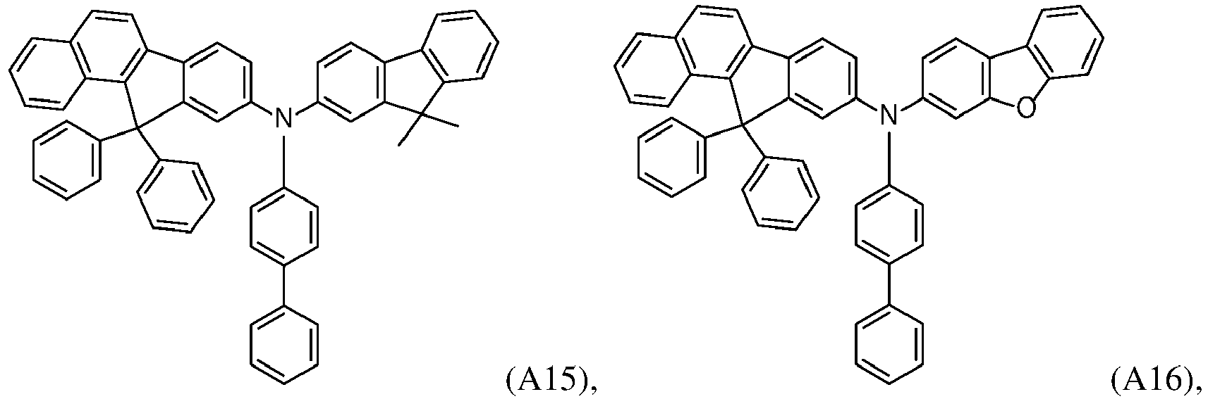


- An organic semiconductor layer comprising a benzo diphenyl fluorene compound of formula I according to any of the preceding claims 1 to 8.
- The organic semiconductor layer according to claim 8, wherein the semiconductor layer is a hole injection layer and/or hole transport layer.
- The organic semiconductor layer according to claim 9 or 10, wherein the organic semiconductor layer comprises in addition an organic p-dopant.
- The organic semiconductor layer according to claim 11, wherein the organic p-dopant is a radialene compound.
- The organic semiconductor layer according to claim 11 or 12, wherein the organic p-dopant is a radialene compound of formula (II)
 A1 are independently selected from a group (1)
 Ar1 is independently selected from substituted or unsubstituted C6 to C36 aryl and
substituted or unsubstituted C2 to C36 heteroaryl;if Ar1 is substituted, the one or more substituents are independently selected from an electron-withdrawing group, F, CN, partially perfluorinated or perfluorinated alkyl, -NO2;A2 and A3 are independently selected from a group (2) Ar2 and Ar3 are independently selected from substituted or unsubstituted C6 to C36 aryl
and substituted or unsubstituted C2 to C36 heteroaryl; andif Ar2 and Ar3 are substituted, the one or more substituents are independently selected from an electron-withdrawing group, F, CN, partially perfluorinated or perfluorinated alkyl, -NO2; each R' is independently selected from an electron-withdrawing group. - An organic electronic device comprising at least one semiconductor layer according to claims 9 to 13.
- The organic electronic device according to claim 14, comprising an anode layer, a cathode layer and at least one organic semiconductor layer, wherein at least one organic semiconductor layer is arranged between the anode layer and the cathode layer.
- The organic electronic device according to claim 14 or 15, wherein the organic electronic device is an organic light emitting diode (OLED), a light emitting device, thin film transistor, a battery, a display device or an organic photovoltaic cell (OPV).
Priority Applications (4)
| Application Number | Priority Date | Filing Date | Title |
|---|---|---|---|
| CN202280038457.4A CN117730639A (en) | 2021-06-18 | 2022-06-15 | Organic electronic device comprising a compound of formula (I), display device comprising said organic electronic device, and compound of formula (I) |
| PCT/EP2022/066327 WO2022263519A1 (en) | 2021-06-18 | 2022-06-15 | Organic electronic device comprising a compound of formula (i), display device comprising the organic electronic device as well as compounds of formula (i) |
| KR1020237041588A KR20240023386A (en) | 2021-06-18 | 2022-06-15 | Organic electronic devices comprising compounds of formula (I), display devices comprising organic electronic devices, as well as compounds of formula (I) |
| EP22737391.7A EP4356445A1 (en) | 2021-06-18 | 2022-06-15 | Organic electronic device comprising a compound of formula (i), display device comprising the organic electronic device as well as compounds of formula (i) |
Applications Claiming Priority (1)
| Application Number | Priority Date | Filing Date | Title |
|---|---|---|---|
| EP21180322.6A EP4106026A1 (en) | 2021-06-18 | 2021-06-18 | An organic electronic device comprising a substrate, an anode layer, a cathode layer, at least one first emission layer, and at least one hole injection layer that comprises a metal complex |
Publications (1)
| Publication Number | Publication Date |
|---|---|
| EP4106028A1 true EP4106028A1 (en) | 2022-12-21 |
Family
ID=76532055
Family Applications (3)
| Application Number | Title | Priority Date | Filing Date |
|---|---|---|---|
| EP21180322.6A Pending EP4106026A1 (en) | 2021-06-18 | 2021-06-18 | An organic electronic device comprising a substrate, an anode layer, a cathode layer, at least one first emission layer, and at least one hole injection layer that comprises a metal complex |
| EP21215975.0A Pending EP4106028A1 (en) | 2021-06-18 | 2021-12-20 | Organic electronic device comprising a compound of formula (i), display device comprising the organic electronic device as well as compounds of formula (i) |
| EP22737382.6A Pending EP4356444A1 (en) | 2021-06-18 | 2022-06-15 | An organic electronic device comprising a substrate, an anode layer, a cathode layer, at least one first emission layer, and at least one hole injection layer that comprises a metal complex |
Family Applications Before (1)
| Application Number | Title | Priority Date | Filing Date |
|---|---|---|---|
| EP21180322.6A Pending EP4106026A1 (en) | 2021-06-18 | 2021-06-18 | An organic electronic device comprising a substrate, an anode layer, a cathode layer, at least one first emission layer, and at least one hole injection layer that comprises a metal complex |
Family Applications After (1)
| Application Number | Title | Priority Date | Filing Date |
|---|---|---|---|
| EP22737382.6A Pending EP4356444A1 (en) | 2021-06-18 | 2022-06-15 | An organic electronic device comprising a substrate, an anode layer, a cathode layer, at least one first emission layer, and at least one hole injection layer that comprises a metal complex |
Country Status (5)
| Country | Link |
|---|---|
| EP (3) | EP4106026A1 (en) |
| KR (1) | KR20240023511A (en) |
| CN (1) | CN117441422A (en) |
| TW (1) | TW202315185A (en) |
| WO (1) | WO2022263494A1 (en) |
Citations (3)
| Publication number | Priority date | Publication date | Assignee | Title |
|---|---|---|---|---|
| EP2722908A1 (en) | 2012-10-17 | 2014-04-23 | Novaled AG | Phosphorescent OLED and hole transporting materials for phosphorescent OLEDs |
| CN107602441A (en) * | 2017-10-16 | 2018-01-19 | 长春海谱润斯科技有限公司 | A kind of fused ring compound and its organic luminescent device |
| US20200365813A1 (en) * | 2018-02-15 | 2020-11-19 | Hodogaya Chemical Co., Ltd. | Organic electroluminescence element |
Family Cites Families (3)
| Publication number | Priority date | Publication date | Assignee | Title |
|---|---|---|---|---|
| EP3133664A1 (en) * | 2015-08-18 | 2017-02-22 | Novaled GmbH | Triaryl amine thick layer doped with metal amides for use as hole injection layer for an organic light-emitting diode (oled) |
| EP4084108A1 (en) | 2015-08-18 | 2022-11-02 | Novaled GmbH | Metal amides for use as hil for an organic light-emitting diode (oled) |
| DE102015121844A1 (en) | 2015-12-15 | 2017-06-22 | Osram Oled Gmbh | Organic electronic device and use of a fluorinated sulfonimide metal salt |
-
2021
- 2021-06-18 EP EP21180322.6A patent/EP4106026A1/en active Pending
- 2021-12-20 EP EP21215975.0A patent/EP4106028A1/en active Pending
-
2022
- 2022-06-15 EP EP22737382.6A patent/EP4356444A1/en active Pending
- 2022-06-15 TW TW111122185A patent/TW202315185A/en unknown
- 2022-06-15 CN CN202280039073.4A patent/CN117441422A/en active Pending
- 2022-06-15 KR KR1020237042077A patent/KR20240023511A/en unknown
- 2022-06-15 WO PCT/EP2022/066280 patent/WO2022263494A1/en active Application Filing
Patent Citations (3)
| Publication number | Priority date | Publication date | Assignee | Title |
|---|---|---|---|---|
| EP2722908A1 (en) | 2012-10-17 | 2014-04-23 | Novaled AG | Phosphorescent OLED and hole transporting materials for phosphorescent OLEDs |
| CN107602441A (en) * | 2017-10-16 | 2018-01-19 | 长春海谱润斯科技有限公司 | A kind of fused ring compound and its organic luminescent device |
| US20200365813A1 (en) * | 2018-02-15 | 2020-11-19 | Hodogaya Chemical Co., Ltd. | Organic electroluminescence element |
Non-Patent Citations (5)
| Title |
|---|
| CAS , no. 1427316-55-9 |
| CAS, no. 1427556-50-0 |
| CAS, no. 2225845-23-6 |
| CRC HANDBOOK OF CHEMISTRY AND PHYSICS, 2008, pages 12 - 114 |
| YASUHIKO SHIROTAHIROSHI KAGEYAMA, CHEM. REV., vol. 107, 2007, pages 953 - 1010 |
Also Published As
| Publication number | Publication date |
|---|---|
| TW202315185A (en) | 2023-04-01 |
| WO2022263494A1 (en) | 2022-12-22 |
| CN117441422A (en) | 2024-01-23 |
| KR20240023511A (en) | 2024-02-22 |
| EP4106026A1 (en) | 2022-12-21 |
| EP4356444A1 (en) | 2024-04-24 |
Similar Documents
| Publication | Publication Date | Title |
|---|---|---|
| EP3989305A1 (en) | Organic electronic device comprising a compound of formula (1), display device comprising the organic electronic device as well as compounds of formula (1) for use in organic electronic devices | |
| EP3232490A1 (en) | Organic light emitting diode comprising an organic semiconductor layer | |
| KR20210108976A (en) | Compound and organic semiconducting layer, organic electronic device and display device comprising same | |
| CN114555580A (en) | Compound, and organic semiconductor layer, organic electronic device, display device, and lighting device each comprising same | |
| EP3828951A1 (en) | Organic electronic device and display device comprising the organic electronic device as well as organic compounds for use in organic electronic devices | |
| EP3567039B1 (en) | N-heteroarylene compounds with low lumo energies | |
| EP4036080A1 (en) | Organic compound of formula (i) for use in organic electronic devices, an organic electronic device comprising a compound of formula (i) and a display device comprising the organic electronic device | |
| US20230056322A1 (en) | Organic Electronic Device Comprising a Compound of Formula (I), Display Device Comprising the Organic Electronic Device as Well as Compounds of Formula (I) for Use in Organic Electronic Devices | |
| EP4106028A1 (en) | Organic electronic device comprising a compound of formula (i), display device comprising the organic electronic device as well as compounds of formula (i) | |
| EP3693352A1 (en) | Compound and an organic semiconducting layer, an organic electronic device and a display or lighting device comprising the same | |
| EP3930024B1 (en) | Organic electronic device and display device comprising the organic electronic device as well as a composition for use in organic electronic devices | |
| EP4169092B1 (en) | Organic electronic device and display device comprising the organic electronic device as well as a composition for use in organic electronic devices | |
| EP3989302A1 (en) | Organic compound of formula (i) for use in organic electronic devices, an organic electronic device comprising a compound of formula (i) and a display device comprising the organic electronic device | |
| EP3930023A1 (en) | Organic electronic device comprising a compound of formula (1), display device comprising the organic electronic device as well as compounds of formula (1) for use in organic electronic devices | |
| EP4333590A1 (en) | Organic electroluminescent device comprising a compound of formula (i) and a compound of formula (ii), and display device comprising the organic electroluminescent device | |
| EP4106025A1 (en) | Organic electronic device comprising a compound of formula (1), display device comprising the organic electronic device as well as compounds of formula (1) for use in organic electronic devices | |
| EP4099412A1 (en) | An organic electroluminescent device and a compound for use therein | |
| EP3989304A1 (en) | Organic compound of formula (i) for use in organic electronic devices, an organic electronic device comprising a compound of formula (i) and a display device comprising the organic electronic device | |
| EP4155303A1 (en) | Organic compound of formula (i) for use in organic electronic devices, a composition comprising a compound of formula (iv) and at least one compound of formula (iva) to (ivd), an organic semiconductor layer comprising the compound or composition, an organic electronic device comprising the organic semiconductor layer, and a display device comprising the organic electronic device | |
| EP3920249A1 (en) | Compound, intermediate of the compound, process for preparing the compound, organic semiconducting material comprising the compound, organic electronic device comprising the same, and display device and lighting device comprising the same | |
| EP4287282A1 (en) | Organic electroluminescent device comprising a compound of formula (i) and a compound of formula (ii), and display device comprising the organic electroluminescent device | |
| EP4333591A1 (en) | Organic electroluminescent device comprising a compound of formula (i) and a compound of formula (ii), and display device comprising the organic electroluminescent device | |
| EP4156314A1 (en) | Organic electronic device and a compound | |
| EP4344390A1 (en) | Organic electroluminescent device comprising a radialene of formula (i) and a compound of formula (ii), and display device comprising the organic electroluminescent device | |
| EP3930022A1 (en) | Organic electronic device and display device comprising the organic electronic device as well as a composition for use in organic electronic devices |
Legal Events
| Date | Code | Title | Description |
|---|---|---|---|
| PUAI | Public reference made under article 153(3) epc to a published international application that has entered the european phase |
Free format text: ORIGINAL CODE: 0009012 |
|
| STAA | Information on the status of an ep patent application or granted ep patent |
Free format text: STATUS: THE APPLICATION HAS BEEN PUBLISHED |
|
| AK | Designated contracting states |
Kind code of ref document: A1 Designated state(s): AL AT BE BG CH CY CZ DE DK EE ES FI FR GB GR HR HU IE IS IT LI LT LU LV MC MK MT NL NO PL PT RO RS SE SI SK SM TR |
|
| STAA | Information on the status of an ep patent application or granted ep patent |
Free format text: STATUS: REQUEST FOR EXAMINATION WAS MADE |
|
| 17P | Request for examination filed |
Effective date: 20230619 |
|
| RBV | Designated contracting states (corrected) |
Designated state(s): AL AT BE BG CH CY CZ DE DK EE ES FI FR GB GR HR HU IE IS IT LI LT LU LV MC MK MT NL NO PL PT RO RS SE SI SK SM TR |