EP4105889A1 - Procédé et appareil de traitement de réalité augmentée, support de stockage et dispositif électronique - Google Patents
Procédé et appareil de traitement de réalité augmentée, support de stockage et dispositif électronique Download PDFInfo
- Publication number
- EP4105889A1 EP4105889A1 EP21772070.5A EP21772070A EP4105889A1 EP 4105889 A1 EP4105889 A1 EP 4105889A1 EP 21772070 A EP21772070 A EP 21772070A EP 4105889 A1 EP4105889 A1 EP 4105889A1
- Authority
- EP
- European Patent Office
- Prior art keywords
- target object
- point information
- anchor point
- image
- module
- Prior art date
- Legal status (The legal status is an assumption and is not a legal conclusion. Google has not performed a legal analysis and makes no representation as to the accuracy of the status listed.)
- Withdrawn
Links
- 238000003672 processing method Methods 0.000 title claims abstract description 31
- 230000003190 augmentative effect Effects 0.000 title claims abstract description 9
- 238000012545 processing Methods 0.000 claims abstract description 41
- 238000010801 machine learning Methods 0.000 claims description 22
- 230000004044 response Effects 0.000 claims description 17
- 238000013507 mapping Methods 0.000 claims description 9
- 230000000007 visual effect Effects 0.000 claims description 9
- 238000004590 computer program Methods 0.000 claims description 5
- 238000000605 extraction Methods 0.000 claims description 5
- 238000000034 method Methods 0.000 description 31
- 230000006870 function Effects 0.000 description 19
- 230000008569 process Effects 0.000 description 19
- 238000010586 diagram Methods 0.000 description 14
- 238000004891 communication Methods 0.000 description 9
- 230000005236 sound signal Effects 0.000 description 7
- 238000012549 training Methods 0.000 description 7
- 241001122767 Theaceae Species 0.000 description 6
- 230000001133 acceleration Effects 0.000 description 5
- 238000005516 engineering process Methods 0.000 description 5
- 241000282326 Felis catus Species 0.000 description 4
- 238000004422 calculation algorithm Methods 0.000 description 4
- 230000008859 change Effects 0.000 description 4
- 239000011521 glass Substances 0.000 description 4
- 230000003993 interaction Effects 0.000 description 4
- 230000002452 interceptive effect Effects 0.000 description 4
- 230000033001 locomotion Effects 0.000 description 4
- 238000005259 measurement Methods 0.000 description 3
- 238000010295 mobile communication Methods 0.000 description 3
- 230000005540 biological transmission Effects 0.000 description 2
- 210000000988 bone and bone Anatomy 0.000 description 2
- 238000004364 calculation method Methods 0.000 description 2
- 238000013527 convolutional neural network Methods 0.000 description 2
- 230000000694 effects Effects 0.000 description 2
- 230000005484 gravity Effects 0.000 description 2
- 230000010365 information processing Effects 0.000 description 2
- 238000012986 modification Methods 0.000 description 2
- 230000004048 modification Effects 0.000 description 2
- 230000003287 optical effect Effects 0.000 description 2
- 238000009877 rendering Methods 0.000 description 2
- 230000009471 action Effects 0.000 description 1
- 230000003044 adaptive effect Effects 0.000 description 1
- 238000004458 analytical method Methods 0.000 description 1
- 238000013528 artificial neural network Methods 0.000 description 1
- 230000006399 behavior Effects 0.000 description 1
- 230000006835 compression Effects 0.000 description 1
- 238000007906 compression Methods 0.000 description 1
- 230000004069 differentiation Effects 0.000 description 1
- 230000005611 electricity Effects 0.000 description 1
- 238000011156 evaluation Methods 0.000 description 1
- 238000010191 image analysis Methods 0.000 description 1
- 230000001788 irregular Effects 0.000 description 1
- 239000010985 leather Substances 0.000 description 1
- 230000004807 localization Effects 0.000 description 1
- 230000005389 magnetism Effects 0.000 description 1
- 239000013307 optical fiber Substances 0.000 description 1
- 230000002093 peripheral effect Effects 0.000 description 1
- 238000011176 pooling Methods 0.000 description 1
- 238000012797 qualification Methods 0.000 description 1
- 239000004065 semiconductor Substances 0.000 description 1
- 230000003238 somatosensory effect Effects 0.000 description 1
- 230000003068 static effect Effects 0.000 description 1
- 239000013598 vector Substances 0.000 description 1
Images


Classifications
-
- G—PHYSICS
- G06—COMPUTING; CALCULATING OR COUNTING
- G06T—IMAGE DATA PROCESSING OR GENERATION, IN GENERAL
- G06T7/00—Image analysis
- G06T7/70—Determining position or orientation of objects or cameras
- G06T7/73—Determining position or orientation of objects or cameras using feature-based methods
-
- G—PHYSICS
- G06—COMPUTING; CALCULATING OR COUNTING
- G06V—IMAGE OR VIDEO RECOGNITION OR UNDERSTANDING
- G06V20/00—Scenes; Scene-specific elements
- G06V20/20—Scenes; Scene-specific elements in augmented reality scenes
-
- G—PHYSICS
- G06—COMPUTING; CALCULATING OR COUNTING
- G06F—ELECTRIC DIGITAL DATA PROCESSING
- G06F3/00—Input arrangements for transferring data to be processed into a form capable of being handled by the computer; Output arrangements for transferring data from processing unit to output unit, e.g. interface arrangements
- G06F3/01—Input arrangements or combined input and output arrangements for interaction between user and computer
- G06F3/011—Arrangements for interaction with the human body, e.g. for user immersion in virtual reality
- G06F3/012—Head tracking input arrangements
-
- G—PHYSICS
- G06—COMPUTING; CALCULATING OR COUNTING
- G06F—ELECTRIC DIGITAL DATA PROCESSING
- G06F3/00—Input arrangements for transferring data to be processed into a form capable of being handled by the computer; Output arrangements for transferring data from processing unit to output unit, e.g. interface arrangements
- G06F3/01—Input arrangements or combined input and output arrangements for interaction between user and computer
- G06F3/016—Input arrangements with force or tactile feedback as computer generated output to the user
-
- G—PHYSICS
- G06—COMPUTING; CALCULATING OR COUNTING
- G06F—ELECTRIC DIGITAL DATA PROCESSING
- G06F3/00—Input arrangements for transferring data to be processed into a form capable of being handled by the computer; Output arrangements for transferring data from processing unit to output unit, e.g. interface arrangements
- G06F3/01—Input arrangements or combined input and output arrangements for interaction between user and computer
- G06F3/048—Interaction techniques based on graphical user interfaces [GUI]
- G06F3/0481—Interaction techniques based on graphical user interfaces [GUI] based on specific properties of the displayed interaction object or a metaphor-based environment, e.g. interaction with desktop elements like windows or icons, or assisted by a cursor's changing behaviour or appearance
- G06F3/04815—Interaction with a metaphor-based environment or interaction object displayed as three-dimensional, e.g. changing the user viewpoint with respect to the environment or object
-
- G—PHYSICS
- G06—COMPUTING; CALCULATING OR COUNTING
- G06T—IMAGE DATA PROCESSING OR GENERATION, IN GENERAL
- G06T19/00—Manipulating 3D models or images for computer graphics
- G06T19/006—Mixed reality
-
- G—PHYSICS
- G06—COMPUTING; CALCULATING OR COUNTING
- G06V—IMAGE OR VIDEO RECOGNITION OR UNDERSTANDING
- G06V10/00—Arrangements for image or video recognition or understanding
- G06V10/20—Image preprocessing
- G06V10/25—Determination of region of interest [ROI] or a volume of interest [VOI]
-
- G—PHYSICS
- G06—COMPUTING; CALCULATING OR COUNTING
- G06V—IMAGE OR VIDEO RECOGNITION OR UNDERSTANDING
- G06V10/00—Arrangements for image or video recognition or understanding
- G06V10/40—Extraction of image or video features
- G06V10/44—Local feature extraction by analysis of parts of the pattern, e.g. by detecting edges, contours, loops, corners, strokes or intersections; Connectivity analysis, e.g. of connected components
- G06V10/443—Local feature extraction by analysis of parts of the pattern, e.g. by detecting edges, contours, loops, corners, strokes or intersections; Connectivity analysis, e.g. of connected components by matching or filtering
- G06V10/449—Biologically inspired filters, e.g. difference of Gaussians [DoG] or Gabor filters
- G06V10/451—Biologically inspired filters, e.g. difference of Gaussians [DoG] or Gabor filters with interaction between the filter responses, e.g. cortical complex cells
- G06V10/454—Integrating the filters into a hierarchical structure, e.g. convolutional neural networks [CNN]
-
- G—PHYSICS
- G06—COMPUTING; CALCULATING OR COUNTING
- G06V—IMAGE OR VIDEO RECOGNITION OR UNDERSTANDING
- G06V10/00—Arrangements for image or video recognition or understanding
- G06V10/70—Arrangements for image or video recognition or understanding using pattern recognition or machine learning
- G06V10/74—Image or video pattern matching; Proximity measures in feature spaces
-
- G—PHYSICS
- G06—COMPUTING; CALCULATING OR COUNTING
- G06V—IMAGE OR VIDEO RECOGNITION OR UNDERSTANDING
- G06V10/00—Arrangements for image or video recognition or understanding
- G06V10/70—Arrangements for image or video recognition or understanding using pattern recognition or machine learning
- G06V10/77—Processing image or video features in feature spaces; using data integration or data reduction, e.g. principal component analysis [PCA] or independent component analysis [ICA] or self-organising maps [SOM]; Blind source separation
- G06V10/7715—Feature extraction, e.g. by transforming the feature space, e.g. multi-dimensional scaling [MDS]; Mappings, e.g. subspace methods
-
- G—PHYSICS
- G06—COMPUTING; CALCULATING OR COUNTING
- G06V—IMAGE OR VIDEO RECOGNITION OR UNDERSTANDING
- G06V10/00—Arrangements for image or video recognition or understanding
- G06V10/70—Arrangements for image or video recognition or understanding using pattern recognition or machine learning
- G06V10/82—Arrangements for image or video recognition or understanding using pattern recognition or machine learning using neural networks
-
- G—PHYSICS
- G06—COMPUTING; CALCULATING OR COUNTING
- G06T—IMAGE DATA PROCESSING OR GENERATION, IN GENERAL
- G06T2207/00—Indexing scheme for image analysis or image enhancement
- G06T2207/20—Special algorithmic details
- G06T2207/20081—Training; Learning
-
- G—PHYSICS
- G06—COMPUTING; CALCULATING OR COUNTING
- G06V—IMAGE OR VIDEO RECOGNITION OR UNDERSTANDING
- G06V2201/00—Indexing scheme relating to image or video recognition or understanding
- G06V2201/07—Target detection
Definitions
- the present disclosure relates to the field of augmented reality (AR) technologies, and in particularly to, an AR processing method, an AR processing apparatus, a computer readable storage medium, and an electronic device.
- AR augmented reality
- AR is a technology that integrates virtual information with the real world. In recent years, the AR technology has been extended to many application fields.
- a surrounding scene is usually scanned through a smart phone, and then a virtual object is placed in the scene to observe the virtual object in different positions and perspectives; or motions or behaviors of the virtual object are controlled through different interactive ways, so as to realize AR experiences.
- the present disclosure provides an AR processing method, an AR processing apparatus, a computer readable storage medium, and an electronic device, thereby overcoming, at least to a certain extent, problems of poor operational accuracy and low operational efficiency.
- an AR processing method is provided and implemented by a cloud server, including: receiving an image uploaded by a first device, and recognizing the image to determine a target object of the image; recognizing a region of interest (ROI) of the target object in response to finding, based on a type of the target object, a type in associated object types is the same as the type of the target object; and analyzing anchor point information corresponding to the target object to enable a second device to render the anchor point information and the region of interest and display the target object.
- ROI region of interest
- an AR processing apparatus is provided and applied to a cloud server, the apparatus includes: a target object recognition module, configured to receive an image uploaded by a first device, and recognize the image to determine a target object of the image; a region determining module, configured to recognize a region of interest of the target object in response to finding, based on a type of the target object, a type in associated object types is the same as the type of the target object; and an anchor analyzing module, configured to analyze anchor point information corresponding to the target object to enable a second device to render the anchor point information and the region of interest and display the target object.
- a target object recognition module configured to receive an image uploaded by a first device, and recognize the image to determine a target object of the image
- a region determining module configured to recognize a region of interest of the target object in response to finding, based on a type of the target object, a type in associated object types is the same as the type of the target object
- an anchor analyzing module configured to analyze anchor point information corresponding to the target object to enable
- a computer readable storage medium is provided and stored with computer programs therein, the computer programs are configured to, when executed by a processor, to implement the above AR processing method.
- an electronic device includes: a processor; and a memory configured to store one or more programs therein, and the processor is configured to execute the one or more programs stored in the memory to implement the above AR processing method.
- FIG. 1 illustrates a schematic diagram of an exemplary system architecture to which an AR processing method or an AR processing apparatus may be applied according to the embodiment of the present disclosure.
- a system architecture 100 may include a first device 110, a cloud server 120, and a second device 130.
- the number of the second device may be one or more, and types and locations of the plurality of second devices may be the same or different.
- a multi-user AR scene can be built by the first device, the cloud server and the second device.
- the first device 110 may be a device that performs relocation and is a participating end of AR scenes.
- the first device 110 can be integrated with a module to realize simultaneous localization and mapping (SLAM), and can install and run applications for the AR scenes.
- SLAM simultaneous localization and mapping
- the present disclosure does not limit a type of the first device 110, which can be a mobile phone, a tablet computer, and a smart wearable device such as AR glasses, an AR helmet, a smart watch, etc.
- the first device 110 can be a combination of the AR helmet and a game console to realize a somatosensory AR scene.
- the cloud server 120 can store information generated from a mapping device during mapping processes, therefore the first device can be relocated.
- the cloud server 120 can perform an interactive data processing process of the AR game, that is, the cloud server 120 can process data generated from the first device 110 and feedback.
- the cloud server 120 can be used to provide device configuration requirements of the AR scene, so as to allocate virtual objects to the first device 110 and control the virtual objects in response to spatial state changes of the first device 110.
- the first device 110 can acquire an image and send the image to the cloud server 120.
- the cloud server 120 determines a target object of the image
- the cloud server 120 can determine a region of interest (ROI) corresponding to a type of the target object, and obtain, by analyzing, anchor point information corresponding to the target object, so as to enable the second device 130 to render and display the anchor point information and the ROI.
- ROI region of interest
- the anchor point information is stored in the cloud server and sent to the second device, therefore the user can see the target object on the second device with a help of the anchor point information.
- device terminals participating in the AR scene of the present disclosure may include other devices in addition to the first device and the second device, and types of the other devices may be the same or different from the first device and the second device here.
- the present disclosure does not limit the number and the types of the other devices.
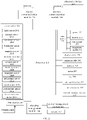
- FIG. 2 illustrates a schematic structural diagram of an electronic device according to an embodiment of the present disclosure, that is, the first device may be configured as, for example, the device illustrated in FIG. 2 . It should be noted that the electronic device illustrated in FIG. 2 is only an example and should not bring any restrictions on functions and the scope of use of the embodiments of the present disclosure.
- the electronic device of the present disclosure includes at least a processor and a memory for storing one or more programs.
- the processor can implement the AR processing method of the exemplary embodiment of the present disclosure.
- an electronic device 200 may include: a processor 210, an internal memory 221, an external memory interface 222, an universal serial bus (USB) interface 230, a charging management module 240, a power management module 241, a battery 242, an antenna 1, an antenna 2, a mobile communication module 250, a wireless communication module 260, an audio module 270, a speaker 271, a receiver 272, a microphone 273, a headphone socket 274, a sensor module 280, a display screen 290, a camera module 291, an indicator 292, a motor 293, a key 294, a subscriber identification module (SIM) card interface 295, etc.
- SIM subscriber identification module
- the sensor module 280 may include a depth sensor 2801, a pressure sensor 2802, a gyroscope sensor 2803, a barometric sensor 2804, a magnetic sensor 2805, an acceleration sensor 2806, a distance sensor 2807, a proximity sensor 2808, a fingerprint sensor 2809, a temperature sensor 2810, a touch sensor 2811, an ambient light sensor 2812, a bone conduction sensor 2813, etc.
- the structure illustrated in the embodiment of the present disclosure does not constitute a specific limitation on the electronic device 200.
- the electronic device 200 may include more or fewer components than the illustrated structure, or combine some components, or split some components, or perform different component arrangements.
- the illustrated components may be implemented in hardware, software, or a combination of software and hardware.
- the processor 210 may include one or more processing units.
- the processor 210 may include an application processor (AP), a modulation and demodulation processor, a graphics processing unit (GPU), an image signal processor (ISP), a controller, a video codec, a digital signal processor (DSP), a baseband processor and/or a neural-network processing unit (NPU), etc.
- AP application processor
- ISP image signal processor
- DSP digital signal processor
- NPU neural-network processing unit
- different processing units can be independent devices or integrated in one or more processors.
- a memory may be provided in the processor 210 for storing instructions and data.
- the USB interface 230 is an interface that conforms to USB standard specification, which can be a mini-USB interface, a micro-USB interface, or a USB Type-C interface, etc.
- the USB interface 230 can be used to connect a charger to charge the electronic device 200, and can further be used to transmit data between the electronic device 200 and peripheral devices. It can further be used to connect headphones and play audio through the headphones.
- the USB interface 230 can further be used to connect other electronic devices, such as AR devices.
- the charging management module 240 is used to receive charging input from the charger.
- the charger can be a wireless charger or a wired charger.
- the power management module 241 is used to connect the battery 242, the charging management module 240 and the processor 210.
- the power management module 241 can be used to receive input from the battery 242 and/or the charging management module 240 and supply power to the processor 210, the internal memory 221, the display screen 290, the camera module 291, the wireless communication module 260, and the like.
- a wireless communication function of the electronic device 200 can be realized by the antenna 1, the antenna 2, the mobile communication module 250, the wireless communication module 260, the modulation and demodulation processor, the baseband processor, etc.
- the mobile communication module 250 can be used to provide wireless communication solutions including 2-generation wireless telephone technology (2G)/3G/4G/5G applied to the electronic device 200.
- the wireless communication module 260 can be used to provide wireless communication solutions applied to the electronic device 200 including wireless local area networks (WLAN) (such as wireless fidelity (Wi-Fi) networks), BLUETOOTH (BT), global navigation satellite system (GNSS), frequency modulation (FM), near field communication (NFC), and infrared technology (IR).
- WLAN wireless local area networks
- BT wireless fidelity
- GNSS global navigation satellite system
- FM frequency modulation
- NFC near field communication
- IR infrared technology
- the electronic device 200 can realize a display function through the GPU, the display screen 290, the application processor, etc.
- the GPU is a microprocessor for image processing, which connects the display screen 290 and the application processor.
- the GPU can be used to perform mathematical and geometric calculations, and render graphics.
- the processor 210 may include one or more GPUs that execute program instructions to generate or change display information.
- the electronic device 200 can realize a camera function through the ISP, the camera module 291, the video codec, the GPU, the display screen 290, the application processor, etc.
- the electronic device 200 may include one or N numbers of the camera modules 291, and N is a positive integer greater than 1. If the electronic device 200 includes the N numbers of cameras, one of the N numbers of cameras is a main camera.
- the internal memory 221 can be used to store computer executable program codes, which include instructions.
- the internal memory 221 may include a storage program area and a storage data area.
- the external memory interface 222 can be used to connect an external memory card, such as a micro security digital (SD) card, to expand a storage capacity of the electronic device 200.
- SD micro security digital
- the electronic device 200 can realize an audio function through the audio module 270, the speaker 271, the receiver 272, the microphone 273, the headphone socket 274, the application processor, and the like.
- the audio function such as music playing, recording, etc.
- the audio module 270 can be used to convert digital audio information into analog audio signal outputs, and be also used to convert analog audio inputs into digital audio signals.
- the audio module 270 may further be used to encode and decode audio signals.
- the audio module 270 may be provided in the processor 210, or some functional modules of the audio module 270 may be provided in the processor 210.
- the speaker 271 also known as “horn” can be used to convert audio electrical signals into sound signals.
- the electronic device 200 can listen to music through the speaker 271 or listen to hands-free calls.
- voices can be answered by placing the receiver 272 close to the human ear.
- the user can make a sound through the mouth close to the microphone 273 and input the sound signal to the microphone 273.
- the electronic device 200 may be provided with at least one the microphone 273.
- the headphone socket 274 can be used to connect wired headphones.
- the depth sensor 2801 can be used to obtain depth information of a scene.
- the pressure sensor 2802 can be used to sense a pressure signal and can convert the pressure signal into an electrical signal.
- the gyroscope sensor 2803 can be used to determine a motion pose of the electronic device 200.
- the barometric sensor 2804 can be used to measure air pressure.
- the magnetic sensor 2805 may include a Hall sensor.
- the electronic device 200 can use the magnetic sensor 2805 to detect opening and closing of a flip leather case.
- the acceleration sensor 2806 can be used to detect an acceleration of the electronic device 200 in all directions (generally three axes).
- the distance sensor 2807 can be used to measure distance.
- the proximity sensor 2808 may include, for example, a light emitting diode (LED) and a light detector, such as a photodiode.
- the fingerprint sensor 2809 can be used to collect fingerprints.
- the temperature sensor 2810 can be used to detect temperature.
- the touch sensor 2811 can be used to transmit a detected touch operation to the application processor to determine a type of this touch event. Visual output related to the touch operation can be provided through the display screen 290.
- the ambient light sensor 2812 can be used to sense a brightness of an ambient light.
- the bone conduction sensor 2813 can be used to acquire vibration signals.
- the key 294 may include a power on key, a volume key, etc.
- the key 294 may be a mechanical key or a touch key.
- the motor 293 can generate vibration prompts.
- the motor 293 can be used for vibrate alert or touch vibration feedback.
- the indicator 292 may be an indicator light, which can be used to indicate a charge state, a charge change, messages, missed calls, notifications, etc.
- the SIM card interface 295 may be used to connect a SIM card.
- the electronic device 200 interacts with the network through the SIM card to realize the functions of call and data communication.
- the present disclosure further provides a computer readable storage medium, which can be included in the electronic device described in the above embodiment, or it can exist alone without being assembled into the electronic device.
- the computer readable storage medium may be, for example, but is not limited to, one of a system, an apparatus and a device with electricity, magnetism, optics, electromagnetism, infrared ray, or semiconductor, or any combination of the above. More specific examples of the computer readable storage media may include, but be not limited to, electrical connections with one or more wires, portable computer disks, hard disks, random access memory (RAM), read only memory (ROM), erasable programmable read only memory (EPROM or flash memory), optical fibers, portable compact disk read only memory (CD-ROM), optical storage devices, magnetic storage devices or any suitable combination of the above.
- the computer readable storage medium may be any tangible medium containing or storing programs, which may be used by or in combination with an instruction execution system, apparatus, or device.
- the computer readable storage medium may send, propagate, or transmit programs for use by or in combination with the instruction execution system, apparatus, or device.
- Program codes of the computer readable storage medium can be transmitted by any suitable manner, including but not limited to: wireless, wire, optical cable, radio frequency (RF), etc., or any suitable combination of the above.
- the computer readable storage medium is stored with one or more programs therein, and when the one or more programs are executed by the electronic device, the electronic device realizes a method described in the following embodiment.
- each block in the flowchart or block diagram can represent a module, a program segment, or a part of the code; and the module, the program segment, or the part of the code contains one or more executable instructions for realizing specified logical functions.
- the function marked in the block may also occur in a different order than those marked in the drawings. For example, two consecutive blocks can actually be executed in basically parallel, or the two consecutive blocks can be executed in the opposite order, which depends on the function involved.
- each block in the block diagram or flowchart and the combination of blocks in the block diagram or flowchart can be realized by a dedicated hardware-based system that performs specified functions or operations, or by a combination of dedicated hardware and computer instructions.
- the units described in the embodiments of the present disclosure can be implemented by software or hardware, and the described units can also be set in the processor.
- the names of these units do not constitute a qualification of the unit itself under certain circumstances.
- a cloud server recognizes the image outputted from a first device to obtain a target object of an image, determines a ROI of the target object when a type in associated object types is the same as a type of the target object, sends the ROI and the type of the target object to a second device to enable the second device to render, based on anchor point information obtained by analysis, the ROI to display the target object.
- the embodiment of the present disclosure provides a cloud server architecture for supporting the terminal device, and the cloud server is used to recognize images and match types to recognize the ROI.
- the cloud server Because the cloud server has rich computing resources, it will not be affected by the performance of the terminal device itself, and complex algorithms are migrated to the cloud server, which can improve the calculation efficiency and accuracy, therefore the accuracy and efficiency of operation in the AR scene can be improved.
- the cloud server because the cloud server handles the complex computing processes, it reduces the resource consumption of the terminal device, does not increase loads of the terminal device, improves reliability, reduces limitations, and increases the scope of application.
- the target object of the image is recognized through the cloud server, and an appropriate way is selected to determine the ROI according to the object matching results, and then the anchor point information is analyzed, the second device can display the target object according to the anchor point information, which improves the efficiency and convenience of displaying the target object.
- FIG. 3 illustrates a schematic flowchart of an AR processing method according to an embodiment of the present disclosure.
- the AR processing method may begin from block S310 to block S330, which are described in detail as follows.
- the first device may be any one of a plurality of AR devices that perform a multi-user AR interaction process.
- the first device may be a terminal device with image acquisition function or an AR device. Specifically, the image can be acquired through a configured front camera or a plurality of rear cameras.
- the first device can support an existing AR engine to facilitate AR interaction based on the existing AR engine.
- a type of the first device may include but be not limited to a mobile phone, a tablet, AR glasses, an AR helmet, etc.
- the first device may further include AR applications, a camera, a SLAM module and an inertial measurement unit (IMU).
- AR applications a scene image of a current environment can be captured by the first device as the image in a built map, and depth information corresponding to the captured image can be obtained by using its equipped depth sensor.
- the preset application can be an application with AR function selected by the user from installed applications on the terminal device, such as the AR application.
- the captured image may be a still image or an image in a moving state, etc.
- the image may include one or more objects.
- an environment around the cat such as cups, bear dolls, etc.
- the cat, cups, bear dolls, etc. are the objects included in the image.
- the first device After the first device acquires the image, it can output the captured image to the cloud server based on the AR engine contained therein.
- the cloud server may include an object recognizing and tracking module and an anchor management module.
- the object recognizing and tracking module may be used to recognize the image and track a recognized target object.
- the anchor management module may be used to perform management operation on anchor point information, such as adjustment, modification or addition. It should be noted that the cloud server in the embodiment of the present disclosure and the modules of the cloud server have platform independence and can support all platforms with AR capabilities.
- the first device can continuously send the captured image to the cloud server to improve the transmission efficiency and ensure the continuity of recognition.
- the cloud server can recognize the image to determine the target object contained in the image.
- the target object can be image content or elements contained in the image, and the target object can be an object such as cat, dog, table, or people.
- the target object of the image can be one or more, which is not limited here.
- the cloud server When the cloud server recognizes the image, it can use a pre-trained machine learning model to perform the recognizing by the object recognizing and tracking model, so as to improve the recognizing efficiency and accuracy.
- the pre-trained machine learning model can be, for example, a convolutional neural networks (CNN).
- CNN convolutional neural networks
- the present disclosure does not limit a model structure and parameter configuration of the machine learning model.
- the present disclosure further provides a training method of a machine learning model.
- the training method can be implemented by the cloud server, or the pre-trained machine learning model can be uploaded to the cloud server by other terminal devices after the training is completed.
- FIG. 4 illustrates a schematic flowchart of recognizing a target object of an image. Please refer to FIG. 4 , the recognizing a target object of an image can be performed by block S410 and block S420.
- a convolution layer, a pooling layer and a fully connected layer of the pre-trained machine learning model can be used to extract feature data used to characterize features or characteristics of the image as the image features.
- a size and number of convolution kernels in the convolution layer can be set according to actual needs.
- the feature data may include, but are not limited to, shape features, texture features, and the like.
- a machine learning model can be trained to obtain the pre-trained machine learning model.
- a process of training the machine learning model may include: training the machine learning model based on sample images and types of the sample images to obtain the pre-trained machine learning model.
- each of the sample images refers to an image with a known type.
- the sample image can contain the same or different object of the image to be processed, and a scene of the sample image can be the same or different from that of the image to be processed.
- the number of the sample images can be multiple to improve the accuracy and reliability of the training.
- sample images can be used as inputs of the machine learning model to obtain prediction types of the sample images, and the model can be trained based on manually determined types of the sample images until the prediction types are consistent with the manually determined types or until the model converges to end the training model processes and obtain the pre-trained machine learning model, so as to improve the accuracy and reliability of the model.
- the image features can be predicted by the pre-trained machine learning model to obtain the types of the objects of the image.
- the prediction processing here can be realized by a convolution of the image features through the convolution layer and a fully connected processing of the image features through the fully connected layer. Recognizing the objects in the image by the pre-trained machine learning model, the accuracy and efficiency of the object recognizing can be improved. In addition, other suitable methods can also be used to recognize the objects in the image, which are not specifically limited here.
- text, vectors or other types of marks can be used to uniquely represent each type, so as to quickly distinguish each type through the unique marks.
- the pre-trained machine learning model can be deployed to the cloud server to improve processing efficiency and reduce the resource consumption of the terminal device.
- the image of the current frame captured by the terminal device is an image 1.
- the image 1 is inputted to the pre-trained machine learning model to convolute the image 1 through the pre-trained machine learning model to obtain that the target object of the image 1 is a cup.
- the existing associated object types can be searched based on the type of the target object.
- the associated object types refer to multiple object types with associated anchor point information stored in the cloud server in advance for searching and matching by other terminal devices.
- the anchor management module and the object recognizing and tracking module in the cloud server the association between the object type and the anchor point information can be established.
- the associated object type it can be associated with the corresponding anchor point information.
- the corresponding anchor point information may include a location A, a picture B, a text C, and so on.
- the type of the target object can be matched with each of types of the associated object types to obtain a matching result indicating whether the type of the target object is consistent with the associated object type. If the matching result is that the type of the target object is matched with the type of the associated object types successful, it is determined that there is the same type as the target object in the associated object types stored in the cloud server. If the matching result is that the type of the target object fails to match all the types of the associated object types, it is determined that there is no type with the same type as the target object in the associated object types stored in the cloud server.
- the anchor point information of the target object can be processed based on the matching result, therefore a virtual model corresponding to the target object can be displayed on the second device to realize the interactive operation in the AR scene.
- the anchor point information can be quickly determined according to the matching result, and the efficiency of the determination can be improved.
- the matching result is that searching the same type as the target object in the associated object types. If it is determined that the type in the associated object types is the same as the type of the target object, the searched result can be fed back to the object recognizing and tracking module in the cloud server, and the object recognizing and tracking module can be started to recognize the ROI of the target object through the object recognizing and tracking module.
- the ROI is an image region selected from the image, which is a focus of image analysis.
- the ROI is selected for further processing.
- the ROI can be outlined by boxes, circles, ellipses, irregular polygons, etc. Using the ROI to determine the target to be processed in the image can reduce the processing time, improve the efficiency and increase the accuracy.
- the first device may be in the moving state with the user's movement, therefore the target object is in the moving state.
- the ROI of the target object can be determined by object tracking. Specifically, tracking the target object and determining a position where the target object is placed; and determining a region where the position is located as the ROI of the target object, and tracking the ROI in real time to place the target object in the ROI.
- the position where the target object is located can be determined according to a placement object where the target object is located.
- the placement object is a real object used to support the target object.
- the placement object can be static or in motion, and can be any object indoors or outdoors, such as tea table, table, sofa and other objects. Therefore, the position of the replacement object corresponding to the target object is used to represent the position of the target object. Furthermore, a region of the replacement object where the target object is located can be determined and regarded as the ROI. Therefore, the ROI in the embodiment of the present disclosure refers to the region for placing the target object.
- an object where a target object cup is placed is a tea table
- the tea table can be recognized and the region where the tea table is located can be extracted, thus the region where the tea table is located can be tracked in real time to obtain the ROI of the target object cup, so as to place the target object in the region where the tea table is located.
- a virtual model of a target object in an image generated by a computer can be placed on an object in the real scene.
- a tracking algorithm can be used to track the position and/or direction of the object placed in the real scene (i.e., placement object), and generated tracking data can be used to make the target object move with the placement object, so as to continue to maintain the target object on the placement object and produce a real AR effect.
- tracking the placement object When tracking the placement object, it can continuously and stably track changes of the position and pose of the first device relative to the surrounding environment, and output three-dimensional coordinate information of characteristics of the surrounding environment. Specifically, various appropriate tracking algorithms can be used to achieve, thus the user can move and browse from any angle. Even after leaving and returning, the placed target object will still stay in the original position.
- the type of the target object and the specific information of the ROI can be returned to the SLAM module for further processing.
- analyzing the anchor point information corresponding to the target object to enable the second device to render the anchor point information and the ROI and display the target object.
- the anchor point information can correspond to the target object. Specifically, it can be determined from the anchor point information corresponding to the matched associated object type according to the searched result, that is, the anchor point information corresponding to the matched associated object type is used as the anchor point information of the target object.
- the anchor point information may specifically include a position of the target object and a content used to describe the target object.
- the content used to describe the target object can be used to represent what kind of object the target object is, that is, the type of the target object, which can specifically include but not limited to any one or more combinations of text, image, video and audio.
- the position of the target object refers to coordinates of the virtual model of the target object in a reference coordinate system of the first device.
- the anchor point information can be generated by the first device and hosted to the cloud server for storage, therefore the second device can view and interact with the target object.
- the first device can send visual mapping data to the cloud server, and the visual mapping data can be processed into sparse point cloud data by the cloud server, so as to facilitate hosting the sparse point cloud data sent from the first device.
- the visual mapping data may include key point information, map point information and so on.
- the second device is in the same scene as the first device, which can be another device in the plurality of AR devices that perform the multi-user AR interaction process, and its type can be the same as the first device.
- both the first device and the second device are mobile phones, or both are AR glasses.
- the types of the first device and the second device can be different, for example, the first device is a mobile phone, and the second device is AR glasses.
- the present disclosure does not limit the types of the first device and the second device.
- the second device may include an AR application, a camera, a SLAM module and an inertial measurement unit.
- the first device and the second device are powered on separately, and the equipped camera modules are respectively used to scan the real scene and establish their own maps.
- the camera module can be a monocular camera module, or a binocular or multi camera module.
- An upper AR application of the second device can render the region of interest and the target object in an APP layer of the application after obtaining the region of interest framed with the target object and the type information of the target object through the SLAM module.
- the anchor point information can be analyzed in response to an analyze request of the terminal device.
- the terminal device that sends the analyze request can be the terminal device that needs to view the target object, for example, it can be the second device.
- Analyzing the anchor point information can make multiple terminal devices in a given physical space use the previously managed anchor point information to establish a common reference framework.
- the second device will send the visual feature descriptor from the current framework to the cloud server to send the analyze request to the cloud server.
- the cloud server After receiving the analyze request, the cloud server will try to match the visual characteristics with the sparse point cloud data in the anchor point information. If the matching is successful, the analyzing of the anchor point information can be performed. In this way, the analyzed anchor point information can be placed in the same position and orientation in the environment for each terminal device to achieve the function of the multi-user AR.
- the cloud server can send the anchor point information to each second device in the same AR scene that needs to view the target object. Because the first device and the second device are different, their positions and poses may be different, so the cloud server can send the analyzed anchor point information to the second device based on a position relationship between the first device and the second device.
- the anchor point information can be converted from the reference coordinate system of the first device to a reference coordinate system of the second device to obtain converted anchor point information, and the converted anchor point information can be sent to the second device.
- the reference coordinate system of the first device can be a coordinate system established by the first device according to the current position of the first device when starting the AR application.
- obtaining a gravity acceleration direction of the first device taking a current position of the first device as an origin of the reference coordinate system, and taking the gravity acceleration direction as a Z axis of the reference coordinate system.
- the specific orientations of a X axis and a Y axis perpendicular to the Z axis can be unlimited.
- the reference coordinate system of the second device can refer to a coordinate system established by the second device according to a current position of the second device when starting the AR application.
- the implementation method can refer to the reference coordinate system of the first device, which will not be repeated here.
- FIG. 5 illustrates a schematic specific flowchart of converting the anchor point information.
- the converting the anchor point information can specifically include block S510 and block S520.
- the relative pose relationship may refer to a mapping relationship between the reference coordinate systems of two terminal devices.
- the relative pose relationship between the second device and the first device can be obtained according to a pose of the current frame in the second device relative to the reference coordinate system of the first device and pose information of the current frame.
- point cloud information in a dense map built by the first device can be associated with the image features of the current frame through visual feature matching based on a feature descriptor, so as to obtain the pose of the current frame relative to the reference coordinate system of the first device.
- the cloud server can convert the anchor point information from the reference coordinate system of the first device to the reference coordinate system of the second device according to the relative pose relationship. Specifically, it can convert position information of the anchor point information, so as to realize the transmission of the anchor point information of the target object uploaded by the first device to the second device.
- the second device After the second device obtains the analyzed anchor point information, it can render and display the anchor point information and the ROI of the target object at the same time, so as to display the target object and the region of interest at the corresponding position on the second device, so as to realize the effect of multiple users viewing the target object from different positions in the multi-user AR scene.
- each terminal device can view the anchor point information about the target object uploaded by the first device hosted in the cloud server, which improves the accuracy and pertinence of the second device to view the anchor point information, and accurately realizes the multi-user AR scene.
- the second device can adjust the converted anchor point information of the target object in the same way as the first device by scanning the surrounding scene.
- An adjustment operation can include but not limited to editing, modifying, and adding.
- the target object is a shopping mall
- evaluation information and other information associated with the target object can be added to update the anchor point information.
- the second device can upload the updated anchor point information to the anchor management module in the cloud server for hosting, so as to update the anchor point information about the target object stored in the anchor management module.
- the latest anchor point information can be grasped in time, and thus the user can view the most accurate virtual object corresponding to the target object, and the interactive experience and realism can be improved.
- the type of the target object when searching from the associated object types according to the type of the target object, if the type that is the same as the type of the target object is not searched, it is determined that there is no type that is the same as the type of the target object.
- the type of the target object can be transmitted to the second device, the second device can build the anchor point information corresponding to the target object according to the type of the target object, and host the anchor point information on the cloud server to display the target object according to the anchor point information.
- the type of the target object can be fed back to the SLAM module of the second device for subsequent processing through the SLAM module of the second device.
- the type of the target object can be passed to the upper AR application (APP) through the SLAM module of the second device.
- the AR APP can create the anchor point information about the target object according to a new target object recognized by the object recognizing and tracking module in the cloud server, that is, to add an anchor.
- the newly created anchor point information can include the position of the target object, the specific content of the target object, and so on.
- the newly created anchor point information and the type of the recognized target object can be uploaded to the anchor management module for association, therefore the cloud server can host the anchor point information.
- the process of hosting the anchor point information can include: the second device will send relevant visual mapping data of the anchor point information associated with the target object from the user's environment to the cloud server. After uploading, the anchor point information will be processed into sparse point cloud data by the cloud server, therefore the second device can obtain the sparse point cloud data, determine the relationship between the two devices, and display the target object on the second device according to the sparse point cloud data.
- the sparse point cloud data can be used to represent a testable description of the three-dimensional real world.
- FIG. 6 illustrates a schematic diagram of specific processes of an AR processing method. Referring to FIG. 6 , the AR processing method may begin from block S601 to block S606.
- an inertial measurement unit and a camera of a first device transmit data to a SLAM module.
- the SLAM module transmits captured images to an object recognizing and tracking module in a cloud server to recognize target objects of constantly uploaded images through the object recognizing and tracking module.
- an anchor management module in the cloud server searches the existing associated object types according to an object type currently transmitted, if the same object type is found in the associated object types, associates the object with the anchor point information, and feedbacks the result to the object recognizing and tracking module.
- the object recognizing and tracking module starts object tracking after receiving the corresponding associated object information, tracks the region of interest of the target object recognized in the uploaded image in real time, and transmits the object type and the region of interest information back to the SLAM module.
- the SLAM module sends the region of interest to an application, which renders it, hosts the anchor point information on the cloud server, and sends information to the anchor management module in the cloud server according to the object type information to request to analyze the anchor point information associated with the target object.
- the anchor management module returns the analyzed anchor point information associated with the target object to the application.
- the cloud server architecture is used to provide support for the terminal device, and the cloud server is used to perform image recognition, type matching, region of interest recognition and other processes. Because the cloud server has rich computing resources, it will not be affected by the performance of the terminal device itself. Migrating complex algorithms to the cloud server can improve computing efficiency and accuracy, so as to improve the accuracy and efficiency of operation in the AR scenes. On another hand, the resource consumption of the terminal device can be reduced, the reliability and stability of the multi-user AR scene can be improved, and the scope of application can be increased.
- the cloud server can be used to realize the matching and determination of the anchor point information, which improves the efficiency through the matching, and by determining the region of interest, the accuracy of rendering can be improved, which will not cause too much burden on the terminal device, and it is simple to implement and has strong applicability.
- the anchor point information of the first device is converted through the relative pose relationship between the first device and the second device, and the user can adjust the anchor point information, which can improve the user's sense of participation and enhance the authenticity of reality interaction. Furthermore, by searching the type of the target object in the associated object types, different ways are used to process the anchor point information of different searched results, so as to improve the comprehensiveness and accuracy of the processing.
- an exemplary embodiment of the present disclosure further provides an AR processing apparatus, applied to an AR game in which at least a first device participates.
- FIG. 7 illustrates a schematic block diagram of an AR processing apparatus according to an exemplary embodiment of the present disclosure.
- the AR processing apparatus 700 of the exemplary embodiment of the present disclosure may include the following modules.
- a target object recognition module 701 is configured to receive an image uploaded by a first device, and recognize the image to determine a target object of the image.
- a region determining module 702 is configured to recognize a region of interest of the target object in response to searching, based on a type of the target object, a type in associated object types is the same as the type of the target object.
- An anchor analyzing module 703 is configured to analyze anchor point information corresponding to the target object to enable a second device to render the anchor point information and the region of interest and display the target object.
- the target object recognition module may include: a feature extracting module, configured to perform feature extraction on the image by a pre-trained machine learning model to obtain image features of the image; and a prediction module, configured to perform prediction processing on the image features to determine the target object of the image.
- the region determining module may include: a position determining module, configured to track the target object and determine a position where the target object is placed; and a region tracking module, configured to determine a region where the position is located as the region of interest of the target object, and track the region of interest in real time to place the target object in the region of interest.
- the anchor analyzing module may include: an anchor sending module, configured to analyze the anchor point information corresponding to the target object and send the anchor point information to the second device, in response to an analyze request sent from the second device.
- the anchor sending module may include: an anchor converting module, configured to convert the anchor point information from a reference coordinate system of the first device to a reference coordinate system of the second device to obtain converted anchor point information, and send the converted anchor point information to the second device.
- the anchor converting module may include: a pose determining module, configured to acquire a relative pose relationship between the second device and the first device based on pose information of the first device and pose information of the second device; and a converting control module, configured to convert the anchor point information to the reference coordinate system of the second device based on the relative pose relationship to obtain the converted anchor point information.
- the apparatus further includes: an anchor updating module, configured to update the anchor point information of the target object in response to an adjustment operation of the second device for the anchor point information.
- the apparatus further includes: an anchor new module, configured to transmit, in response to determining that there is no type in the associated object types is the same as the type of the target object, the type of the target object to the second device to enable the second device to build anchor point information corresponding to the target object based on the type of the target object, and host the anchor point information to display the target object.
- an anchor new module configured to transmit, in response to determining that there is no type in the associated object types is the same as the type of the target object, the type of the target object to the second device to enable the second device to build anchor point information corresponding to the target object based on the type of the target object, and host the anchor point information to display the target object.
- the exemplary embodiments described here can be implemented by software or by combining software with necessary hardware. Therefore, the technical solutions according to the embodiments of the present disclosure can be embodied in the form of a software product, which can be stored in a non-transitory storage medium (which can be compact disc read-only memory (CD-ROM), USB flash disk, mobile hard disk, etc.) or on a network, including several instructions to enable a computing device (which can be a personal computer, a server, a terminal device, or a network device, etc.) to execute the method according to the embodiments of the present disclosure.
- a computing device which can be a personal computer, a server, a terminal device, or a network device, etc.
Landscapes
- Engineering & Computer Science (AREA)
- Theoretical Computer Science (AREA)
- Physics & Mathematics (AREA)
- General Physics & Mathematics (AREA)
- General Engineering & Computer Science (AREA)
- Computer Vision & Pattern Recognition (AREA)
- Multimedia (AREA)
- Software Systems (AREA)
- Evolutionary Computation (AREA)
- Artificial Intelligence (AREA)
- General Health & Medical Sciences (AREA)
- Health & Medical Sciences (AREA)
- Medical Informatics (AREA)
- Computing Systems (AREA)
- Databases & Information Systems (AREA)
- Human Computer Interaction (AREA)
- Computer Graphics (AREA)
- Computer Hardware Design (AREA)
- Life Sciences & Earth Sciences (AREA)
- Biodiversity & Conservation Biology (AREA)
- Biomedical Technology (AREA)
- Molecular Biology (AREA)
- Processing Or Creating Images (AREA)
- User Interface Of Digital Computer (AREA)
Applications Claiming Priority (2)
| Application Number | Priority Date | Filing Date | Title |
|---|---|---|---|
| CN202010192967.XA CN111445583B (zh) | 2020-03-18 | 2020-03-18 | 增强现实处理方法及装置、存储介质和电子设备 |
| PCT/CN2021/072704 WO2021184952A1 (fr) | 2020-03-18 | 2021-01-19 | Procédé et appareil de traitement de réalité augmentée, support de stockage et dispositif électronique |
Publications (2)
| Publication Number | Publication Date |
|---|---|
| EP4105889A1 true EP4105889A1 (fr) | 2022-12-21 |
| EP4105889A4 EP4105889A4 (fr) | 2023-08-02 |
Family
ID=71629287
Family Applications (1)
| Application Number | Title | Priority Date | Filing Date |
|---|---|---|---|
| EP21772070.5A Withdrawn EP4105889A4 (fr) | 2020-03-18 | 2021-01-19 | Procédé et appareil de traitement de réalité augmentée, support de stockage et dispositif électronique |
Country Status (4)
| Country | Link |
|---|---|
| US (1) | US20220392104A1 (fr) |
| EP (1) | EP4105889A4 (fr) |
| CN (1) | CN111445583B (fr) |
| WO (1) | WO2021184952A1 (fr) |
Families Citing this family (9)
| Publication number | Priority date | Publication date | Assignee | Title |
|---|---|---|---|---|
| CN111445583B (zh) * | 2020-03-18 | 2023-08-01 | Oppo广东移动通信有限公司 | 增强现实处理方法及装置、存储介质和电子设备 |
| CN114200895A (zh) * | 2020-09-17 | 2022-03-18 | 北京小米移动软件有限公司 | 设备控制方法、装置及存储介质 |
| CN112330747B (zh) * | 2020-09-25 | 2022-11-11 | 中国人民解放军军事科学院国防科技创新研究院 | 基于无人机平台的多传感器联合探测和显示方法 |
| CN112270736B (zh) * | 2020-11-16 | 2024-03-01 | Oppo广东移动通信有限公司 | 增强现实处理方法及装置、存储介质和电子设备 |
| CN112699331A (zh) * | 2020-12-31 | 2021-04-23 | 深圳市慧鲤科技有限公司 | 留言信息展示方法及装置、电子设备和存储介质 |
| US12008806B2 (en) * | 2021-08-19 | 2024-06-11 | Meta Platforms Technologies, Llc | Methods and systems to allow three-dimensional map sharing between heterogeneous computing systems, cross-localization, and sharing content in three-dimensional space |
| CN113724398A (zh) * | 2021-09-01 | 2021-11-30 | 北京百度网讯科技有限公司 | 增强现实方法、装置、设备以及存储介质 |
| CN116974497A (zh) * | 2022-04-22 | 2023-10-31 | 华为技术有限公司 | 增强现实显示方法、装置、设备及存储介质 |
| CN116977600B (zh) * | 2023-07-03 | 2024-04-09 | 玩出梦想(上海)科技有限公司 | 一种xr设备及xr设备高度采集方法 |
Family Cites Families (12)
| Publication number | Priority date | Publication date | Assignee | Title |
|---|---|---|---|---|
| US20130222371A1 (en) * | 2011-08-26 | 2013-08-29 | Reincloud Corporation | Enhancing a sensory perception in a field of view of a real-time source within a display screen through augmented reality |
| JP5937128B2 (ja) * | 2014-03-17 | 2016-06-22 | 富士フイルム株式会社 | 拡張現実感提供システム、方法及びプログラム |
| CN107222468B (zh) * | 2017-05-22 | 2020-12-18 | 北京邮电大学 | 增强现实处理方法、终端、云端服务器和边缘服务器 |
| US10019654B1 (en) * | 2017-06-28 | 2018-07-10 | Accenture Global Solutions Limited | Image object recognition |
| CN108550190A (zh) * | 2018-04-19 | 2018-09-18 | 腾讯科技(深圳)有限公司 | 增强现实数据处理方法、装置、计算机设备和存储介质 |
| US10937249B2 (en) * | 2018-05-07 | 2021-03-02 | Google Llc | Systems and methods for anchoring virtual objects to physical locations |
| CN108664231B (zh) * | 2018-05-11 | 2021-02-09 | 腾讯科技(深圳)有限公司 | 2.5维虚拟环境的显示方法、装置、设备及存储介质 |
| CN108961375A (zh) * | 2018-06-20 | 2018-12-07 | 腾讯科技(深圳)有限公司 | 一种根据二维图像生成三维图像的方法及装置 |
| CN109141647A (zh) * | 2018-08-01 | 2019-01-04 | 北京百度网讯科技有限公司 | 机房温度监测方法和装置 |
| CN110866133B (zh) * | 2018-08-27 | 2024-04-02 | 阿里巴巴集团控股有限公司 | 信息搜索方法、页面显示方法、系统及设备 |
| CN109656363B (zh) * | 2018-09-04 | 2022-04-15 | 亮风台(上海)信息科技有限公司 | 一种用于设置增强交互内容的方法与设备 |
| CN111445583B (zh) * | 2020-03-18 | 2023-08-01 | Oppo广东移动通信有限公司 | 增强现实处理方法及装置、存储介质和电子设备 |
-
2020
- 2020-03-18 CN CN202010192967.XA patent/CN111445583B/zh active Active
-
2021
- 2021-01-19 WO PCT/CN2021/072704 patent/WO2021184952A1/fr unknown
- 2021-01-19 EP EP21772070.5A patent/EP4105889A4/fr not_active Withdrawn
-
2022
- 2022-08-16 US US17/820,084 patent/US20220392104A1/en active Pending
Also Published As
| Publication number | Publication date |
|---|---|
| CN111445583A (zh) | 2020-07-24 |
| EP4105889A4 (fr) | 2023-08-02 |
| WO2021184952A1 (fr) | 2021-09-23 |
| US20220392104A1 (en) | 2022-12-08 |
| CN111445583B (zh) | 2023-08-01 |
Similar Documents
| Publication | Publication Date | Title |
|---|---|---|
| EP4105889A1 (fr) | Procédé et appareil de traitement de réalité augmentée, support de stockage et dispositif électronique | |
| CN111325842B (zh) | 地图构建方法、重定位方法及装置、存储介质和电子设备 | |
| CN111476911B (zh) | 虚拟影像实现方法、装置、存储介质与终端设备 | |
| US12020385B2 (en) | Augmented reality processing method, storage medium, and electronic device | |
| CN112270754B (zh) | 局部网格地图构建方法及装置、可读介质和电子设备 | |
| US20220262035A1 (en) | Method, apparatus, and system for determining pose | |
| US9392248B2 (en) | Dynamic POV composite 3D video system | |
| CN111815666B (zh) | 图像处理方法及装置、计算机可读存储介质和电子设备 | |
| EP4243390A1 (fr) | Procédé et appareil d'affichage d'objet virtuel, et support de stockage et dispositif électronique | |
| US11989400B2 (en) | Data sharing method and device | |
| CN111311758A (zh) | 增强现实处理方法及装置、存储介质和电子设备 | |
| CN110572716B (zh) | 多媒体数据播放方法、装置及存储介质 | |
| WO2022252823A1 (fr) | Procédé et appareil de génération d'une vidéo en direct | |
| WO2022206494A1 (fr) | Procédé et dispositif de suivi de cible | |
| CN112115282A (zh) | 基于搜索的问答方法、装置、设备及存储介质 | |
| CN111739517A (zh) | 语音识别方法、装置、计算机设备及介质 | |
| CN112581571A (zh) | 虚拟形象模型的控制方法、装置、电子设备及存储介质 | |
| CN112581358A (zh) | 图像处理模型的训练方法、图像处理方法及装置 | |
| CN111985252B (zh) | 对话翻译方法及装置、存储介质和电子设备 | |
| CN111982293B (zh) | 体温测量方法、装置、电子设备及存储介质 | |
| CN111462335B (zh) | 基于虚拟对象交互的设备控制方法及装置、介质和设备 | |
| CN111310701B (zh) | 手势识别方法、装置、设备及存储介质 | |
| CN115605835A (zh) | 显示设备与终端设备的交互方法、存储介质及电子设备 | |
| CN111757005A (zh) | 拍摄控制方法及装置、计算机可读介质和电子设备 | |
| CN111367492A (zh) | 网页页面展示方法及装置、存储介质 |
Legal Events
| Date | Code | Title | Description |
|---|---|---|---|
| STAA | Information on the status of an ep patent application or granted ep patent |
Free format text: STATUS: THE INTERNATIONAL PUBLICATION HAS BEEN MADE |
|
| PUAI | Public reference made under article 153(3) epc to a published international application that has entered the european phase |
Free format text: ORIGINAL CODE: 0009012 |
|
| STAA | Information on the status of an ep patent application or granted ep patent |
Free format text: STATUS: REQUEST FOR EXAMINATION WAS MADE |
|
| 17P | Request for examination filed |
Effective date: 20220913 |
|
| AK | Designated contracting states |
Kind code of ref document: A1 Designated state(s): AL AT BE BG CH CY CZ DE DK EE ES FI FR GB GR HR HU IE IS IT LI LT LU LV MC MK MT NL NO PL PT RO RS SE SI SK SM TR |
|
| REG | Reference to a national code |
Ref country code: DE Ref legal event code: R079 Free format text: PREVIOUS MAIN CLASS: G06T0019000000 Ipc: G06V0020200000 |
|
| DAV | Request for validation of the european patent (deleted) | ||
| DAX | Request for extension of the european patent (deleted) | ||
| A4 | Supplementary search report drawn up and despatched |
Effective date: 20230629 |
|
| RIC1 | Information provided on ipc code assigned before grant |
Ipc: G06T 19/00 20110101ALI20230623BHEP Ipc: G06V 20/20 20220101AFI20230623BHEP |
|
| STAA | Information on the status of an ep patent application or granted ep patent |
Free format text: STATUS: THE APPLICATION HAS BEEN WITHDRAWN |
|
| 18W | Application withdrawn |
Effective date: 20231204 |