EP4105743A1 - Control system, relay device, and access management program - Google Patents
Control system, relay device, and access management program Download PDFInfo
- Publication number
- EP4105743A1 EP4105743A1 EP20919128.7A EP20919128A EP4105743A1 EP 4105743 A1 EP4105743 A1 EP 4105743A1 EP 20919128 A EP20919128 A EP 20919128A EP 4105743 A1 EP4105743 A1 EP 4105743A1
- Authority
- EP
- European Patent Office
- Prior art keywords
- access
- control
- unit
- authentication
- external device
- Prior art date
- Legal status (The legal status is an assumption and is not a legal conclusion. Google has not performed a legal analysis and makes no representation as to the accuracy of the status listed.)
- Pending
Links
Images





Classifications
-
- G—PHYSICS
- G05—CONTROLLING; REGULATING
- G05B—CONTROL OR REGULATING SYSTEMS IN GENERAL; FUNCTIONAL ELEMENTS OF SUCH SYSTEMS; MONITORING OR TESTING ARRANGEMENTS FOR SUCH SYSTEMS OR ELEMENTS
- G05B19/00—Program-control systems
- G05B19/02—Program-control systems electric
- G05B19/04—Program control other than numerical control, i.e. in sequence controllers or logic controllers
- G05B19/05—Programmable logic controllers, e.g. simulating logic interconnections of signals according to ladder diagrams or function charts
- G05B19/058—Safety, monitoring
-
- G—PHYSICS
- G05—CONTROLLING; REGULATING
- G05B—CONTROL OR REGULATING SYSTEMS IN GENERAL; FUNCTIONAL ELEMENTS OF SUCH SYSTEMS; MONITORING OR TESTING ARRANGEMENTS FOR SUCH SYSTEMS OR ELEMENTS
- G05B19/00—Program-control systems
- G05B19/02—Program-control systems electric
- G05B19/04—Program control other than numerical control, i.e. in sequence controllers or logic controllers
- G05B19/05—Programmable logic controllers, e.g. simulating logic interconnections of signals according to ladder diagrams or function charts
-
- G—PHYSICS
- G05—CONTROLLING; REGULATING
- G05B—CONTROL OR REGULATING SYSTEMS IN GENERAL; FUNCTIONAL ELEMENTS OF SUCH SYSTEMS; MONITORING OR TESTING ARRANGEMENTS FOR SUCH SYSTEMS OR ELEMENTS
- G05B19/00—Program-control systems
- G05B19/02—Program-control systems electric
- G05B19/04—Program control other than numerical control, i.e. in sequence controllers or logic controllers
- G05B19/042—Program control other than numerical control, i.e. in sequence controllers or logic controllers using digital processors
-
- G—PHYSICS
- G06—COMPUTING OR CALCULATING; COUNTING
- G06F—ELECTRIC DIGITAL DATA PROCESSING
- G06F21/00—Security arrangements for protecting computers, components thereof, programs or data against unauthorised activity
- G06F21/60—Protecting data
- G06F21/606—Protecting data by securing the transmission between two devices or processes
-
- G—PHYSICS
- G06—COMPUTING OR CALCULATING; COUNTING
- G06F—ELECTRIC DIGITAL DATA PROCESSING
- G06F21/00—Security arrangements for protecting computers, components thereof, programs or data against unauthorised activity
- G06F21/60—Protecting data
- G06F21/62—Protecting access to data via a platform, e.g. using keys or access control rules
-
- G—PHYSICS
- G05—CONTROLLING; REGULATING
- G05B—CONTROL OR REGULATING SYSTEMS IN GENERAL; FUNCTIONAL ELEMENTS OF SUCH SYSTEMS; MONITORING OR TESTING ARRANGEMENTS FOR SUCH SYSTEMS OR ELEMENTS
- G05B2219/00—Program-control systems
- G05B2219/10—Plc systems
- G05B2219/11—Plc I-O input output
- G05B2219/1108—Relay module
-
- G—PHYSICS
- G05—CONTROLLING; REGULATING
- G05B—CONTROL OR REGULATING SYSTEMS IN GENERAL; FUNCTIONAL ELEMENTS OF SUCH SYSTEMS; MONITORING OR TESTING ARRANGEMENTS FOR SUCH SYSTEMS OR ELEMENTS
- G05B2219/00—Program-control systems
- G05B2219/10—Plc systems
- G05B2219/14—Plc safety
- G05B2219/14006—Safety, monitoring in general
Definitions
- the present invention relates to a control system, a relay device, and an access management program, and more specifically, to a control system that controls a control object, a relay device that relays access from an external device to a control device that controls the control object, and an access management program for managing access from the external device to the control device that controls the control object.
- Machines and equipment used in a production site using factory automation are typically controlled by a control device such as a programmable controller (programmable logic controller; hereinafter, also referred to as a "PLC").
- a control device such as a programmable controller (programmable logic controller; hereinafter, also referred to as a "PLC”).
- PLC programmable logic controller
- Such a control device is configured to be able to communicate with an external device.
- Japanese Patent Laying-Open No. 2001-175615 discloses a production system including a device agent associated with a machine tool and an agent management server that manages the device agent.
- the control system includes a control unit configured to control the control object and communicate with an external device, and a relay unit configured to relay access from the external device to the control unit.
- the relay unit includes a reception unit configured to receive an authentication request from a request source, an authentication unit configured to authenticate validity of the request source upon receipt of the authentication request by the reception unit, and an access management unit configured to control a restriction level of access from the external device to the control unit when the validity of the request source is authenticated by the authentication unit.
- the restriction level of access from the external device to the control unit is controlled by the relay unit that relays access from the external device to the control unit when the validity of the request source is authenticated by the relay unit, it is possible to improve security without changing the external device that runs on a legacy application.
- the authentication unit authenticates the validity of the request source based on predetermined authentication data.
- the authentication unit authenticates the validity of the request source with communications from the request source concealed.
- control unit communicates with the external device in accordance with a type of a management mode
- access management unit controls the restriction level of access from the external device in accordance with the type of the management mode
- the relay unit controls the restriction level of access from the external device to the control unit in accordance with the type of the management mode, is it possible to improve security while taking the operation aspect into consideration.
- the relay unit keeps a log of access from the external device to the control unit.
- the access management unit controls, based on a list for controlling the restriction level of access from the external device to the control unit, the restriction level of access from the external device to the control unit when the validity of the request source is authenticated by the authentication unit.
- the list is updated when an incident occurs in access from the external device to the control unit.
- a relay device configured to relay access from an external device to a control device configured to control a control object.
- the relay device includes a reception unit configured to receive an authentication request from a request source, an authentication unit configured to authenticate validity of the request source upon receipt of the authentication request by the reception unit, and an access management unit configured to control a restriction level of access from the external device to the control device when the validity of the request source is authenticated by the authentication unit.
- the restriction level of access from the external device to the control device is controlled by the relay device that relays access from the external device to the control device when the validity of the request source is authenticated by the relay device, it is possible to improve security without changing the external device that runs on a legacy application.
- an access management program configured to manage access from an external device to a control device configured to control a control object.
- the access management program causes a computer to execute a reception step of receiving an authentication request from a request source, an authentication step of authenticating validity of the request source upon receipt of the authentication request in the reception step, and an access management step of controlling a restriction level of access from the external device to the control device when the validity of the request source is authenticated in the authentication step.
- the restriction level of access from the external device to the control device is controlled by the access management program for managing access from the external device to the control device when the validity of the request source is authenticated by the access management program, it is possible to improve security without changing the external device that runs on a legacy application.
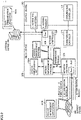
- Fig. 1 is a schematic diagram for describing a control system 1a according to the present embodiment.
- control system 1a includes a control unit 100a, an external device 700a, and a relay unit 200a.
- Control unit 100a is configured to control a control object and communicate with external device 700a via relay unit 200a.
- Control unit 100a corresponds to the function of an industrial controller that controls control objects such as various types of equipment or apparatus, and typically corresponds to a function included in a programmable logic controller (PLC).
- PLC programmable logic controller
- Control unit 100a controls the control object (not illustrated) in accordance with a user program designed in advance.
- Examples of the control object include various industrial equipment for automating a production process used in the field of FA.
- the examples of the control object include a robot controller, an arm robot controlled by a robot controller, a servomotor controlled by a servo driver, a visual sensor configured to take an image of a workpiece, and other equipment used in a production process.
- External device 700a is configured to be able to communicate with control unit 100a via relay unit 200a. External device 700a collects, from control unit 100a, and accumulates various data. The various data accumulated by external device 700a contains data on the control of the control object performed by control unit 100a. For example, the various data accumulated by external device 700a contains information on traceability measured from the workpiece.
- Relay unit 200a relays access from external device 700a to control unit 100a.
- relay unit 200a includes a communication controller 210a and a network controller 220a including a port 2201a.
- Communication controller 210a is responsible for exchanging data with a communication controller 110a included in control unit 100a. Data acquired from control unit 100a via communication controller 210a is transmitted to external device 700a via port 2201a of network controller 220a.
- control unit 100a and relay unit 200a may be included in different devices, or may be included in the same device.
- a PLC which is an example of the device including control unit 100a, may have the function of control unit 100a but not the function of relay unit 200a, or may have the function of control unit 100a and the function of relay unit 200a.
- control system 1a having such a configuration, external device 700a accesses control unit 100a via relay unit 200a to collect, from control unit 100a, and accumulates various data.
- external device 700a runs on a so-called legacy application in many cases.
- a relatively new security technology such as VPN is implemented in order to ensure communications between external device 700a and control unit 100a used in the related art are maintained in a secure state
- the system may need to be significantly changed in its entirety, which requires a significant increase in cost or a temporary halt on the operation of the production site.
- relay unit 200a includes a reception unit 230a, an authentication unit 240a, and an access management unit 250a.
- Reception unit 230a receives an authentication request from a request source 500a.
- Authentication unit 240a authenticates the validity of request source 500a upon receipt of the authentication request by reception unit 230a.
- Access management unit 250a controls a restriction level of access from external device 700a to control unit 100a when authentication unit 240a authenticates the validity of request source 500a.
- Request source 500a is a function unit that starts (kicks off) a series of processes of requesting access from external device 700a to control unit 100a.
- Request source 500a may be included in a device different from a device including control unit 100a, or may be included in the same device as a device including control unit 100a.
- a PLC which is an example of the device including control unit 100a, may have the function of control unit 100a but not the function of request source 500a, or may have the function of control unit 100a and the function of request source 500a.
- the "validity of the request source” includes, for example, a property that request source 500a may be permitted to control the restriction level of access from external device 700a to control unit 100a. In other words, when the validity of request source 500a is authenticated, request source 500a is permitted to control the restriction level of access from external device 700a to control unit 100a.
- Authentication unit 240a authenticates the validity of request source 500a based on predetermined authentication data. For example, as a method of authenticating the validity of request source 500a by authentication unit 240a, any authentication may be applied as long as the authentication can ensure security, such as password authentication using an ID and a password of a user, biometric authentication using physical features such as a fingerprint or a face image of the user, certificate authentication using an electronic certificate issued by a certificate authority, or key authentication using key data such as a private key/public key or a common key. That is, the "predetermined authentication data" contains an ID and a password used in password authentication, physical features of the user used in biometric authentication, an electronic certificate used in certificate authentication, key data used in key authentication, or the like. Further, authentication unit 240a authenticates the validity of request source 500a with communications from request source 500a concealed. As a representative concealment method, a technique for improving security such as VPN may be applied.
- the "restriction level of access” is a degree indicating that access from external device 700a to control unit 100a is in a prohibited state or a permitted state. For example, when access from external device 700a to control unit 100a is controlled from the prohibited state to the permitted state, the restriction level of access goes up, and when access from external device 700a to control unit 100a is controlled from the permitted state to the prohibited state, the restriction level of access goes down.
- the restriction of access from external device 700a to control unit 100a is imposed on not only one port 2201a but also each of a plurality of ports.
- the restriction level of access goes down.
- the restriction level of access goes down.
- Relay unit 200a configured as described above operates as follows. Specifically, relay unit 200a causes reception unit 230a to receive the authentication request from request source 500a. Such a process is referred to as a reception step. Next, relay unit 200a causes authentication unit 240a to authenticate the validity of request source 500a. Such a process is referred to as an authentication step. Relay unit 200a causes access management unit 250a to control the restriction level of access from external device 700a to control unit 100a when the validity of request source 500a is authenticated. Such a process is referred to as an access management step. Note that the series of processes of controlling, by relay unit 200a, the restriction level of access from external device 700a to control unit 100a is hereinafter also referred to as an access management process.
- control system 1a since the restriction level of access from external device 700a to control unit 100a is controlled by relay unit 200a that relays access from external device 700a to control unit 100a when the validity of request source 500a is authenticated by relay unit 200a, it is possible to improve security without changing external device 700a that runs on a legacy application.
- the number of external devices 700a is not limited to one, and a plurality of external devices 700a may be provided. That is, the plurality of external devices 700a may each access control unit 100a. The restriction level of access may be controlled for each of the plurality of external devices 700a.
- Control unit 100a, relay unit 200a, request source 500a, reception unit 230a, authentication unit 240a, and access management unit 250a described above may be implemented by a computer or a circuit board. An example of a case where such function units are implemented in a device will be described.
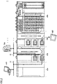
- Fig. 2 is a diagram schematically illustrating an example of a hardware configuration of a control system 1 according to the present embodiment.
- control system 1 includes a control device 100, a relay device 200, at least one function unit 400, and a power supply unit 450.
- Control device 100 and relay device 200 are connected over any desired data communication channel (for example, PCI Express (registered trademark), Ethernet (registered trademark), or the like).
- Control device 100 and at least one function unit 400 are connected over an internal bus.
- Control device 100 performs a main process in control system 1. Control device 100 performs control calculation for controlling the control object in accordance with a required specification designed as desired. In the configuration example illustrated in Fig. 2 , control device 100 includes at least one communication port, and one of the communication ports is communicatively connected to at least one human machine interface (HMI) 600.
- HMI human machine interface
- Relay device 200 is connected to control device 100 and is responsible for communicating with other devices.
- relay device 200 includes at least one communication port, and one of the communication ports is communicatively connected to a support device 500 over a network 11, and another one of the communication ports is communicatively connected to at least one external device 700 over a network 12.
- Function unit 400 provides various functions for allowing control system 1 to perform control on various control objects.
- Function unit 400 typically includes an I/O unit, a safety I/O unit, a communication unit, a motion controller unit, a temperature control unit, a pulse counter unit, and the like.
- the I/O unit include a digital input (DI) unit, a digital output (DO) unit, an analog input (AI) unit, an analog output (AO) unit, a pulse catch input unit, and a composite unit that is a combination of a plurality of types of units.
- DI digital input
- DO digital output
- AI analog input
- AO analog output
- a pulse catch input unit and a composite unit that is a combination of a plurality of types of units.
- Power supply unit 450 supplies power of a predetermined voltage to each unit constituting control system 1.
- Fig. 3 is a table showing variations of the configuration of the control system according to the present embodiment.
- the function units including control unit 100a, relay unit 200a, request source 500a, reception unit 230a, authentication unit 240a, and access management unit 250a in the application example described with reference to Fig. 1 may each belong to any one of control device 100, relay device 200, and support device 500 in control system 1 illustrated in Fig. 2 .
- control device 100 has the function of control unit 100a
- relay device 200 has the function of relay unit 200a
- the function of reception unit 230a the function of authentication unit 240a
- the function of access management unit 250a the function of access management unit 250a
- support device 500 has the function of request source 500a.
- control device 100 has the function of control unit 100a and the function of request source 500a
- relay device 200 has the function of relay unit 200a, the function of reception unit 230a, the function of authentication unit 240a, and the function of access management unit 250a.
- control device 100 and relay device 200 are integrated into a single device in the control system according to pattern 1. That is, in the control system according to pattern 3, the device in which control device 100 and relay device 200 are integrated has the function of control unit 100a, the function of relay unit 200a, the function of reception unit 230a, the function of authentication unit 240a, and the function of access management unit 250a, and support device 500 has the function of request source 500a.
- control device 100 and relay device 200 have the function of control unit 100a, the function of relay unit 200a, the function of request source 500a, the function of reception unit 230a, the function of authentication unit 240a, and the function of access management unit 250a.
- control device 100 includes, as main components, a processor 102 such as a central processing unit (CPU) or a graphical processing unit (GPU), a chipset 104, a primary storage device 106, a secondary storage device 108, a communication controller 110, a memory card interface 114, network controllers 144, 146, and an internal bus controller 122.
- processor 102 such as a central processing unit (CPU) or a graphical processing unit (GPU)
- chipset 104 such as a central processing unit (CPU) or a graphical processing unit (GPU)
- Processor 102 reads various programs stored in secondary storage device 108, loads the programs into primary storage device 106, and executes the programs to enable various functions.
- Chipset 104 serves as an interface for exchanging data between processor 102 and each component to enable the entire function of control device 100.
- Primary storage device 106 includes a volatile storage device such as a dynamic random access memory (DRAM) or a static random access memory (SRAM).
- DRAM dynamic random access memory
- SRAM static random access memory
- Secondary storage device 108 includes, for example, a non-volatile storage device such as a hard disk drive (HDD) and a solid state drive (SSD). Secondary storage device 108 stores not only a system program 1802 that provides basic functions but also a user program 1804 created as desired by the user. User program 1804 runs on a runtime environment provided by system program 1802.
- HDD hard disk drive
- SSD solid state drive
- Communication controller 110 is responsible for exchanging data with relay device 200.
- communication controller 110 for example, a communication chip compatible with PCI Express (registered trademark), Ethernet (registered trademark), or the like may be used.
- Memory card interface 114 is configured to receive a memory card 115 in a detachable manner and is capable of writing data such as a user program or various settings to memory card 115 or reading data such as a user program or various settings from memory card 115.
- Each of network controllers 144, 146 is responsible for exchanging data with any device over the network.
- Network controllers 144, 146 may use an industrial network protocol such as EtherCAT (registered trademark), EtherNet/IP (registered trademark), DeviceNet (registered trademark), or CompoNet (registered trademark).
- Network controller 144 is responsible for exchanging data with at least one field device 800.
- Field device 800 includes a sensor and a detector that collect, from the control object, various types of information necessary for control calculation, an actuator that imparts some action to the control object, or the like.
- Field device 800 includes a robot that gives some external action to the workpiece, a conveyor that conveys the workpiece, an I/O unit that exchanges signals with the sensor and the actuator arranged in the field, and the like.
- Network controller 146 is responsible for exchanging data with HMI 600.
- HMI 600 presents various types of information obtained by control calculation in control system 1 to the user (operator), and generates an internal command or the like directed to control system 1 in response to an operation made by the user.
- Internal bus controller 122 is responsible for exchanging data with at least one function unit 400.
- a communication protocol unique to a manufacturer may be used, or a communication protocol that is the same as or compliant with any of the industrial network protocols may be used.
- Fig. 4 illustrates the configuration example where processor 102 executes a program to provide necessary functions, but some or all of the functions thus provided may be implemented by a dedicated hardware circuit (for example, an application specific integrated circuit (ASIC), a field-programmable gate array (FPGA), or the like).
- a core part of control device 100 may be implemented by hardware having a general-purpose architecture (for example, an industrial personal computer based on a general-purpose personal computer).
- a plurality of operating systems (OSs) having different uses may be executed in parallel using a virtualization technology, and a necessary application may be executed on each OS.
- OSs operating systems
- Fig. 5 is a diagram schematically illustrating an example of a hardware configuration of relay device 200 according to the present embodiment.
- relay device 200 includes, as main components, a processor 202 such as a CPU or a GPU, a chipset 204, a primary storage device 206, a secondary storage device 216, a communication controller 210, a memory card interface 214, and network controllers 208, 220.
- Processor 202 reads various programs stored in secondary storage device 216, loads the programs into primary storage device 206, and executes the programs to enable various functions.
- Chipset 204 serves as an interface for exchanging data between processor 202 and each component to enable the entire function of relay device 200.
- Secondary storage device 216 stores not only a system program that provides basic functions but also various programs that run on a runtime environment provided by the system program.
- secondary storage device 216 stores an access management program 2802 for performing the access management process including the reception step, the authentication step, the access management step, and the like illustrated in Fig. 1 .
- Secondary storage device 216 further stores an access management list 2804 that is referred to in the access management step, authentication data 2806 that is referred to in the authentication step, and a filter log 2808.
- Access management list 2804 will be described with reference to Figs. 6 and 7 .
- Authentication data 2806 is data used in authentication of the validity of the request source, and contains, as described above, an ID and a password used in password authentication, physical features of the user used in biometric authentication, an electronic certificate used in certificate authentication, key data used in key authentication, or the like.
- Filter log 2808 is a log of access from external device 700 to control device 100, and contains specific information such as an access history indicating success or failure in access from external device 700 to control device 100. This allows relay device 200 to keep a log of access from external device 700 to control device 100, thereby allowing relay device 200 to easily manage access from external device 700 to control device 100.
- Communication controller 210 is responsible for exchanging data with control device 100.
- communication controller 210 for example, a communication chip compatible with PCI Express, Ethernet, or the like may be used as with communication controller 110 of control device 100.
- Memory card interface 214 is configured to receive a memory card 215 in a detachable manner and is capable of writing data such as a user program or various settings to memory card 215 or reading data such as a user program or various settings from memory card 215.
- Each of network controllers 208, 220 is responsible for exchanging data with any device over the network.
- Each of network controllers 208, 220 may use a general-purpose network protocol such as Ethernet (registered trademark).
- Ethernet registered trademark
- support device 500 and external device 700 are connected to relay device 200 over the network.
- Fig. 5 illustrates a configuration example where processor 202 executes a program to provide necessary functions, but some or all of the functions thus provided may be implemented by a dedicated hardware circuit (for example, an ASIC or an FPGA).
- a core part of relay device 200 may be implemented by hardware having a general-purpose architecture (for example, an industrial personal computer based on a general-purpose personal computer).
- a plurality of OSs having different uses may be executed in parallel using a virtualization technology, and a necessary application may be executed on each OS.
- Fig. 6 is a table showing a port management list included in access management list 2804 according to the present embodiment.
- a network protocol such as object linking and embedding for process control unified architecture (OPCUA) is used.
- OCUA process control unified architecture
- a network protocol such as Ethernet is used.
- a device manufacturer-specific network protocol such as FINS is used.
- a management mode 1 is a mode indicating a development phase of a system including control device 100. In the development phase of the system, communications through all ports 1 to 3 are used, so that it is necessary to permit communications through all ports 1 to 3 in management mode 1.
- a management mode 2 is a mode indicating an operation phase of the system including control device 100. In the operation phase of the system, communications through only port 1 are used, so that it is necessary to establish communications only through port 1 in management mode 2.
- a management mode 3 is a mode indicating a maintenance phase of the system including control device 100. In the maintenance phase of the system, communications through port 1 and port 2 are used, so that it is necessary to establish communications through port 1 and port 2 in management mode 3.
- control system 1 when the restriction level of access from external device 700 to control device 100 is controlled by the access management process, access from external device 700 to control device 100 is permitted through a port enabled in accordance with the type of the current management mode. For example, in the access management step, in management mode 1, access from external device 700 to control device 100 through all ports 1 to 3 is permitted, in management mode 2, access from external device 700 to control device 100 only through port 1 is permitted, while access from external device 700 to control device 100 through ports 2 and 3 is prohibited, and in management mode 3, access from external device 700 to control device 100 through ports 1 and 2 is permitted, while access from external device 700 to control device 100 through port 3 is prohibited.
- relay device 200 controls the restriction level of access from external device 700 to control device 100 in accordance with the type of the management mode, is it possible to improve security while taking the operation aspect into consideration.
- Fig. 7 is a table showing an IP address management list included in access management list 2804 according to the present embodiment.
- the IP address management list includes a so-called blacklist.
- the blacklist explicitly specifies a specific IP address from which access is prohibited.
- access management list 2804 may include, rather than such a blacklist, a whitelist that explicitly specifies a specific IP address from which access is permitted.
- control system 1 when the restriction level of access from external device 700 to control device 100 is controlled by the access management process, access from external device 700 to control device 100 is permitted through a port enabled in accordance with the type of the current management mode based on the port management list, while access from an IP address specified in the IP address management list is prohibited.
- Fig. 8 is a diagram schematically illustrating an example of a hardware configuration of support device 500 according to the present embodiment.
- support device 500 is implemented by hardware having a general-purpose architecture (for example, a general-purpose personal computer).
- a general-purpose architecture for example, a general-purpose personal computer.
- support device 500 includes a processor 502 such as a CPU or a GPU, a primary storage device 504, an input unit 506, an output unit 508, a secondary storage device 510, an optical drive 512, and a network controller 520.
- processor 502 such as a CPU or a GPU
- primary storage device 504 such as a CPU or a GPU
- input unit 506 such as a CPU or a GPU
- an input unit 506 such as a CPU or a GPU
- Processor 502 reads a program stored in secondary storage device 510, loads the program into primary storage device 504, and executes the program to enable various functions.
- Secondary storage device 510 stores not only an OS 5102 for implementing basic functions but also an access management application 5104 as a program for the access management process performed by relay device 200 and authentication data 5106.
- access management application 5104 for example, a process of starting (kicking off) the access management process when support device 500 functions as request source 500a illustrated in Fig. 1 is defined, and when access management application 5104 is executed, the authentication request is transmitted from support device 500 to relay device 200.
- Authentication data 5106 is data used for authentication of the validity of the user of support device 500 serving as the request source, and contains, as described above, an ID and a password used in password authentication, physical features of the user used in biometric authentication, an electronic certificate used in certificate authentication, key data used in key authentication, or the like.
- Input unit 506 includes a keyboard, a mouse, or the like, and receives a user operation.
- Output unit 508 includes a display, various indicators, a printer, or the like, and outputs a processing result and the like received from processor 502.
- Support device 500 includes optical drive 512 so as to allow a program stored in a computer-readable recording medium 514 (for example, an optical recording medium such as a digital versatile disc (DVD)) that stores instructions in a non-transitory manner to be read and installed in secondary storage device 510 or the like.
- a computer-readable recording medium 514 for example, an optical recording medium such as a digital versatile disc (DVD)
- DVD digital versatile disc
- support device 500 may be installed via computer-readable recording medium 514, or may be downloaded from a server device or the like on a network and then installed. Functions provided by support device 500 according to the present embodiment may be implemented via some of the modules provided by the OS.
- Network controller 520 is responsible for exchanging data with any device over the network.
- Network controller 520 may use a general-purpose network protocol such as Ethernet (registered trademark).
- Ethernet registered trademark
- relay device 200 is connected to support device 500 over the network.
- Fig. 8 illustrates a configuration example where processor 502 executes a program to provide functions necessary for support device 500, but some or all of the functions thus provided may be implemented by a dedicated hardware circuit (for example, an ASIC or an FPGA).
- a dedicated hardware circuit for example, an ASIC or an FPGA.
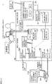
- Fig. 9 is a diagram schematically illustrating an example of the access management process in control system 1 according to the present embodiment. Note that, as described above, Figs. 9 to 11 illustrate an example of the access management process performed in control system 1 according to pattern 1 shown in Fig. 3 .
- relay device 200 Upon receipt of the authentication request from support device 500 through a communication port 2081 included in network controller 208, relay device 200 compares authentication data 5106 from support device 500 with authentication data 2806 held by relay device 200 for authentication of the validity of the user of support device 500 serving as the request source.
- the authentication of the validity of the user of support device 500 is concealed by VPN authentication, so that security is ensured. Such an authentication process is performed in accordance with access management program 2802.
- relay device 200 Having authenticated the validity of the user of support device 500, relay device 200 notifies support device 500 of an authentication permission. This establishes communications between support device 500 and relay device 200 with security ensured by VPN authentication.
- Support device 500 requests relay device 200 to enable access from external device 700 to control device 100 in accordance with access management application 5104.
- relay device 200 enables access from external device 700 to relay device 200 through a communication port 2201 included in network controller 220 by the access management process in accordance with access management program 2802.
- relay device 200 controls, in accordance with access management program 2802, network controller 220 based on access management list 2804 so as to permit only access through a communication port enabled in accordance with the management mode requested by support device 500 and to prohibit access through the other communication ports.
- relay device 200 Since the restriction level of access from the external device 700 to control device 100 is controlled by relay device 200 that relays access from external device 700 to control device 100 when the validity of the user of support device 500 serving as the request source is authenticated by relay device 200, it is possible to improve security without changing external device 700 that runs on a legacy application.
- Fig. 10 is a sequence diagram illustrating an example of an access management method in control system 1 according to the present embodiment.
- Fig. 10 illustrates a sequence in which, in support device 500, a corresponding process proceeds when processor 502 executes access management application 5104, in relay device 200, a corresponding process proceeds when processor 202 executes access management program 2802, and in external device 700, a corresponding process proceeds when a processor (not illustrated) included in external device 700 executes a data communication application 7010.
- processor 202 executes access management program 2802 to enable the function of reception unit 230a, the function of authentication unit 240a, and the function of access management unit 250a illustrated in Fig. 1 .
- support device 500 serving as the request source issues the authentication request to relay device 200 (S51).
- relay device 200 Upon receipt of the authentication request from support device 500 (S21), relay device 200 authenticates the validity of the user of support device 500. Having authenticated the validity of the user of support device 500, relay device 200 notifies support device 500 of the authentication permission (S22). This establishes communications between support device 500 and relay device 200 with security ensured by VPN authentication.
- relay device 200 instructs, based on access management list 2804, network controller 220 to enable access through port ⁇ in accordance with selected management mode X (S24). Accordingly, network controller 220 of relay device 200 sets access through port ⁇ enabled in accordance with selected management mode X (S25).
- external device 700 can acquire various data from control device 100 via relay device 200. For example, when external device 700 makes an access response to port ⁇ before access through port ⁇ is enabled (S71), no response is made from network controller 220 (S23), but when external device 700 makes an access response to port ⁇ after access through port ⁇ is enabled (S72), a response is made from network controller 220 (S26).
- access management program 2802 Since the restriction level of access from external device 700 to control device 100 is controlled by access management program 2802 for managing access from external device 700 to control device 100 when the validity of the user of support device 500 serving as the request source is authenticated by access management program 2802, it is possible to improve security without changing external device 700 that runs on a legacy application.
- Fig. 11 is a schematic diagram illustrating an example of a case where an incident occurs in the access management process in control system 1 according to the present embodiment.
- Fig. 11 it is assumed that an incident occurs with access from another external device 900 to control device 100 permitted. At this time, it is assumed that the IP address of another external device 900 is not included in the blacklist in access management list 2804 shown in Fig. 7 .
- an image indicating that the incident has occurred is displayed on HMI 600. Further, on HMI 600, the IP address of another external device 900 that has caused the incident and an image for prompting for selection of whether to disable access from external device 900 are displayed.
- support device 500 requests relay device 200 to disable access from another external device 900 to control device 100.
- relay device 200 updates the blacklist in access management list 2804 to add, to the blacklist, the IP address of another external device 900 that has caused the incident. Thereafter, access from another external device 900 to control device 100 is prohibited.
- control system 1 it is possible to improve security with access management list 2804 used for controlling the restriction level of access from external device 700 to control device 100. Furthermore, since access management list 2804 is updated when an incident occurs in access from another external device 900 to control device 100, it is possible to improve security with access management list 2804 with consideration given to the occurrence of the incident.
- Fig. 12 is a diagram schematically illustrating an example of an access management process in a control system 1000 according to another embodiment. Note that, as described above, Fig. 12 illustrate an example of the access management process performed in control system 1000 according to pattern 2 shown in Fig. 3 .
- Control system 1000 according to pattern 2 illustrated in Fig. 12 is different from control system 1 according to pattern 1 illustrated in Fig. 9 in that control device 100 serves as the request source. Specifically, first, in control device 100 serving as the request source, communication controller 110 issues the authentication request to communication controller 210 of relay device 200 in accordance with an instruction from user program 1804. At this time, authentication data is transmitted from control device 100 to relay device 200.
- relay device 200 Upon receipt of the authentication request from control device 100 via communication controller 210, relay device 200 authenticates the validity of control device 100 serving as the request source by, for example, comparing the authentication data from control device 100 with authentication data 2806 held by relay device 200.
- the authentication of the validity of control device 100 is concealed by the VPN authentication, so that security is ensured. Such an authentication process is performed in accordance with access management program 2802.
- relay device 200 Having authenticated the validity of control device 100, relay device 200 notifies control device 100 of the authentication permission. This establishes communications between control device 100 and relay device 200 with security ensured by VPN authentication.
- Relay device 200 enables access from external device 700 to relay device 200 through communication port 2201 included in network controller 220 by the access management process in accordance with access management program 2802. At this time, relay device 200 controls, in accordance with access management program 2802, network controller 220 based on access management list 2804 so as to permit only access through a communication port enabled in accordance with the management mode requested by control device 100 and to prohibit access through the other communication ports.
- the present embodiment includes the following disclosure.
- a control system (1a, 1) configured to control a control object, the control system (1a, 1) including:
- control system according to configuration 2, wherein the authentication unit authenticates the validity of the request source with communications from the request source concealed.
- control system according to any one of configurations 1 to 4, wherein the relay unit keeps a log (2808) of access from the external device to the control unit.
- control system according to any one of configurations 1 to 5, wherein the access management unit controls, based on a list (2804) for controlling the restriction level of access from the external device to the control unit, the restriction level of access from the external device to the control unit when the validity of the request source is authenticated by the authentication unit.
- control system according to configuration 6, wherein the list is updated when an incident occurs in access from the external device to the control unit.
- a relay device (200a, 200) configured to relay access from an external device (700a, 700) to a control device (100a, 100) configured to control a control object, the relay device (200a, 200) including:
- An access management program (2802) configured to manage access from an external device (700a, 700) to a control device (100a, 100) configured to control a control object, the access management program (2802) causing a computer (202) to execute:
- Control system 1 can improve security without changing external device 700 that runs on a legacy application.
Landscapes
- Engineering & Computer Science (AREA)
- Physics & Mathematics (AREA)
- General Physics & Mathematics (AREA)
- Theoretical Computer Science (AREA)
- Automation & Control Theory (AREA)
- General Health & Medical Sciences (AREA)
- Bioethics (AREA)
- Computer Hardware Design (AREA)
- Computer Security & Cryptography (AREA)
- Software Systems (AREA)
- General Engineering & Computer Science (AREA)
- Health & Medical Sciences (AREA)
- Small-Scale Networks (AREA)
- Programmable Controllers (AREA)
Abstract
Description
- The present invention relates to a control system, a relay device, and an access management program, and more specifically, to a control system that controls a control object, a relay device that relays access from an external device to a control device that controls the control object, and an access management program for managing access from the external device to the control device that controls the control object.
- Machines and equipment used in a production site using factory automation (FA) are typically controlled by a control device such as a programmable controller (programmable logic controller; hereinafter, also referred to as a "PLC"). Such a control device is configured to be able to communicate with an external device.
- For example,
Japanese Patent Laying-Open No. 2001-175615 - PTL 1:
Japanese Patent Laying-Open No. 2001-175615 - As in the production system disclosed in
PTL 1, in the field of FA, a system configured to allow access from an external device to a control device over a network is available, but a secure state is not necessarily ensured for communications between the control device and the external device. In this regard, in the field of information technology (IT), a technology for improving security such as virtual private network (VPN) is available. In the field of FA, however, such an external device runs on a so-called legacy application in many cases, and it is not realistic to implement a new security technology into such an old-fashioned system because the system may need to be significantly changed, which requires a significant increase in cost or a temporary halt on the operation of the production site. - It is therefore an object of the present invention to solve the above-described problems and to provide a technique for improving security without changing a legacy application.
- Provided according to an example of the present disclosure is a control system configured to control a control object. The control system includes a control unit configured to control the control object and communicate with an external device, and a relay unit configured to relay access from the external device to the control unit. The relay unit includes a reception unit configured to receive an authentication request from a request source, an authentication unit configured to authenticate validity of the request source upon receipt of the authentication request by the reception unit, and an access management unit configured to control a restriction level of access from the external device to the control unit when the validity of the request source is authenticated by the authentication unit.
- According to this disclosure, since the restriction level of access from the external device to the control unit is controlled by the relay unit that relays access from the external device to the control unit when the validity of the request source is authenticated by the relay unit, it is possible to improve security without changing the external device that runs on a legacy application.
- In the above disclosure, the authentication unit authenticates the validity of the request source based on predetermined authentication data.
- According to this disclosure, it is possible to further improve security of the authentication of the validity of the request source performed by the relay unit using the predetermined authentication data.
- In the above disclosure, the authentication unit authenticates the validity of the request source with communications from the request source concealed.
- According to this disclosure, it is possible to further improve security of the authentication of the validity of the request source performed by the relay unit by virtue of the concealed communications.
- In the above disclosure, the control unit communicates with the external device in accordance with a type of a management mode, and the access management unit controls the restriction level of access from the external device in accordance with the type of the management mode.
- According to this disclosure, since the relay unit controls the restriction level of access from the external device to the control unit in accordance with the type of the management mode, is it possible to improve security while taking the operation aspect into consideration.
- In the above disclosure, the relay unit keeps a log of access from the external device to the control unit.
- According to this disclosure, since it is possible to keep the log of access from the external device to the control unit, access from the external device to the control unit is easily managed.
- In the above disclosure, the access management unit controls, based on a list for controlling the restriction level of access from the external device to the control unit, the restriction level of access from the external device to the control unit when the validity of the request source is authenticated by the authentication unit.
- According to this disclosure, it is possible to improve security with the list for controlling the restriction level of access from the external device to the control unit.
- In the above disclosure, the list is updated when an incident occurs in access from the external device to the control unit.
- According to this disclosure, it is possible to improve security with the list with consideration given to the occurrence of the incident.
- Provided according to another example of the present disclosure is a relay device configured to relay access from an external device to a control device configured to control a control object. The relay device includes a reception unit configured to receive an authentication request from a request source, an authentication unit configured to authenticate validity of the request source upon receipt of the authentication request by the reception unit, and an access management unit configured to control a restriction level of access from the external device to the control device when the validity of the request source is authenticated by the authentication unit.
- According to this disclosure, since the restriction level of access from the external device to the control device is controlled by the relay device that relays access from the external device to the control device when the validity of the request source is authenticated by the relay device, it is possible to improve security without changing the external device that runs on a legacy application.
- Provided according to another example of the present disclosure is an access management program configured to manage access from an external device to a control device configured to control a control object. The access management program causes a computer to execute a reception step of receiving an authentication request from a request source, an authentication step of authenticating validity of the request source upon receipt of the authentication request in the reception step, and an access management step of controlling a restriction level of access from the external device to the control device when the validity of the request source is authenticated in the authentication step.
- According to this disclosure, since the restriction level of access from the external device to the control device is controlled by the access management program for managing access from the external device to the control device when the validity of the request source is authenticated by the access management program, it is possible to improve security without changing the external device that runs on a legacy application.
-
-
Fig. 1 is a schematic diagram for describing a control system according to the present embodiment. -
Fig. 2 is a diagram schematically illustrating an example of a hardware configuration of the control system according to the present embodiment. -
Fig. 3 is a table showing variations of the configuration of the control system according to the present embodiment. -
Fig. 4 is a diagram schematically illustrating an example of a hardware configuration of a control device according to the present embodiment. -
Fig. 5 is a diagram schematically illustrating an example of a hardware configuration of a relay device according to the present embodiment. -
Fig. 6 is a table showing a port management list included in an access management list according to the present embodiment. -
Fig. 7 is a table showing an IP address management list included in the access management list according to the present embodiment. -
Fig. 8 is a diagram schematically illustrating an example of a hardware configuration of a support device according to the present embodiment. -
Fig. 9 is a diagram schematically illustrating an example of an access management process in the control system according to the present embodiment. -
Fig. 10 is a sequence diagram illustrating the example of the access management process in the control system according to the present embodiment. -
Fig. 11 is a diagram schematically illustrating an example of a case where an incident occurs in the access management process in the control system according to the present embodiment. -
Fig. 12 is a diagram schematically illustrating an example of an access management process in a control system according to another embodiment. - Embodiments of the present invention will be described in detail with reference to the drawings. Note that the same or corresponding parts in the drawings are denoted by the same reference numerals, and no redundant description will be given of such parts.
- First, an example of a case to which the present invention is applied will be described.
-
Fig. 1 is a schematic diagram for describing acontrol system 1a according to the present embodiment. As illustrated inFig. 1 ,control system 1a includes acontrol unit 100a, anexternal device 700a, and arelay unit 200a. -
Control unit 100a is configured to control a control object and communicate withexternal device 700a viarelay unit 200a.Control unit 100a corresponds to the function of an industrial controller that controls control objects such as various types of equipment or apparatus, and typically corresponds to a function included in a programmable logic controller (PLC).Control unit 100a controls the control object (not illustrated) in accordance with a user program designed in advance. Examples of the control object include various industrial equipment for automating a production process used in the field of FA. Specifically, the examples of the control object include a robot controller, an arm robot controlled by a robot controller, a servomotor controlled by a servo driver, a visual sensor configured to take an image of a workpiece, and other equipment used in a production process. -
External device 700a is configured to be able to communicate withcontrol unit 100a viarelay unit 200a.External device 700a collects, fromcontrol unit 100a, and accumulates various data. The various data accumulated byexternal device 700a contains data on the control of the control object performed bycontrol unit 100a. For example, the various data accumulated byexternal device 700a contains information on traceability measured from the workpiece. -
Relay unit 200a relays access fromexternal device 700a to controlunit 100a. Specifically,relay unit 200a includes acommunication controller 210a and anetwork controller 220a including aport 2201a.Communication controller 210a is responsible for exchanging data with acommunication controller 110a included incontrol unit 100a. Data acquired fromcontrol unit 100a viacommunication controller 210a is transmitted toexternal device 700a viaport 2201a ofnetwork controller 220a. - Note that
control unit 100a andrelay unit 200a may be included in different devices, or may be included in the same device. For example, a PLC, which is an example of the device includingcontrol unit 100a, may have the function ofcontrol unit 100a but not the function ofrelay unit 200a, or may have the function ofcontrol unit 100a and the function ofrelay unit 200a. - In
control system 1a having such a configuration,external device 700a accessescontrol unit 100a viarelay unit 200a to collect, fromcontrol unit 100a, and accumulates various data. Herein, in the field of FA to whichcontrol system 1a belongs,external device 700a runs on a so-called legacy application in many cases. For this reason, in a case where a relatively new security technology such as VPN is implemented in order to ensure communications betweenexternal device 700a andcontrol unit 100a used in the related art are maintained in a secure state, the system may need to be significantly changed in its entirety, which requires a significant increase in cost or a temporary halt on the operation of the production site. - Therefore, according to the present embodiment, a technique for improving security without changing a legacy application has been proposed.
- Specifically,
relay unit 200a includes areception unit 230a, anauthentication unit 240a, and anaccess management unit 250a.Reception unit 230a receives an authentication request from arequest source 500a.Authentication unit 240a authenticates the validity ofrequest source 500a upon receipt of the authentication request byreception unit 230a.Access management unit 250a controls a restriction level of access fromexternal device 700a to controlunit 100a whenauthentication unit 240a authenticates the validity ofrequest source 500a. - Request
source 500a is a function unit that starts (kicks off) a series of processes of requesting access fromexternal device 700a to controlunit 100a. Requestsource 500a may be included in a device different from a device includingcontrol unit 100a, or may be included in the same device as a device includingcontrol unit 100a. For example, a PLC, which is an example of the device includingcontrol unit 100a, may have the function ofcontrol unit 100a but not the function ofrequest source 500a, or may have the function ofcontrol unit 100a and the function ofrequest source 500a. - The "validity of the request source" includes, for example, a property that request
source 500a may be permitted to control the restriction level of access fromexternal device 700a to controlunit 100a. In other words, when the validity ofrequest source 500a is authenticated,request source 500a is permitted to control the restriction level of access fromexternal device 700a to controlunit 100a. -
Authentication unit 240a authenticates the validity ofrequest source 500a based on predetermined authentication data. For example, as a method of authenticating the validity ofrequest source 500a byauthentication unit 240a, any authentication may be applied as long as the authentication can ensure security, such as password authentication using an ID and a password of a user, biometric authentication using physical features such as a fingerprint or a face image of the user, certificate authentication using an electronic certificate issued by a certificate authority, or key authentication using key data such as a private key/public key or a common key. That is, the "predetermined authentication data" contains an ID and a password used in password authentication, physical features of the user used in biometric authentication, an electronic certificate used in certificate authentication, key data used in key authentication, or the like. Further,authentication unit 240a authenticates the validity ofrequest source 500a with communications fromrequest source 500a concealed. As a representative concealment method, a technique for improving security such as VPN may be applied. - The "restriction level of access" is a degree indicating that access from
external device 700a to controlunit 100a is in a prohibited state or a permitted state. For example, when access fromexternal device 700a to controlunit 100a is controlled from the prohibited state to the permitted state, the restriction level of access goes up, and when access fromexternal device 700a to controlunit 100a is controlled from the permitted state to the prohibited state, the restriction level of access goes down. - Further, the restriction of access from
external device 700a to controlunit 100a is imposed on not only oneport 2201a but also each of a plurality of ports. For example, for access fromexternal device 700a to controlunit 100a, when access to a first port is controlled from the prohibited state to the permitted state, and access to a second port is controlled from the prohibited state to the permitted state, the restriction level of access goes down. When access to the first port is controlled from the prohibited state to the permitted state, and access to the second port is maintained in the permitted state or the prohibited state, the restriction level of access goes down. When access to the first port is maintained in the permitted state or the prohibited state, and access to the second port is controlled from the prohibited state to the permitted state, the restriction level of access goes down. On the other hand, for access fromexternal device 700a to controlunit 100a, when access to the first port is controlled from the permitted state to the prohibited state, and access to the second port is controlled from the permitted state to the prohibited state, the restriction level of access goes up. When access to the first port is controlled from the permitted state to the prohibited state, and the access to the second port is maintained in the permitted state or the prohibited state, the restriction level of access goes up. When access to the first port is maintained in the permitted state or the prohibited state, and access to the second port is controlled from the permitted state to the prohibited state, the restriction level of access goes up. - That is, when access from
external device 700a to controlunit 100a is controlled to be further restricted, the restriction level of access goes up, and when access fromexternal device 700a to controlunit 100a is controlled to be less restricted, the restriction level of access goes down. -
Relay unit 200a configured as described above operates as follows. Specifically,relay unit 200a causesreception unit 230a to receive the authentication request fromrequest source 500a. Such a process is referred to as a reception step. Next,relay unit 200a causesauthentication unit 240a to authenticate the validity ofrequest source 500a. Such a process is referred to as an authentication step.Relay unit 200a causesaccess management unit 250a to control the restriction level of access fromexternal device 700a to controlunit 100a when the validity ofrequest source 500a is authenticated. Such a process is referred to as an access management step. Note that the series of processes of controlling, byrelay unit 200a, the restriction level of access fromexternal device 700a to controlunit 100a is hereinafter also referred to as an access management process. - In
control system 1a, since the restriction level of access fromexternal device 700a to controlunit 100a is controlled byrelay unit 200a that relays access fromexternal device 700a to controlunit 100a when the validity ofrequest source 500a is authenticated byrelay unit 200a, it is possible to improve security without changingexternal device 700a that runs on a legacy application. - Note that the number of
external devices 700a is not limited to one, and a plurality ofexternal devices 700a may be provided. That is, the plurality ofexternal devices 700a may eachaccess control unit 100a. The restriction level of access may be controlled for each of the plurality ofexternal devices 700a. -
Control unit 100a,relay unit 200a, requestsource 500a,reception unit 230a,authentication unit 240a, andaccess management unit 250a described above may be implemented by a computer or a circuit board. An example of a case where such function units are implemented in a device will be described. -
Fig. 2 is a diagram schematically illustrating an example of a hardware configuration of acontrol system 1 according to the present embodiment. As illustrated inFig. 2 ,control system 1 includes acontrol device 100, arelay device 200, at least onefunction unit 400, and apower supply unit 450. -
Control device 100 andrelay device 200 are connected over any desired data communication channel (for example, PCI Express (registered trademark), Ethernet (registered trademark), or the like).Control device 100 and at least onefunction unit 400 are connected over an internal bus. -
Control device 100 performs a main process incontrol system 1.Control device 100 performs control calculation for controlling the control object in accordance with a required specification designed as desired. In the configuration example illustrated inFig. 2 ,control device 100 includes at least one communication port, and one of the communication ports is communicatively connected to at least one human machine interface (HMI) 600. -
Relay device 200 is connected to controldevice 100 and is responsible for communicating with other devices. In the configuration example illustrated inFig. 2 ,relay device 200 includes at least one communication port, and one of the communication ports is communicatively connected to asupport device 500 over anetwork 11, and another one of the communication ports is communicatively connected to at least oneexternal device 700 over anetwork 12. -
Function unit 400 provides various functions for allowingcontrol system 1 to perform control on various control objects.Function unit 400 typically includes an I/O unit, a safety I/O unit, a communication unit, a motion controller unit, a temperature control unit, a pulse counter unit, and the like. Examples of the I/O unit include a digital input (DI) unit, a digital output (DO) unit, an analog input (AI) unit, an analog output (AO) unit, a pulse catch input unit, and a composite unit that is a combination of a plurality of types of units. -
Power supply unit 450 supplies power of a predetermined voltage to each unit constitutingcontrol system 1. -
Fig. 3 is a table showing variations of the configuration of the control system according to the present embodiment. The function units includingcontrol unit 100a,relay unit 200a, requestsource 500a,reception unit 230a,authentication unit 240a, andaccess management unit 250a in the application example described with reference toFig. 1 may each belong to any one ofcontrol device 100,relay device 200, andsupport device 500 incontrol system 1 illustrated inFig. 2 . - As illustrated in
Fig. 3 , in a control system according to apattern 1,control device 100 has the function ofcontrol unit 100a,relay device 200 has the function ofrelay unit 200a, the function ofreception unit 230a, the function ofauthentication unit 240a, and the function ofaccess management unit 250a, andsupport device 500 has the function ofrequest source 500a. - In a control system according to a
pattern 2,control device 100 has the function ofcontrol unit 100a and the function ofrequest source 500a, andrelay device 200 has the function ofrelay unit 200a, the function ofreception unit 230a, the function ofauthentication unit 240a, and the function ofaccess management unit 250a. - In a control system according to a
pattern 3,control device 100 andrelay device 200 are integrated into a single device in the control system according topattern 1. That is, in the control system according topattern 3, the device in whichcontrol device 100 andrelay device 200 are integrated has the function ofcontrol unit 100a, the function ofrelay unit 200a, the function ofreception unit 230a, the function ofauthentication unit 240a, and the function ofaccess management unit 250a, andsupport device 500 has the function ofrequest source 500a. - In a control system according to a
pattern 4, the device in whichcontrol device 100 andrelay device 200 are integrated has the function ofcontrol unit 100a, the function ofrelay unit 200a, the function ofrequest source 500a, the function ofreception unit 230a, the function ofauthentication unit 240a, and the function ofaccess management unit 250a. - Note that, in the present embodiment, the function of the control system according to
pattern 1 will be described using an example illustrated inFigs. 9 to 11 , and the function of the control system according topattern 2 will be described using an example illustrated inFig. 12 . -
Fig. 4 is a diagram schematically illustrating an example of a hardware configuration of the control device according to the present embodiment. As illustrated inFig. 4 ,control device 100 includes, as main components, aprocessor 102 such as a central processing unit (CPU) or a graphical processing unit (GPU), achipset 104, aprimary storage device 106, asecondary storage device 108, acommunication controller 110, amemory card interface 114,network controllers -
Processor 102 reads various programs stored insecondary storage device 108, loads the programs intoprimary storage device 106, and executes the programs to enable various functions. -
Chipset 104 serves as an interface for exchanging data betweenprocessor 102 and each component to enable the entire function ofcontrol device 100. -
Primary storage device 106 includes a volatile storage device such as a dynamic random access memory (DRAM) or a static random access memory (SRAM). -
Secondary storage device 108 includes, for example, a non-volatile storage device such as a hard disk drive (HDD) and a solid state drive (SSD).Secondary storage device 108 stores not only asystem program 1802 that provides basic functions but also auser program 1804 created as desired by the user.User program 1804 runs on a runtime environment provided bysystem program 1802. -
Communication controller 110 is responsible for exchanging data withrelay device 200. Ascommunication controller 110, for example, a communication chip compatible with PCI Express (registered trademark), Ethernet (registered trademark), or the like may be used. -
Memory card interface 114 is configured to receive amemory card 115 in a detachable manner and is capable of writing data such as a user program or various settings tomemory card 115 or reading data such as a user program or various settings frommemory card 115. - Each of
network controllers Network controllers -
Network controller 144 is responsible for exchanging data with at least onefield device 800.Field device 800 includes a sensor and a detector that collect, from the control object, various types of information necessary for control calculation, an actuator that imparts some action to the control object, or the like.Field device 800 includes a robot that gives some external action to the workpiece, a conveyor that conveys the workpiece, an I/O unit that exchanges signals with the sensor and the actuator arranged in the field, and the like. -
Network controller 146 is responsible for exchanging data withHMI 600.HMI 600 presents various types of information obtained by control calculation incontrol system 1 to the user (operator), and generates an internal command or the like directed to controlsystem 1 in response to an operation made by the user. - Internal bus controller 122 is responsible for exchanging data with at least one
function unit 400. On the internal bus, a communication protocol unique to a manufacturer may be used, or a communication protocol that is the same as or compliant with any of the industrial network protocols may be used. -
Fig. 4 illustrates the configuration example whereprocessor 102 executes a program to provide necessary functions, but some or all of the functions thus provided may be implemented by a dedicated hardware circuit (for example, an application specific integrated circuit (ASIC), a field-programmable gate array (FPGA), or the like). Alternatively, a core part ofcontrol device 100 may be implemented by hardware having a general-purpose architecture (for example, an industrial personal computer based on a general-purpose personal computer). Further, a plurality of operating systems (OSs) having different uses may be executed in parallel using a virtualization technology, and a necessary application may be executed on each OS. -
Fig. 5 is a diagram schematically illustrating an example of a hardware configuration ofrelay device 200 according to the present embodiment. As illustrated inFig. 5 ,relay device 200 includes, as main components, aprocessor 202 such as a CPU or a GPU, achipset 204, aprimary storage device 206, asecondary storage device 216, acommunication controller 210, amemory card interface 214, andnetwork controllers -
Processor 202 reads various programs stored insecondary storage device 216, loads the programs intoprimary storage device 206, and executes the programs to enable various functions. -
Chipset 204 serves as an interface for exchanging data betweenprocessor 202 and each component to enable the entire function ofrelay device 200. -
Secondary storage device 216 stores not only a system program that provides basic functions but also various programs that run on a runtime environment provided by the system program. For example,secondary storage device 216 stores anaccess management program 2802 for performing the access management process including the reception step, the authentication step, the access management step, and the like illustrated inFig. 1 . -
Secondary storage device 216 further stores anaccess management list 2804 that is referred to in the access management step,authentication data 2806 that is referred to in the authentication step, and afilter log 2808.Access management list 2804 will be described with reference toFigs. 6 and7 .Authentication data 2806 is data used in authentication of the validity of the request source, and contains, as described above, an ID and a password used in password authentication, physical features of the user used in biometric authentication, an electronic certificate used in certificate authentication, key data used in key authentication, or the like.Filter log 2808 is a log of access fromexternal device 700 to controldevice 100, and contains specific information such as an access history indicating success or failure in access fromexternal device 700 to controldevice 100. This allowsrelay device 200 to keep a log of access fromexternal device 700 to controldevice 100, thereby allowingrelay device 200 to easily manage access fromexternal device 700 to controldevice 100. -
Communication controller 210 is responsible for exchanging data withcontrol device 100. Ascommunication controller 210, for example, a communication chip compatible with PCI Express, Ethernet, or the like may be used as withcommunication controller 110 ofcontrol device 100. -
Memory card interface 214 is configured to receive amemory card 215 in a detachable manner and is capable of writing data such as a user program or various settings tomemory card 215 or reading data such as a user program or various settings frommemory card 215. - Each of
network controllers network controllers support device 500 andexternal device 700 are connected to relaydevice 200 over the network. -
Fig. 5 illustrates a configuration example whereprocessor 202 executes a program to provide necessary functions, but some or all of the functions thus provided may be implemented by a dedicated hardware circuit (for example, an ASIC or an FPGA). Alternatively, a core part ofrelay device 200 may be implemented by hardware having a general-purpose architecture (for example, an industrial personal computer based on a general-purpose personal computer). Further, a plurality of OSs having different uses may be executed in parallel using a virtualization technology, and a necessary application may be executed on each OS. -
Fig. 6 is a table showing a port management list included inaccess management list 2804 according to the present embodiment. As shown inFig. 6 ,access management list 2804 includes a list in which at least one port α (α = 1 to 3) included innetwork controller 220 serving as an access path fromexternal device 700 to controldevice 100 is allocated to a plurality of types of management modes X (X = 1 to 3) used for managing a phase (state) ofcontrol device 100. - For a
port 1, for example, a network protocol such as object linking and embedding for process control unified architecture (OPCUA) is used. For aport 2, for example, a network protocol such as Ethernet is used. For aport 3, for example, a device manufacturer-specific network protocol such as FINS is used. - A
management mode 1 is a mode indicating a development phase of a system includingcontrol device 100. In the development phase of the system, communications through allports 1 to 3 are used, so that it is necessary to permit communications through allports 1 to 3 inmanagement mode 1. - A
management mode 2 is a mode indicating an operation phase of the system includingcontrol device 100. In the operation phase of the system, communications throughonly port 1 are used, so that it is necessary to establish communications only throughport 1 inmanagement mode 2. - A
management mode 3 is a mode indicating a maintenance phase of the system includingcontrol device 100. In the maintenance phase of the system, communications throughport 1 andport 2 are used, so that it is necessary to establish communications throughport 1 andport 2 inmanagement mode 3. - In
control system 1, when the restriction level of access fromexternal device 700 to controldevice 100 is controlled by the access management process, access fromexternal device 700 to controldevice 100 is permitted through a port enabled in accordance with the type of the current management mode. For example, in the access management step, inmanagement mode 1, access fromexternal device 700 to controldevice 100 through allports 1 to 3 is permitted, inmanagement mode 2, access fromexternal device 700 to controldevice 100 only throughport 1 is permitted, while access fromexternal device 700 to controldevice 100 throughports management mode 3, access fromexternal device 700 to controldevice 100 throughports external device 700 to controldevice 100 throughport 3 is prohibited. - Since
relay device 200 controls the restriction level of access fromexternal device 700 to controldevice 100 in accordance with the type of the management mode, is it possible to improve security while taking the operation aspect into consideration. -
Fig. 7 is a table showing an IP address management list included inaccess management list 2804 according to the present embodiment. As shown inFig. 7 , the IP address management list includes a so-called blacklist. The blacklist explicitly specifies a specific IP address from which access is prohibited. Note thataccess management list 2804 may include, rather than such a blacklist, a whitelist that explicitly specifies a specific IP address from which access is permitted. - In
control system 1, when the restriction level of access fromexternal device 700 to controldevice 100 is controlled by the access management process, access fromexternal device 700 to controldevice 100 is permitted through a port enabled in accordance with the type of the current management mode based on the port management list, while access from an IP address specified in the IP address management list is prohibited. - As described above, it is possible to improve security with the IP address management list used for controlling the restriction level of access from
external device 700 to controldevice 100. -
Fig. 8 is a diagram schematically illustrating an example of a hardware configuration ofsupport device 500 according to the present embodiment. As an example,support device 500 is implemented by hardware having a general-purpose architecture (for example, a general-purpose personal computer). As illustrated inFig. 8 ,support device 500 includes aprocessor 502 such as a CPU or a GPU, aprimary storage device 504, aninput unit 506, anoutput unit 508, asecondary storage device 510, anoptical drive 512, and anetwork controller 520. Such components are connected over aprocessor bus 518. -
Processor 502 reads a program stored insecondary storage device 510, loads the program intoprimary storage device 504, and executes the program to enable various functions. -
Secondary storage device 510 stores not only anOS 5102 for implementing basic functions but also anaccess management application 5104 as a program for the access management process performed byrelay device 200 andauthentication data 5106. Inaccess management application 5104, for example, a process of starting (kicking off) the access management process whensupport device 500 functions asrequest source 500a illustrated inFig. 1 is defined, and whenaccess management application 5104 is executed, the authentication request is transmitted fromsupport device 500 to relaydevice 200.Authentication data 5106 is data used for authentication of the validity of the user ofsupport device 500 serving as the request source, and contains, as described above, an ID and a password used in password authentication, physical features of the user used in biometric authentication, an electronic certificate used in certificate authentication, key data used in key authentication, or the like. -
Input unit 506 includes a keyboard, a mouse, or the like, and receives a user operation.Output unit 508 includes a display, various indicators, a printer, or the like, and outputs a processing result and the like received fromprocessor 502. -
Support device 500 includesoptical drive 512 so as to allow a program stored in a computer-readable recording medium 514 (for example, an optical recording medium such as a digital versatile disc (DVD)) that stores instructions in a non-transitory manner to be read and installed insecondary storage device 510 or the like. - Various programs executed on
support device 500 may be installed via computer-readable recording medium 514, or may be downloaded from a server device or the like on a network and then installed. Functions provided bysupport device 500 according to the present embodiment may be implemented via some of the modules provided by the OS. -
Network controller 520 is responsible for exchanging data with any device over the network.Network controller 520 may use a general-purpose network protocol such as Ethernet (registered trademark). In the present embodiment, for example,relay device 200 is connected to supportdevice 500 over the network. -
Fig. 8 illustrates a configuration example whereprocessor 502 executes a program to provide functions necessary forsupport device 500, but some or all of the functions thus provided may be implemented by a dedicated hardware circuit (for example, an ASIC or an FPGA). -
Fig. 9 is a diagram schematically illustrating an example of the access management process incontrol system 1 according to the present embodiment. Note that, as described above,Figs. 9 to 11 illustrate an example of the access management process performed incontrol system 1 according topattern 1 shown inFig. 3 . - As illustrated in
Fig. 9 , whensupport device 500 serving as the request source executesaccess management application 5104, the authentication request is issued fromsupport device 500 to relaydevice 200. At this time,authentication data 5106 input by the user is transmitted fromsupport device 500 to relaydevice 200. - Upon receipt of the authentication request from
support device 500 through acommunication port 2081 included innetwork controller 208,relay device 200 comparesauthentication data 5106 fromsupport device 500 withauthentication data 2806 held byrelay device 200 for authentication of the validity of the user ofsupport device 500 serving as the request source. The authentication of the validity of the user ofsupport device 500 is concealed by VPN authentication, so that security is ensured. Such an authentication process is performed in accordance withaccess management program 2802. - Having authenticated the validity of the user of
support device 500,relay device 200 notifiessupport device 500 of an authentication permission. This establishes communications betweensupport device 500 andrelay device 200 with security ensured by VPN authentication. -
Support device 500requests relay device 200 to enable access fromexternal device 700 to controldevice 100 in accordance withaccess management application 5104. - On the other hand,
relay device 200 enables access fromexternal device 700 to relaydevice 200 through acommunication port 2201 included innetwork controller 220 by the access management process in accordance withaccess management program 2802. At this time,relay device 200 controls, in accordance withaccess management program 2802,network controller 220 based onaccess management list 2804 so as to permit only access through a communication port enabled in accordance with the management mode requested bysupport device 500 and to prohibit access through the other communication ports. - Thereafter, for the communication port to which access is permitted, access from
external device 700 is permitted, andexternal device 700 can acquire various data fromcontrol device 100 viarelay device 200. - Since the restriction level of access from the
external device 700 to controldevice 100 is controlled byrelay device 200 that relays access fromexternal device 700 to controldevice 100 when the validity of the user ofsupport device 500 serving as the request source is authenticated byrelay device 200, it is possible to improve security without changingexternal device 700 that runs on a legacy application. -
Fig. 10 is a sequence diagram illustrating an example of an access management method incontrol system 1 according to the present embodiment. Note thatFig. 10 illustrates a sequence in which, insupport device 500, a corresponding process proceeds whenprocessor 502 executesaccess management application 5104, inrelay device 200, a corresponding process proceeds whenprocessor 202 executesaccess management program 2802, and inexternal device 700, a corresponding process proceeds when a processor (not illustrated) included inexternal device 700 executes adata communication application 7010. In particular,processor 202 executesaccess management program 2802 to enable the function ofreception unit 230a, the function ofauthentication unit 240a, and the function ofaccess management unit 250a illustrated inFig. 1 . - As illustrated in
Fig. 10 , first,support device 500 serving as the request source issues the authentication request to relay device 200 (S51). Upon receipt of the authentication request from support device 500 (S21),relay device 200 authenticates the validity of the user ofsupport device 500. Having authenticated the validity of the user ofsupport device 500,relay device 200 notifiessupport device 500 of the authentication permission (S22). This establishes communications betweensupport device 500 andrelay device 200 with security ensured by VPN authentication. - When the communications between
support device 500 andrelay device 200 have been established with security ensured,support device 500 receives the selection of management mode X (X = 1 to 3) from the user or the like (S52).Support device 500requests relay device 200 to enable access through port α (α = 1 to 3) in accordance with management mode X thus selected (S53). - On the other hand,
relay device 200 instructs, based onaccess management list 2804,network controller 220 to enable access through port α in accordance with selected management mode X (S24). Accordingly,network controller 220 ofrelay device 200 sets access through port α enabled in accordance with selected management mode X (S25). - Thereafter, for the communication port to which access is permitted, access from
external device 700 is permitted, andexternal device 700 can acquire various data fromcontrol device 100 viarelay device 200. For example, whenexternal device 700 makes an access response to port α before access through port α is enabled (S71), no response is made from network controller 220 (S23), but whenexternal device 700 makes an access response to port α after access through port α is enabled (S72), a response is made from network controller 220 (S26). - Since the restriction level of access from
external device 700 to controldevice 100 is controlled byaccess management program 2802 for managing access fromexternal device 700 to controldevice 100 when the validity of the user ofsupport device 500 serving as the request source is authenticated byaccess management program 2802, it is possible to improve security without changingexternal device 700 that runs on a legacy application. -
Fig. 11 is a schematic diagram illustrating an example of a case where an incident occurs in the access management process incontrol system 1 according to the present embodiment. - As illustrated in
Fig. 11 , it is assumed that an incident occurs with access from anotherexternal device 900 to controldevice 100 permitted. At this time, it is assumed that the IP address of anotherexternal device 900 is not included in the blacklist inaccess management list 2804 shown inFig. 7 . When the incident occurs, an image indicating that the incident has occurred is displayed onHMI 600. Further, onHMI 600, the IP address of anotherexternal device 900 that has caused the incident and an image for prompting for selection of whether to disable access fromexternal device 900 are displayed. - When the user approves disabling access from external device 900 (for example, selects YES on the screen),
support device 500requests relay device 200 to disable access from anotherexternal device 900 to controldevice 100. - Accordingly,
relay device 200 updates the blacklist inaccess management list 2804 to add, to the blacklist, the IP address of anotherexternal device 900 that has caused the incident. Thereafter, access from anotherexternal device 900 to controldevice 100 is prohibited. - As described above, in
control system 1, it is possible to improve security withaccess management list 2804 used for controlling the restriction level of access fromexternal device 700 to controldevice 100. Furthermore, sinceaccess management list 2804 is updated when an incident occurs in access from anotherexternal device 900 to controldevice 100, it is possible to improve security withaccess management list 2804 with consideration given to the occurrence of the incident. -
Fig. 12 is a diagram schematically illustrating an example of an access management process in acontrol system 1000 according to another embodiment. Note that, as described above,Fig. 12 illustrate an example of the access management process performed incontrol system 1000 according topattern 2 shown inFig. 3 . -
Control system 1000 according topattern 2 illustrated inFig. 12 is different fromcontrol system 1 according topattern 1 illustrated inFig. 9 in thatcontrol device 100 serves as the request source. Specifically, first, incontrol device 100 serving as the request source,communication controller 110 issues the authentication request tocommunication controller 210 ofrelay device 200 in accordance with an instruction fromuser program 1804. At this time, authentication data is transmitted fromcontrol device 100 to relaydevice 200. - Upon receipt of the authentication request from
control device 100 viacommunication controller 210,relay device 200 authenticates the validity ofcontrol device 100 serving as the request source by, for example, comparing the authentication data fromcontrol device 100 withauthentication data 2806 held byrelay device 200. The authentication of the validity ofcontrol device 100 is concealed by the VPN authentication, so that security is ensured. Such an authentication process is performed in accordance withaccess management program 2802. - Having authenticated the validity of
control device 100,relay device 200 notifiescontrol device 100 of the authentication permission. This establishes communications betweencontrol device 100 andrelay device 200 with security ensured by VPN authentication. -
Relay device 200 enables access fromexternal device 700 to relaydevice 200 throughcommunication port 2201 included innetwork controller 220 by the access management process in accordance withaccess management program 2802. At this time,relay device 200 controls, in accordance withaccess management program 2802,network controller 220 based onaccess management list 2804 so as to permit only access through a communication port enabled in accordance with the management mode requested bycontrol device 100 and to prohibit access through the other communication ports. - Thereafter, for the communication port to which access is permitted, access from
external device 700 is permitted, andexternal device 700 can acquire various data fromcontrol device 100 viarelay device 200. - As described above, the present embodiment includes the following disclosure.
- A control system (1a, 1) configured to control a control object, the control system (1a, 1) including:
- a control unit (100a, 100) configured to control the control object and communicate with an external device (700a, 700); and
- a relay unit (200a, 200) configured to relay access from the external device to the control unit,
- wherein the relay unit includes:
- a reception unit (230a, 202) configured to receive an authentication request from a request source;
- an authentication unit (240a, 202) configured to authenticate validity of the request source upon receipt of the authentication request by the reception unit; and
- an access management unit (250a, 202) configured to control a restriction level of access from the external device to the control unit when the validity of the request source is authenticated by the authentication unit.
- The control system according to
configuration 1, wherein the authentication unit authenticates the validity of the request source based on predetermined authentication data. - The control system according to
configuration 2, wherein the authentication unit authenticates the validity of the request source with communications from the request source concealed. - The control system according to any one of
configurations 1 to 3, wherein - the control unit communicates with the external device in accordance with a type of a management mode, and
- the access management unit controls the restriction level of access from the external device in accordance with the type of the management mode.
- The control system according to any one of
configurations 1 to 4, wherein the relay unit keeps a log (2808) of access from the external device to the control unit. - The control system according to any one of
configurations 1 to 5, wherein the access management unit controls, based on a list (2804) for controlling the restriction level of access from the external device to the control unit, the restriction level of access from the external device to the control unit when the validity of the request source is authenticated by the authentication unit. - The control system according to configuration 6, wherein the list is updated when an incident occurs in access from the external device to the control unit.
- A relay device (200a, 200) configured to relay access from an external device (700a, 700) to a control device (100a, 100) configured to control a control object, the relay device (200a, 200) including:
- a reception unit (230a, 202) configured to receive an authentication request from a request source;
- an authentication unit (240a, 202) configured to authenticate validity of the request source upon receipt of the authentication request by the reception unit; and
- an access management unit (250a, 202) configured to control a restriction level of access from the external device to the control device when the validity of the request source is authenticated by the authentication unit.
- An access management program (2802) configured to manage access from an external device (700a, 700) to a control device (100a, 100) configured to control a control object, the access management program (2802) causing a computer (202) to execute:
- a reception step of receiving an authentication request from a request source (S21);
- an authentication step of authenticating validity of the request source upon receipt of the authentication request in the reception step (S22); and
- an access management step of controlling a restriction level of access from the external device to the control device when the validity of the request source is authenticated in the authentication step (S24).
-
Control system 1 according to the present embodiment can improve security without changingexternal device 700 that runs on a legacy application. - It should be understood that the embodiments disclosed herein are illustrative in all respects and not restrictive. The scope of the present invention is defined by the claims rather than the above description, and the present invention is intended to include the claims, equivalents of the claims, and all modifications within the scope.
- 1, 1a, 1000: control system, 11, 12: network, 100: control device, 100a: control unit, 102, 202, 502: processor, 104, 204: chipset, 106, 206, 504: primary storage device, 108, 216, 510: secondary storage device, 110, 110a, 210, 210a: communication controller, 114, 214: memory card interface, 115, 215: memory card, 122: internal bus controller, 144, 146, 208, 220, 220a, 520: network controller, 200: relay device, 200a: relay unit, 230a: reception unit, 240a: authentication unit, 250a: access management unit, 400: function unit, 450: power supply unit, 500: support device, 500a: request source, 506: input unit, 508: output unit, 512: optical drive, 514: recording medium, 518: processor bus, 700, 700a: external device, 900: another external device, 800: field device, 1802: system program, 1804: user program, 2081, 2201: communication port, 2802: access management program, 2804: access management list, 2806, 5106: authentication data, 2808: filter log, 5104: access management application, 7010: data communication application
Claims (9)
- A control system configured to control a control object, the control system comprising:a control unit configured to control the control object and communicate with an external device; anda relay unit configured to relay access from the external device to the control unit,wherein the relay unit comprises:a reception unit configured to receive an authentication request from a request source;an authentication unit configured to authenticate validity of the request source upon receipt of the authentication request by the reception unit; andan access management unit configured to control a restriction level of access from the external device to the control unit when the validity of the request source is authenticated by the authentication unit.
- The control system according to claim 1, wherein the authentication unit authenticates the validity of the request source based on predetermined authentication data.
- The control system according to claim 2, wherein the authentication unit authenticates the validity of the request source with communications from the request source concealed.
- The control system according to any one of claims 1 to 3, whereinthe control unit communicates with the external device in accordance with a type of a management mode, andthe access management unit controls the restriction level of access from the external device in accordance with the type of the management mode.
- The control system according to any one of claims 1 to 4, wherein the relay unit keeps a log of access from the external device to the control unit.
- The control system according to any one of claims 1 to 5, wherein the access management unit controls, based on a list for controlling the restriction level of access from the external device to the control unit, the restriction level of access from the external device to the control unit when the validity of the request source is authenticated by the authentication unit.
- The control system according to claim 6, wherein the list is updated when an incident occurs in access from the external device to the control unit.
- A relay device configured to relay access from an external device to a control device, the control device being configured to control a control object, the relay device comprising:a reception unit configured to receive an authentication request from a request source;an authentication unit configured to authenticate validity of the request source upon receipt of the authentication request by the reception unit; andan access management unit configured to control a restriction level of access from the external device to the control device when the validity of the request source is authenticated by the authentication unit.
- An access management program configured to manage access from an external device to a control device, the control device being configured to control a control object, the access management program causing a computer to execute:a reception step of receiving an authentication request from a request source;an authentication step of authenticating validity of the request source upon receipt of the authentication request in the reception step; andan access management step of controlling a restriction level of access from the external device to the control device when the validity of the request source is authenticated in the authentication step.
Applications Claiming Priority (2)
| Application Number | Priority Date | Filing Date | Title |
|---|---|---|---|
| JP2020020425A JP7424089B2 (en) | 2020-02-10 | 2020-02-10 | Control systems, relay devices, and access control programs |
| PCT/JP2020/047253 WO2021161653A1 (en) | 2020-02-10 | 2020-12-17 | Control system, relay device, and access management program |
Publications (2)
| Publication Number | Publication Date |
|---|---|
| EP4105743A1 true EP4105743A1 (en) | 2022-12-21 |
| EP4105743A4 EP4105743A4 (en) | 2024-03-20 |
Family
ID=77291525
Family Applications (1)
| Application Number | Title | Priority Date | Filing Date |
|---|---|---|---|
| EP20919128.7A Pending EP4105743A4 (en) | 2020-02-10 | 2020-12-17 | CONTROL SYSTEM, RELAY DEVICE, AND ACCESS MANAGEMENT PROGRAM |
Country Status (5)
| Country | Link |
|---|---|
| US (1) | US12422811B2 (en) |
| EP (1) | EP4105743A4 (en) |
| JP (1) | JP7424089B2 (en) |
| CN (1) | CN114981736A (en) |
| WO (1) | WO2021161653A1 (en) |
Family Cites Families (15)
| Publication number | Priority date | Publication date | Assignee | Title |
|---|---|---|---|---|
| JPH11184817A (en) * | 1997-12-22 | 1999-07-09 | Matsushita Electric Works Ltd | Access device |
| JP4366620B2 (en) | 1999-12-15 | 2009-11-18 | 横河電機株式会社 | Agent-based production system |
| US8505078B2 (en) * | 2008-12-28 | 2013-08-06 | Qualcomm Incorporated | Apparatus and methods for providing authorized device access |
| CN103543684B (en) * | 2011-11-11 | 2017-10-24 | 洛克威尔自动控制技术股份有限公司 | Method and automatic control component for the change of the status information of conveyed object |
| US9529355B2 (en) | 2011-11-11 | 2016-12-27 | Rockwell Automation Technologies, Inc. | Control environment change communication |
| US9191203B2 (en) * | 2013-08-06 | 2015-11-17 | Bedrock Automation Platforms Inc. | Secure industrial control system |
| US9438628B2 (en) * | 2014-01-27 | 2016-09-06 | Honeywell International Inc. | Apparatus and method for securing a distributed control system (DCS) |
| US10063664B2 (en) | 2014-11-14 | 2018-08-28 | Omron | Network system and control device |
| JP6350302B2 (en) * | 2015-01-22 | 2018-07-04 | オムロン株式会社 | Programmable display |
| US9904785B2 (en) * | 2015-06-02 | 2018-02-27 | Rockwell Automation Technologies, Inc. | Active response security system for industrial control infrastructure |
| US11178150B1 (en) * | 2016-01-20 | 2021-11-16 | F5 Networks, Inc. | Methods for enforcing access control list based on managed application and devices thereof |
| JP2017156789A (en) | 2016-02-29 | 2017-09-07 | キヤノン株式会社 | Information processing device |
| CN109313684B (en) | 2016-05-31 | 2020-03-13 | 三菱电机株式会社 | Programmable display, safety management method for programmable display, and safety management program for programmable display |
| JP6977507B2 (en) | 2017-11-24 | 2021-12-08 | オムロン株式会社 | Controls and control systems |
| JP7006178B2 (en) * | 2017-11-24 | 2022-01-24 | オムロン株式会社 | Security monitoring device |
-
2020
- 2020-02-10 JP JP2020020425A patent/JP7424089B2/en active Active
- 2020-12-17 US US17/795,401 patent/US12422811B2/en active Active
- 2020-12-17 EP EP20919128.7A patent/EP4105743A4/en active Pending
- 2020-12-17 WO PCT/JP2020/047253 patent/WO2021161653A1/en not_active Ceased
- 2020-12-17 CN CN202080093508.4A patent/CN114981736A/en active Pending
Also Published As
| Publication number | Publication date |
|---|---|
| US12422811B2 (en) | 2025-09-23 |
| CN114981736A (en) | 2022-08-30 |
| JP7424089B2 (en) | 2024-01-30 |
| US20230093865A1 (en) | 2023-03-30 |
| EP4105743A4 (en) | 2024-03-20 |
| WO2021161653A1 (en) | 2021-08-19 |
| JP2021125168A (en) | 2021-08-30 |
Similar Documents
| Publication | Publication Date | Title |
|---|---|---|
| CN110083129B (en) | Industrial controller module, method for implementing security thereof, and computer-readable medium | |
| CN1766771B (en) | Scalable and flexible information security for industrial automation | |
| US11163870B2 (en) | Plant-specific, automated certificate management | |
| JP5593416B2 (en) | System and method for protecting a controller | |
| US9560523B2 (en) | Mobile device authentication | |
| CN112654988B (en) | Control device | |
| EP3951518A1 (en) | Control system, security device, and method | |
| CN112631154B (en) | Apparatus and method for securely executing an automation program in a cloud computing environment | |
| EP3920063A1 (en) | Safety system and maintenance method | |
| EP4105743A1 (en) | Control system, relay device, and access management program | |
| EP3926429B1 (en) | Control system | |
| WO2023206521A1 (en) | Method, apparatus and device for hardening assets in ot system and storage medium and computer program product | |
| EP3933522B1 (en) | Control device, management program, and control system | |
| US11650558B2 (en) | Method and device for checking the integrity of modules of a wind turbine | |
| CN114072793B (en) | Control system and control method | |
| US11809533B2 (en) | Control device | |
| EP3951624A1 (en) | Controller system | |
| EP4307150A1 (en) | Control system and method for controlling same | |
| Dong et al. | A Security and Trust Protection Framework for Open CNC Production Line | |
| EP3979012A1 (en) | Information providing method, information providing system, and server | |
| CN109792441B (en) | Secure communication across security layers | |
| WO2024079916A1 (en) | Production system and control device | |
| CN112817277A (en) | Industrial control system in automation technology |
Legal Events
| Date | Code | Title | Description |
|---|---|---|---|
| STAA | Information on the status of an ep patent application or granted ep patent |
Free format text: STATUS: THE INTERNATIONAL PUBLICATION HAS BEEN MADE |
|
| PUAI | Public reference made under article 153(3) epc to a published international application that has entered the european phase |
Free format text: ORIGINAL CODE: 0009012 |
|
| STAA | Information on the status of an ep patent application or granted ep patent |
Free format text: STATUS: REQUEST FOR EXAMINATION WAS MADE |
|
| 17P | Request for examination filed |
Effective date: 20220726 |
|
| AK | Designated contracting states |
Kind code of ref document: A1 Designated state(s): AL AT BE BG CH CY CZ DE DK EE ES FI FR GB GR HR HU IE IS IT LI LT LU LV MC MK MT NL NO PL PT RO RS SE SI SK SM TR |
|
| DAV | Request for validation of the european patent (deleted) | ||
| DAX | Request for extension of the european patent (deleted) | ||
| A4 | Supplementary search report drawn up and despatched |
Effective date: 20240216 |
|
| RIC1 | Information provided on ipc code assigned before grant |
Ipc: G06F 21/60 20130101ALI20240212BHEP Ipc: G05B 19/05 20060101AFI20240212BHEP |
|
| GRAP | Despatch of communication of intention to grant a patent |
Free format text: ORIGINAL CODE: EPIDOSNIGR1 |
|
| RIC1 | Information provided on ipc code assigned before grant |
Ipc: G05B 19/05 20060101AFI20260126BHEP Ipc: G06F 21/60 20130101ALI20260126BHEP Ipc: G05B 19/042 20060101ALI20260126BHEP |
|
| STAA | Information on the status of an ep patent application or granted ep patent |
Free format text: STATUS: GRANT OF PATENT IS INTENDED |
|
| INTG | Intention to grant announced |
Effective date: 20260304 |