EP4105736B1 - Dispositif de dewar pour montre comprenant un dispositif d'actionnement - Google Patents
Dispositif de dewar pour montre comprenant un dispositif d'actionnement Download PDFInfo
- Publication number
- EP4105736B1 EP4105736B1 EP21180254.1A EP21180254A EP4105736B1 EP 4105736 B1 EP4105736 B1 EP 4105736B1 EP 21180254 A EP21180254 A EP 21180254A EP 4105736 B1 EP4105736 B1 EP 4105736B1
- Authority
- EP
- European Patent Office
- Prior art keywords
- case
- watch
- lever element
- dewar
- push button
- Prior art date
- Legal status (The legal status is an assumption and is not a legal conclusion. Google has not performed a legal analysis and makes no representation as to the accuracy of the status listed.)
- Active
Links
Images

Classifications
-
- G—PHYSICS
- G04—HOROLOGY
- G04B—MECHANICALLY-DRIVEN CLOCKS OR WATCHES; MECHANICAL PARTS OF CLOCKS OR WATCHES IN GENERAL; TIME PIECES USING THE POSITION OF THE SUN, MOON OR STARS
- G04B3/00—Normal winding of clockworks by hand or mechanically; Winding up several mainsprings or driving weights simultaneously
- G04B3/04—Rigidly-mounted keys, knobs or crowns
-
- G—PHYSICS
- G04—HOROLOGY
- G04B—MECHANICALLY-DRIVEN CLOCKS OR WATCHES; MECHANICAL PARTS OF CLOCKS OR WATCHES IN GENERAL; TIME PIECES USING THE POSITION OF THE SUN, MOON OR STARS
- G04B3/00—Normal winding of clockworks by hand or mechanically; Winding up several mainsprings or driving weights simultaneously
- G04B3/04—Rigidly-mounted keys, knobs or crowns
- G04B3/048—Operation exclusively by axial movement of a push-button, e.g. for chronographs
-
- G—PHYSICS
- G04—HOROLOGY
- G04B—MECHANICALLY-DRIVEN CLOCKS OR WATCHES; MECHANICAL PARTS OF CLOCKS OR WATCHES IN GENERAL; TIME PIECES USING THE POSITION OF THE SUN, MOON OR STARS
- G04B37/00—Cases
- G04B37/02—Evacuated cases; Cases filled with gas or liquids; Cases containing substances for absorbing or binding moisture or dust
-
- G—PHYSICS
- G04—HOROLOGY
- G04B—MECHANICALLY-DRIVEN CLOCKS OR WATCHES; MECHANICAL PARTS OF CLOCKS OR WATCHES IN GENERAL; TIME PIECES USING THE POSITION OF THE SUN, MOON OR STARS
- G04B39/00—Watch crystals; Fastening or sealing of crystals; Clock glasses
- G04B39/02—Sealing crystals or glasses
-
- G—PHYSICS
- G04—HOROLOGY
- G04B—MECHANICALLY-DRIVEN CLOCKS OR WATCHES; MECHANICAL PARTS OF CLOCKS OR WATCHES IN GENERAL; TIME PIECES USING THE POSITION OF THE SUN, MOON OR STARS
- G04B43/00—Protecting clockworks by shields or other means against external influences, e.g. magnetic fields
- G04B43/005—Protection against temperature influences
-
- G—PHYSICS
- G04—HOROLOGY
- G04G—ELECTRONIC TIME-PIECES
- G04G17/00—Structural details; Housings
- G04G17/02—Component assemblies
-
- G—PHYSICS
- G04—HOROLOGY
- G04G—ELECTRONIC TIME-PIECES
- G04G17/00—Structural details; Housings
- G04G17/02—Component assemblies
- G04G17/04—Mounting of electronic components
-
- G—PHYSICS
- G04—HOROLOGY
- G04G—ELECTRONIC TIME-PIECES
- G04G17/00—Structural details; Housings
- G04G17/08—Housings
-
- G—PHYSICS
- G04—HOROLOGY
- G04G—ELECTRONIC TIME-PIECES
- G04G21/00—Input or output devices integrated in time-pieces
-
- G—PHYSICS
- G04—HOROLOGY
- G04G—ELECTRONIC TIME-PIECES
- G04G21/00—Input or output devices integrated in time-pieces
- G04G21/08—Touch switches specially adapted for time-pieces
Definitions
- the present invention relates to a Dewar device for mechanical and/or functional components of a watch, the device comprising a device for actuating at least one push button of a watch arranged in an enclosure of this Dewar device.
- a watch and in particular an electronic watch conventionally comprises a strap and a watch case comprising several electrical or electronic components. It is known in the prior art that some of these components do not withstand extreme temperatures, and cease to function correctly at these temperatures. Typically, liquid crystal displays (LCD) using light-emitting diodes or quartz tolerate temperatures not exceeding approximately 80°C (degrees Celsius), and not falling below 0°C. However, in particular environments such as, for example, space or lunar missions, temperatures can frequently reach values of the order of substantially -150°C to +125°C.
- LCD liquid crystal displays
- the invention relates to a Dewar device for a watch, said device comprising: a bracelet, a case comprising an enclosure in which is capable to be arranged a watch case so that a glass of said case is arranged opposite a glass of a set of elements of the case defining this enclosure, at least one fixing device fixing said watch case in said enclosure of the case while keeping it away from all of the elements of the case defining this enclosure, and a device for actuating at least one push button of the watch by the angular displacement of a free end of at least one lever element of said device relative to the case, said at least one lever element having another end fixed movably to said case.
- an isothermal watch device 1 for mechanical and/or functional components 2 of a watch 3 also called a “Dewar watch device” or “protection device” or more simply in the remainder of the description “Dewar device”.
- a Dewar device 1 is capable of participating in providing in particular good thermal insulation to mechanical and/or functional components 2 of the watch 3 whose case 6 is arranged in the case 4 of this device 1.
- This Dewar device 1 is notably formed by the combination of its case 4 and the watch case 6 3 in order to provide suitable thermal insulation for these mechanical and/or functional components 2.
- the watch case 6 3 is arranged in an enclosure 5 of the case 4 while being kept away or at a distance from all of the elements 10a to 10c of the case 4 defining said enclosure 5, namely the crystal 10a, an inner peripheral wall 12 of a caseband 10c and a back 10b of this case 4. It will be noted that this inner peripheral wall 12 is also that of said enclosure 5.
- this device 1 therefore comprises the case 4 which comprises the middle 10c preferably provided with two pairs of horns 14 on which is mounted a bracelet allowing a user of this device 1 to wear it for example on the wrist.
- This case 4 also comprises a crown, a crystal 10a and a back 10b visible on the Figures 1 to 3 .
- the ice 10a preferably comprises a surface which is substantially greater or strictly greater than a glass 11 of the case 6 of watch 3.
- This case 4 also includes a bezel which can be mounted mobile in rotation relative to the caseband 10c.
- a bezel has an essentially circular shape.
- This Dewar device 1 also comprises an actuating device 19 for at least one push button of the case 6 of the watch 3 arranged in the enclosure 5 of its case 4.
- This actuating device 19 comprises at least one lever element 15a, 15b, 15c, 15d of the case 4 which is movably mounted on this case 4.
- Such a lever element 15a, 15b, 15c, 15d is capable of performing a movement 13 relative to the case 4 in order to actuate said push button of the case 6 of the watch 3.
- This lever element 15a, 15b, 15c, 15d comprises a single-piece rigid body having an essentially rectilinear shape.
- This lever element 15a, 15b, 15c, 15d comprises two ends 16a, 16b.
- a first end 16a called the “free end” which is able to come into indirect contact with the push button of the box 6 and a second end 16b called the “attachment end” which is fixed/mounted so as to be able to rotate about a fixing axis B on the housing 4 of the Dewar device 1.
- Such a fixing axis B is defined at the level of the attachment point 18 to the housing 4 of the lever element 15a, 15b, 15c, 15d, this fixing axis B being parallel or substantially parallel to a central axis O of the housing 4 of the Dewar device 1. It is understood that this second end 16b is fixed so as to be able to move at the level of this attachment point 18 from a connecting element 24.
- the free end 16a of this lever element 15a, 15b, 15c, 15d is then able to perform an angular movement 13 relative to the attachment end 16b when the lever element 15a, 15b, 15c, 15d is requested by the user of the Dewar device 1 in order to activate the push button of the case 6 of the watch 3.
- the lever element 15a, 15b, 15c, 15d is configured to actuate said push button when carrying out an angular movement 13 of the first end 16a of said at least one lever element 15a, 15b, 15c, 15d relative to the housing 4 and more particularly relative to an external peripheral wall 17 of this housing 4 and therefore to an external face 23 of its middle 10c.
- this actuating device 19 comprises two lever elements 15a, 15b each capable of actuating a push button of the case 6 of the watch 3.
- the second end 16b of each lever element 15a, 15b is fixed/mounted so as to be movable in rotation to the horn of the pair of horns 14 of said case 4.
- these lever elements 15a, 15b are fixed so as to be movable to horns of different pairs of horns 14 of the case 4.
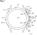
- this actuating device 19 comprises two lever elements 15c, 15d each capable of actuating a push button of the case 6 of the watch 3.
- the second end 16b of each lever element 15c, 15d is fixed/mounted so as to be movable in rotation to the crown of said case 4.
- these lever elements 15c, 15d are fixed so as to be movable to a part 20 of the caseband forming a protrusion extending radially relative to the center of the case 4 crossed by the central axis O.
- this protrusion 20 is defined on a lateral part of the case 4.
- These lever elements 15c, 15d are fixed so as to be movable preferably at two different attachment points 18 of this protrusion 20.
- this protrusion 20 may be a crown movable only in translation in a direction parallel to the central axis A of this outgrowth 20.
- This central axis A is under these conditions perpendicular or substantially perpendicular to the central axis O.
- Each lever element 15a, 15b, 15c, 15d is capable of alternating between a so-called “inactivation” state in which the lever element 15a, 15b, 15c, 15d is configured in a position in which it does not does not participate in actuating the push button of the watch case 6 and a so-called “activation” state in which the lever element 15a, 15b, 15c, 15d is configured in a position in which it participates in actuating this push button.
- the actuating device 19 also comprises at least one return element capable of returning the lever element 15a, 15b, 15c, 15d from an inactivation state to an activation state.
- the actuating device 19 may comprise in this configuration an element for limiting an angular displacement 13 of the lever element 15a, 15b, 15c, 15d relative to the housing 4 and therefore relative to the caseband 10c of this housing 4 when this lever element 15a, 15b, 15c, 15d is operated in a direction of movement opposite to that of the hands of a clock, also called “counterclockwise”, for example by the return element.
- the lever element 15a, 15b, 15c, 15d comprises an actuating zone 21 capable of activating the push button of the watch 3 by coming into contact with at least one activation zone 22 of the caseband 10c of the case 4. This activation is carried out as soon as this lever element 15a, 15b, 15c, 15d is operated in an angular displacement 13 relative to this activation zone 22 of the caseband 10c, this displacement 13 being carried out in the direction of movement of the hands of a watch otherwise called “clockwise”.
- Such an actuation zone 21 is defined on a portion of an external surface of the lever element 15a, 15b, 15c, 15d. This portion is arranged opposite a portion of the external face 23 of the middle 10c where the activation zone 22 is located. This portion may be between the attachment point 18 to the housing 4 of this lever element 15a, 15b, 15c, 15d and its free end included. As an example, this actuation zone 21 may be defined at this free end 16a.
- activation of the push button of the watch case 6 by the lever element 15a, 15b, 15c, 15d is indirect.
- the actuation zone 21 is capable of activating the push button of the watch 3 by coming into indirect contact with the latter, via the activation zone 22 of the caseband 10c.
- This activation zone 22 is included in the actuation device 19 and is configured to interact with the lever element 15a, 15b, 15c, 15d.
- Such an activation zone 22 may comprise a sliding member, in particular a push button arranged in the caseband 10c and which is capable of coming into direct contact with the push button of the watch 3 as soon as this button is activated by the actuation zone 21 of the lever element 15a, 15b, 15c, 15d.
- this activation zone 22 may be a portion of the caseband 10c which is capable of deforming in order to come into contact with the push button of the watch 3.
- the Dewar device 1 comprises two lever elements 15a, 15b, 15c, 15d provided to activate two separate push buttons of the case 6 of the watch 3. These two lever elements 15a, 15b, 15c, 15d are arranged near or in the vicinity of the corresponding push buttons of the case 6 with which they are intended to cooperate indirectly.
- the first and second push buttons are arranged on a caseband of the case 6 of the watch 3 respectively in the “2 o'clock” and “4 o'clock” areas.
- such an actuating device 19 makes it possible to improve the use of the Dewar device 1, in particular when the user of this device 1 is not very skilled in the part of his body which allows him to manipulate it. This lack of skill may result from a handicap or even the fact that this user wears thick gloves on his hands which prevent him from being precise with his fingers to manipulate this Dewar 1 device.
- a Dewar 1 device is particularly suitable for use by astronauts wearing their spacesuits or more generally by users/adventurers in spacesuits evolving in environments where extreme conditions prevail in terms of, for example, pressure, temperature, humidity, etc.
- the case 6 of the watch 3 is arranged in the enclosure 5 of the case 4 while being kept away or at a distance from all of the elements 10a to 10c of this case 4.
- This distance or this distance or even this spacing is configured from at least one fixing device 7 of the case 6 of the watch 3 included in the case 4.
- the fixing device 7 is configured to produce or maintain a spacing between said case 6 and all of the elements 10a, 10b, 10c of the case 4 forming said enclosure 5 of this case 4.
- This fixing device 7 helps to reduce or even eliminate any thermal conduction between the inner peripheral wall 12 of the caseband 10c and/or the back 10b and/or the crystal 10a with the case 6 of the watch 3 in particular with an external overall face of this case 6.
- This external overall face comprises an upper face comprising the crystal 11 of the case 6 of this watch 3, a lower face comprising a bottom of said case 6 and an external peripheral wall of a middle of this case 6. It is understood that the lower and upper faces are opposite each other.
- the fixing device 7 is arranged on an internal peripheral wall 12 of the enclosure of the case 4. In this configuration, the fixing device 7 mechanically connects, in particular reversibly, the case 6 of watch 3 to the internal peripheral wall 12 of the enclosure of the case 4.
- the Dewar device 1 may comprise two fixing devices 7 arranged in the enclosure while being opposite each other.
- a box 6 is included in a watch 3 which can be an electronic watch, for example a quartz watch, or even a mechanical watch.
- the mechanical and/or functional components 2 of the watch 3, mentioned above, comprise, in a non-limiting and non-exhaustive manner: mechanical elements of the movement such as a sprung balance, wheels, a striking mechanism, a dial, hands, rings, seals and/or electronic and/or electrical components 2.
- electronic and/or electrical components 2 comprise, for example, a display device, a processor, a memory, an energy storage component, a motor, an integrated circuit and an electronic oscillator, etc.
- this Dewar device 1 has the same properties and characteristics as a Dewar tube/vessel well known in the state of the art. As we have previously mentioned, the properties and characteristics of this Dewar device 1 contribute to giving it good thermal insulation with regard to temperatures, in particular extreme temperatures, which may prevail in the external environment in which such a device 1 may be located.
- the crystal 10a, the caseband 10c and the back 10b of this device 1 together define the enclosure 5 of this case 4 which is capable of receiving the case 6 of the watch 3.
- These three elements 10a to 10c of the case 4, namely the caseband 10c, the crystal 10a and the back 10b, can be separate elements which are joined together to construct this enclosure 5.
- the caseband 10c and the back 10b of the case 4 can together form a single-piece part, said single-piece part defining an opening opposite the back 10b which is capable of being closed by the crystal 10a and this, in a reversible and sealed manner.
- caseband 10c and the crystal 10a of the case4 of the watch 3 can together form a single-piece part, said single-piece part defining an opening opposite the ice 10a which is capable of being closed by the bottom 10b and this, also in a reversible and watertight manner.
- the case 10c or the bottom 10b can also be, like the glass 10a, transparent elements of the housing 4 of the Dewar device 1.
- the peripheral wall 12 of the case 10c and the inner face of the bottom 10b can be coated with a metallic or similar reflective coating, such as for example a layer of silver.
- case 10c or the back 10b are preferably made, in a non-limiting and non-exhaustive manner, of a metallic material or of thermosetting or thermoplastic polymer resins reinforced with carbon or glass fibers or even of ceramic materials.
- the device 1 may comprise an interferometric filter arranged on an overall external face of the case 4, namely on an external peripheral wall of the caseband 10c and/or the external faces of the crystal 10a and the back 10b of this watch case 6 3.
- This interferometric filter may be a grid or a trellis forming a coating on this overall external face of the case 4.
- This grid or trellis has a mesh whose dimensions are such that they only allow certain predetermined wavelengths of the electromagnetic spectrum to pass through, typically the wavelengths of the visible range.
- the enclosure 5 of the case 4 comprising the watch case 6 is under vacuum or quasi-vacuum.
- the space defined between this case 6 and the inner peripheral wall 12 of the caseband 10c, the back 10b and the crystal 10a is empty of material or quasi-empty. It will be noted that when this device 1 is used in an environment devoid of air or substantially devoid of air, its enclosure is also under vacuum or quasi-vacuum.
- Such a Dewar device 1 helps to provide the mechanical and/or functional components 2 of the watch 3 with very good thermal insulation from the external environment by reducing or even preventing heat loss by radiation from the components arranged in the watch case 6 for a long period.
- the temperature outside the device 1 reaches extreme values, typically of the order of -125 to +125 °C
- the temperature inside the enclosure 5 remains substantially equal to the temperature present in the watch case 6 3 when it is arranged in the case 4, typically of the order of 20 °C.
- the temperature present in the case 6 of the watch 3 is a temperature which does not hinder the proper functioning of the watch 3.
- This temperature is maintained for a duration which is 5 to 18 times greater than the duration during which such a watch case 3 would be capable of preserving an operating temperature of its components 2 by being located directly in such an environment where such temperatures prevail, in particular extreme ones (i.e. by being located outside the case of the Dewar device). It is thus understood that such a configuration makes it possible to protect the mechanical and/or functional components 2 of the watch 3, as well as to participate in ensuring their optimal functioning in extreme external temperature conditions.
Landscapes
- Physics & Mathematics (AREA)
- General Physics & Mathematics (AREA)
- Chemical & Material Sciences (AREA)
- Crystallography & Structural Chemistry (AREA)
- Electric Clocks (AREA)
Description
- La présente invention concerne un dispositif de Dewar pour des composants mécaniques et/ou fonctionnels d'une montre, le dispositif comprenant un dispositif d'actionnement d'au moins un bouton poussoir d'une montre agencée dans une enceinte de ce dispositif de Dewar.
- Une montre et en particulier une montre électronique comprend classiquement un bracelet et une boîte de montre comportant plusieurs composants électriques ou électroniques. Il est connu dans l'état de la technique que certains de ces composants ne supportent pas des températures extrêmes, et cessent de fonctionner correctement à ces températures. Typiquement, les écrans à cristaux liquides LCD (de l'anglais Liquid Crystal Display) utilisant des diodes électroluminescentes ou encore les quartz tolèrent des températures n'excédant pas 80 °C (degrés Celcius) environ, et ne descendant pas en-dessous de 0 °C. Or, dans des environnements particuliers tels que par exemple les missions spatiales ou lunaires, les températures peuvent fréquemment atteindre des valeurs de l'ordre de sensiblement -150 °C à +125 °C.
- On connait aussi dans l'état de la technique les documents
CH716913A2 2018/215491A1 qui portent sur des dispositifs de Dewar pour des composants d'une montre, le dispositif comprenant un bracelet, un boitier comportant une enceinte dans laquelle sont susceptibles d'être disposés ces composants et au moins un dispositif de fixation fixant lesdits composants dans ladite enceinte du boitier en les maintenant éloignés d'un ensemble d'éléments formant ladite enceinte. - Il existe donc un besoin de pouvoir utiliser une montre notamment une montre électronique dans des environnements où peuvent régner de telles températures extrêmes.
- L'invention concerne un dispositif de Dewar pour une montre, ledit dispositif comportant : un bracelet, un boitier comprenant une enceinte dans laquelle est susceptible d'être disposée une boite de la montre de manière à ce qu'une glace de ladite boite est agencée en regard d'une glace d'un ensemble d'éléments du boitier définissant cette enceinte, au moins un dispositif de fixation fixant ladite boite de montre dans ladite enceinte du boitier en la maintenant éloignée de l'ensemble des éléments du boitier définissant cette enceinte, et un dispositif d'actionnement d'au moins un bouton poussoir de la montre par le déplacement angulaire d'une extrémité libre d'au moins un élément de levier dudit dispositif relativement au boitier ledit au moins un élément de levier ayant une autre extrémité fixée mobile audit boitier.
- Dans d'autres modes de réalisation :
- ledit dispositif d'actionnement comprend ledit au moins un élément de levier qui est configuré pour actionner ledit au moins un bouton poussoir par déplacement angulaire de l'extrémité libre de ce dit au moins un élément de levier relativement au boitier, ledit au moins un élément de levier ayant son autre extrémité fixée mobile audit boitier ;
- ladite autre extrémité de ce dit au moins un élément de levier est fixé mobile à une corne d'une paire de cornes dudit boitier ;
- ladite autre extrémité dudit au moins un élément de levier est fixé mobile à une couronne dudit boitier ;
- ledit dispositif d'actionnement comprend au moins un élément de limitation d'un déplacement angulaire de l'extrémité libre lorsque ladite extrémité libre est opérée en sens inverse des aiguilles d'une montre ;
- ledit au moins un élément de levier comprend un corps monobloc ayant une forme essentiellement rectiligne ;
- ledit au moins un élément de levier comprend un élément de liaison susceptible d'assurer une fixation mobile de l'autre extrémité de cet élément de levier à une corne ou une couronne du boitier ;
- ledit au moins un élément de levier comprend une zone d'actionnement notamment définie sur ladite extrémité libre, ladite zone d'actionnement étant susceptible d'activer le bouton poussoir de la montre en entrant en contact avec au moins une zone d'activation de la carrure du boitier ;
- la zone d'activation comprend un organe coulissant, notamment un bouton poussoir, agencé dans la carrure susceptible d'entrer en contact avec le bouton poussoir de la montre dès lors que le bouton poussoir de cette zone d'activation est sollicité par ledit au moins un élément de levier ;
- le dispositif de Dewar comprend deux éléments de levier fixés mobiles chacune à une corne du boitier ou à une excroissance définie sur une partie latérale du boitier ;
- D'autres particularités et avantages ressortiront clairement de la description qui en est faite ci-après, à titre indicatif et nullement limitatif, en référence aux figures annexés suivantes :
- la
figure 1 est une vue en coupe d'une représentation schématique d'un dispositif de Dewar pour des composants mécaniques et/ou fonctionnels d'une montre pourvu d'un dispositif d'actionnement d'au moins un bouton poussoir d'une montre, selon un mode de réalisation de l'invention, et - les
figures 2 et3 sont des représentations schématiques fonctionnelles décrivant les différents modes opératoires relatifs à la mise en oeuvre du dispositif d'actionnement, selon le mode de réalisation de l'invention. - Sur la
figure 1 est représentée schématiquement un dispositif horloger isotherme 1 pour des composants mécaniques et/ou fonctionnels 2 d'une montre 3 aussi nommé « dispositif horloger de Dewar » ou « dispositif de protection » ou plus simplement dans la suite de la description « dispositif de Dewar ». Un tel dispositif de Dewar 1 est apte à participer à conférer notamment une bonne isolation thermique à des composants mécaniques et/ou fonctionnels 2 de la montre 3 dont la boite 6 est agencée dans le boitier 4 de ce dispositif 1. - Ce dispositif de Dewar 1 est notamment formé par la combinaison de son boitier 4 et de la boite 6 de montre 3 afin de réaliser une isolation thermique idoine pour ces composants mécaniques et/ou fonctionnels 2. Dans cette configuration, la boite 6 de montre 3 est agencée dans une enceinte 5 du boitier 4 en étant maintenue éloignée ou à distance de l'ensemble des éléments 10a à 10c du boitier 4 définissant cette dite enceinte 5 à savoir la glace 10a, une paroi périphérique intérieure 12 d'une carrure 10c et un fond 10b de ce boitier 4. On notera que cette paroi périphérique intérieure 12 est aussi celle de ladite enceinte 5.
- Dans ce contexte, ce dispositif 1 comprend donc le boitier 4 qui comporte la carrure 10c pourvue de préférence de deux paires de cornes 14 sur lesquelles est monté un bracelet permettant à un utilisateur de ce dispositif 1 de le porter par exemple au poignet. Ce boitier 4 comporte aussi une couronne, une glace 10a et un fond 10b visible sur les
figures 1 à 3 . Dans ce dispositif 1, on notera que la glace 10a comprend de préférence une surface qui est sensiblement supérieure ou strictement supérieure à une glace 11 de la boite 6 de montre 3. - Ce boitier 4 comprend également une lunette qui peut être montée mobile en rotation relativement à la carrure 10c. Une telle lunette a une forme essentiellement circulaire.
- Ce dispositif de Dewar 1 comprend aussi un dispositif d'actionnement 19 d'au moins un bouton poussoir de la boite 6 de la montre 3 agencée dans l'enceinte 5 de son boitier 4. Ce dispositif d'actionnement 19 comprend au moins un élément de levier 15a, 15b, 15c, 15d du boitier 4 qui est monté mobile sur ce boitier 4. Un tel élément de levier 15a, 15b, 15c, 15d est apte à réaliser un déplacement 13 relativement au boitier 4 afin d'actionner ledit bouton poussoir de la boite 6 de montre 3.
- Cet élément de levier 15a, 15b, 15c, 15d comprend un corps rigide monobloc ayant une forme essentiellement rectiligne. Cet élément de levier 15a, 15b, 15c, 15d comprend deux extrémités 16a, 16b. Une première extrémité 16a dite « extrémité libre » qui est apte à entrer en contact de manière indirecte avec le bouton poussoir de la boite 6 et une deuxième extrémité 16b dite « extrémité d'attache » qui est fixée/montée mobile en rotation autour d'un axe de fixation B sur le boitier 4 du dispositif de Dewar 1. Un tel axe de fixation B est défini au niveau du point d'attache 18 au boitier 4 de l'élément de levier 15a, 15b, 15c, 15d, cet axe de fixation B étant parallèle ou sensiblement parallèle à un axe central O du boitier 4 du dispositif de Dewar 1. On comprend que cette deuxième extrémité 16b est fixée mobile au niveau de ce point d'attache 18 à partir d'un élément de liaison 24.
- Dans ces conditions, on comprend que l'extrémité libre 16a de cet élément de levier 15a, 15b, 15c, 15d est alors apte à réaliser un déplacement angulaire 13 relativement à l'extrémité d'attache 16b lorsque l'élément de levier 15a, 15b, 15c, 15d est sollicité par l'utilisateur du dispositif de Dewar 1 dans le but d'activer le bouton poussoir de la boite 6 de la montre 3. Autrement dit, l'élément de levier 15a, 15b, 15c, 15d est configuré pour actionner ledit bouton poussoir lors d'une réalisation d'un déplacement angulaire 13 de la première extrémité 16a de ce dit au moins un élément de levier 15a, 15b, 15c, 15d relativement au boitier 4 et plus particulièrement relativement à une paroi périphérique extérieure 17 de ce boitier 4 et donc à une face externe 23 de sa carrure 10c.
- Sur la
figure 2 , ce dispositif d'actionnement 19 comprend deux éléments de levier 15a, 15b susceptibles d'actionner chacun un bouton poussoir de la boite 6 de la montre 3. Dans cette configuration, la deuxième extrémité 16b de chaque élément de levier 15a, 15b, est fixée/montée mobile en rotation à la corne de la paire de cornes 14 dudit boitier 4. Dans cette configuration, ces éléments de levier 15a, 15b sont fixés mobiles à des cornes de paires de cornes 14 différentes du boitier 4. - Sur la
figure 3 , ce dispositif d'actionnement 19 comprend deux éléments de levier 15c, 15d susceptibles d'actionner chacun un bouton poussoir de la boite 6 de la montre 3. Dans cette configuration, la deuxième extrémité 16b de chaque élément de levier 15c, 15d, est fixée/montée mobile en rotation à la couronne dudit boitier 4. Dans cette configuration, ces éléments de levier 15c, 15d sont fixés mobiles à une partie 20 de la carrure formant une excroissance s'étendant radialement par rapport au centre du boitier 4 traversé par à l'axe central O. Autrement dit, cette excroissance 20 est définie sur une partie latérale de la boitier 4. Ces éléments de levier 15c, 15d sont fixés mobiles de préférence au niveau de deux points d'attache 18 différents de cette excroissance 20. On notera que cette excroissance 20 peut être une couronne mobile uniquement en translation selon une direction parallèle à l'axe central A de cette excroissance 20. Cet axe central A est dans ces conditions perpendiculaire ou sensiblement perpendiculaire à l'axe central O. - Chaque élément de levier 15a, 15b, 15c, 15d est susceptible de d'alterner entre un état dit « d'inactivation » lors duquel l'élément de levier 15a, 15b, 15c, 15d est configuré dans une position dans laquelle il ne participe pas à actionner le bouton poussoir de la boite 6 de montre 3 et un état dit « d'activation » lors duquel l'élément de levier 15a, 15b, 15c, 15d est configuré dans une position dans laquelle il participe à actionner ce bouton poussoir.
- En outre, le dispositif d'actionnement 19 comprend aussi au moins un élément de rappel susceptible de rappeler l'élément de levier 15a, 15b, 15c, 15d d'un état d'inactivation à un état d'activation. On notera d'ailleurs que le dispositif d'actionnement 19 peut comprendre dans cette configuration un élément de limitation d'un déplacement angulaire 13 de l'élément de levier 15a, 15b, 15c, 15d par rapport au boitier 4 et donc par rapport à la carrure 10c de ce boitier 4 lorsque cet élément de levier 15a, 15b, 15c, 15d est opéré dans un sens de déplacement inverse à celui des aiguilles d'une montre, aussi appelé « sens antihoraire », par exemple par l'élément de rappel.
- Dans ce dispositif d'actionnement 19, l'élément de levier 15a, 15b, 15c, 15d comprend une zone d'actionnement 21 susceptible d'activer le bouton poussoir de la montre 3 en entrant en contact avec au moins une zone d'activation 22 de la carrure 10c du boitier 4. Cette activation est réalisée dès lors que cet élément de levier 15a, 15b, 15c, 15d est opéré dans un déplacement angulaire 13 relativement à cette zone d'activation 22 de la carrure 10c, ce déplacement 13 étant réalisé dans le sens de déplacement des aiguilles d'une montre autrement appelé « sens horaire ».
- Une telle zone d'actionnement 21 est définie sur une partie d'une surface externe de l'élément de levier 15a, 15b, 15c, 15d. Cette partie est agencée en regard d'une portion de la face externe 23 de la carrure 10c où est localisée la zone d'activation 22. Cette partie peut être comprise entre le point d'attache 18 au boitier 4 de cet élément de levier 15a, 15b, 15c, 15d et son extrémité libre inclue. A titre d'exemple, cette zone d'actionnement 21 peut être définie au niveau de cette extrémité libre 16a.
- Dans cette configuration, activation du bouton poussoir de la boite 6 de montre 3 par l'élément de levier 15a, 15b, 15c, 15d est indirecte. En effet, la zone d'actionnement 21 est susceptible d'activer le bouton poussoir de la montre 3 en entrant en contact de manière indirecte avec ce dernier et ce, par l'intermédiaire de la zone d'activation 22 de la carrure10c.
- Cette zone d'activation 22 est comprise dans le dispositif d'actionnement 19 et est configurée pour interagir avec l'élément de levier 15a, 15b, 15c, 15d. Une telle zone d'activation 22 peut comprendre un organe coulissant, notamment un bouton poussoir agencé dans la carrure 10c et qui est susceptible d'entrer en contact directement avec le bouton poussoir de la montre 3 dès lors que ce bouton est sollicité par la zone d'actionnement 21 de l'élément de levier 15a, 15b, 15c, 15d. Dans une alternative, cette zone d'activation 22 peut être une portion de la carrure 10c qui est susceptible de se déformer afin d'entrer en contact avec le bouton poussoir de la montre 3.
- En référence aux
figures 2 et3 , le dispositif de Dewar 1 comprend deux éléments de levier 15a, 15b, 15c, 15d prévus pour activer deux boutons poussoirs distincts de la boite 6 de la montre 3. Ces deux éléments de levier 15a, 15b, 15c, 15d sont agencés à proximité ou au voisinage des boutons poussoirs correspondant de la boite 6 avec lesquels ils sont destinés à coopérer de manière indirecte. A titre d'exemple, les premier et deuxième boutons poussoirs sont agencés sur une carrure de la boite 6 de montre 3 respectivement dans les zones des « 2 heures » et « 4 heures ». - En outre on comprend donc que dans ce dispositif d'actionnement 19 le bouton poussoir de la montre 3 est activé par l'élément de levier 15a, 15b, 15c, 15d, à partir du déplacement angulaire 13 de la zone d'actionnement 21 compris sur l'élément de levier 15a, 15b, 15c, 15d relativement à la zone d'activation 22 compris dans la carrure 10c du boitier 4.
- On comprend qu'un tel dispositif d'actionnement 19 permet d'améliorer l'utilisation du dispositif de Dewar 1 notamment lorsque l'utilisateur de ce dispositif 1 n'est pas très habile de la partie de son corps qui lui permet de le manipuler. Ce manque d'habilité peut résulter d'un handicap ou encore du fait que cet utilisateur porte des gants épais aux mains ce qui l'empêchent d'être précis avec ses doigts pour manipuler ce dispositif de Dewar 1. Dans ce contexte, on notera qu'un tel dispositif Dewar 1 est particulièrement adapté à une utilisation par des astronautes vêtus de leur combinaison spatiale ou plus généralement par des utilisateurs/aventuriers en combinaison évoluant dans des environnements où règnent des conditions extrêmes en termes par exemple de pression, température, humidité, etc...
- Ainsi que nous l'avons vu précédemment, la boite 6 de montre 3 est agencée dans l'enceinte 5 du boitier 4 en étant maintenue éloignée ou à distance de l'ensemble des éléments 10a à 10c de ce boitier 4. Cet éloignement ou cette distance ou encore cet écartement est configuré (e) à partir d'au moins un dispositif de fixation 7 de la boite 6 de montre 3 compris dans le boitier 4. Autrement dit, le dispositif de fixation 7 est configuré pour réaliser ou maintenir un écartement entre ladite boite 6 et l'ensemble des éléments 10a, 10b, 10c du boitier 4 formant ladite enceinte 5 de ce boitier 4. Ce dispositif de fixation 7 participe à réduire voire à supprimer toute conduction thermique entre la paroi périphérique intérieure 12 de la carrure 10c et/ou le fond 10b et/ou la glace 10a avec la boite 6 de montre 3 en particulier avec une face globale externe de cette boite 6. Cette face globale externe comporte une face supérieure comprenant la glace 11 de la boite 6 de cette montre 3, une face inférieure comprenant un fond de ladite boite 6 et une paroi périphérique externe d'une carrure de cette boite 6. On comprend que les faces inférieure et supérieure sont opposées l'une à l'autre. On notera que le dispositif de fixation 7 est agencé sur une paroi périphérique intérieure 12 de l'enceinte du boitier 4. Dans cette configuration le dispositif de fixation 7 relie mécaniquement, notamment de manière réversible, la boite 6 de montre 3 à la paroi périphérique intérieure 12 de l'enceinte du boitier 4. En outre, le dispositif de Dewar 1 peut comprendre deux dispositifs de fixation 7 agencés dans l'enceinte en étant opposés l'un à l'autre.
- On notera qu'une telle boite 6 est comprise dans une montre 3 qui peut être une montre électronique par exemple une montre à quartz, ou encore une montre mécanique.
- Les composants mécaniques et/ou fonctionnels 2 de la montre 3, évoqués précédemment, comprennent de manière non limitative et non exhaustive : des éléments mécaniques du mouvement tels qu'un balancier-spiral, des roues, un mécanisme de sonnerie, un cadran, des aiguilles, des bagues, des joints et/ou des composants électroniques et/ou électriques 2. On remarquera en particulier que de tels composants électroniques et/ou électriques 2 comportent par exemple un dispositif d'affichage, un processeur, une mémoire, un composant de stockage d'énergie, un moteur, un circuit intégré et un oscillateur électronique, etc...
- On comprend donc que dans cette configuration, ce dispositif de Dewar 1 présente les mêmes propriétés et caractéristiques qu'un tube/vase de Dewar bien connu dans l'état de la technique. Ainsi que nous l'avons précédemment évoqué, les propriétés et caractéristiques de ce dispositif de Dewar 1 participent à lui conférer une bonne isolation thermique au regard de températures notamment extrêmes pouvant régner dans l'environnement extérieur dans lequel un tel dispositif 1 peut être localisé.
- Ainsi que nous l'avons vu, la glace 10a, la carrure 10c et le fond 10b de ce dispositif 1 définissent ensemble l'enceinte 5 de ce boitier 4 qui est susceptible de recevoir la boite 6 de montre 3. Ces trois éléments 10a à 10c du boitier 4 à savoir la carrure 10c, la glace 10a et le fond 10b peuvent être des éléments distincts qui sont joints ensemble pour construire cette enceinte 5. De manière alternative, la carrure 10c et le fond 10b du boitier 4 peuvent former ensemble une pièce monobloc, ladite pièce monobloc définissant une ouverture opposée au fond 10b qui est susceptible d'être refermée par la glace 10a et ce, de manière réversible et étanche. Dans une alternative, la carrure 10c et la glace 10a du boitier4 de montre 3, peuvent former ensemble une pièce monobloc, ladite pièce monobloc définissant une ouverture opposée à la glace 10a qui est susceptible d'être refermée par le fond 10b et ce, aussi de manière réversible et étanche.
- La carrure 10c ou le fond 10b peuvent être également comme la glace 10a, éléments transparents du boitier 4 du dispositif de Dewar 1. Dans une telle configuration, la paroi périphérique 12 de la carrure 10c et la face intérieure du fond 10b peuvent être revêtues d'un enduit réfléchissant métallique ou similaire, tel que par exemple d'une couche d'argent.
- On notera cependant que la carrure 10c ou le fond 10b sont de préférence réalisés de manière non limitative et non exhaustive en une matière métallique ou en des résines polymères thermodurcissables ou thermoplastiques renforcées de fibres de carbone ou de verre ou encore en matériaux céramiques.
- En complément, le dispositif 1 peut comprendre un filtre interférométrique agencé sur une face globale externe du boitier 4 à savoir sur une paroi périphérique extérieure de la carrure 10c et/ou des faces extérieures de la glace 10a et du fond 10b de cette boite 6 de montre 3. Ce filtre interférométrique peut être un grillage ou un treillis formant un revêtement sur cette face globale externe du boitier 4. Ce grillage ou treillis présente un maillage dont les dimensions sont telles qu'elles ne laissent passer que certaines longueurs d'onde prédéterminées du spectre électromagnétique, typiquement les longueurs d'onde du domaine visible.
- En outre lorsque le dispositif 1 est prévu pour être utilisé dans un environnement comprenant de l'air, l'enceinte 5 du boitier 4 comprenant la boite 6 de montre, est sous vide ou quasi sous vide. Autrement dit, dans cette enceinte, l'espace défini entre cette boite 6 et la paroi périphérique intérieure 12 de la carrure 10c, le fond 10b et la glace 10a est vide de matière ou quasi vide. On notera que lorsque ce dispositif 1 est utilisé dans un environnement dépourvu d'air ou sensiblement dépourvu, son enceinte est aussi sous vide ou quasi sous vide.
- Un tel dispositif de Dewar 1 dont l'utilisation ou la manipulation est facilitée grâce au dispositif d'actionnement, participe à fournir aux composants mécaniques et/ou fonctionnels 2 de la montre 3 une très bonne isolation thermique vis-à-vis de l'environnement extérieur en réduisant voire en empêchant une déperdition thermique par radiation des composants agencés dans la boite 6 de montre pendant une longue durée. Ainsi, lorsque la température à l'extérieur du dispositif 1 atteint des valeurs extrêmes, typiquement de l'ordre de -125 à +125 °C, la température à l'intérieur de l'enceinte 5 reste quant à elle sensiblement égale à la température présente dans la boite 6 de montre 3 lors de son agencement dans le boitier 4, typiquement de l'ordre de 20 °C. On notera que quelles que soient les conditions de température régnant dans l'environnement du dispositif de Dewar 1, la température présente dans la boite 6 de montre 3 est une température qui n'entrave pas le bon fonctionnement de la montre 3. Cette température est maintenue sur une durée qui est 5 à 18 fois plus importante que la durée pendant laquelle une telle boite de montre 3 serait capable de préserver une température de fonctionnement de ses composants 2 en étant située directement dans un tel environnement où règnent de telles températures notamment extrêmes (c'est-à-dire en étant située hors du boitier du dispositif de Dewar). On conçoit ainsi qu'une telle configuration permet de protéger les composants mécaniques et/ou fonctionnels 2 de la montre 3, ainsi que de participer à assurer leur fonctionnement de manière optimale dans des conditions de température extérieure extrêmes.
Claims (10)
- Dispositif de Dewar (1) pour une montre (3), ledit dispositif (1) comportant :- un bracelet ;- un boitier (4) comprenant une enceinte (5) dans laquelle est susceptible d'être disposée une boite (6) de la montre (3) de manière à ce qu'une glace de ladite boite (6) est agencée en regard d'une glace (10a) d'un ensemble d'éléments (10a, 10b, 10c) du boitier (4) définissant cette enceinte (5) ;- au moins un dispositif de fixation (7) fixant ladite boite (6) de montre (3) dans ladite enceinte (5) du boitier (4) en la maintenant éloignée de l'ensemble des éléments (10a, 10b, 10c) du boitier (4) définissant cette enceinte (5), et- un dispositif d'actionnement (19) d'au moins un bouton poussoir de ladite montre par le déplacement angulaire (13) d'une extrémité libre (16a) d'au moins un élément de levier (15a, 15b, 15c, 15d) dudit dispositif (19) relativement au boitier (4 ) ledit au moins un élément de levier (15a, 15b, 15c, 15d) ayant une autre extrémité (16b) fixée mobile audit boitier (4).
- Dispositif de Dewar (1) selon la revendication précédente, caractérisé en ce que ledit dispositif d'actionnement (19) comprend ledit au moins un élément de levier (15a, 15b, 15c, 15d) qui est configuré pour actionner ledit au moins un bouton poussoir par déplacement angulaire (13) de l'extrémité libre (16a) de ce dit au moins un élément de levier (15a, 15b, 15c, 15d) relativement au boitier (4), ledit au moins un élément de levier (15a, 15b, 15c, 15d) ayant son autre extrémité (16b) fixée mobile audit boitier (4).
- Dispositif de Dewar (1) selon l'une quelconque des revendications précédentes, caractérisé en ce que ladite autre extrémité (16b) de ce dit au moins un élément de levier (15a, 15b) est fixé mobile à une corne d'une paire de cornes (14) dudit boitier (4).
- Dispositif de Dewar (1) selon l'une quelconque des revendications 1 et 2, caractérisé en ce que ladite autre extrémité (16b) dudit au moins un élément de levier (15c, 15d) est fixé mobile à une couronne (20) dudit boitier (4).
- Dispositif de Dewar (1) selon l'une quelconque des revendications précédentes, caractérisé en ce que ledit dispositif d'actionnement (19) comprend au moins un élément de limitation d'un déplacement angulaire (13) de l'extrémité libre (16a) lorsque ladite extrémité libre (16a) est opérée en sens inverse des aiguilles d'une montre.
- Dispositif de Dewar (1) selon l'une quelconque des revendications précédentes, caractérisé en ce que ledit au moins un élément de levier (15a, 15b, 15c, 15d) comprend un corps monobloc ayant une forme essentiellement rectiligne.
- Dispositif de Dewar (1) selon l'une quelconque des précédentes, caractérisé en ce que ledit au moins un élément de levier (15a, 15b, 15c, 15d) comprend un élément de liaison (24) susceptible d'assurer une fixation mobile de l'autre extrémité (16b) de cet élément de levier (15a, 15b, 15c, 15d) à une corne ou une couronne (20) du boitier (4).
- Dispositif de Dewar (1) selon l'une quelconque des revendications précédentes, caractérisé en ce que ledit au moins un élément de levier (15a, 15b, 15c, 15d) comprend une zone d'actionnement (21) notamment définie sur ladite extrémité libre (16a), ladite zone d'actionnement (21) étant susceptible d'activer le bouton poussoir de la montre (3) en entrant en contact avec au moins une zone d'activation (22) de la carrure (10c) du boitier (4).
- Dispositif de Dewar (1) selon la revendication précédente, caractérisé en ce que la zone d'activation (22) comprend un organe coulissant, notamment un bouton poussoir, agencé dans la carrure (10c) susceptible d'entrer en contact avec le bouton poussoir de la montre dès lors que le bouton poussoir de cette zone d'activation (22) est sollicité par ledit au moins un élément de levier (15a, 15b, 15c, 15d).
- Dispositif de Dewar (1) selon l'une quelconque des revendications précédentes, caractérisé en ce qu'il comprend deux éléments de levier (15a, 15b, 15c, 15d) fixés mobiles chacune à une corne du boitier (4) ou à une à une excroissance (20) définie sur une partie latérale du boitier (4).
Priority Applications (5)
| Application Number | Priority Date | Filing Date | Title |
|---|---|---|---|
| EP21180254.1A EP4105736B1 (fr) | 2021-06-18 | 2021-06-18 | Dispositif de dewar pour montre comprenant un dispositif d'actionnement |
| US17/658,147 US11947318B2 (en) | 2021-06-18 | 2022-04-06 | Dewar device comprising an actuation device |
| JP2022078083A JP7320647B2 (ja) | 2021-06-18 | 2022-05-11 | 作動デバイスを備えるデュワーデバイス |
| KR1020220059600A KR102897539B1 (ko) | 2021-06-18 | 2022-05-16 | 작동 디바이스를 포함하는 듀어 디바이스 |
| CN202210619413.2A CN115494719A (zh) | 2021-06-18 | 2022-05-25 | 包括致动装置的杜瓦装置 |
Applications Claiming Priority (1)
| Application Number | Priority Date | Filing Date | Title |
|---|---|---|---|
| EP21180254.1A EP4105736B1 (fr) | 2021-06-18 | 2021-06-18 | Dispositif de dewar pour montre comprenant un dispositif d'actionnement |
Publications (2)
| Publication Number | Publication Date |
|---|---|
| EP4105736A1 EP4105736A1 (fr) | 2022-12-21 |
| EP4105736B1 true EP4105736B1 (fr) | 2025-02-19 |
Family
ID=76522888
Family Applications (1)
| Application Number | Title | Priority Date | Filing Date |
|---|---|---|---|
| EP21180254.1A Active EP4105736B1 (fr) | 2021-06-18 | 2021-06-18 | Dispositif de dewar pour montre comprenant un dispositif d'actionnement |
Country Status (5)
| Country | Link |
|---|---|
| US (1) | US11947318B2 (fr) |
| EP (1) | EP4105736B1 (fr) |
| JP (1) | JP7320647B2 (fr) |
| KR (1) | KR102897539B1 (fr) |
| CN (1) | CN115494719A (fr) |
Families Citing this family (1)
| Publication number | Priority date | Publication date | Assignee | Title |
|---|---|---|---|---|
| EP4390570A1 (fr) * | 2022-12-23 | 2024-06-26 | Omega SA | Systeme de dewar pour montres, comportant un système de reglage du contraste pour un dispositif d'affichage |
Citations (1)
| Publication number | Priority date | Publication date | Assignee | Title |
|---|---|---|---|---|
| US7001064B2 (en) * | 2000-05-18 | 2006-02-21 | Finazzi Pierre-Andre | Push-piece control device for a watch |
Family Cites Families (15)
| Publication number | Priority date | Publication date | Assignee | Title |
|---|---|---|---|---|
| US3030763A (en) * | 1959-06-23 | 1962-04-24 | Hans U Klingenberg | Waterproof watch casing |
| CH532917A (fr) * | 1970-07-13 | 1973-01-31 | Omega Brandt & Freres Sa Louis | Ensemble d'une montre et d'un boîtier protecteur |
| CH556561A (fr) * | 1971-02-19 | 1974-11-29 | ||
| CH537170A (fr) * | 1971-06-21 | 1973-05-31 | Omega Louis Brandt & Freres S | Boîtier de protection pour montre-bracelet |
| JPH0428076Y2 (fr) * | 1985-11-18 | 1992-07-07 | ||
| US4862521A (en) * | 1987-12-09 | 1989-09-05 | Mann Kevin D | Watch supporting, protecting and insulating device |
| CH698846B1 (fr) * | 2006-03-28 | 2009-11-13 | Meco Sa | Dispositif de commande d'une fonction horlogère ou non liée au temps et pièce d'horlogerie comprenant un tel dispositif. |
| JP2009229167A (ja) * | 2008-03-21 | 2009-10-08 | Seiko Epson Corp | 携帯時計 |
| EP2639656B1 (fr) * | 2012-03-13 | 2020-01-01 | Graham S.A. | Dispositif de commande pour montre de plongée |
| JP2016114407A (ja) * | 2014-12-12 | 2016-06-23 | セイコーエプソン株式会社 | 時計 |
| CN205176489U (zh) * | 2015-11-27 | 2016-04-20 | 东莞晶石光学有限公司 | 一种具有立体印刷感的手表玻璃 |
| EP3282323B1 (fr) * | 2016-08-12 | 2023-07-19 | Omega SA | Piece d'horlogerie avec poussoir escamotable |
| WO2018215491A1 (fr) * | 2017-05-22 | 2018-11-29 | Timelink Ag | Support de mouvement pour un mouvement de montre |
| EP3835891A1 (fr) * | 2019-12-09 | 2021-06-16 | Omega SA | Montre comprenant un element de filtrage optique |
| CH716913A2 (fr) * | 2019-12-09 | 2021-06-15 | Omega Sa | Montre électronique comprenant un dispositif de dewar. |
-
2021
- 2021-06-18 EP EP21180254.1A patent/EP4105736B1/fr active Active
-
2022
- 2022-04-06 US US17/658,147 patent/US11947318B2/en active Active
- 2022-05-11 JP JP2022078083A patent/JP7320647B2/ja active Active
- 2022-05-16 KR KR1020220059600A patent/KR102897539B1/ko active Active
- 2022-05-25 CN CN202210619413.2A patent/CN115494719A/zh active Pending
Patent Citations (1)
| Publication number | Priority date | Publication date | Assignee | Title |
|---|---|---|---|---|
| US7001064B2 (en) * | 2000-05-18 | 2006-02-21 | Finazzi Pierre-Andre | Push-piece control device for a watch |
Also Published As
| Publication number | Publication date |
|---|---|
| US11947318B2 (en) | 2024-04-02 |
| CN115494719A (zh) | 2022-12-20 |
| JP7320647B2 (ja) | 2023-08-03 |
| JP2023001033A (ja) | 2023-01-04 |
| KR102897539B1 (ko) | 2025-12-08 |
| EP4105736A1 (fr) | 2022-12-21 |
| US20220404775A1 (en) | 2022-12-22 |
| KR20220169393A (ko) | 2022-12-27 |
Similar Documents
| Publication | Publication Date | Title |
|---|---|---|
| EP4012510B1 (fr) | Dispositif horloger isotherme | |
| EP4012512B1 (fr) | Boitier d'un dispositif de dewar comprenant un élément de liaison d'une boite de montre | |
| EP3220210B1 (fr) | Piece d'horlogerie a sonnerie ou a musique, a lunette résonante | |
| CH701421A2 (fr) | Oscillateur mécanique. | |
| EP4105737B1 (fr) | Dispositif de dewar pour montre comprenant un dispositif d'actionnement | |
| EP4073597B1 (fr) | Montre comprenant un element de filtrage optique et un dispositif de dewar | |
| EP4105735B1 (fr) | Element d'habillage actionnable | |
| CH716913A2 (fr) | Montre électronique comprenant un dispositif de dewar. | |
| EP4105736A1 (fr) | Dispositif de dewar pour montre comprenant un dispositif d'actionnement | |
| CH718146A2 (fr) | Dispositif de Dewar pour des composants d'une montre. | |
| CH718752A2 (fr) | Dispositif de Dewar pour des composants d'une montre et comprenant un dispositif d'actionnement. | |
| EP0168010A1 (fr) | Boîte de montre | |
| CH716914A2 (fr) | Montre comprenant un élément de filtrage optique. | |
| CH718753A2 (fr) | Dispositif de Dewar pour des composants d'une montre et comprenant une lunette pivotante. | |
| CH718754A2 (fr) | Dispositif de Dewar comprenant un élément d'habillage actionnable. | |
| CH718145A2 (fr) | Dispositif de Dewar pour des composants mécaniques d'une montre. | |
| EP4012509B1 (fr) | Dispositif de dewar pour des composants mécaniques et/ou fonctionnels d'une montre | |
| EP0628895A1 (fr) | Montre avec verre ou ensemble verre-lunette rotatif étanche | |
| CH718144A2 (fr) | Dispositif horloger isotherme. | |
| EP4120029B1 (fr) | Dispositif de dewar comprenant un élément d'habillage transparent | |
| CH700657B1 (fr) | Montre mystérieuse. | |
| CH720386A2 (fr) | Dispositif isotherme comprenant un système d'affichage d'informations | |
| CH709421B1 (fr) | Boîte pour pièce d'horlogerie avec blindage magnétique comportant un diaphragme. | |
| EP3835884A1 (fr) | Montre electronique comprenant un dispositif de dewar | |
| CH720384A2 (fr) | Dispositif isotherme pour montre |
Legal Events
| Date | Code | Title | Description |
|---|---|---|---|
| PUAI | Public reference made under article 153(3) epc to a published international application that has entered the european phase |
Free format text: ORIGINAL CODE: 0009012 |
|
| STAA | Information on the status of an ep patent application or granted ep patent |
Free format text: STATUS: THE APPLICATION HAS BEEN PUBLISHED |
|
| AK | Designated contracting states |
Kind code of ref document: A1 Designated state(s): AL AT BE BG CH CY CZ DE DK EE ES FI FR GB GR HR HU IE IS IT LI LT LU LV MC MK MT NL NO PL PT RO RS SE SI SK SM TR |
|
| STAA | Information on the status of an ep patent application or granted ep patent |
Free format text: STATUS: REQUEST FOR EXAMINATION WAS MADE |
|
| 17P | Request for examination filed |
Effective date: 20230621 |
|
| RBV | Designated contracting states (corrected) |
Designated state(s): AL AT BE BG CH CY CZ DE DK EE ES FI FR GB GR HR HU IE IS IT LI LT LU LV MC MK MT NL NO PL PT RO RS SE SI SK SM TR |
|
| P01 | Opt-out of the competence of the unified patent court (upc) registered |
Effective date: 20230701 |
|
| GRAP | Despatch of communication of intention to grant a patent |
Free format text: ORIGINAL CODE: EPIDOSNIGR1 |
|
| STAA | Information on the status of an ep patent application or granted ep patent |
Free format text: STATUS: GRANT OF PATENT IS INTENDED |
|
| INTG | Intention to grant announced |
Effective date: 20241025 |
|
| GRAS | Grant fee paid |
Free format text: ORIGINAL CODE: EPIDOSNIGR3 |
|
| GRAA | (expected) grant |
Free format text: ORIGINAL CODE: 0009210 |
|
| STAA | Information on the status of an ep patent application or granted ep patent |
Free format text: STATUS: THE PATENT HAS BEEN GRANTED |
|
| AK | Designated contracting states |
Kind code of ref document: B1 Designated state(s): AL AT BE BG CH CY CZ DE DK EE ES FI FR GB GR HR HU IE IS IT LI LT LU LV MC MK MT NL NO PL PT RO RS SE SI SK SM TR |
|
| REG | Reference to a national code |
Ref country code: GB Ref legal event code: FG4D Free format text: NOT ENGLISH |
|
| REG | Reference to a national code |
Ref country code: CH Ref legal event code: EP |
|
| REG | Reference to a national code |
Ref country code: IE Ref legal event code: FG4D Free format text: LANGUAGE OF EP DOCUMENT: FRENCH |
|
| REG | Reference to a national code |
Ref country code: DE Ref legal event code: R096 Ref document number: 602021026258 Country of ref document: DE |
|
| REG | Reference to a national code |
Ref country code: NL Ref legal event code: MP Effective date: 20250219 |
|
| PG25 | Lapsed in a contracting state [announced via postgrant information from national office to epo] |
Ref country code: RS Free format text: LAPSE BECAUSE OF FAILURE TO SUBMIT A TRANSLATION OF THE DESCRIPTION OR TO PAY THE FEE WITHIN THE PRESCRIBED TIME-LIMIT Effective date: 20250519 |
|
| PG25 | Lapsed in a contracting state [announced via postgrant information from national office to epo] |
Ref country code: FI Free format text: LAPSE BECAUSE OF FAILURE TO SUBMIT A TRANSLATION OF THE DESCRIPTION OR TO PAY THE FEE WITHIN THE PRESCRIBED TIME-LIMIT Effective date: 20250219 |
|
| PG25 | Lapsed in a contracting state [announced via postgrant information from national office to epo] |
Ref country code: PL Free format text: LAPSE BECAUSE OF FAILURE TO SUBMIT A TRANSLATION OF THE DESCRIPTION OR TO PAY THE FEE WITHIN THE PRESCRIBED TIME-LIMIT Effective date: 20250219 |
|
| PGFP | Annual fee paid to national office [announced via postgrant information from national office to epo] |
Ref country code: DE Payment date: 20250520 Year of fee payment: 5 |
|
| PG25 | Lapsed in a contracting state [announced via postgrant information from national office to epo] |
Ref country code: ES Free format text: LAPSE BECAUSE OF FAILURE TO SUBMIT A TRANSLATION OF THE DESCRIPTION OR TO PAY THE FEE WITHIN THE PRESCRIBED TIME-LIMIT Effective date: 20250219 |
|
| REG | Reference to a national code |
Ref country code: LT Ref legal event code: MG9D |
|
| PG25 | Lapsed in a contracting state [announced via postgrant information from national office to epo] |
Ref country code: NO Free format text: LAPSE BECAUSE OF FAILURE TO SUBMIT A TRANSLATION OF THE DESCRIPTION OR TO PAY THE FEE WITHIN THE PRESCRIBED TIME-LIMIT Effective date: 20250519 Ref country code: IS Free format text: LAPSE BECAUSE OF FAILURE TO SUBMIT A TRANSLATION OF THE DESCRIPTION OR TO PAY THE FEE WITHIN THE PRESCRIBED TIME-LIMIT Effective date: 20250619 |
|
| PG25 | Lapsed in a contracting state [announced via postgrant information from national office to epo] |
Ref country code: NL Free format text: LAPSE BECAUSE OF FAILURE TO SUBMIT A TRANSLATION OF THE DESCRIPTION OR TO PAY THE FEE WITHIN THE PRESCRIBED TIME-LIMIT Effective date: 20250219 |
|
| PG25 | Lapsed in a contracting state [announced via postgrant information from national office to epo] |
Ref country code: HR Free format text: LAPSE BECAUSE OF FAILURE TO SUBMIT A TRANSLATION OF THE DESCRIPTION OR TO PAY THE FEE WITHIN THE PRESCRIBED TIME-LIMIT Effective date: 20250219 |
|
| PG25 | Lapsed in a contracting state [announced via postgrant information from national office to epo] |
Ref country code: LV Free format text: LAPSE BECAUSE OF FAILURE TO SUBMIT A TRANSLATION OF THE DESCRIPTION OR TO PAY THE FEE WITHIN THE PRESCRIBED TIME-LIMIT Effective date: 20250219 Ref country code: PT Free format text: LAPSE BECAUSE OF FAILURE TO SUBMIT A TRANSLATION OF THE DESCRIPTION OR TO PAY THE FEE WITHIN THE PRESCRIBED TIME-LIMIT Effective date: 20250620 |
|
| PGFP | Annual fee paid to national office [announced via postgrant information from national office to epo] |
Ref country code: FR Payment date: 20250520 Year of fee payment: 5 |
|
| PG25 | Lapsed in a contracting state [announced via postgrant information from national office to epo] |
Ref country code: GR Free format text: LAPSE BECAUSE OF FAILURE TO SUBMIT A TRANSLATION OF THE DESCRIPTION OR TO PAY THE FEE WITHIN THE PRESCRIBED TIME-LIMIT Effective date: 20250520 Ref country code: BG Free format text: LAPSE BECAUSE OF FAILURE TO SUBMIT A TRANSLATION OF THE DESCRIPTION OR TO PAY THE FEE WITHIN THE PRESCRIBED TIME-LIMIT Effective date: 20250219 |
|
| REG | Reference to a national code |
Ref country code: AT Ref legal event code: MK05 Ref document number: 1768862 Country of ref document: AT Kind code of ref document: T Effective date: 20250219 |
|
| PG25 | Lapsed in a contracting state [announced via postgrant information from national office to epo] |
Ref country code: SE Free format text: LAPSE BECAUSE OF FAILURE TO SUBMIT A TRANSLATION OF THE DESCRIPTION OR TO PAY THE FEE WITHIN THE PRESCRIBED TIME-LIMIT Effective date: 20250219 |
|
| PG25 | Lapsed in a contracting state [announced via postgrant information from national office to epo] |
Ref country code: SM Free format text: LAPSE BECAUSE OF FAILURE TO SUBMIT A TRANSLATION OF THE DESCRIPTION OR TO PAY THE FEE WITHIN THE PRESCRIBED TIME-LIMIT Effective date: 20250219 |
|
| PG25 | Lapsed in a contracting state [announced via postgrant information from national office to epo] |
Ref country code: DK Free format text: LAPSE BECAUSE OF FAILURE TO SUBMIT A TRANSLATION OF THE DESCRIPTION OR TO PAY THE FEE WITHIN THE PRESCRIBED TIME-LIMIT Effective date: 20250219 |
|
| PG25 | Lapsed in a contracting state [announced via postgrant information from national office to epo] |
Ref country code: IT Free format text: LAPSE BECAUSE OF FAILURE TO SUBMIT A TRANSLATION OF THE DESCRIPTION OR TO PAY THE FEE WITHIN THE PRESCRIBED TIME-LIMIT Effective date: 20250219 |
|
| PG25 | Lapsed in a contracting state [announced via postgrant information from national office to epo] |
Ref country code: AT Free format text: LAPSE BECAUSE OF FAILURE TO SUBMIT A TRANSLATION OF THE DESCRIPTION OR TO PAY THE FEE WITHIN THE PRESCRIBED TIME-LIMIT Effective date: 20250219 |
|
| PGFP | Annual fee paid to national office [announced via postgrant information from national office to epo] |
Ref country code: CH Payment date: 20250701 Year of fee payment: 5 |
|
| PG25 | Lapsed in a contracting state [announced via postgrant information from national office to epo] |
Ref country code: CZ Free format text: LAPSE BECAUSE OF FAILURE TO SUBMIT A TRANSLATION OF THE DESCRIPTION OR TO PAY THE FEE WITHIN THE PRESCRIBED TIME-LIMIT Effective date: 20250219 Ref country code: EE Free format text: LAPSE BECAUSE OF FAILURE TO SUBMIT A TRANSLATION OF THE DESCRIPTION OR TO PAY THE FEE WITHIN THE PRESCRIBED TIME-LIMIT Effective date: 20250219 |
|
| PG25 | Lapsed in a contracting state [announced via postgrant information from national office to epo] |
Ref country code: RO Free format text: LAPSE BECAUSE OF FAILURE TO SUBMIT A TRANSLATION OF THE DESCRIPTION OR TO PAY THE FEE WITHIN THE PRESCRIBED TIME-LIMIT Effective date: 20250219 |
|
| PG25 | Lapsed in a contracting state [announced via postgrant information from national office to epo] |
Ref country code: SK Free format text: LAPSE BECAUSE OF FAILURE TO SUBMIT A TRANSLATION OF THE DESCRIPTION OR TO PAY THE FEE WITHIN THE PRESCRIBED TIME-LIMIT Effective date: 20250219 |
|
| REG | Reference to a national code |
Ref country code: DE Ref legal event code: R097 Ref document number: 602021026258 Country of ref document: DE |
|
| PLBE | No opposition filed within time limit |
Free format text: ORIGINAL CODE: 0009261 |
|
| STAA | Information on the status of an ep patent application or granted ep patent |
Free format text: STATUS: NO OPPOSITION FILED WITHIN TIME LIMIT |
|
| 26N | No opposition filed |
Effective date: 20251120 |
|
| PG25 | Lapsed in a contracting state [announced via postgrant information from national office to epo] |
Ref country code: MC Free format text: LAPSE BECAUSE OF FAILURE TO SUBMIT A TRANSLATION OF THE DESCRIPTION OR TO PAY THE FEE WITHIN THE PRESCRIBED TIME-LIMIT Effective date: 20250219 |
|
| PG25 | Lapsed in a contracting state [announced via postgrant information from national office to epo] |
Ref country code: LU Free format text: LAPSE BECAUSE OF NON-PAYMENT OF DUE FEES Effective date: 20250618 |
|
| GBPC | Gb: european patent ceased through non-payment of renewal fee |
Effective date: 20250618 |
|
| REG | Reference to a national code |
Ref country code: BE Ref legal event code: MM Effective date: 20250630 |
|
| PG25 | Lapsed in a contracting state [announced via postgrant information from national office to epo] |
Ref country code: GB Free format text: LAPSE BECAUSE OF NON-PAYMENT OF DUE FEES Effective date: 20250618 |
|
| PG25 | Lapsed in a contracting state [announced via postgrant information from national office to epo] |
Ref country code: IE Free format text: LAPSE BECAUSE OF NON-PAYMENT OF DUE FEES Effective date: 20250618 |
|
| PG25 | Lapsed in a contracting state [announced via postgrant information from national office to epo] |
Ref country code: BE Free format text: LAPSE BECAUSE OF NON-PAYMENT OF DUE FEES Effective date: 20250630 |