EP4105732A1 - Calendar mechanism with display of the seasons for a timepiece - Google Patents
Calendar mechanism with display of the seasons for a timepiece Download PDFInfo
- Publication number
- EP4105732A1 EP4105732A1 EP21179694.1A EP21179694A EP4105732A1 EP 4105732 A1 EP4105732 A1 EP 4105732A1 EP 21179694 A EP21179694 A EP 21179694A EP 4105732 A1 EP4105732 A1 EP 4105732A1
- Authority
- EP
- European Patent Office
- Prior art keywords
- wheel
- drive
- date
- calendar mechanism
- month
- Prior art date
- Legal status (The legal status is an assumption and is not a legal conclusion. Google has not performed a legal analysis and makes no representation as to the accuracy of the status listed.)
- Withdrawn
Links
- 230000007246 mechanism Effects 0.000 title claims abstract description 40
- 230000000694 effects Effects 0.000 claims description 4
- 230000009471 action Effects 0.000 description 8
- 238000004804 winding Methods 0.000 description 6
- 210000003323 beak Anatomy 0.000 description 4
- 230000035939 shock Effects 0.000 description 3
- 230000008901 benefit Effects 0.000 description 2
- 230000005540 biological transmission Effects 0.000 description 2
- 230000001419 dependent effect Effects 0.000 description 2
- 238000006073 displacement reaction Methods 0.000 description 2
- 238000005265 energy consumption Methods 0.000 description 2
- 230000001932 seasonal effect Effects 0.000 description 2
- 230000007704 transition Effects 0.000 description 2
- 240000008042 Zea mays Species 0.000 description 1
- 230000001133 acceleration Effects 0.000 description 1
- 230000008859 change Effects 0.000 description 1
- 239000013078 crystal Substances 0.000 description 1
- 230000003203 everyday effect Effects 0.000 description 1
- 230000001788 irregular Effects 0.000 description 1
- 239000000463 material Substances 0.000 description 1
- 238000012986 modification Methods 0.000 description 1
- 230000004048 modification Effects 0.000 description 1
- 210000000056 organ Anatomy 0.000 description 1
- 238000005096 rolling process Methods 0.000 description 1
- 230000001360 synchronised effect Effects 0.000 description 1
Images


Classifications
-
- G—PHYSICS
- G04—HOROLOGY
- G04B—MECHANICALLY-DRIVEN CLOCKS OR WATCHES; MECHANICAL PARTS OF CLOCKS OR WATCHES IN GENERAL; TIME PIECES USING THE POSITION OF THE SUN, MOON OR STARS
- G04B19/00—Indicating the time by visual means
- G04B19/26—Clocks or watches with indicators for tides, for the phases of the moon, or the like
Definitions
- the present invention relates to a calendar mechanism with display of the seasons for a timepiece.
- Calendar mechanisms with display of the seasons were proposed in the patent US 563268 and patent applications DE 102008031441 and EP 3327516 .
- the dial of the watch has four symbols in the form of the sun for summer, leaf for autumn, snow crystal for winter and flower for spring, respectively. Each symbol is a recess made in the dial or a transparent area of the dial.
- a first rotating plate driven by the movement of the watch and located under the dial has colored sectors allowing the color of the active season to be changed to indicate whether it is at the beginning, in the middle or at the end of the season.
- a second board is used to make invisible the symbols corresponding to the three seasons which are not active.
- This patent application relates only to a principle of displaying the seasons. No platter drive mechanism is described.
- a first wheel is arranged to complete one revolution in thirty-one days for displaying the date and a second wheel, coaxial with the first wheel, is provided for displaying the seasons.
- the first and the second wheel are driven by the same mobile but with different gear ratios so that the second wheel rotates faster than the first wheel and shifts by one revolution every the twelve turns of the first wheel.
- the first wheel carries a date indicator hand.
- the second wheel has on its upper surface, fully visible through a large aperture made in the dial, symbols representing the seasons, the current season being indicated by the symbol or parts of symbols visible through an opening in the hand date indicator. This mechanism has the advantage of being simple but it does not allow a precise display of the current season nor a precise indication of the changes of season.
- the present invention aims to propose a calendar mechanism with display of the seasons whose display of the current season and the changes of season can be precise.
- the present invention also relates to a timepiece, such as a wristwatch, a pocket watch or a clock, comprising such a calendar mechanism.
- a calendar mechanism 1 integrated into a watch movement, comprises an hour cam 2 coaxial with and integral with the hour wheel 4 of the watch movement and therefore rotating at the rate of one revolution per twelve hours.
- This hour cam 2 is a disk having, over a quarter of its perimeter, a toothed sector 6 with four teeth arranged to cooperate with the pinion 8 of a date drive wheel set 10.
- the pinion 8 is driven by the toothed sector 6 when the latter is in in front of him, or over a period of three hours per period of twelve hours, these three hours of training causing him to turn 180°.
- the pinion 8 is opposite the non-toothed portion of the hours cam 2, for the remaining nine hours, it remains stationary.
- Pinion 8 therefore makes one revolution every twenty-four hours, but its movements during these twenty-four hours only last a total of six hours.
- the hours cam 2 thus constitutes an acceleration cam making it possible to accelerate the rotation of the pinion 8.
- the hours cam 2 also plays the role of preventing any time setting of the movement backwards around midnight, as this will be explained later with reference to the picture 3 .
- the date drive wheel set 10 comprises (cf. figure 4 ) a lower finger 12, or first finger, and an upper finger 14, or second finger, which are rigidly connected to the pinion 8 in offset positions both angularly and in height.
- the lower finger 12 advances a date wheel 16 with thirty-one teeth by one step subjected to the action of a date jumper 18.
- This date wheel 16, which therefore makes one revolution per month, is coaxial with a month cam 20 which is free to pivot with respect to the date wheel 16.
- the periphery of the month cam 20 comprises an alternation of recesses and of lifts, the troughs corresponding to the months of thirty-one days, the lifts corresponding to the months of less than thirty-one days.
- a month rocker 22 is pivotally mounted on the plate of the date wheel 16 and comprises a beak 22a able to cooperate with the periphery of the month cam 20.
- the month rocker 22 is free to rotate but its travel is limited in a direction by the month cam 20 and in the other direction by a pin 22b driven into the plate of the date wheel 16.
- a tooth 24 of the month rocker 22 is superimposed on the toothing of the date wheel 16 and is thus on the trajectory of the upper finger 14 when the date wheel 16 is in the angular position corresponding to date 30.
- tooth 24 is retracted with respect to the toothing of date wheel 16 and cannot cooperate with upper finger 14.
- the upper finger 14 cannot act on the date wheel 16 and the passage from the date 30 to the date 31 is effected by the action of the lower finger 12, as for the other days.
- the tooth 24 is superimposed on the teeth of the date wheel 16, it disappears as soon as it meets the upper finger 14 preventing the latter from driving the date wheel 16.
- the upper finger 14 cooperates with the tooth 24 of the month rocker 22, which is then supported by its beak 22a on a lifting of the month cam 20, to move the date wheel 16 with a first step for the passage from 30 to 31, then the lower finger 12 cooperates with the toothing of the date wheel 16 to make it advance by an additional step and ensure the passage from 31 to 1 st .
- Each movement of the date wheel 16 is communicated, via a gear train (not shown), to a date indicator member (not shown) such as a crown, a disc or a hand.
- the date drive mobile 10, the date wheel 16 and the month rocker 22 form part of an annual calendar mechanism based on the principle disclosed in the patent CH 685585 and the patent application WO 2019/193430 .
- the date mechanism could nevertheless be simple or perpetual.
- a quarter drive wheel 26 is mounted coaxially to the date wheel 16.
- the quarter drive wheel 26 can rotate relative to the date wheel 16 over a certain angle only, defined by two openings 28 made in the date wheel 16 and through which two respective pins 30 pass, driven on one side into the quarter drive wheel 26 and on the other side into a season piece 32.
- seasons 32 comprises a toothed sector 34 with four teeth superimposed on the toothing of the date wheel 16.
- a return spring 36 mounted on the plate of the date wheel 16 acts on the seasons part 32 so that at least one of the pins 30 is held in abutment against the wall of the corresponding opening 28. This support allows the date wheel 16 to drive the quarter drive wheel 26.
- the seasonal piece 32 is positioned such that on the date 19 of each month, around midnight, the upper finger 14 meets the first tooth of the seasonal piece 32 and cooperates with it to move the drive wheel of the quarters 26 with respect to the date wheel 16 by an angle corresponding to a pitch of the date wheel 16, against the action of the return spring 36. Then, still on the 19th around midnight, the lower finger 12 acts on the toothing of the date wheel 16 to advance the date wheel 16 by one step and catch up with the quarter drive wheel 26. On the 20th around midnight the upper finger 14 meets the second tooth of the quarter piece. seasons 32 and cooperates with it to move the quarter drive wheel 26 relative to the date wheel 16 by an angle corresponding to a pitch of the date wheel 16, against the action of the return spring 36.
- the lower finger 12 acts on the tooth ure of the date wheel 16 to cause the date wheel 16 to advance one step and catch up with the quarter drive wheel 26.
- the same operation occurs on the 21st between the upper finger 14 and the third tooth of the quarter piece. seasons 32 and between the lower finger 12 and the toothing of the date wheel 16, then the 22 between the upper finger 14 and the fourth tooth of the seasons part 32 and between the lower finger 12 and the toothing of the date wheel 16.
- the date wheel 16 which drives the quarter drive wheel 26 by pressing at least one of the pins 30 against the wall of the corresponding opening 28.
- the quarter drive wheel 26 is driven by one thirty-first of a revolution each day, like the date wheel 16, but between the 19th and on the 23rd, this movement takes place in a temporally offset manner with respect to the date wheel 16.
- the displacements of the drive wheel of the quarters 26 between the 19th and the 23rd cause each quarter the displacement of a display of the seasons. It is advantageous, in order to avoid large peaks in energy consumption, for the date jumps and those of the display of the seasons to occur at different instants.
- the season piece 32 could be removed and the quarter drive wheel 26 could be made integral with the date wheel 16.
- the quarter drive wheel 26 comprises a toothed sector for driving the seasons, formed by two large teeth 38.
- the quarter drive wheel 26 further comprises a small tooth 40 for driving the months.
- the two large teeth 38 are sized to advance four steps - the first from 19 to 20, the second from 20 to 21, the third from 21 to 22 and the fourth from 22 to 23 - an intermediate wheel of 42 quarters.
- small tooth 40 advances the intermediate wheel of quarters 42 one step at the end of each month.
- the intermediate wheel of the quarters 42 comprises six toothed sectors 44 of four teeth each separated by six empty spaces 46 each occupying the place of one tooth. These empty spaces 46 have the function of allowing the small tooth 40 to catch the right tooth of the intermediate quarter wheel 42 each time. They do not interfere with the driving of the intermediate quarter wheel 42 by the two large teeth. 38.
- the intermediate wheel of 42 quarters completes one revolution in six months.
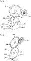
- a training wheel of 48 months (cf. figure 1 ) is coaxial with and integral with the intermediate quarter wheel 42 and drives via a transmission 50, at the rate of one revolution per twelve months, a month wheel 52 which is coaxial with and integral with the month cam 20.
- the intermediate wheel of the quarters 42 meshes with a pinion 54 of fifteen teeth subjected to the action of a jumper of the quarters 56 and forming part of a rolling quarters 58 (cf. figure 5 ).
- the quarter wheel set 58 comprises a month display drive wheel 60 and a season display drive wheel 62, both integral with the pinion 54 (cf. figure 1 ).
- the mobile of the quarters 58 moves one revolution per quarter but, as for the intermediate wheel of the quarters 42, its movement is irregular: a jump every day around midnight between the 19th and the 23rd and a jump at each end of months around midnight, i.e. five jumps per month and fifteen jumps per quarter.
- the month display drive wheel 60 is provided with three teeth 64 located at 120° from each other (only two of which are visible to the figure 1 ). On the last day of each month, one of these teeth 64 moves the pinion 66 of an intermediate month display mobile 68 (cf. figure 2 ) whose wheel 70, integral with the pinion 66, meshes with a month display wheel 72 carrying a month indicator member, such as a needle or a disc, displaying the current month in collaboration with a dial.
- a month display mobile 68 cf. figure 2
- a month display wheel 72 carrying a month indicator member, such as a needle or a disc, displaying the current month in collaboration with a dial.
- Three notches 76 made in said non-toothed upper part to the right of the teeth 64 respectively allow the square 74 and therefore the intermediate month display wheel set 68 to rotate when one of the teeth 64 cooperates with the pinion 66 to drive it.
- the season display drive wheel 62 includes a sector gear 78 with three teeth, the remainder of the season display drive wheel 62 being non-toothed.
- the toothed sector 78 meshes every three months, between the date 19 and the date 23, with a season display star 80 with sixteen teeth to move it by four teeth.
- the 80 Seasons Display Star is subjected to the action of a season jumper 82 and carries a season indicator member, such as a disc bearing symbols of the seasons visible successively through an aperture of the dial or a needle.
- a season indicator member such as a disc bearing symbols of the seasons visible successively through an aperture of the dial or a needle.
- recesses between the teeth of the season display star 80 which are not used for meshing with the season display drive wheel 62 are partially filled with material to accommodate screw 84 securing a season indicator disc to the season display star 80.
- the safety device 88 comprises (cf. figure 6 ) a safety surface 90 substantially concentric with the non-toothed sector 86 and with the axis 92 of the mobile of the quarters 58 and which extends, at a different height, the periphery of the non-toothed sector 86 in the zone of the toothed sector 78.
- safety device 88 is mounted free to rotate around the axis 92 of the quarter wheel 58 but its rotation relative to the season display drive wheel 62 is limited by the cooperation between a pin 94 located in the season display drive wheel 62 and an oblong hole 96 made in the safety member 88.
- the toothing of the season display star 80 has a sufficiently large height to be able to cooperate both with the season display drive wheel 62 and with the safety member 88.
- a tooth 80a of the seasons display star 80 is opposite a portion of the safety surface 90 and a tooth 80b of the seasons display star 80 adjacent to the tooth 80a is opposite another portion of the safety surface 90 or of the non-toothed sector 86 of the season display drive wheel 62 depending on the relative angular position of the wheel 62 and the star 80.
- each jump of the season display star 80 comprises a first jump part where the star 80 is driven by the sector gear 78 against the action of the jumper of the seasons 82 and a second part of the jump caused by the jumper of the seasons 82 after the latter has passed the top of a tooth of the star 80.
- the safety member 88 is integral with the season display drive wheel 62 due to the support of the pin 94 against the wall of the oblong hole 96.
- the safety member 88 uses its mobility with respect to the season display drive wheel 62, against the action of the return spring 98, to let p asser a tooth of the display star of the seasons 80 located in one of the notches 100 (cf. figure 7 ), said tooth then continuing its movement until completing the jump of the 62 seasons display training wheel.
- the various moving parts of the calendar mechanism 1 are indexed with respect to each other so that the actuation of the quarter drive wheel 26 by the upper finger 14, between the 19 and the 23 of each month, does not cause actuation of the seasons display star 80 by the quarters mobile 58 for two consecutive months (the toothed sector 78 then not being facing the seasons display star 80) and causes the season display star 80 to be actuated by the quarter mobile 58 in the third month between the date 19 and the date 23.
- the season display star 80 and the season indicator member she wears therefore turn a quarter turn every three months, between the 19th and the 23rd, and are immobile the rest of the time.
- the 80 seasons display star only moves during part of the last month of each quarter and preferably that part ends before the last day of said last month.
- said part of the last month of each quarter lasts at most ten days, preferably at most seven days, preferably at most five days.
- said part of the last month of each quarter includes, at least partially, the twenty-first day of the last day of each quarter.
- said part of the last month of each quarter begins no earlier than the 18th and ends no later than the 23rd.
- the present invention thus makes it possible to change the information displayed on the current season on the exact dates of season changes or on previously chosen dates, in particular on dates which are distinct from those of the end of the month.
- the display of the season is permanently synchronized with the display of the month so that a desynchronization between the season and the month during a correction of one or more the other or during current operation cannot occur.
- the season display star 80 cannot move backwards without risk of breakage due to the presence of the safety member 88.
- Other parts of the calendar mechanism 1 could be affected by this problem, for example the display of the months if it was of the retrograde type.
- the present invention prohibits the backward time correction around midnight. To do this, as shown in picture 3 , teeth 102 of pinion 8 of date drive wheel set 10 which correspond to a time range including midnight have a flat top 104 oriented tangentially with respect to the axis of pinion 8 and are truncated on the side of their front flank 106.
- the rotation of the winding stem 108 is transmitted to the hour wheel 4 via successively (cf. figure 1 and 2 ) a sliding pinion 110, a first idler 112, a second idler 114, a third idler 116, a timer wheel 118 and a timer gear 120.
- the second and the third idler 114, 116 are coaxial and united. However, one of them is mounted by friction on the common axis of the transmissions 114, 116 in order to be able to disengage the winding stem 108 from the timer in the event of excessive torque exerted by the user backwards on the winding stem. crown 108 while the hours cam 2 is blocked on the pinion 8 of the date drive mobile 10.
- the display of the months and of the seasons can be corrected by means of a corrector acting on a coaxial ratchet secured to the intermediate wheel of the quarters 42.
- the display of the months and seasons can be corrected by winding stem 108 of the watch movement having a dedicated axial position in which rotation of winding stem 108 causes date wheel 16 to rotate independently of hour wheel 4.
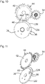
- a security system illustrated in figures 8 to 11 , can be used.
- This safety system comprises, on the periphery of the quarter drive wheel 26, a first safety surface 122 and a second safety surface 124.
- the first safety surface 122 extends angularly in the non-toothed sector of the quarters drive wheel 26 which precedes the two large seasons drive teeth 38, over the entire height of the quarters drive wheel 26.
- the first safety surface 122 is concentric with the axis of the wheel 26 and has a radius R1.
- the second safety surface 124 extends angularly in the non-toothed sector of the quarter drive wheel 26 which follows the two large teeth 38 by projecting a little from this non-toothed sector, but in height it extends only on a lower part of the quarter drive wheel 26.
- the second safety surface 124 is concentric with the axis of the wheel 26 and has a radius R2 greater than the radius R1 and equal to the radius of the head circle of the two large teeth 38.
- An upper part 126 of the non-toothed sector of quarter drive wheel 26 which follows the two large teeth 38 is concentric with the axis of wheel 26 and has a radius R3 less than radius R1. This upper part 126 extends from the toothed sector for training the seasons formed by the two large teeth 38 up to the small tooth 40 for training the months which here is no longer in the form of a tooth but of a transition surface between the first safety surface 122 and said upper part 126.
- the first safety surface 122 serves as a stop respectively for the last tooth 44a and the first tooth 44b of two adjacent toothed sectors 44 of the intermediate wheel of the quarters 42 separated by an empty space 46, thus preventing, in the event of impact, the wheel 42 to de-index relative to the quarters drive wheel 26 in one direction or the other before the passage of the seasons.
- the second safety surface 124 acts as a stop respectively for the second tooth 44c and the first tooth 44d of two adjacent toothed sectors 44 of the intermediate wheel of the quarters 42 (cf. figure 10 ), thus preventing, in the event of an impact, the wheel 42 from de-indexing with respect to the quarter drive wheel 26 in one direction or the other before the passage of the months.
- the last two teeth of each toothed sector 44 have a lower height than that of the first two teeth and are located on a different level from that of the second safety surface 124, namely the level of the upper part 126 and of the transition surface 40, as seen on the figure 9 and 11 .
Abstract
Le mécanisme de calendrier à affichage des saisons pour pièce d'horlogerie comprend une roue d'entraînement (26) dont la position angulaire est représentative du quantième, un organe d'affichage des saisons (80) et un organe d'entraînement d'affichage des saisons (62) agencé pour être entraîné par la roue d'entraînement (26) et pour entraîner l'organe d'affichage des saisons (80) seulement pendant une partie du dernier mois de chaque trimestre.The calendar mechanism with season display for a timepiece comprises a drive wheel (26) whose angular position is representative of the date, a season display member (80) and a display drive member (62) arranged to be driven by the drive wheel (26) and to drive the season display (80) only during part of the last month of each quarter.
Description
La présente invention concerne un mécanisme de calendrier avec affichage des saisons pour pièce d'horlogerie.The present invention relates to a calendar mechanism with display of the seasons for a timepiece.
Des mécanismes de calendrier avec affichage des saisons ont été proposés dans le brevet
Dans le brevet
Dans la demande de brevet
Enfin, dans la demande de brevet
La présente invention vise à proposer un mécanisme de calendrier à affichage des saisons dont l'affichage de la saison courante et des changements de saison puisse être précis.The present invention aims to propose a calendar mechanism with display of the seasons whose display of the current season and the changes of season can be precise.
A cette fin, il est prévu un mécanisme de calendrier selon la revendication 1, des modes de réalisation particuliers étant définis dans les revendications dépendantes.To this end, there is provided a calendar mechanism according to
La présente invention a également pour objet une pièce d'horlogerie, telle qu'une montre-bracelet, une montre de poche ou une pendulette, comprenant un tel mécanisme de calendrier.The present invention also relates to a timepiece, such as a wristwatch, a pocket watch or a clock, comprising such a calendar mechanism.
D'autres caractéristiques et avantages de la présente invention apparaîtront à la lecture de la description détaillée suivante faite en référence aux dessins annexés dans lesquels :
- la
figure 1 est une vue de dessus d'un mécanisme de calendrier selon un mode de réalisation particulier de l'invention ; - la
figure 2 est une vue en perspective du mécanisme de calendrier illustré à lafigure 1 ; - la
figure 3 montre un engrenage unidirectionnel que forment une came des heures et un pignon de mobile d'entraînement de quantième du mécanisme de calendrier illustré à lafigure 1 ; - la
figure 4 est une vue de dessus d'une partie du mécanisme de calendrier illustré à lafigure 1 , dans laquelle certains éléments ont été enlevés pour rendre visible ce qui se trouve dessous ; - la
figure 5 est une vue similaire à lafigure 4 mais montrant en pointillés les parties cachées ; - la
figure 6 est une vue de dessous d'une partie du mécanisme de calendrier illustré à lafigure 1 , montrant une roue d'entraînement d'affichage des saisons, un organe de sécurité et une étoile d'affichage des saisons dans un état de repos ; - la
figure 7 est une vue de dessous de la partie illustrée à lafigure 6 , montrant la roue d'entraînement d'affichage des saisons, l'organe de sécurité et l'étoile d'affichage des saisons pendant l'entraînement de l'étoile d'affichage des saisons ; - les
figures 8 et 9 sont respectivement une vue de dessus et une vue en perspective d'une partie d'un mécanisme de calendrier selon un autre mode de réalisation de l'invention, montrant une roue d'entraînement des trimestres et une roue intermédiaire des trimestres avant le passage d'une saison ; - les
figures 10 et 11 sont respectivement une vue de dessus et une vue en perspective de la partie illustrée auxfigures 8 et 9 , montrant la roue d'entraînement des trimestres et la roue intermédiaire des trimestres avant le passage d'un mois.
- the
figure 1 is a top view of a calendar mechanism according to a particular embodiment of the invention; - the
figure 2 is a perspective view of the calendar mechanism shown infigure 1 ; - the
picture 3 shows a one-way gear formed by an hour cam and a pinion of the date drive mobile pinion of the calendar mechanism illustrated infigure 1 ; - the
figure 4 is a top view of part of the calendar mechanism shown infigure 1 , in which some elements have been removed to make what is underneath visible; - the
figure 5 is a view similar to thefigure 4 but showing in dotted lines the hidden parts; - the
figure 6 is a bottom view of part of the calendar mechanism shown infigure 1 , showing a season display drive wheel, a safety member and a season display star in a state of rest; - the
figure 7 is a bottom view of the part shown infigure 6 , showing the season display drive wheel, the safety member and the season display star during the drive of the season display star; - them
figures 8 and 9 are respectively a top view and a perspective view of part of a calendar mechanism according to another embodiment of the invention, showing a quarter driving wheel and an intermediate quarter wheel before the passage of 'a season ; - them
figures 10 and 11 are respectively a top view and a perspective view of the part illustrated infigures 8 and 9 , showing the quarters driving wheel and the intermediate quarters wheel before the passage of a month.
En référence aux
Outre le pignon 8, le mobile d'entraînement de quantième 10 comprend (cf.
Une bascule des mois 22 est montée pivotante sur la planche de la roue de quantième 16 et comprend un bec 22a pouvant coopérer avec la périphérie de la came des mois 20. La bascule des mois 22 est libre en rotation mais son débattement est limité dans un sens par la came des mois 20 et dans l'autre sens par une goupille 22b chassée dans la planche de la roue de quantième 16. Lorsque la bascule des mois 22 appuie par son bec 22a contre une levée de la came des mois 20, une dent 24 de la bascule des mois 22 est superposée à la denture de la roue de quantième 16 et se trouve ainsi sur la trajectoire du doigt supérieur 14 lorsque la roue de quantième 16 est dans la position angulaire correspondant au quantième 30. Lorsque le bec 22a repose dans un creux de la came des mois 20, la dent 24 est rétractée par rapport à la denture de la roue de quantième 16 et ne peut pas coopérer avec le doigt supérieur 14.A
Ainsi, pendant les mois de trente et un jours, le doigt supérieur 14 ne peut pas agir sur la roue de quantième 16 et le passage du quantième 30 au quantième 31 s'effectue par l'action du doigt inférieur 12, comme pour les autres jours. En effet, même si la dent 24 se trouve superposée à la denture de la roue de quantième 16, elle s'efface dès qu'elle rencontre le doigt supérieur 14 empêchant ce dernier d'entraîner la roue de quantième 16. Le 30 des mois de trente jours, en revanche, aux environs de minuit, le doigt supérieur 14 coopère avec la dent 24 de la bascule des mois 22, qui est alors en appui par son bec 22a sur une levée de la came des mois 20, pour déplacer la roue de quantième 16 d'un premier pas pour le passage du 30 au 31, puis le doigt inférieur 12 coopère avec la denture de la roue de quantième 16 pour la faire avancer d'un pas supplémentaire et assurer le passage du 31 au 1er.Thus, during the months of thirty-one days, the
Chaque déplacement de la roue de quantième 16 est communiqué, par l'intermédiaire d'un rouage (non représenté), à un organe indicateur de quantième (non représenté) tel qu'une couronne, un disque ou une aiguille.Each movement of the
Le mobile d'entraînement de quantième 10, la roue de quantième 16 et la bascule des mois 22 font partie d'un mécanisme de quantième annuel basé sur le principe exposé dans le brevet
Une roue d'entraînement des trimestres 26 est montée coaxialement à la roue de quantième 16. La roue d'entraînement des trimestres 26 peut tourner par rapport à la roue de quantième 16 sur un certain angle seulement, défini par deux ouvertures 28 pratiquées dans la roue de quantième 16 et que traversent deux goupilles 30 respectives chassées d'un côté dans la roue d'entraînement des trimestres 26 et de l'autre côté dans une pièce des saisons 32. La pièce des saisons 32 comporte un secteur denté 34 à quatre dents superposé à la denture de la roue de quantième 16. Un ressort de rappel 36 monté sur la planche de la roue de quantième 16 agit sur la pièce des saisons 32 pour qu'une au moins des goupilles 30 soit maintenue en appui contre la paroi de l'ouverture 28 correspondante. Cet appui permet à la roue de quantième 16 d'entraîner la roue d'entraînement des trimestres 26.A
La pièce des saisons 32 est positionnée de telle sorte qu'au quantième 19 de chaque mois, aux alentours de minuit, le doigt supérieur 14 rencontre la première dent de la pièce des saisons 32 et coopère avec elle pour déplacer la roue d'entraînement des trimestres 26 par rapport à la roue de quantième 16 d'un angle correspondant à un pas de la roue de quantième 16, contre l'action du ressort de rappel 36. Puis, toujours le 19 aux alentours de minuit, le doigt inférieur 12 agit sur la denture de la roue de quantième 16 pour faire avancer la roue de quantième 16 d'un pas et rattraper la roue d'entraînement des trimestres 26. Le 20 aux alentours de minuit le doigt supérieur 14 rencontre la deuxième dent de la pièce des saisons 32 et coopère avec elle pour déplacer la roue d'entraînement des trimestres 26 par rapport à la roue de quantième 16 d'un angle correspondant à un pas de la roue de quantième 16, contre l'action du ressort de rappel 36. Ensuite, le doigt inférieur 12 agit sur la denture de la roue de quantième 16 pour faire avancer la roue de quantième 16 d'un pas et rattraper la roue d'entraînement des trimestres 26. La même opération se produit le 21 entre le doigt supérieur 14 et la troisième dent de la pièce des saisons 32 et entre le doigt inférieur 12 et la denture de la roue de quantième 16, puis le 22 entre le doigt supérieur 14 et la quatrième dent de la pièce des saisons 32 et entre le doigt inférieur 12 et la denture de la roue de quantième 16. Les autres jours, c'est la roue de quantième 16 qui entraîne la roue d'entraînement des trimestres 26 par l'appui d'au moins une des goupilles 30 contre la paroi de l'ouverture 28 correspondante.The
Ainsi, la roue d'entraînement des trimestres 26 est entraînée d'un trente et unième de tour chaque jour, comme la roue de quantième 16, mais entre le 19 et le 23 ce déplacement s'effectue de manière temporellement décalée par rapport à la roue de quantième 16. Ceci permet de répartir la consommation d'énergie. En effet, comme on le verra plus loin, les déplacements de la roue d'entraînement des trimestres 26 entre le 19 et le 23 provoquent chaque trimestre le déplacement d'un affichage des saisons. Il est avantageux, pour éviter de grands pics de consommation d'énergie, que les sauts de quantième et ceux de l'affichage des saisons se produisent à des instants différents. Dans une variante, toutefois, la pièce des saisons 32 pourrait être supprimée et la roue d'entraînement des trimestres 26 pourrait être rendue solidaire de la roue de quantième 16.Thus, the
La roue d'entraînement des trimestres 26 comporte un secteur denté d'entraînement des saisons, formé de deux grandes dents 38. La roue d'entraînement des trimestres 26 comporte en outre une petite dent 40 d'entraînement des mois. Les deux grandes dents 38 sont dimensionnées pour faire avancer de quatre pas - le premier du 19 au 20, le deuxième du 20 au 21, le troisième du 21 au 22 et le quatrième du 22 au 23 - une roue intermédiaire des trimestres 42. La petite dent 40 fait avancer d'un pas la roue intermédiaire des trimestres 42 à chaque fin de mois. La roue intermédiaire des trimestres 42 comporte six secteurs dentés 44 de quatre dents chacun séparés par six espaces vides 46 occupant chacun la place d'une dent. Ces espaces vides 46 ont pour fonction de permettre à la petite dent 40 d'attraper à chaque fois la bonne dent de la roue intermédiaire des trimestres 42. Ils ne gênent pas l'entraînement de la roue intermédiaire des trimestres 42 par les deux grandes dents 38.The
La roue intermédiaire des trimestres 42 effectue un tour en six mois. Une roue d'entraînement des mois 48 (cf.
La roue intermédiaire des trimestres 42 engrène avec un pignon 54 de quinze dents soumis à l'action d'un sautoir des trimestres 56 et faisant partie d'un mobile des trimestres 58 (cf.
La roue d'entraînement d'affichage des mois 60 est pourvue de trois dents 64 situées à 120° les unes des autres (dont seulement deux sont visibles à la
La roue d'entraînement d'affichage des saisons 62 comprend un secteur denté 78 à trois dents, le reste de la roue d'entraînement d'affichage des saisons 62 étant non denté. Le secteur denté 78 engrène tous les trois mois, entre le quantième 19 et le quantième 23, avec une étoile d'affichage des saisons 80 à seize dents pour la déplacer de quatre dents. L'étoile d'affichage des saisons 80 est soumise à l'action d'un sautoir des saisons 82 et porte un organe indicateur des saisons, tel qu'un disque portant des symboles des saisons visibles successivement à travers un guichet du cadran ou une aiguille. Dans l'exemple représenté, des creux entre les dents de l'étoile d'affichage des saisons 80 qui ne sont pas utilisés pour l'engrènement avec la roue d'entraînement d'affichage des saisons 62 sont partiellement remplis de matière pour accueillir des vis 84 fixant un disque indicateur des saisons à l'étoile d'affichage des saisons 80.The season
Lorsque l'étoile d'affichage des saisons 80 est en regard du secteur non denté de la roue d'entraînement d'affichage des saisons 62, désigné par 86, sa denture bute immédiatement contre ce secteur non denté 86 en cas de choc, ce qui l'empêche de tourner intempestivement. En revanche, pendant les jours où elle est en prise avec le secteur denté 78, l'étoile d'affichage des saisons 80 pourrait, sous l'effet d'un choc et de son inertie, devenir menante et entraîner le mobile des trimestres 58. Pour éviter cela, un organe de sécurité 88 complète le mobile des trimestres 58.When the
L'organe de sécurité 88 comprend (cf.
La denture de l'étoile d'affichage des saisons 80 présente une hauteur suffisamment grande pour pouvoir coopérer à la fois avec la roue d'entraînement d'affichage des saisons 62 et avec l'organe de sécurité 88. Lorsque le secteur denté 78 et l'étoile d'affichage des saisons 80 sont en prise et immobiles, comme dans la configuration illustrée à la
La mobilité en rotation de l'organe de sécurité 88 par rapport à la roue d'entraînement d'affichage des saisons 62 permet à l'organe de sécurité 88 de ne pas gêner l'entraînement de l'étoile d'affichage des saisons 80 par la roue d'entraînement d'affichage des saisons 62. En effet, chaque saut de l'étoile d'affichage des saisons 80 comprend une première partie de saut où l'étoile 80 est entraînée par le secteur denté 78 contre l'action du sautoir des saisons 82 et une deuxième partie de saut provoquée par le sautoir des saisons 82 après que ce dernier a passé le sommet d'une dent de l'étoile 80. Durant la première partie de saut, l'organe de sécurité 88 est solidaire de la roue d'entraînement d'affichage des saisons 62 du fait de l'appui de la goupille 94 contre la paroi du trou oblong 96. Durant la deuxième partie de saut, l'organe de sécurité 88 utilise sa mobilité par rapport à la roue d'entraînement d'affichage des saisons 62, contre l'action du ressort de rappel 98, pour laisser passer une dent de l'étoile d'affichage des saisons 80 se trouvant dans une des encoches 100 (cf.
On aura compris que les différents organes mobiles du mécanisme de calendrier 1 sont indexés les uns par rapport aux autres de telle sorte que l'actionnement de la roue d'entraînement de trimestre 26 par le doigt supérieur 14, entre le 19 et le 23 de chaque mois, ne provoque pas d'actionnement de l'étoile d'affichage des saisons 80 par le mobile des trimestres 58 pendant deux mois consécutifs (le secteur denté 78 n'étant alors pas en regard de l'étoile d'affichage des saisons 80) et provoque un actionnement de l'étoile d'affichage des saisons 80 par le mobile des trimestres 58 le troisième mois entre le quantième 19 et le quantième 23. L'étoile d'affichage des saisons 80 et l'organe indicateur des saisons qu'elle porte tournent donc d'un quart de tour tous les trois mois, entre le 19 et le 23, et sont immobiles le reste du temps.It will be understood that the various moving parts of the
Il va de soi que l'on pourrait modifier le mécanisme de calendrier 1 pour que l'étoile d'affichage des saisons 80 se déplace d'un quart de tour en quatre sauts entre le 18 et le 22, en deux sauts entre le 20 et le 22, en un seul saut entre le 20 et le 21 ou en un seul saut entre le 21 ou le 22, par exemple, plutôt qu'en quatre sauts entre le 19 et le 23. De manière générale, dans la présente invention, l'étoile d'affichage des saisons 80 se déplace seulement pendant une partie du dernier mois de chaque trimestre et, de préférence, cette partie se termine avant le dernier jour dudit dernier mois. De préférence, ladite partie du dernier mois de chaque trimestre dure au plus dix jours, de préférence au plus sept jours, de préférence au plus cinq jours. De préférence, ladite partie du dernier mois de chaque trimestre inclut, au moins partiellement, le vingt et unième jour du dernier jour de chaque trimestre. De préférence, ladite partie du dernier mois de chaque trimestre commence au plus tôt le 18 et se termine au plus tard le 23.It stands to reason that one could modify the 1 calendar mechanism so that the 80 seasons display star moves a quarter turn in four jumps between the 18th and 22nd, in two jumps between the 20th and 22, in a single jump between 20 and 21 or in a single jump between 21 or 22, for example, rather than in four jumps between 19 and 23. Generally, in the present invention , the 80 seasons display star only moves during part of the last month of each quarter and preferably that part ends before the last day of said last month. Preferably, said part of the last month of each quarter lasts at most ten days, preferably at most seven days, preferably at most five days. Preferably, said part of the last month of each quarter includes, at least partially, the twenty-first day of the last day of each quarter. Preferably, said part of the last month of each quarter begins no earlier than the 18th and ends no later than the 23rd.
On aura également compris que les différents organes mobiles du mécanisme de calendrier 1 sont indexés les uns par rapport aux autres de telle sorte que l'actionnement de la roue d'entraînement de trimestre 26 par le doigt inférieur 12 produise un effet sur la roue d'affichage des mois 72 seulement lors de la transition du dernier jour de chaque mois au premier jour du mois suivant.It will also be understood that the various moving parts of the
La présente invention permet ainsi de changer l'information affichée sur la saison courante aux dates exactes de changements de saison ou à des dates préalablement choisies, en particulier à des dates qui sont distinctes de celles des fins de mois. En outre, grâce aux organes de sécurité 74 et 88 l'affichage de la saison est en permanence synchronisé avec l'affichage du mois de sorte qu'une désynchronisation entre la saison et le mois lors d'une correction de l'un ou de l'autre ou lors du fonctionnement courant ne peut pas se produire.The present invention thus makes it possible to change the information displayed on the current season on the exact dates of season changes or on previously chosen dates, in particular on dates which are distinct from those of the end of the month. In addition, thanks to the
Dans le mécanisme de calendrier 1 tel que décrit ci-dessus, l'étoile d'affichage des saisons 80 ne peut pas se mouvoir en arrière sans risque de casse du fait de la présence de l'organe de sécurité 88. D'autres parties du mécanisme de calendrier 1 pourraient être concernées par ce problème, par exemple l'affichage des mois s'il était de type rétrograde. Afin de protéger le mécanisme de calendrier 1, la présente invention interdit la correction de l'heure en arrière aux alentours de minuit. Pour ce faire, comme illustré à la
La rotation de la tige de remontoir 108, lorsque cette dernière se trouve dans une position axiale de mise à l'heure, est transmise à la roue des heures 4 via successivement (cf.
Dans un exemple de réalisation, l'affichage des mois et des saisons peut être corrigé au moyen d'un correcteur agissant sur un rochet coaxial et solidaire de la roue intermédiaire des trimestres 42. Dans un autre exemple de réalisation, l'affichage des mois et des saisons peut être corrigé par la tige de remontoir 108 du mouvement horloger ayant une position axiale dédiée dans laquelle une rotation de la tige de remontoir 108 fait tourner la roue de quantième 16 indépendamment de la roue des heures 4. Dans cet autre exemple de réalisation, il peut être utile d'empêcher toute désynchronisation entre la roue intermédiaire des trimestres 42 et la roue de quantième 16. A cet effet, un système de sécurité, illustré aux
Ce système de sécurité comprend, sur la périphérie de la roue d'entraînement des trimestres 26, une première surface de sécurité 122 et une deuxième surface de sécurité 124. La première surface de sécurité 122 s'étend angulairement dans le secteur non denté de la roue d'entraînement des trimestres 26 qui précède les deux grandes dents 38 d'entraînement des saisons, sur toute la hauteur de la roue d'entraînement des trimestres 26. En outre, la première surface de sécurité 122 est concentrique avec l'axe de la roue 26 et présente un rayon R1. La deuxième surface de sécurité 124 s'étend angulairement dans le secteur non denté de la roue d'entraînement des trimestres 26 qui suit les deux grandes dents 38 en dépassant un peu de ce secteur non denté, mais en hauteur elle s'étend seulement sur une partie inférieure de la roue d'entraînement des trimestres 26. En outre, la deuxième surface de sécurité 124 est concentrique avec l'axe de la roue 26 et présente un rayon R2 supérieur au rayon R1 et égal au rayon du cercle de tête des deux grandes dents 38. Une partie supérieure 126 du secteur non denté de la roue d'entraînement des trimestres 26 qui suit les deux grandes dents 38 est concentrique avec l'axe de la roue 26 et présente un rayon R3 inférieur au rayon R1. Cette partie supérieure 126 s'étend depuis le secteur denté d'entraînement des saisons que forment les deux grandes dents 38 jusqu'à la petite dent 40 d'entraînement des mois qui ici n'est plus sous la forme d'une dent mais d'une surface de transition entre la première surface de sécurité 122 et ladite partie supérieure 126.This safety system comprises, on the periphery of the
Comme on peut le voir à la
Pour permettre ces coopérations entre la denture de la roue intermédiaire des trimestres 42 et les surfaces de sécurité 122, 124 ainsi qu'entre la denture de la roue intermédiaire des trimestres 42 et celle de la roue d'entraînement des trimestres 26, les deux dernières dents de chaque secteur denté 44 ont une hauteur inférieure à celle des deux premières dents et se situent sur un niveau différent de celui de la deuxième surface de sécurité 124, à savoir le niveau de la partie supérieure 126 et de la surface de transition 40, comme visible sur les
La présente invention a été décrite ci-dessus à titre d'exemple uniquement. Il va de soi que des modifications pourraient être faites sans sortir du cadre de l'invention revendiquée.The present invention has been described above by way of example only. It goes without saying that modifications could be made without departing from the scope of the claimed invention.
Claims (15)
Priority Applications (4)
| Application Number | Priority Date | Filing Date | Title |
|---|---|---|---|
| EP21179694.1A EP4105732A1 (en) | 2021-06-16 | 2021-06-16 | Calendar mechanism with display of the seasons for a timepiece |
| EP22733480.2A EP4356203A1 (en) | 2021-06-16 | 2022-06-15 | Calendar mechanism with season display for a timepiece |
| CN202280042768.8A CN117501188A (en) | 2021-06-16 | 2022-06-15 | Calendar mechanism with season display function for timepiece |
| PCT/IB2022/055525 WO2022264046A1 (en) | 2021-06-16 | 2022-06-15 | Calendar mechanism with season display for a timepiece |
Applications Claiming Priority (1)
| Application Number | Priority Date | Filing Date | Title |
|---|---|---|---|
| EP21179694.1A EP4105732A1 (en) | 2021-06-16 | 2021-06-16 | Calendar mechanism with display of the seasons for a timepiece |
Publications (1)
| Publication Number | Publication Date |
|---|---|
| EP4105732A1 true EP4105732A1 (en) | 2022-12-21 |
Family
ID=76483192
Family Applications (2)
| Application Number | Title | Priority Date | Filing Date |
|---|---|---|---|
| EP21179694.1A Withdrawn EP4105732A1 (en) | 2021-06-16 | 2021-06-16 | Calendar mechanism with display of the seasons for a timepiece |
| EP22733480.2A Pending EP4356203A1 (en) | 2021-06-16 | 2022-06-15 | Calendar mechanism with season display for a timepiece |
Family Applications After (1)
| Application Number | Title | Priority Date | Filing Date |
|---|---|---|---|
| EP22733480.2A Pending EP4356203A1 (en) | 2021-06-16 | 2022-06-15 | Calendar mechanism with season display for a timepiece |
Country Status (3)
| Country | Link |
|---|---|
| EP (2) | EP4105732A1 (en) |
| CN (1) | CN117501188A (en) |
| WO (1) | WO2022264046A1 (en) |
Citations (7)
| Publication number | Priority date | Publication date | Assignee | Title |
|---|---|---|---|---|
| US563268A (en) | 1893-03-06 | 1896-07-07 | Perpetual calendar for watches or clocks | |
| CH685585GA3 (en) | 1994-01-21 | 1995-08-31 | Patek Philippe Sa | Watch day display mechanism |
| DE102008031441A1 (en) | 2008-07-04 | 2010-01-07 | Momoplus Gmbh | Clock, has dial, additional season indicator indicating four seasons, and second hand, hour hand and minute indicator, which are provided for indicating time of day, where hand indicates day and is provided at dial |
| JP2010121943A (en) * | 2008-11-17 | 2010-06-03 | Seiko Epson Corp | Timepiece |
| CH708648A2 (en) * | 2013-09-25 | 2015-04-30 | Jean-Pierre Horvath | Watch including an astronomical indication. |
| EP3327516A1 (en) | 2016-10-27 | 2018-05-30 | Blancpain SA | Mechanism for displaying a temporal or seasonal period |
| WO2019193430A1 (en) | 2018-04-04 | 2019-10-10 | Patek Philippe Sa Geneve | Annual calendar mechanism |
-
2021
- 2021-06-16 EP EP21179694.1A patent/EP4105732A1/en not_active Withdrawn
-
2022
- 2022-06-15 WO PCT/IB2022/055525 patent/WO2022264046A1/en active Application Filing
- 2022-06-15 EP EP22733480.2A patent/EP4356203A1/en active Pending
- 2022-06-15 CN CN202280042768.8A patent/CN117501188A/en active Pending
Patent Citations (7)
| Publication number | Priority date | Publication date | Assignee | Title |
|---|---|---|---|---|
| US563268A (en) | 1893-03-06 | 1896-07-07 | Perpetual calendar for watches or clocks | |
| CH685585GA3 (en) | 1994-01-21 | 1995-08-31 | Patek Philippe Sa | Watch day display mechanism |
| DE102008031441A1 (en) | 2008-07-04 | 2010-01-07 | Momoplus Gmbh | Clock, has dial, additional season indicator indicating four seasons, and second hand, hour hand and minute indicator, which are provided for indicating time of day, where hand indicates day and is provided at dial |
| JP2010121943A (en) * | 2008-11-17 | 2010-06-03 | Seiko Epson Corp | Timepiece |
| CH708648A2 (en) * | 2013-09-25 | 2015-04-30 | Jean-Pierre Horvath | Watch including an astronomical indication. |
| EP3327516A1 (en) | 2016-10-27 | 2018-05-30 | Blancpain SA | Mechanism for displaying a temporal or seasonal period |
| WO2019193430A1 (en) | 2018-04-04 | 2019-10-10 | Patek Philippe Sa Geneve | Annual calendar mechanism |
Also Published As
| Publication number | Publication date |
|---|---|
| WO2022264046A1 (en) | 2022-12-22 |
| CN117501188A (en) | 2024-02-02 |
| EP4356203A1 (en) | 2024-04-24 |
Similar Documents
| Publication | Publication Date | Title |
|---|---|---|
| EP1586962B1 (en) | Ewiger Kalendermechanismus | |
| EP0756217B1 (en) | Annual calendar mechanism for timepieces | |
| EP1785783B1 (en) | Annual calendar mechanism for a clock movement | |
| EP2329325B1 (en) | Display mechanism for a timepiece used to display or not the current time | |
| EP2428856B1 (en) | Timepiece | |
| CH681761B5 (en) | Part of clockwork mechanical and / or electromechanical, provided with automatic retrograde moving display means. | |
| EP0987609B1 (en) | Annual calendar mechanism for clockwork-movement | |
| EP1536299B1 (en) | Calendar mechanism for a watch comprising two superposed date annuli | |
| EP1012675B1 (en) | Train of clockwork with perpetual julian date | |
| CH699794B1 (en) | An aid in maintaining the position of a ring date indicator timepiece. | |
| EP4105732A1 (en) | Calendar mechanism with display of the seasons for a timepiece | |
| CH691088A5 (en) | mechanism at the time of a watch with perpetual calendar movement. | |
| EP3460588B1 (en) | Date mechanism | |
| EP1734419B1 (en) | Timepiece with calendar mechanismus | |
| EP3989011B1 (en) | Retrograde display mechanism for a timepiece of the driving type provided with a lever for disengagement of the display | |
| EP3629102B1 (en) | Display mechanism with single window | |
| EP3667435B1 (en) | System for adjusting the position of a first toothed moving part relative to a support on which the first toothed moving part is pivotably mounted, and timepiece comprising such a system | |
| EP4254079A1 (en) | Mechanism for displaying the phases of the moon for a timepiece | |
| CH718166A2 (en) | Drag-type retrograde horological display mechanism equipped with a display disengagement rocker. | |
| CH719558A2 (en) | Clock movement with a moon phase display mechanism. | |
| CH719977A1 (en) | Watch mechanism with jumping display | |
| CH718804A1 (en) | Perpetual or annual calendar mechanism. | |
| CH715566B1 (en) | System comprising a first toothed mobile whose angular position can be adjusted relative to a support on which the first toothed mobile is pivotally mounted, timepiece comprising such a system and large date display mechanism. | |
| EP3644130A1 (en) | Date mechanism | |
| CH716385B1 (en) | Clockwork drive and blocking mechanism for a jumping mobile. |
Legal Events
| Date | Code | Title | Description |
|---|---|---|---|
| PUAI | Public reference made under article 153(3) epc to a published international application that has entered the european phase |
Free format text: ORIGINAL CODE: 0009012 |
|
| STAA | Information on the status of an ep patent application or granted ep patent |
Free format text: STATUS: THE APPLICATION HAS BEEN PUBLISHED |
|
| AK | Designated contracting states |
Kind code of ref document: A1 Designated state(s): AL AT BE BG CH CY CZ DE DK EE ES FI FR GB GR HR HU IE IS IT LI LT LU LV MC MK MT NL NO PL PT RO RS SE SI SK SM TR |
|
| P01 | Opt-out of the competence of the unified patent court (upc) registered |
Effective date: 20230521 |
|
| STAA | Information on the status of an ep patent application or granted ep patent |
Free format text: STATUS: THE APPLICATION IS DEEMED TO BE WITHDRAWN |
|
| 18D | Application deemed to be withdrawn |
Effective date: 20230622 |