EP4105704A1 - Light irradiation device and sample observation apparatus - Google Patents
Light irradiation device and sample observation apparatus Download PDFInfo
- Publication number
- EP4105704A1 EP4105704A1 EP21814612.4A EP21814612A EP4105704A1 EP 4105704 A1 EP4105704 A1 EP 4105704A1 EP 21814612 A EP21814612 A EP 21814612A EP 4105704 A1 EP4105704 A1 EP 4105704A1
- Authority
- EP
- European Patent Office
- Prior art keywords
- light
- focusing
- aperture mask
- irradiation device
- axis
- Prior art date
- Legal status (The legal status is an assumption and is not a legal conclusion. Google has not performed a legal analysis and makes no representation as to the accuracy of the status listed.)
- Granted
Links
Images




Classifications
-
- G—PHYSICS
- G02—OPTICS
- G02B—OPTICAL ELEMENTS, SYSTEMS OR APPARATUS
- G02B21/00—Microscopes
- G02B21/0004—Microscopes specially adapted for specific applications
- G02B21/002—Scanning microscopes
- G02B21/0024—Confocal scanning microscopes (CSOMs) or confocal "macroscopes"; Accessories which are not restricted to use with CSOMs, e.g. sample holders
- G02B21/0032—Optical details of illumination, e.g. light-sources, pinholes, beam splitters, slits, fibers
-
- G—PHYSICS
- G02—OPTICS
- G02B—OPTICAL ELEMENTS, SYSTEMS OR APPARATUS
- G02B21/00—Microscopes
- G02B21/06—Means for illuminating specimens
-
- G—PHYSICS
- G01—MEASURING; TESTING
- G01N—INVESTIGATING OR ANALYSING MATERIALS BY DETERMINING THEIR CHEMICAL OR PHYSICAL PROPERTIES
- G01N21/00—Investigating or analysing materials by the use of optical means, i.e. using sub-millimetre waves, infrared, visible or ultraviolet light
- G01N21/62—Systems in which the material investigated is excited whereby it emits light or causes a change in wavelength of the incident light
- G01N21/63—Systems in which the material investigated is excited whereby it emits light or causes a change in wavelength of the incident light optically excited
- G01N21/64—Fluorescence; Phosphorescence
- G01N21/645—Specially adapted constructive features of fluorimeters
- G01N21/6456—Spatial resolved fluorescence measurements; Imaging
-
- G—PHYSICS
- G02—OPTICS
- G02B—OPTICAL ELEMENTS, SYSTEMS OR APPARATUS
- G02B21/00—Microscopes
- G02B21/36—Microscopes arranged for photographic purposes or projection purposes or digital imaging or video purposes including associated control and data processing arrangements
- G02B21/365—Control or image processing arrangements for digital or video microscopes
- G02B21/367—Control or image processing arrangements for digital or video microscopes providing an output produced by processing a plurality of individual source images, e.g. image tiling, montage, composite images, depth sectioning, image comparison
-
- G—PHYSICS
- G02—OPTICS
- G02B—OPTICAL ELEMENTS, SYSTEMS OR APPARATUS
- G02B27/00—Optical systems or apparatus not provided for by any of the groups G02B1/00 - G02B26/00, G02B30/00
- G02B27/09—Beam shaping, e.g. changing the cross-sectional area, not otherwise provided for
- G02B27/0911—Anamorphotic systems
-
- G—PHYSICS
- G02—OPTICS
- G02B—OPTICAL ELEMENTS, SYSTEMS OR APPARATUS
- G02B27/00—Optical systems or apparatus not provided for by any of the groups G02B1/00 - G02B26/00, G02B30/00
- G02B27/09—Beam shaping, e.g. changing the cross-sectional area, not otherwise provided for
- G02B27/0927—Systems for changing the beam intensity distribution, e.g. Gaussian to top-hat
-
- G—PHYSICS
- G02—OPTICS
- G02B—OPTICAL ELEMENTS, SYSTEMS OR APPARATUS
- G02B27/00—Optical systems or apparatus not provided for by any of the groups G02B1/00 - G02B26/00, G02B30/00
- G02B27/09—Beam shaping, e.g. changing the cross-sectional area, not otherwise provided for
- G02B27/0938—Using specific optical elements
- G02B27/095—Refractive optical elements
- G02B27/0955—Lenses
- G02B27/0966—Cylindrical lenses
-
- G—PHYSICS
- G02—OPTICS
- G02B—OPTICAL ELEMENTS, SYSTEMS OR APPARATUS
- G02B27/00—Optical systems or apparatus not provided for by any of the groups G02B1/00 - G02B26/00, G02B30/00
- G02B27/09—Beam shaping, e.g. changing the cross-sectional area, not otherwise provided for
- G02B27/0938—Using specific optical elements
- G02B27/0988—Diaphragms, spatial filters, masks for removing or filtering a part of the beam
-
- G—PHYSICS
- G01—MEASURING; TESTING
- G01N—INVESTIGATING OR ANALYSING MATERIALS BY DETERMINING THEIR CHEMICAL OR PHYSICAL PROPERTIES
- G01N2201/00—Features of devices classified in G01N21/00
- G01N2201/06—Illumination; Optics
- G01N2201/061—Sources
- G01N2201/06113—Coherent sources; lasers
Definitions
- the present disclosure relates to a light irradiation device and a sample observation apparatus.
- the sample observation apparatus of this Patent Literature 1 is configured to include an irradiation optical system that irradiates a sample with planar light, a scanning unit that scans a sample for an irradiation face of planar light, and an imaging optical system that has an observation axis inclined with respect to the irradiation face and forms an image of observation light generated in a sample in accordance with irradiation of planar light. Then, a plurality of pieces of partial image data corresponding to a part of an optical image according to observation light formed as an image by the imaging optical system are acquired, and observation image data of a sample is generated on the basis of such partial image data.
- Patent Literature 1 Japanese Unexamined Patent Publication No. 2018-063292
- the planar light used in the sample observation apparatus described above is formed by focusing light emitted from a light source using a light focusing element such as a cylindrical lens or the like.
- a light focusing element such as a cylindrical lens or the like.
- coherent light for example, such as laser light is light having coherence, and thus interference fringes due to diffraction on the edge of the aperture mask are generated, and there is concern that a radiation illuminance distribution of the planar light may become non-uniform.
- the present disclosure is for solving the problems described above, and an object thereof is to provide a light irradiation device and a sample observation apparatus capable of outputting planar light having a uniform radiation illuminance distribution.
- a light irradiation device including: a light source configured to output light having coherence; a light focusing element having a focusing axis and a non-focusing axis intersecting with the focusing axis and configured to focus the light on a focusing line so as to generate planar light; and an aperture mask having an opening part that limits a part of luminous fluxes of the light transmitted from the light source to the light focusing element, in which the opening part of the aperture mask has opening edges disposed to extend in a direction along the focusing axis of the light focusing element, and, in a case in which the opening edges are projected onto the focusing line, corresponding projected portions have linear spreads.
- this light irradiation device can output planar light having a uniform radiation illuminance distribution.
- the opening part may have an asymmetrical shape with respect to the focusing line.
- the opening edges may have shapes protruding to an outer side with respect to the focusing line.
- the opening part may have a hexagonal shape. According to such a configuration, interference fringes due to diffraction in the opening edges are further suppressed, and the radiation illuminance distribution of the planar light is further uniformized.
- the opening part may have a trapezoid shape.
- the opening edges may have a zigzag shape.
- the opening edges may have a shape protruding to an outer side of the focusing line. Also in such a configuration, interference fringes due to diffraction in the opening edges are further suppressed, and the radiation illuminance distribution of the planar light is further uniformized.
- the opening part may have a quadrangle shape, and the opening edges may intersect with the focusing axis at a predetermined angle. Also in such a configuration, interference fringes due to diffraction in the opening edges are further suppressed, and the radiation illuminance distribution of the planar light is further uniformized.
- the light source may be a light source that outputs laser light as the light.
- the laser light is light, from which high radiation illuminance can be acquired, but has high coherence, and interference fringes due to diffraction in edges of an aperture mask may be easily generated.
- planar light having a uniform radiation illuminance distribution can be appropriately output.
- a sample observation apparatus including: the light irradiation device described above; and a detection unit configured to detect observation light generated in a sample in accordance with irradiation of the planar light from the light irradiation device.
- planar light having a uniform radiation illuminance distribution can be output.
- Fig. 1 is a schematic configuration diagram illustrating a sample observation apparatus according to an embodiment.
- This sample observation apparatus 1 is an apparatus that acquires observation image data of the inside of a sample S by irradiating the sample S with planar light L1 and forming an image of light (for example, fluorescence, scattering light, or the like) generated inside the sample S in accordance with the irradiation of the planar light L1 on an imaging surface.
- a sample observation apparatus 1 of such a type there is a slide scanner that acquires and displays an image of a sample S stored in a slide glass, a plate reader that acquires image data of a sample S stored on a micro plate and analyzes the image data, or the like.
- the sample S that is an observation target there is a cell, a tissue, or an organ of a person or an animal, an animal or a plant, a cell, an organ, or the like of a plant, or the like.
- the sample S may be contained in a solution, a gel, or a material of which a refractive index is different from that of the sample S.
- the sample observation apparatus 1 is configured to include a light irradiation device 2, a scanning unit 4, an imaging optical system 5, an image acquiring unit (a detection unit) 6, and a computer 7.
- the light irradiation device 2 is a device that outputs planar light L1 to irradiate a sample S.
- the planar light L1 is light that can be acquired by shaping laser light or low coherent light into a planar shape.
- the planar light L1 output from the light irradiation device 2 advances along an optical axis PI, and a sample S is irradiated therewith.
- observation light L2 is generated on an irradiation surface R of the planar light L1.
- the observation light L2 is fluorescence excited by the planar light L1, scattering light of the planar light L1, or a diffused reflected light of the planar light L1.
- the scanning unit 4 is a mechanism that scans a sample S for the irradiation surface R of the planar light L1.
- the scanning unit 4 is configured using a moving stage 12 that moves a sample container 11 storing a sample S.
- the sample container 11 is a micro plate, a slide glass, a Petri dish, or the like.
- a micro plate will be illustrated as an example.
- a plurality of wells 13 in which samples S are disposed are aligned, for example, in a linear shape (or a matrix shape).
- the sample container 11 may be fixed with respect to the moving stage 12.
- a bottom face of the well 13 serves as an input face of planar light L1 for a sample S disposed inside the well 13.
- the sample container 11 is disposed with respect to the moving stage 12 such that this input face is orthogonal to the optical axis P1 of the planar light L1.
- this moving stage 12 scans the sample container 11 in a direction set in advance in accordance with a control signal from the computer 7.
- the moving stage 12 scans the sample container 11 in one direction within a plane orthogonal to the optical axis P1 of the planar light L1.
- a direction of the optical axis P1 of the planar light L1 will be referred to as a Z axis
- a scanning direction of the sample container 11 according to the moving stage 12 will be referred to as a Y axis
- a direction orthogonal to the Y axis within a plane that is orthogonal to the optical axis P1 of the planar light L1 will be referred to as an X axis.
- An irradiation surface R of the planar light L1 with respect to the sample S is a face within an XZ plane.
- the imaging optical system 5 is an optical system that forms an image of the observation light L2 generated in the sample S in accordance with the irradiation of the planar light L1.
- the imaging optical system 5 is configured to include an objective lens, an imaging lens, and the like.
- An optical axis of the imaging optical system 5 is an observation axis P2 of the observation light L2.
- the observation axis P2 of the imaging optical system 5 is inclined with respect to the irradiation surface R of the planar light L1 in the sample S by a predetermined angle.
- An inclination angle of the observation axis P2 is in the state of coinciding with an angle formed by the optical axis P1 of the planar light L1 facing the sample S and the observation axis P2.
- the image acquiring unit 6 is a part that detects observation light L2 formed as an image by the imaging optical system 5.
- the image acquiring unit 6 is configured to include an imaging device that captures an optical image according to the observation light L2.
- the imaging device includes area image sensors such as a CMOS image sensor and a CCD image sensor.
- Such an area image sensor is disposed in the imaging surface according to the imaging optical system 5 and, for example, captures an optical image using a global shutter or a rolling shutter and outputs data of a two-dimensional image to the computer 7.
- the computer 7 physically, is configured to include memories such as a RAM, a ROM, and the like, a processor (an arithmetic operation circuit) such as a CPU or the like, a communication interface, a storage unit such as a hard disk or the like, and a display unit such as a display or the like.
- memories such as a RAM, a ROM, and the like
- a processor an arithmetic operation circuit
- Examples of the computer 7 include a personal computer, a cloud server, a smart device (a smartphone, a tablet terminal, or the like), and the like.
- the computer 7 executes a program stored in a memory using a CPU of the computer system, thereby functioning as a controller that controls operations of the light irradiation device 2 and the moving stage 12, an image generating unit that generates observation image data of a sample S, an analysis unit that analyzes the observation image data, and the like.
- Fig. 2 is a schematic diagram illustrating an example of a configuration of the light irradiation device.
- the light irradiation device 2 is configured to include a light source 21 that outputs light L0, an aperture mask 22 that limits a part of luminous fluxes of the light L0, and a light focusing element 23 that generates planar light L1 by focusing the light L0.
- the light source 21 include laser light sources such as a laser diode and a solid-state laser light source.
- the light source 21 is not limited to a light source that outputs laser light and, for example, may be a light source that outputs low coherent light such as a super luminescent diode (SLD).
- SLD super luminescent diode
- the aperture mask 22A has an opening part 24 that limits a part of luminous fluxes of the light L0 transmitted from the light source 21 toward the light focusing element 23.
- an irradiation range of the planar light L1 output from the light irradiation device 2 can be limited such that observation areas adjacent to each other with respect to a sample S disposed in the sample container 11 of the sample observation apparatus 1 are not irradiated with the planar light.
- the light focusing element 23 for example, is configured using a cylindrical lens, an axicon lens, a freeform lens, a spatial light modulator, or the like and is optically coupled with the light source 21.
- This light focusing element 23 has a focusing axis F1 and a non-focusing axis F2 that intersects with (here, orthogonal to) the focusing axis F1 and generates planar light L1 by focusing the light L0 that has passed through the opening part 24 on a focusing line K.
- the light focusing element 23 is a cylindrical lens.
- FIG. 2(a) illustrates an optical axis of the light L0 on a focusing axis-side cross-section (a YZ cross-section) of the light focusing element 23
- Fig. 2(b) illustrates an optical axis of the light L0 on a non-focusing axis-side cross-section (an XZ cross-section) of the light focusing element 23.
- the light L0 that has passed through the opening part 24 passes through the light focusing element 23, thereby being focused along the focusing axis F1 of the light focusing element 23.
- the light L0 that has passed through the opening part 24 maintains a state that is a state before incidence to the light focusing element 23 without being focused by the light focusing element 23.
- the light L0 is focused in only one axis (the Y axis) of the focusing axis F1 to become planar light L1 having a constant width in the X-axis direction.
- coherent light is light having strong coherence, and thus there is a problem in that interference fringes are generated in laser light after passage of an opening part due to diffraction in an opening edge of the aperture mask. This problem can similarly occur even in a case in which light passing through an opening part of the aperture mask is low coherent light.
- the interference fringes due to diffraction in the opening edge of the aperture mask overlap each other and are strengthened together when light is focused in a direction along a focusing axis by a light focusing element, and thus, it may be considered that a radiation illuminance distribution of planar light acquired by focusing light becomes non-uniform.
- Fig. 3(a) is a diagram illustrating a shape of an opening part of an aperture mask according to a comparative example.
- the aperture mask 122 according to this comparative example has an opening part 124 having a rectangular shape (a quadrangle shape) including opening edges 125A corresponding to a long side and opening edges 125B corresponding to a short side.
- the aperture mask 122 is disposed on an optical path of light L0 such that the opening edges 125A extend in a direction parallel to a focusing axis F1 of a light focusing element 23, and the opening edges 125B extend in a direction orthogonal to the focusing axis of the light focusing element 23 when seen in a direction of the optical axis of the light L0.
- a focusing line K of the light L0 according to the light focusing element 23 is positioned at a line joining centers of the left and right opening edges 125A and 125A when seen in the direction of the optical axis of the light L0.
- Fig. 3(b) is a graph representing a radiation illuminance distribution of planar light acquired in a case in which the aperture mask according to a comparative example is used.
- a coordinate value on the focusing line (X axis) is represented in a horizontal axis
- radiation illuminance of planar light is represented in a vertical axis.
- the amplitude of the radiation illuminance distribution near both ends in the X-axis direction becomes large to be equal to or larger than 5 W/mm 2 .
- the amplitude of the radiation illuminance distribution decreases toward the center in the X axis direction, the amplitude of the radiation illuminance distribution near the center is about 1 W/mm 2 .
- the amplitude of the radiation illuminance distribution represents a width between a maximum value and a minimum value in an area in which radiation illuminance is approximately uniform.
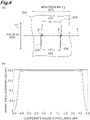
- FIG. 4(a) is a diagram illustrating a shape of an opening part of an aperture mask according to an embodiment.
- This aperture mask 22A similar to the comparative example, has an opening part 24A having a rectangular shape (a quadrangle shape) including opening edges 25A corresponding to a long side and opening edges 25B corresponding to a short side.
- the opening part 24A of the rectangular shape is in a state being rotated around an optical axis of light L0 by a predetermined angle.
- this aperture mask 22A when seen in the direction of the optical axis of the light L0, a state is formed in which the opening edges 25A intersect with a direction parallel to a focusing axis F1 by a predetermined angle, and the opening edges 25B intersect with a direction parallel to a non-focusing axis by a predetermined angle.
- the predetermined angle is equal to or larger than 1° and equal to or smaller than 5°.
- the predetermined angle is equal to or larger than 1°.
- an effect of reduction of interference fringes can be sufficiently exhibited.
- by configuring the predetermined angle to be equal to or smaller than 5° an excessive spread of an edge of the radiation illuminance distribution can be suppressed, and an area in which radiation illuminance is flat can be sufficiently secured.
- a length of the opening part 24A in the direction of the focusing axis F1 may be also considered.
- the aperture mask 22A in a case in which the opening edge 25A is projected onto a focusing line, a projected portion P of the opening edge 25A on the focusing line K has a linear spread. For this reason, in the aperture mask 22A, when the light L0 that has passed through the opening part 24A is focused by a light focusing element 23, interference fringes due to diffraction in the opening edges 25A can be suppressed from overlapping each other on the focusing line K and being strengthened together.
- Fig. 4(b) is a graph representing a radiation illuminance distribution of planar light acquired in a case in which the aperture mask according to the embodiment is used.
- a coordinate value on the focusing line (X axis) is represented in a horizontal axis
- radiation illuminance of planar light is represented in a vertical axis.
- the amplitude of the radiation illuminance distribution near both ends in the X-axis direction is suppressed to be about 1 W/mm 2
- the amplitude of the radiation illuminance distribution near the center is suppressed to be nearly 0 W/mm 2 .
- a corresponding projected portion P has a linear spread.
- interference fringes due to diffraction in the opening edges 25A are strengthened together, and the radiation illuminance distribution of the planar light L1 tends to be non-uniform.
- the planar light L1 having a uniform radiation illuminance distribution can be output.
- an optical filter called an apodizing filter or a soft aperture
- a diffraction component is suppressed by disposing an aspherical lens on an optical path instead of an optical filter.
- an optical element needs to be optimized in accordance with a wavelength or a beam diameter of used laser light, and, in a case in which laser light not matching characteristics of the optical element is used, there is concern that the effect of suppressing interference fringes due to diffraction of light on an opening edge may not be sufficiently exhibited.
- the light irradiation device 2 suppresses interference fringes due to diffraction of light L0 on the opening edges 25A using the configuration of the opening edges 25A of the aperture mask 22A.
- an optical element does not need to be optimized in accordance with a wavelength or a beam diameter of used light L0, and operations/effects are acquired for various kinds of light L0.
- applications to devices assumed to irradiate a sample S with light L0 of different wavelengths or different beam diameters on the same axis as the planar light L1 are particularly meaningful.
- Fig. 5(a) is a diagram illustrating a shape of an opening part of an aperture mask according to another embodiment.
- a shape of an opening part 24B is a parallelogram (a quadrangle shape).
- opening edges 25A when seen in the direction of an optical axis of light L0, opening edges 25A are inclined with respect to a direction parallel to a focusing axis F1 by a predetermined angle, and opening edges 25B are in a state of being parallel to a non-focusing axis.
- Fig. 6(a) is a diagram illustrating a shape of an opening part of an aperture mask according to further another embodiment.
- an opening part 24C has an asymmetrical shape with respect to a focusing line K. More specifically, in the example illustrated in Fig. 6(a) , a shape of the opening part 24C is an isosceles trapezoid (a quadrangle shape).
- opening edges 25A when seen in the direction of an optical axis of light L0, opening edges 25A are inclined with respect to a direction parallel to a focusing axis F1 by a predetermined angle, and opening edges 25B are in the state of being parallel to a non-focusing axis.
- Fig. 7(a) is a diagram illustrating a shape of an opening part of an aperture mask according to further another embodiment.
- the aperture mask 22D illustrated in the drawing similar to the aperture mask 22C, in addition to a shape of an opening part 24D being an isosceles trapezoid, opening edges 25A thereof are in a zigzag shape.
- a projected portion P of the opening edge 25A on the focusing line K has a linear spread.
- a radiation illuminance distribution of planar light L1 formed in a case in which the aperture mask 22D is used is almost the same as that formed in a case in which the aperture mask 22A is used.
- the result illustrated in Fig. 7(b) and the result illustrated in Fig. 4(b) are compared with each other, in the result illustrated in Fig. 7(b) , rising parts of a radiation illuminance distribution near both ends of planar light L1 in the X-axis direction are steep, and amplitudes of the radiation illuminance distribution near both the ends in the X-axis direction are slightly decreased.
- the unevenness of the opening edge 25A having the zigzag shape has a steep shape
- the unevenness of the opening edge 25A may have a curved shape such as an arc shape, a sine wave shape, or the like.
- the opening edges 25A may have a zigzag shape together with rotating an opening part 24E having a rectangular shape (a quadrangle shape) around an optical axis of light L0 by a predetermined angle.
- a radiation illuminance distribution of the planar light L1 that is almost the same as that formed in a case in which the aperture mask 22D is used can be acquired.
- Fig. 9(a) is a diagram illustrating a shape of an opening part of an aperture mask according to further another embodiment.
- opening edges 25A of an opening part 24F have a shape protruding to the outer side of a focusing line K.
- the shape of the opening part 24F is a hexagonal shape, and two sides facing each other are disposed along a direction parallel to a non-focusing axis F2.
- the shape of the opening part 24F is not a regular hexagonal shape, and, in the opening edge 25A, a state is formed in which positions of corners of the hexagon are biased to one side (here, a lower side of the sheet face) of the focusing line K.
- this opening part 24F has an asymmetrical shape with respect to the focusing line K.
- the positions of the corners of the hexagon may be in the state of being biased to the other side (an upper side of the sheet face) of the focusing line K.
- a radiation illuminance distribution of planar light L1 formed in a case in which the aperture mask 22C is used is almost the same as that formed in a case in which the aperture mask 22A is used, and the amplitudes of the radiation illuminance distribution near both ends in the X-axis direction are further suppressed.
- the opening edge 25A has a shape protruding to the outer side of the focusing line K
- a shape in which the opening edge 25A of an opening part 24G having a rectangular shape is gently bent such that it protrudes to the outer side may be used.
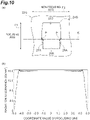
- Fig. 10(b) in a radiation illuminance distribution of the planar light L1, slight amplitudes occur in rising portions of the radiation illuminance distribution at near both ends in the X-axis direction, and almost the same result as that acquired in a case in which the aperture mask 22A is used is acquired as a whole.
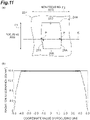
- the opening edge 25A has a shape protruding to the outer side of the focusing line K, for example, like an aperture mask 22H illustrated in Fig. 11(a)
- a shape in which the opening edge 25A is gently bent such that it protrudes to the outer side together with rotating an opening part 24H having a rectangular shape around an optical axis of the light L0 by a predetermined angle may be used.
- Fig. 11(a) a shape in which the opening edge 25A is gently bent such that it protrudes to the outer side together with rotating an opening part 24H having a rectangular shape around an optical axis of the light L0 by a predetermined angle
Landscapes
- Physics & Mathematics (AREA)
- General Physics & Mathematics (AREA)
- Optics & Photonics (AREA)
- Chemical & Material Sciences (AREA)
- Analytical Chemistry (AREA)
- Health & Medical Sciences (AREA)
- Engineering & Computer Science (AREA)
- Multimedia (AREA)
- Life Sciences & Earth Sciences (AREA)
- Biochemistry (AREA)
- General Health & Medical Sciences (AREA)
- Immunology (AREA)
- Pathology (AREA)
- Nuclear Medicine, Radiotherapy & Molecular Imaging (AREA)
- Computer Vision & Pattern Recognition (AREA)
- Microscoopes, Condenser (AREA)
Abstract
Description
- The present disclosure relates to a light irradiation device and a sample observation apparatus.
- As one of methods for observing the inside of a sample having a three-dimensional stereoscopic structure such as a cell or the like, selective plane illumination microscopy (SPIM) is known. As a technology relating to such a technique, for example, there is a sample observation apparatus described in
Patent Literature 1. The sample observation apparatus of thisPatent Literature 1 is configured to include an irradiation optical system that irradiates a sample with planar light, a scanning unit that scans a sample for an irradiation face of planar light, and an imaging optical system that has an observation axis inclined with respect to the irradiation face and forms an image of observation light generated in a sample in accordance with irradiation of planar light. Then, a plurality of pieces of partial image data corresponding to a part of an optical image according to observation light formed as an image by the imaging optical system are acquired, and observation image data of a sample is generated on the basis of such partial image data. - [Patent Literature 1]
Japanese Unexamined Patent Publication No. 2018-063292 - For example, the planar light used in the sample observation apparatus described above is formed by focusing light emitted from a light source using a light focusing element such as a cylindrical lens or the like. In irradiation of planar light onto a sample, it is preferable to limit an irradiation range of the planar light by disposing an aperture mask on an optical path such that observation areas of the sample adjacent to each other are not irradiated with the planar light. However, coherent light, for example, such as laser light is light having coherence, and thus interference fringes due to diffraction on the edge of the aperture mask are generated, and there is concern that a radiation illuminance distribution of the planar light may become non-uniform.
- The present disclosure is for solving the problems described above, and an object thereof is to provide a light irradiation device and a sample observation apparatus capable of outputting planar light having a uniform radiation illuminance distribution.
- According to one aspect of the present disclosure, there is provided a light irradiation device including: a light source configured to output light having coherence; a light focusing element having a focusing axis and a non-focusing axis intersecting with the focusing axis and configured to focus the light on a focusing line so as to generate planar light; and an aperture mask having an opening part that limits a part of luminous fluxes of the light transmitted from the light source to the light focusing element, in which the opening part of the aperture mask has opening edges disposed to extend in a direction along the focusing axis of the light focusing element, and, in a case in which the opening edges are projected onto the focusing line, corresponding projected portions have linear spreads.
- In this light irradiation device, in the opening part of the aperture mask, in a case in which the opening edges disposed to extend in a direction along the focusing axis of the light focusing element are projected onto the focusing line, corresponding projected portions have linear spreads. In an aperture mask in which a corresponding projected portion is punctiform in a case in which the opening edges are projected onto the focusing line, interference fringes due to diffraction in the opening edges are mutually strengthened, and a radiation illuminance distribution of planar light tends to be non-uniform. In contrast to this, in an aperture mask in which the corresponding projected portions have linear spreads, interference fringes due to diffraction in the opening edges are not strengthened together, and the radiation illuminance distribution of the planar light can be uniformized. Thus, this light irradiation device can output planar light having a uniform radiation illuminance distribution.
- The opening part may have an asymmetrical shape with respect to the focusing line. In addition, the opening edges may have shapes protruding to an outer side with respect to the focusing line. The opening part may have a hexagonal shape. According to such a configuration, interference fringes due to diffraction in the opening edges are further suppressed, and the radiation illuminance distribution of the planar light is further uniformized.
- The opening part may have a trapezoid shape. The opening edges may have a zigzag shape. The opening edges may have a shape protruding to an outer side of the focusing line. Also in such a configuration, interference fringes due to diffraction in the opening edges are further suppressed, and the radiation illuminance distribution of the planar light is further uniformized.
- The opening part may have a quadrangle shape, and the opening edges may intersect with the focusing axis at a predetermined angle. Also in such a configuration, interference fringes due to diffraction in the opening edges are further suppressed, and the radiation illuminance distribution of the planar light is further uniformized.
- The light source may be a light source that outputs laser light as the light. The laser light is light, from which high radiation illuminance can be acquired, but has high coherence, and interference fringes due to diffraction in edges of an aperture mask may be easily generated. Thus, by applying an aperture mask having the configuration described above to laser light, planar light having a uniform radiation illuminance distribution can be appropriately output.
- According to one aspect of the present disclosure, there is provided a sample observation apparatus including: the light irradiation device described above; and a detection unit configured to detect observation light generated in a sample in accordance with irradiation of the planar light from the light irradiation device.
- In this sample observation apparatus, interference fringes due to diffraction in the opening edges of the aperture mask are not strengthened together, and the radiation illuminance distribution of the planar light can be uniformized. Thus, in this sample observation apparatus, by irradiating a sample with planar light of which the radiation illuminance distribution is uniformized, observation of the sample can be performed with high accuracy.
- According to the present disclosure, planar light having a uniform radiation illuminance distribution can be output.
-
-
Fig. 1 is a schematic configuration diagram illustrating a sample observation apparatus according to an embodiment. -
Fig. 2 is a schematic diagram illustrating an example of a configuration of a light irradiation device. -
Fig. 3(a) is a diagram illustrating a shape of an opening part of an aperture mask according to a comparative example, andFig. 3(b) is a graph representing a radiation illuminance distribution of planar light acquired in a case in which this aperture mask is used. -
Fig. 4(a) is a diagram illustrating a shape of an opening part of an aperture mask according to an embodiment, andFig. 4(b) is a graph representing a radiation illuminance distribution of planar light acquired in a case in which this aperture mask is used. -
Fig. 5(a) is a diagram illustrating a shape of an opening part of an aperture mask according to another embodiment, andFig. 5(b) is a graph representing a radiation illuminance distribution of planar light acquired in a case in which this aperture mask is used. -
Fig. 6(a) is a diagram illustrating a shape of an opening part of an aperture mask according to still another embodiment, andFig. 6(b) is a graph representing a radiation illuminance distribution of planar light acquired in a case in which this aperture mask is used. -
Fig. 7(a) is a diagram illustrating a shape of an opening part of an aperture mask according to further another embodiment, andFig. 7(b) is a graph representing a radiation illuminance distribution of planar light acquired in a case in which this aperture mask is used. -
Fig. 8(a) is a diagram illustrating a shape of an opening part of an aperture mask according to further another embodiment, andFig. 8(b) is a graph representing a radiation illuminance distribution of planar light acquired in a case in which this aperture mask is used. -
Fig. 9(a) is a diagram illustrating a shape of an opening part of an aperture mask according to further another embodiment, andFig. 9(b) is a graph representing a radiation illuminance distribution of planar light acquired in a case in which this aperture mask is used. -
Fig. 10(a) is a diagram illustrating a shape of an opening part of an aperture mask according to further another embodiment, andFig. 10(b) is a graph representing a radiation illuminance distribution of planar light acquired in a case in which this aperture mask is used. -
Fig. 11(a) is a diagram illustrating a shape of an opening part of an aperture mask according to further another embodiment, andFig. 11(b) is a graph representing a radiation illuminance distribution of planar light acquired in a case in which this aperture mask is used. - Hereinafter, preferred embodiments of a light irradiation device and a sample observation apparatus according to one aspect of the present disclosure will be described in detail with reference to the drawings.
-
Fig. 1 is a schematic configuration diagram illustrating a sample observation apparatus according to an embodiment. Thissample observation apparatus 1 is an apparatus that acquires observation image data of the inside of a sample S by irradiating the sample S with planar light L1 and forming an image of light (for example, fluorescence, scattering light, or the like) generated inside the sample S in accordance with the irradiation of the planar light L1 on an imaging surface. As asample observation apparatus 1 of such a type, there is a slide scanner that acquires and displays an image of a sample S stored in a slide glass, a plate reader that acquires image data of a sample S stored on a micro plate and analyzes the image data, or the like. For example, as the sample S that is an observation target, there is a cell, a tissue, or an organ of a person or an animal, an animal or a plant, a cell, an organ, or the like of a plant, or the like. The sample S may be contained in a solution, a gel, or a material of which a refractive index is different from that of the sample S. - As illustrated in
Fig. 1 , thesample observation apparatus 1 is configured to include alight irradiation device 2, ascanning unit 4, an imaging optical system 5, an image acquiring unit (a detection unit) 6, and acomputer 7. Thelight irradiation device 2 is a device that outputs planar light L1 to irradiate a sample S. The planar light L1 is light that can be acquired by shaping laser light or low coherent light into a planar shape. The planar light L1 output from thelight irradiation device 2 advances along an optical axis PI, and a sample S is irradiated therewith. In the sample S that has been irradiated with the planar light L1, observation light L2 is generated on an irradiation surface R of the planar light L1. For example, the observation light L2 is fluorescence excited by the planar light L1, scattering light of the planar light L1, or a diffused reflected light of the planar light L1. - The
scanning unit 4 is a mechanism that scans a sample S for the irradiation surface R of the planar light L1. In this embodiment, thescanning unit 4 is configured using a movingstage 12 that moves asample container 11 storing a sample S. For example, thesample container 11 is a micro plate, a slide glass, a Petri dish, or the like. In this embodiment, a micro plate will be illustrated as an example. In thesample container 11, a plurality ofwells 13 in which samples S are disposed are aligned, for example, in a linear shape (or a matrix shape). Thesample container 11 may be fixed with respect to the movingstage 12. A bottom face of the well 13 serves as an input face of planar light L1 for a sample S disposed inside thewell 13. Thesample container 11 is disposed with respect to the movingstage 12 such that this input face is orthogonal to the optical axis P1 of the planar light L1. - As illustrated in
Fig. 1 , this movingstage 12 scans thesample container 11 in a direction set in advance in accordance with a control signal from thecomputer 7. In this embodiment, the movingstage 12 scans thesample container 11 in one direction within a plane orthogonal to the optical axis P1 of the planar light L1. Here, a direction of the optical axis P1 of the planar light L1 will be referred to as a Z axis, a scanning direction of thesample container 11 according to the movingstage 12 will be referred to as a Y axis, and a direction orthogonal to the Y axis within a plane that is orthogonal to the optical axis P1 of the planar light L1 will be referred to as an X axis. An irradiation surface R of the planar light L1 with respect to the sample S is a face within an XZ plane. - The imaging optical system 5 is an optical system that forms an image of the observation light L2 generated in the sample S in accordance with the irradiation of the planar light L1. For example, the imaging optical system 5 is configured to include an objective lens, an imaging lens, and the like. An optical axis of the imaging optical system 5 is an observation axis P2 of the observation light L2. In the example illustrated in
Fig. 1 , the observation axis P2 of the imaging optical system 5 is inclined with respect to the irradiation surface R of the planar light L1 in the sample S by a predetermined angle. An inclination angle of the observation axis P2 is in the state of coinciding with an angle formed by the optical axis P1 of the planar light L1 facing the sample S and the observation axis P2. - The
image acquiring unit 6 is a part that detects observation light L2 formed as an image by the imaging optical system 5. For example, theimage acquiring unit 6 is configured to include an imaging device that captures an optical image according to the observation light L2. Examples of the imaging device includes area image sensors such as a CMOS image sensor and a CCD image sensor. Such an area image sensor is disposed in the imaging surface according to the imaging optical system 5 and, for example, captures an optical image using a global shutter or a rolling shutter and outputs data of a two-dimensional image to thecomputer 7. - The
computer 7, physically, is configured to include memories such as a RAM, a ROM, and the like, a processor (an arithmetic operation circuit) such as a CPU or the like, a communication interface, a storage unit such as a hard disk or the like, and a display unit such as a display or the like. Examples of thecomputer 7 include a personal computer, a cloud server, a smart device (a smartphone, a tablet terminal, or the like), and the like. Thecomputer 7 executes a program stored in a memory using a CPU of the computer system, thereby functioning as a controller that controls operations of thelight irradiation device 2 and the movingstage 12, an image generating unit that generates observation image data of a sample S, an analysis unit that analyzes the observation image data, and the like. - Next, the
light irradiation device 2 described above will be described in more details. -
Fig. 2 is a schematic diagram illustrating an example of a configuration of the light irradiation device. As illustrated in the drawing, although details will be described below, thelight irradiation device 2 is configured to include alight source 21 that outputs light L0, anaperture mask 22 that limits a part of luminous fluxes of the light L0, and alight focusing element 23 that generates planar light L1 by focusing the light L0. Examples of thelight source 21 include laser light sources such as a laser diode and a solid-state laser light source. Thelight source 21 is not limited to a light source that outputs laser light and, for example, may be a light source that outputs low coherent light such as a super luminescent diode (SLD). Both the laser light and the low coherent light are light having coherence. Theaperture mask 22A has anopening part 24 that limits a part of luminous fluxes of the light L0 transmitted from thelight source 21 toward thelight focusing element 23. By limiting a part of the luminous fluxes of the light L0 using theopening part 24, an irradiation range of the planar light L1 output from thelight irradiation device 2 can be limited such that observation areas adjacent to each other with respect to a sample S disposed in thesample container 11 of thesample observation apparatus 1 are not irradiated with the planar light. - The
light focusing element 23, for example, is configured using a cylindrical lens, an axicon lens, a freeform lens, a spatial light modulator, or the like and is optically coupled with thelight source 21. Thislight focusing element 23 has a focusing axis F1 and a non-focusing axis F2 that intersects with (here, orthogonal to) the focusing axis F1 and generates planar light L1 by focusing the light L0 that has passed through the openingpart 24 on a focusing line K. In the example illustrated inFig. 2 , thelight focusing element 23 is a cylindrical lens.Fig. 2(a) illustrates an optical axis of the light L0 on a focusing axis-side cross-section (a YZ cross-section) of thelight focusing element 23, andFig. 2(b) illustrates an optical axis of the light L0 on a non-focusing axis-side cross-section (an XZ cross-section) of thelight focusing element 23. - As illustrated in
Fig. 2(a) , when seen from the focusing axis-side cross-section (the YZ cross-section), the light L0 that has passed through the openingpart 24 passes through thelight focusing element 23, thereby being focused along the focusing axis F1 of thelight focusing element 23. On the other hand, as illustrated inFig. 2(b) , when seen from the non-focusing axis-side cross-section (the XZ cross-section), the light L0 that has passed through the openingpart 24 maintains a state that is a state before incidence to thelight focusing element 23 without being focused by thelight focusing element 23. Thus, by passing through thelight focusing element 23, the light L0 is focused in only one axis (the Y axis) of the focusing axis F1 to become planar light L1 having a constant width in the X-axis direction. - Here, as described above, in a case in which an aperture mask is disposed on an optical path of coherent light such as laser light, generally, coherent light is light having strong coherence, and thus there is a problem in that interference fringes are generated in laser light after passage of an opening part due to diffraction in an opening edge of the aperture mask. This problem can similarly occur even in a case in which light passing through an opening part of the aperture mask is low coherent light. The interference fringes due to diffraction in the opening edge of the aperture mask overlap each other and are strengthened together when light is focused in a direction along a focusing axis by a light focusing element, and thus, it may be considered that a radiation illuminance distribution of planar light acquired by focusing light becomes non-uniform.
-
Fig. 3(a) is a diagram illustrating a shape of an opening part of an aperture mask according to a comparative example. Theaperture mask 122 according to this comparative example has anopening part 124 having a rectangular shape (a quadrangle shape) including openingedges 125A corresponding to a long side and openingedges 125B corresponding to a short side. Theaperture mask 122 is disposed on an optical path of light L0 such that the openingedges 125A extend in a direction parallel to a focusing axis F1 of alight focusing element 23, and the opening edges 125B extend in a direction orthogonal to the focusing axis of thelight focusing element 23 when seen in a direction of the optical axis of the light L0. A focusing line K of the light L0 according to thelight focusing element 23 is positioned at a line joining centers of the left and right opening edges 125A and 125A when seen in the direction of the optical axis of the light L0. - In the
aperture mask 122 according to this comparative example, as illustrated inFig. 3(a) , in a case in which theopening edge 125A is projected onto a focusing line, a projected portion P on the focusing line K of the openingedge 125A is formed to have a punctiform. For this reason, in theaperture mask 122, when the light L0 that has passed through theopening part 124 is focused by thelight focusing element 23, interference fringes due to diffraction in theopening edge 125A are superimposed as one point on the focusing line K and are strengthened together. -
Fig. 3(b) is a graph representing a radiation illuminance distribution of planar light acquired in a case in which the aperture mask according to a comparative example is used. In the drawing, a coordinate value on the focusing line (X axis) is represented in a horizontal axis, and radiation illuminance of planar light is represented in a vertical axis. As illustrated in the drawing, in the planar light L1 acquired in a case in which the aperture mask according to the comparative example is used, the amplitude of the radiation illuminance distribution near both ends in the X-axis direction becomes large to be equal to or larger than 5 W/mm2. While the amplitude of the radiation illuminance distribution decreases toward the center in the X axis direction, the amplitude of the radiation illuminance distribution near the center is about 1 W/mm2. The amplitude of the radiation illuminance distribution represents a width between a maximum value and a minimum value in an area in which radiation illuminance is approximately uniform. - On the other hand,
Fig. 4(a) is a diagram illustrating a shape of an opening part of an aperture mask according to an embodiment. Thisaperture mask 22A, similar to the comparative example, has anopening part 24A having a rectangular shape (a quadrangle shape) including openingedges 25A corresponding to a long side and openingedges 25B corresponding to a short side. In theaperture mask 22A, although the shape of theopening part 24A is the same as that of theopening part 124 of the comparative example, differently from the comparative example, theopening part 24A of the rectangular shape is in a state being rotated around an optical axis of light L0 by a predetermined angle. In accordance with this, in thisaperture mask 22A, when seen in the direction of the optical axis of the light L0, a state is formed in which the opening edges 25A intersect with a direction parallel to a focusing axis F1 by a predetermined angle, and the opening edges 25B intersect with a direction parallel to a non-focusing axis by a predetermined angle. - For example, the predetermined angle is equal to or larger than 1° and equal to or smaller than 5°. By configuring the predetermined angle to be equal to or larger than 1°, an effect of reduction of interference fringes can be sufficiently exhibited. In addition, by configuring the predetermined angle to be equal to or smaller than 5°, an excessive spread of an edge of the radiation illuminance distribution can be suppressed, and an area in which radiation illuminance is flat can be sufficiently secured. Relating to setting of an optimal predetermined angle, a length of the
opening part 24A in the direction of the focusing axis F1 may be also considered. - In the
aperture mask 22A according to this embodiment, as illustrated inFig. 4(a) , in a case in which theopening edge 25A is projected onto a focusing line, a projected portion P of the openingedge 25A on the focusing line K has a linear spread. For this reason, in theaperture mask 22A, when the light L0 that has passed through theopening part 24A is focused by alight focusing element 23, interference fringes due to diffraction in the opening edges 25A can be suppressed from overlapping each other on the focusing line K and being strengthened together. -
Fig. 4(b) is a graph representing a radiation illuminance distribution of planar light acquired in a case in which the aperture mask according to the embodiment is used. In the drawing, similar toFig. 3(b) , a coordinate value on the focusing line (X axis) is represented in a horizontal axis, and radiation illuminance of planar light is represented in a vertical axis. As illustrated in the drawing, in the planar light L1 acquired in a case in which the aperture mask according to the embodiment is used, the amplitude of the radiation illuminance distribution near both ends in the X-axis direction is suppressed to be about 1 W/mm2, and the amplitude of the radiation illuminance distribution near the center is suppressed to be nearly 0 W/mm2. - As described above, in the
light irradiation device 2, in a case in which the opening edges 25A that are disposed to extend in a direction along the focusing axis F1 of thelight focusing element 23 are projected onto the focusing line K in theopening part 24A of theaperture mask 22A, a corresponding projected portion P has a linear spread. In theaperture mask 22 of the comparative example in which a corresponding projected portion P is in a punctiform in a case in which the opening edges 25A are projected onto the focusing line K, interference fringes due to diffraction in the opening edges 25A are strengthened together, and the radiation illuminance distribution of the planar light L1 tends to be non-uniform. In contrast to this, in theaperture mask 22A according to the embodiment in which the corresponding projected portion P has a linear spread, interference fringes due to diffraction in the opening edges 25A are not strengthened together, and the radiation illuminance distribution of the planar light L1 can be uniformized. Thus, in thislight irradiation device 2, the planar light L1 having a uniform radiation illuminance distribution can be output. - As a technology for suppressing interference fringes due to diffraction of light on the opening edge of an aperture mask, for example, there is a technique in which an optical filter called an apodizing filter or a soft aperture is disposed on an optical path. In addition, there is also a technique in which a diffraction component is suppressed by disposing an aspherical lens on an optical path instead of an optical filter. However, in such techniques, an optical element needs to be optimized in accordance with a wavelength or a beam diameter of used laser light, and, in a case in which laser light not matching characteristics of the optical element is used, there is concern that the effect of suppressing interference fringes due to diffraction of light on an opening edge may not be sufficiently exhibited.
- In contrast to this, the
light irradiation device 2 suppresses interference fringes due to diffraction of light L0 on the opening edges 25A using the configuration of the opening edges 25A of theaperture mask 22A. In this technique, an optical element does not need to be optimized in accordance with a wavelength or a beam diameter of used light L0, and operations/effects are acquired for various kinds of light L0. As in thesample observation apparatus 1 represented in the embodiment described above, applications to devices assumed to irradiate a sample S with light L0 of different wavelengths or different beam diameters on the same axis as the planar light L1 are particularly meaningful. -
Fig. 5(a) is a diagram illustrating a shape of an opening part of an aperture mask according to another embodiment. In theaperture mask 22B illustrated in the drawing, instead of the configuration (seeFig. 4(a) ) in which theopening part 24A having a rectangular shape is rotated around the optical axis of the light L0 by a predetermined angle, a shape of anopening part 24B is a parallelogram (a quadrangle shape). In accordance with this, in thisaperture mask 22B, when seen in the direction of an optical axis of light L0, openingedges 25A are inclined with respect to a direction parallel to a focusing axis F1 by a predetermined angle, and openingedges 25B are in a state of being parallel to a non-focusing axis. - Also in such an
aperture mask 22B, as illustrated inFig. 5(a) , in a case in which theopening edge 25A is projected onto a focusing line, a projected portion P of the openingedge 25A on the focusing line K has a linear spread. For this reason, also in theaperture mask 22B, when light L0 that has passed through theopening part 24B is focused by alight focusing element 23, interference fringes due to diffraction in theopening edge 25A can be suppressed from overlapping each other on the focusing line K and being strengthened together. As illustrated inFig. 5(b) , a radiation illuminance distribution of the planar light L1 formed in a case in which theaperture mask 22B is used is almost the same as that formed in a case in which theaperture mask 22A is used. -
Fig. 6(a) is a diagram illustrating a shape of an opening part of an aperture mask according to further another embodiment. In theaperture mask 22C illustrated in the drawing, anopening part 24C has an asymmetrical shape with respect to a focusing line K. More specifically, in the example illustrated inFig. 6(a) , a shape of theopening part 24C is an isosceles trapezoid (a quadrangle shape). In accordance with this, in thisaperture mask 22C, when seen in the direction of an optical axis of light L0, openingedges 25A are inclined with respect to a direction parallel to a focusing axis F1 by a predetermined angle, and openingedges 25B are in the state of being parallel to a non-focusing axis. In the drawing, although a length of a lower base of theopening part 24C in the direction of the non-focusing axis F2 is longer than a length of an upper base in the direction of the non-focusing axis F2, this relation in the lengths may be reversed. - Also in such an
aperture mask 22C, as illustrated inFig. 6(a) , in a case in which theopening edge 25A is projected onto a focusing line, a projected portion P of the openingedge 25A on the focusing line K has a linear spread. For this reason, also in theaperture mask 22C, when light L0 that has passed through theopening part 24C is focused by alight focusing element 23, interference fringes due to diffraction in theopening edge 25A can be suppressed from overlapping each other on the focusing line K and being strengthened together. As illustrated inFig. 6(b) , a radiation illuminance distribution of the planar light L1 formed in a case in which theaperture mask 22C is used is almost the same as that formed in a case in which theaperture mask 22A is used. -
Fig. 7(a) is a diagram illustrating a shape of an opening part of an aperture mask according to further another embodiment. In theaperture mask 22D illustrated in the drawing, similar to theaperture mask 22C, in addition to a shape of anopening part 24D being an isosceles trapezoid, openingedges 25A thereof are in a zigzag shape. Also in such anaperture mask 22D, in a case in which theopening edge 25A is projected onto a focusing line, a projected portion P of the openingedge 25A on the focusing line K has a linear spread. For this reason, also in theaperture mask 22D, when light L0 that has passed through theopening part 24D is focused by alight focusing element 23, interference fringes due to diffraction in theopening edge 25A can be suppressed from overlapping each other on the focusing line K and being strengthened together. - As illustrated in
Fig. 7(b) , a radiation illuminance distribution of planar light L1 formed in a case in which theaperture mask 22D is used is almost the same as that formed in a case in which theaperture mask 22A is used. When the result illustrated inFig. 7(b) and the result illustrated inFig. 4(b) are compared with each other, in the result illustrated inFig. 7(b) , rising parts of a radiation illuminance distribution near both ends of planar light L1 in the X-axis direction are steep, and amplitudes of the radiation illuminance distribution near both the ends in the X-axis direction are slightly decreased. In the example illustrated inFig. 7(a) , although the unevenness of the openingedge 25A having the zigzag shape has a steep shape, the unevenness of the openingedge 25A may have a curved shape such as an arc shape, a sine wave shape, or the like. - In addition, as in an
aperture mask 22E illustrated inFig. 8(a) , the opening edges 25A may have a zigzag shape together with rotating anopening part 24E having a rectangular shape (a quadrangle shape) around an optical axis of light L0 by a predetermined angle. Also in a case in which such anaperture mask 22E is used, as illustrated inFig. 8(b) , a radiation illuminance distribution of the planar light L1 that is almost the same as that formed in a case in which theaperture mask 22D is used can be acquired. -
Fig. 9(a) is a diagram illustrating a shape of an opening part of an aperture mask according to further another embodiment. In theaperture mask 22F illustrated in the drawing, openingedges 25A of anopening part 24F have a shape protruding to the outer side of a focusing line K. More specifically, in the example illustrated inFig. 9(a) , the shape of theopening part 24F is a hexagonal shape, and two sides facing each other are disposed along a direction parallel to a non-focusing axis F2. The shape of theopening part 24F is not a regular hexagonal shape, and, in theopening edge 25A, a state is formed in which positions of corners of the hexagon are biased to one side (here, a lower side of the sheet face) of the focusing line K. Thus, similar to theopening part 24C of theaperture mask 22C, thisopening part 24F has an asymmetrical shape with respect to the focusing line K. The positions of the corners of the hexagon may be in the state of being biased to the other side (an upper side of the sheet face) of the focusing line K. - Also in such an
aperture mask 22F, in a case in which theopening edge 25A is projected onto a focusing line, a projected portion P of the openingedge 25A on the focusing line K has a linear spread. For this reason, also in theaperture mask 22F, when light L0 that has passed through theopening part 24F is focused by alight focusing element 23, interference fringes due to diffraction in theopening edge 25A can be suppressed from overlapping each other on the focusing line K and being strengthened together. As illustrated inFig. 9(b) , a radiation illuminance distribution of planar light L1 formed in a case in which theaperture mask 22C is used is almost the same as that formed in a case in which theaperture mask 22A is used, and the amplitudes of the radiation illuminance distribution near both ends in the X-axis direction are further suppressed. - As a form in which the
opening edge 25A has a shape protruding to the outer side of the focusing line K, for example, like anaperture mask 22G illustrated inFig. 10(a) , a shape in which theopening edge 25A of anopening part 24G having a rectangular shape is gently bent such that it protrudes to the outer side may be used. In this case, as illustrated inFig. 10(b) , in a radiation illuminance distribution of the planar light L1, slight amplitudes occur in rising portions of the radiation illuminance distribution at near both ends in the X-axis direction, and almost the same result as that acquired in a case in which theaperture mask 22A is used is acquired as a whole. - In addition, as another form in which the
opening edge 25A has a shape protruding to the outer side of the focusing line K, for example, like anaperture mask 22H illustrated inFig. 11(a) , a shape in which theopening edge 25A is gently bent such that it protrudes to the outer side together with rotating anopening part 24H having a rectangular shape around an optical axis of the light L0 by a predetermined angle may be used. In this case, as illustrated inFig. 11(b) , in a radiation illuminance distribution of the planar light L1, slight amplitudes occur in rising portions of the radiation illuminance distribution at near both ends in the X-axis direction, and almost the same result as that acquired in a case in which theaperture mask 22A is used is acquired as a whole. -
- 1 sample observation apparatus
- 6 image acquiring unit (detection unit)
- 21 light source
- 22 (22A to 22H) aperture mask
- 23 light focusing element
- 24 (24A to 24H) opening part
- 25A opening edge
- F1 focusing axis
- F2 non-focusing axis
- K focusing line
- L0 light
- L1 planar light
- P projected portion
- S sample
Claims (9)
- A light irradiation device comprising:a light source configured to output light having coherence;a light focusing element having a focusing axis and a non-focusing axis intersecting with the focusing axis and configured to focus the light on a focusing line so as to generate planar light; andan aperture mask having an opening part that limits a part of luminous fluxes of the light transmitted from the light source to the light focusing element,wherein the opening part of the aperture mask has opening edges disposed to extend in a direction along the focusing axis of the light focusing element, and, in a case in which the opening edges are projected onto the focusing line, corresponding projected portions have linear spreads.
- The light irradiation device according to claim 1, wherein the opening part has an asymmetrical shape with respect to the focusing line.
- The light irradiation device according to claim 1 or 2, wherein the opening edges have shapes protruding to an outer side of the focusing line.
- The light irradiation device according to any one of claims 1 to 3, wherein the opening part has a hexagonal shape.
- The light irradiation device according to claim 1 or 2, wherein the opening part has a trapezoid shape.
- The light irradiation device according to any one of claims 1 to 5, wherein the opening edges have a zigzag shape.
- The light irradiation device according to claim 1,wherein the opening part has a quadrangle shape, andwherein the opening edges intersect with the focusing axis at a predetermined angle.
- The light irradiation device according to any one of claims 1 to 7, wherein the light source is a light source that outputs laser light as the light.
- A sample observation apparatus comprising:the light irradiation device according to any one of claims 1 to 8; anda detection unit configured to detect observation light generated in a sample in accordance with irradiation of the planar light from the light irradiation device.
Applications Claiming Priority (2)
| Application Number | Priority Date | Filing Date | Title |
|---|---|---|---|
| JP2020092274 | 2020-05-27 | ||
| PCT/JP2021/010878 WO2021240960A1 (en) | 2020-05-27 | 2021-03-17 | Light irradiation device and sample observation apparatus |
Publications (3)
| Publication Number | Publication Date |
|---|---|
| EP4105704A1 true EP4105704A1 (en) | 2022-12-21 |
| EP4105704A4 EP4105704A4 (en) | 2024-03-20 |
| EP4105704B1 EP4105704B1 (en) | 2026-04-22 |
Family
ID=78723313
Family Applications (1)
| Application Number | Title | Priority Date | Filing Date |
|---|---|---|---|
| EP21814612.4A Active EP4105704B1 (en) | 2020-05-27 | 2021-03-17 | Light irradiation device and sample observation apparatus |
Country Status (5)
| Country | Link |
|---|---|
| US (2) | US12140742B2 (en) |
| EP (1) | EP4105704B1 (en) |
| JP (1) | JP7662631B2 (en) |
| CN (1) | CN115668027B (en) |
| WO (1) | WO2021240960A1 (en) |
Family Cites Families (11)
| Publication number | Priority date | Publication date | Assignee | Title |
|---|---|---|---|---|
| US5148315A (en) * | 1987-01-28 | 1992-09-15 | Vladimir F. Tamari | Method and means to cancel diffraction effects from radiation fields |
| JP2685252B2 (en) * | 1988-06-15 | 1997-12-03 | 株式会社リコー | Aperture stop for semiconductor laser optical system |
| JP3319790B2 (en) * | 1992-11-30 | 2002-09-03 | 株式会社日立製作所 | Foreign matter inspection method and apparatus |
| US5479011A (en) * | 1992-12-18 | 1995-12-26 | Spectra-Physics Scanning Systems, Inc. | Variable focus optical system for data reading |
| US5473426A (en) * | 1993-03-05 | 1995-12-05 | Nikon Corporation | Defect inspection apparatus |
| DE19830553A1 (en) * | 1998-07-08 | 2000-01-13 | Sick Ag | Barcode reader |
| JP4344224B2 (en) | 2003-11-21 | 2009-10-14 | 浜松ホトニクス株式会社 | Optical mask and MOPA laser device |
| JP5577885B2 (en) * | 2010-06-28 | 2014-08-27 | ソニー株式会社 | Microscope and focusing method |
| US10310246B2 (en) * | 2016-09-28 | 2019-06-04 | SCREEN Holdings Co., Ltd. | Converter, illuminator, and light sheet fluorescence microscope |
| JP6423841B2 (en) * | 2016-10-11 | 2018-11-14 | 浜松ホトニクス株式会社 | Sample observation apparatus and sample observation method |
| JP7113645B2 (en) | 2018-04-03 | 2022-08-05 | 浜松ホトニクス株式会社 | Sample holder and light sheet microscope |
-
2021
- 2021-03-17 WO PCT/JP2021/010878 patent/WO2021240960A1/en not_active Ceased
- 2021-03-17 EP EP21814612.4A patent/EP4105704B1/en active Active
- 2021-03-17 JP JP2022527532A patent/JP7662631B2/en active Active
- 2021-03-17 CN CN202180037629.1A patent/CN115668027B/en active Active
- 2021-03-17 US US17/924,160 patent/US12140742B2/en active Active
-
2024
- 2024-10-10 US US18/911,797 patent/US20250035901A1/en active Pending
Also Published As
| Publication number | Publication date |
|---|---|
| JPWO2021240960A1 (en) | 2021-12-02 |
| EP4105704A4 (en) | 2024-03-20 |
| US12140742B2 (en) | 2024-11-12 |
| US20230176352A1 (en) | 2023-06-08 |
| WO2021240960A1 (en) | 2021-12-02 |
| US20250035901A1 (en) | 2025-01-30 |
| CN115668027B (en) | 2026-04-21 |
| CN115668027A (en) | 2023-01-31 |
| JP7662631B2 (en) | 2025-04-15 |
| EP4105704B1 (en) | 2026-04-22 |
Similar Documents
| Publication | Publication Date | Title |
|---|---|---|
| EP3239652B1 (en) | Three dimensional camera and projector for same | |
| US20180255289A1 (en) | 3d imaging, ranging, and/or tracking using active illumination and point spread function engineering | |
| US9766442B2 (en) | Confocal scanner and confocal microscope | |
| JP2020502558A (en) | High-speed, high-resolution imaging method for large samples | |
| WO2014117079A1 (en) | Depth of field 3d imaging slm microscope | |
| TW202104856A (en) | High-brightness illumination source for optical metrology | |
| JP7058271B2 (en) | Sample observation device and sample observation method | |
| JP6320436B2 (en) | Imaging apparatus and imaging method | |
| EP3654018A1 (en) | Sample observation device and sample observation method | |
| JP6577793B2 (en) | Light regulating device and imaging method | |
| JP2018063292A (en) | Sample observation apparatus and sample observation method | |
| CN110554508B (en) | Light beam shaping device and light beam shaping method thereof | |
| CN114616484A (en) | Light source, sensor and method of illuminating a scene | |
| EP3779555B1 (en) | Sample observation device | |
| CN104459999A (en) | Illuminating system of imaging flow cytometry | |
| CN104953465A (en) | Homogenizing device for laser diode array light beam based on space spectrum division processing | |
| US20180267283A1 (en) | Image acquisition device and image acquisition method | |
| US12140742B2 (en) | Light irradiation device and sample observation apparatus | |
| JP5197712B2 (en) | Imaging device | |
| US11598952B2 (en) | Optical device, phase plate, and image forming method | |
| JP7007227B2 (en) | Sample observation device and sample observation method | |
| CN107941777B (en) | A bleach-resistant single-molecule localization 3D super-resolution microscopy system | |
| JP2016125894A (en) | Object detection device | |
| CN113302514B (en) | Illumination for zoned time-of-flight imaging | |
| JP7329113B2 (en) | Sample observation device |
Legal Events
| Date | Code | Title | Description |
|---|---|---|---|
| STAA | Information on the status of an ep patent application or granted ep patent |
Free format text: STATUS: THE INTERNATIONAL PUBLICATION HAS BEEN MADE |
|
| PUAI | Public reference made under article 153(3) epc to a published international application that has entered the european phase |
Free format text: ORIGINAL CODE: 0009012 |
|
| STAA | Information on the status of an ep patent application or granted ep patent |
Free format text: STATUS: REQUEST FOR EXAMINATION WAS MADE |
|
| 17P | Request for examination filed |
Effective date: 20220912 |
|
| AK | Designated contracting states |
Kind code of ref document: A1 Designated state(s): AL AT BE BG CH CY CZ DE DK EE ES FI FR GB GR HR HU IE IS IT LI LT LU LV MC MK MT NL NO PL PT RO RS SE SI SK SM TR |
|
| DAV | Request for validation of the european patent (deleted) | ||
| DAX | Request for extension of the european patent (deleted) | ||
| A4 | Supplementary search report drawn up and despatched |
Effective date: 20240216 |
|
| RIC1 | Information provided on ipc code assigned before grant |
Ipc: G02B 27/09 20060101ALI20240212BHEP Ipc: G02B 21/36 20060101ALI20240212BHEP Ipc: G02B 21/00 20060101ALI20240212BHEP Ipc: G02B 21/06 20060101AFI20240212BHEP |
|
| GRAP | Despatch of communication of intention to grant a patent |
Free format text: ORIGINAL CODE: EPIDOSNIGR1 |
|
| STAA | Information on the status of an ep patent application or granted ep patent |
Free format text: STATUS: GRANT OF PATENT IS INTENDED |
|
| RIC1 | Information provided on ipc code assigned before grant |
Ipc: G02B 21/06 20060101AFI20260107BHEP Ipc: G02B 21/36 20060101ALI20260107BHEP Ipc: G02B 27/09 20060101ALI20260107BHEP |
|
| INTG | Intention to grant announced |
Effective date: 20260116 |
|
| GRAS | Grant fee paid |
Free format text: ORIGINAL CODE: EPIDOSNIGR3 |
|
| GRAA | (expected) grant |
Free format text: ORIGINAL CODE: 0009210 |
|
| STAA | Information on the status of an ep patent application or granted ep patent |
Free format text: STATUS: THE PATENT HAS BEEN GRANTED |
|
| AK | Designated contracting states |
Kind code of ref document: B1 Designated state(s): AL AT BE BG CH CY CZ DE DK EE ES FI FR GB GR HR HU IE IS IT LI LT LU LV MC MK MT NL NO PL PT RO RS SE SI SK SM TR |
|
| REG | Reference to a national code |
Ref country code: CH Ref legal event code: F10 Free format text: ST27 STATUS EVENT CODE: U-0-0-F10-F00 (AS PROVIDED BY THE NATIONAL OFFICE) Effective date: 20260422 Ref country code: GB Ref legal event code: FG4D |
|
| REG | Reference to a national code |
Ref country code: CH Ref legal event code: R17 Free format text: ST27 STATUS EVENT CODE: U-0-0-R10-R17 (AS PROVIDED BY THE NATIONAL OFFICE) Effective date: 20260424 |